Height adjustable desk or table
Verhappen February 2, 2
U.S. patent number 10,905,232 [Application Number 16/578,918] was granted by the patent office on 2021-02-02 for height adjustable desk or table. This patent grant is currently assigned to KONINKLIJKE AHREND B.V.. The grantee listed for this patent is Koninklijke Ahrend B.V.. Invention is credited to Henricus Reinier Martina Verhappen.


| United States Patent | 10,905,232 |
| Verhappen | February 2, 2021 |
Height adjustable desk or table
Abstract
A height adjustable desk or table comprising a desk or table top, and a frame with spaced apart legs for supporting the desk or table top, wherein each of the legs comprises a movable upper portion and a lower stationary portion, and wherein a first cable is guided via first guide means connected with a lower end of the movable upper portion of the first leg via second guide means to a lower end of the lower stationary portion of the second leg, and a second cable is guided via third guide means connected with a lower end of the movable upper portion of the second leg via fourth guide means to a lower end of the lower stationary portion of the first leg, wherein each of the legs comprises a gas spring, and wherein for each gas spring the upper portion of the gas spring is arranged to be up-and-down movable portion of the leg and the lower portion of each gas spring is arranged to be the lower stationary portion of the leg.
| Inventors: | Verhappen; Henricus Reinier Martina (Amsterdam, NL) | ||||||||||
|---|---|---|---|---|---|---|---|---|---|---|---|
| Applicant: |
|
||||||||||
| Assignee: | KONINKLIJKE AHREND B.V.
(Amsterdam, NL) |
||||||||||
| Family ID: | 1000005333278 | ||||||||||
| Appl. No.: | 16/578,918 | ||||||||||
| Filed: | September 23, 2019 |
Prior Publication Data
| Document Identifier | Publication Date | |
|---|---|---|
| US 20200093259 A1 | Mar 26, 2020 | |
Foreign Application Priority Data
| Sep 24, 2018 [NL] | 2021684 | |||
| Current U.S. Class: | 1/1 |
| Current CPC Class: | A47B 9/14 (20130101); A47B 9/10 (20130101); A47B 21/02 (20130101) |
| Current International Class: | A47B 9/10 (20060101); A47B 9/14 (20060101); A47B 21/02 (20060101) |
References Cited [Referenced By]
U.S. Patent Documents
| 4619208 | October 1986 | Kurrasch |
| 4647026 | March 1987 | Siemann |
| 5797331 | August 1998 | Watt |
| 5941182 | August 1999 | Greene |
| 6062148 | May 2000 | Hodge |
| 6152049 | November 2000 | Schmidt |
| 6299113 | October 2001 | Yamashita |
| 9038549 | May 2015 | Zebarjad |
| 2001/0037751 | November 2001 | Agee |
| 2002/0050112 | May 2002 | Koch |
| 2006/0130713 | June 2006 | Jones |
| 2009/0072101 | March 2009 | Stoelinga |
| 2009/0320206 | December 2009 | Dyreby |
| 2010/0187380 | July 2010 | Koder |
| 2012/0227642 | September 2012 | Sekikawa |
| 2015/0047538 | February 2015 | Ergun |
| 2015/0320198 | November 2015 | Zebarjad |
| 2016/0037907 | February 2016 | Ergun |
| 2016/0061241 | March 2016 | Hansen |
| 2016/0095426 | April 2016 | Tempas |
| 2016/0227921 | August 2016 | Hansen |
| 2016/0296005 | October 2016 | Stoelinga |
| 2018/0064241 | March 2018 | Tseng |
| 2018/0092457 | April 2018 | Lai |
| 2018/0355937 | December 2018 | Tao |
| 2018/0355938 | December 2018 | Tao |
| 200179360 | Apr 2002 | AU | |||
| 29624377 | Nov 2002 | DE | |||
| 1987734 | Nov 2008 | EP | |||
| 2499934 | Sep 2012 | EP | |||
Attorney, Agent or Firm: Peacock Law P.C. Muehlmeyer; Justin
Claims
The invention claimed is:
1. A height adjustable desk or table comprising a desk or table top, and a frame with spaced apart legs for supporting the desk or table top, wherein each of the legs comprises a movable upper portion and a lower stationary portion, and wherein a first cable is guided via first guide means connected with a lower end of the movable upper portion of the first leg via second guide means to a lower end of the lower stationary portion of the second leg, and a second cable is guided via third guide means connected with a lower end of the movable upper portion of the second leg via fourth guide means to a lower end of the lower stationary portion of the first leg, wherein each of the legs comprises a gas spring, wherein for each gas spring the upper portion of the gas spring is arranged to be the up-and-down movable portion of the leg and the lower portion of each gas spring is arranged to be the lower stationary portion of the leg, wherein at least one of the legs is provided with a rail with slots, wherein the slots are equipped to receive an arresting pin to selectively block movement of the movable upper portion with respect to the lower portion of such leg.
2. The height adjustable desk or table according to claim 1, wherein each of the gas springs is provided with a valve to regulate the pressure in the gas springs.
3. The height adjustable desk or table according to claim 1, wherein the cables are provided with a horizontal part extending between the spaced apart legs, wherein the horizontal part comprises a section comprising a corrugated surface or screw thread, which section cooperates with an arresting block which is manipulable with a handle and which arresting block is capable to fix the section in a selected position so as to fix the height of the desk or table top.
4. The height adjustable desk or table according to claim 1, wherein the arresting pin is provided at a stationary position of the lower portion of the leg, and has actuating means that are provided at a side of the desk or tabletop.
Description
CROSS-REFERENCE TO RELATED APPLICATIONS
This application claims priority to Netherlands Patent Application No. 2021684, entitled "A Height Adjustable Desk or Table", filed on Sep. 24, 2018, and the specification and claims thereof are incorporated herein by reference.
BACKGROUND OF THE INVENTION
Embodiments of the present invention relates to a height adjustable desk or table comprising a desk or table top, and a frame with spaced apart legs for supporting the desk or table top, wherein each of the legs comprises a movable upper portion and a lower stationary portion, and wherein a first cable is guided via first guide means connected with a lower end of the movable upper portion of the first leg via second guide means to a lower end of the lower stationary portion of the second leg, and a second cable is guided via third guide means connected with a lower end of the movable upper portion of the second leg via fourth guide means to a lower end of the lower stationary portion of the first leg.
A height adjustable desk or tabletop is known from AU20179360 A1.
BRIEF SUMMARY OF THE INVENTION
It is an object of one or more embodiments of the present invention to improve the known adjustable desk or tabletop and convert it into practical application.
A height adjustable desk or tabletop according to one or more embodiments of the present invention has the features of one or more of the appended claims.
In an embodiment of the present invention, each of the legs preferably comprises a gas spring, wherein for each gas spring the upper portion of the gas spring is arranged to be up-and-down movable portion of the leg and the lower portion of each gas spring is arranged to be the lower stationary portion of the leg. This has numerous advantages, one of which is that a spindle that is used in a conventional height adjustable desk or table is no longer required. Another advantage is that the invention provides a low-cost height adjustable desk or table, because it also avoids the use of a motor drive which is applied in more costly motor driven height adjustable desks or tables. The height adjustment with the desktop of the invention can be executed quickly and in an intuitive manner without use of any electrical energy for a motor drive. All in all, the height adjustable desk or table of the invention addresses the need of market segments in which such height adjustability is required, but the funds are limited. Still another advantage is that by avoiding a motor drive, the desk or table of the invention can be applied anywhere, thus increasing the versatility in places where the desk or table of the invention can be applied. There is no need for the presence of a wall socket for an electrical appliance.
It is remarked that AU20179360 A1 suggests the use of a force reservoir embodied as a pneumatic spring in one of the legs of the table, but the publication is entirely silent on how this should be implemented and it provides therefore no workable solution, let alone a disclosure that can be deemed sufficient to enable a skilled person to work according to the proposed solution. With the instant invention an enabling disclosure is provided in the aspect that each of the legs comprises a gas spring, wherein for each gas spring the upper portion of the gas spring is arranged to be up-and-down movable portion of the leg and the lower portion of each gas spring is arranged to be the lower stationary portion of the leg.
A further preferable feature is that one or both of the gas springs is provided with a valve to enable regulation of the pressure in the gas springs. This provides the opportunity for the customer himself to compensate for heavy weights that may be positioned on the table or desk.
In one embodiment according to the invention the cables are preferably provided with a horizontal part extending between the spaced apart legs, wherein said horizontal part comprises a section with a corrugated surface or screw thread, which section cooperates with an arresting block which is manipulable with a handle and which arresting block is capable to fix said section in a selected position so as to fix the height of the desk or table top. This makes height adjustment of the desk or table very easy, and also provides a reliable means of fixing the desk or table at a desired height.
In another more preferred embodiment, at least one of the legs is preferably provided with a rail with slots, wherein the slots are equipped to receive an arresting pin to selectively block movement of the movable upper portion with respect to the lower portion of such leg. This can effectively arrest the desk or table top at a required height, which may be done particularly easy by arranging that the arresting pin is provided at a stationary position of the lower portion of the leg, and has actuating means that are provided at a side of the desk or table top.
Another preferable feature is that the desk or table is assembled from modular parts together forming the desk or tabletop and the frame with spaced apart legs as well as the gas springs. This also applies to the dual cable linkage which at least comprises two separate cables, the first cable that connects an upper portion of a first leg to a lower portion of a second leg and a second cable that connects an upper portion of the second leg to a lower portion of the first leg. This means not only that this dual cable linkage can be placed on the markets as an additional unit for an existing desk or table, but also that the desk or table of the invention can be assembled by a customer in the privacy of its own home.
The modularity of the desk or table of the invention also means that legs can be applied with desktops or tabletops with different dimensions.
Objects, advantages and novel features, and further scope of applicability of the present invention will be set forth in part in the detailed description to follow, taken in conjunction with the accompanying drawings, and in part will become apparent to those skilled in the art upon examination of the following, or may be learned by practice of the invention. The objects and advantages of the invention may be realized and attained by means of the instrumentalities and combinations particularly pointed out in the appended claims.
BRIEF DESCRIPTION OF THE SEVERAL VIEWS OF THE DRAWINGS
The accompanying drawings, which are incorporated into and form a part of the specification, illustrate one or more embodiments of the present invention and, together with the description, serve to explain the principles of the invention. The drawings are only for the purpose of illustrating one or more embodiments of the invention and are not to be construed as limiting the invention. In the drawing:
FIG. 1A shows in a perspective view a frame of a first embodiment of a desk or table according to an embodiment of the present invention;
FIG. 1B provides a schematic representation of the frame according to FIG. 1A, according to an embodiment of the present invention;
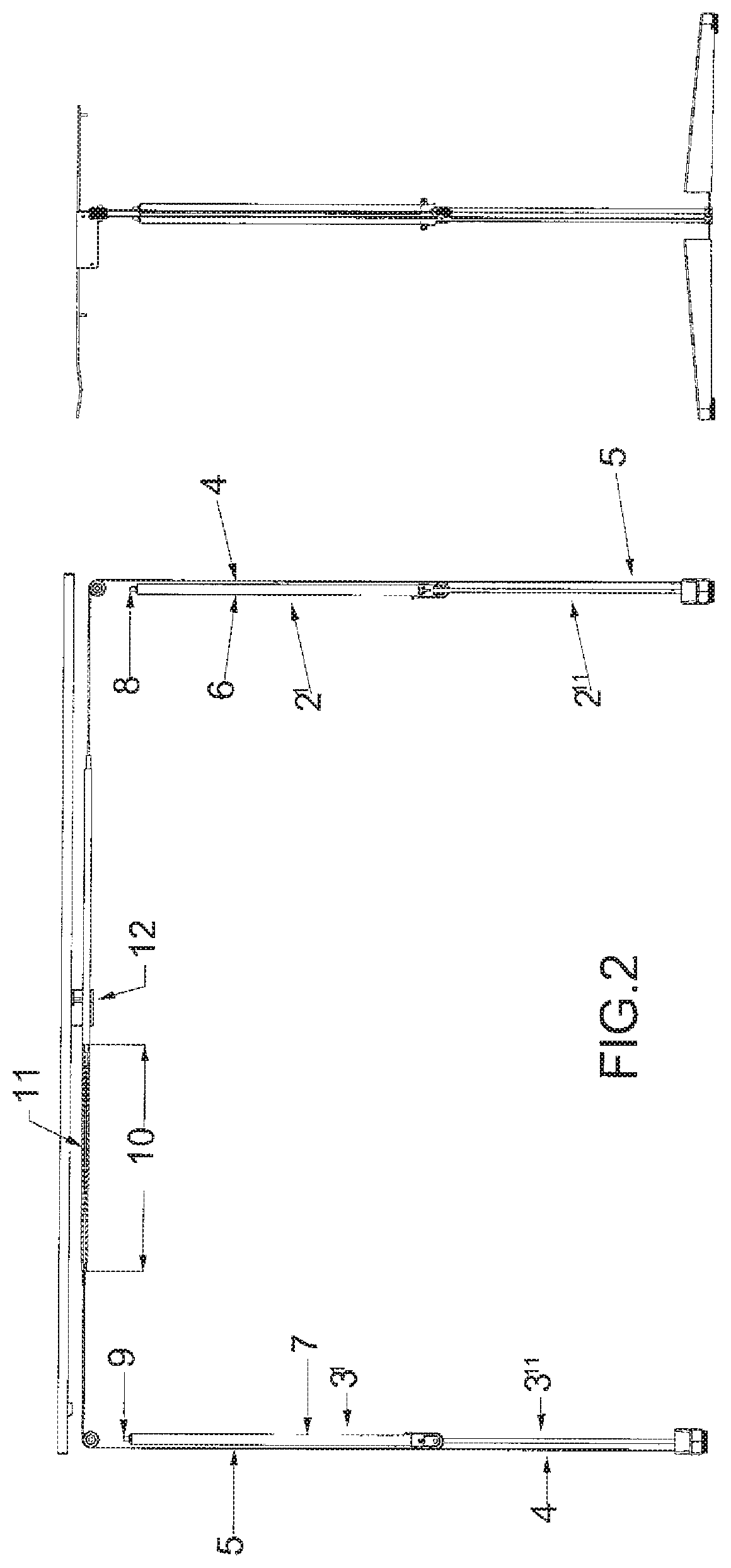
FIG. 2 shows a side view of the frame of FIG. 1, wherein for clarity certain parts are not shown, according to an embodiment of the present invention;
FIG. 3 shows a perspective view of the frame shown in FIG. 2 according to an embodiment of the present invention;
FIG. 4A shows in a perspective view a frame of a second embodiment of a desk or table according to an embodiment of the present invention;
FIG. 4B-4C show detail aspects of a preferred arresting system of the desk or tabletop according to an embodiment of the present invention;
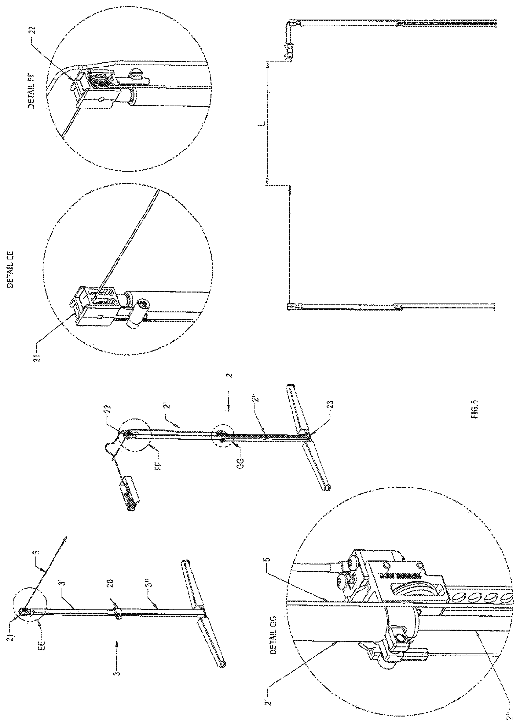
FIGS. 5 and 6 each show separately a single cable that connects to different parts of the left and right leg of the desk or table, when the tabletop is at a high position, according to an embodiment of the present invention;
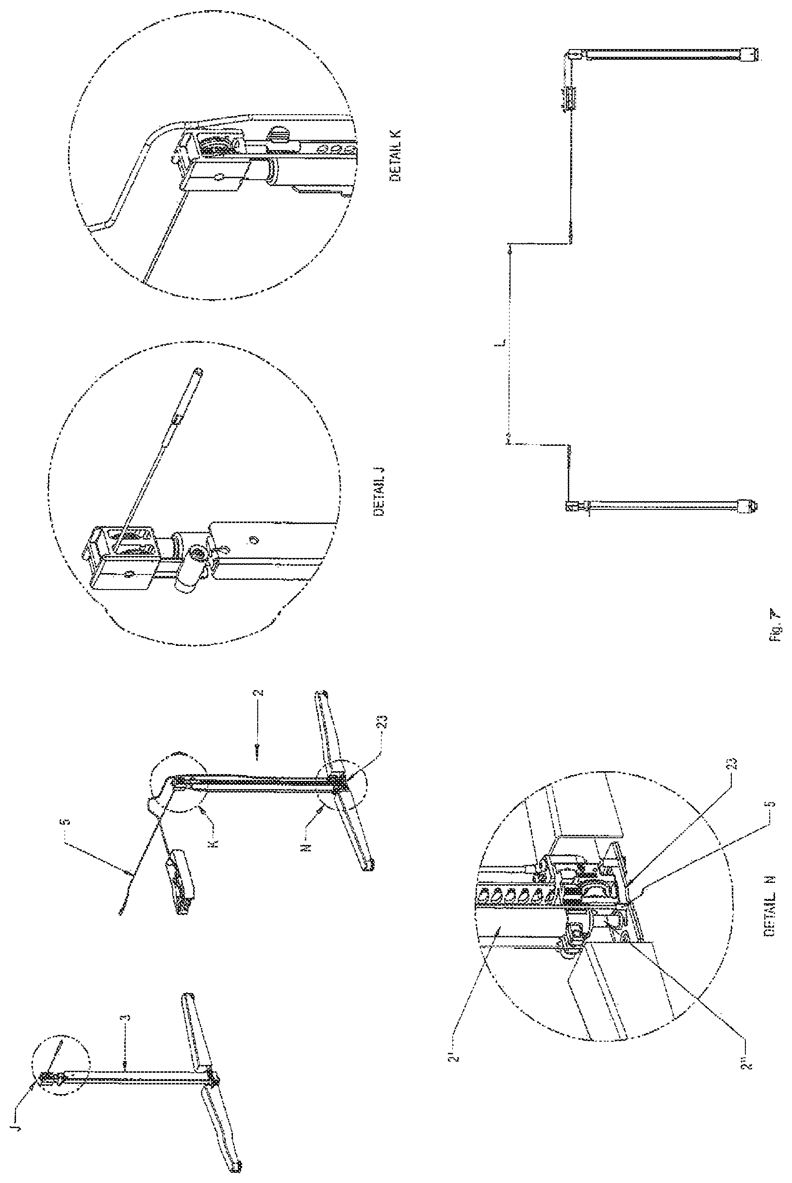
FIGS. 7 and 8 each show separately another single cable that connects different parts of the left and right leg of the desk or table, when the tabletop is at a low position, according to an embodiment of the present invention; and
FIG. 9 shows a perspective view of an arresting system of the desk or tabletop according to an embodiment of the present invention.
DETAILED DESCRIPTION OF THE INVENTION
Whenever in the figures the same reference numerals are applied, these numerals refer to the same parts.
In FIG. 1A a perspective view of a frame 1 of a height adjustable desk or table comprising a desk or tabletop is shown. For clarity the desk or tabletop mounted on top of the frame is not shown, but only the frame 1 itself that supports the desk or tabletop.
FIG. 1B provides a schematic representation of the frame 1 shown in FIG. 1A. The frame 1 preferably comprises spaced apart legs 2, 3 for supporting the desk or tabletop. The legs 2, 3 each have upper portions 2', 3' and lower portions 2'', 3''. The upper portions 2', 3' and the lower portions 2'', 3'' are preferably extendable with respect to each other, and a dual cable linkage 4, 5 is provided at least comprising two separate cables 4 and 5.
With reference to FIG. 1B and FIGS. 6 and 8 it is shown that the first cable 4 is preferably guided via first guide means 14 connected with a lower end 17 of the movable upper portion 2' of the first leg 2 via second guide means 15, 16 to a lower end 18 of the lower stationary portion 3'' of the second leg 3. FIG. 6 shows the relative position of the respective parts of the legs at a highest position of the desk or tabletop, and FIG. 8 shows the relative position of the respective parts of the legs at a lowest position of the desk or tabletop. For clarity only the first cable 4 is shown, and the second cable 5 is not depicted in FIGS. 6 and 8.
With reference to FIG. 1B and FIGS. 5 and 7 it is shown that a second cable b is preferably guided via third guide means 19 connected with a lower end 20 of the movable upper portion 3' of the second leg 3 via fourth guide means 21, 22 to a lower end 23 of the lower stationary portion 2'' of the first leg 2. FIG. 5 shows the relative position of the respective parts of the legs at a highest position of the desk or tabletop, and FIG. 7 shows the relative position of the respective parts of the legs at a lowest position of the desk or tabletop. For clarity only the second cable 5 is shown, and the first cable 4 is not depicted in FIGS. 5 and 7.
This construction as discussed above with reference to FIGS. 1A/B and 5-8 secures that raising and lowering of the upper 2', 3' and lower portions 2'', 3'' of the respective legs 2, 3 is always executed in concert, i.e. both upper 2', 3' portions always move in sync with each other.
Preferably, the upper 2', 3' and lower portions 2'', 3'' of the legs 2, 3 are embodied as gas springs 6, 7. See also FIGS. 2 and 3, wherein a further preferable feature according to the invention is depicted, notably that one or both of the gas springs 6, 7 is provided with a valve 8, 9 to regulate the pressure in the gas springs 6, 7. This is one of the primary innovations of the embodiments of the present invention described in this application.
With reference to both FIG. 1 and FIG. 3 another aspect of an embodiment of the present invention is shown, wherein the cable linkage 4, 5 is preferably provided with a horizontal part 9 extending between the spaced apart legs 2, 3, wherein said horizontal part 9 comprises a section 10 with a corrugated surface or screw thread 11, which section 10 cooperates with an arresting block 12 which is manipulable with a handle 13. The arresting block 12 is capable to fix said section 10 of the horizontal part 9 in a selected position so as to fix the height of the desk or tabletop.
Finally FIG. 4A shows in a perspective view a frame of a second embodiment of a desk or table according to the invention; wherein FIGS. 4B-4C show detail aspects of a preferred arresting system of the desk or table top of the invention, notably that leg 2 is provided with a rail 24 with slots 25, wherein the slots 25 are equipped to receive an arresting pin 28 (housed in housing 26 and therefore not visible) to selectively block movement of the movable upper portion 2' with respect to the lower portion 2'' of said leg 2. FIG. 4B shows the control device 27 at a side of the frame with which control device 27 the said pin 28 can be moved into or out a particular slot 25 of the rail 24. The arresting pin 28 is provided at a stationary position of the lower portion 2'' of the leg 2.
Although the invention has been discussed in the foregoing with reference to an exemplary embodiment of the frame of a height adjustable desk or table according to the invention, the invention is not restricted to this particular embodiment which can be varied in many ways without departing from the invention. The discussed exemplary embodiment shall therefore not be used to construe the appended claims strictly in accordance therewith. On the contrary the embodiment is merely intended to explain the wording of the appended claims without intent to limit the claims to this exemplary embodiment. The scope of protection of the invention shall therefore be construed in accordance with the appended claims only, wherein a possible ambiguity in the wording of the claims shall be resolved using this exemplary embodiment. Note that in the specification and claims, "about" or "approximately" means within twenty percent (20%) of the numerical amount cited.
NOMENCLATURE
1: frame 2: leg; 2': movable upper portion; 2'': stationary lower portion 3: leg; 3': movable upper portion; 3'': stationary lower portion 4: first cable 5: second cable 6: gas spring 7: gas spring 8: valve 9: horizontal part 10: horizontal section 11: screw thread 12: arresting block 13: handle 14: first guide means 15: second guide means 16: second guide means 17: lower end of upper portion first leg 18: lower end of lower portion second leg 19: third guide means 20: lower end of upper portion second leg 21: fourth guide means 22: fourth guide means 23: lower end of lower portion first leg 24: rail 25: slots 26: housing 27: control device
* * * * *
D00000
D00001
D00002
D00003
D00004
D00005
D00006
D00007
D00008
D00009
D00010
XML
uspto.report is an independent third-party trademark research tool that is not affiliated, endorsed, or sponsored by the United States Patent and Trademark Office (USPTO) or any other governmental organization. The information provided by uspto.report is based on publicly available data at the time of writing and is intended for informational purposes only.
While we strive to provide accurate and up-to-date information, we do not guarantee the accuracy, completeness, reliability, or suitability of the information displayed on this site. The use of this site is at your own risk. Any reliance you place on such information is therefore strictly at your own risk.
All official trademark data, including owner information, should be verified by visiting the official USPTO website at www.uspto.gov. This site is not intended to replace professional legal advice and should not be used as a substitute for consulting with a legal professional who is knowledgeable about trademark law.