Microfluidic particle analysis method, device and system
Lee , et al. January 26, 2
U.S. patent number 10,900,886 [Application Number 15/958,480] was granted by the patent office on 2021-01-26 for microfluidic particle analysis method, device and system. This patent grant is currently assigned to EMD Millipore Corporation. The grantee listed for this patent is EMD Millipore Corporation. Invention is credited to Paul Ju-Sung Hung, Philip Janmin Lee, Narendra Maheshri.


View All Diagrams
| United States Patent | 10,900,886 |
| Lee , et al. | January 26, 2021 |
Microfluidic particle analysis method, device and system
Abstract
The method, device, and system relate to particle analysis, and in particular, to a microfluidic device designed for trapping particles for analysis. Particles include beads and cells.
| Inventors: | Lee; Philip Janmin (Alameda, CA), Hung; Paul Ju-Sung (Fremont, CA), Maheshri; Narendra (Cambridge, MA) | ||||||||||
|---|---|---|---|---|---|---|---|---|---|---|---|
| Applicant: |
|
||||||||||
| Assignee: | EMD Millipore Corporation
(Burlington, MA) |
||||||||||
| Appl. No.: | 15/958,480 | ||||||||||
| Filed: | April 20, 2018 |
Prior Publication Data
| Document Identifier | Publication Date | |
|---|---|---|
| US 20180275043 A1 | Sep 27, 2018 | |
Related U.S. Patent Documents
| Application Number | Filing Date | Patent Number | Issue Date | ||
|---|---|---|---|---|---|
| 15163398 | May 24, 2016 | 10054536 | |||
| 12019857 | May 31, 2016 | 9354156 | |||
| 60900651 | Feb 8, 2007 | ||||
| Current U.S. Class: | 1/1 |
| Current CPC Class: | G01N 15/1463 (20130101); B01L 3/502707 (20130101); G01N 15/1459 (20130101); G01N 33/54366 (20130101); B01L 3/502761 (20130101); G01N 15/1484 (20130101); G01N 33/487 (20130101); B01L 2400/0487 (20130101); G01N 2015/0065 (20130101); B01L 2300/0867 (20130101); G01N 2015/1493 (20130101); G01N 15/147 (20130101); G01N 15/1475 (20130101); B01L 2200/0668 (20130101); B01L 2400/0655 (20130101); B01L 2400/0481 (20130101); B01L 2300/123 (20130101) |
| Current International Class: | G01N 15/14 (20060101); G01N 33/487 (20060101); B01L 3/00 (20060101); G01N 33/543 (20060101); G01N 15/00 (20060101) |
References Cited [Referenced By]
U.S. Patent Documents
| 4055613 | October 1977 | Kapral |
| 4661455 | April 1987 | Hubbard |
| 4734373 | March 1988 | Bartal |
| 4748124 | May 1988 | Vogler |
| 5079168 | January 1992 | Amiot |
| 5153131 | October 1992 | Wolf et al. |
| 5310676 | May 1994 | Johansson et al. |
| 5330908 | July 1994 | Spaulding |
| 5376252 | December 1994 | Ekstrom et al. |
| 5416022 | May 1995 | Amiot |
| 5424209 | June 1995 | Kearney |
| 5437998 | August 1995 | Schwarz et al. |
| 5451524 | September 1995 | Coble et al. |
| 5462874 | October 1995 | Wolf et al. |
| 5565353 | October 1996 | Klebe et al. |
| 5589112 | December 1996 | Spaulding |
| 5593814 | January 1997 | Matsuda et al. |
| 5602028 | February 1997 | Minchinton |
| 5627070 | May 1997 | Gruenberg |
| 5637469 | June 1997 | Wilding et al. |
| 5641644 | June 1997 | Klebe |
| 5658797 | August 1997 | Bader |
| 5686301 | November 1997 | Falkenberg et al. |
| 5686304 | November 1997 | Codner |
| 5693537 | December 1997 | Wilson et al. |
| 5702941 | December 1997 | Schwarz |
| 5714384 | February 1998 | Wilson et al. |
| 5763261 | June 1998 | Gruenberg |
| 5763275 | June 1998 | Nagels et al. |
| 5763279 | June 1998 | Schwarz et al. |
| 5786215 | July 1998 | Brown et al. |
| 5793440 | August 1998 | Nakasaka et al. |
| 5801054 | September 1998 | Kiel et al. |
| 5866345 | February 1999 | Wilding et al. |
| 5882918 | March 1999 | Goffe |
| 5900361 | May 1999 | Klebe |
| 5912177 | June 1999 | Turner et al. |
| 5924583 | July 1999 | Stevens et al. |
| 5932315 | August 1999 | Lum et al. |
| 5942443 | August 1999 | Parce et al. |
| 6039897 | March 2000 | Lochhead et al. |
| 6048498 | April 2000 | Kennedy |
| 6096532 | August 2000 | Armstrong et al. |
| 6107085 | August 2000 | Coughlin et al. |
| 6153073 | November 2000 | Dubrow et al. |
| 6190913 | February 2001 | Singh |
| 6197575 | March 2001 | Griffith et al. |
| 6228635 | May 2001 | Armstrong et al. |
| 6238908 | May 2001 | Armstrong et al. |
| 6251343 | June 2001 | Dubrow et al. |
| 6274337 | August 2001 | Parce et al. |
| 6277642 | August 2001 | Mentzen et al. |
| 6297046 | October 2001 | Smith et al. |
| 6323022 | November 2001 | Chang et al. |
| 6326211 | December 2001 | Anderson et al. |
| 6403369 | June 2002 | Wood |
| 6410309 | June 2002 | Barbera-Guillem et al. |
| 6455310 | September 2002 | Barbera-Guillem |
| 6465243 | October 2002 | Okada et al. |
| 6468792 | October 2002 | Bader |
| 6481648 | November 2002 | Zimmerman |
| 6495104 | December 2002 | Unno et al. |
| 6518035 | February 2003 | Ashby et al. |
| 6534013 | March 2003 | Kennedy |
| 6548263 | April 2003 | Kapur et al. |
| 6551841 | April 2003 | Wilding et al. |
| 6555365 | April 2003 | Barbera-Guillem et al. |
| 6562616 | May 2003 | Toner et al. |
| 6569675 | May 2003 | Wall et al. |
| 6576458 | June 2003 | Sarem et al. |
| 6585744 | July 2003 | Griffith |
| 6585939 | July 2003 | Dapprich |
| 6593136 | July 2003 | Geiss |
| 6637463 | October 2003 | Lei et al. |
| 6648015 | November 2003 | Chow |
| 6653124 | November 2003 | Freeman |
| 6673595 | January 2004 | Barbera-Guillem |
| 6756019 | June 2004 | Dubrow et al. |
| 6759245 | July 2004 | Toner et al. |
| 6794184 | September 2004 | Mohr et al. |
| 6811752 | November 2004 | Barbera-Guillem |
| 6821772 | November 2004 | Barbera-Guillem et al. |
| 6846668 | January 2005 | Garman et al. |
| 6857449 | February 2005 | Chow |
| 6908767 | June 2005 | Bader |
| 6915679 | July 2005 | Chien et al. |
| 6969166 | November 2005 | Clark et al. |
| 7005292 | February 2006 | Wilding et al. |
| 7018830 | March 2006 | Wilding et al. |
| 7022518 | April 2006 | Feye |
| 7067263 | June 2006 | Parce et al. |
| 7141386 | November 2006 | Dunfield et al. |
| 7155344 | December 2006 | Parce et al. |
| 7160687 | January 2007 | Kapur et al. |
| 7171983 | February 2007 | Chien et al. |
| 7192769 | March 2007 | Pykett et al. |
| 7223371 | May 2007 | Hayenga et al. |
| 7343248 | March 2008 | Parce et al. |
| 7745209 | June 2010 | Martin et al. |
| 7919319 | April 2011 | Jervis et al. |
| 8257964 | September 2012 | Hung et al. |
| 8673625 | March 2014 | Hung et al. |
| 8709790 | April 2014 | Hung et al. |
| 9206384 | December 2015 | Lee et al. |
| 9260688 | February 2016 | Hung et al. |
| 9353342 | May 2016 | Hung et al. |
| 9353343 | May 2016 | Hung et al. |
| 9354156 | May 2016 | Lee |
| 9371929 | June 2016 | Hung et al. |
| 9376658 | June 2016 | Hung et al. |
| 9388374 | July 2016 | Hung et al. |
| 9428723 | August 2016 | Lee et al. |
| 9637715 | May 2017 | Hung et al. |
| 10054536 | August 2018 | Lee et al. |
| 10138453 | November 2018 | Hung et al. |
| 10174278 | January 2019 | Hung et al. |
| 10179897 | January 2019 | Hung et al. |
| 10190085 | January 2019 | Lee et al. |
| 2002/0039785 | April 2002 | Schroeder et al. |
| 2002/0108860 | August 2002 | Staats |
| 2002/0110905 | August 2002 | Barbera-Guillem et al. |
| 2002/0177221 | November 2002 | Nishiguchi et al. |
| 2003/0003571 | January 2003 | Kanegasaki |
| 2003/0008388 | January 2003 | Barbera-Guillem et al. |
| 2003/0008389 | January 2003 | Carll |
| 2003/0030184 | February 2003 | Kim et al. |
| 2003/0040104 | February 2003 | Barbera-Guillem |
| 2003/0124623 | July 2003 | Yager et al. |
| 2003/0143727 | July 2003 | Chang |
| 2003/0156992 | August 2003 | Anderson et al. |
| 2003/0211012 | November 2003 | Bergstrom et al. |
| 2003/0215941 | November 2003 | Campbell et al. |
| 2004/0029266 | February 2004 | Barbera-Guillem |
| 2004/0043481 | March 2004 | Wilson |
| 2004/0072278 | April 2004 | Chou et al. |
| 2004/0096960 | May 2004 | Burd Mehta |
| 2004/0132175 | July 2004 | Vetillard et al. |
| 2004/0202579 | October 2004 | Larsson et al. |
| 2004/0229349 | November 2004 | Daridon |
| 2004/0238484 | December 2004 | Le Pioufle et al. |
| 2005/0009179 | January 2005 | Gemmiti et al. |
| 2005/0019213 | January 2005 | Kechagia et al. |
| 2005/0032208 | February 2005 | Oh et al. |
| 2005/0101009 | May 2005 | Wilson et al. |
| 2005/0106717 | May 2005 | Wilson et al. |
| 2005/0072946 | July 2005 | Studer et al. |
| 2005/0169962 | August 2005 | Bhatia et al. |
| 2005/0214173 | September 2005 | Facer et al. |
| 2005/0221373 | October 2005 | Enzelberger |
| 2005/0260745 | November 2005 | Domansky et al. |
| 2005/0266582 | December 2005 | Modlin et al. |
| 2006/0003436 | January 2006 | DiMilla et al. |
| 2006/0031955 | February 2006 | West et al. |
| 2006/0112438 | May 2006 | West et al. |
| 2006/0121606 | June 2006 | Ito et al. |
| 2006/0136182 | June 2006 | Vacanti et al. |
| 2006/0141617 | June 2006 | Desai et al. |
| 2006/0154361 | July 2006 | Wikswo et al. |
| 2006/0166354 | July 2006 | Wikswo et al. |
| 2006/0199260 | September 2006 | Zhang et al. |
| 2007/0026516 | February 2007 | Martin et al. |
| 2007/0084706 | April 2007 | Takayama et al. |
| 2007/0090166 | April 2007 | Takayama et al. |
| 2007/0122314 | May 2007 | Strand et al. |
| 2007/0128715 | June 2007 | Vukasinovic et al. |
| 2007/0243523 | October 2007 | Ionescu-Zanetti et al. |
| 2007/0264705 | November 2007 | Dodgson |
| 2007/0275455 | November 2007 | Hung et al. |
| 2008/0032380 | February 2008 | Kleis et al. |
| 2008/0038713 | February 2008 | Gao et al. |
| 2008/0085556 | April 2008 | Graefing et al. |
| 2008/0176318 | July 2008 | Wilson et al. |
| 2008/0194012 | August 2008 | Lee et al. |
| 2008/0227176 | September 2008 | Wilson |
| 2008/0233607 | September 2008 | Yu et al. |
| 2008/0261295 | October 2008 | Butler et al. |
| 2009/0023608 | January 2009 | Hung et al. |
| 2009/0123961 | May 2009 | Meyvantsson et al. |
| 2009/0148933 | June 2009 | Battrell et al. |
| 2009/0203126 | August 2009 | Hung et al. |
| 2009/0221073 | September 2009 | Toner |
| 2010/0151571 | June 2010 | Vukasinovic et al. |
| 2010/0196908 | August 2010 | Opalsky et al. |
| 2010/0234674 | September 2010 | Wheeler et al. |
| 2012/0003732 | January 2012 | Hung et al. |
| 2012/0164036 | June 2012 | Stern et al. |
| 2013/0059322 | March 2013 | Hung et al. |
| 2013/0081757 | April 2013 | Hung et al. |
| 2013/0090268 | April 2013 | Hung et al. |
| 2013/0171679 | July 2013 | Lee et al. |
| 2013/0171682 | July 2013 | Hung et al. |
| 2014/0057311 | February 2014 | Kamm et al. |
| 2014/0090735 | April 2014 | Hung et al. |
| 2014/0099705 | April 2014 | Hung et al. |
| 2014/0287489 | September 2014 | Lee et al. |
| 2016/0075984 | March 2016 | Hung et al. |
| 2016/0289623 | October 2016 | Hung et al. |
| 2016/0312166 | October 2016 | Lee et al. |
| 2016/0327470 | November 2016 | Lee et al. |
| 2016/0333297 | November 2016 | Hung et al. |
| 2016/0333298 | November 2016 | Hung et al. |
| 2016/0340630 | November 2016 | Hung et al. |
| 2017/0267961 | September 2017 | Hung et al. |
| 201803927 | Apr 2011 | CN | |||
| 19948087 | May 2001 | DE | |||
| 0155237 | Sep 1985 | EP | |||
| 0725134 | Aug 1996 | EP | |||
| 0890636 | Jan 1999 | EP | |||
| 1539263 | Jan 1979 | GB | |||
| 91/15570 | Oct 1991 | WO | |||
| 00/56870 | Sep 2000 | WO | |||
| 00/60352 | Oct 2000 | WO | |||
| 00/78932 | Dec 2000 | WO | |||
| 01/92462 | Dec 2001 | WO | |||
| 03/085080 | Oct 2003 | WO | |||
| 03/098218 | Nov 2003 | WO | |||
| 2004/059299 | Jul 2004 | WO | |||
| 2004/106484 | Dec 2004 | WO | |||
| 2005/035728 | Apr 2005 | WO | |||
| 2007/008606 | Jan 2007 | WO | |||
| 2007/008609 | Jan 2007 | WO | |||
| 2009/089189 | Jul 2009 | WO | |||
| 2009/102453 | Aug 2009 | WO | |||
| 2012/024646 | Feb 2012 | WO | |||
Other References
|
Notice of allowance dated Jul. 20, 2018 in co-pending U.S. Appl. No. 15/163,368. cited by applicant . Notice of allowance dated Aug. 6, 2018 in co-pending U.S. Appl. No. 15/161,665. cited by applicant . Office action dated May 20, 2019 in co-pending U.S. Appl. No. 15/459,332. cited by applicant . Final rejection dated Jan. 23, 2019 in co-pending U.S. Appl. No. 15/175,749. cited by applicant . European communication dated Apr. 3, 2012 in co-pending European patent application No. 06786499.1. cited by applicant . International Search Report and Written Opinion dated Apr. 9, 2009 in PCT application No. PCT/US06/26364 (corresponding to U.S. Appl. No. 11/994,997). cited by applicant . International Search Report and Written Opinion dated Jul. 30, 2009 in co-pending PCT application No. PCT/US2009/030168. cited by applicant . European communication dated Oct. 21, 2013 in co-pending European patent application No. 09701350.2. cited by applicant . International Search Report dated May 14, 2013 in co-pending PCT application No. PCT/US2013/024999. cited by applicant . International Search Report dated Mar. 19, 2013 in co-pending PCT application No. PCT/US2012/067632. cited by applicant . International Preliminary Report on Patentability dated Jun. 12, 2014 in co-pending PCT application no. PCT/US2012/067632. cited by applicant . Eurpoean communication dated Jul. 28, 2015 in co-pending European patent application No. 12852539.1. cited by applicant . Japanese communication, with English translation, dated Nov. 17, 2015 in co-pending Japanese patent application No. 2015-503203. cited by applicant . Chinese communication, with English translation, dated Jun. 20, 2016 in co-pending Chinese patent application No. 201380018324.1 cited by applicant . Engineering Aspects of Food Biotechnology, Chapter 5, CRC Press: Boca Raton, FL, 2004, copyright 2014, p. 127, "Meet the Stem Cells; Production of Cultured Meat from a Stem Cell Biology Perspective", Brinkhof, et al., 3 pages. cited by applicant . Cellasic Corporation, ONIX Application Note, "Microincubator for long term live cell microscopy", Feb. 3, 2012, pp. 1-4. cited by applicant . Optics Express, vol. 14, No. 13, Jun. 2006, pp. 6253-6256, "Fabrication of polymer microlens arrays using capillary forming with a soft mold of micro-holes array and UV-curable polymer", Chang, et al. cited by applicant . Lab Chip, 2007, vol. 7, pp. 641-643, published by the Royal Society of Chemistry, "Rapid fabrication of microchannels using microscale plasma activated templating (uPLAT) generated water molds", Chao, et al. cited by applicant . Lab on a Chip, 2007, vol. 7, pp. 763-769, "A hydrogel-based microfluidic device for the studies of directed cell migration", Cheng, et al. cited by applicant . Lab Chip, 2005, vol. 5, No. 4, pp. 401-406, published by the Royal Society of Chemistry, "Human neural stem growth and differentiation in a gradient-generating microfluidic device", Chung, et al. cited by applicant . Lab on a Chip, 2008, vol. 9, Iss.2 pp. 269-275, "Cell Migration into Scaffolds Under Co-culture Conditions in a Microfluidic Platform," Chung et al. cited by applicant . J. Biochem., vol. 130, pp. 367-376, (2001), "A Method for Micrometer Resolution Patterning of Primary Culture Neurons for SPM Analysis", Degenaar, et al. cited by applicant . Biotechnology and Bioengineering, vol. 89, No. 1, Jan. 5, 2005, pp. 1-8, "Continuous Perfusion Microfluidic Cell Culture Array for High-Throughput Cell-Based Assays", Hung, et al. cited by applicant . Lab Chip, 2005, vol. 5, pp. 44-48, "A novel high aspect ratio microfluidic design to provide a stable and uniform microenvironment for cell growth in a high throughput mammalian cell culture array", Hung, et al. cited by applicant . Lab Chip, 2008, vol. 8, No. 1, pp. 34-57, published by the Royal Society of Chemistry, "Biomolecular gradients in cell culture systems", Keenan, et al. cited by applicant . Keenan et al., "A new method for studying gradient-induced neutrophil desensitization based on an open microfluidic chamber", Lab Chip, 2010, vol. 10, pp. 116-122. cited by applicant . Lab on a Chip, 2009, vol. 9, p. 1797-1800, "Selective and tunable gradient device for cell culture and chemotaxis study", Kim, et al. cited by applicant . Biotechnology and Bioengineering, vol. 97, No. 5, Aug. 1, 2007, pp. 1340-1346, "An Artificial Liver Sinusoid With a Microfluidic Endothelial-Like Barrier for Primary Hepatocyte Culture", Lee, et al. cited by applicant . Lab Chip, 2009, vol. 9, No. 1, pp. 164-166, published by the Royal Society of Chemistry, "Dynamic cell culture: a microfluidic function generator for live cell microscopy", Lee, et al. cited by applicant . Journal of the Association for Laboratory Automation (JALA), 2007, vol. 12, No. 6, pp. 363-367, "Microfluidic System for Automated Cell-Based Assays", Lee, et al. cited by applicant . Lee et al., "Microfluidic Systems for Live Cell Imaging", Methods in Cell Biology, 2011, vol. 102, pp. 77-103. cited by applicant . Lab Chip, 2003, vol. 3, pp. 318-323, published by the the Royal Society of Chemistry, "Fabrication of microfluidic mixers and artificial vasculatures using a high-brightness diode-pumped Nd: YAG laser direct write method", Lim, et al. cited by applicant . Biomed Microdevices (2008), vol. 10, pp. 499-507, "Microfluidic switching system for analyzing chemotaxis responses of wortmannin-inhibited HL-60 cells", Liu, et al. cited by applicant . Biomaterials, 2008, vol. 29, No. 22, pp. 3237-3244, "A gel-free 3D microfluidic cell culture system", Ong, et al. cited by applicant . Lab on a Chip, 2007, vol. 7, pp. 1673-1680, "Gradient generation by an osmotic pump and the behavior of human mesenchymal stem cells under the fetal bovine serum concentration gradient", Park, et al. cited by applicant . Angew. Chem. Int. Ed., 2004, vol. 43, pp. 1531-1536, "Minimal Functional Model of Hemostasis in a Biomimetic Microfluidic System", Runyon, et al. cited by applicant . Biomedical Microdevices, 2003, vol. 5, No. 3, pp. 235-244, "Microfluidic Patterning of Cellular Biopolymer Matrices for Biomimetic 3-D Structures", Tan, et al. cited by applicant . Office action dated Apr. 18, 2018 in co-pending U.S. Appl. No. 15/175,449. cited by applicant . Office action dated Feb. 20, 2018 in co-pending U.S. Appl. No. 15/163,398. cited by applicant . Ex Parte Quayle action mailed Apr. 24, 2018 in co-pending U.S. Appl. No. 15/163,398. cited by applicant . Notice of allowance dated Jun. 11, 2018 in co-pending U.S. Appl. No. 15/163,398. cited by applicant . Office action dated Apr. 11, 2018 in co-pending U.S. Appl. No. 15/163,368. cited by applicant . Office action dated Feb. 23, 2017 in co-pending U.S. Appl. No. 15/175,749. cited by applicant . Office action dated Nov. 1, 2017 in co-pending U.S. Appl. No. 15/175,749. cited by applicant . Final rejection dated Mar. 27, 2018 in co-pending U.S. Appl. No. 15/175,749. cited by applicant . Office action dated Jul. 10, 2018 in co-pending U.S. Appl. 15/175,749. cited by applicant . Office action dated Mar. 21, 2018 in co-pending U.S. Appl. No. 15/163,818. cited by applicant . Ex Parte Quayle action mailed May 21, 2018 in co-pending U.S. Appl. No. 15/163,818. cited by applicant . Notice of allowance dated Jul. 5, 2018 in co-pending U.S. Appl. No. 15/163,818. cited by applicant . Office action dated Jul. 6, 2017 in co-pending U.S. Appl. No. 15/161,665. cited by applicant . Notice of allowance dated Feb. 2, 2018 in co-pending U.S. Appl. No. 15/161,665. cited by applicant . Notice of allowance dated May 31, 2018 in co-pending U.S. Appl. No. 15/161,665. cited by applicant . Notice of allowance dated Aug. 27, 2019 in co-pending U.S. Appl. No. 15/459,332. cited by applicant . Notice of allowance dated Sep. 12, 2018 in co-pending U.S. Appl. No. 15/175,449. cited by applicant. |
Primary Examiner: Hobbs; Michael L
Attorney, Agent or Firm: Nields, Lemack & Frame, LLC
Parent Case Text
This application is a continuation of U.S. patent application Ser. No. 15/163,398 filed May 24, 2016, (now U.S. Pat. No. 10,054,536 issued Aug. 1, 2018) which is a continuation of U.S. patent application Ser. No. 12/019,857 filed Jan. 25, 2008 (now U.S. Pat. No. 9,354,156 issued May 31, 2016), which claims priority to U.S. Provisional Patent Application No. 60/900,651 filed on Feb. 8, 2007, which is incorporated herein in its entirety by reference.
Claims
It is claimed:
1. A microfluidic particle analysis device comprising: a microfluidics body having a bottom surface; a particle inlet port; a microfluidics channel in said body holding a fluid flow of a liquid containing one or more cell-sized particles, said fluid flow provided via the particle inlet port in communication with a first end of said microfluidics channel; a solution inlet port; a solution outlet port; a secondary microchannel in fluid communication with said solution inlet port, said solution outlet port and a second end of said microfluidics channel; and at least one trapping region in said microfluidics channel between said first end and said second end, said at least one trapping region comprising a deformable wall portion with a cavity therein, configured to have two operational heights when subjected to two different operational pressures, the two operational heights of the deformable wall portion, comprising: a first height configured to allow one or more cell-sized particles of interest to pass between the deformable wall portion and said bottom surface into said cavity via said fluid flow in said channel; and a second height configured to trap one or more cell-sized particles of a given size within said cavity of trapping region of said channel by reducing a dimension between the deformable wall portion and said bottom surface so that the cell-sized particles cannot exit the cavity; wherein, at the two operational heights, the cell-sized particles disposed in the trapping zone remain in fluid communication with the secondary microchannel.
2. The device of claim 1, wherein the second height of said deformable wall portion comprises a relaxed condition, at which particles of a selected size are prevented from entering the trapping region, and said first height comprises an expanded position at which particles of said selected size may enter and flow through the trapping region.
3. The device of claim 1, further comprising a microfluidic mesh in fluid contact with the microfluidic channel, wherein the mesh prevents the passage of particles from the microfluidic channel to a channel downstream of said trapping region.
4. The device of claim 1, wherein the microfluidic channel has a plurality of longitudinally spaces trapping regions, each defined by a respective deformable wall portion and cavity, each trapping region configured to trap particles of a different size.
5. The device of claim 1, wherein said two different operational pressures are provided by pneumatic pressure delivered to said port.
6. The device of claim 1, wherein said two different operational pressures are provided by modifying a pressure at an outside surface of the deformable wall portion.
7. The device of claim 1, wherein the deformable wall portion is formed of a deformable polymer selected from the group consisting of polydimethylsiloxane (PDMS), polyisoprene, polybutadiene, polychloroprene, polyisobutylene, poly(styrene-butadiene-styrene), polyurethane, and silicone.
8. The device of claim 1, wherein the deformable wall portion comprises an extended portion on each opposite end of the cavity, and wherein an entirety of the deformable wall portion moves between the first height and the second height, such that a difference in height between the extended portions and the cavity remains constant.
9. A method of analyzing cells comprising: flowing fluid comprising one or more cell-sized particles of interest in a microfluidics channel, the channel being part of a microfluidics body, the microfluidics body further comprising a particle inlet port in communication with a first end of said microfluidics channel; a solution inlet port; a solution outlet port; a secondary microchannel in fluid communication with said solution inlet port, said solution outlet port and a second end of said microfluidics channel; and at least one trapping region in said microfluidics channel between said first end and said second end, said at least one trapping region comprising a deformable wall portion configured to have two operational heights when subjected to two different operational pressures; applying a first operational pressure to the deformable wall portion to allow the one or more cell-sized particles of interest to pass into said trapping region via said fluid flow in said channel; and applying a second operational pressure to the deformable wall portion to trap one or more cell-sized particles of a given size within said trapping region of said channel; wherein, at the two operational heights, the cell-sized particles disposed in the trapping zone remain in fluid communication with the secondary microchannel.
10. The method of claim 9, wherein said two different operational pressures are provided by pneumatic pressure delivered to said port.
11. The method of claim 9, wherein said two different operational pressured are provided by modifying a pressure at an outside surface of the deformable wall portion.
12. The method of claim 9, wherein the deformable wall comprises a cavity, and wherein the cell-sized particles are trapped in the cavity when the deformable wall is at the second height.
13. The method of claim 9, wherein the deformable wall portion comprises an extended portion on each opposite end of the cavity, and wherein an entirety of the deformable wall portion moves between the first height and the second height, such that a difference in height between the extended portions and the cavity remains constant.
14. The device of claim 1, further comprising an additional port in fluid contact with the particle inlet port, disposed proximate the first end of the microfluidic channel.
Description
FIELD
The device and method relate to microfluidic particle analysis. The device is designed for trapping particles for solution analysis. Exemplary particles include beads and cells.
BACKGROUND
Particle-based science and technology is an important aspect of biomedical and clinical research. Inorganic particles such as quantum dots and beads have found applications in bio-imaging and point-of-care diagnosis. These particles can further be conjugated with other materials such as proteins or DNAs for biosensors and bioassays. Living particles such as cells, viruses and bacteria are commonplace in everyday biological experiments. Through analysis of their molecular and cellular properties using techniques such as DNA sequencing, protein mapping and high content screening, these particles have greatly advanced the development of the biological sciences.
The most common particle analysis apparatus is the flow cytometer, where particles with fluorescent tags are hydrodynamically focused into a stream and excited by laser beams. The emitted fluorescence from the tags are collected by photodetectors and analyzed to extrapolate information about the biological properties of each individual particle. There are three major drawbacks of the system: 1) the system is expensive and bulky. 2) the particles can not be analyzed over time due to the single pass nature of the flow cytometer. 3) it does not resolve subcellular localization of fluorescent signals.
In order to conduct detailed analysis of the particles, it is desired to trap these particles in specific locations so they don't displace due to the forces of fluid flow, shear stress or thermal agitation during the course of the experiment. Microfluidic devices are ideal candidates for particle analysis because of their compact size, low reagent consumption and laminar flow nature. One common method of trapping particles is to use dielectrophoresis, where electrodes and electric fields are used to generate dielectrophoretic forces on particles; however, the particles trapped using this method can still rotate, and are subject to displacement when flows are introduced. In addition, the fabrication of electrodes into the device significantly increases the cost. Using a sieve at a size smaller than the particles can serve as a particle trap; however, the particles will be packed into clumps, making it difficult to analyze.
The potential advantages of a trapped particle array device have been realized to a limited extent in the prior art. Various limitations associated with prior art devices include (i) difficulty in preventing microfluidic structures from being blocked by particles within the structures, (ii) inability to trap the particles so they won't be displaced by fluidic flows, (iii) inability to provide different solutions to the particles at different times for rapid assay.
It would therefore be desirable to provide a microfluidic particle trapping device capable of more fully realizing the advantages noted above in a high throughput particle analysis system.
SUMMARY
In one aspect, a microfluidic particle analysis device is provided comprising
a microfluidics body,
formed in said body, a microfluidics channel for receiving particles at an upstream region thereof,
the channel having a deformable wall portion that defines a particle-capture region, and which is responsive to a change in fluid pressure applied thereto, to selectively vary the particle-flow dimensions of said capture region,
wherein particles having a given size may be selectively retained in said capture region.
In one embodiment, the deformable wall portion is expandable in response to a positive fluid pressure applied within the channel. In another embodiment, said deformable wall portion is expandable in response to a negative pressure applied to a cavity communicating with said wall portion, external to said channel. In some embodiments, said wall portion is deformable from a relaxed condition, at which particles of a selected size are prevented from entering the particle capture region, to a first expanded position at which particles of a selected size may enter and flow through the capture region.
In a particular embodiment, said capture region is defined by a cavity in said deformable wall portion, movement of the wall portion from its relaxed to its first expanded condition allows particles of a selected size to enter and flow through said cavity, and movement of said wall portion from its first expanded condition to its relaxed condition allows such particles to be trapped within said cavity in said capture region.
In another particular embodiment said wall portion is deformable from a relaxed condition, at which particles of a selected size are prevented from entering the particle capture region, to a first expanded position at which particles of a selected size may enter the capture region, and from the first expanded condition to a second expanded position in which the particles become trapped within said capture region.
Some embodiments comprise a microfluidic mesh in fluid contact with the microfluidic passageway, wherein the mesh prevents the passage of particles from the microfluidic passageway to a channel outlet downstream of the particle capture region. Some embodiments include an array of such channels and associated wall portions. In some embodiments, the microfluidic passageway has a plurality of longitudinally spaced capture regions, each defined by a deformable wall portion, and designed for trapping particles of different diameters.
The deformable wall portion is formed of a deformable polymer selected from the group consisting of polydimethylsiloxane (PDMS), polyisoprene, polybutadiene, polychloroprene, polyisobutylene, poly(styrene-butadiene-styrene), polyurethane, and silicone.
In some embodiments, the selectively retained (trapped) particles are addressed with a solution. In other embodiments, the selectively retained particles are addressed with a plurality of solutions in series. In particular embodiments, the solution comprises a drug, a reagent, a nutrient, blood, or serum.
In some embodiments, the solution displaces the selectively retained particles by no more than 10% of the size of the particles. In some embodiments, the solution provides fluid exchange in less than 10 seconds.
In another aspect, methods are provided for trapping particles using a microfluidic channel having a deformable wall portion.
These and other objects and features of the invention will become more fully understood when the following detailed description of the invention is read in conjunction with the accompanying drawings.
BRIEF DESCRIPTION OF THE FIGURES
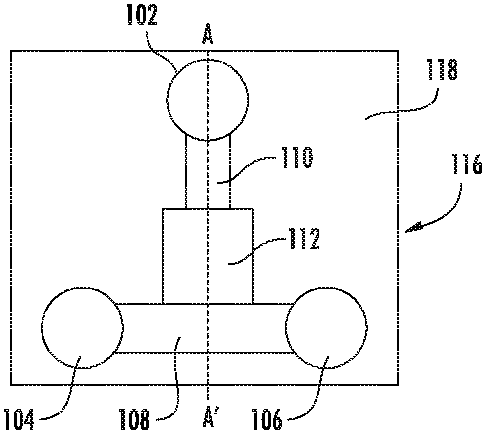
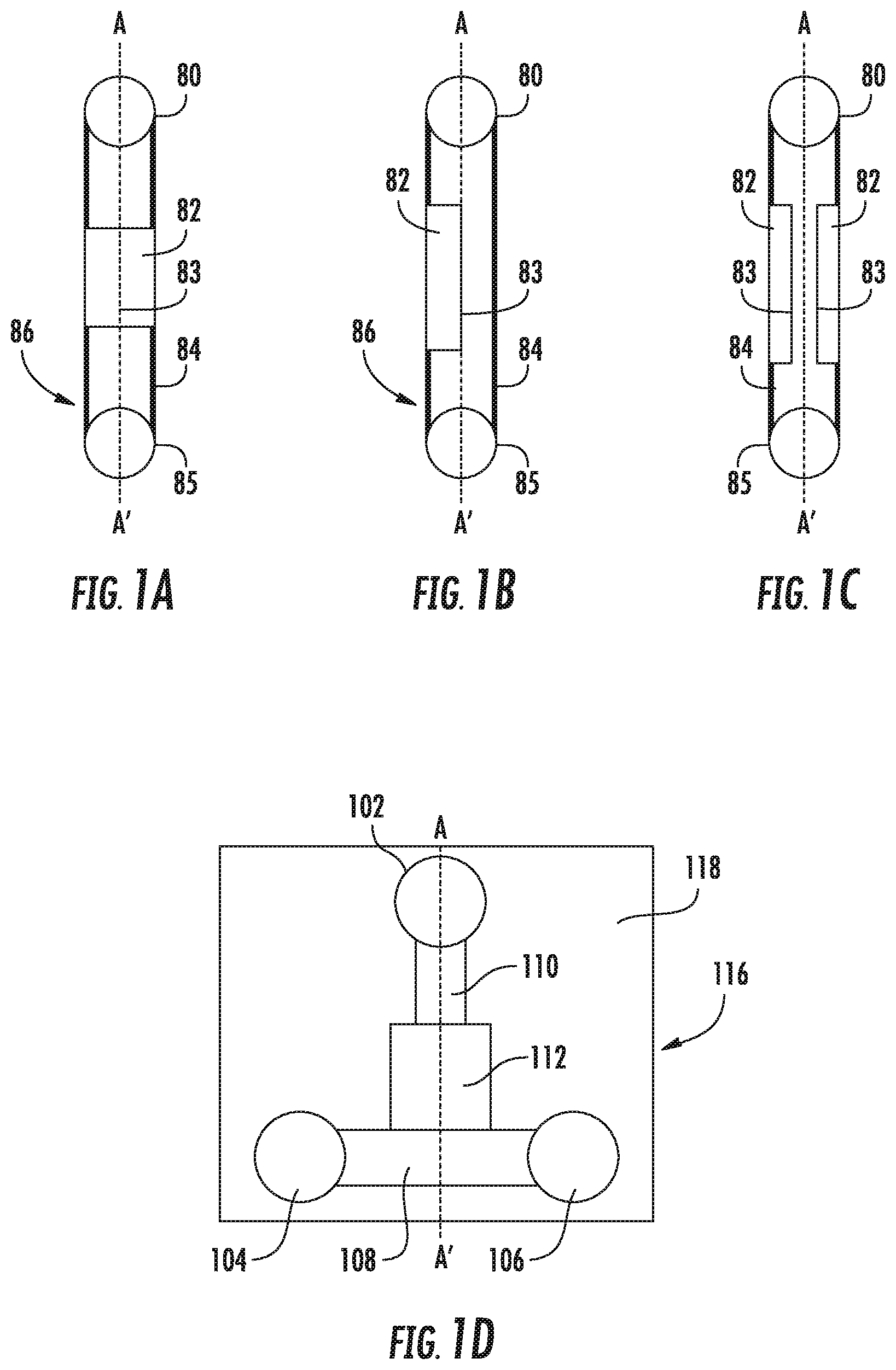
FIGS. 1A-C show a top (FIG. 1A) and side (FIGS. 1B and 1C) views of a microfluidic particle trapping device with a cross-section defined by the line A-A'. FIG. 1D shows a plan view of an embodiment of the microfluidic particle trapping device with three reservoirs and a cross-section defined by the line A-A'
FIGS. 2A-2C show cross-sectional views (A-A' in FIGS. 1A-1D) of an embodiment of the microfluidic particle trapping device in different stages of operation, and having a microfluidic channel of height H', and trapping region internal dimension of height h'. (FIG. 2A) The deformable wall portion is in the relaxed condition, wherein the particle flow dimension (i.e., internal dimension h) is less than the diameter of the particles. (FIG. 2B) The deformable wall portion is in the expanded condition, wherein the particle flow dimension is greater than the particle diameter, allowing the particles to enter the microfluidic channel. (FIG. 2C) The deformable wall portion in the relaxed condition to trap the particles in the microfluidic channel.
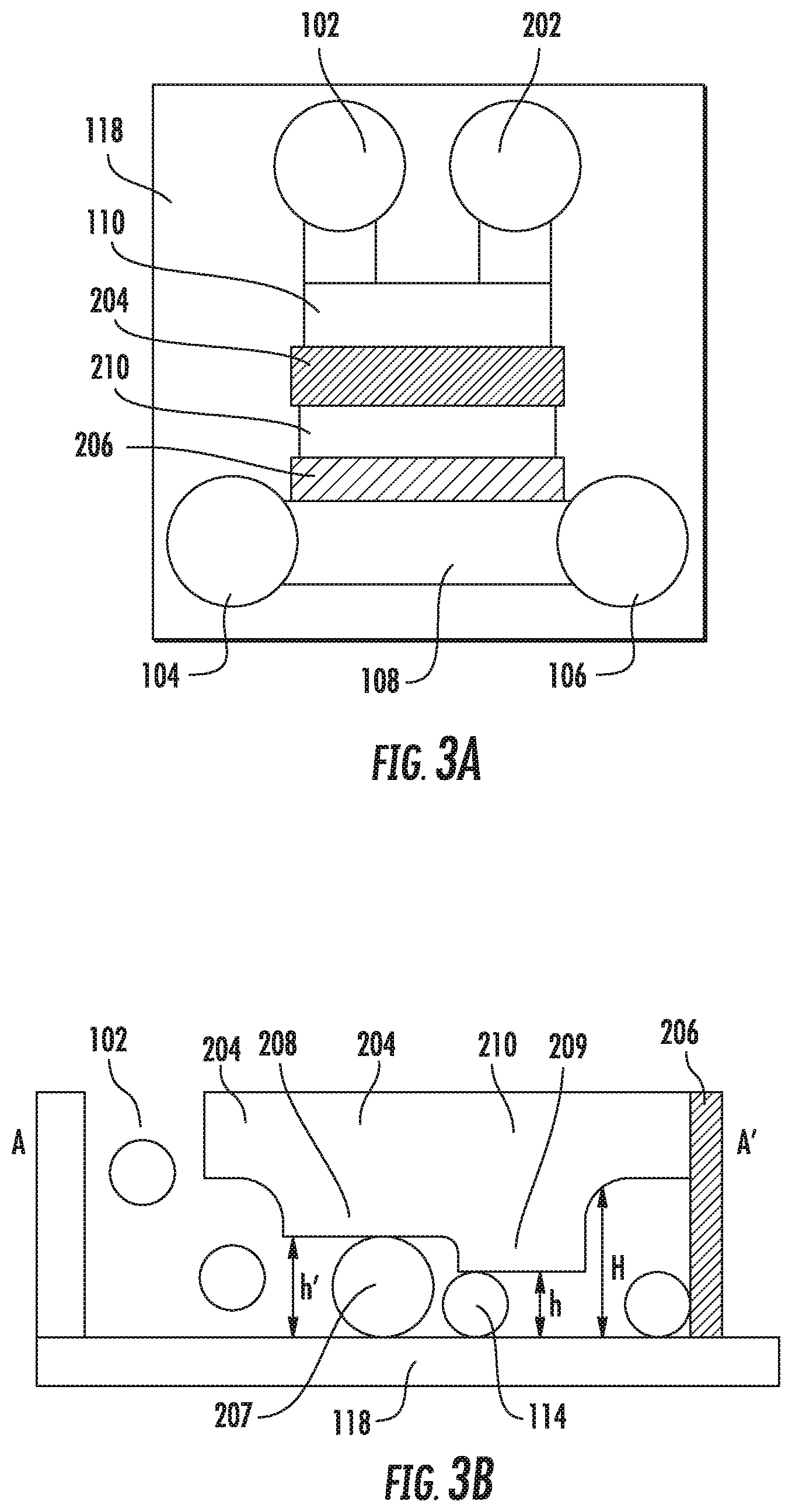
FIGS. 3A and 3B show an embodiment of the device with an additional particle outlet port, multiple trapping regions with different heights, and a sieve to prevent particles from entering the solution ports. (FIG. 3A) Plan view. (FIG. 3B) Cross-section A-A'.
FIGS. 4A and 4B show cross-sectional views of an embodiment of the device in different stages of operation, and having a deformable wall with a cavity. (FIG. 4A) The device is at the first pneumatic pressure to show that the internal dimension (h') is greater than the diameter of the particles. (FIG. 4B) The device is at the second pneumatic to trap the particles in the cavity of the deformable the deformable wall portion.
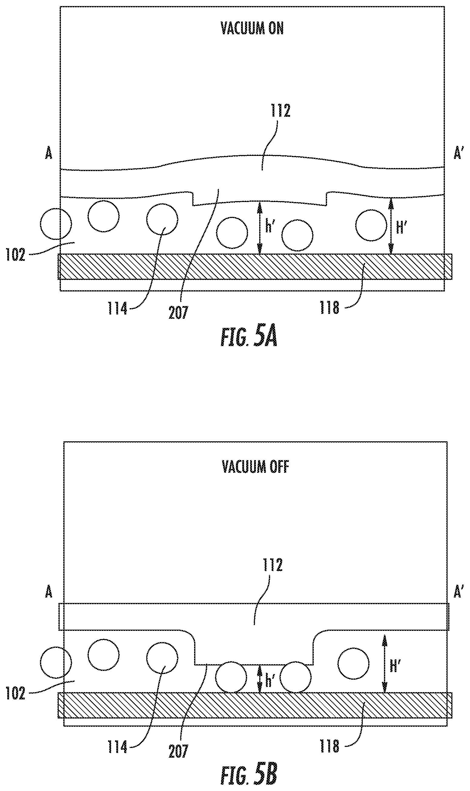
FIGS. 5A and 5B show cross-sectional views of an embodiment of the device for us with a vacuum source. (FIG. 5A) When vacuum is applied, the internal dimension (h') is greater than the diameter of the particles. (FIG. 5B) When vacuum is released, the particles are trapped by the deformable wall portion.
FIG. 6 is a graph showing the relationship between internal dimension of the microfluidic channel (channel height h') as a function of pneumatic pressure (P).
FIG. 7 shows a drawing of an embodiment of the device for analyzing 16 different particles with 4 different solution-switching functions.
FIG. 8 shows the particle trapping region in an embodiment of the device.
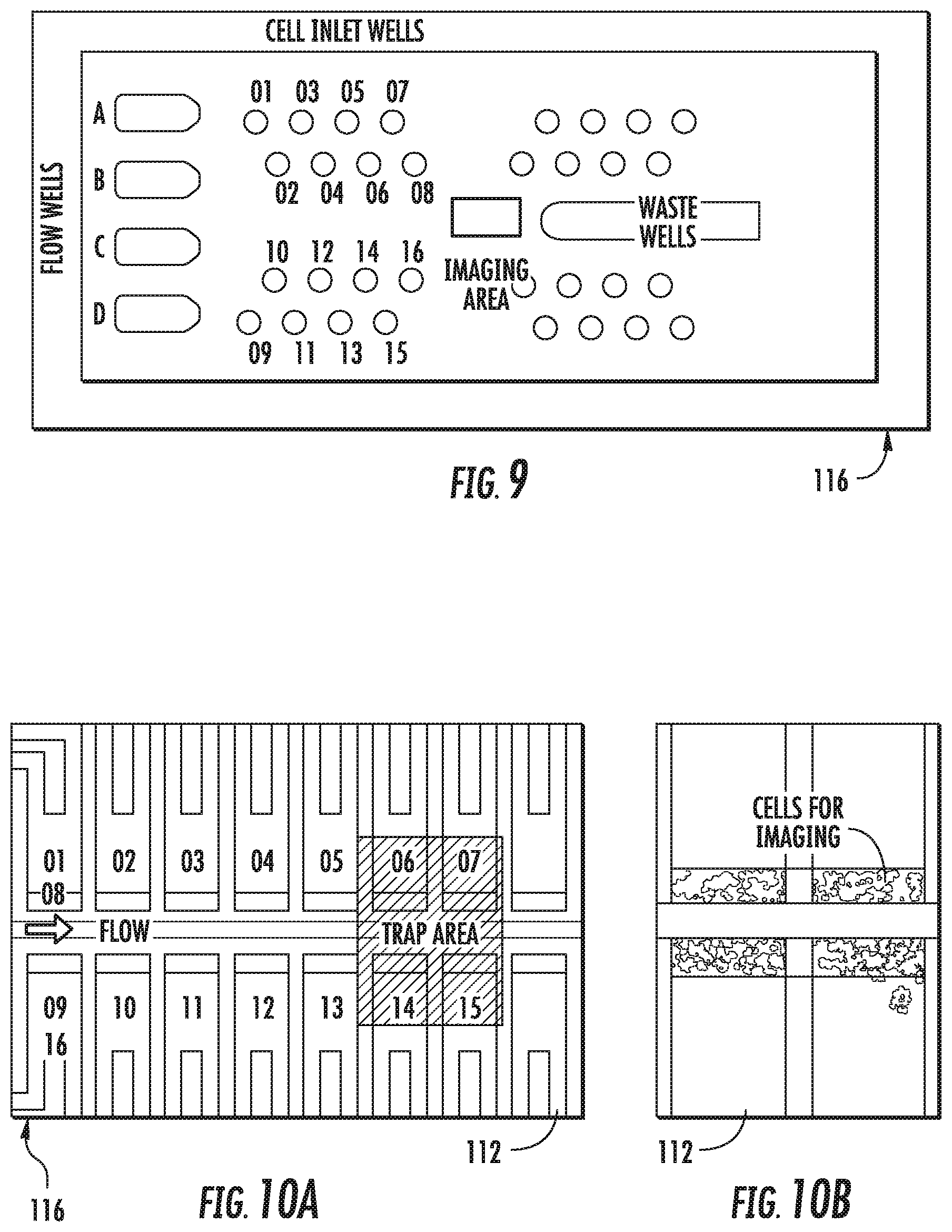
FIG. 9 shows an embodiment of the device for yeast cell imaging.
FIG. 10A shows an embodiment of the device for yeast cell imaging. FIG. 10B shows a picture of yeast cells trapped inside the channels the device shown in FIG. 10A.
FIG. 11 shows a schematic of an embodiment of the device for trapping beads as used for immunoassays.
FIG. 12 shows a cross-section of an embodiment of the device. The antibody-coated beads are concentrated inside the trapping region, and are subjected to a conventional assay protocol through reagent switching.
FIGS. 13A-13K illustrate steps in an exemplary fabrication method for making a microfluidic particle analysis device.
FIGS. 14A-14C show a control box and a manifold for use with the microfluidic particle analysis device.
DETAILED DESCRIPTION
A. Definitions
Prior to describing the present device and methods, the following terms and phrases are defined:
A "particle" refers to living or dead cells, such as mammalian, yeast, insect, and bacterial cells; beads such as polymer beads and metal beads; or other physical entities that may be trapped for analysis in accordance with the methods and device described, herein. Such particles have an average minimum diameter of between about 100 nm to about 50 .mu.m, preferably between about 1 .mu.m to about 30 .mu.m, more preferably between about 2 .mu.m to about 20 .mu.m, and even between about 3 .mu.m to about 10 .mu.m. Some particles can be coated or functionalized with additional layers of materials, e.g, gold-coated or antibody-coated polystyrene beads.
The "size" of a particle generally refers to its average or typical diameter. The device and methods are for use with substantially spherical particles or particles having a less than a 2-fold and even less than a 1.5-fold difference in the major and minor elliptical axis of non-spherical particles. The particles size generally excludes such extracellular structures as flagella, cilia, pilli, pseudopods, processes, or other readily deformable structures.
A "microchannel" or "microfluidic channel" refers to a micron-scale conduit for carrying fluid, solvents, solutes, and suspended micron-scale particles. A microchannel typically has a rectangular, e.g., square cross-section, with preferred width and depth dimensions of between about 10 .mu.m to about 500 .mu.m, and about 0.5 .mu.m to about 50 .mu.m, respectively. Micro-channels may also be elliptical or round. Fluids flowing in the microchannels may exhibit microfluidic behavior such as low Reynolds number and low turbulence. The microchannel channel has an internal dimension (referred to as a particle-flow dimension), defined by height H, which determines the maximum particle size that can enter the microchannel channel.
Where the microchannel includes a deformable wall portion, the deformable wall portion typically defines the particle-flow dimension, which is indicated as height h. This dimension is adjustable, using pneumatic pressure, from a relaxed condition, which prevents the passage of particles of a preselected size, to an expanded position, which allows the passage of these particles.
A "channel segment" is a particular structural or functional portion of a microchannel device, optionally in combination with one or more ports.
A "microfluidic body" refers to a device having various stations, wells, or reservoirs connected by micron-scale microchannels in which fluids will exhibit microfluidic behavior in their flow through the channels.
As used herein, "fluid contact" means arranged so as to allow fluid to flow from one vessel, chamber, or conduit to another, as described herein and as understood in the art. Fluid contact is synonymous with "fluid communication."
The terms "elastomer" and "elastomeric" should be given their standard meaning as used in the art. Allcock et al. (Contemporary Polymer Chemistry, 2nd Ed.) describes elastomers as polymers existing at a temperature between their glass transition temperature and liquefaction temperature. Elastomers generally deform under force and return to their original shape when the force is removed. The elasticity exhibited by elastomeric materials can be characterized by a Young's modulus. Elastomers for use with the microfluidic particle trapping device include but are not limited to polydimethylsiloxane (PDMS), polyisoprene, polybutadiene, polychloroprene, polyisobutylene, poly(styrene-butadiene-styrene), and members of the polyurethane and silicone families. Additional examples are provided in U.S. Pat. No. 7,144,616, which is incorporated herein by reference in its entirety for all purposes.
As used herein, "deformable" means readily changing shape or dimensions in response to stress or strain. Stress or strain includes fluid and pneumatic pressure. Upon the application of stress, deformable structures change shape from a relaxed condition to an expanded, compressed, bent, twisted, or distorted condition.
As used herein, "trapping" or "capturing" are used interchangeably to mean substantially immobilizing or confining between two elastomeric layers and/or between an elastic layer and an inelastic layer. A particle trapping region is synonymous with a particle capture region.
"Substantial fluid exchange" means replacement of fluid by ingress of a different fluid, as in washing particles immobilized in a column. Fluid exchange is substantial when at least 90%, and preferably at least 95% of fluid is replaced.
As used herein, a "port" is a point of ingress or egress for fluids and or gas. Fluids and gases may be provided to a port under pressure (including both positive and negative pressure), and may be delivered to a location within a microfluidic particle trapping device via microchannels.
As used herein, "pneumatic pressure" means pressure originating from air pressure, although air (or an inert or non-interfering gas) and/or fluid may contact the port of the device. Preferred pneumatic pressures are from about 0.1 pound per square inch (psi) to about 10 psi, from about 0.5 psi to about 7 psi, and from about 1 psi to about 5 psi. Exemplary pressures include, e.g., 1, 2, 3, 4, and 5 psi.
As used herein, "fluid pressure" means pressure exerted by a fluid, although the fluid pressure may be the result of pneumatic, hydraulic, gravitational, or capillary pressure. Preferred fluid pressures are from about 0.1 pound psi to about 10 psi, from about 0.5 psi to about 7 psi, and from about 1 psi to about 5 psi. Exemplary pressures include, e.g., 1, 2, 3, 4, and 5 psi.
The "substrate" is the base of the device, and may be transparent, at least under the trapping regions, to allow their visualization by microscopy or other optical methods. Alternatively, the substrate may include a light filtering or contrast-enhancing agent to assist in the assay. Examples of suitable substrates are glass (exemplified herein) and polycarbonate. Many other materials are suitable, depending on the application, and soft lithographic bonding on a substrate is known in the art (see, e.g., U.S. Pat. No. 7,144,616, which is incorporated herein by reference in its entirety for all purposes).
As used herein, the "height (h, h'. h''', etc.)" of the microfluidic channel trapping/capturing region is the particle-flow dimension corresponding to the distance separating the inside surface of the deformable wall portion from the opposite wall of the microfluidic channel. This internal dimension determines the diameter of the particles that can be trapped by the device
As used herein, "height H" of a microfluidic channel is the particle-flow dimension. Microfluidic channels having deformable wall portions have a "height h", which is the particle flow-dimension defined by the deformable wall portions. "H" and "h" are sometimes used to indicate the h has changed with respect to another drawing.
B. Particle Trapping Mechanisms
The device and method are best described with reference to the accompanying Figures. Common features are generally assigned the same numbers.
FIGS. 1A-C show a top (A) and side (B and C) views of simple embodiment of the microfluidic particle trapping device. A microfluidic body 86 has an inlet port 80 and outlet port 85 in fluid contact with a microfluidic channel. The microchannel has a particle trapping region 82 with a deformable wall portion 83, in fluid contact with secondary microchannel segments, e.g., 84, which are in contact with the ports 80 and 85. The secondary channel segments may be relatively nondeformable as suggested by the use of heavier lines.
FIG. 1D shows a top view of an embodiment of the microfluidic particle trapping device for particle analysis. The microfluidic body 116 is bonded to a substrate 118, such as a glass or plastic. The particle inlet port 102, solution inlet port 104, and solution outlet port 106, are in fluid contact with a microfluidic channel having a particle trapping region 112, via secondary microchannels 108 and 110. The particle inlet port and solution inlet port in combination with the associated microchannels, are generally referred to as inlet channel segments. The solution outlet port 106, in combination with the associated microchannels, is generally referred to as an outlet channel segment. The ports are generally adapted for receiving pneumatic pressures. As used herein, the particle inlet port 102 is upstream of the particle trapping region 112, while the solution inlet port 104, and solution outlet port 106 are downstream. Note that the arrangement of the various ports is not critical in some embodiments. The terms "upstream" and "downstream" are used to describe flow characteristics in different embodiments.
FIGS. 2A-2C show cross-sectional views (A-A') of the microfluidic particle trapping device in different stages of operation. The deformable wall portion 207 of the particle trapping region 112 is preferably made of an elastomer, such as PDMS (polydimethylsiloxane), such that the deformable wall changes from a relaxed condition to an expanded position in response to fluid pressure (e.g., as provided by pneumatic pressure). As shown in FIG. 2A, an internal dimension (height "h") is defined by the position of the deformable wall portion 207 of the particle trapping region 112. The secondary microchannels (i.e., 108 and 110) are designed such that their height ("H") is larger than the particle diameter. Although the deformable wall portions are generally depicted as having thicker channel-wall sections than the adjacent microchannel, the deformable wall portions may have thicker or thinner walls than the adjacent microchannel.
In other embodiments, a deformable wall portions relaxed condition, at which particles of a selected size are prevented from entering the particle capture region, to a first expanded position at which particles of a selected size may enter the capture region, and from the.
As shown in FIG. 2B, when a first pneumatic pressure is applied to the inlet port 102, the fluid pressure in the microfluidic channel increases and h' defined by the deformable wall portion 207 of the particle trapping region 112 becomes greater than the diameter of the particles 114, allowing the particles to move freely within the trapping region 112. When the inlet port 102 is pressurized to a second pneumatic pressure, as depicted in FIG. 2C, the fluid pressure in the microfluidic channel decreases, the deformable wall portion 207 defines a height of less than the particle diameter. Particles 114 present within the trapping region 112 are trapped (i.e., captured) by being sandwiched between the deformable wall of the microfluidic channel 207 and the bottom surface (substrate) 118 of the microfluidic device. Since the deformable wall is typically biased toward trapping the particles, the second pneumatic pressure may be zero (i.e., the same as the pressure external to the device), in which case, applying a second pneumatic pressure means allowing the deformable wall to return to its relaxed state or condition.
In other embodiments, the deformable wall portion is first deformed from a relaxed condition, at which particles of a selected size are prevented from entering the particle capture region, to a first expanded position, in which particles of a selected size may enter the capture region, and from the first expanded position to a second expanded position, in which the particles become trapped within said capture region. Pressure to drive the deformable wall portion from the first expanded position to a second expanded position may be provided via the ports or applied to the external surface of the microfluidic channels (see infra).
The trapped particles may then be exposed to (i.e., addressed with) a solution from port 104, e.g., by pressurizing the port with sufficient pressure to cause the solution to flow through the trapping region 112 to contact the particles 114, but insufficient to deform the deformable wall portion, allowing the particles to move or escape. The trapped particles may also be address with multiple solutions, for example, in a series or a particular sequence.
In preferred embodiments, addressing the trapped particles with a solution causes the particles to be displaced by less than about 10% of the size of the particles. For example, a trapped particle of about 10 .mu.m diameter is displaced by only about 1 .mu.m.
FIGS. 3A and 3B illustrate a further embodiment of the microfluidic particle trapping device 116 having additional features, which may be used alone or in combination. First, the embodiment has an additional port 202 in fluid contact with the inlet port 102. Following the release of pressure and the trapping of particles in the trapping region, the additional port 202 allows particles outside the trapping region 112 to be flushed from the microfluidic particle trapping device by means of fluid flow from additional port 202 to inlet port 102 or from inlet port 102 to additional port 202. Depending on the direction of flow, the additional port 202 is considered part of the inlet channel segment or outlet channel segment.
Second, the embodiment shown in FIGS. 3A and 3B has a first and second trapping region 204 and 210, respectively, with independent deformable walls portion 208 and 209, respectively, or sharing a common deformable wall portion that defines different particle-flow dimensions. According to this embodiment, the microfluidic channel has dimensions h'' and h''', which are adjustable by pneumatic pressure for trapping particles having different diameters. The particle trapping device may have any number of longitudinally spaced trapping/capture regions, for example, 1, 2, 3, 4, 5, etc. In some embodiments, the particle-flow dimension decreases with each successive trapping segment, such that the particle-flow dimension of the trapping segment most proximal to the particle inlet 102 is greatest and that most distal to the particle inlet is least.
Third the embodiment shown in FIGS. 3A and 3B further incorporates a microfluidic mesh region 206 having a mesh size less than the diameter of the particles to prevent the particles leaving the trapping region 204 and 210 (i.e., flowing through the trapping region and out the solution inlet port 104 or outlet port 106. The microfluidic mesh region 206 is particularly useful when multiple solution inlet ports 104 are arrayed along a common solution-introduction channel 104. In such cases, the mesh region 206 prevents particles introduced to one particle inlet port from migrating through the adjacent trapping layer, and then exiting the device downstream of the trapping layer. The mesh region 206 is shown in contact with the substrate 118 but may be spaced apart so long as the particles do not escape. A trapping layer with a small particle flow dimension may also be used to prevent particles from leaving the trapping region.
FIGS. 4A and 4B show cross-sectional views of an embodiment of the microfluidic particle trapping device having a deformable wall portion with a cavity 211. At the first pneumatic pressure, with the deformable wall portion in the expanded condition, the internal dimension (h') is greater than the diameter of the particles 114, allowing the particles from the particle inlet port 102 to flow freely under the deformable wall portion. At the second pneumatic pressure, with the deformable wall portion in the relaxed condition, the particles are trapped between the deformable wall portion 211 and the substrate/base 118.
The previous embodiments of the device are described with reference to applying a positive pressure to the microfluidic channel via the ports, thereby increasing the pressure inside the channel relative to the pressure outside the channel, and causing the deformable wall portion to change shape. In another embodiment, the pressure in the microfluidic channel is increased, relative to the pressure outside the chamber, by exposing the outside surface of the microfluidic chamber, adjacent to the deformable wall portion, to a negative pressure, i.e., a vacuum. This may be accomplished by applying localized vacuum to a suitably adapted embodiment of the microfluidic device, or by placing the microfluidic body in a vacuum chamber, while the ports remain exposed to atmospheric pressure. This embodiment is shown in FIGS. 5A and 5B.
The deformable wall portion 207, trapping portion 112, substrate 118, are essentially as described. The format of the particle inlet port 102 is different. Surfaces exposed to vacuum are inside the box. Outside the box is atmospheric pressure (or at least less vacuum pressure than inside the box). When vacuum is applied, the internal dimension (h') is greater than the diameter of the particles 114. When vacuum is released, the particles 114 are trapped by the deformable wall portion 207.
FIG. 6 is a graph showing the relationship between the height (h) of the trapping region and the pneumatic pressure applied to the device. When a pneumatic pressure (x-axis) is applied, e.g., via the inlet port or solution port, the fluid pressure in the microfluidic channel changes and the deformable wall of the trapping region experiences height deformation (y-axis). Generally, the greater the positive pressure in the trapping region, the greater the height (h) of the trapping region. The critical pressure is the pressure at which the height of the trapping region is substantially equal to the diameter of the particle. When the applied pressure is greater than the critical pressure, the particles can move freely within or through the trapping region. When the applied pressure is less than the critical pressure, the particles within the trapping region are trapped. One skilled in the art will recognize that there are numerous ways to produce the small pressure differential required for deforming a deformable wall.
C. Yeast Cell Imaging Device
FIG. 7 is a schematic diagram of another embodiment of the microfluidic particle trapping device. The trapping regions are placed close to each other for the convenience of microscopic analysis. The device provides up to four solution-switching stations (e.g., solution inlet ports 104, A-D) for analyzing the trapped particles. FIG. 7 shows a more detailed view of the particle trapping regions 112. In this example, there are 16 particle trapping regions 112 inside the single field of view of a 10.times. objective. A particle inlet port 102, solution inlet port 104, and solution outlet port 106 are indicated.
FIG. 9 shows an image of an actual fabricated embodiment of the device for yeast cell imaging. The device is similar to that shown in the schematic in FIG. 7. This particular embodiment of the device is 24 mm in width and 60 mm in length, with microchannels of 30 .mu.m in height, and two trapping regions having internal dimensions of 8 .mu.m and 3 .mu.m, respectively. In this example, there are 16 yeast cell trapping regions arrayed along a common flow channel.
FIG. 10A shows a detailed view of the imaging area indicated in FIG. 9. The imaging area includes the trapping regions with deformable wall portions. FIG. 10B shows an image of yeast trapped in the trap area indicated in FIG. 10A. Up to 4 trapping regions are visible under a single field of a 20.times. objective microscope lens. Yeast cells for use with this embodiment have an average size of 5 .mu.m; therefore, the yeast cells are trapped only in the 3 .mu.m trapping region. The device is capable of trapping yeast from up to 16 different particle preparations (for example, 16 yeast strains, each with a different genetic modification), and introducing up to 4 different reagents, e.g., for yeast gene expression study.
D. Microfluidic Bead-Based Immunoassay
In related embodiments, the microfluidic particle trapping body 116 is adapted for "lab-on-a-chip" diagnosis. FIG. 11 shows a schematic design of a microfluidic bead-based immunoassay chip embodiment of the device. The exemplary assay uses the "sandwich" immunoassay method. Different biomarkers (e.g., antibodies for different disease-associated antigens) can be immobilized on beads and introduced into the trapping regions 112, which are similar to those depicted in FIGS. 10A and 10B. A microfluidic mesh region 206, or an additional trapping layer having an insufficient height to allow the passage of the particles 204, may optionally be used to prevent the beads from one trapping region from crossing into other trapping regions.
After the beads are trapped (as shown in FIG. 12), a solution or suspension, such as a patient's serum, is introduced into the trapping regions 112 from an inlet port 104 at a pressure insufficient to raise the height of the trapping region, thereby exposing the trapped beads coated with different antibodies to the serum without releasing the beads from the trapping region. Matching antigens present in the serum bind to the antibody coated beads. After washing out the serum (e.g., with a saline solution, such as PBS), an antibody mixture with specificity to the desired antigens is introduced to label the bound antigens. A secondary antibody and fluorescent substrate is typically then introduced, and the calorimetric, fluorescent, radioactive, or other signal can be analyzed using standard detection methods, where the signal from each microchamber is correlated to a specific antigen, such as a biomarker.
A key feature of this immunoassay that distinguishes it from other chip-based diagnostic assays is that the trapping region acts like a "concentrator" by packing the beads into a single layer. In this manner, particles present in three-dimensional space (i.e., in a fluid volume) are concentrated into essentially two-dimensions, because the third dimension is approximately the same height as the trapped particles. Concentrating the particles greatly increased the signal-to-noise ratio compared to conventional assays.
E. Microfabrication Methods
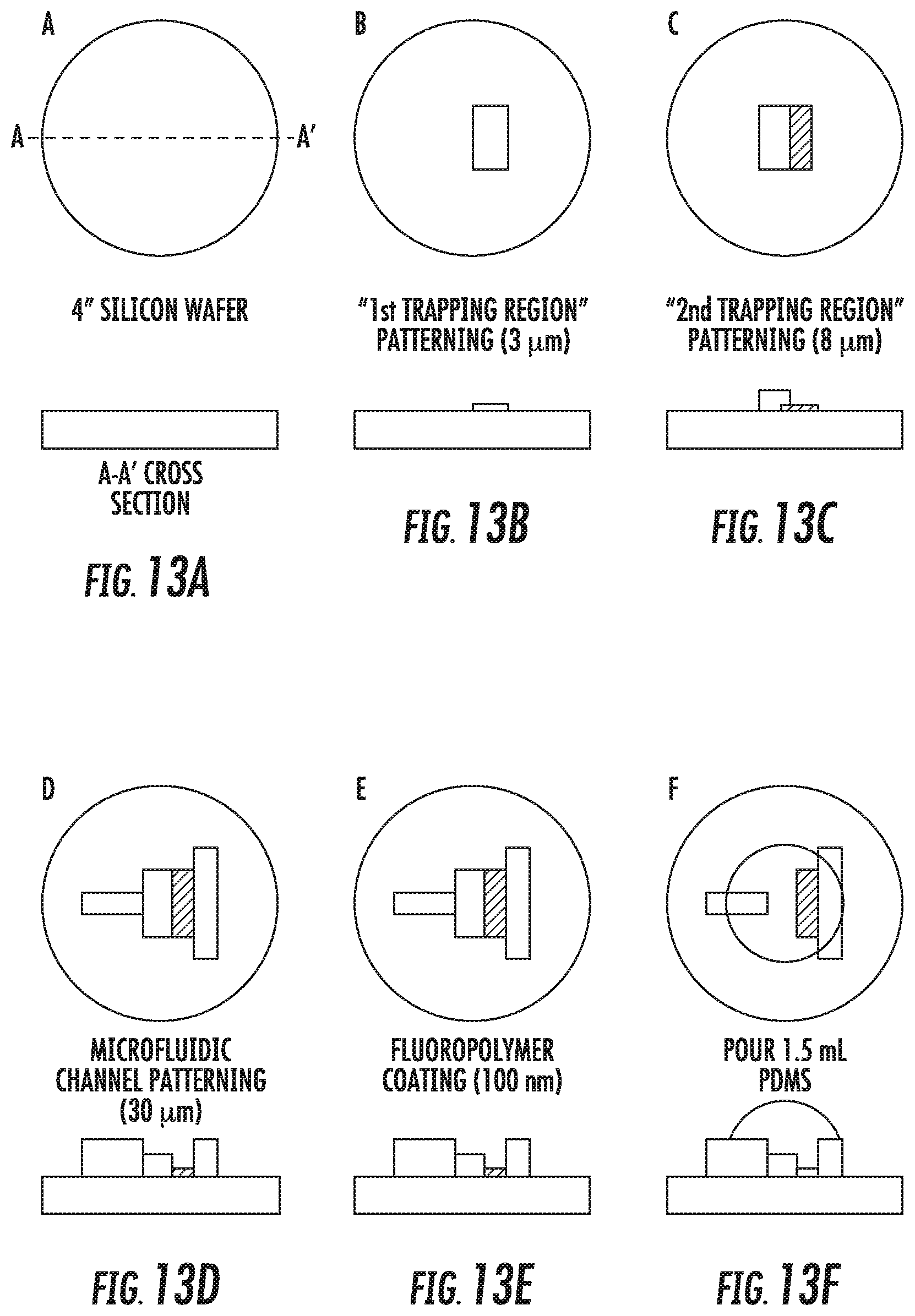
FIGS. 13A-13K show an exemplary method for manufacturing a microfluidic particle trapping device. The various steps are labeled A-K. The process starts with a blank, 4'' test-grade silicon wafer (A). A negative photoresist (SU8 2002 Microchem) is spin coated at a final thickness of 3 .mu.m and the first trapping region is patterned through standard photolithography (B). A second layer of negative photoresist (SU8 2005 Microchem) is spin coated at a final thickness of 8 .mu.m and the second trapping region is patterned through standard photolithography (C). A third layer of negative photoresist (SU8 2025 Microchem) is spin coated at a final thickness of 30 .mu.m and the rest of the microfluidic structures are patterned through standard photolithography (D). The mold is then coated with a 100 nm thick fluoropolymer using C.sub.4F.sub.8 plasma (1 torr, 300 W, 3 minutes, Surface Technology System) to create an extremely hydrophobic surface (contact angle .about.140.degree. C.) to increase mold durability and prevent PDMS stiction (E).
The molding process starts with pouring 1.5 mL PDMS (Sylgard 184, Dow Corning, 10-parts monomer mixed with 1-part curing agent) on the 4'' fluoropolymer-coated silicon mold (F). The PDMS is degassed in a vacuum chamber (26'' Hg for 30 minutes to remove bubbles generated during the mixing). A 3 mm thick PMMA sheet is spin coated with a primer (Sylgard PrimeCoat, Dow Corning) and pressed onto the mold (G). The mold is placed in a 60.degree. C. oven for 2 hours to allow the PDMS to cure. After removing the mold from the oven, the PMMA sheet is detached from the silicon mold (H). Because the surface of the PMMA sheet is modified by the primer, the cured PDMS adheres to the PMMA sheet and is detached from the silicon mold with the PMMA sheet. Fluidic reservoirs are cut by a CO.sub.2 laser writer (VersaLaser, 25W) (I). The laser writer is equipped with precise step motors; therefore, the reservoirs can be cut at specific locations with high accuracy. The mold replicate is then bonded to a #1 coverglass (J) after oxygen plasma treatment (200 mtorr, 10 W, 15 seconds, TechnicsLab) to render the PDMS surface hydroxyl group rich. The device is then primed with distilled deionized water and sealed with gas impermeable tape to avoid evaporation before use (K).
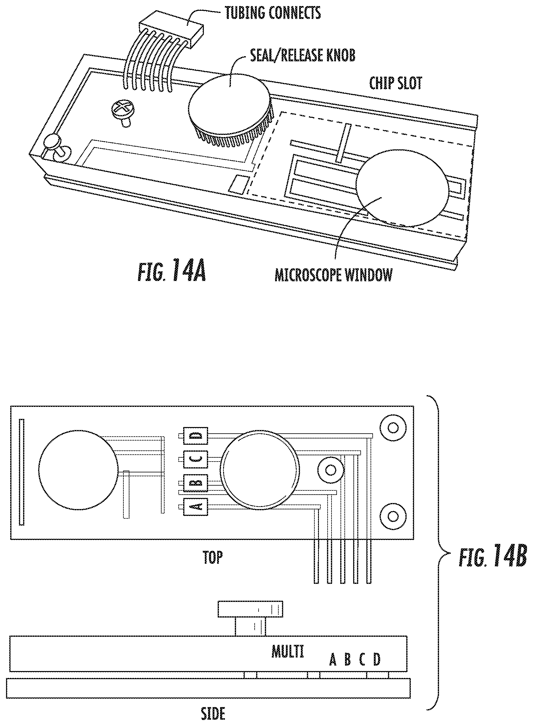
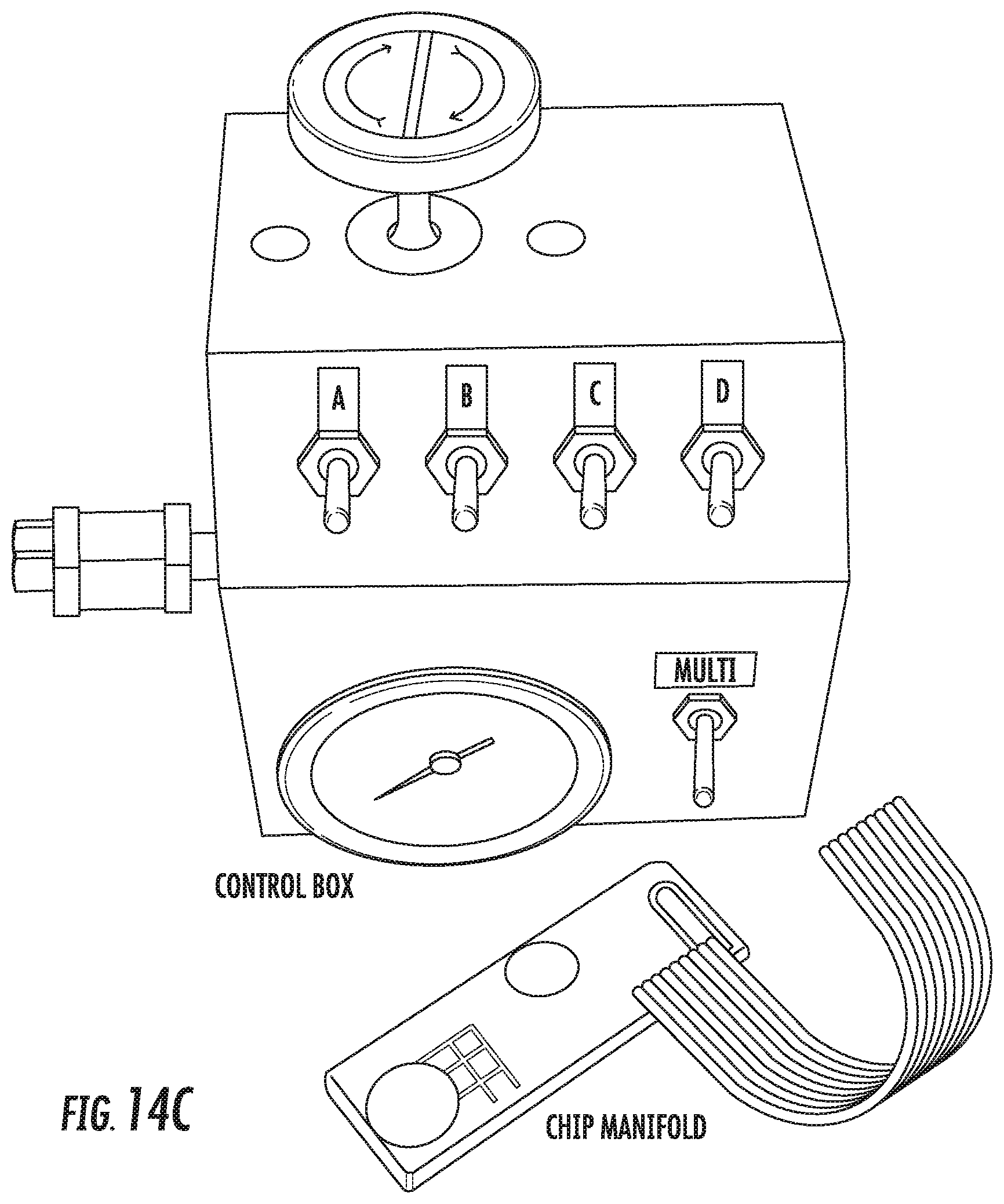
Exemplary embodiments of the device are shown in FIGS. 14A and 14B. The device may be connected to a manifold of a control box (or pressure regulator) for applying pneumatic pressure, such as the unit shown in FIG. 14. The device slides into the manifold, where a silicone gasket with openings aligns with the reservoirs of the device. The center (seal/release) knob is hand tightened so the silicone gasket and the device form a seal. An imaging window is cut from the bottom of the manifold to enable microscopy. The control box can be connected to a laboratory air pressure line, air compressor pump, or other suitable source of air pressure. The control box is equipped with a precision pressure regulator (0 to 5 psi) to control the flow rate and the amount of deformation of the trapping regions.
The above description and illustrations are provided only to exemplify the methods and the device for particle analysis. Addition aspects and embodiments will be apparent to the skilled artisan without departing from the scope of the invention.
* * * * *
D00000
D00001
D00002
D00003
D00004
D00005
D00006
D00007
D00008
D00009
D00010
D00011
D00012

D00013
D00014
XML
uspto.report is an independent third-party trademark research tool that is not affiliated, endorsed, or sponsored by the United States Patent and Trademark Office (USPTO) or any other governmental organization. The information provided by uspto.report is based on publicly available data at the time of writing and is intended for informational purposes only.
While we strive to provide accurate and up-to-date information, we do not guarantee the accuracy, completeness, reliability, or suitability of the information displayed on this site. The use of this site is at your own risk. Any reliance you place on such information is therefore strictly at your own risk.
All official trademark data, including owner information, should be verified by visiting the official USPTO website at www.uspto.gov. This site is not intended to replace professional legal advice and should not be used as a substitute for consulting with a legal professional who is knowledgeable about trademark law.