Expandable implant
Alheidt , et al. January 26, 2
U.S. patent number 10,898,344 [Application Number 15/959,716] was granted by the patent office on 2021-01-26 for expandable implant. This patent grant is currently assigned to Stryker European Operations Holdings LLC. The grantee listed for this patent is Stryker European Operations Holdings LLC. Invention is credited to Thomas A. Alheidt, Dan Boljonis, Julien Doreau, Christine Herrmann, Bryan D. Milz.


View All Diagrams
| United States Patent | 10,898,344 |
| Alheidt , et al. | January 26, 2021 |
Expandable implant
Abstract
An expandable implant is disclosed in which the implant includes top and bottom plates having angled inner surfaces that interact with expansion members. The expansion members may be situated on an actuator, and may include at least one vertical projection. In some instances, rotation of the actuator in opposing directions about a longitudinal axis may cause the expansion members to move toward or away from one another, thereby resulting in separation of the top and bottom plates. During such expansion of the implant, the at least one vertical projection of the expansion members may be guided at least partially within a recess formed in the first or second plate. Pins may also be included with the expansion members that ride along respective slots in the plates during expansion. An insertion instrument for implanting the aforementioned implant, and methods of using the same, are also disclosed.
| Inventors: | Alheidt; Thomas A. (Sussex, NJ), Milz; Bryan D. (Florida, NY), Boljonis; Dan (Middletown, NJ), Doreau; Julien (Illats, FR), Herrmann; Christine (Fair Lawn, NJ) | ||||||||||
|---|---|---|---|---|---|---|---|---|---|---|---|
| Applicant: |
|
||||||||||
| Assignee: | Stryker European Operations
Holdings LLC (Wilmington, DE) |
||||||||||
| Appl. No.: | 15/959,716 | ||||||||||
| Filed: | April 23, 2018 |
Prior Publication Data
| Document Identifier | Publication Date | |
|---|---|---|
| US 20180303625 A1 | Oct 25, 2018 | |
Related U.S. Patent Documents
| Application Number | Filing Date | Patent Number | Issue Date | ||
|---|---|---|---|---|---|
| 15091058 | May 8, 2018 | 9962270 | |||
| 13587205 | Apr 26, 2016 | 9320610 | |||
| 61523981 | Aug 16, 2011 | ||||
| Current U.S. Class: | 1/1 |
| Current CPC Class: | A61F 2/442 (20130101); A61F 2/447 (20130101); A61F 2/4611 (20130101); A61F 2002/30843 (20130101); A61F 2002/30904 (20130101); A61F 2002/30281 (20130101); A61F 2002/30892 (20130101); A61F 2/4603 (20130101); A61F 2002/30556 (20130101); A61F 2002/30827 (20130101); A61F 2002/30785 (20130101); A61F 2002/30507 (20130101); A61F 2002/30397 (20130101); A61F 2002/30601 (20130101); A61F 2002/4628 (20130101); A61F 2002/30777 (20130101); A61F 2002/4627 (20130101); A61F 2002/30622 (20130101); A61F 2002/30878 (20130101); A61F 2002/3055 (20130101); A61F 2002/30594 (20130101); A61F 2002/30405 (20130101); A61F 2002/30523 (20130101); A61F 2002/30433 (20130101); A61F 2002/3039 (20130101); A61F 2002/304 (20130101); A61F 2002/30579 (20130101); A61F 2002/30607 (20130101) |
| Current International Class: | A61F 2/44 (20060101); A61F 2/46 (20060101); A61F 2/30 (20060101) |
References Cited [Referenced By]
U.S. Patent Documents
| 2799196 | July 1957 | Alvarez |
| 3426364 | February 1969 | Lumb |
| 3486505 | December 1969 | Morrison |
| 4309777 | January 1982 | Patil |
| 4401112 | August 1983 | Rezaian |
| 4522200 | June 1985 | Stednitz |
| 4545374 | October 1985 | Jacobson |
| 4553273 | November 1985 | Wu |
| 4599086 | July 1986 | Doty |
| 4636217 | January 1987 | Ogilvie et al. |
| 4657550 | April 1987 | Daher |
| 4733665 | March 1988 | Palmaz |
| 4863476 | September 1989 | Shepperd |
| 4878915 | November 1989 | Brantigan |
| 4932375 | June 1990 | Burney |
| 4932969 | June 1990 | Frey et al. |
| 4936851 | June 1990 | Fox et al. |
| 4946378 | August 1990 | Hirayama et al. |
| 5059193 | October 1991 | Kuslich |
| 5171278 | December 1992 | Pisharodi |
| 5192327 | March 1993 | Brantigan |
| 5236460 | August 1993 | Barber |
| 5344252 | September 1994 | Kakimoto |
| 5390683 | February 1995 | Pisharodi |
| 5425772 | June 1995 | Brantigan |
| 5484437 | January 1996 | Michelson |
| 5522899 | June 1996 | Michelson |
| 5554191 | September 1996 | Lahille et al. |
| 5562736 | October 1996 | Ray et al. |
| 5571190 | November 1996 | Ulrich et al. |
| 5571192 | November 1996 | Schonhoffer |
| 5593409 | January 1997 | Michelson |
| 5609635 | March 1997 | Michelson |
| 5653762 | August 1997 | Pisharodi |
| 5653763 | August 1997 | Errico et al. |
| 5658335 | August 1997 | Allen |
| 5665122 | September 1997 | Kambin |
| 5693100 | December 1997 | Pisharodi |
| 5702453 | December 1997 | Rabbe et al. |
| 5772661 | June 1998 | Michelson |
| 5776197 | July 1998 | Rabbe et al. |
| 5776199 | July 1998 | Michelson |
| 5782832 | July 1998 | Larsen et al. |
| 5865848 | February 1999 | Baker |
| 5888228 | March 1999 | Knothe et al. |
| 5893889 | April 1999 | Harrington |
| 5893890 | April 1999 | Pisharodi |
| 5972015 | October 1999 | Scribner et al. |
| 5980522 | November 1999 | Koros et al. |
| 6015436 | January 2000 | Schonhoffer |
| 6039761 | March 2000 | Li et al. |
| 6045579 | April 2000 | Hochshuler et al. |
| 6080155 | June 2000 | Michelson |
| 6080193 | June 2000 | Hochshuler et al. |
| 6083225 | July 2000 | Winslow et al. |
| 6083228 | July 2000 | Michelson |
| 6090143 | July 2000 | Meriwether et al. |
| 6093207 | July 2000 | Pisharodi |
| 6102949 | August 2000 | Biedermann et al. |
| 6102950 | August 2000 | Vaccaro |
| 6113638 | September 2000 | Williams et al. |
| 6117174 | September 2000 | Nolan |
| 6127597 | October 2000 | Beyar et al. |
| 6156037 | December 2000 | LeHuec et al. |
| 6159244 | December 2000 | Suddaby |
| 6159245 | December 2000 | Meriwether et al. |
| 6174334 | January 2001 | Suddaby |
| 6176882 | January 2001 | Biedermann et al. |
| 6183517 | February 2001 | Suddaby |
| 6190414 | February 2001 | Young et al. |
| 6193756 | February 2001 | Studer et al. |
| 6193757 | February 2001 | Foley et al. |
| 6206923 | March 2001 | Boyd et al. |
| 6210412 | April 2001 | Michelson |
| 6217579 | April 2001 | Koros |
| 6224604 | May 2001 | Suddaby |
| 6245107 | June 2001 | Ferree |
| 6280456 | August 2001 | Scribner et al. |
| 6287308 | September 2001 | Betz et al. |
| 6302914 | October 2001 | Michelson |
| 6328738 | December 2001 | Suddaby |
| 6332895 | December 2001 | Suddaby |
| 6344057 | February 2002 | Rabbe et al. |
| 6368351 | April 2002 | Glenn et al. |
| 6395031 | May 2002 | Foley et al. |
| 6395032 | May 2002 | Gauchet |
| 6395034 | May 2002 | Suddaby |
| 6402750 | June 2002 | Atkinson et al. |
| 6409766 | June 2002 | Brett |
| 6432140 | August 2002 | Lin |
| 6436103 | August 2002 | Suddaby |
| 6436140 | August 2002 | Liu et al. |
| 6443989 | September 2002 | Jackson |
| 6443990 | September 2002 | Aebi et al. |
| 6447544 | September 2002 | Michelson |
| 6447547 | September 2002 | Michelson |
| 6451052 | September 2002 | Burmeister et al. |
| 6454806 | September 2002 | Cohen et al. |
| 6454807 | September 2002 | Jackson |
| 6478823 | November 2002 | Michelson |
| 6491724 | December 2002 | Ferree |
| 6527803 | March 2003 | Crozet et al. |
| D472632 | April 2003 | Anderson |
| D472633 | April 2003 | Anderson |
| 6562074 | May 2003 | Gerbec et al. |
| 6576016 | June 2003 | Hochshuler et al. |
| 6582431 | June 2003 | Ray |
| 6582451 | June 2003 | Marucci et al. |
| 6582461 | June 2003 | Burmeister et al. |
| 6582467 | June 2003 | Teitelbaum et al. |
| 6592625 | July 2003 | Cauthen |
| 6595998 | July 2003 | Johnson et al. |
| 6610089 | August 2003 | Liu et al. |
| 6626905 | September 2003 | Schmiel et al. |
| 6641614 | November 2003 | Wagner et al. |
| 6648917 | November 2003 | Gerbec et al. |
| 6666891 | December 2003 | Boehm, Jr. et al. |
| 6679915 | January 2004 | Cauthen |
| 6685742 | February 2004 | Jackson |
| 6706070 | March 2004 | Wagner |
| 6719796 | April 2004 | Cohen et al. |
| 6723126 | April 2004 | Berry |
| 6733535 | May 2004 | Michelson |
| 6743255 | June 2004 | Ferree |
| 6758849 | July 2004 | Michelson |
| 6773460 | August 2004 | Jackson |
| 6814754 | November 2004 | Greenhalgh |
| 6814756 | November 2004 | Michelson |
| 6821298 | November 2004 | Jackson |
| 6833006 | December 2004 | Foley et al. |
| 6835206 | December 2004 | Jackson |
| 6837850 | January 2005 | Suddaby |
| 6840944 | January 2005 | Suddaby |
| 6843804 | January 2005 | Bryan |
| 6852129 | February 2005 | Gerbec et al. |
| 6863673 | March 2005 | Gerbec et al. |
| 6875173 | April 2005 | Suddaby |
| 6893464 | May 2005 | Kiester |
| 6902568 | June 2005 | Serhan |
| 6923810 | August 2005 | Michelson |
| 6953477 | October 2005 | Berry |
| 6955691 | October 2005 | Chae et al. |
| 6962606 | November 2005 | Michelson |
| 7018415 | March 2006 | McKay |
| 7066961 | June 2006 | Michelson |
| 7070598 | July 2006 | Lim et al. |
| 7083650 | August 2006 | Moskowitz et al. |
| 7087055 | August 2006 | Lim et al. |
| 7094257 | August 2006 | Mujwid et al. |
| 7097648 | August 2006 | Globerman et al. |
| 7128760 | October 2006 | Michelson |
| 7204853 | April 2007 | Gordon et al. |
| 7214243 | May 2007 | Taylor |
| 7217291 | May 2007 | Zucherman et al. |
| 7220280 | May 2007 | Kast et al. |
| D553742 | October 2007 | Park |
| 7282063 | October 2007 | Cohen et al. |
| 7306626 | December 2007 | Whelan |
| 7311733 | December 2007 | Metz-Stavenhagen |
| 7316714 | January 2008 | Gordon et al. |
| 7326250 | February 2008 | Beaurain et al. |
| 7326251 | February 2008 | McCombe et al. |
| 7331996 | February 2008 | Sato et al. |
| 7503933 | March 2009 | Michelson |
| 7569074 | August 2009 | Eisermann et al. |
| 7618456 | November 2009 | Mathieu et al. |
| 7618458 | November 2009 | Biedermann et al. |
| 7621951 | November 2009 | Glenn et al. |
| 7655042 | February 2010 | Foley et al. |
| 7674297 | March 2010 | Falahee |
| 7678148 | March 2010 | Peterman |
| 7708778 | May 2010 | Gordon et al. |
| 7708779 | May 2010 | Edie et al. |
| 7727280 | June 2010 | McLuen |
| 7731751 | June 2010 | Butler et al. |
| 7731752 | June 2010 | Edie et al. |
| 7753958 | July 2010 | Gordon et al. |
| 7780732 | August 2010 | Abernathie |
| 7789914 | September 2010 | Michelson |
| 7794501 | September 2010 | Edie et al. |
| 7824445 | November 2010 | Biro et al. |
| 7837734 | November 2010 | Zucherman et al. |
| 7850733 | December 2010 | Baynham et al. |
| 7909830 | March 2011 | Frigg et al. |
| 7909869 | March 2011 | Gordon et al. |
| 7985256 | July 2011 | Grotz et al. |
| 8021430 | September 2011 | Michelson |
| 8062375 | November 2011 | Glerum et al. |
| 8070813 | December 2011 | Grotz et al. |
| 8096994 | January 2012 | Phan et al. |
| 8105358 | January 2012 | Phan |
| 8105382 | January 2012 | Olmos et al. |
| 8118870 | February 2012 | Gordon et al. |
| 8118871 | February 2012 | Gordon et al. |
| 8123810 | February 2012 | Gordon et al. |
| 8147550 | April 2012 | Gordon et al. |
| 8172903 | May 2012 | Gordon et al. |
| 8187331 | May 2012 | Strohkirch, Jr. et al. |
| D664252 | July 2012 | Weiland et al. |
| 8257440 | September 2012 | Gordon et al. |
| 8267939 | September 2012 | Cipoletti et al. |
| 8273124 | September 2012 | Renganath et al. |
| 8273126 | September 2012 | Lindner |
| 8303662 | November 2012 | Landry et al. |
| 8303663 | November 2012 | Jimenez et al. |
| 8328818 | December 2012 | Seifert et al. |
| 8337558 | December 2012 | Lindner |
| 8366777 | February 2013 | Matthis et al. |
| 8394143 | March 2013 | Grotz et al. |
| 8435296 | May 2013 | Kadaba et al. |
| 8454695 | June 2013 | Grotz et al. |
| 8480741 | July 2013 | Grotz et al. |
| 8568481 | October 2013 | Olmos et al. |
| 9962270 | May 2018 | Alheidt |
| 2001/0032020 | October 2001 | Besselink |
| 2002/0045945 | April 2002 | Liu et al. |
| 2002/0052656 | May 2002 | Michelson |
| 2002/0068974 | June 2002 | Kuslich et al. |
| 2002/0068977 | June 2002 | Jackson |
| 2002/0082696 | June 2002 | Harms et al. |
| 2002/0128716 | September 2002 | Cohen et al. |
| 2002/0138146 | September 2002 | Jackson |
| 2003/0004575 | January 2003 | Erickson |
| 2003/0040798 | February 2003 | Michelson |
| 2003/0065396 | April 2003 | Michelson |
| 2003/0135279 | July 2003 | Michelson |
| 2003/0149482 | August 2003 | Michelson |
| 2003/0171813 | September 2003 | Kiester |
| 2003/0195630 | October 2003 | Ferree |
| 2003/0208263 | November 2003 | Burmeister et al. |
| 2003/0208270 | November 2003 | Michelson |
| 2003/0208272 | November 2003 | Crozet et al. |
| 2003/0208275 | November 2003 | Michelson |
| 2003/0220650 | November 2003 | Major et al. |
| 2003/0236520 | December 2003 | Lim et al. |
| 2004/0010312 | January 2004 | Enayati |
| 2004/0010315 | January 2004 | Song |
| 2004/0024460 | February 2004 | Ferree |
| 2004/0024463 | February 2004 | Thomas, et al. |
| 2004/0030387 | February 2004 | Landry et al. |
| 2004/0044411 | March 2004 | Suddaby |
| 2004/0078080 | April 2004 | Thramann et al. |
| 2004/0087947 | May 2004 | Lim et al. |
| 2004/0087948 | May 2004 | Suddaby |
| 2004/0102774 | May 2004 | Trieu |
| 2004/0153156 | August 2004 | Cohen et al. |
| 2004/0199252 | October 2004 | Sears et al. |
| 2004/0215342 | October 2004 | Suddaby |
| 2004/0225360 | November 2004 | Malone |
| 2004/0243240 | December 2004 | Beaurain et al. |
| 2004/0254643 | December 2004 | Jackson |
| 2004/0254644 | December 2004 | Taylor |
| 2005/0004673 | January 2005 | Kluger |
| 2005/0015149 | January 2005 | Michelson |
| 2005/0015150 | January 2005 | Lee |
| 2005/0027358 | February 2005 | Suddaby |
| 2005/0038512 | February 2005 | Michelson |
| 2005/0049590 | March 2005 | Alleyne et al. |
| 2005/0060036 | March 2005 | Schultz et al. |
| 2005/0070911 | March 2005 | Carrison et al. |
| 2005/0071007 | March 2005 | Malek |
| 2005/0113920 | May 2005 | Foley et al. |
| 2005/0273171 | December 2005 | Gordon et al. |
| 2005/0278026 | December 2005 | Gordon et al. |
| 2006/0022180 | February 2006 | Selness |
| 2006/0064169 | March 2006 | Ferree |
| 2006/0116767 | June 2006 | Magerl et al. |
| 2006/0122701 | June 2006 | Kiester |
| 2006/0129244 | June 2006 | Ensign |
| 2006/0149385 | July 2006 | McKay |
| 2006/0206207 | September 2006 | Dryer et al. |
| 2006/0224241 | October 2006 | Butler et al. |
| 2006/0241643 | October 2006 | Lim et al. |
| 2006/0241764 | October 2006 | Michelson |
| 2006/0247770 | November 2006 | Peterman |
| 2006/0253201 | November 2006 | McLuen |
| 2008/0058931 | March 2008 | White et al. |
| 2008/0071279 | March 2008 | Bandeira et al. |
| 2008/0082173 | April 2008 | Delurio et al. |
| 2008/0140207 | June 2008 | Olmos |
| 2009/0222100 | September 2009 | Cipoletti et al. |
| 2010/0017965 | January 2010 | Barthelt |
| 2010/0049325 | February 2010 | Biedermann et al. |
| 2010/0145455 | June 2010 | Simpson et al. |
| 2010/0211176 | August 2010 | Greenhalgh |
| 2010/0280616 | November 2010 | Frasier |
| 2010/0286779 | November 2010 | Thibodeau |
| 2010/0286780 | November 2010 | Dryer et al. |
| 2010/0292796 | November 2010 | Greenhalgh et al. |
| 2010/0331985 | December 2010 | Gordon et al. |
| 2011/0130838 | June 2011 | Morgenstern Lopez |
| 2011/0160861 | June 2011 | Jimenez |
| 2011/0172774 | July 2011 | Varela |
| 2012/0035729 | February 2012 | Glerum et al. |
| 2012/0071982 | March 2012 | Michelson |
| 2012/0191194 | July 2012 | Olmos et al. |
| 2012/0290094 | November 2012 | Lim et al. |
| 2012/0310349 | December 2012 | Gordon et al. |
| 2012/0316652 | December 2012 | Renganath et al. |
| 1333209 | Nov 1994 | CA | |||
| 3729600 | Mar 1989 | DE | |||
| 102005022920 | Nov 2006 | DE | |||
| 0260044 | Mar 1988 | EP | |||
| 0269175 | Jun 1988 | EP | |||
| 0566807 | Oct 1993 | EP | |||
| 0637439 | Feb 1995 | EP | |||
| 0664994 | Aug 1995 | EP | |||
| 0669114 | Aug 1995 | EP | |||
| 0734702 | Oct 1996 | EP | |||
| 1293180 | Mar 2003 | EP | |||
| 2083754 | Mar 1982 | GB | |||
| 2219060 | Nov 1989 | GB | |||
| 62164458 | Jul 1987 | JP | |||
| 63158045 | Jul 1988 | JP | |||
| 5208029 | Aug 1993 | JP | |||
| 9000037 | Jan 1990 | WO | |||
| 9428824 | Dec 1994 | WO | |||
| 9525485 | Sep 1995 | WO | |||
| 9532673 | Dec 1995 | WO | |||
| 9614809 | May 1996 | WO | |||
| 9627321 | Sep 1996 | WO | |||
| 9627345 | Sep 1996 | WO | |||
| 9639988 | Dec 1996 | WO | |||
| 9640015 | Dec 1996 | WO | |||
| 9640016 | Dec 1996 | WO | |||
| 9640019 | Dec 1996 | WO | |||
| 9640020 | Dec 1996 | WO | |||
| 9913806 | Mar 1999 | WO | |||
| 2002009626 | Feb 2002 | WO | |||
| 2003003951 | Jan 2003 | WO | |||
| 03092507 | Nov 2003 | WO | |||
| 2004047691 | Jun 2004 | WO | |||
| 2004080356 | Sep 2004 | WO | |||
| 2006034436 | Mar 2006 | WO | |||
| 2006037013 | Apr 2006 | WO | |||
| 2006042334 | Apr 2006 | WO | |||
| 2006050500 | May 2006 | WO | |||
| 2006068682 | Jun 2006 | WO | |||
| 2006116760 | Nov 2006 | WO | |||
| 2006116761 | Nov 2006 | WO | |||
| 2007009107 | Jan 2007 | WO | |||
| 2007041665 | Apr 2007 | WO | |||
| 2008070863 | Jun 2008 | WO | |||
| 2010148112 | Dec 2010 | WO | |||
| 2011047230 | Apr 2011 | WO | |||
Other References
|
International Search Report and Written Opinion for Application No. PCT/US2012/051083 dated Dec. 20, 2012. cited by applicant . Milton, AIPLA quarterly Journal, vol. 34, No. 3, p. 333-358, Summer 2006. cited by applicant . WAVE Plif Cage, "Product Information: Tthe Expandable Lumbar Cage", Advanced Medical Technologies AG (date unkown.). cited by applicant . Supplementary European Search Report for Application No. EP 12823945 dated Sep. 26, 2014. cited by applicant . Extended European Search Report for Application No. EP16189450 dated Nov. 16, 2016. cited by applicant. |
Primary Examiner: Beccia; Christopher J
Attorney, Agent or Firm: Lerner, David, Littenberg, Krumholz & Mentlik, LLP
Parent Case Text
CROSS-REFERENCE TO RELATED APPLICATIONS
The present application is a continuation of U.S. application Ser. No. 15/091,058, filed on Apr. 5, 2016, which is a continuation of U.S. application Ser. No. 13/587,205, filed on Aug. 16, 2012, which claims the benefit of the filing date of U.S. Provisional Patent Application No. 61/523,981 filed Aug. 16, 2011, the disclosures of which are hereby incorporated herein by reference in their entirety.
Claims
The invention claimed is:
1. An expandable intervertebral implant comprising: top and bottom plates each having inner and outer surfaces and a ramp surface, at least one of the top and bottom plates having an opening extending through the inner and outer surfaces; a rotatable actuator positioned between the inner surfaces of the top and bottom plates; and first and second expansion members engageable with the actuator and positioned between the inner surfaces of the top and bottom plates, at least one of the first and second expansion members having an engagement surface configured to engage a respective one of the ramp surfaces and a vertical projection extending beyond the engagement surface, wherein rotation of the actuator in opposing directions causes the first and second expansion members to move toward and away from each other along a longitudinal axis of the actuator such that the at least one vertical projection of the first and second expansion members translates within the opening relative to the actuator, the movement of the first and second expansion members causing the top and bottom plates to move toward and away from each other within a vertical plane extending along the longitudinal axis of the actuator.
2. The implant of claim 1, wherein a perimeter of the at least one opening is fully enclosed within the top plate or the bottom plate.
3. The implant of claim 1, wherein the actuator includes an engagement nut at a proximal end thereof.
4. The implant of claim 3, wherein the engagement nut is adapted to be engaged by an insertion instrument.
5. The implant of claim 1, wherein the at least one opening of the top and bottom plates is disposed adjacent the respective ramp surface of the top and bottom plate.
6. The implant of claim 1, wherein the actuator includes first and second threaded portions, the first and second threaded portions having oppositely facing threads configured to engage threads of the first and second expansion members, such that when the actuator is rotated, the first and second expansion members move along the longitudinal axis of the actuator in opposite directions.
7. The implant of claim 1, wherein the first and second expansion members each have a lateral projection receivable within a corresponding lateral slot on each of the top and bottom plates.
8. The implant of claim 7, wherein the lateral slots are disposed adjacent respective ramp surfaces of the top and bottom plates.
9. The implant of claim 1, wherein the first and second expansion members translate along a longitudinal axis of the implant.
10. The implant of claim 1, wherein the implant is moveable between a first condition and an operative condition, wherein, in the first condition, the first and second expansion members are positioned relatively close to each other along the longitudinal axis of the actuator and the top and bottom plates are positioned relatively close together along the vertical axis, and wherein, in the operative condition, the first and second expansion members are positioned relatively farther away from each other along the longitudinal axis and the top and bottom plates are positioned relatively farther away from each other along the vertical axis than in the first condition.
11. A method of implanting an expandable intervertebral implant comprising: implanting an expandable intervertebral implant having top and bottom plates within a spinal column; rotating an actuator positioned between inner surfaces of the top and bottom plates so that a first expansion member engages the actuator and moves in a first direction and a second expansion member engages the actuator and moves in a second direction opposite the first direction, such that engagement surfaces of the expansion member engages ramp surfaces of the top and bottom plates thereby causing the top and bottom plates to move away from each other; and translating a vertical projection of at least one of the first and second expansion members within an opening extending through inner and outer surfaces of at least one of the top plate and the bottom plate while the first expansion member moves in the first direction and the second expansion member moves in the second direction, the vertical projection extending beyond the engagement surface of the expansion member.
12. The method of claim 11, wherein during the rotating step, the engagement surfaces the first and second expansion members are angled surfaces that engage the ramp surfaces of the inner surfaces of the top and bottom plates.
13. The method of claim 11, wherein the first and second expansion members translate alongside a longitudinal axis of the actuator.
14. The method of claim 13, wherein the longitudinal axis of the actuator extends alongside a longitudinal axis of the implant.
15. The method of claim 11, wherein the first and second expansion members each have a pair of vertical projections extending beyond engagement surfaces.
16. The method of claim 11, further comprising translating lateral projections within slots of the implant.
17. The method of claim 11, further comprising engaging a tool to the actuator, wherein the step of rotating the actuator comprises rotating the actuator with the tool.
18. The method of claim 11, wherein the step of implanting includes engaging the top and bottom plates of the implant with first and second adjacent vertebral bodies of the spinal column, and further comprising the step of moving the first and second adjacent vertebral bodies away from each other while the first expansion member moves in the first direction and the second expansion member moves in the second direction.
19. The method of claim 11, wherein the at least one opening has a perimeter fully enclosed within the top plate or the bottom plate.
20. The method of claim 11, wherein during the rotating step, the top and bottom plates move away from each other within a vertical plane extending along a longitudinal axis of the actuator.
Description
FIELD OF THE INVENTION
The present invention relates to expandable implants and tools for the insertion of such implants. More particularly, the invention pertains to an expandable spinal implant having opposed plates, which are expandable via wedge members and ramped surfaces included on the plates. An insertion instrument used for implantation of the implant, and methods of utilizing the same, are also disclosed.
BACKGROUND OF THE INVENTION
Common degenerative spinal diseases, such as chronic degeneration of an intervertebral disc of the spine, may result in substantial pain and discomfort for a patient. Frequently, diseases of this type need to be treated through surgical intervention, which may include replacing the affected disc(s) and potentially fusing the associated vertebrae through the use of an implant or other like device. In particular applications, adjacent vertebral bodies may be fused via an implant, through screw arrangements, and/or by using bone graft material to secure the vertebrae in a fixed state. Exemplary indications for such devices include, but are not limited to, spinal stenosis, degenerative disc disease with a loss of disc height, disc herniation, spondylolisthesis, retrolisthesis, and disogenic back pain.
In replacing a diseased intervertebral disc(s) and effecting fusion, it may also be necessary to ensure that proper spacing is maintained between the vertebral bodies. Stated differently, once the implant or other like device is situated between adjacent vertebrae, the implant or device should adequately recreate the spacing previously maintained via the excised intervertebral disc (e.g., in its natural condition). Various expandable implants have been designed for this purpose. As such, it is possible for a surgeon to adjust the height of particular intervertebral implants to intra-operatively tailor the implant height to match the natural spacing between vertebrae, or any desired implant height. This may reduce the number of different implants needed to accommodate the varying anatomical confines of different patients.
Certain components of expandable implants, however, such as plates forming a part thereof, may be subject to torsional forces and/or compressive forces upon distraction or implantation. In some cases, the expansion mechanism of the implant may serve to keep the plates in alignment with one another to counteract these forces. In addition, rods or support bars have been used to inhibit the effect of torsional forces acting on the plates.
Although several versions of expandable intervertebral implants are known, the need for an improved expandable implant, which is expandable in situ and provides structures for keeping plates of the expandable implant in alignment with one another remains.
BRIEF SUMMARY OF THE INVENTION
A first aspect of the invention provides an expandable intervertebral implant having top and bottom plates with inner and outer surfaces, the inner surfaces facing each other and each having a ramp surface and a recess disposed adjacent the ramp surface. An actuator is also situated between the inner surfaces of the top and bottom plates, and first and second expansion members are coupled to the actuator and located between the inner surfaces of the top and bottom plates. In some cases, the first and second expansion members each have at least one vertical projection extending outwardly therefrom. Rotation of the actuator in opposing directions may cause the first and second expansion members to move toward and away from one another along a longitudinal axis of the actuator, resulting in movement of the top and bottom plates toward and away from one another along a vertical axis perpendicular to the longitudinal axis. The at least one vertical projection of the first and second expansion members may also be received and guided at least partially within one of the recesses adjacent the ramp surfaces of the top or bottom plates while such plates move along the vertical axis.
In embodiments of the first aspect, the first and second expansion members may also each include at least one lateral projection received within a corresponding lateral slot situated adjacent the ramp surface of each of the top and bottom plates. The actuator may also include first and second threaded portions, the first and second threaded portions having oppositely facing threads configured to engage threads of the first and second expansion members, such that when the actuator is rotated, the first and second expansion members move along the longitudinal axis of the actuator in opposite directions.
In a second aspect of the invention, an expandable intervertebral implant is provided in which the implant comprises top and bottom plates having inner and outer surfaces, the inner surfaces facing each other and each having a ramp surface. An actuator may also be situated between the inner surfaces of the top and bottom plates, and first and second expansion members may be coupled to the actuator and located between the inner surfaces of the top and bottom plates, the first and second expansion members each having a horizontal portion with at least one projection extending outward therefrom. Rotation of the actuator in opposing directions may cause the horizontal portion of the first and second expansion members to translate along the ramp surfaces toward and away from one another along a longitudinal axis of the actuator, resulting in movement of the top and bottom plates toward and away from one another along a vertical axis perpendicular to the longitudinal axis, the projections of the horizontal portions being received within at least one lateral slot situated adjacent each ramp surface as the top and bottom plates move along the vertical axis.
In some embodiments of the second aspect, the inner surfaces of the top and bottom plates each include a recess adjacent the respective ramp surface, and the first and second expansion members each include a vertical portion adapted to translate within the recesses during movement of the top and bottom plates along the vertical axis. Other embodiments include the horizontal portion of the first and second expansion members having at least a first and second projection extending therefrom, the first projection being received within a lateral slot situated adjacent the ramp surface of the top plate, and the second projection being received within a lateral slot situated adjacent the ramp surface of the bottom plate. The lateral slots may also each include a terminal portion, and the first and second projections may be adapted to interact with the terminal portion to prevent movement of the first and second expansion members away from one another.
BRIEF DESCRIPTION OF THE DRAWINGS
A more complete appreciation of the subject matter of the present invention(s) and of the various advantages thereof can be realized by reference to the following detailed description in which reference is made to the accompanying drawings in which:
FIGS. 1A-B are perspective views of an expandable implant according to one embodiment of the present invention, with FIG. 1A showing the implant in collapsed form, and FIG. 1B showing the implant expanded.
FIGS. 2A-B are cross-sectional views of the implant of FIGS. 1A-1B.
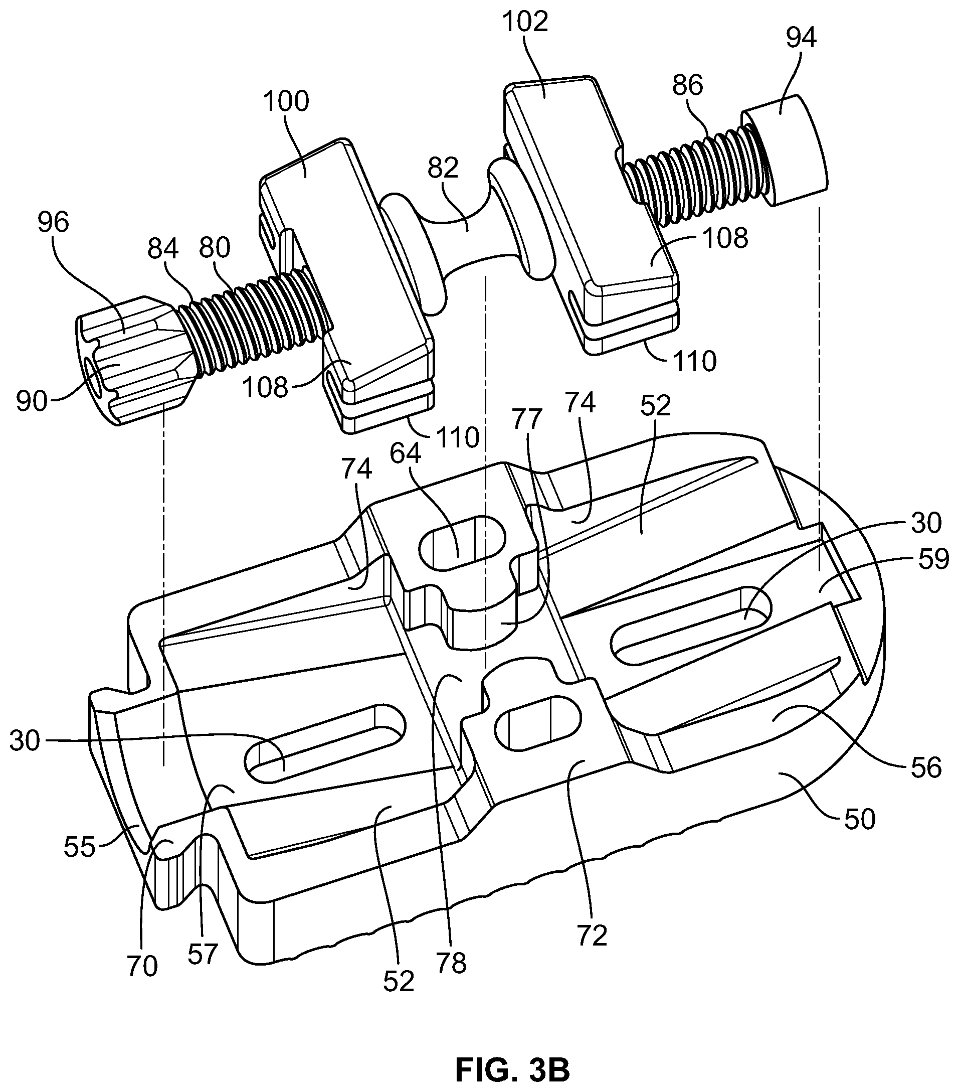
FIGS. 3A-B are exposed views of the top and bottom plates, respectively, of the implant of FIGS. 1A-1B, with the distraction mechanism shown alongside the relevant plate.
FIGS. 4A-B are perspective views of an instrument used for implantation, removal, and distraction of an expandable implant.
FIGS. 5A-B are perspective views of the instrument of FIGS. 4A-B, in which the instrument is being attached to the implant.
FIGS. 6A-B are perspective views of the instrument of FIGS. 4A-B, with the instrument configured for implantation of the implant.
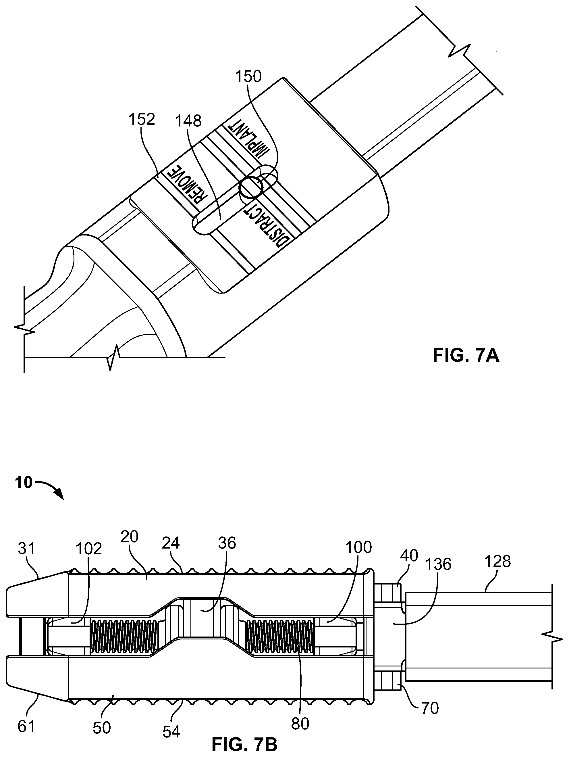
FIGS. 7A-B depict the instrument of FIGS. 4A-B, in which the instrument is configured for distraction of the implant.
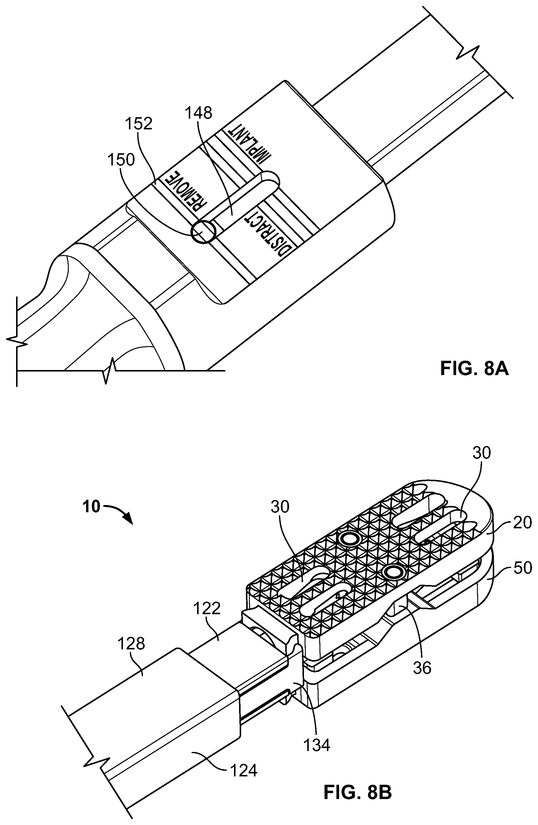
FIGS. 8A-B are perspective views of the instrument of FIGS. 4A-B, with the instrument configured to be removed from the implant.
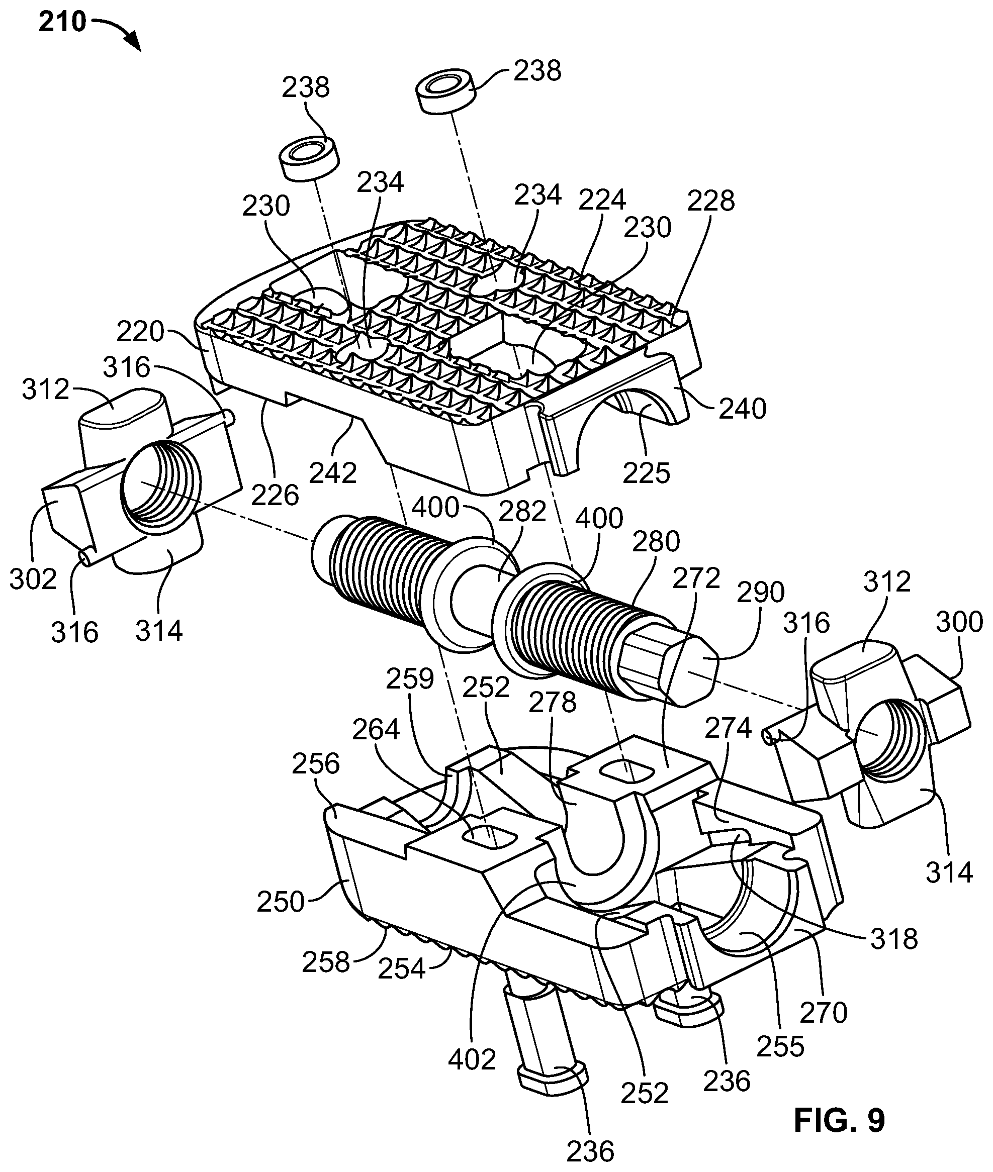
FIG. 9 is an exploded view of another embodiment of an expandable implant according to the present invention.
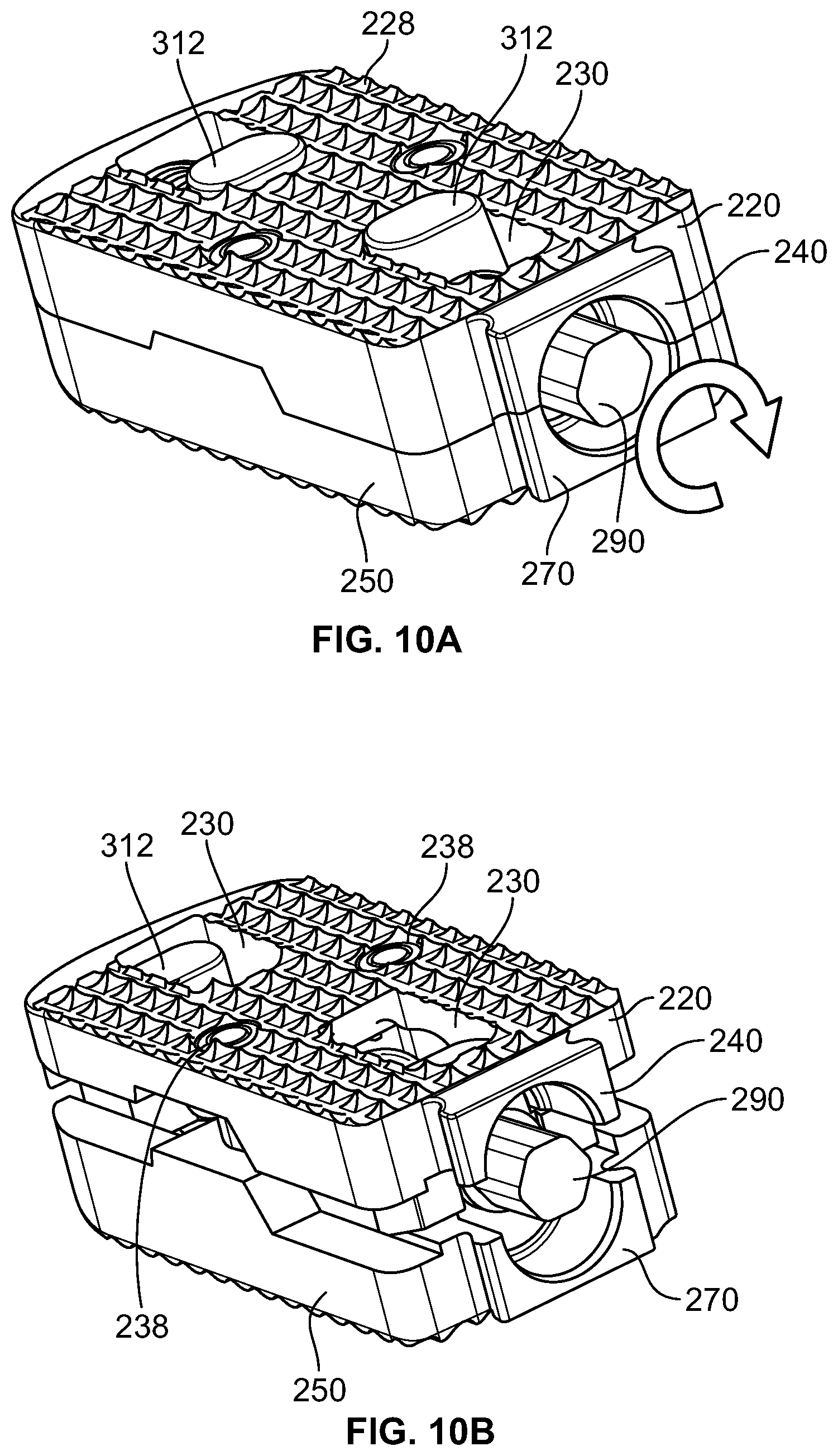
FIGS. 10A-B are perspective views of the implant of FIG. 9 in collapsed and expanded orientations, respectively.
FIGS. 11A-B are cross-sectional views of the implant of FIGS. 10A-B.
FIGS. 12A-B are exposed views of the bottom and top plates, respectively, of the implant of FIG. 9.
FIG. 13A is a perspective view of an alternate expandable implant according to one embodiment of the present invention, while FIG. 13B is an exploded view of the distraction mechanism used with that implant.
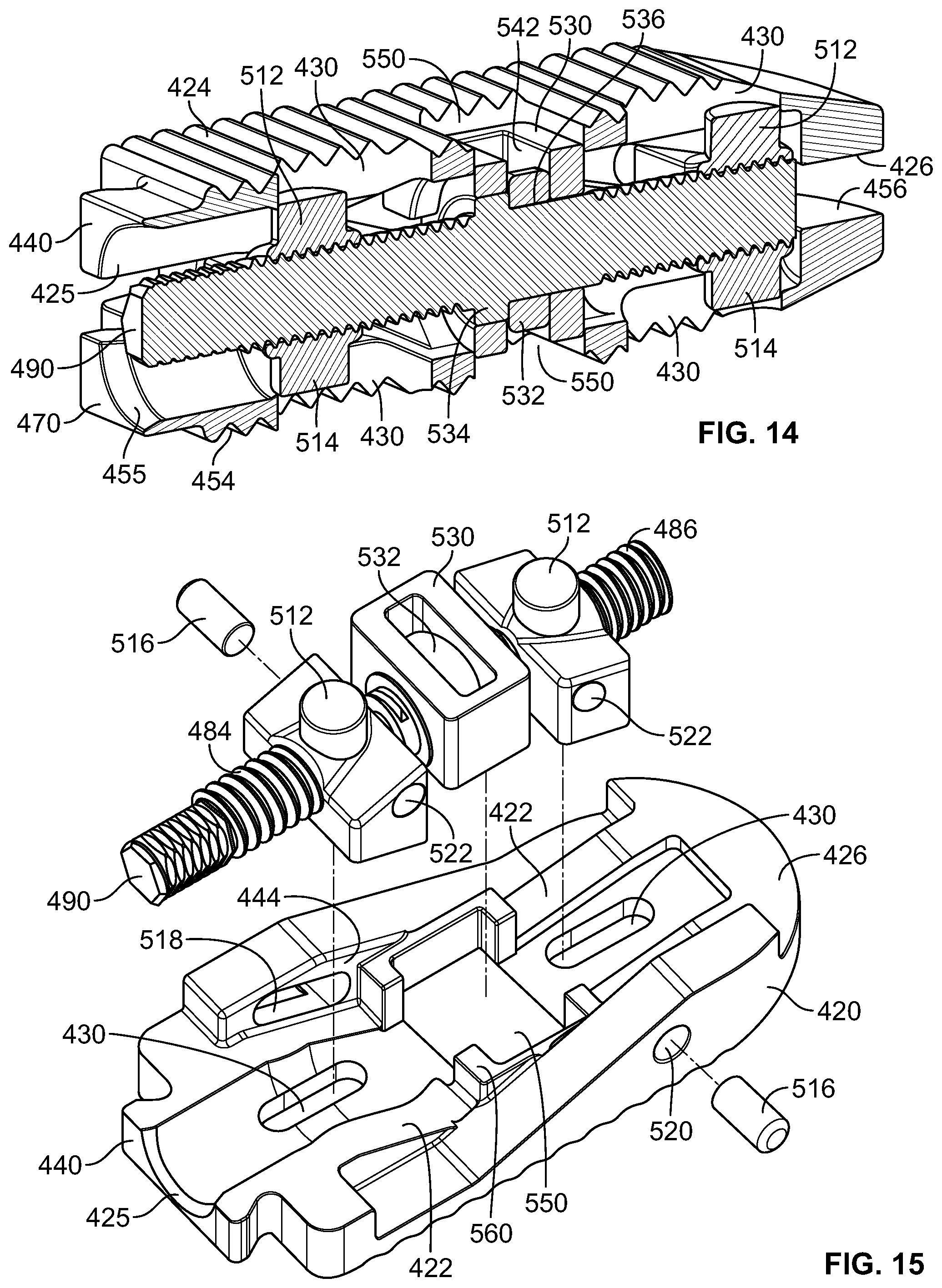
FIG. 14 is a cross-sectional view of the implant of FIG. 13A.
FIG. 15 is an exposed view of one of the plates of the implant of FIG. 13A, the other plate being a mirror image thereof.
DETAILED DESCRIPTION
In describing the preferred embodiments of the invention(s) illustrated and to be described with respect to the drawings, specific terminology will be used for the sake of clarity. However, the invention(s) is not intended to be limited to any specific terms used herein, and it is to be understood that each specific term includes all technical equivalents, which operate in a similar manner to accomplish a similar purpose. For instance, while the terms "top" and "bottom" are used herein, such terms are utilized merely for convenience, and it is contemplated that the various implants disclosed may be situated in several orientations, such that these spatial terms may not apply (e.g., they may be reversed).
Referring to FIGS. 1A-3B, there is shown one embodiment of an expandable implant 10, which in some cases may be used as an intervertebral implant, the expandable implant 10 having, generally: (1) top and bottom plates 20, 50 situated in opposition to one another; (2) a rod or axle 80 arranged between the top and bottom plates 20, 50; and (3) expansion members 100, 102 for contacting angled surfaces 22, 52 on top and bottom plates 20, 50, respectively, and for expanding the implant 10 (e.g., in situ). In use, implant 10 may be inserted between adjacent vertebral bodies and expanded through use of an instrument, such as instrument 120 shown in FIGS. 4A-B, for example. This system provides a surgeon, nurse, or other skilled practitioner (hereinafter "the user") with an improved expandable implant 10 for use in interventional procedures designed to combat various degenerative disorders, for example.
Referring to FIGS. 1A-B, top and bottom plates 20, 50 may include outer bone-contacting surfaces 24, 54 and inner surfaces 26, 56 opposed to the outer surfaces 24, 54. In one embodiment, outer bone-contacting surfaces 24, 54 may include teeth, notches, serrations, keels, or other bone-penetrating features 28, 58 for engaging bone during use. An end of top and bottom plates 20, 50 may also be tapered 31, 61 for facilitating implantation of implant 10, in one embodiment. Top plate 20 may also include, as shown in FIG. 1A, multiple elongate apertures 30 for facilitating bone in-growth or for receiving other biocompatible materials, for example. In some cases, top plate 20 may include four elongate apertures 30, while bottom plate 50 may only include two, as reflected in FIGS. 3A-B, respectively. A separate set of apertures 34, 64 may also be formed in plates 20, 50 for receiving a post(s) 36 and nut(s) 38 construct, as shown in FIGS. 2A-B. In one embodiment, apertures 34 in top plate 20 may be generally thin in comparison to the elongate nature of apertures 64 in bottom plate 50, thereby guiding and facilitating movement of posts 36 in apertures 64. Each of plates 20, 50 may also include a projection 40, 70, which in one embodiment may be dovetail-shaped.
Inner surfaces 26, 56 of top and bottom plates 20, 50, as shown, respectively, in FIGS. 3A-3B may each include angled surfaces 22, 52 on either side of a center of the plate 20, 50. In particular, referring to FIG. 3B, bottom plate 50 may include a raised center 72 having apertures 64, and on either side of center 72 may be an angled surface(s) 52. Such surfaces 52 may also be angled in a direction extending from respective ends of plate 50 to raised center 72. Likewise, referring to FIG. 3A, top plate 20 may include a recessed center 42 having apertures 34, and on either side of recessed center 42 may be an angled surface(s) 22. Further, such surfaces 22 may be angled in a direction extending from respective ends of plate 20 to recessed center 42. Thus, angled surfaces 22, 52 of plates 20, 50 may converge towards one another, in one embodiment, as shown in FIGS. 3A-B.
Angled surfaces 22, 52 of plates 20, 50 may also be bounded by adjacent side walls 44, 74 for guiding expansion members 100, 102, as described in detail below. Further: (1) raised center portion 72 may include a cutout 78 for accommodating an hourglass-shaped structure 82; (2) one end of each plate 20, 50 may include a semi-cylindrical cutout 29, 59 for accommodating part of axle 80; and (3) dovetail-shaped projections 40, 70 may each include a semi-cylindrical opening 25, 55 for receiving another portion of axle 80. Inner surfaces 26, 56 of plates 20, 50 may also include a channel 27, 57 for housing axle 80.
Referring still to FIGS. 3A-B, axle 80 may be situated between plates 20, 50, and may include an hourglass-shaped member 82. First and second threaded sections 84, 86 may also be arranged on opposite sides of hourglass-shaped member 82, such sections 84, 86 having opposed right and left-handed threading. In other words, as an example, threaded section 84 may be situated on one side of hourglass-shaped member 82 and include left-hand threads, while threaded section 86 may be positioned on an opposing side of hourglass-shaped member 82 and include right-hand threads.
Expansion members 100, 102 may also be situated on axle 80, such members 100, 102 each including an internally-threaded bore (not shown) for receiving one of threaded sections 84, 86. In some embodiments, expansion members 100, 102 may include top and bottom surfaces 108, 110 angled in opposition to angled surfaces 22, 52 and in opposition to one another. Stated differently, top surfaces 108 of expansion members 100, 102 may be angled to seat flush with angled surfaces 22 of top plate 20, while bottom surfaces 110 of expansion members 100, 102 may be angled to seat flush with angled surfaces 52 of bottom plate 50, as shown in detail in FIGS. 2A-B. As such, top and bottom surfaces 108, 110 of expansion members 100, 102 may form a wedge.
At one end of axle 80 there may also be an engagement nut 90, while at an opposing end of axle 80 may be stop nut 94. Engagement and/or stop nuts 90, 94 may either be separate components threaded onto axle 80, or, in some embodiments, may be unitarily formed with axle 80. Engagement nut 90 includes ridges or serrations 96 on an exterior surface thereof for attaching with a portion of instrument 120, and stop nut 94 comprises a smooth and enlarged exterior surface for interacting with a portion of expansion members 100, 102. In one embodiment, ridges 96 on engagement nut 90 may form a Torx structure.
To construct implant 10, top and bottom plates 20, 50 may first be situated in opposition to one another with inner surfaces 26, 56 facing towards each other. Axle 80, previously assembled to include expansion members 100, 102, and engagement 90 and stop 94 nuts, may also be situated between plates 20, 50 and within channels 27, 57. In this configuration, top surfaces 108 of expansion members 100, 102 may engage with angled surfaces 22 of top plate 20, and bottom surfaces 110 of expansion members 100, 102 may engage with angled surfaces 52 of bottom plate 50, as shown in FIGS. 2A-B. Further, engagement nut 90 may be surrounded by semi-cylindrical openings 25, 55 of dovetail-shaped projections 40, 70, and stop nut 94 by semi-cylindrical openings 29, 59. An end of posts 36, which in some cases includes an enlarged head 32, may also be accommodated within apertures 64 in bottom plate 50, and a stop surface 65 within each aperture 64 may prevent passage of head 32 completely through the aperture 64 (FIG. 2B). An opposing end of posts 36, which in some instances includes threading, may also be situated within apertures 34 in top plate 20 and be engaged with nuts 38 housed in apertures 34. As such, plates 20, 50 may be connected together via posts 36, which may allow expansion of implant 10 through movement of heads 32 within apertures 64 in bottom plate 50, as shown in detail in the progression between FIGS. 2A-B.
With plates 20, 50 connected together as described above, and in an unexpanded state (FIGS. 1A, 2A), raised center section 72 of bottom plate 50 may be accommodated within recessed center section 42 of top plate 20, and a perimeter of inner surfaces 26, 56 may be in contact with one another. Further, hourglass-shaped member 82 of axle 80 may be situated within the cutout 78 in bottom plate 50. What is more, protrusions 77 extending into cutout 78 may engage a portion of hourglass-shaped member 82 to stabilize axle 80 along a longitudinal axis of plates 20, 50 (FIG. 3B).
In this orientation, rotation of axle 80 in one direction may cause corresponding outward movement of expansion members 100, 102 (e.g., towards the ends of axle 80), and rotation in another opposite direction may cause inward movement of expansion members 100, 102 (e.g., towards hourglass-shaped member 82). Such movement of expansion members 100, 102 may also interact with angled surface 22, 52 on plates 20, 50 to cause corresponding expansion or collapse of implant 10 (e.g., within an intervertebral disc space), as shown in FIGS. 2A-B. In particular, movement of expansion members 100, 102 generally towards the ends of axle 80 may cause such members 100, 102 to ride up angled surfaces 22, 52 on plates 20, 50 and thereby cause expansion of implant 10. Further, with top and bottom surfaces 108, 110 of expansion members 100, 102 being angled in the manner discussed above, the movement of plates 20, 50 may be generally uniform. In other words, were respective planes drawn along outer bone-contacting surfaces 24, 54 of plates 20, 50, upon expansion of implant 10, such planes would remain in generally the same orientation with respect to one another (i.e., due to top and bottom surfaces 108, 110 of expansion members 100, 102 being set flush against angled surfaces 22, 52). It is also contemplated that, in one embodiment, the aforementioned planes (and thus outer bone-contacting surfaces 24, 54) may be arranged at lordotic angles to one another. This may appropriately accommodate lordosis of adjacent vertebral bodies, if present. Such lordotic angles may also be maintained upon expansion of implant 10.
During the above-described expansion of implant 10, axle 80 may rotate within channels 27, 57, and particularly: (1) hourglass-shaped member 82 may rotate within cutout 78; (2) engagement nut 90 within semi-circular openings 25, 55; and (3) stop nut 94 within semi-circular openings 29, 59. Further, as noted above, due to the reverse threading of threaded sections 84, 86, upon rotation of axle 80, expansion members 100, 102 may move towards or away from one another (i.e., in opposing directions). Such movement of expansion members 100, 102 may also be limited by engagement 90 and stop 94 nuts, and hourglass-shaped member 82. In addition, during expansion of implant 10, expansion members 100, 102 may be stabilized via side walls 44, 74 of inner surfaces 26, 76, and posts 36 may limit and/or prevent over-expansion of implant 10. Indeed, as expansion members 100, 102 move plates 20, 50 apart, the head 32 of posts 36 may slide within elongate apertures 64 in plate 50 until such a point as head 32 contacts stop surface 65, as shown in FIG. 2B. Thus, posts 36 may act to prevent over distraction of implant 10. Further, posts 36 may also operate to stabilize implant 10 upon expansion, since sections of posts 36 are engaged with both top and bottom plates 20, 50 during expansion. In other words, posts 36 may serve to provide torsional and/or compressive stability to plates 20, 50 in one embodiment.
As such, in use, implant 10 may be inserted into the intervertebral disc space of a patient, with outer bone-contacting surfaces 24, 54 engaging adjacent vertebrae, and such implant 10 may be expanded in the manner described above. Further details pertaining to this method of expansion, and the insertion of the implant 10 within an intervertebral space, are set forth in subsequent sections.
Referring to FIGS. 4A-B, there is shown an instrument 120 engageable with the aforementioned implant 10, and usable to place implant 10 at the treatment site (e.g., within the intervertebral disc space). Instrument 120 may generally include: (1) a shaft 122 with a sleeve 128 overlying the shaft 122; (2) distal 124 and proximal 126 ends; (3) a socket 130 for engaging with engagement nut 90; and (4) a rotatable handle 132 connected to socket 130, such that rotation of handle 132 may cause rotation of socket 130 and expansion of implant 10 (e.g., when instrument 120 is engaged with engagement nut 90). Distal end 124 of instrument 120 may also include fingers 134, 136 that are engageable with dovetail-shaped projections 40, 70, and may be actuated via a knob 138 situated adjacent proximal end 126 of instrument 120. Thus, instrument 120 may provide a useful tool for a user in the insertion and/or expansion of implant 10, as detailed more fully below.
As shown in FIG. 4A, handle 132 of instrument 120 may be connected to a rod (not shown) extending generally within and along shaft 122 of instrument 120. The rod may extend to distal end 124 of instrument 120 and may terminate in socket 130, which in one embodiment may be configured to engage with engagement nut 90. In some instances, socket 130 may be a Torx-type socket for engaging with an engagement nut 90 having Torx structure. A separate handle 142 may also be provided adjacent proximal end 126, such handle 142 extending generally outward from instrument 120. Instrument 120 may also include a grip 144. Handle 142 and grip 144 may allow the user to effectively grasp instrument 120 during insertion of implant 10 into the intervertebral disc space.
FIG. 4A further depicts a knob 138 adjacent proximal end 126 that is rotatable about a longitudinal axis of shaft 122. An interior of knob 138 may include internal threading for cooperating with an actuator (not shown) connected to sleeve 128. The threading within knob 138 may be configured such that, upon rotation of knob 138 in one direction, the actuator and sleeve 128 may move longitudinally towards distal end 124; and, upon rotation of knob 138 in an opposing direction, the actuator and sleeve 128 may move longitudinally towards proximal end 126.
A viewing window 148 may also be provided with instrument 120, as shown in close-up in FIG. 4B, for indicating to a user of instrument 120 the particular mode in which instrument 120 is situated (e.g., "implant" mode, "distract" mode, or "remove" mode). An indicator 150 may be housed within viewing window 148, and a series of markings 152 may also be situated adjacent the window 148. Further, in one embodiment, wording or other information may be provided proximate viewing window 148 and markings 152 to inform a user of the mode in which instrument 120 is placed.
Referring to FIGS. 5A-B, distal end 124 of shaft 122 of instrument 120 may be provided with resilient fingers 134, 136 running along opposing sides of shaft 122, and positioned within channels (not shown) in shaft 122. Each finger 134, 136 may include an end having generally angled surfaces 154 for engaging with projections 40, 70 on implant 10. In one embodiment, fingers 134, 136 may be shaped to conform to the dovetail shape of projections 40, 70.
In use, referring still to FIGS. 5A-B, distal end 124 of instrument 120 may be positioned adjacent dovetail-shaped projections 40, 70 of implant 10 so that socket 130 of instrument 120 may be attached to engagement nut 90. Specifically, as shown in the progression between FIGS. 5A-B, resilient fingers 134, 136 may be inserted over projections 40, 70 with sleeve 128 in its retracted position. Such position of sleeve 128 may, in one embodiment, correspond to the "remove" mode shown in FIG. 8A. Upon insertion of fingers 134, 136 over projections 40, 70, fingers 134, 136 may translate outwards to accommodate the shape of projections 40, 70. After full insertion of fingers 134, 136 over projections, angled surfaces 154 may seat within or accommodate the shape of projections 40, 70. Stated differently, since fingers 134, 136 may be biased to remain within the channels in shaft 122, after insertion of fingers 134, 136 over projections 40, 70, fingers 134, 136 may return to their normal un-translated state and conform to the shape of projections 40, 70. Such is shown in detail in FIG. 5B.
With socket 130 connected to engagement nut 90 and fingers 134, 136 situated about projections 40, 70, sleeve 128 of instrument 120 may then be translated longitudinally via knob 138 until such a point as sleeve 128 contacts implant 10, as shown in FIGS. 6A-B. This position of sleeve 128 may correspond to the "implant" mode of instrument 120, which may be indicated by the movement of indicator 150 within viewing window 148. In particular, movement of sleeve 128 may cause movement of indicator 150 within window 148, such that indicator 150 becomes aligned with a marking 152 corresponding to the "implant" mode of instrument 120, as shown in FIG. 6A. Further, as sleeve 128 moves longitudinally in the manner described above, fingers 134, 136 may be compressed against projections 40, 70, thereby securing instrument 120 to implant 10. Implant 10 may then be inserted into the intervertebral disc space via instrument 120, such that outer bone-contacting surfaces 24, 54 engage upper and lower vertebral bodies. The approach for implantation of implant 10, in some cases, may be a posterior or posterior-lateral approach, although other approaches are contemplated. In some embodiments, the vertebral bodies may also be prepared (e.g., through the use of cutting instruments) according to traditional spinal procedures prior to implantation of implant 10. It is also contemplated that, during insertion of implant 10, tapered ends 31, 61 of plates 20, 50 may provide easier insertion of implant 10 into the intervertebral space via insertion instrument 120. In addition, the lordotic angle between plates 20, 50 may, in one embodiment, accommodate lordosis of the adjacent vertebrae, if present.
To distract implant 10 once inserted, instrument 120 may be placed in "distract" mode. Referring to FIGS. 7A-B, this involves rotating knob 138 in one direction to move the actuator and sleeve 128 toward proximal end 126 of instrument 120. As sleeve 128 moves toward proximal end 126, indicator 150 may also move within viewing window 148 so as to line up with the particular marking 152 corresponding to "distract" mode. Thus, a user may be informed when instrument 120 is placed in "distract" mode via rotation of knob 138. With sleeve retracted a sufficient distance towards proximal end 126, some pressure may be relieved from between fingers 134, 136 and projections 40, 70, thereby allowing plates 20, 50 to move apart from one another without fingers 134, 136 inhibiting such movement. Stated differently, sleeve 128 may be retracted towards proximal end 126, such that fingers 134, 136 may still retain projections 40, 70 and implant 10, but that pressure therebetween is somewhat relieved so as to allow distraction of implant 10. To achieve such distraction, the user may simply rotate handle 132 (FIG. 4A) causing socket 130 to rotate within engagement nut 90. This rotation of engagement nut 90, as described previously, may cause expansion members 100, 102 to interact with ramped surfaces 22, 52 of plates 20, 50 and force plates 20, 50 apart. Distraction of plates 20, 50 in this manner may also cause distraction of adjacent vertebral bodies. It is thusly possible for implant 10 to accommodate varying degrees of intervertebral spacing, as required during different surgeries or with different patients. Implant 10, in its expanded state as discussed above, is shown in detail in FIG. 7B.
Referring now to FIGS. 8A-B, with implant 10 inserted into the intervertebral disc space, instrument 120 may be placed in "remove" mode, which again may be indicated by movement of indicator 150 within viewing window 148. In particular, knob 138 may be rotated in one direction causing movement of sleeve 128 towards proximal end 126 of instrument 120 and corresponding movement of indicator 150. Further, during movement of sleeve 128 towards proximal end 126, fingers 134, 136 may be fully released and allowed to resiliently deform outwards as instrument 120 is removed from about projections 40, 70. Instrument 120 may then be removed from the surgical site and implant 10 left to affect fusion of the adjacent vertebral bodies. To achieve improved fusion, it is also contemplated that bone-chips, synthetic graft material, or other biocompatible material may be inserted within the intervertebral disc space prior to or during the implantation of implant 10, and such material may adhere to the apertures in plates 20, 50 (e.g., apertures 30) provided for in-growth.
An alternate embodiment implant 210 is shown in FIG. 9. Due to the similarity between the structures of implants 10, 210, like numerals will refer to like elements and, predominantly, only the structural differences between implants 10, 210 will be highlighted. Thus, apart from the below-mentioned distinguishing features, it is contemplated that implants 10, 210 may have the same structure and may operate in the same manner (e.g., as set forth above) to accomplish the same purpose.
Referring to FIG. 9, implant 210 may include top and bottom plates 220, 250, such plates including, inter alia: (1) outer bone-contacting surfaces 224, 254 and opposed inner surfaces 226, 256; (2) projections 240, 270, which in one embodiment may be dovetail-shaped; (3) apertures 234, 264 for receiving posts 236 and nuts 238; (4) recessed and raised center portions 242, 272; and (5) angled surfaces 222, 252 for engaging with expansion members 300, 302. Other similar features to implant 10 are also present in implant 210; and, although not discussed in detail herein, such features are indicated by like reference numerals in the figures.
Several differentiating features of implant 210 will now be described, such features providing improvements in the operation of expandable implant 210. Referring to FIG. 9, implant 210 may include an axle 280 disposed between top and bottom plates 220, 250, with axle 280 including a center member 282 that is slightly different in shape than hourglass-shaped member 80 of implant 10. Even so, center member 282 of axle 280 may include opposed discs 400 for engaging with cutouts 402 formed in bottom plate 250, and a center portion having a reduced diameter for seating within cutout 278, as shown in detail in FIG. 12A. With center member 282 situated in bottom plate 250 as described, axle 280 may be longitudinally stabilized with respect to plate 250 (e.g., through the interaction of opposed discs 400 and cutouts 402), as is the case with axle 80 of implant 10.
Implant 210 may also include expansion members 300, 302 having top and bottom surfaces 308, 310 that are angled in the manner described with reference to expansion members 100, 102, as shown in FIGS. 11A-B, but expansion members 300, 302 may also have vertically-extensive projections 312, 314 extending outward therefrom. Expansion members 300, 302 may also include a set (or one or more) of pins 316 extending from the sides of members 300, 302. Vertically-extensive projections 312, 314 of expansion members 300, 302 may be received in elongate apertures 230 formed in top and bottom plates 220, 250, such apertures 230 being configured to allow translation of vertically-extensive projections 312, 314 during expansion of implant 210. Pins 316 of expansion members 300, 302 may ride along slots 318 formed within side walls 244, 274 situated adjacent angled surfaces 222, 252 for guiding expansion members 300, 302 during expansion of implant 210, as shown in detail in FIGS. 9 and 12A-B.
In use, implant 210 may be implanted and/or expanded in much the same manner as implant 10. Particularly, it is contemplated that insertion instrument 120 may be modified only slightly to properly operate with and engage implant 210, and to distract such implant 210 after implantation. For example, while it is contemplated that engagement nut 290 of implant 210 may include Torx structure, it is shown in the figures as a hexagonal nut 290 (FIGS. 9, 11A-B). Thus, socket 130 of instrument 120 may be modified to accommodate this structure, and to engage with engagement nut 290 in the manner described in relation to implant 10. To be exact, such modified socket 130 may be inserted over engagement nut 290, and rotated via handle 132 so as to expand implant 210. It is also contemplated that instrument 120 may be placed into the various modes (e.g., "implant" mode, "distract" mode, and/or "remove" mode) upon engaging, distracting, and/or separating from implant 210, as discussed previously. Significantly, however, during expansion of implant 210 through the use of instrument 120, several structures of implant 210 may operate differently to provide a more stabilized and improved distraction procedure.
In one embodiment, referring now to FIGS. 9 and 12A-B, during expansion of implant 210 via the interaction between socket 130 and engagement nut 290, expansion members 300, 302 may engage with angled surfaces 222, 252; but, during separation of expansion members 300, 302 via the reverse threading of threaded sections 284, 286, pins 316 extending from expansion members 300, 302 may ride along slots 318 formed in respective side walls 244, 274 of top and bottom plates 220, 250. The engagement between pins 316 and slots 318 may act to stabilize the movement of expansion members 300, 302, and may also serve to limit the expansion of implant 210. Indeed, slots 318 may terminate at one section of side walls 244, 274, and pins 316 may abut this section upon full expansion of implant 210 to prohibit further movement of expansion members 300, 302 (e.g., away from one another). In one embodiment, pins 316 may be situated on diagonally opposite sides of each respective expansion member 300, 302, although it is contemplated that additional pins 316 may be used (e.g., on all four (4) corners of expansion members 300, 302). The engagement between pins 516 and slots 518 may also, at least partially, serve to keep plates 220, 250 in registration with one another during distraction.
An additional stabilization and/or expansion-limiting feature may be included with implant 210 in the form of elongate apertures 230. In particular, referring to FIGS. 10A-11B, during expansion of implant 210 via the use of instrument 120, vertically-extensive projections 312, 314 of expansion members 300, 302 may interact with elongate apertures 230 in top and bottom plates 220, 250 to stabilize such members 300, 302 and plates 220, 250. As shown in the progression between FIGS. 10A-10B and 11A-11B, vertically-extensive projections 312, 314 may be arranged within elongate apertures 230 of plates 220, 250; and, upon expansion of implant 210, vertically-extensive projections 312, 314 may translate within apertures 230, such that plates 220, 250 and expansion members 300, 302 are stabilized during distraction. Upon reaching an end of apertures 230, expansion members 300, 302 may also be limited from further outward movement. Apertures 230 may also, like apertures 30 of implant 10, operate to receive bone graft or other osteoinductive material to facilitate fusion of adjacent vertebral bodies upon implantation of implant 210. Although not discussed in detail herein, the remainder of steps pertaining to the implantation and/or expansion of implant 210, and its interaction with instrument 120, is again substantially identical to that discussed above with respect to implant 10.
Another embodiment of an expandable implant, implant 410, is shown in FIGS. 13A-15. Here, like numerals will refer to like elements, with the structural differences between implants 10, 210, 410 being discussed. Thus, as with above, apart from the distinguishing features detailed in subsequent sections, it is contemplated that implants 10, 210, 410 may have the same structure and operate in the same manner to accomplish the same purpose. Here, it is worthwhile to note that, while FIG. 15 only depicts top plate 420, bottom plate 450 is a mirror image thereof, and thus, FIG. 15 is an accurate representation of both plates 420, 450 (e.g., with like reference numerals referring to like elements).
Referring to FIGS. 13A and 15, implant 410 may include top and bottom plates 420, 450 with angled inner surfaces 422, 452 for engaging with expansion members 500, 502, much like implants 10, 210. Further, expansion members 500, 502 of implant 410 may also include vertically-extensive projections 512, 514 for engaging with elongate apertures 430 in plates 420, 450, such that upon expansion of implant 410, vertically-extensive projections 512, 514 may translate within apertures 430. Other similar features to implants 10, 210 are also included with implant 410, such as: (1) outer bone-contacting surfaces 424, 454 with teeth or serrations 428, 458; (2) tapered ends 431, 461 of plates 420, 450; (3) dovetail-shaped projections 440, 470; (4) slots 518 in side walls 444, 474 of plates 420, 450; and (5) expansion members 500, 502 including pins 516 for engaging with slots 518. Yet, other features, such as the distraction mechanism of implant 410, may operate differently than found with implants 10, 210.
Referring to FIG. 13B, the distraction mechanism of implant 410 may include a rod or axle 480, a capture mechanism 530, and a containment ring 532. Axle 480, like axles 80, 280, may be threaded in one embodiment, and may include separate sections 484, 486 with left-handed and right-handed threads. An engagement nut 490 structure may also be disposed on one end of axle 480, and a center of axle may include a radially-extending flange 534 and a press-fit region 536.
Capture mechanism 530 may include a set of apertures 538, 540 for receiving a portion of axle 480, and a slot 542 for receiving containment ring 532. Slot 542 may be dimensioned to allow free movement of containment ring 532 and axle 480 once situated therein. In one embodiment, aperture 538 of capture mechanism 530 may have a diameter that is larger than aperture 540 so as to allow flange 534 to be received in aperture 538. Further, each aperture 538, 540 may be smaller in diameter than an outer diameter of containment ring 532. In a particular embodiment, containment ring 532 includes an inner diameter such that, upon insertion of press-fit region 536 into containment ring 532, a dimensional interference is established therebetween.
Apart from the differences between distraction mechanisms amongst implants 10, 210, 410, implant 410 may also include plates 420, 450 with apertures 550 for receiving a portion of capture mechanism 530, as shown in FIG. 14. Inner surfaces 426, 456 of plates 420, 450 may also include structure (e.g. a housing 560) for stabilizing capture mechanism 530 (and thus axle 480) in a longitudinal direction, as shown in FIG. 15. In one embodiment, plates 420, 450 also include openings 520 through which pins 516 may be inserted. Similarly, expansion members 500, 502 may include openings 522 for receiving pins 516.
In use, the distraction mechanism of implant 410 may be situated between plates 420, 450 such that axle 480 is inserted into capture mechanism 530 and through containment ring 532, as shown in FIG. 14. In particular, containment ring 532 may be disposed within slot 542 in capture mechanism 530, and axle 480 may be inserted through apertures 538, 540. To be exact, axle 480 may be inserted through containment ring 532 until such a point as press-fit region 536 is situated within containment ring 532 and flange 534 is housed within aperture 538 and abuts containment ring 532. In this orientation, press-fit region 536 may interact with containment ring 532 to establish a dimensional interference between such structures, such that axle 480 may be securely retained within capture mechanism 530. To be exact, the interaction between flange 534 and containment ring 532 may prevent movement of axle 480 in one direction, and the cooperation between press-fit region 536, containment ring 532, and slot 542 may prevent movement of axle 480 in another opposing direction. With axle situated in capture mechanism 530 in the manner described above, capture mechanism 530 may then be inserted into apertures 550 in plates 420, 450.
Capture mechanism 530, axle 480, and expansion members 500, 502 may be situated between plates 420, 450, with the inner surfaces 426, 456 of plates 420, 450 facing one another, as discussed above, and pins 516 may be inserted through openings 520 in plates 420, 450 and into openings 522 in expansion members 500, 502. Indeed, pins 516 may be press-fit into openings 522 in expansion members 500, 502, such that pins 516 are firmly retained in expansion members 500, 502. Pins 516 are also designed to ride within slots 518 to limit movement of expansion members 500, 502, and such pins 516 may also serve to keep plates 420, 450 firmly connected together. In other words, as at least one pin 516 on each expansion member 500, 502 engages with a slot 518 in top plate 420, and at least one pin 516 with a slot 518 in bottom plate 450, such plates 420, 450 may be securely retained together via the interaction between pins 516 and slots 518. A terminal portion of slots 518 may also serve to prevent over-expansion of implant 410, as discussed above with respect to implant 210.
Implant 410 may also interact with instrument 120 in the same manner as implants 10, 210 (e.g., for purposes of implantation and/or distraction). For instance, rotation of handle 132 with respect to engagement nut 490 in one direction may cause expansion members 500, 502 to move outwardly, and pins 516 to engage with slots 518. Such movement of expansion members 500, 502 may also cause outward movement or distraction of plates 420, 450, as with implants 10, 210; and additional rotation of handle 132 may cause pins 516 of expansion members 500, 502 to engage with a terminal portion of slots 518 to prevent further outward movement of expansion members 500, 502.
What is more, during the aforementioned movement of expansion members 500, 502, vertically-extensive projections 512, 514 may translate within apertures 430 in plates 420, 450, and apertures 550 in plates 420, 450 may interact with capture mechanism 530. Stated differently, as expansion members 500, 502 engage with angled surfaces 422, 522 to distract implant 410 (e.g., via use of instrument 120), apertures 550 in plates 420, 450 may slide along portions of capture mechanism 530, vertically-extensive projections 512, 514 may translate within apertures 430, and pins 516 may ride within slots 518. Such movement of expansion members 500, 502 may therefore serve to stabilize implant 410 during distraction. For instance, the interaction between vertically-extensive projections 512, 514 and apertures 430, and apertures 550 and capture mechanism 530, may provide torsional and/or compressive stability to implant 410 during distraction, and pins 516 may act as distraction-limiting features. Thus, as with implants 10, 210, implant 410 may provide an expandable implant with improved features for maintaining stability and/or controlling distraction during replacement of an intervertebral disc.
In the devices shown in the figures, particular structures are shown as being adapted for use in the implantation, distraction, and/or removal of an expandable implant according to the present invention(s). The invention(s) also contemplates the use of any alternative structures for such purposes, including structures having different lengths, shapes, and/or configurations. For example, as alluded to above, although certain structures are used for socket 130 and engagement nut 90, 290, 490 (e.g., Torx or hexagonal), it is contemplated that a variety of different socket/nut combinations may be used, such as square, triangular, etc.
In addition, while angled surfaces 22, 52, 222, 252, 422, 452 are shown in the figures as being predominantly flat, it is also contemplated that surfaces 22, 52, 222, 252, 422, 452 may be curved in one embodiment so as to facilitate expansion of implants 10, 210, 410. Top and bottom surfaces 108, 110, 308, 310, 508, 510 of expansion members 100, 102, 300, 302, 500, 502 may likewise be shaped to accommodate the curvature of angled surfaces 22, 52, 222, 252, 422, 452, as previously discussed with respect to implants 10, 210, 410.
Although the invention(s) herein has been described with reference to particular embodiments, it is to be understood that these embodiments are merely illustrative of the principles and applications of the present invention(s). It is therefore to be understood that numerous modifications may be made to the illustrative embodiments and that other arrangements may be devised without departing from the spirit and scope of the present invention(s) as defined by the appended claims.
It will also be appreciated that the various dependent claims and the features set forth therein can be combined in different ways than presented in the initial claims. It will also be appreciated that the features described in connection with individual embodiments may be shared with others of the described embodiments.
* * * * *
D00000
D00001
D00002
D00003
D00004
D00005
D00006
D00007
D00008
D00009
D00010
D00011
D00012

D00013

D00014

D00015
XML
uspto.report is an independent third-party trademark research tool that is not affiliated, endorsed, or sponsored by the United States Patent and Trademark Office (USPTO) or any other governmental organization. The information provided by uspto.report is based on publicly available data at the time of writing and is intended for informational purposes only.
While we strive to provide accurate and up-to-date information, we do not guarantee the accuracy, completeness, reliability, or suitability of the information displayed on this site. The use of this site is at your own risk. Any reliance you place on such information is therefore strictly at your own risk.
All official trademark data, including owner information, should be verified by visiting the official USPTO website at www.uspto.gov. This site is not intended to replace professional legal advice and should not be used as a substitute for consulting with a legal professional who is knowledgeable about trademark law.