Inflatable air mattress system architecture
Nunn , et al. January 5, 2
U.S. patent number 10,881,219 [Application Number 16/230,086] was granted by the patent office on 2021-01-05 for inflatable air mattress system architecture. This patent grant is currently assigned to Sleep Number Corporation. The grantee listed for this patent is Sleep Number Corporation. Invention is credited to Matthew Glen Hilden, Paul James Mahoney, Rob Nunn, Matthew Wayne Tilstra.


| United States Patent | 10,881,219 |
| Nunn , et al. | January 5, 2021 |
Inflatable air mattress system architecture
Abstract
A method may comprise receiving, at a central controller, a command, from a remote control, to adjust a feature of a first component of an air mattress framework; relaying, from the central controller, the command to the first component; receiving from the first component at the central controller, an indication of the success of the command; and relaying the indication from the central controller to the remote control.
| Inventors: | Nunn; Rob (Eden Prairie, MN), Tilstra; Matthew Wayne (Rogers, MN), Hilden; Matthew Glen (Robbinsdale, MN), Mahoney; Paul James (Stillwater, MN) | ||||||||||
|---|---|---|---|---|---|---|---|---|---|---|---|
| Applicant: |
|
||||||||||
| Assignee: | Sleep Number Corporation
(Minneapolis, MN) |
||||||||||
| Family ID: | 1000005279924 | ||||||||||
| Appl. No.: | 16/230,086 | ||||||||||
| Filed: | December 21, 2018 |
Prior Publication Data
| Document Identifier | Publication Date | |
|---|---|---|
| US 20190125097 A1 | May 2, 2019 | |
Related U.S. Patent Documents
| Application Number | Filing Date | Patent Number | Issue Date | ||
|---|---|---|---|---|---|
| 14211367 | Mar 14, 2014 | 10201234 | |||
| 61781503 | Mar 14, 2013 | ||||
| Current U.S. Class: | 1/1 |
| Current CPC Class: | A47C 27/081 (20130101); A47C 31/008 (20130101); A47C 27/083 (20130101); G05B 23/0267 (20130101); A47C 27/082 (20130101) |
| Current International Class: | A47C 31/00 (20060101); G05B 23/02 (20060101); A47C 27/08 (20060101) |
References Cited [Referenced By]
U.S. Patent Documents
| 3727606 | April 1973 | Sielaff |
| 4146885 | March 1979 | Lawson, Jr. |
| 4299233 | November 1981 | Lemelson |
| 4657026 | April 1987 | Tagg |
| 4662012 | May 1987 | Tarbet |
| 4766628 | August 1988 | Walker |
| 4788729 | December 1988 | Walker |
| 4829616 | May 1989 | Walker |
| 4890344 | January 1990 | Walker |
| 4897890 | February 1990 | Walker |
| 4908895 | March 1990 | Walker |
| 4991244 | February 1991 | Walker |
| 5062169 | November 1991 | Kennedy et al. |
| 5144706 | September 1992 | Walker et al. |
| 5170522 | December 1992 | Walker |
| 5197490 | March 1993 | Steiner et al. |
| 5459452 | October 1995 | DePonte |
| 5509154 | April 1996 | Shafer et al. |
| 5515865 | May 1996 | Scanlon |
| 5564140 | October 1996 | Shoenhair et al. |
| 5642546 | July 1997 | Shoenhair |
| 5652484 | July 1997 | Shafer et al. |
| 5675855 | October 1997 | Culp |
| 5684460 | November 1997 | Scanlon |
| 5699038 | December 1997 | Ulrich et al. |
| 5724990 | March 1998 | Ogino |
| 5765246 | June 1998 | Shoenhair |
| 5771511 | June 1998 | Kummer et al. |
| 5796340 | August 1998 | Miller |
| 5844488 | December 1998 | Musick |
| 5848450 | December 1998 | Oexman et al. |
| 5903941 | May 1999 | Shafer et al. |
| 5904172 | May 1999 | Gifft et al. |
| 5948303 | September 1999 | Larson |
| 5964720 | October 1999 | Pelz |
| 5989193 | November 1999 | Sullivan |
| 6024699 | February 2000 | Surwit et al. |
| 6037723 | March 2000 | Shafer et al. |
| 6058537 | May 2000 | Larson |
| 6062216 | May 2000 | Corn |
| 6108844 | August 2000 | Kraft et al. |
| 6120441 | September 2000 | Griebel |
| 6146332 | November 2000 | Pinsonneault et al. |
| 6147592 | November 2000 | Ulrich et al. |
| 6161231 | December 2000 | Kraft et al. |
| 6202239 | March 2001 | Ward et al. |
| 6208250 | March 2001 | Dixon et al. |
| 6234642 | May 2001 | Bokaemper |
| 6272378 | August 2001 | Baumgart-Schmitt |
| 6386201 | May 2002 | Fard |
| 6396224 | May 2002 | Luff et al. |
| 6397419 | June 2002 | Mechache |
| 6438776 | August 2002 | Ferrand et al. |
| 6450957 | September 2002 | Yoshimi et al. |
| 6468234 | October 2002 | Ford et al. |
| 6483264 | November 2002 | Shafer et al. |
| 6485441 | November 2002 | Woodward |
| 6546580 | April 2003 | Shimada |
| 6547743 | April 2003 | Brydon |
| 6561047 | May 2003 | Gladney |
| 6566833 | May 2003 | Bartlett |
| 6686711 | February 2004 | Rose et al. |
| 6708357 | March 2004 | Gaboury et al. |
| 6719708 | April 2004 | Jansen |
| 6763541 | July 2004 | Mahoney et al. |
| 6778090 | August 2004 | Newham |
| 6804848 | October 2004 | Rose |
| 6832397 | December 2004 | Gaboury et al. |
| 6840117 | January 2005 | Hubbard, Jr. |
| 6840907 | January 2005 | Brydon |
| 6847301 | January 2005 | Olson |
| 6878121 | April 2005 | Krausman |
| 6883191 | April 2005 | Gaboury et al. |
| 6993380 | January 2006 | Modarres |
| 7041049 | May 2006 | Raniere |
| 7077810 | July 2006 | Lange et al. |
| 7150718 | December 2006 | Okada |
| 7237287 | July 2007 | Weismiller et al. |
| 7253366 | August 2007 | Bhai |
| 7304580 | December 2007 | Sullivan et al. |
| 7314451 | January 2008 | Halperin et al. |
| 7321811 | January 2008 | Rawls-Meehan |
| 7330127 | February 2008 | Price et al. |
| 7389554 | June 2008 | Rose |
| 7396331 | July 2008 | MacK |
| 7429247 | September 2008 | Okada et al. |
| 7437787 | October 2008 | Bhai |
| 7465280 | December 2008 | Rawls-Meehan |
| 7480951 | January 2009 | Weismiller |
| 7506390 | March 2009 | Dixon et al. |
| 7520006 | April 2009 | Menkedick et al. |
| 7524279 | April 2009 | Auphan |
| 7532934 | May 2009 | Lee et al. |
| 7538659 | May 2009 | Ulrich |
| 7568246 | August 2009 | Weismiller et al. |
| 7637859 | December 2009 | Lindback et al. |
| 7652581 | January 2010 | Gentry et al. |
| 7666151 | February 2010 | Sullivan et al. |
| 7669263 | March 2010 | Menkedick et al. |
| 7676872 | March 2010 | Block et al. |
| 7685663 | March 2010 | Rawls-Meehan |
| 7699784 | April 2010 | Wan et al. |
| 7717848 | May 2010 | Heruth et al. |
| 7749154 | July 2010 | Cornel |
| 7784128 | August 2010 | Kramer |
| 7785257 | August 2010 | Mack et al. |
| 7805785 | October 2010 | Rawls-Meehan |
| 7841031 | November 2010 | Rawls-Meehan |
| 7849545 | December 2010 | Flocard et al. |
| 7854031 | December 2010 | Rawls-Meehan |
| 7860723 | December 2010 | Rawls-Meehan |
| 7862523 | January 2011 | Ruotoistenmaki |
| 7865988 | January 2011 | Koughan et al. |
| 7868757 | January 2011 | Radivojevic et al. |
| 7869903 | January 2011 | Turner et al. |
| 7930783 | April 2011 | Rawls-Meehan |
| 7933669 | April 2011 | Rawls-Meehan |
| 7953613 | May 2011 | Gizewski |
| 7954189 | June 2011 | Rawls-Meehan |
| 7956755 | June 2011 | Lee et al. |
| 7967739 | June 2011 | Auphan |
| 7979169 | July 2011 | Rawls-Meehan |
| 8019486 | September 2011 | Rawls-Meehan |
| 8020230 | September 2011 | Rawls-Meehan |
| 8028363 | October 2011 | Rawls-Meehan |
| 8032263 | October 2011 | Rawls-Meehan |
| 8032960 | October 2011 | Rawls-Meehan |
| 8046114 | October 2011 | Rawls-Meehan |
| 8046115 | October 2011 | Rawls-Meehan |
| 8046116 | October 2011 | Rawls-Meehan |
| 8046117 | October 2011 | Rawls-Meehan |
| 8050805 | November 2011 | Rawls-Meehan |
| 8052612 | November 2011 | Tang |
| 8065764 | November 2011 | Kramer |
| 8069852 | December 2011 | Burton |
| 8073535 | December 2011 | Jung et al. |
| 8078269 | December 2011 | Suzuki et al. |
| 8078336 | December 2011 | Rawls-Meehan |
| 8078337 | December 2011 | Rawls-Meehan |
| 8083682 | December 2011 | Dalal et al. |
| 8090478 | January 2012 | Skinner et al. |
| 8092399 | January 2012 | Sasaki |
| 8094013 | January 2012 | Lee |
| 8096960 | January 2012 | Loree et al. |
| 8146191 | April 2012 | Bobey et al. |
| 8150562 | April 2012 | Rawls-Meehan |
| 8166589 | May 2012 | Hijlkema |
| 8181296 | May 2012 | Rawls-Meehan |
| 8266742 | September 2012 | Andrienko |
| 8272892 | September 2012 | McNeely et al. |
| 8276585 | October 2012 | Buckley |
| 8279057 | October 2012 | Hirose |
| 8280748 | October 2012 | Allen |
| 8281433 | October 2012 | Riley et al. |
| 8282452 | October 2012 | Grigsby et al. |
| 8284047 | October 2012 | Collins, Jr. |
| 8287452 | October 2012 | Young et al. |
| 8336369 | December 2012 | Mahoney |
| 8341784 | January 2013 | Scott |
| 8341786 | January 2013 | Oexman et al. |
| 8348840 | January 2013 | Heit et al. |
| 8350709 | January 2013 | Receveur |
| 8375488 | February 2013 | Rawls-Meehan |
| 8376954 | February 2013 | Lange et al. |
| 8382484 | February 2013 | Wetmore et al. |
| 8386008 | February 2013 | Yuen et al. |
| 8398538 | March 2013 | Dothie |
| 8403865 | March 2013 | Halperin et al. |
| 8413274 | April 2013 | Weismiller et al. |
| 8421606 | April 2013 | Collins, Jr. et al. |
| 8428696 | April 2013 | Foo |
| 8444558 | May 2013 | Young et al. |
| 8517953 | August 2013 | Lange et al. |
| 8620615 | December 2013 | Oexman |
| 8672853 | March 2014 | Young |
| 8679034 | March 2014 | Halperin et al. |
| 8682457 | March 2014 | Rawls-Meehan |
| 8769747 | July 2014 | Mahoney et al. |
| 8840564 | September 2014 | Pinhas et al. |
| 8931329 | January 2015 | Mahoney et al. |
| 8966689 | March 2015 | McGuire et al. |
| 8973183 | March 2015 | Palashewski et al. |
| 8984687 | March 2015 | Stusynski et al. |
| 9737154 | August 2017 | Mahoney et al. |
| 2002/0124311 | September 2002 | Peftoulidis |
| 2003/0045806 | March 2003 | Brydon |
| 2003/0115672 | June 2003 | Newkirk |
| 2003/0128125 | July 2003 | Burbank et al. |
| 2003/0166995 | September 2003 | Jansen |
| 2003/0182728 | October 2003 | Chapman et al. |
| 2003/0221261 | December 2003 | Tarbet et al. |
| 2004/0049132 | March 2004 | Barron et al. |
| 2005/0022606 | February 2005 | Partin et al. |
| 2005/0038326 | February 2005 | Mathur |
| 2005/0115561 | June 2005 | Stahmann et al. |
| 2005/0190068 | September 2005 | Gentry et al. |
| 2005/0283039 | December 2005 | Cornel |
| 2006/0020178 | January 2006 | Sotos et al. |
| 2006/0031996 | February 2006 | Rawls-Meehan |
| 2006/0047217 | March 2006 | Mirtalebi |
| 2006/0152378 | July 2006 | Lokhorst |
| 2006/0162074 | July 2006 | Bader |
| 2007/0118054 | May 2007 | Pinhas et al. |
| 2007/0149883 | June 2007 | Yesha |
| 2007/0179334 | August 2007 | Groves et al. |
| 2007/0180047 | August 2007 | Dong et al. |
| 2007/0180618 | August 2007 | Weismiller et al. |
| 2007/0276202 | November 2007 | Raisanen et al. |
| 2008/0052837 | March 2008 | Blumberg |
| 2008/0071200 | March 2008 | Rawls-Meehan |
| 2008/0077020 | March 2008 | Young et al. |
| 2008/0092291 | April 2008 | Rawls-Meehan |
| 2008/0092292 | April 2008 | Rawls-Meehan |
| 2008/0092293 | April 2008 | Rawls-Meehan |
| 2008/0092294 | April 2008 | Rawls-Meehan |
| 2008/0093784 | April 2008 | Rawls-Meehan |
| 2008/0097774 | April 2008 | Rawls-Meehan |
| 2008/0097778 | April 2008 | Rawls-Meehan |
| 2008/0097779 | April 2008 | Rawls-Meehan |
| 2008/0104750 | May 2008 | Rawls-Meehan |
| 2008/0104754 | May 2008 | Rawls-Meehan |
| 2008/0104755 | May 2008 | Rawls-Meehan |
| 2008/0104756 | May 2008 | Rawls-Meehan |
| 2008/0104757 | May 2008 | Rawls-Meehan |
| 2008/0104758 | May 2008 | Rawls-Meehan |
| 2008/0104759 | May 2008 | Rawls-Meehan |
| 2008/0104760 | May 2008 | Rawls-Meehan |
| 2008/0104761 | May 2008 | Rawls-Meehan |
| 2008/0109959 | May 2008 | Rawls-Meehan |
| 2008/0109964 | May 2008 | Flocard et al. |
| 2008/0109965 | May 2008 | Mossbeck |
| 2008/0115272 | May 2008 | Rawls-Meehan |
| 2008/0115273 | May 2008 | Rawls-Meehan |
| 2008/0115274 | May 2008 | Rawls-Meehan |
| 2008/0115275 | May 2008 | Rawls-Meehan |
| 2008/0115276 | May 2008 | Rawls-Meehan |
| 2008/0115277 | May 2008 | Rawls-Meehan |
| 2008/0115278 | May 2008 | Rawls-Meehan |
| 2008/0115279 | May 2008 | Rawls-Meehan |
| 2008/0115280 | May 2008 | Rawls-Meehan |
| 2008/0115281 | May 2008 | Rawls-Meehan |
| 2008/0115282 | May 2008 | Rawls-Meehan |
| 2008/0120775 | May 2008 | Rawls-Meehan |
| 2008/0120776 | May 2008 | Rawls-Meehan |
| 2008/0120777 | May 2008 | Rawls-Meehan |
| 2008/0120778 | May 2008 | Rawls-Meehan |
| 2008/0120779 | May 2008 | Rawls-Meehan |
| 2008/0120784 | May 2008 | Warner et al. |
| 2008/0122616 | May 2008 | Warner |
| 2008/0126122 | May 2008 | Warner et al. |
| 2008/0126132 | May 2008 | Warner |
| 2008/0127418 | June 2008 | Rawls-Meehan |
| 2008/0127424 | June 2008 | Rawls-Meehan |
| 2008/0147442 | June 2008 | Warner |
| 2008/0162171 | July 2008 | Rawls-Meehan |
| 2008/0189865 | August 2008 | Bhai |
| 2008/0275314 | November 2008 | Mack et al. |
| 2008/0281611 | November 2008 | Rawls-Meehan |
| 2008/0281612 | November 2008 | Rawls-Meehan |
| 2008/0281613 | November 2008 | Rawls-Meehan |
| 2008/0288272 | November 2008 | Rawls-Meehan |
| 2008/0288273 | November 2008 | Rawls-Meehan |
| 2008/0306351 | December 2008 | Izumi |
| 2008/0307582 | December 2008 | Flocard et al. |
| 2009/0018853 | January 2009 | Rawls-Meehan |
| 2009/0018854 | January 2009 | Rawls-Meehan |
| 2009/0018855 | January 2009 | Rawls-Meehan |
| 2009/0018856 | January 2009 | Rawls-Meehan |
| 2009/0018857 | January 2009 | Rawls-Meehan |
| 2009/0018858 | January 2009 | Rawls-Meehan |
| 2009/0024406 | January 2009 | Rawls-Meehan |
| 2009/0037205 | February 2009 | Rawls-Meehan |
| 2009/0043595 | February 2009 | Rawls-Meehan |
| 2009/0064420 | March 2009 | Rawls-Meehan |
| 2009/0100599 | April 2009 | Rawls-Meehan |
| 2009/0121660 | May 2009 | Rawls-Meehan |
| 2009/0139029 | June 2009 | Rawls-Meehan |
| 2009/0203972 | August 2009 | Henehgan et al. |
| 2009/0237264 | September 2009 | Bobey |
| 2009/0275808 | November 2009 | DiMaio et al. |
| 2009/0314354 | December 2009 | Chaffee |
| 2010/0025900 | February 2010 | Rawls-Meehan |
| 2010/0090383 | April 2010 | Rawls-Meehan |
| 2010/0094139 | April 2010 | Brauers et al. |
| 2010/0099954 | April 2010 | Dickinson et al. |
| 2010/0152546 | June 2010 | Behan et al. |
| 2010/0170043 | July 2010 | Young et al. |
| 2010/0174198 | July 2010 | Young et al. |
| 2010/0174199 | July 2010 | Young et al. |
| 2010/0191136 | July 2010 | Wolford |
| 2010/0199432 | August 2010 | Rawls-Meehan |
| 2010/0231421 | September 2010 | Rawls-Meehan |
| 2010/0302044 | December 2010 | Chacon et al. |
| 2010/0317930 | December 2010 | Oexman et al. |
| 2011/0001622 | January 2011 | Gentry |
| 2011/0010014 | January 2011 | Oexman et al. |
| 2011/0015495 | January 2011 | Dothie et al. |
| 2011/0041592 | February 2011 | Schmoeller et al. |
| 2011/0068935 | March 2011 | Riley et al. |
| 2011/0087113 | April 2011 | Mack et al. |
| 2011/0094041 | April 2011 | Rawls-Meehan |
| 2011/0115635 | May 2011 | Petrovski et al. |
| 2011/0138539 | June 2011 | Mahoney |
| 2011/0144455 | June 2011 | Young et al. |
| 2011/0156915 | June 2011 | Brauers et al. |
| 2011/0208541 | August 2011 | Wilson |
| 2011/0224510 | September 2011 | Oakhill |
| 2011/0239374 | October 2011 | Rawls-Meehan |
| 2011/0252569 | October 2011 | Rawls-Meehan |
| 2011/0258784 | October 2011 | Rawls-Meehan |
| 2011/0282216 | November 2011 | Shinar et al. |
| 2011/0283462 | November 2011 | Rawls-Meehan |
| 2011/0291795 | December 2011 | Rawls-Meehan |
| 2011/0291842 | December 2011 | Oexman |
| 2011/0295083 | December 2011 | Doelling et al. |
| 2011/0302720 | December 2011 | Yakam et al. |
| 2011/0306844 | December 2011 | Young |
| 2012/0025992 | February 2012 | Tallent et al. |
| 2012/0053423 | March 2012 | Kenalty et al. |
| 2012/0053424 | March 2012 | Kenalty et al. |
| 2012/0056729 | March 2012 | Rawls-Meehan |
| 2012/0057685 | March 2012 | Rawls-Meehan |
| 2012/0090698 | April 2012 | Giori et al. |
| 2012/0110738 | May 2012 | Rawls-Meehan |
| 2012/0110739 | May 2012 | Rawls-Meehan |
| 2012/0110740 | May 2012 | Rawls-Meehan |
| 2012/0112890 | May 2012 | Rawls-Meehan |
| 2012/0112891 | May 2012 | Rawls-Meehan |
| 2012/0112892 | May 2012 | Rawls-Meehan |
| 2012/0116591 | May 2012 | Rawls-Meehan |
| 2012/0119886 | May 2012 | Rawls-Meehan |
| 2012/0119887 | May 2012 | Rawls-Meehan |
| 2012/0138067 | June 2012 | Rawls-Meehan |
| 2012/0154155 | June 2012 | Brasch |
| 2012/0186019 | July 2012 | Rawls-Meehan |
| 2012/0198632 | August 2012 | Rawls-Meehan |
| 2012/0311790 | December 2012 | Nomura et al. |
| 2013/0160212 | June 2013 | Oexman et al. |
| 2013/0174347 | July 2013 | Oexman et al. |
| 2013/0227787 | September 2013 | Herbst et al. |
| 2014/0007656 | January 2014 | Mahoney |
| 2014/0137332 | May 2014 | McGuire et al. |
| 2014/0182061 | July 2014 | Zaiss |
| 2014/0250597 | September 2014 | Chen et al. |
| 2014/0257571 | September 2014 | Chen et al. |
| 2014/0259417 | September 2014 | Nunn et al. |
| 2014/0259418 | September 2014 | Nunn et al. |
| 2014/0259419 | September 2014 | Stusynski |
| 2014/0259431 | September 2014 | Fleury |
| 2014/0259433 | September 2014 | Nunn et al. |
| 2014/0259434 | September 2014 | Nunn et al. |
| 2014/0277611 | September 2014 | Nunn et al. |
| 2014/0277778 | September 2014 | Nunn et al. |
| 2014/0277822 | September 2014 | Nunn et al. |
| 2014/0313700 | October 2014 | Connell et al. |
| 2015/0007393 | January 2015 | Palashewski et al. |
| 2015/0025327 | January 2015 | Young et al. |
| 2015/0026896 | January 2015 | Fleury et al. |
| 2015/0290059 | April 2015 | Brosnan et al. |
| 2015/0136146 | May 2015 | Hood et al. |
| 2015/0157137 | June 2015 | Nunn et al. |
| 2015/0157519 | June 2015 | Stusynski et al. |
| 2015/0182033 | July 2015 | Brosnan et al. |
| 2015/0182397 | July 2015 | Palashewski et al. |
| 2015/0182399 | July 2015 | Palashewski et al. |
| 2015/0182418 | July 2015 | Zaiss |
| 2016/0010096 | January 2016 | Chen et al. |
| 2016/0367039 | December 2016 | Young et al. |
| 1170491 | Jan 1998 | CN | |||
| 202086083 | Dec 2011 | CN | |||
| 102869288 | Jan 2013 | CN | |||
| H11-506349 | Jun 1999 | JP | |||
| 2003-070075 | Mar 2003 | JP | |||
| 2004-229875 | Aug 2004 | JP | |||
| 2009-106326 | May 2009 | JP | |||
| 2012-514501 | Jun 2012 | JP | |||
| 2012-182852 | Sep 2012 | JP | |||
| WO 2004/082549 | Sep 2004 | WO | |||
| WO 2008/128250 | Oct 2008 | WO | |||
| WO 2008/143621 | Nov 2008 | WO | |||
| WO 2009/108228 | Sep 2009 | WO | |||
| WO 2009/123641 | Oct 2009 | WO | |||
| WO 2010/080794 | Jul 2010 | WO | |||
| WO 2010/129803 | Nov 2010 | WO | |||
Other References
|
International Search Report and Written Opinion in International Application No. PCT/US2014/026288, dated May 15, 2014, 8 pages. cited by applicant . International Search Report and Written Opinion in International Application No. PCT/US2014/026526, dated May 15, 2014, 7 pages. cited by applicant . International Search Report in International Application No. PCT/US2014/024891, dated May 15, 2014, 8 pages. cited by applicant . International Search Report in International Application No. PCT/US2014/026347, dated Jun. 27, 2014, 6 pages. cited by applicant . International Search Report in International Application No. PCT/US2014/026390, dated May 26, 2014, 4 pages. cited by applicant . International Search Report in International Application No. PCT/US2014/026568, dated May 26, 2014, 3 pages. cited by applicant . International Search Report in International Application No. PCT/US2014/027752, dated Jul. 15, 2014, 5 pages. cited by applicant. |
Primary Examiner: Karim; Ziaul
Attorney, Agent or Firm: Fish & Richardson P.C.
Parent Case Text
CROSS-REFERENCES
This Application is a continuation of U.S. application Ser. No. 14/211,367, filed on Mar. 14, 2014, which claims the benefit of priority to U.S. Provisional Application No. 61/781,503, filed on Mar. 14, 2013, the disclosures of which are incorporated herein in their entirety by reference.
The subject matter described in this application is related to subject matter disclosed in the following applications: U.S. Application Ser. No. 61/781,266, filed on Mar. 14, 2013, entitled "INFLATABLE AIR MATTRESS ALARM AND MONITORING SYSTEM"; U.S. Application Ser. No. 61/781,541, filed on Mar. 14, 2013, entitled "INFLATABLE AIR MATTRESS AUTOFILL AND OFF BED PRESSURE ADJUSTMENT"; U.S. Application Ser. No. 61/781,571, filed on Mar. 14, 2013, entitled "INFLATABLE AIR MATTRESS SLEEP ENVIRONMENT ADJUSTMENT AND SUGGESTIONS"; U.S. Application Ser. No. 61/782,394, filed on Mar. 14, 2013, entitled "INFLATABLE AIR MATTRESS SNORING DETECTION AND RESPONSE"; U.S. Application Ser. No. 61/781,296, filed on Mar. 14, 2013, entitled "INFLATABLE AIR MATTRESS WITH LIGHT AND VOICE CONTROLS"; U.S. Application Ser. No. 61/781,311, filed on Mar. 14, 2013, entitled "INFLATABLE AIR MATTRESS SYSTEM WITH DETECTION TECHNIQUES." The contents of each of the above-references U.S. patent applications are herein incorporated by reference in their entirety.
Claims
What is claimed is:
1. A system for controlling pressure of an air-chamber of a mattress, the system comprising: a pump controller that includes a housing that encloses a processor and a computer memory, the pump controller configured to send a command to energize a pump motor of a pump to send air to the at least one air chamber through a valve system, wherein a remote control and an peripheral controller are external to the housing; the pump; the valve system configured to fluidically connect the pump to the at least one air chamber for inflating the at least one air chamber; an interface for connecting to a data network that communicably couples the remote control, the peripheral controller, and the pump controller, the data network comprising: a first data link from the remote control to the processor such that the first data link passes through the housing; and a second data link from the processor to the peripheral controller such that the second data link passes through the housing; wherein the data network is configured into a star topology with the pump controller acting as the hub and the i) remote control and ii) peripheral controller acting as spokes, with no data link between the remote control and the peripheral controller.
2. The system of claim 1, wherein a first peripheral command is i) first routed by the data network from the remote control to the processor through the housing and ii) second routed by the data network from the processor through the housing to the peripheral controller.
3. The system of claim 2, wherein the first peripheral command is generated by the remote control responsive to user input to the remote control.
4. The system of claim 2, wherein the first peripheral command is altered by the processor.
5. The system of claim 1, wherein a second peripheral controller is also external to the housing, and wherein the data network further comprises a third data link from the processor to a second peripheral controller such that the third data link passes through the housing.
6. The system of claim 5, wherein a second peripheral command i) first routed by the data network from the remote control to the processor through the housing and ii) second routed by the data network from the processor through the housing to the second peripheral controller.
7. The system of claim 6, wherein the second peripheral command is generated by the remote control responsive to user input to the remote control.
8. The system of claim 6, wherein the second peripheral command is altered by the processor.
9. The system of claim 6, wherein: a first confirmation-message is: generated by the peripheral controller; first routed by the data network from the peripheral controller to the processor through the housing; and second routed by the data network from the processor to the remote control through the housing; and a second confirmation-message is: first routed by the data network from the second peripheral controller to the processor through the housing; and second routed by the data network from the processor to the remote control through the housing.
10. The system of claim 9, wherein the remote control displays a first message responsive to receiving the first confirmation-message.
11. The system of claim 10, wherein the remote control displays a second message responsive to receiving the second confirmation-message.
12. The system of claim 5, wherein the network does not contain a data link between the peripheral controller and the second peripheral controller.
13. The system of claim 1, wherein the peripheral controller is an articulation controller capable of driving articulation of the mattress.
14. The system of claim 1, wherein the peripheral controller is a temperature controller capable of driving temperature changes to the mattress.
15. The system of claim 1, wherein the peripheral controller is an external network device.
16. The system of claim 1, wherein the network has a star topology.
17. The system of claim 16, wherein a first peripheral command is i) first routed by the data network from the remote control to the processor through the housing and ii) second routed by the data network from the processor through the housing to the peripheral controller.
18. The system of claim 16, wherein a second peripheral device is also external to the housing, and wherein the data network further comprises a third data link from the processor to a second peripheral controller such that the third data link passes through the housing.
19. The system of claim 18, wherein a second peripheral command i) first routed by the data network from the remote control to the processor through the housing and ii) second routed by the data network from the processor through the housing to the second peripheral controller.
20. A system for controlling pressure of an air-chamber of a mattress, the system comprising: the mattress comprising the air-chamber; means-for supporting the mattress; a pump controller that includes a housing that encloses a processor and a computer memory, the pump controller configured to send a command to energize a pump motor of a pump to send air to the at least one air chamber through a valve system, wherein a remote control and an peripheral controller are external to the housing; the pump; the valve system configured to fluidically connect the pump to the at least one air chamber for inflating the at least one air chamber; an interface for connecting to a data network that communicably couples the remote control, the peripheral controller, and the pump controller, the data network comprising: a first data link from the remote control to the processor such that the first data link passes through the housing; and a second data link from the processor to the peripheral controller such that the second data link passes through the housing; wherein the data network is configured into a star topology with the pump controller acting as the hub and the i) remote control and ii) peripheral controller acting as spokes, with no data link between the remote control and the peripheral controller.
Description
TECHNICAL FIELD
This patent document pertains generally to network systems and more particularly, but not by way of limitation, to an inflatable air mattress system architecture.
BACKGROUND
In various examples, an air mattress control system allows a user to adjust the firmness or position of an air mattress bed. The mattress may have more than one zone thereby allowing a left and right side of the mattress to be adjusted to different firmness levels. Additionally, the bed may be adjustable to different positions. For example, the head section of the bed may be raised up while the foot section of the bed stays in place. In various examples, two separate remote controls are used to adjust the position and firmness, respectively.
BRIEF DESCRIPTION OF DRAWINGS
Some embodiments are illustrated by way of example and not limitation in the figures of the accompanying drawings in which:
FIG. 1 is a diagrammatic representation of an air bed system, according to an example.
FIG. 2 is a block diagram of various components of the air bed system of FIG. 1, according to an example.
FIG. 3 is a block diagram of an air bed system architecture, according to an example.
FIG. 4 is a block diagram of machine in the example form of a computer system within which a set instructions, for causing the machine to perform any one or more of the methodologies discussed herein, may be executed.
DETAILED DESCRIPTION
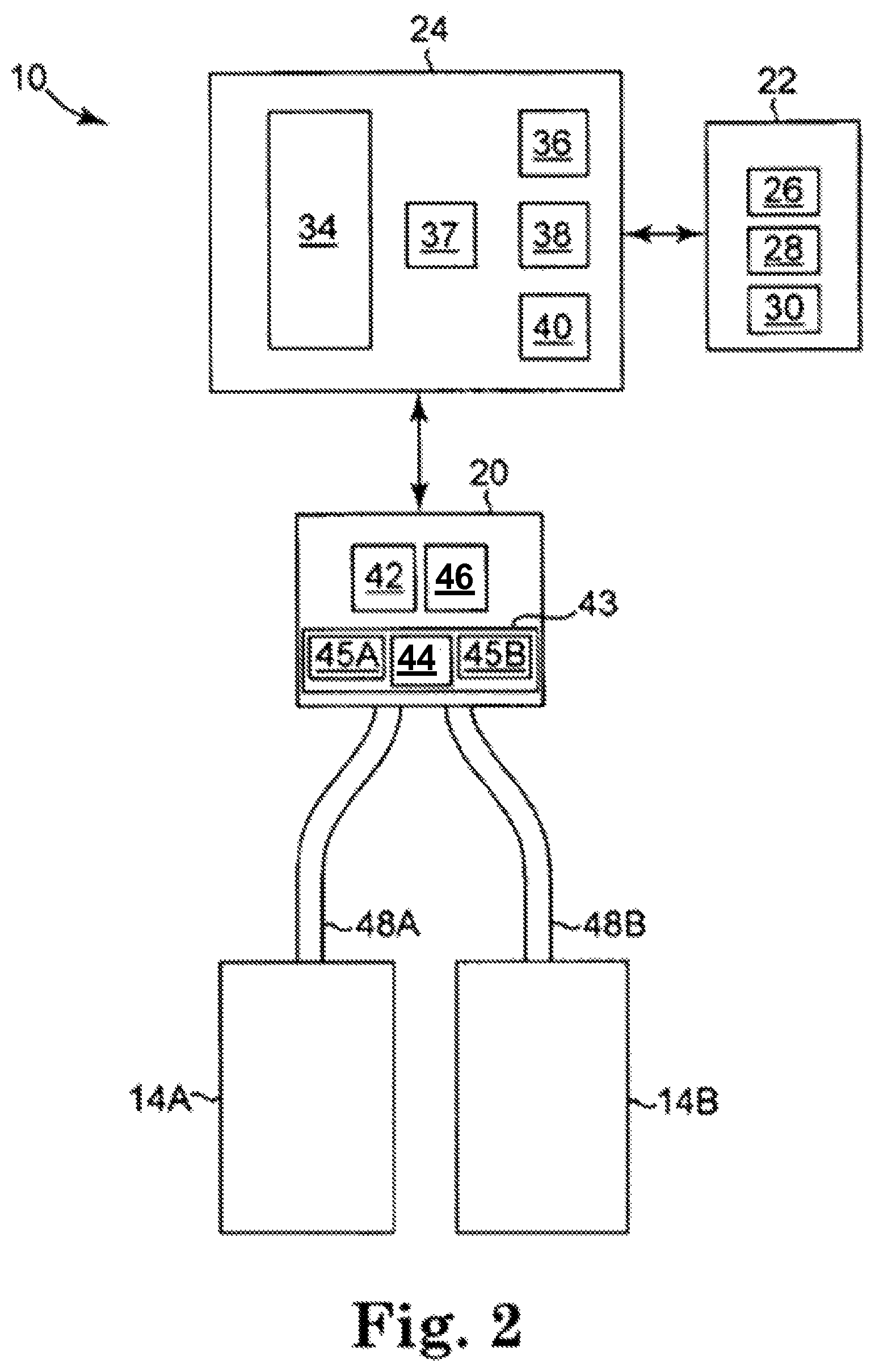
FIG. 1 is a diagrammatic representation of air bed system 10 in an example embodiment. System 10 may include bed 12, which may comprise at least one air chamber 14 surrounded by a resilient border 16 and encapsulated by bed ticking 18. The resilient border 16 may comprise any suitable material, such as foam.
As illustrated in FIG. 1, bed 12 may be a two chamber design having a first air chamber 14A and a second air chamber 14B. First and second air chambers 14A and 14B may be in fluid communication with pump 20. Pump 20 may be in electrical communication with a remote control 22 via control box 24. Remote control 22 may communicate via wired or wireless means with control box 24. Control box 24 may be configured to operate pump 20 to cause increases and decreases in the fluid pressure of first and second air chambers 14A and 14B based upon commands input by a user through remote control 22. Remote control 22 may include display 26, output selecting means 28, pressure increase button 29, and pressure decrease button 30. Output selecting means 28 may allow the user to switch the pump output between the first and second air chambers 14A and 14B, thus enabling control of multiple air chambers with a single remote control 22. For example, output selecting means may by a physical control (e.g., switch or button) or an input control displayed on display 26. Alternatively, separate remote control units may be provided for each air chamber and may each include the ability to control multiple air chambers. Pressure increase and decrease buttons 29 and 30 may allow a user to increase or decrease the pressure, respectively, in the air chamber selected with the output selecting means 28. Adjusting the pressure within the selected air chamber may cause a corresponding adjustment to the firmness of the air chamber.
FIG. 2 is a block diagram detailing data communication between certain components of air bed system 10 according to various examples. As shown in FIG. 2, control box 24 may include power supply 34, processor 36, memory 37, switching means 38, and analog to digital (A/D) converter 40. Switching means 38 may be, for example, a relay or a solid state switch. Switching means 38 may be located in the pump 20 rather than the control box 24.
Pump 20 and remote control 22 may be in two-way communication with the control box 24. Pump 20 may include a motor 42, a pump manifold 43, a relief valve 44, a first control valve 45A, a second control valve 45B, and a pressure transducer 46, and may be fluidly connected with the first air chamber 14A and the second air chamber 14B via a first tube 48A and a second tube 48B, respectively. First and second control valves 45A and 45B may be controlled by switching means 38, and may be operable to regulate the flow of fluid between pump 20 and first and second air chambers 14A and 14B, respectively.
In an example, pump 20 and control box 24 may be provided and packaged as a single unit. Alternatively, pump 20 and control box 24 may be provided as physically separate units.
In operation, power supply 34 may receive power, such as 110 VAC power, from an external source and may convert the power to various forms required by certain components of the air bed system 10. Processor 36 may be used to control various logic sequences associated with operation of the air bed system 10, as will be discussed in further detail below.
The example of the air bed system 10 shown in FIG. 2 contemplates two air chambers 14A and 14B and a single pump 20. However, other examples may include an air bed system having two or more air chambers and one or more pumps incorporated into the air bed system to control the air chambers. In an example, a separate pump may be associated with each air chamber of the air bed system or a pump may be associated with multiple chambers of the air bed system. Separate pumps may allow each air chamber to be inflated or deflated independently and simultaneously. Furthermore, additional pressure transducers may also be incorporated into the air bed system such that, for example, a separate pressure transducer may be associated with each air chamber.
In the event that the processor 36 sends a decrease pressure command to one of air chambers 14A or 14B, switching means 38 may be used to convert the low voltage command signals sent by processor 36 to higher operating voltages sufficient to operate relief valve 44 of pump 20 and open control valves 45A or 45B. Opening relief valve 44 may allow air to escape from air chamber 14A or 14B through the respective air tube 48A or 48B. During deflation, pressure transducer 46 may send pressure readings to processor 36 via the A/D converter 40. The A/D converter 40 may receive analog information from pressure transducer 46 and may convert the analog information to digital information useable by processor 36. Processor 36 may send the digital signal to remote control 22 to update display 26 on the remote control in order to convey the pressure information to the user.
In the event that processor 36 sends an increase pressure command, pump motor 42 may be energized, sending air to the designated air chamber through air tube 48A or 48B via electronically operating corresponding valve 45A or 45B. While air is being delivered to the designated air chamber in order to increase the firmness of the chamber, pressure transducer 46 may sense pressure within pump manifold 43. Again, pressure transducer 46 may send pressure readings to processor 36 via A/D converter 40. Processor 36 may use the information received from A/D converter 40 to determine the difference between the actual pressure in air chamber 14A or 14B and the desired pressure. Processor 36 may send the digital signal to remote control 22 to update display 26 on the remote control in order to convey the pressure information to the user.
Generally speaking, during an inflation or deflation process, the pressure sensed within pump manifold 43 provides an approximation of the pressure within the air chamber. An example method of obtaining a pump manifold pressure reading that is substantially equivalent to the actual pressure within an air chamber is to turn off pump 20, allow the pressure within the air chamber 14A or 14B and pump manifold 43 to equalize, and then sense the pressure within pump manifold 43 with pressure transducer 46. Thus, providing a sufficient amount of time to allow the pressures within pump manifold 43 and chamber 14A or 14B to equalize may result in pressure readings that are accurate approximations of the actual pressure within air chamber 14A or 14B. In various examples, the pressure of 48A/B is continuously monitored using multiple pressure sensors.
In an example, another method of obtaining a pump manifold pressure reading that is substantially equivalent to the actual pressure within an air chamber is through the use of a pressure adjustment algorithm. In general, the method may function by approximating the air chamber pressure based upon a mathematical relationship between the air chamber pressure and the pressure measured within pump manifold 43 (during both an inflation cycle and a deflation cycle), thereby eliminating the need to turn off pump 20 in order to obtain a substantially accurate approximation of the air chamber pressure. As a result, a desired pressure setpoint within air chamber 14A or 14B may be achieved without the need for turning pump 20 off to allow the pressures to equalize. The latter method of approximating an air chamber pressure using mathematical relationships between the air chamber pressure and the pump manifold pressure is described in detail in U.S. application Ser. No. 12/936,084, the entirety of which is incorporated herein by reference.
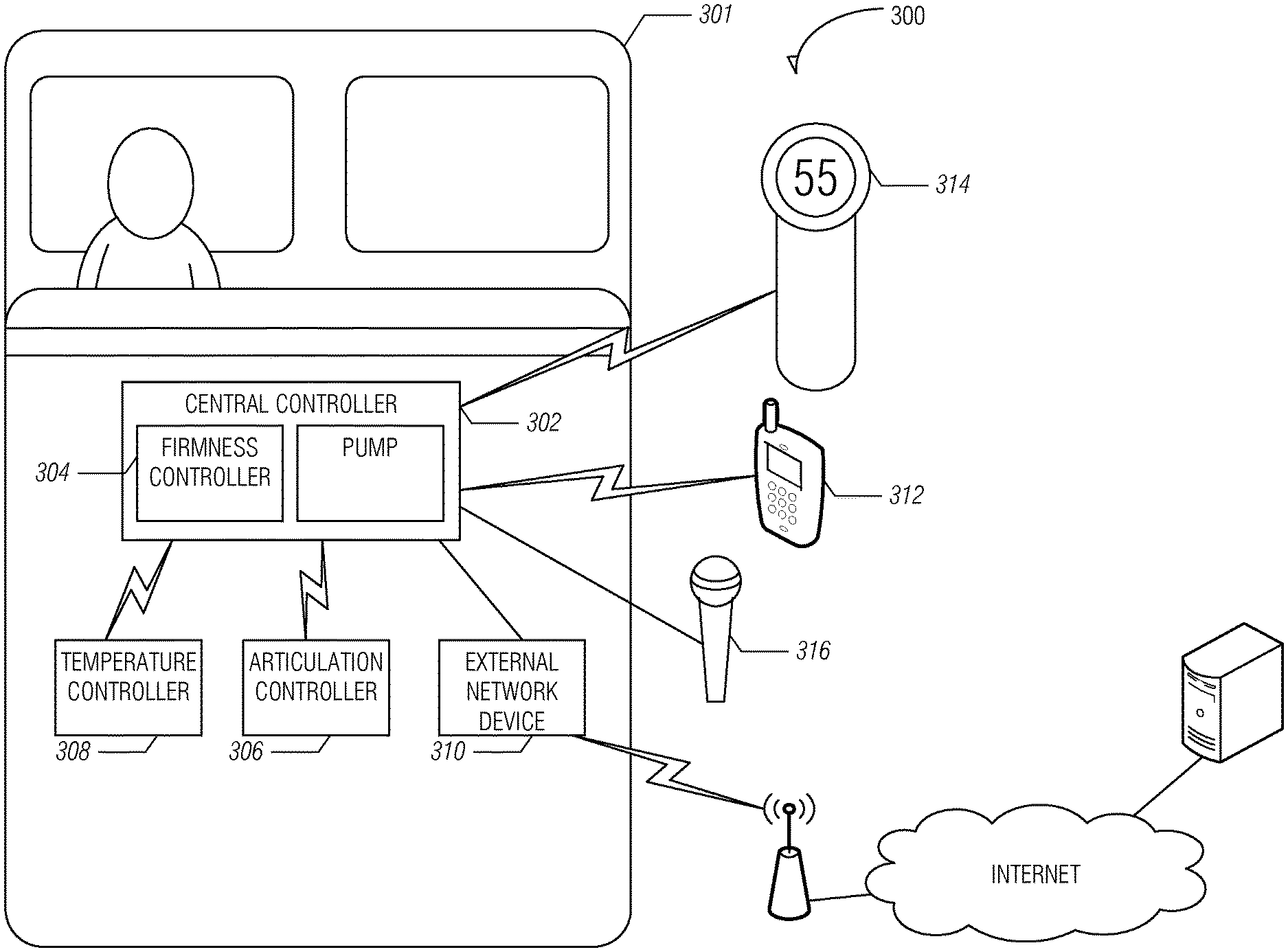
FIG. 3 is illustrates an example air bed system architecture 300. Architecture 300 includes bed 301, central controller 302, firmness controller 304, articulation controller 306, temperature controller 308, external network device 310, remote controllers 312, 314, and voice controller 316. While described as using an air bed, the system architecture may also be used with other types of beds.
As illustrated in FIG. 3, network bed architecture 300 is configured as a star topology with central controller 302 and firmness controller 304 functioning as the hub and articulation controller 306, temperature controller 308, external network device 310, remote controls 312, 314, and voice controller 316 functioning as possible spokes, also referred to herein as components. Thus, in various examples, central controller 302 acts a relay between the various components.
In other examples, different topologies may be used. For example, the components and central controller 302 may be configured as a mesh network in which each component may communicate with one or all of the other components directly, bypassing central controller 302. In various examples, a combination of topologies may be used. For example, remote controller 312 may communicate directly to temperature controller 308 but also relay the communication to central controller 302.
In yet another example, central controller 302 listens to communications (e.g., control signals) between components even if the communication is not being relayed through central controller 302. For example, consider a user sending a command using remote 312 to temperature controller 308. Central controller 302 may listen for the command and check to determine if instructions are stored at central controller 302 to override the command (e.g., it conflicts with a previous setting). Central controller 302 may also log the command for future use (e.g., determining a pattern of user preferences for the components).
In various examples, the controllers and devices illustrated in FIG. 3 may each include a processor, a storage device, and a network interface. The processor may be a general purpose central processing unit (CPU) or application-specific integrated circuit (ASIC). The storage device may include volatile or non-volatile static storage (e.g., Flash memory, RAM, EPROM, etc.). The storage device may store instructions which, when executed by the processor, configure the processor to perform the functionality described herein. For example, a processor of firmness control 304 may be configured to send a command to a relief valve to decrease the pressure in a bed.
In various examples, the network interface of the components may be configured to transmit and receive communications in a variety of wired and wireless protocols. For example, the network interface may be configured to use the 802.11 standards (e.g., 802.11a/b/c/g/n/ac), PAN network standards such as 802.15.4 or Bluetooth, infrared, cellular standards (e.g., 3G/4G etc.), Ethernet, and USB for receiving and transmitting data. The previous list is not intended to exhaustive and other protocols may be used. Not all components of FIG. 3 need to be configured to use the same protocols. For example, remote control 312 may communicate with central controller 302 via Bluetooth while temperature controller 308 and articulation controller 306 are connected to central controller using 802.15.4. Within FIG. 3, the lightning connectors represent wireless connections and the solid lines represent wired connections, however, the connections between the components is not limited to such connections and each connection may be wired or wireless.
Moreover, in various examples, the processor, storage device, and network interface of a component may be located in different locations than various elements used to effect a command. For example, as in FIG. 1, firmness controller 302 may have a pump that is housed in a separate enclosure than the processor used to control the pump. Similar separation of elements may be employed for the other controllers and devices in FIG. 3.
In various examples, firmness controller 304 is configured to regulate pressure in an air mattress. For example, firmness controller 304 may include a pump such as described with reference to FIG. 2 (see e.g., pump 20). Thus, in an example, firmness controller 304 may respond to commands to increase or decrease pressure in the air mattress. The commands may be received from another component or based on stored application instruction that are part of firmness controller 304.
As illustrated in FIG. 3 central controller 302 includes firmness controller 304. Thus, in an example, the processor of central controller 302 and firmness control 304 may be the same processor. Furthermore, the pump may also be part of central controller 302. Accordingly, central controller 302 may be responsible for pressure regulation as well as other functionality as described in further portions of this disclosure.
In various examples, articulation controller 306 is configured to adjust the position of a bed (e.g., bed 301) by adjusting the foundation that supports the bed. In an example, separate positions may be set for two different beds (e.g., two twin beds placed next to each other). The foundation may include more than one zone that may be independently adjusted. Articulation control 306 may also be configured to provide different levels of massage to a person on the bed.
In various examples, temperature controller 308 is configured to increase, decrease, or maintain the temperature of a user. For example, a pad may be placed on top of or be part of the air mattress. Air may be pushed through the pad and vented to cool off a user of the bed. Conversely, the pad may include a heating element that may be used to keep the user warm. In various examples, temperature controller 308 receives temperature readings from the pad.
In various examples, additional controllers may communicate with central controller 302. These controllers may include, but are not limited to, illumination controllers for turning on and off light elements placed on and around the bed and outlet controllers for controlling power to one or more power outlets.
In various examples, external network device 310, remote controllers 312, 314 and voice controller 316 may be used to input commands (e.g., from a user or remote system) to control one or more components of architecture 300. The commands may be transmitted from one of the controllers 312, 314, or 316 and received in central controller 302. Central controller 302 may process the command to determine the appropriate component to route the received command. For example, each command sent via one of controllers 312, 314, or 316 may include a header or other metadata that indicates which component the command is for. Central controller 302 may then transmit the command via central controller 302's network interface to the appropriate component.
For example, a user may input a desired temperature for the user's bed into remote control 312. The desired temperature may be encapsulated in a command data structure that includes the temperature as well as identifies temperature controller 308 as the desired component to be controlled. The command data structure may then be transmitted via Bluetooth to central controller 302. In various examples, the command data structure is encrypted before being transmitted. Central controller 302 may parse the command data structure and relay the command to temperature controller 308 using a PAN. Temperature controller 308 may be then configure its elements to increase or decrease the temperature of the pad depending on the temperature originally input into remote control 312.
In various examples, data may be transmitted from a component back to one or more of the remote controls. For example, the current temperature as determined by a sensor element of temperature controller 308, the pressure of the bed, the current position of the foundation or other information may be transmitted to central controller 302. Central controller 302 may then transmit the received information and transmit it to remote control 312 where it may be displayed to the user.
In various examples, multiple types of devices may be used to input commands to control the components of architecture 300. For example, remote control 312 may be a mobile device such as a smart phone or tablet computer running an application. Other examples of remote control 312 may include a dedicated device for interacting with the components described herein. In various examples, remote controls 312/314 include a display device for displaying an interface to a user. Remote control 312/314 may also include one or more input devices. Input devices may include, but are not limited to, keypads, touchscreen, gesture, motion and voice controls.
Remote control 314 may be a single component remote configured to interact with one component of the mattress architecture. For example, remote control 314 may be configured to accept inputs to increase or decrease the air mattress pressure. Voice controller 316 may be configured to accept voice commands to control one or more components. In various examples, more than one of the remote controls 312/314 and voice controller 316 may be used.
With respect to remote control 312, the application may be configured to pair with one or more central controllers. For each central controller, data may be transmitted to the mobile device that includes a list of components linked with the central controller. For example, consider that remote control 312 is a mobile phone and that the application has been authenticated and paired with central controller 302. Remote control 312 may transmit a discovery request to central controller 302 to inquiry about other components and available services. In response, central controller 302 may transmit a list of services that includes available functions for adjusting the firmness of the bed, position of the bed, and temperature of the bed. In various embodiments, the application may then display functions for increasing/decreasing pressure of the air mattress, adjusting positions of the bed, and adjusting temperature. If components are added/removed to the architecture under control of central controller 302, an updated list may be transmitted to remote control 312 and the interface of the application may be adjusted accordingly.
In various examples, central controller 302 is configured to analyze data collected by a pressure transducer (e.g., transducer 46 with respect to FIG. 2) to determine various states of a person lying on the bed. For example, central controller 302 may determine the heart rate or respiration rate of a person lying in the bed. Additional processing may be done using the collected data to determine a possible sleep state of the person. For example, central controller 302 may determine when a person falls asleep and, while asleep, the various sleep states of the person.
In various examples, external network device 310 includes a network interface to interact with an external server for processing and storage of data related to components in architecture 300. For example, the determined sleep data as described above may be transmitted via a network (e.g., the Internet) from central controller 302 to external network device 310 for storage. In an example, the pressure transducer data may be transmitted to the external server for additional analysis. The external network device 310 may also analyze and filter the data before transmitting it to the external server.
In an example, diagnostic data of the components may also be routed to external network device 310 for storage and diagnosis on the external server. For example, if temperature controller 308 detects an abnormal temperature reading (e.g., a drop in temperature over one minute that exceeds a set threshold) diagnostic data (sensor readings, current settings, etc.) may be wireless transmitted from temperature controller 308 to central controller 302. Central controller 302 may then transmit this data via USB to external network device 310. External device 310 may wirelessly transmit the information to an WLAN access point where it is routed to the external server for analysis.
Example Machine Architecture and Machine-Readable Medium
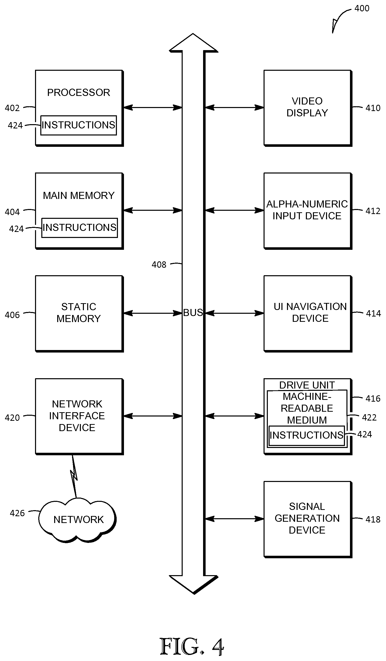
FIG. 4 is a block diagram of machine in the example form of a computer system 400 within which instructions, for causing the machine to perform any one or more of the methodologies discussed herein, may be executed. In alternative embodiments, the machine operates as a standalone device or may be connected (e.g., networked) to other machines. In a networked deployment, the machine may operate in the capacity of a server or a client machine in server-client network environment, or as a peer machine in a peer-to-peer (or distributed) network environment. The machine may be a personal computer (PC), a tablet PC, a set-top box (STB), a Personal Digital Assistant (PDA), a cellular telephone, a web appliance, a network router, switch or bridge, or any machine capable of executing instructions (sequential or otherwise) that specify actions to be taken by that machine. Further, while only a single machine is illustrated, the term "machine" shall also be taken to include any collection of machines that individually or jointly execute a set (or multiple sets) of instructions to perform any one or more of the methodologies discussed herein.
The example computer system 400 includes a processor 402 (e.g., a central processing unit (CPU), a graphics processing unit (GPU), ASIC or a combination), a main memory 404 and a static memory 406, which communicate with each other via a bus 408. The computer system 400 may further include a video display unit 410 (e.g., a liquid crystal display (LCD) or a cathode ray tube (CRT)). The computer system 400 also includes an alphanumeric input device 412 (e.g., a keyboard, touchscreen), a user interface (UI) navigation device 414 (e.g., a mouse), a disk drive unit 416, a signal generation device 418 (e.g., a speaker) and a network interface device 420.
Machine-Readable Medium
The disk drive unit 416 includes a machine-readable medium 422 on which is stored one or more sets of instructions and data structures (e.g., software) 424 embodying or utilized by any one or more of the methodologies or functions described herein. The instructions 424 may also reside, completely or at least partially, within the main memory 404 and/or within the processor 402 during execution thereof by the computer system 400, the main memory 404 and the processor 402 also constituting machine-readable media.
While the machine-readable medium 422 is shown in an example embodiment to be a single medium, the term "machine-readable medium" may include a single medium or multiple media (e.g., a centralized or distributed database, and/or associated caches and servers) that store the one or more instructions or data structures. The term "machine-readable medium" shall also be taken to include any tangible medium that is capable of storing, encoding or carrying instructions for execution by the machine and that cause the machine to perform any one or more of the methodologies of the present invention, or that is capable of storing, encoding or carrying data structures utilized by or associated with such instructions. The term "machine-readable medium" shall accordingly be taken to include, but not be limited to, solid-state memories, and optical and magnetic media. Specific examples of machine-readable media include non-volatile memory, including by way of example semiconductor memory devices, e.g., Erasable Programmable Read-Only Memory (EPROM), Electrically Erasable Programmable Read-Only Memory (EEPROM), and flash memory devices; magnetic disks such as internal hard disks and removable disks; magneto-optical disks; and CD-ROM and DVD-ROM disks.
Transmission Medium
The instructions 424 may further be transmitted or received over a communications network 426 using a transmission medium. The instructions 424 may be transmitted using the network interface device 420 and any one of a number of well-known transfer protocols (e.g., HTTP). Examples of communication networks include a local area network ("LAN"), a wide area network ("WAN"), the Internet, mobile telephone networks, Plain Old Telephone (POTS) networks, and wireless data networks (e.g., WiFi and WiMax networks). The term "transmission medium" shall be taken to include any intangible medium that is capable of storing, encoding or carrying instructions for execution by the machine, and includes digital or analog communications signals or other intangible media to facilitate communication of such software.
Although an embodiment has been described with reference to specific example embodiments, it will be evident that various modifications and changes may be made to these embodiments without departing from the broader spirit and scope of the invention. Accordingly, the specification and drawings are to be regarded in an illustrative rather than a restrictive sense. The accompanying drawings that form a part hereof, show by way of illustration, and not of limitation, specific embodiments in which the subject matter may be practiced. The embodiments illustrated are described in sufficient detail to enable those skilled in the art to practice the teachings disclosed herein. Other embodiments may be utilized and derived therefrom, such that structural and logical substitutions and changes may be made without departing from the scope of this disclosure. This Detailed Description, therefore, is not to be taken in a limiting sense, and the scope of various embodiments is defined only by the appended claims, along with the full range of equivalents to which such claims are entitled. As it common, the terms "a" and "an" may refer to one or more unless otherwise indicated.
* * * * *
D00000
D00001
D00002
D00003
D00004
XML
uspto.report is an independent third-party trademark research tool that is not affiliated, endorsed, or sponsored by the United States Patent and Trademark Office (USPTO) or any other governmental organization. The information provided by uspto.report is based on publicly available data at the time of writing and is intended for informational purposes only.
While we strive to provide accurate and up-to-date information, we do not guarantee the accuracy, completeness, reliability, or suitability of the information displayed on this site. The use of this site is at your own risk. Any reliance you place on such information is therefore strictly at your own risk.
All official trademark data, including owner information, should be verified by visiting the official USPTO website at www.uspto.gov. This site is not intended to replace professional legal advice and should not be used as a substitute for consulting with a legal professional who is knowledgeable about trademark law.