Rotational style tool bit assembly
Taitt , et al. December 29, 2
U.S. patent number 10,876,401 [Application Number 15/649,895] was granted by the patent office on 2020-12-29 for rotational style tool bit assembly. This patent grant is currently assigned to The Sollami Company. The grantee listed for this patent is Phillip Sollami, Ronnie R. Taitt. Invention is credited to Phillip Sollami, Ronnie R. Taitt.


| United States Patent | 10,876,401 |
| Taitt , et al. | December 29, 2020 |
Rotational style tool bit assembly
Abstract
A bit assembly includes a base block and a bit holder having a forward body portion and a generally cylindrical shank. The forward body portion includes a plurality of vanes that define a plurality of cavities or flutes configured to carry removable size pieces from a trenched area to the adjacent surface alongside a trenching machine. The spaced cavities are supported by the vertical vanes that also aid in removing the loosened material. The shank of the bit holder includes an annular groove configured to receive a bit retainer once the bit holder is inserted into a bore of a base block.
| Inventors: | Taitt; Ronnie R. (Herrin, IL), Sollami; Phillip (Herrin, IL) | ||||||||||
|---|---|---|---|---|---|---|---|---|---|---|---|
| Applicant: |
|
||||||||||
| Assignee: | The Sollami Company (Herrin,
IL) |
||||||||||
| Family ID: | 1000002754122 | ||||||||||
| Appl. No.: | 15/649,895 | ||||||||||
| Filed: | July 14, 2017 |
Related U.S. Patent Documents
| Application Number | Filing Date | Patent Number | Issue Date | ||
|---|---|---|---|---|---|
| 62366779 | Jul 26, 2016 | ||||
| Current U.S. Class: | 1/1 |
| Current CPC Class: | E21C 35/197 (20130101); E21C 35/1831 (20200501); E21C 35/18 (20130101); B25B 21/02 (20130101); B25B 15/005 (20130101); B25B 23/108 (20130101); B25B 15/00 (20130101); B25B 21/00 (20130101); B25B 23/00 (20130101) |
| Current International Class: | E21C 35/18 (20060101); E21C 35/183 (20060101); E21C 35/197 (20060101); B25B 23/00 (20060101); B25B 21/02 (20060101); B25B 23/10 (20060101); B25B 21/00 (20060101); B25B 15/00 (20060101) |
| Field of Search: | ;299/106,107,110,111 |
References Cited [Referenced By]
U.S. Patent Documents
| 3342532 | September 1967 | Krekeler |
| 3397012 | August 1968 | Krekeler |
| 3476438 | November 1969 | Bower, Jr. |
| 3519309 | July 1970 | Engle |
| 3833264 | September 1974 | Elders |
| 3833265 | September 1974 | Elders |
| 3865437 | February 1975 | Crosby |
| 4065185 | December 1977 | Elders |
| 4084856 | April 1978 | Emmerich |
| 4247150 | January 1981 | Wrulich et al. |
| RE30807 | December 1981 | Elders |
| 4310939 | January 1982 | Iijima |
| 4453775 | June 1984 | Clemmow |
| 4478298 | October 1984 | Hake |
| 4489986 | December 1984 | Dziak |
| 4525178 | June 1985 | Hall |
| 4561698 | December 1985 | Beebe |
| 4570726 | February 1986 | Hall |
| 4604106 | August 1986 | Hall |
| 4694918 | September 1987 | Hall |
| 4702525 | October 1987 | Sollami |
| 4711504 | December 1987 | Berchem |
| 4763956 | August 1988 | Emmerich |
| 4811801 | March 1989 | Salesky |
| 4818027 | April 1989 | Simon |
| 4844550 | July 1989 | Beebe |
| 4915455 | April 1990 | O'Neill |
| 4944559 | July 1990 | Sionett |
| 5067775 | November 1991 | D'Angelo |
| 5088797 | February 1992 | O'Neill |
| 5098167 | March 1992 | Latham |
| 5159233 | October 1992 | Sponseller |
| 5161627 | November 1992 | Burkett |
| 5273343 | December 1993 | Ojanen |
| 5287937 | February 1994 | Sollami |
| 5302005 | April 1994 | O'Neill |
| 5303984 | April 1994 | Ojanen |
| 5352079 | October 1994 | Croskey |
| 5370448 | December 1994 | Sterwerf, Jr. |
| 5374111 | December 1994 | Den Besten |
| 5415462 | May 1995 | Massa |
| 5417475 | May 1995 | Graham |
| 5458210 | October 1995 | Sollami |
| 5492188 | February 1996 | Smith et al. |
| 5551760 | September 1996 | Sollami |
| 5607206 | March 1997 | Siddle |
| 5628549 | May 1997 | Ritchey |
| 5725283 | March 1998 | O'Neill |
| 5823632 | October 1998 | Burkett |
| 5924501 | July 1999 | Tibbitts |
| 5931542 | August 1999 | Britzke |
| 5992405 | November 1999 | Sollami |
| D420013 | February 2000 | Warren |
| 6019434 | February 2000 | Emmerich |
| 6102486 | August 2000 | Briese |
| 6176552 | January 2001 | Topka, Jr. |
| 6196340 | March 2001 | Jensen et al. |
| 6199451 | March 2001 | Sollami |
| 6250535 | June 2001 | Sollami |
| 6331035 | December 2001 | Montgomery, Jr. |
| 6341823 | January 2002 | Sollami |
| 6354771 | March 2002 | Bauschulte |
| 6357832 | March 2002 | Sollami |
| 6371567 | April 2002 | Sollami |
| 6508516 | January 2003 | Kammerer |
| D471211 | March 2003 | Sollami |
| 6585326 | July 2003 | Sollami |
| 6685273 | February 2004 | Sollami |
| 6692083 | February 2004 | Latham |
| D488170 | April 2004 | Sollami |
| 6733087 | May 2004 | Hall |
| 6739327 | May 2004 | Sollami |
| 6786557 | September 2004 | Montgomery |
| 6824225 | November 2004 | Stiffler |
| 6846045 | January 2005 | Sollami |
| 6854810 | February 2005 | Montgomery |
| 6866343 | March 2005 | Holl et al. |
| 6968912 | November 2005 | Sollami |
| 6981496 | January 2006 | Szendrovari |
| 6994404 | February 2006 | Sollami |
| 7097258 | August 2006 | Sollami |
| 7118181 | October 2006 | Frear |
| 7150505 | December 2006 | Sollami |
| 7195321 | March 2007 | Sollami |
| 7210744 | May 2007 | Montgomery |
| 7229136 | June 2007 | Sollami |
| 7234782 | June 2007 | Stehney |
| D554162 | October 2007 | Hall |
| 7320505 | January 2008 | Hall |
| 7338135 | March 2008 | Hall |
| 7347292 | March 2008 | Hall |
| D566137 | April 2008 | Hall |
| 7353893 | April 2008 | Hall |
| 7384105 | June 2008 | Hall |
| 7396086 | June 2008 | Hall |
| 7401862 | July 2008 | Holl et al. |
| 7401863 | July 2008 | Hall |
| 7410221 | August 2008 | Hall |
| 7413256 | August 2008 | Hall |
| 7413258 | August 2008 | Hall |
| 7419224 | September 2008 | Hall |
| 7445294 | November 2008 | Hall |
| D581952 | December 2008 | Hall |
| 7464993 | December 2008 | Hall |
| 7469756 | December 2008 | Hall |
| 7469971 | December 2008 | Hall |
| 7469972 | December 2008 | Hall |
| 7475948 | January 2009 | Hall |
| 7523794 | April 2009 | Hall |
| 7568770 | August 2009 | Hall |
| 7569249 | August 2009 | Hall |
| 7571782 | August 2009 | Hall |
| 7575425 | August 2009 | Hall |
| 7588102 | September 2009 | Hall |
| 7594703 | September 2009 | Hall |
| 7600544 | October 2009 | Sollami |
| 7600823 | October 2009 | Hall |
| 7628233 | December 2009 | Hall |
| 7635168 | December 2009 | Hall |
| 7637574 | December 2009 | Hall |
| 7648210 | January 2010 | Hall |
| 7665552 | February 2010 | Hall |
| 7669938 | March 2010 | Hall |
| 7681338 | March 2010 | Hall |
| 7712693 | May 2010 | Hall |
| 7717365 | May 2010 | Hall |
| 7722127 | May 2010 | Hall |
| 7789468 | September 2010 | Sollami |
| 7832808 | November 2010 | Hall |
| 7883155 | February 2011 | Sollami |
| 7950745 | May 2011 | Sollami |
| 7963617 | June 2011 | Hall |
| 3007049 | August 2011 | Fader |
| 7992944 | August 2011 | Hall |
| 7992945 | August 2011 | Hall |
| 7997661 | August 2011 | Hall |
| 8007051 | August 2011 | Hall |
| 8029068 | October 2011 | Hall |
| 8033615 | October 2011 | Hall |
| 8033616 | October 2011 | Hall |
| 8038223 | October 2011 | Hall |
| 8061784 | November 2011 | Hall |
| 8109349 | February 2012 | Hall |
| 8118371 | February 2012 | Hall |
| 8136887 | March 2012 | Hall |
| 8201892 | June 2012 | Hall |
| 8215420 | July 2012 | Hall |
| 8292372 | October 2012 | Hall |
| 8414085 | April 2013 | Hall |
| 8449039 | May 2013 | Hall |
| 8485609 | July 2013 | Hall |
| 8500209 | August 2013 | Hall |
| 8540320 | September 2013 | Sollami |
| RE44690 | January 2014 | Sollami |
| 8622482 | January 2014 | Sollami |
| 8622483 | January 2014 | Sollami |
| 8646848 | February 2014 | Hall |
| 8728382 | May 2014 | Hall |
| 9004610 | April 2015 | Erdmann et al. |
| 9028008 | May 2015 | Bookhamer |
| 9039099 | May 2015 | Sollami |
| 9316061 | April 2016 | Hall |
| 9518464 | December 2016 | Sollami |
| 9909416 | March 2018 | Sollami |
| 9976418 | May 2018 | Sollami |
| 9988903 | June 2018 | Sollami |
| 10072501 | September 2018 | Sollami |
| 10105870 | October 2018 | Sollami |
| 10107097 | October 2018 | Sollami |
| 10107098 | October 2018 | Sollami |
| 10180065 | January 2019 | Sollami |
| 10260342 | April 2019 | Sollami |
| 10323515 | June 2019 | Sollami |
| 10337324 | July 2019 | Sollami |
| 10370966 | August 2019 | Sollami |
| 10385689 | August 2019 | Sollami |
| 10415386 | September 2019 | Sollami |
| 10502056 | December 2019 | Sollami |
| 2002/0167216 | November 2002 | Sollami |
| 2003/0015907 | January 2003 | Sollami |
| 2003/0047985 | March 2003 | Stiffler |
| 2003/0209366 | November 2003 | McAlvain |
| 2004/0004389 | January 2004 | Latham |
| 2004/0174065 | September 2004 | Sollami |
| 2006/0071538 | April 2006 | Sollami |
| 2006/0186724 | August 2006 | Stehney |
| 2006/0261663 | November 2006 | Sollami |
| 2008/0035386 | February 2008 | Hall et al. |
| 2008/0036283 | February 2008 | Hall et al. |
| 2008/0145686 | June 2008 | Mirchandani |
| 2008/0284234 | November 2008 | Hall et al. |
| 2009/0256413 | October 2009 | Majagi |
| 2009/0261646 | October 2009 | Ritchie et al. |
| 2010/0244545 | September 2010 | Hall |
| 2010/0253130 | October 2010 | Sollami |
| 2010/0320003 | December 2010 | Sollami |
| 2011/0006588 | January 2011 | Monyak et al. |
| 2011/0089747 | April 2011 | Helsel |
| 2011/0204703 | August 2011 | Sollami |
| 2011/0241409 | October 2011 | Swope |
| 2011/0254350 | October 2011 | Hall |
| 2012/0027514 | February 2012 | Hall |
| 2012/0068527 | March 2012 | Erdmann |
| 2012/0104830 | May 2012 | Monyak |
| 2012/0181845 | July 2012 | Sollami |
| 2012/0248663 | October 2012 | Hall |
| 2012/0261977 | October 2012 | Hall |
| 2012/0280559 | November 2012 | Watson |
| 2012/0286559 | November 2012 | Sollami |
| 2012/0319454 | December 2012 | Swope |
| 2013/0002004 | January 2013 | Greenspan |
| 2013/0169023 | July 2013 | Monyak |
| 2014/0326516 | November 2014 | Haugvaldstad |
| 2015/0028656 | January 2015 | Sollami |
| 2015/0035343 | February 2015 | Ojanen |
| 2015/0137579 | May 2015 | Lachmann et al. |
| 2015/0198040 | July 2015 | Voitic et al. |
| 2015/0240634 | August 2015 | Sollami |
| 2015/0285074 | October 2015 | Sollami |
| 2015/0292325 | October 2015 | Sollami |
| 2015/0300166 | October 2015 | Ries et al. |
| 2015/0308488 | October 2015 | Kahl |
| 2015/0315910 | November 2015 | Sollami |
| 2015/0354285 | December 2015 | Hall |
| 2016/0194956 | July 2016 | Sollami |
| 2016/0229084 | August 2016 | Lehnert |
| 2017/0089198 | March 2017 | Sollami |
| 102004049710 | Apr 2006 | DE | |||
| 102011079115 | Jan 2013 | DE | |||
| 202012100353 | Jun 2013 | DE | |||
| 102015121953 | Jul 2016 | DE | |||
| 102016118658 | Mar 2017 | DE | |||
| 3214261 | Sep 2017 | EP | |||
| 1114156 | May 1968 | GB | |||
| 2483157 | Feb 2012 | GB | |||
| 2534370 | Jul 2016 | GB | |||
| 2008105915 | Sep 2008 | WO | |||
| 2008105915 | Sep 2008 | WO | |||
| 2009006612 | Jan 2009 | WO | |||
Assistant Examiner: Goodwin; Michael A
Attorney, Agent or Firm: O'Connor; Mercedes V. Rockman Videbeck & O'Connor
Parent Case Text
CROSS-REFERENCE TO RELATED APPLICATION(S)
This application claims priority to U.S. Provisional Application No. 62/366,779, filed Jul. 26, 2016, to the extent allowed by law and the contents of which are incorporated herein by reference in their entireties.
Claims
What is claimed is:
1. A bit holder comprising: a forward body portion comprising a plurality of vanes axially and radially extending from a top surface of the body portion to a circumference of a generally cylindrical tire portion of the body portion, each vane of the plurality of vanes comprising a concave outer surface adjacent the top surface of the body portion, a convex outer surface adjacent the concave outer surface, and a laterally extending outer surface adjacent the convex outer surface; a plurality of arcuate cavities, each arcuate cavity of the plurality of arcuate cavities comprising an entirely continuous radially concave surface extending laterally between two vanes of the plurality of vanes; and a generally cylindrical shank depending axially from the forward body portion, the shank comprising an annular groove adjacent a distal end of the shank.
2. The bit holder of claim 1, wherein each arcuate cavity of the plurality of arcuate cavities axially extends from adjacent the top surface to adjacent the tire portion.
3. The bit holder of claim 1, wherein each arcuate cavity is defined by a first outer edge of a first vane, a second outer edge of a second vane adjacent to the first vane, and an upper edge of the tire portion.
4. The bit holder of claim 1, wherein the plurality of cavities and the plurality of vanes are adapted to direct and move material from a terra firma to a surface adjacent a trenching machine.
5. The bit holder of claim 1, further comprising: a generally cylindrical bore disposed in the top surface, the bore axially and centrally positioned in the bit holder.
6. The bit holder of claim 5, further comprising: an insert centrally positioned within the bore of the top surface, the insert adapted to be brazed in the bore of the top surface.
7. The bit holder of claim 1, wherein the body portion extends axially and radially outwardly from the top surface to the tire portion.
8. The bit holder of claim 1, further comprising: a chamfer extending from the tire portion to a rear flange of the body portion.
9. The bit holder of claim 1, further comprising: a decreased diameter tapered distal portion adjacent the tire portion, the distal portion axially extending to the shank.
10. The bit holder of claim 1, wherein the plurality of vanes converge proximate an axis of rotation on the top surface of the bit holder and diverge radially towards the tire portion.
11. The bit holder of claim 1, wherein the shank comprises: a generally cylindrical increased diameter first segment subjacent the body portion; a generally cylindrical decreased diameter second segment subjacent to the first segment; and a shoulder disposed between the first segment and the second segment, the second segment axially extending from the shoulder to a tapered distal segment that axially extends to the distal end of the shank.
12. The bit holder of claim 11, wherein the second segment comprises the annular groove adjacent the distal end of the shank.
13. The bit holder of claim 1, further comprising: a retainer adapted to slidably engage the annular grove of the shank and adapted to maintain the bit holder within a bore of a base block, the annular groove of the shank extending beyond a rearward face of the base block.
14. The bit holder of claim 13, wherein the retainer comprises an outer diameter larger than a diameter of the shank.
15. The bit holder of claim 13, wherein the retainer comprises an inner diameter that is at least a diameter of the annular groove.
16. The bit holder of claim 13, wherein the retainer comprises a pair of arcuate legs disposed on opposite side of an arcuate portion, the arcuate portion defining a radially expandable area.
17. The bit holder of claim 16, wherein the arcuate portion is adapted to engage a complementary shaped portion of the annular groove.
18. The bit holder of claim 13, wherein the retainer comprises a thickness that is less than an axial length of the annular groove of the shank.
19. The bit holder of claim 1, wherein the annular groove comprises one of an arcuate inner surface and a flat inner surface.
20. A bit holder comprising: a forward body portion comprising at least one vane axially and radially extending from a top surface of the body portion to a circumference of a generally cylindrical tire portion of the body portion, the at least one vane comprising a concave outer surface adjacent the top surface of the body portion, a convex outer surface adjacent the concave outer surface, and a laterally extending outer surface adjacent the convex outer surface; at least one arcuate cavity comprising a continuous radially concave surface extending laterally between outer edges of the at least one vane; and a generally cylindrical shank depending axially from the forward body portion, the shank comprising an annular groove adjacent a distal end of the shank.
Description
TECHNICAL FIELD
This disclosure relates to bit assemblies for road milling, mining, and trenching equipment.
BACKGROUND
Road milling, mining, and trenching equipment utilizes bits or inserts traditionally set in a bit assembly having a bit holder and a bit holder block. The insert is retained within the bit holder which is retained within a bore in the bit holder block. A plurality of the bit assemblies are mounted on the outside of a rotatable drum, typically in a V-shaped or spiral configuration, or the plates are mounted to a chain driven boom or a wheel trencher. The combinations of bit assemblies have been utilized to remove material from the terra firma, such as degrading the surface of the earth, minerals, cement, concrete, macadam or asphalt pavement. Individual bits, bit holders, and bit holder blocks may wear down or break over time due to the harsh cutting environment. In various trenching cutting conditions, a hardened insert, such as a tungsten carbide insert, is used to initially impact the surface material and break it down into smaller removable pieces which are then carried outside the trenched area to the adjacent surface alongside the trenching machine. The bit assembly of the present disclosure uses a hardened insert in combination with a bit holder having vertical vanes configured to aid in removing the loosened material, assist in the rotation of the tool, and allow the profile at the forward end of the tool to wear symmetrically.
SUMMARY
This disclosure relates generally to bit assemblies for road milling, mining, and trenching equipment. One implementation of the teachings herein is a bit holder that includes a forward body portion comprising a plurality of vanes axially and radially extending from a top surface of the body portion to a generally cylindrical tire portion of the body portion; and a generally cylindrical shank depending axially from the forward body portion, the shank comprising an annular groove adjacent a distal end of the shank.
In another implementation of the teachings herein is a bit holder that includes a forward body portion comprising at least one vane axially and radially extending from a top surface of the body portion to a generally cylindrical tire portion of the body portion; and a generally cylindrical shank depending axially from the forward body portion, the shank comprising an annular groove adjacent a distal end of the shank.
These and other aspects of the present disclosure are disclosed in the following detailed description of the embodiments, the appended claims and the accompanying figures.
BRIEF DESCRIPTION OF THE DRAWINGS
The various features, advantages, and other uses of the apparatus will become more apparent by referring to the following detailed description and drawings, wherein like reference numerals refer to like parts throughout the several views. It is emphasized that, according to common practice, the various features of the drawings are not to-scale. On the contrary, the dimensions of the various features are arbitrarily expanded or reduced for clarity.
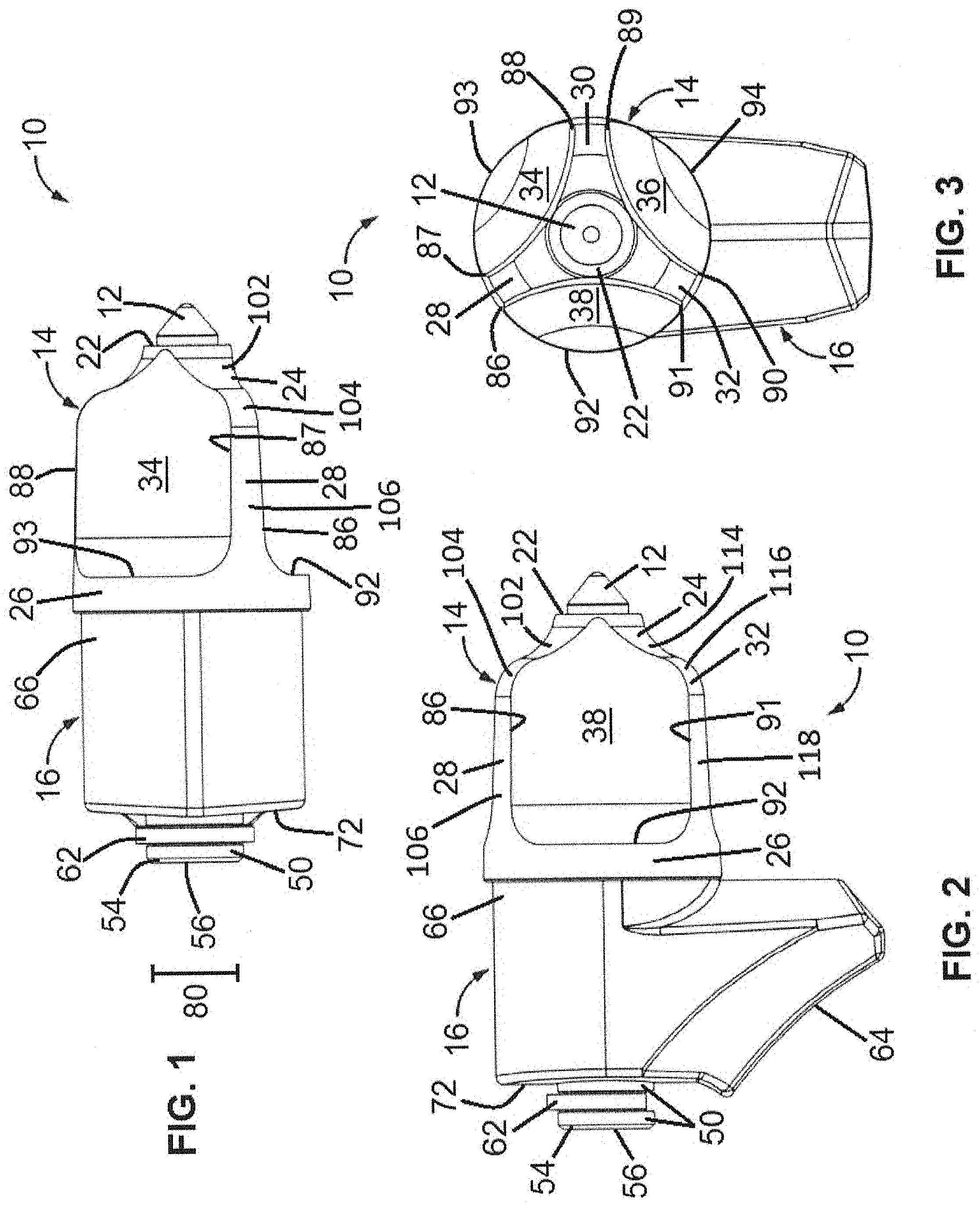
FIG. 1 is a top elevation view of an embodiment of a bit assembly;
FIG. 2 is a right side elevation view of the embodiment of the bit assembly of FIG. 1;
FIG. 3 is a front elevation view of the embodiment of the bit assembly of FIG. 1;
FIG. 4 is a right side perspective view of the embodiment of the bit assembly of FIG. 1;
FIG. 5 is a left side perspective view of the embodiment of the bit assembly of FIG. 1;
FIG. 6 is an exploded side elevation view of the embodiment of the bit assembly of FIG. 1;
FIG. 6A is an exploded side elevation view of the embodiment of the bit assembly of FIG. 1; and
FIG. 7 is an exploded perspective view of the embodiment of the bit assembly of FIG. 1.
DETAILED DESCRIPTION
Road milling, mining, and trenching equipment utilizes bits or inserts traditionally set in a bit assembly having a bit holder, comprising a bit holder body and a shank, and a bit holder block. The insert is retained within the bit holder which is retained within a bore in the bit holder block, hereinafter referred to as the base block. The base block supports the tool and is welded to its support member. The combinations of bit assemblies have been utilized to remove material from the terra firma, such as degrading the surface of the earth, minerals, cement, concrete, macadam or asphalt pavement. The tool of the present disclosure is designed to be used in various trenching cutting conditions, whether cutting rock formations, cutting a combination of rock and dirt or soil, or removing strictly soil. The tool includes a hardened insert, such as a tungsten carbide insert, brazed into a pocket or seat at the forward end of the tool. The hardened insert is used to initially impact the surface material and break it down into removable size pieces that fit within the pocket or space between the vanes of the tool and carry the removable size pieces outside the trenched area to the adjacent surface alongside the trenching machine. The spaced cavities of the tool are supported by vertical vanes that also aid in removing loosened material. The vertical vanes of the tool are also configured to aid in the rotation of the tool as well, which allows the profile at the forward end of the tool to wear symmetrically.
Referring to FIGS. 1-7, an illustrated embodiment of a rotational style tool bit assembly 10 comprises a hardened insert 12, a bit holder 14, and a base block 16. The bit holder 14 includes a bit holder body 18 and a shank 20, as shown in FIG. 6, axially depending from the bottom of the bit holder body 18. The bit holder body 18 comprises a forward body portion 24 that extends axially and radially outwardly from a flat top surface 22 to a radially extending generally cylindrical tire portion 26. The tire portion 26 extends downwardly to a chamfer 42, shown in FIG. 6, that defines the outside of a rear flange, such as a rear flat annular flange 44 in this embodiment. A decreased diameter tapered distal portion 46, subjacent to the tire portion 26, extends from the rear flange 44. The flat top surface 22 comprises a generally cylindrical bore 40, shown in FIG. 7, axially and centrally positioned in bit holder body 18, into which the insert 12 may be positioned and brazed.
In this illustrated embodiment, the forward body portion 24 comprises three radially extending wings or vanes 28, 30, 32 that axially extend from the flat top surface 22 to the tire portion 26. The vanes 28, 30, 32 converge proximate the axis of rotation A, shown in FIG. 7, on the flat top surface 22 and diverge radially towards the tire portion 26. Each vane is separated from the next vane by an arcuate cavity or flute. In this illustrated embodiment, shown in FIG. 3, an outer edge 87 of vane 28, an outer edge 88 of vane 30, and an upper edge 93 of tire portion 26 define cavity 34, an outer edge 89 of vane 30, an outer edge 90 of vane 32, and an upper edge 94 of tire portion 26 define cavity 36, and an outer edge 91 of vane 32, an outer edge 86 vane 28, and an upper edge 92 of tire portion 26 define cavity 38. In this illustrated embodiment, vane 28 comprises an outer surface between outer edge 86 and outer edge 87 that includes a concave outer surface 102 (FIGS. 1, 2, 6, and 6A) adjacent the flat top surface 22, a convex outer surface 104 (FIGS. 1, 2, 6, and 6A) adjacent the concave outer surface 102, and a laterally extending outer surface 106 (FIGS. 1, 2, 6, and 6A) adjacent the convex outer surface 104 that extends to the tire portion 26, vane 30 comprises an outer surface between outer edge 88 and outer edge 89 that includes a concave outer surface 108 (FIG. 5) adjacent the flat top surface 22, a convex outer surface 110 (FIG. 5) adjacent the concave outer surface 108, and a laterally extending outer surface 112 (FIG. 5) adjacent the convex outer surface 110 that extends to the tire portion 26, and vane 32 comprises an outer surface between outer edge 90 and outer edge 91 that includes a concave outer surface 114 (FIGS. 2, 6, and 6A) adjacent the flat top surface 22, a convex outer surface 116 (FIGS. 2, 6, and 6A) adjacent the concave outer surface 114, and a laterally extending outer surface 118 (FIGS. 2, 6, and 6A) adjacent the convex outer surface 116 that extends to the tire portion 26. In other contemplated embodiments, the forward body portion of the bit holder includes at least one vane and at least one cavity, where the cavities can be of various shapes. The combination and configuration of the vanes 28, 30, 32 and cavities 34, 36, 38 are configured to direct and move material from a trenched area to the adjacent surface alongside the trenching machine.
The shank 20, coaxial with the bit holder body 18, axially depends from the decreased diameter tapered distal portion 46 of the bit holder body 18. The shank 20 may be solid and may have a single diameter along its entire length, or may have sections of varying diameters. In other embodiments, the shank 20 can be cylindrical or can include tapered and/or arcuate segments. The shank 20 in the illustrated embodiment comprises a generally cylindrical increased diameter first segment 48 that axially extends from the decreased diameter tapered distal portion 46 and a generally cylindrical decreased diameter second segment 50. The first segment 48 is joined to the second segment 50 by a shoulder 52. The second segment 50 axially extends from the shoulder 52 to a tapered distal segment 54 which axially extends to a distal end 56 of the shank 20. The second segment 50 includes an annular groove 58, having an axial length 60, shown in FIG. 6, adjacent the distal end 56 of the shank 20 where it can be engaged by a bit retainer 62. The annular groove 58 of the shank 20 can include an arcuate inner surface, as shown in FIG. 6, or a flat inner surface 59, as shown in FIG. 6A.
The bit retainer 62 includes a metal body having a thickness 82, shown in FIG. 6. The bit retainer 62 includes a pair of arcuate legs 74, 76 that define an aperture 78 of the bit retainer 62, as shown in FIG. 7. A diameter 80, shown in FIGS. 1 and 6, of the aperture 78 is generally at least the diameter of the annular groove 58 of the shank 20, such that the bit retainer 62 can fit around the annular groove 58 of the shank 20. Legs 74, 76 are joined together by an arcuate portion 84, shown in FIG. 7, that defines a radially expandable area.
Referring to FIGS. 6 and 7, the base block 16 comprises a base 64 and a front end 66 having a forward face 68. The base 64 can be flat or slightly concave to fit a drum or additional mounting plates on which a plurality of base blocks can be mounted. The front end 66 includes a base block bore 70 that is coaxial with the shank 20.
The insert 12 is positioned and brazed in the generally cylindrical bore 40 of the flat top surface 22 of the bit holder body 18. The bit holder 14 is then inserted into the base block bore 70 of the front end 66 of the base block 16, forming a minimally spaced contact between the shank 20 and the base block bore 70. The bit holder 14 and the base block 16 are assembled together to form the bit assembly 10 (FIG. 2). The bit holder body 18, shank 20, bore 40, front end 66, and base block bore 70 of base block 16 are axially aligned when assembled together to form the bit assembly 10. The shank 20 extends beyond a rearward face 72 of the base block 16 so that the annular groove 58 can be engaged by the bit retainer 62.
The legs 74, 76 of the bit retainer 62 are fitted into the annular groove 58 of the shank 20. The thickness 82 of the bit retainer 62 is less than the axial length 60 of the shank 20 such that the legs 74, 76 can slidably engage the annular groove 58 until the arcuate portion 84 becomes engaged with a complementarily-shaped portion of the annular groove 58. The bit retainer 62 has an outer dimension larger than the diameter of the portion of the base block bore 70 extending through the rearward face 72 of the base block 16. Once fully engaged and assembled, the bit retainer 62 retains the bit holder 14 within the base block bore 70 of the base block 16.
While the present disclosure has been described in connection with certain embodiments, it is to be understood that the invention is not to be limited to the disclosed embodiments but, on the contrary, is intended to cover various modifications and equivalent arrangements included within the scope of the appended claims, which scope is to be accorded the broadest interpretation so as to encompass all such modifications and equivalent structures as is permitted under the law.
* * * * *
D00000
D00001
D00002
D00003
D00004
D00005
XML
uspto.report is an independent third-party trademark research tool that is not affiliated, endorsed, or sponsored by the United States Patent and Trademark Office (USPTO) or any other governmental organization. The information provided by uspto.report is based on publicly available data at the time of writing and is intended for informational purposes only.
While we strive to provide accurate and up-to-date information, we do not guarantee the accuracy, completeness, reliability, or suitability of the information displayed on this site. The use of this site is at your own risk. Any reliance you place on such information is therefore strictly at your own risk.
All official trademark data, including owner information, should be verified by visiting the official USPTO website at www.uspto.gov. This site is not intended to replace professional legal advice and should not be used as a substitute for consulting with a legal professional who is knowledgeable about trademark law.