Camera optical lens
Fang , et al. December 22, 2
U.S. patent number 10,871,630 [Application Number 15/976,381] was granted by the patent office on 2020-12-22 for camera optical lens. This patent grant is currently assigned to AAC Optics Solutions Pte. Ltd.. The grantee listed for this patent is AAC Technologies Pte. Ltd.. Invention is credited to Chunhuan Fang, Shuaijun Kuang, Yanmei Wang, Lei Zhang.


| United States Patent | 10,871,630 |
| Fang , et al. | December 22, 2020 |
Camera optical lens
Abstract
The present invention includes a camera optical lens. The camera optical lens including, in an order from an object side to an image side, a first lens, a second lens having a positive refractive power, a third lens having a negative refractive power, a fourth lens, a fifth lens, and a sixth lens. The first lens is made of plastic material, the second lens is made of plastic material, the third lens is made of plastic material, the fourth lens is made of plastic material, the fifth lens is made of glass material, and the sixth lens is made of plastic material. The camera optical lens further satisfies specific conditions.
| Inventors: | Fang; Chunhuan (Shenzhen, CN), Zhang; Lei (Shenzhen, CN), Wang; Yanmei (Shenzhen, CN), Kuang; Shuaijun (Shenzhen, CN) | ||||||||||
|---|---|---|---|---|---|---|---|---|---|---|---|
| Applicant: |
|
||||||||||
| Assignee: | AAC Optics Solutions Pte. Ltd.
(Singapore, SG) |
||||||||||
| Family ID: | 1000005257216 | ||||||||||
| Appl. No.: | 15/976,381 | ||||||||||
| Filed: | May 10, 2018 |
Prior Publication Data
| Document Identifier | Publication Date | |
|---|---|---|
| US 20190227274 A1 | Jul 25, 2019 | |
Foreign Application Priority Data
| Jan 23, 2018 [CN] | 2018 1 0065398 | |||
| Jan 23, 2018 [CN] | 2018 1 0065861 | |||
| Current U.S. Class: | 1/1 |
| Current CPC Class: | G02B 1/041 (20130101); G02B 13/0045 (20130101); G02B 9/62 (20130101) |
| Current International Class: | G02B 13/00 (20060101); G02B 9/62 (20060101); G02B 1/04 (20060101) |
| Field of Search: | ;359/708-718,756 |
References Cited [Referenced By]
U.S. Patent Documents
| 4106854 | August 1978 | Fujii |
| 5299065 | March 1994 | Watanabe |
| 2015/0029599 | January 2015 | Huang |
| 2016/0085055 | March 2016 | Asami |
| 2017/0045717 | February 2017 | Park, II |
| 2017/0082833 | March 2017 | Huang |
| 2017/0351068 | December 2017 | Tseng |
| 2017/0363841 | December 2017 | Chen |
Assistant Examiner: Mebrahtu; Ephrem Z
Attorney, Agent or Firm: IPro, PLLC Xu; Na
Claims
What is claimed is:
1. A camera optical lens comprising, from an object side to an image side in sequence: a first lens, a second lens having a positive refractive power, a third lens having a negative refractive power, a fourth lens, a fifth lens, and a sixth lens; wherein the camera optical lens consisting of six lenses, and further satisfies the following conditions: 0.5.ltoreq.f1/f.ltoreq.10; 2.28.ltoreq.(R5+R6)/(R5-R6).ltoreq.4.80; -3.25.ltoreq.(R9+R10)/(R9-R10).ltoreq.-1.67; 1.7.ltoreq.n5.ltoreq.2.2; 0.01.ltoreq.d9/TTL.ltoreq.0.2; where f: a focal length of the camera optical lens; f1: a focal length of the first lens; n5: a refractive index of the fifth lens; d9: a thickness on-axis of the fifth lens; TTL: a total optical length of the camera optical lens; R5: a curvature radius of the object side surface of the third lens; R6: a curvature radius of the image side surface of the third lens; R9: a curvature radius of the object side surface of the fifth lens; R10: a curvature radius of the image side surface of the fifth lens.
2. The camera optical lens as described in claim 1, wherein the first lens is made of plastic material, the second lens is made of plastic material, the third lens is made of plastic material, the fourth lens is made of plastic material, the fifth lens is made of glass material, the sixth lens is made of plastic material.
3. The camera optical lens as described in claim 1 further satisfying the following conditions: 0.936.ltoreq.f1/f.ltoreq.7.4895; 1.705.ltoreq.n5.ltoreq.2.1495; 0.0285.ltoreq.d9/TTL.ltoreq.0.141.
4. The camera optical lens as described in claim 1, wherein first lens has a positive refractive power with a convex object side surface and a concave image side surface relative to a proximal axis; the camera optical lens further satisfies the following conditions: -8.99.ltoreq.(R1+R2)/(R1-R2).ltoreq.-1.85; 0.12.ltoreq.d1.ltoreq.0.52; where R1: a curvature radius of object side surface of the first lens; R2: a curvature radius of image side surface of the first lens; d1: a thickness on-axis of the first lens.
5. The camera optical lens as described in claim 4 further satisfying the following conditions: -5.62.ltoreq.(R1+R2)/(R1-R2).ltoreq.-2.31; 0.20.ltoreq.d1.ltoreq.0.41.
6. The camera optical lens as described in claim 1, wherein the second lens has a convex object side surface and a concave image side surface relative to the proximal axis; the camera optical lens further satisfies the following conditions: 0.67.ltoreq.f2/f.ltoreq.3.89; -3.84.ltoreq.(R3+R4)/(R3-R4).ltoreq.-1.03; 0.31.ltoreq.d3.ltoreq.0.97; where: f: the focal length of the camera optical lens; f2: a focal length of the second lens; R3: a curvature radius of the object side surface of the second lens; R4: a curvature radius of the image side surface of the second lens; d3: a thickness on-axis of the second lens.
7. The camera optical lens as described in claim 6 further satisfying the following conditions: 1.07.ltoreq.f2/f.ltoreq.3.11; -2.40.ltoreq.(R3+R4)/(R3-R4).ltoreq.-1.28; 0.50.ltoreq.d3.ltoreq.0.78.
8. The camera optical lens as described in claim 1, wherein the third lens has a convex object side surface and a concave image side surface relative to the proximal axis; the camera optical lens further satisfies the following conditions: -4.46.ltoreq.f3/f.ltoreq.-1.16; 0.11.ltoreq.d5.ltoreq.0.40; where f: the focal length of the camera optical lens; f3: a focal length of the third lens; d5: a thickness on-axis of the third lens.
9. The camera optical lens as described in claim 8 further satisfying the following conditions: -2.79.ltoreq.f3/f.ltoreq.-1.46; 0.18.ltoreq.d5.ltoreq.0.32.
10. The camera optical lens as described in claim 1, wherein the fourth lens has a positive refractive power with a convex object side surface and a convex image side surface relative to the proximal axis; the camera optical lens further satisfies the following conditions: 0.94.ltoreq.f4/f.ltoreq.3.44 -0.73.ltoreq.(R7+R8)/(R7-R8).ltoreq.-0.13; 0.15.ltoreq.d7.ltoreq.0.79; where f: the focal length of the camera optical lens; f4: a focal length of the fourth lens; R7: a curvature radius of the object side surface of the fourth lens; R8: a curvature radius of the image side surface of the fourth lens; d7: a thickness on-axis of the fourth lens.
11. The camera optical lens as described in claim 10 further satisfying the following conditions: 1.51.ltoreq.f4/f.ltoreq.2.75; -0.45.ltoreq.(R7+R8)/(R7-R8).ltoreq.-0.16; 0.25.ltoreq.d7.ltoreq.0.63.
12. The camera optical lens as described in claim 1, wherein the fifth lens has a negative refractive power with a concave object side surface and a convex image side surface relative to the proximal axis; the camera optical lens further satisfies the following conditions: 4.41.ltoreq.f5/f.ltoreq.-1.02; 0.13.ltoreq.d9.ltoreq.0.66; where f: the focal length of the camera optical lens; f5: a focal length of the fifth lens; d9: the thickness on-axis of the fifth lens.
13. The camera optical lens as described in claim 12 further satisfying the following conditions: -2.75.ltoreq.f5/f.ltoreq.-1.28; 0.21.ltoreq.d9.ltoreq.0.52.
14. The camera optical lens as described in claim 1, wherein the sixth lens has a positive refractive power with a convex object side surface and a concave image side surface relative to the proximal axis; the camera optical lens further satisfies the following conditions: 1.96.ltoreq.f6/f.ltoreq.19.22; 5.04.ltoreq.(R11+R12)/(R11-R12).ltoreq.39.82; 0.50.ltoreq.d11.ltoreq.1.71; where f: the focal length of the camera optical lens; f6: a focal length of the sixth lens; R11: a curvature radius of the object side surface of the sixth lens; R12: a curvature radius of the image side surface of the sixth lens; d11: a thickness on-axis of the sixth lens.
15. The camera optical lens as described in claim 14 further satisfying the following conditions: 3.14.ltoreq.f6/f.ltoreq.15.38; 8.06.ltoreq.(R11+R12)/(R11-R12).ltoreq.31.85; 0.80.ltoreq.d11.ltoreq.1.37.
16. The camera optical lens as described in claim 1 further satisfying the following condition: 0.44.ltoreq.f12/f.ltoreq.1.61; where f12: a combined focal length of the first lens and the second lens; f: the focal length of the camera optical lens.
17. The camera optical lens as described in claim 16 further satisfying the following condition: 0.71.ltoreq.f12/f.ltoreq.1.28.
18. The camera optical lens as described in claim 1, wherein the total optical length TTL of the camera optical lens is less than or equal to 6.14 mm.
19. The camera optical lens as described in claim 18, wherein the total optical length TTL of the camera optical lens is less than or equal to 5.86 mm.
20. The camera optical lens as described in claim 1, wherein a aperture F number of the camera optical lens is less than or equal to 2.06.
21. The camera optical lens as described in claim 20, wherein the aperture F number of the camera optical lens is less than or equal to 2.02.
Description
CROSS-REFERENCE TO RELATED APPLICATIONS
This application claims the priority benefit of Chinese Patent Application Ser. Nos. 201810065398.5 and 201810065861.6 filed on Jan. 23, 2018, the entire content of which is incorporated herein by reference.
FIELD OF THE PRESENT DISCLOSURE
The present disclosure relates to optical lens, in particular to a camera optical lens suitable for handheld devices such as smart phones and digital cameras and imaging devices.
DESCRIPTION OF RELATED ART
With the emergence of smart phones in recent years, the demand for miniature camera lens is increasing day by day, but the photosensitive devices of general camera lens are no other than Charge Coupled Device (CCD) or Complementary metal-Oxide Semiconductor Sensor (CMOS sensor), and as the progress of the semiconductor manufacturing technology makes the pixel size of the photosensitive devices shrink, coupled with the current development trend of electronic products being that their functions should be better and their shape should be thin and small, miniature camera lens with good imaging quality therefor has become a mainstream in the market. In order to obtain better imaging quality, the lens that is traditionally equipped in mobile phone cameras adopts a three-piece or four-piece lens structure. And, with the development of technology and the increase of the diverse demands of users, and under this circumstances that the pixel area of photosensitive devices is shrinking steadily and the requirement of the system for the imaging quality is improving constantly, the five-piece, six-piece and seven-piece lens structure gradually appear in lens design. There is an urgent need for ultra-thin wide-angle camera lenses which have good optical characteristics and the chromatic aberration of which is fully corrected.
BRIEF DESCRIPTION OF THE DRAWINGS
Many aspects of the exemplary embodiments can be better understood with reference to the following drawings. The components in the drawing are not necessarily drawn to scale, the emphasis instead being placed to upon clearly illustrating the principles of the present disclosure.
FIG. 1 is a schematic diagram of a camera optical lens in accordance with a first embodiment of the present invention;
FIG. 2 shows the longitudinal aberration of the camera optical lens shown in FIG. 1;
FIG. 3 shows the lateral color of the camera optical lens shown in FIG. 1;
FIG. 4 shows the field curvature and distortion of the camera optical lens shown in FIG. 1;
FIG. 5 is a schematic diagram of a camera optical lens in accordance with a second embodiment of the present invention;
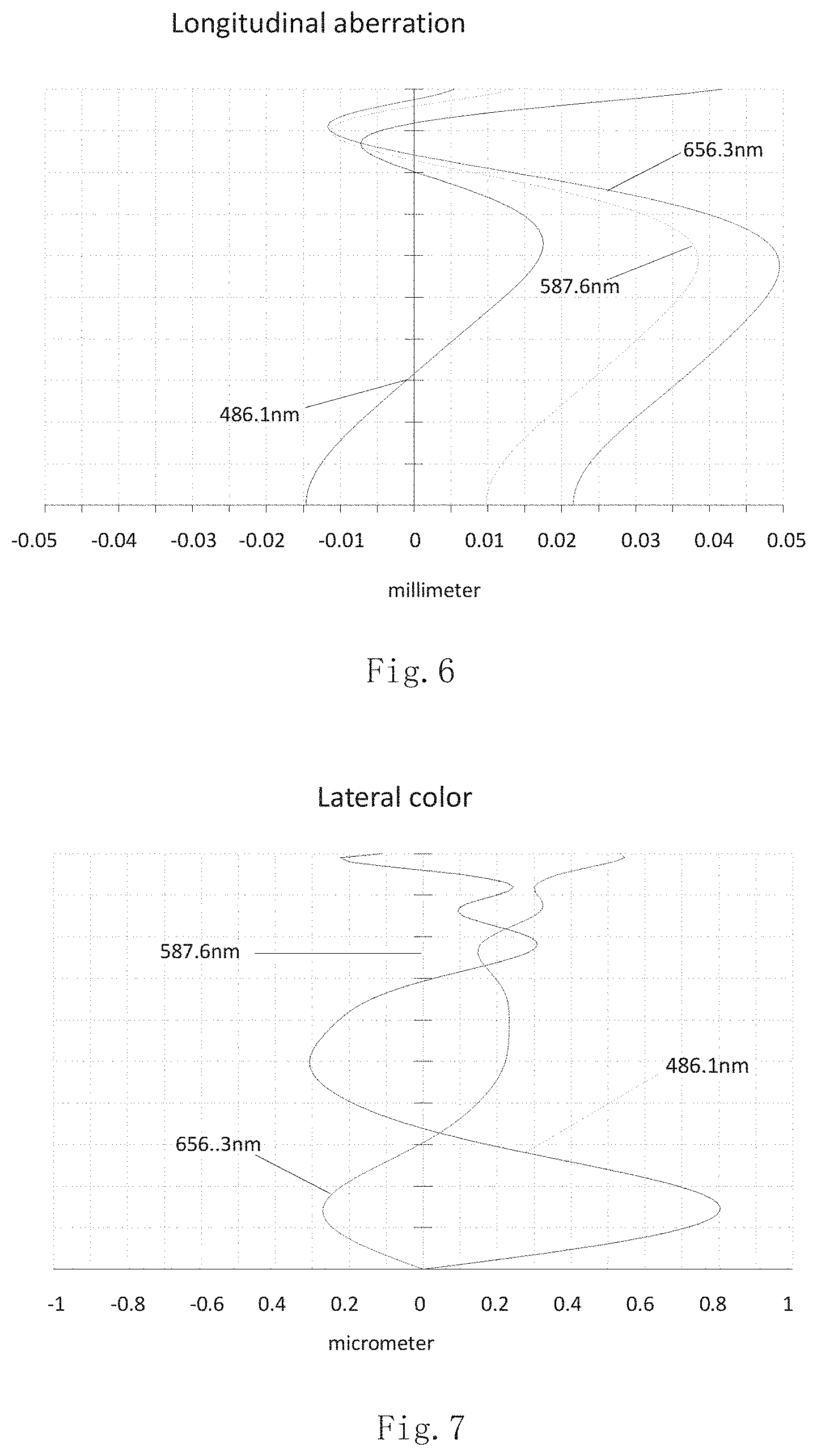
FIG. 6 shows the longitudinal aberration of the camera optical lens shown in FIG. 5;
FIG. 7 shows the lateral color of the camera optical lens shown in FIG. 5;
FIG. 8 shows the field curvature and distortion of the camera optical lens shown in FIG. 5:
FIG. 9 is a schematic diagram of a camera optical lens in accordance with a third embodiment of the present invention;
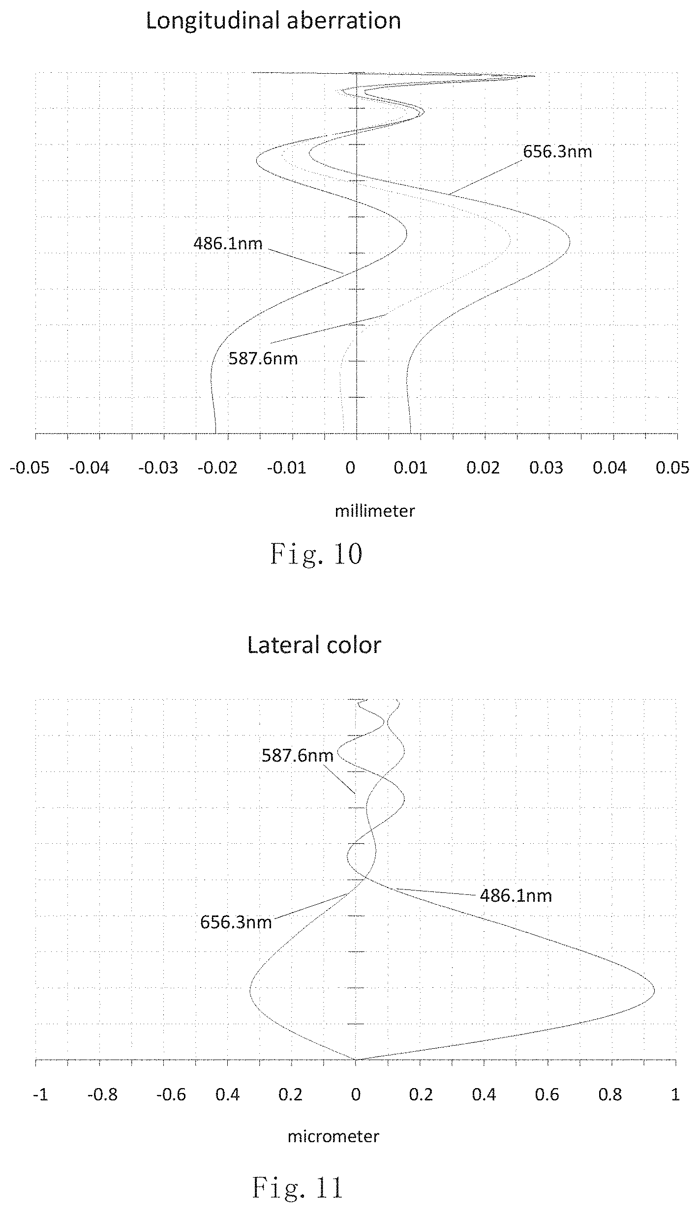
FIG. 10 shows the longitudinal aberration of the camera optical lens shown in FIG. 9;
FIG. 11 shows the lateral color of the camera optical lens shown in FIG. 9;
FIG. 12 shows the field curvature and distortion of the camera optical lens shown in FIG. 9.
DETAILED DESCRIPTION OF THE EXEMPLARY EMBODIMENTS
The present disclosure will hereinafter be described in detail with reference to several exemplary embodiments. To make the technical problems to be solved, technical solutions and beneficial effects of the present disclosure more apparent, the present disclosure is described in further detail together with the figure and the embodiments. It should be understood the specific embodiments described hereby is only to explain the disclosure, not intended to limit the disclosure.
Embodiment 1
As referring to FIG. 1, the present invention provides a camera optical lens 10. FIG. 1 shows the camera optical lens 10 of embodiment 1 of the present invention, the camera optical lens 10 comprises 6 lenses. Specifically, from the object side to the image side, the camera optical lens 10 comprises in sequence: an aperture S1, a first lens L1, a second lens L2, a third lens L3, a fourth lens L4, a fifth lens L5, and a sixth lens L6. Optical element like optical filter GF can be arranged between the sixth lens L6 and the image surface Si.
The first lens L1 is made of plastic material, the second lens L2 is made of plastic material, the third lens L3 is made of plastic material, the fourth lens L4 is made of plastic material, the fifth lens L5 is made of glass material, and the sixth lens L6 is made of plastic material.
In this embodiment, the second lens L2 has a positive refractive power. The third lens L3 has a negative refractive power.
Here, the focal length of the whole camera optical lens 10 is defined as f, the focal length of the first lens is defined as f1. The camera optical lens further satisfies the following condition: 0.5.ltoreq.f1/f.ltoreq.10, which fixes the positive refractive power of the first lens L1. If the lower limit of the set value is exceeded, although it benefits the ultra-thin development of lenses, but the positive refractive power of the first lens L1 will be too strong, problem like aberration is difficult to be corrected, and it is also unfavorable for wide-angle development of lens. On the contrary, if the upper limit of the set value is exceeded, the positive refractive power of the first lens L1 becomes too weak, it is then difficult to develop ultra-thin lenses. Preferably, the following condition shall be satisfied, 0.936.ltoreq.f1/f.ltoreq.7.4895.
The refractive power of the fifth lens L5 is defined as n5. Here the following condition should be satisfied: 1.7.ltoreq.n5.ltoreq.2.2. This condition fixes the refractive power of the fifth lens L5, and when the value of the refractive power within this range benefits the ultra-thin development of lenses, and it also benefits the correction of aberration. Preferably, the following condition shall be satisfied, 1.705.ltoreq.n5.ltoreq.2.1495.
The thickness on-axis of the fifth lens L5 is defined as d9, and the total optical length of the camera optical lens 10 is defined as TTL. The following condition: 0.01.ltoreq.d9/TTL.ltoreq.0.2 should be satisfied. This condition fixes the ratio between the thickness on-axis of the fifth lens L5 and the total optical length TTL. When the condition is satisfied, it is beneficial for realization of the ultra-thin lens. Preferably, the condition 0.0285.ltoreq.d9/TTL.ltoreq.0.141 shall be satisfied.
When the focal length of the camera optical lens 10 of the present invention, the focal length of each lens, the refractive power of the related lens, and the total optical length, the thickness on-axis and the curvature radius of the camera optical lens satisfy the above conditions, the camera optical lens 10 has the advantage of high performance and satisfies the design requirement of low TTL.
In this embodiment, the first lens L1 has a positive refractive power with a convex object side surface and a concave image side surface relative to the proximal axis.
The curvature radius of the object side surface of the first lens L1 is defined as R1, the curvature radius of the image side surface of the first lens L1 is defined as R2. The camera optical lens 10 further satisfies the following condition: -8.99.ltoreq.(R1+R2)/(R1-R2).ltoreq.-1.85, which fixes the shape of the first lens L1, by which, the shape of the first lens L1 can be reasonably controlled and it is effectively for correcting spherical aberration of the camera optical lens. Preferably, the condition: -5.62.ltoreq.(R1+R2)/(R1-R2).ltoreq.-2.31 shall be satisfied.
The thickness on-axis of the first lens L1 is defined as d1. The following condition: 0.12.ltoreq.d1.ltoreq.0.52 should be satisfied. When the condition is satisfied, it is beneficial for realization of the ultra-thin lens. Preferably, the condition 0.20.ltoreq.d1.ltoreq.0.41 shall be satisfied.
In this embodiment, the second lens L2 has a convex object side surface and a concave image side surface relative to the proximal axis.
The focal length of the whole camera optical lens 10 is f, the focal length of the second lens L2 is f2. The following condition should be satisfied: 0.67.ltoreq.f2/f.ltoreq.3.89. When the condition is satisfied, the positive refractive power of the second lens L2 is controlled within reasonable scope, the spherical aberration caused by the first lens L1 which has positive refractive power and the field curvature of the system then can be reasonably and effectively balanced. Preferably, the condition 1.07.ltoreq.f2/f.ltoreq.3.11 should be satisfied.
The curvature radius of the object side surface of the second lens L2 is defined as R3, the curvature radius of the image side surface of the second lens L2 is defined as R4. The following condition should be satisfied: -3.84.ltoreq.(R3+R4)/(R3-R4).ltoreq.-1.03, which fixes the shape of the second lens L2, when the value is beyond this range, with the development into the direction of ultra-thin and wide-angle lenses, problem like aberration of the on-axis Chromatic aberration is difficult to be corrected. Preferably, the following condition shall be satisfied, -2.405.ltoreq.(R3+R4)/(R3-R4).ltoreq.-1.82.
The thickness on-axis of the second lens L2 is defined as d3. The following condition: 0.31.ltoreq.d3.ltoreq.0.97 should be satisfied. When the condition is satisfied, it is beneficial for realization of the ultra-thin lens. Preferably, the condition 0.50.ltoreq.d3.ltoreq.0.78 shall be satisfied.
In this embodiment, the third lens L3 has a convex object side surface and a concave image side surface relative to the proximal axis.
The focal length of the whole camera optical lens 10 is f, the focal length of the third lens L3 is f3. The following condition should be satisfied: -4.46.ltoreq.f3/f.ltoreq.-1.16, by which the field curvature of the system then can be reasonably and effectively balanced. Preferably, the condition -2.79.ltoreq.f3/f.ltoreq.-1.46 should be satisfied.
The curvature radius of the object side surface of the third lens L3 is defined as R5, the curvature radius of the image side surface of the third lens L3 is defined as R6. The following condition should be satisfied: 1.43.ltoreq.(R5+R6)/(R5-R6).ltoreq.6.00, which is beneficial for the shaping of the third lens L3, and bad shaping and stress generation due to extra-large curvature of surface of the third lens L3 can be avoided. Preferably, the following condition shall be satisfied, 2.28.ltoreq.(R5+R6)/(R5-R6).ltoreq.4.80.
The thickness on-axis of the third lens L3 is defined as d5. The following condition: 0.11.ltoreq.d5.ltoreq.0.40 should be satisfied. When the condition is satisfied, it is beneficial for realization of the ultra-thin lens. Preferably, the condition 0.18.ltoreq.d5.ltoreq.0.32 shall be satisfied.
In this embodiment, the fourth lens L4 has a positive refractive power with a convex object side surface and a convex image side surface relative to the proximal axis.
The focal length of the whole camera optical lens 10 is f, the focal length of the fourth lens L4 is f4. The following condition should be satisfied: 0.945.ltoreq.f4/f.ltoreq.3.44, which can effectively reduce the sensitivity of lens group used in camera and further enhance the imaging quality. Preferably, the condition -1.51.ltoreq.f4/f.ltoreq.2.75 should be satisfied.
The curvature radius of the object side surface of the fourth lens L4 is defined as R7, the curvature radius of the image side surface of the fourth lens L4 is defined as R8. The following condition should be satisfied: -0.73.ltoreq.(R7+R8)/(R7-R8).ltoreq.-0.13, which fixes the shaping of the fourth lens L4. When beyond this range, with the development into the direction of ultra-thin and wide-angle lenses, problem like aberration of the off-axis picture angle is difficult to be corrected. Preferably, the following condition shall be satisfied, -0.45.ltoreq.(R7+R8)/(R7-R8).ltoreq.-0.16.
The thickness on-axis of the fourth lens L4 is defined as d7. The following condition: 0.15.ltoreq.d7.ltoreq.0.79 should be satisfied. When the condition is satisfied, it is beneficial for realization of the ultra-thin lens. Preferably, the condition 0.25.ltoreq.d7.ltoreq.0.63 shall be satisfied.
In this embodiment, the fifth lens L5 has a negative refractive power with a concave object side surface and a convex image side surface relative to the proximal axis.
The focal length of the whole camera optical lens 10 is f, the focal length of the fifth lens L5 is f5. The following condition should be satisfied: -4.41.ltoreq.f5/f.ltoreq.-1.02, which can effectively smooth the light angles of the camera and reduce the tolerance sensitivity. Preferably, the condition -2.75.ltoreq.f5/f.ltoreq.-1.28 should be satisfied.
The curvature radius of the object side surface of the fifth lens L5 is defined as R9, the curvature radius of the image side surface of the fifth lens L5 is defined as R10. The following condition should be satisfied: -5.19.ltoreq.(R9+R10)/(R9-R10).ltoreq.-1.34, by which, the shape of the fifth lens L5 is fixed, when beyond this range, with the development into the direction of ultra-thin and wide-angle lenses, problem like aberration of the off-axis picture angle is difficult to be corrected. Preferably, the following condition shall be satisfied, -3.25.ltoreq.(R9+R10)/(R9-R10).ltoreq.-1.67.
The thickness on-axis of the fifth lens L5 is defined as d9. The following condition: 0.13.ltoreq.d9.ltoreq.0.66 should be satisfied. When the condition is satisfied, it is beneficial for realization of the ultra-thin lens. Preferably, the condition 0.21.ltoreq.d9.ltoreq.0.52 shall be satisfied.
In this embodiment, the sixth lens L6 has a positive refractive power with a convex object side surface and a concave image side surface relative to the proximal axis.
The focal length of the whole camera optical lens 10 is f, the focal length of the sixth lens L6 is f6. The following condition should be satisfied: 1.96.ltoreq.f6/f.ltoreq.19.22, which can effectively reduce the sensitivity of lens group used in camera and further enhance the imaging quality. Preferably, the condition -3.14.ltoreq.f6/f.ltoreq.15.38 should be satisfied.
The curvature radius of the object side surface of the sixth lens L6 is defined as R11, the curvature radius of the image side surface of the sixth lens L6 is defined as R12. The following condition should be satisfied: -5.04.ltoreq.(R11+R12)/(R11-R12).ltoreq.39.82, by which, the shape of the sixth lens L6 is fixed, when beyond this range, with the development into the direction of ultra-thin and wide-angle lenses, problem like aberration of the off-axis picture angle is difficult to be corrected. Preferably, the following condition shall be satisfied, 8.06.ltoreq.(R11+R12)/(R11-R12).ltoreq.31.85.
The thickness on-axis of the sixth lens L6 is defined as d11. The following condition: 0.50.ltoreq.d11.ltoreq.1.71 should be satisfied. When the condition is satisfied, it is beneficial for realization of the ultra-thin lens. Preferably, the condition 0.80.ltoreq.d11.ltoreq.1.37 shall be satisfied.
The focal length of the whole camera optical lens 10 is f, the combined focal length of the first lens L1 and the second lens L2 is f12. The following condition should be satisfied: 0.44.ltoreq.f12/f.ltoreq.1.61, which can effectively avoid the aberration and field curvature of the camera optical lens, and can suppress the rear focal length for realizing the ultra-thin lens. Preferably, the condition 0.71.ltoreq.f12/f.ltoreq.1.28 should be satisfied.
In this embodiment, the total optical length TTL of the camera optical lens 10 is less than or equal to 6.14 mm, it is beneficial for the realization of ultra-thin lenses. Preferably, the total optical length TTL of the camera optical lens 10 is less than or equal to 5.86 mm.
In this embodiment, the aperture F number of the camera optical lens 10 is less than or equal to 2.06. A large aperture has better imaging performance. Preferably, the aperture F number of the camera optical lens 10 is less than or equal to 2.02.
With such design, the total optical length TTL of the whole camera optical lens 10 can be made as short as possible, thus the miniaturization characteristics can be maintained.
In the following, an example will be used to describe the camera optical lens 10 of the present invention. The symbols recorded in each example are as follows. The unit of distance, radius and center thickness is mm.
TTL: Optical length (the distance on-axis from the object side surface of the first lens L1 to the image surface).
Preferably, inflexion points and/or arrest points can also be arranged on the object side surface and/or image side surface of the lens, so that the demand for high quality imaging can be satisfied, the description below can be referred for specific implementable scheme.
The design information of the camera optical lens 10 in the first embodiment of the present invention is shown in the following, the unit of the focal length, distance, radius and center thickness is mm.
The design information of the camera optical lens 10 in the first embodiment of the present invention is shown in the tables 1 and 2.
TABLE-US-00001 TABLE 1 R d nd .nu.d S1 .infin. d0= -0.241 R1 2.012 d1= 0.345 nd1 1.6073 .nu.1 38.00 R2 4.218 d2= 0.061 R3 4.302 d3= 0.649 nd2 1.5422 .nu.2 55.90 R4 13.679 d4= 0.042 R5 4.941 d5= 0.229 nd3 1.6411 .nu.3 23.50 R6 2.500 d6= 0.226 R7 7.583 d7= 0.527 nd4 1.5208 .nu.4 55.80 R8 -16.255 d8= 0.452 R9 -3.725 d9= 0.437 nd5 1.7098 .nu.5 21.40 R10 -8.612 d10= 0.080 R11 1.702 d11= 1.119 nd6 1.5299 .nu.6 55.70 R12 1.395 d12= 0.466 R13 .infin. d13= 0.210 ndg 1.5168 .nu.g 64.17 R14 .infin. d14= 0.460
Where:
In which, the meaning of the various symbols is as follows.
S1: Aperture;
R: The curvature radius of the optical surface, the central curvature radius in case of lens;
R1: The curvature radius of the object side surface of the first lens L1;
R2: The curvature radius of the image side surface of the first lens L1;
R3: The curvature radius of the object side surface of the second lens L2;
R4: The curvature radius of the image side surface of the second lens L2;
R5: The curvature radius of the object side surface of the third lens L3;
R6: The curvature radius of the image side surface of the third lens L3;
R7: The curvature radius of the object side surface of the fourth lens L4;
R8: The curvature radius of the image side surface of the fourth lens L4;
R9: The curvature radius of the object side surface of the fifth lens L5;
R10: The curvature radius of the image side surface of the fifth lens L5;
R11: The curvature radius of the object side surface of the sixth lens L6;
R12: The curvature radius of the image side surface of the sixth lens L6;
R13: The curvature radius of the object side surface of the optical filter GF;
R14: The curvature radius of the image side surface of the optical filter GF;
d: The thickness on-axis of the lens and the distance on-axis between the lens;
d0: The distance on-axis from aperture S1 to the object side surface of the first lens L1;
d1: The thickness on-axis of the first lens L1;
d2: The distance on-axis from the image side surface of the first lens L1 to the object side surface of the second lens L2;
d3: The thickness on-axis of the second lens L2;
d4: The distance on-axis from the image side surface of the second lens L2 to the object side surface of the third lens L3;
d5: The thickness on-axis of the third lens L3;
d6: The distance on-axis from the image side surface of the third lens L3 to the object side surface of the fourth lens L4;
d7: The thickness on-axis of the fourth lens L4;
d8: The distance on-axis from the image side surface of the fourth lens L4 to the object side surface of the fifth lens L5;
d9: The thickness on-axis of the fifth lens L5;
d10: The distance on-axis from the image side surface of the fifth lens L5 to the object side surface of the sixth lens L6;
d11: The thickness on-axis of the sixth lens L6;
d12: The distance on-axis from the image side surface of the sixth lens L6 to the object side surface of the optical filter GF;
d13: The thickness on-axis of the optical filter GF;
d14: The distance on-axis from the image side surface to the image surface of the optical filter GF;
nd: The refractive power of the d line;
nd1: The refractive power of the d line of the first lens L1;
nd2: The refractive power of the d line of the second lens L2;
nd3: The refractive power of the d line of the third lens L3;
nd4: The refractive power of the d line of the fourth lens L4;
nd5: The refractive power of the d line of the fifth lens L5;
nd6: The refractive power of the d line of the sixth lens L6; ndg: The refractive power of the d line of the optical filter GF;
vd: The abbe number;
v1: The abbe number of the first lens L1;
v2: The abbe number of the second lens L2;
v3: The abbe number of the third lens L3;
v4: The abbe number of the fourth lens L4;
v5: The abbe number of the fifth lens L5;
v6: The abbe number of the sixth lens L6;
vg: The abbe number of the optical filter GF.
Table 2 shows the aspherical surface data of the camera optical lens 10 in the embodiment 1 of the present invention.
TABLE-US-00002 TABLE 2 Conic index Aspherical Surface Index k A4 A6 A8 A10 A12 A14 A16 R1 -1.7693E-02 -0.015755153 -0.005619936 -0.017366613 0.013579681 -0.00891- 6195 0.005161853 -1.81E-03 R2 8.2647E+00 -0.018521324 -0.049796228 0.032663229 0.003691312 -0.0127504- 19 0.004594313 -0.001410178 R3 4.0097E+00 0.022433871 -0.029935749 0.011907488 0.041732918 -0.02778651- 3 -0.001459045 0.001729615 R4 -3.6739E+02 -0.028602589 0.014407165 -0.13679632 0.07018318 0.015716381- -0.013011494 0.000878518 R5 -9.0569E-01 -0.129209 -0.002749979 -0.039671581 -0.034356267 0.08657715- 8 -0.031362133 0.001923009 R6 -1.0304E+01 -0.017322692 0.042563758 -0.12734331 0.19656843 -0.12992349- 0.032383609 0.000776349 R7 -1.0281E+02 0.005163059 -0.014196842 0.069794768 -0.056917656 -0.003546- 936 2.43E-02 -9.16E-03 R8 -3.4048E+02 -0.005028303 -0.07834237 0.12495106 -0.097215508 0.04230634- 9 -6.65E-03 -2.28E-04 R9 -3.2712E+01 0.13700483 -0.2898899 0.3943106 -0.43845423 3.05E-01 -1.16E- -01 1.77E-02 R10 -1.8369E+01 -0.091973102 0.21114286 -0.26301251 1.74E-01 -6.53E-02 1.2- 7E-02 -9.86E-04 R11 -1.6108E+01 -0.091973102 0.031350515 -0.003239156 2.08336E-05 4.23233E- -05 2.18E-06 -9.43E-07 R12 -5.0620E+00 -0.13601557 0.015638722 -0.002691807 1.83E-04 3.00E-06 -6.- 16E-07 -8.18E-09
Among them, K is a conic index, A4, A6, A8, A10, A12, A14, A16 are aspheric surface indexes.
IH: Image height y=(x.sup.2/R)/[1+{1-(k+1)(x.sup.2/R.sup.2)}.sup.1/2]+A4x.sup.4+A6x.sup.6+- A8x.sup.8+A10x.sup.10+A12x.sup.12+A14x.sup.14+A16x.sup.16 (1)
For convenience, the aspheric surface of each lens surface uses the aspheric surfaces shown in the above condition (1). However, the present invention is not limited to the aspherical polynomials form shown in the condition (1).
Table 3 and table 4 show the inflexion points and the arrest point design data of the camera optical lens 10 lens in embodiment 1 of the present invention. In which, P1R1 and P1R2 represent respectively the object side surface and image side surface of the first lens L1, P2R1 and P2R2 represent respectively the object side surface and image side surface of the second lens L2, P3R1 and P3R2 represent respectively the object side surface and image side surface of the third lens L3, P4R1 and P4R2 represent respectively the object side surface and image side surface of the fourth lens L4, P5R1 and P5R2 represent respectively the object side surface and image side surface of the fifth lens L5, P6R1 and P6R2 represent respectively the object side surface and image side surface of the sixth lens L6. The data in the column named "inflexion point position" are the vertical distances from the inflexion points arranged on each lens surface to the optic axis of the camera optical lens 10. The data in the column named "arrest point position" are the vertical distances from the arrest points arranged on each lens surface to the optic axis of the camera optical lens 10.
TABLE-US-00003 TABLE 3 Inflexion point number Inflexion point position 1 Inflexion point position 2 P1R1 1 0.995 P1R2 1 0.995 P2R1 1 1.095 P2R2 1 0.365 P3R1 2 0.365 1.045 P3R2 0 P4R1 1 1.075 P4R2 1 0.945 P5R1 0 P5R2 0 P6R1 2 0.405 1.745 P6R2 1 0.695
TABLE-US-00004 TABLE 4 Arrest point number Arrest point position 1 Arrest point position 2 P1R1 0 P1R2 0 P2R1 0 P2R2 1 0.565 P3R1 2 0.595 1.225 P3R2 0 P4R1 1 1.215 P4R2 1 1.175 P5R1 0 P5R2 0 P6R1 1 0.805 P6R2 1 1.615
FIG. 2 and FIG. 3 show the longitudinal aberration and lateral color schematic diagrams after light with a wavelength of 486.1 nm, 587.6 nm and 656.3 nm passes the camera optical lens 10 in the first embodiment. FIG. 4 shows the field curvature and distortion schematic diagrams after light with a wavelength of 587.6 nm passes the camera optical lens 10 in the first embodiment, the field curvature S in FIG. 4 is a field curvature in the sagittal direction, T is a field curvature in the meridian direction.
Table 13 shows the various values of the embodiments 1, 2, 3, and the values corresponding with the parameters which are already specified in the conditions.
As shown in Table 13, the first embodiment satisfies the various conditions.
In this embodiment, the pupil entering diameter of the camera optical lens is 2.17955 mm, the full vision field image height is 3.512 mm, the vision field angle in the diagonal direction is 77.710, it has wide-angle and is ultra-thin, its on-axis and off-axis chromatic aberrations are fully corrected, and it has excellent optical characteristics.
Embodiment 2
Embodiment 2 is basically the same as embodiment 1, the meaning of its symbols is the same as that of embodiment 1, in the following, only the differences are described.
Table 5 and table 6 show the design data of the camera optical lens 20 in embodiment 2 of the present invention.
TABLE-US-00005 TABLE 5 R d nd .nu.d S1 .infin. d0 = -0.243 R1 1.986 d1 = 0.338 nd1 1.5957 .nu.1 38.00 R2 4.226 d2 = 0.058 R3 4.289 d3 = 0.633 nd2 1.5314 .nu.2 55.90 R4 20.190 d4 = 0.038 R5 5.090 d5 = 0.235 nd3 1.6448 .nu.3 23.50 R6 2.448 d6 = 0.221 R7 6.982 d7 = 0.517 nd4 1.5042 .nu.4 55.80 R8 -10.362 d8 = 0.486 R9 -3.890 d9 = 0.408 nd5 2.0995 .nu.5 21.40 R10 -8.763 d10 = 0.143 R11 1.650 d11 = 1.142 nd6 1.5470 .nu.6 55.70 R12 1.419781 d12 = 0.440 R13 .infin. d13 = 0.210 ndg 1.5168 .nu.g 64.17 R14 .infin. d14 = 0.434
Table 6 shows the aspherical surface data of each lens of the camera optical lens 20 in embodiment 2 of the present invention.
TABLE-US-00006 TABLE 6 Conic Index Aspherical Surface Index k A4 A6 A8 A10 A12 A14 A16 R1 -2.4281E-02 -0.016126034 -0.005729444 -0.017291768 0.013629076 -0.00890- 1931 0.005136218 -1.84E-03 R2 8.3193E+00 -0.018755434 -0.049541655 0.032845918 0.003838163 -0.0126086- 22 0.004720242 -0.001306139 R3 4.1682E+00 0.023274837 -0.029985994 0.011995116 0.041864856 -0.02767775- 6 -0.001397665 0.00177375 R4 -3.8814E+02 -0.028494684 0.014502692 -0.13685338 0.070109691 0.01564057- -0.01305399 8.62E-04 R5 1.9945E-01 -0.12817551 -0.002696794 -0.039896256 -0.034402239 0.0864178- 12 -0.031367949 0.001913335 R6 -1.0412E+01 -0.015775921 0.042259009 -0.12900001 0.19600877 -0.12990113- 0.032573046 0.000939609 R7 -9.8208E+01 0.011624776 -0.010850127 0.068773614 -0.057396141 -0.003509- 835 0.024468309 -8.95E-03 R8 -6.7748E+02 -0.004567156 -0.081556225 0.12604503 -0.096262427 0.0426464- 16 -0.006640056 -3.37E-04 R9 -2.2977E+01 0.13156402 -0.28844211 0.39605316 -0.43754137 0.30516369 -1.16E-01 0.017607352 R10 -1.3785E+01 -0.093125101 0.21017922 -0.26326232 0.17435179 -0.06517285- 7 0.012673731 -9.97E-04 R11 -1.7654E+01 -0.093125101 0.03158491 -0.003369585 -1.88119E-05 3.89567E- -05 2.64004E-06 -6.08E-07 R12 -4.7482E+00 -0.13616473 0.015535441 -0.002699091 1.83E-04 3.22E-06 -5.32E-07 -1.60E-08
Table 7 and table 8 show the inflexion points and the arrest point design data of the camera optical lens 20 lens in embodiment 2 of the present invention.
TABLE-US-00007 TABLE 7 Inflexion point number Inflexion point position 1 Inflexion point position 2 P1R1 1 0.995 P1R2 1 1.045 P2R1 1 1.105 P2R2 1 0.335 P3R1 2 0.355 1.045 P3R2 0 P4R1 1 1.115 P4R2 1 0.925 P5R1 0 P5R2 0 P6R1 2 0.395 1.835 P6R2 1 0.715
TABLE-US-00008 TABLE 8 Arrest point number Arrest point position 1 Arrest point position 2 P1R1 0 P1R2 0 P2R1 0 P2R2 1 0.525 P3R1 2 0.595 1.235 P3R2 0 P4R1 0 P4R2 1 1.135 P5R1 0 P5R2 0 P6R1 1 0.795 P6R2 1 1.615
FIG. 6 and FIG. 7 show the longitudinal aberration and lateral color schematic diagrams after light with a wavelength of 486.1 nm, 587.6 nm and 656.3 nm passes the camera optical lens 20 in the second embodiment. FIG. 8 shows the field curvature and distortion schematic diagrams after light with a wavelength of 587.6 nm passes the camera optical lens 20 in the second embodiment.
As shown in Table 13, the second embodiment satisfies the various conditions.
In this embodiment, the pupil entering diameter of the camera optical lens is 2.1694 mm, the full vision field image height is 3.512 mm, the vision field angle in the diagonal direction is 77.98.degree., it has wide-angle and is ultra-thin, its on-axis and off-axis chromatic aberrations are fully corrected, and it has excellent optical characteristics.
Embodiment 3
Embodiment 3 is basically the same as embodiment 1, the meaning of its symbols is the same as that of embodiment 1, in the following, only the differences are described.
Table 9 and table 10 show the design data of the camera optical lens 30 in embodiment 3 of the present invention.
TABLE-US-00009 TABLE 9 R d nd .nu.d S1 .infin. d0= -0.380 R1 2.283 d1= 0.249 nd1 1.2612 .nu.1 38.00 R2 3.591 d2= 0.029 R3 2.670 d3= 0.625 nd2 1.5813 .nu.2 55.90 R4 9.351 d4= 0.224 R5 4.014 d5= 0.267 nd3 1.6216 .nu.3 23.50 R6 2.408 d6= 0.288 R7 6.867 d7= 0.307 nd4 1.5045 .nu.4 55.80 R8 -12.220 d8= 0.687 R9 -4.339 d9= 0.260 nd5 1.7100 .nu.5 21.40 R10 -12.972 d10= 0.238 R11 1.496 d11= 0.997 nd6 1.5051 .nu.6 55.70 R12 1.387409 d12= 0.601 R13 .infin. d13= 0.210 ndg 1.5168 .nu.g 64.17 R14 .infin. d14= 0.596
Table 10 shows the aspherical surface data of each lens of the camera optical lens 30 in embodiment 3 of the present invention.
TABLE-US-00010 TABLE 10 Conic Index Aspherical Surface Index k A4 A6 A8 A10 A12 A14 A16 R1 8.3357E-01 -0.003162172 0.007772566 -0.015301087 0.014788715 -0.0065151- 65 0.008944767 7.62E-04 R2 8.8624E+00 -0.017815392 -0.040513107 0.040060459 0.009900602 -0.0135161- 52 0.004954335 -0.000758143 R3 2.1989E+00 0.021371698 -0.032507776 0.006526166 0.032608994 -0.03101252- 1 0.000229096 0.003236629 R4 9.6015E-01 -0.021898357 0.029930424 -0.12949386 0.069365591 0.013768057- -0.012847467 -0.00089207 R5 -8.4881E+00 -0.14556774 -0.00738353 -0.045867904 -0.037318394 0.0884440- 55 -0.030052862 0.003013774 R6 -9.4908E+00 -0.025325022 0.018288381 -0.15739663 0.17398563 -0.13525213- 0.037976613 0.005019564 R7 -1.6052E+02 0.003565916 -0.026981527 0.055670929 -0.064663115 -0.006266- 414 0.022986809 -0.009487264 R8 5.4061E+01 -0.020210132 -0.082321217 0.12379187 -0.098095663 0.04195043- 7 -0.006984909 1.11E-04 R9 -2.6100E+01 0.14871597 -0.29004926 0.39299704 -0.43970442 0.30473982 -1- .16E-01 1.79E-02 R10 -5.9241E+02 -0.11179914 0.21289335 -0.26549579 0.17406184 -0.06531265 - 0.012630418 -1.02E-03 R11 -1.1232E+01 -0.11179914 0.030345172 -0.003528525 -2.34097E-05 3.76135E- -05 2.1181E-06 -7.33E-07 R12 -5.8156E+00 -0.1367919 0.015851788 -0.002675886 1.84E-04 3.09E-06 -6.4- 3E-07 -1.39E-08
Table 11 and table 12 show the inflexion points and the arrest point design data of the camera optical lens 30 lens in embodiment 3 of the present invention.
TABLE-US-00011 TABLE 11 Inflexion point number Inflexion point position 1 Inflexion point position 2 P1R1 0 P1R2 0 P2R1 1 1.045 P2R2 1 0.515 P3R1 2 0.355 1.045 P3R2 2 0.575 1.135 P4R1 1 0.615 P4R2 1 1.165 P5R1 1 1.435 P5R2 0 P6R1 1 0.435 P6R2 1 0.655
TABLE-US-00012 TABLE 12 Arrest point number Arrest point position 1 Arrest point position 2 P1R1 0 P1R2 0 P2R1 0 P2R2 1 0.755 P3R1 2 0.595 1.195 P3R2 1 0.875 P4R1 1 0.865 P4R2 0 P5R1 0 P5R2 0 P6R1 1 0.865 P6R2 1 1.515
FIG. 10 and FIG. 11 show the longitudinal aberration and lateral color schematic diagrams after light with a wavelength of 486.1 nm, 587.6 nm and 656.3 nm passes the camera optical lens 30 in the third embodiment. FIG. 12 shows the field curvature and distortion schematic diagrams after light with a wavelength of 587.6 nm passes the camera optical lens 30 in the third embodiment.
As shown in Table 13, the third embodiment satisfies the various conditions.
In this embodiment, the pupil entering diameter of the camera optical lens is 2.31937 mm, the full vision field image height is 3.512 mm, the vision field angle in the diagonal direction is 74.26.degree., it has wide-angle and is ultra-thin, its on-axis and off-axis chromatic aberrations are fully corrected, and it has excellent optical characteristics.
TABLE-US-00013 TABLE 13 Embodiment Embodiment 1 2 Embodiment 3 f 4.359 4.339 4.639 f1 5.981 5.953 23.095 f2 11.301 10.109 6.215 f3 -8.191 -7.577 -10.343 f4 10.004 8.356 8.761 f5 -9.607 -6.653 -9.299 f6 55.864 24.634 18.184 f12 3.971 3.824 4.965 (R1 + R2)/(R1 - R2) -2.824 -2.773 -4.493 (R3 + R4)/(R3 - R4) -1.918 -1.540 -1.799 (R5 + R6)/(R5 - R6) 3.048 2.853 3.999 (R7 + R8)/(R7 - R8) -0.364 -0.195 -0.280 (R9 + R10)/(R9 - R10) -2.525 -2.596 -2.005 (R11 + R12)/(R11 - R12) 10.078 13.344 26.545 f1/f 1.372 1.372 4.979 f2/f 2.593 2.330 1.340 f3/f -1.879 -1.746 -2.230 f4/f 2.295 1.926 1.889 f5/f -2.204 -1.533 -2.005 f6/f 12.815 5.678 3.920 f12/f 0.911 0.881 1.070 d1 0.345 0.338 0.249 d3 0.649 0.633 0.625 d5 0.229 0.235 0.267 d7 0.527 0.517 0.307 d9 0.437 0.408 0.260 d11 1.119 1.142 0.997 Fno 2.000 2.000 2.000 TTL 5.302 5.303 5.579 d1/TTL 0.065 0.064 0.045 d3/TTL 0.122 0.119 0.112 d5/TTL 0.043 0.044 0.048 d7/TTL 0.099 0.097 0.055 d9/TTL 0.082 0.077 0.047 d11/TTL 0.211 0.215 0.179 n1 1.6073 1.5957 1.2612 n2 1.5422 1.5314 1.5813 n3 1.6411 1.6448 1.6216 n4 1.5208 1.5042 1.5045 n5 1.7098 2.0995 1.7100 n6 1.5299 1.5470 1.5051 v1 38.0000 38.0000 38.0000 v2 55.9000 55.9000 55.9000 v3 23.5000 23.5000 23.5000 v4 55.8000 55.8000 55.8000 v5 21.4000 21.4000 21.4000 v6 55.7000 55.7000 55.7000
It is to be understood, however, that even though numerous characteristics and advantages of the present exemplary embodiments have been set forth in the foregoing description, together with details of the structures and functions of the embodiments, the disclosure is illustrative only, and changes may be made in detail, especially in matters of shape, size, and arrangement of parts within the principles of the invention to the full extent indicated by the broad general meaning of the terms where the appended claims are expressed.
* * * * *
D00000
D00001
D00002
D00003
D00004
D00005
D00006
D00007
XML
uspto.report is an independent third-party trademark research tool that is not affiliated, endorsed, or sponsored by the United States Patent and Trademark Office (USPTO) or any other governmental organization. The information provided by uspto.report is based on publicly available data at the time of writing and is intended for informational purposes only.
While we strive to provide accurate and up-to-date information, we do not guarantee the accuracy, completeness, reliability, or suitability of the information displayed on this site. The use of this site is at your own risk. Any reliance you place on such information is therefore strictly at your own risk.
All official trademark data, including owner information, should be verified by visiting the official USPTO website at www.uspto.gov. This site is not intended to replace professional legal advice and should not be used as a substitute for consulting with a legal professional who is knowledgeable about trademark law.