Transvascular nerve stimulation apparatus and methods
Hoffer December 15, 2
U.S. patent number 10,864,374 [Application Number 16/012,013] was granted by the patent office on 2020-12-15 for transvascular nerve stimulation apparatus and methods. This patent grant is currently assigned to Lungpacer Medical Inc.. The grantee listed for this patent is Lungpacer Medical Inc.. Invention is credited to Joaquin Andres Hoffer.


View All Diagrams
| United States Patent | 10,864,374 |
| Hoffer | December 15, 2020 |
Transvascular nerve stimulation apparatus and methods
Abstract
Electrode structures for transvascular nerve stimulation combine electrodes with an electrically-insulating backing layer. The backing layer increases the electrical impedance of electrical paths through blood in a lumen of a blood vessel and consequently increases the flow of electrical current through surrounding tissues. The electrode structures may be applied to stimulate nerves such as the phrenic vagus, trigeminal, obturator or other nerves.
| Inventors: | Hoffer; Joaquin Andres (Anmore, CA) | ||||||||||
|---|---|---|---|---|---|---|---|---|---|---|---|
| Applicant: |
|
||||||||||
| Assignee: | Lungpacer Medical Inc.
(Burnaby, CA) |
||||||||||
| Family ID: | 1000005242439 | ||||||||||
| Appl. No.: | 16/012,013 | ||||||||||
| Filed: | June 19, 2018 |
Prior Publication Data
| Document Identifier | Publication Date | |
|---|---|---|
| US 20180296835 A1 | Oct 18, 2018 | |
Related U.S. Patent Documents
| Application Number | Filing Date | Patent Number | Issue Date | ||
|---|---|---|---|---|---|
| 15252687 | Aug 31, 2016 | 10022546 | |||
| 14792006 | Feb 14, 2017 | 9566436 | |||
| 14448734 | Aug 18, 2015 | 9108059 | |||
| 14044466 | Dec 29, 2015 | 9220898 | |||
| 12524571 | Oct 29, 2013 | 8571662 | |||
| PCT/CA2008/000179 | Jan 29, 2008 | ||||
| 60887031 | Jan 29, 2007 | ||||
| Current U.S. Class: | 1/1 |
| Current CPC Class: | A61N 1/36185 (20130101); A61N 1/3611 (20130101); A61N 1/05 (20130101); A61N 1/3601 (20130101); A61N 1/0558 (20130101); A61N 1/36139 (20130101); A61N 1/0551 (20130101) |
| Current International Class: | A61N 1/36 (20060101); A61N 1/05 (20060101) |
References Cited [Referenced By]
U.S. Patent Documents
| 1693734 | December 1928 | Waggoner |
| 2532788 | December 1950 | Sarnoff |
| 2664880 | January 1954 | Wales, Jr. |
| 3348548 | October 1967 | Chardack |
| 3470876 | October 1969 | Barchilon |
| 3769984 | November 1973 | Muench |
| 3804098 | April 1974 | Friedman |
| 3817241 | June 1974 | Grausz |
| 3835864 | September 1974 | Rasor et al. |
| 3847157 | November 1974 | Caillouette et al. |
| 3851641 | December 1974 | Toole et al. |
| 3896373 | July 1975 | Zelby |
| 3938502 | February 1976 | Bom |
| 3983881 | October 1976 | Wickham |
| 4054881 | October 1977 | Raab |
| 4072146 | February 1978 | Howes |
| 4114601 | September 1978 | Abels |
| 4173228 | November 1979 | Childress et al. |
| 4249539 | February 1981 | Mezrich et al. |
| 4317078 | February 1982 | Weed et al. |
| 4380237 | April 1983 | Newbower |
| 4407294 | October 1983 | Vilkomerson |
| 4416289 | November 1983 | Bresler |
| 4431005 | February 1984 | McCormick |
| 4431006 | February 1984 | Trimmer et al. |
| 4445501 | May 1984 | Bresler |
| RE31873 | April 1985 | Howes |
| 4573481 | March 1986 | Bullara |
| 4586923 | May 1986 | Gould et al. |
| 4587975 | May 1986 | Salo et al. |
| 4643201 | February 1987 | Stokes |
| 4674518 | June 1987 | Salo |
| 4681117 | July 1987 | Brodman et al. |
| 4683890 | August 1987 | Hewson |
| 4697595 | October 1987 | Breyer et al. |
| 4706681 | November 1987 | Breyer et al. |
| 4771788 | September 1988 | Millar |
| 4819662 | April 1989 | Heil, Jr. et al. |
| 4827935 | May 1989 | Geddes et al. |
| 4830008 | May 1989 | Meer |
| 4840182 | June 1989 | Carlson |
| 4852580 | August 1989 | Wood |
| 4860769 | August 1989 | Fogarty et al. |
| 4905698 | March 1990 | Strohl, Jr. et al. |
| 4911174 | March 1990 | Pederson et al. |
| 4934049 | June 1990 | Kiekhafer et al. |
| 4944088 | July 1990 | Doan et al. |
| 4951682 | August 1990 | Petre |
| 4957110 | September 1990 | Vogel et al. |
| 4989617 | February 1991 | Memberg et al. |
| 5005587 | April 1991 | Scott |
| 5010895 | April 1991 | Maurer |
| 5036848 | August 1991 | Hewson |
| 5042143 | August 1991 | Holleman et al. |
| 5056519 | October 1991 | Vince |
| 5115818 | May 1992 | Holleman et al. |
| 5146918 | September 1992 | Kallok et al. |
| 5170802 | December 1992 | Mehra |
| 5184621 | February 1993 | Vogel et al. |
| 5224491 | July 1993 | Mehra |
| 5243995 | September 1993 | Maier |
| 5265604 | November 1993 | Vince |
| 5267569 | December 1993 | Lienhard |
| 5314463 | May 1994 | Camps et al. |
| 5316009 | May 1994 | Yamada |
| 5324322 | June 1994 | Grill, Jr. et al. |
| 5330522 | July 1994 | Kreyenhagen |
| 5345936 | September 1994 | Pomeranz et al. |
| 5383923 | January 1995 | Webster, Jr. |
| 5411025 | May 1995 | Webster, Jr. |
| 5417208 | May 1995 | Winkler |
| 5451206 | September 1995 | Young |
| 5456254 | October 1995 | Pietroski et al. |
| 5465717 | November 1995 | Imran et al. |
| 5476498 | December 1995 | Ayers |
| 5486159 | January 1996 | Mahurkar |
| 5507725 | April 1996 | Savage et al. |
| 5524632 | June 1996 | Stein et al. |
| 5527358 | June 1996 | Mehmanesh et al. |
| 5531686 | July 1996 | Lundquist et al. |
| 5549655 | August 1996 | Erickson |
| 5555618 | September 1996 | Winkler |
| 5567724 | October 1996 | Kelleher et al. |
| 5584873 | December 1996 | Shoberg et al. |
| 5604231 | February 1997 | Smith et al. |
| 5665103 | September 1997 | Lafontaine et al. |
| 5678535 | October 1997 | DiMarco |
| 5683370 | November 1997 | Luther et al. |
| 5709853 | January 1998 | Iino et al. |
| 5716392 | February 1998 | Bourgeois et al. |
| 5733255 | March 1998 | Dinh et al. |
| 5755765 | May 1998 | Hyde et al. |
| 5776111 | July 1998 | Tesio |
| 5779732 | July 1998 | Amundson |
| 5782828 | July 1998 | Chen et al. |
| 5785706 | July 1998 | Bednarek |
| 5788681 | August 1998 | Weaver et al. |
| 5813399 | September 1998 | Isaza et al. |
| 5814086 | September 1998 | Hirschberg et al. |
| RE35924 | October 1998 | Winkler |
| 5824027 | October 1998 | Hoffer et al. |
| 5827192 | October 1998 | Gopakumaran et al. |
| 5916163 | June 1999 | Panescu et al. |
| 5944022 | August 1999 | Nardella et al. |
| 5954761 | September 1999 | Machek et al. |
| 5967978 | October 1999 | Littmann et al. |
| 5971933 | October 1999 | Gopakumaran et al. |
| 5983126 | November 1999 | Wittkampf |
| 6006134 | December 1999 | Hill et al. |
| 6024702 | February 2000 | Iversen |
| 6096728 | August 2000 | Collins et al. |
| 6120476 | September 2000 | Fung et al. |
| 6123699 | September 2000 | Webster, Jr. |
| 6126649 | October 2000 | Vantassel et al. |
| 6136021 | October 2000 | Tockman et al. |
| 6157862 | December 2000 | Brownlee et al. |
| 6161029 | December 2000 | Spreigl et al. |
| 6166048 | December 2000 | Bencherif |
| 6171277 | January 2001 | Ponzi |
| 6183463 | February 2001 | Webster, Jr. |
| 6198970 | March 2001 | Freed et al. |
| 6198974 | March 2001 | Webster, Jr. |
| 6201994 | March 2001 | Warman et al. |
| 6208881 | March 2001 | Champeau |
| 6210339 | April 2001 | Kiepen et al. |
| 6212435 | April 2001 | Lattner et al. |
| 6216045 | April 2001 | Black et al. |
| 6236892 | May 2001 | Feler |
| 6240320 | May 2001 | Spehr et al. |
| 6251126 | June 2001 | Ottenhoff et al. |
| 6269269 | July 2001 | Ottenhoff et al. |
| 6292695 | September 2001 | Webster, Jr. et al. |
| 6295475 | September 2001 | Morgan |
| 6322559 | November 2001 | Daulton |
| 6360740 | March 2002 | Ward et al. |
| 6397108 | May 2002 | Camps et al. |
| 6400976 | June 2002 | Champeau |
| 6415183 | July 2002 | Scheiner et al. |
| 6415187 | July 2002 | Kuzma et al. |
| 6438427 | August 2002 | Rexhausen et al. |
| 6445953 | September 2002 | Bulkes et al. |
| 6449507 | September 2002 | Hill et al. |
| 6463327 | October 2002 | Lurie et al. |
| 6493590 | December 2002 | Wessman et al. |
| 6508802 | January 2003 | Rosengart et al. |
| 6526321 | February 2003 | Spehr |
| 6569114 | May 2003 | Ponzi et al. |
| 6584362 | June 2003 | Scheiner et al. |
| 6585718 | July 2003 | Hayzelden et al. |
| 6587726 | July 2003 | Lurie et al. |
| 6602242 | August 2003 | Fung et al. |
| 6610713 | August 2003 | Tracey |
| 6630611 | October 2003 | Malowaniec |
| 6643552 | November 2003 | Edell et al. |
| 6651652 | November 2003 | Waard |
| 6682526 | January 2004 | Jones et al. |
| 6702780 | March 2004 | Gilboa et al. |
| 6718208 | April 2004 | Hill et al. |
| 6721603 | April 2004 | Zabara et al. |
| 6757970 | July 2004 | Kuzma et al. |
| 6778854 | August 2004 | Puskas |
| 6779257 | August 2004 | Kiepen et al. |
| 6844713 | January 2005 | Steber et al. |
| RE38705 | February 2005 | Hill et al. |
| 6881211 | April 2005 | Schweikert et al. |
| 6885888 | April 2005 | Rezai |
| 6907285 | June 2005 | Denker et al. |
| 6934583 | August 2005 | Weinberg et al. |
| 6981314 | January 2006 | Black et al. |
| 6999820 | February 2006 | Jordan |
| 7018374 | March 2006 | Schon et al. |
| 7047627 | May 2006 | Black et al. |
| 7071194 | July 2006 | Teng |
| 7072720 | July 2006 | Puskas |
| 7077823 | July 2006 | McDaniel |
| 7082331 | July 2006 | Park et al. |
| 7130700 | October 2006 | Gardeski et al. |
| 7142903 | November 2006 | Rodriguez et al. |
| 7149585 | December 2006 | Wessman et al. |
| 7155278 | December 2006 | King et al. |
| 7168429 | January 2007 | Matthews et al. |
| 7184829 | February 2007 | Hill et al. |
| 7206636 | April 2007 | Turcott |
| 7212867 | May 2007 | Van et al. |
| 7225016 | May 2007 | Koh |
| 7225019 | May 2007 | Jahns et al. |
| 7229429 | June 2007 | Martin et al. |
| 7231260 | June 2007 | Wallace et al. |
| 7235070 | June 2007 | Vanney |
| 7269459 | September 2007 | Koh |
| 7277757 | October 2007 | Casavant et al. |
| 7283875 | October 2007 | Larsson |
| 7340302 | March 2008 | Falkenberg et al. |
| 7363085 | April 2008 | Benser et al. |
| 7363086 | April 2008 | Koh et al. |
| 7371220 | May 2008 | Koh et al. |
| 7416552 | August 2008 | Paul et al. |
| 7421296 | September 2008 | Benser et al. |
| 7454244 | November 2008 | Kassab et al. |
| 7519425 | April 2009 | Benser et al. |
| 7519426 | April 2009 | Koh et al. |
| 7522953 | April 2009 | Gharib et al. |
| 7553305 | June 2009 | Honebrink et al. |
| 7555349 | June 2009 | Wessman et al. |
| 7569029 | August 2009 | Clark et al. |
| 7591265 | September 2009 | Lee et al. |
| 7593760 | September 2009 | Rodriguez et al. |
| 7613524 | November 2009 | Jordan |
| 7636600 | December 2009 | Koh |
| 7670284 | March 2010 | Padget et al. |
| 7672728 | March 2010 | Libbus et al. |
| 7672729 | March 2010 | Koh et al. |
| 7676275 | March 2010 | Farazi et al. |
| 7676910 | March 2010 | Kiepen et al. |
| 7697984 | April 2010 | Hill et al. |
| 7747323 | June 2010 | Libbus et al. |
| 7771388 | August 2010 | Olsen et al. |
| 7783362 | August 2010 | Whitehurst et al. |
| 7794407 | September 2010 | Rothenberg |
| 7797050 | September 2010 | Libbus et al. |
| 7813805 | October 2010 | Farazi |
| 7819883 | October 2010 | Westlund et al. |
| 7840270 | November 2010 | Ignagni et al. |
| 7853302 | December 2010 | Rodriguez et al. |
| 7869865 | January 2011 | Govari et al. |
| 7891085 | February 2011 | Kuzma et al. |
| 7925352 | April 2011 | Stack et al. |
| 7949409 | May 2011 | Bly et al. |
| 7949412 | May 2011 | Harrison et al. |
| 7962215 | June 2011 | Ignagni et al. |
| 7970475 | June 2011 | Tehrani et al. |
| 7972323 | July 2011 | Bencini et al. |
| 7974693 | July 2011 | David et al. |
| 7974705 | July 2011 | Zdeblick et al. |
| 7979128 | July 2011 | Tehrani et al. |
| 7994655 | August 2011 | Bauer et al. |
| 8000765 | August 2011 | Rodriguez et al. |
| 8019439 | September 2011 | Kuzma et al. |
| 8021327 | September 2011 | Selkee |
| 8036750 | October 2011 | Caparso et al. |
| 8050765 | November 2011 | Lee et al. |
| 8052607 | November 2011 | Byrd |
| 8104470 | January 2012 | Lee et al. |
| 8116872 | February 2012 | Tehrani et al. |
| 8121692 | February 2012 | Haefner et al. |
| 8135471 | March 2012 | Zhang et al. |
| 8140164 | March 2012 | Tehrani et al. |
| 8147486 | April 2012 | Honour et al. |
| 8160701 | April 2012 | Zhao et al. |
| 8160711 | April 2012 | Tehrani et al. |
| 8195297 | June 2012 | Penner |
| 8200336 | June 2012 | Tehrani et al. |
| 8206343 | June 2012 | Racz |
| 8224456 | July 2012 | Daglow et al. |
| 8233987 | July 2012 | Gelfand et al. |
| 8233993 | July 2012 | Jordan |
| 8239037 | August 2012 | Glenn et al. |
| 8244358 | August 2012 | Tehrani et al. |
| 8244359 | August 2012 | Gelfand et al. |
| 8244378 | August 2012 | Bly et al. |
| 8255056 | August 2012 | Tehrani |
| 8256419 | September 2012 | Sinderby et al. |
| 8265736 | September 2012 | Sathaye et al. |
| 8265759 | September 2012 | Tehrani et al. |
| 8275440 | September 2012 | Rodriguez et al. |
| 8280513 | October 2012 | Tehrani et al. |
| 8315713 | November 2012 | Burnes et al. |
| 8321808 | November 2012 | Goetz et al. |
| 8335567 | December 2012 | Tehrani et al. |
| 8340783 | December 2012 | Sommer et al. |
| 8348941 | January 2013 | Tehrani |
| 8369954 | February 2013 | Stack et al. |
| 8374704 | February 2013 | Desai et al. |
| 8388541 | March 2013 | Messerly et al. |
| 8388546 | March 2013 | Rothenberg |
| 8391956 | March 2013 | Zellers et al. |
| 8401640 | March 2013 | Zhao et al. |
| 8401651 | March 2013 | Caparso et al. |
| 8406883 | March 2013 | Barker |
| 8406885 | March 2013 | Ignagni et al. |
| 8412331 | April 2013 | Tehrani et al. |
| 8412350 | April 2013 | Bly |
| 8428711 | April 2013 | Lin et al. |
| 8428726 | April 2013 | Ignagni et al. |
| 8428730 | April 2013 | Stack et al. |
| 8433412 | April 2013 | Westlund et al. |
| 8442638 | May 2013 | Libbus et al. |
| 8457764 | June 2013 | Ramachandran et al. |
| 8467876 | June 2013 | Tehrani |
| 8473068 | June 2013 | Farazi |
| 8478412 | July 2013 | Ignagni et al. |
| 8478413 | July 2013 | Karamanoglu et al. |
| 8478426 | July 2013 | Barker |
| 8483834 | July 2013 | Lee et al. |
| 8504158 | August 2013 | Karamanoglu et al. |
| 8504161 | August 2013 | Kornet et al. |
| 8509901 | August 2013 | Tehrani |
| 8509902 | August 2013 | Cho et al. |
| 8509919 | August 2013 | Yoo et al. |
| 8512256 | August 2013 | Rothenberg |
| 8522779 | September 2013 | Lee et al. |
| 8527036 | September 2013 | Jalde et al. |
| 8532793 | September 2013 | Morris et al. |
| 8554323 | October 2013 | Haefner et al. |
| 8560072 | October 2013 | Caparso et al. |
| 8560086 | October 2013 | Just et al. |
| 8571662 | October 2013 | Hoffer |
| 8571685 | October 2013 | Daglow et al. |
| 8615297 | December 2013 | Sathaye et al. |
| 8617228 | December 2013 | Wittenberger et al. |
| 8620412 | December 2013 | Griffiths et al. |
| 8620450 | December 2013 | Tockman et al. |
| 8626292 | January 2014 | McCabe et al. |
| 8630707 | January 2014 | Zhao et al. |
| 8644939 | February 2014 | Wilson et al. |
| 8644952 | February 2014 | Desai et al. |
| 8646172 | February 2014 | Kuzma et al. |
| 8650747 | February 2014 | Kuzma et al. |
| 8676323 | March 2014 | Ignagni et al. |
| 8676344 | March 2014 | Desai et al. |
| 8694123 | April 2014 | Wahlstrand et al. |
| 8696656 | April 2014 | Abboud et al. |
| 8706223 | April 2014 | Zhou et al. |
| 8706235 | April 2014 | Karamanoglu et al. |
| 8706236 | April 2014 | Ignagni et al. |
| 8718763 | May 2014 | Zhou et al. |
| 8725259 | May 2014 | Kornet et al. |
| 8738154 | May 2014 | Zdeblick et al. |
| 8755889 | June 2014 | Scheiner |
| 8774907 | July 2014 | Rothenberg |
| 8781578 | July 2014 | McCabe et al. |
| 8781582 | July 2014 | Ziegler et al. |
| 8781583 | July 2014 | Cornelussen et al. |
| 8801693 | August 2014 | He et al. |
| 8805511 | August 2014 | Karamanoglu et al. |
| 8838245 | September 2014 | Lin et al. |
| 8858455 | October 2014 | Rothenberg |
| 8863742 | October 2014 | Blomquist et al. |
| 8886277 | November 2014 | Kim et al. |
| 8897879 | November 2014 | Karamanoglu et al. |
| 8903507 | December 2014 | Desai et al. |
| 8903509 | December 2014 | Tockman et al. |
| 8909341 | December 2014 | Gelfand et al. |
| 8914113 | December 2014 | Zhang et al. |
| 8918169 | December 2014 | Kassab et al. |
| 8918987 | December 2014 | Kuzma et al. |
| 8923971 | December 2014 | Haefner et al. |
| 8942823 | January 2015 | Desai et al. |
| 8942824 | January 2015 | Yoo et al. |
| 8948884 | February 2015 | Ramachandran et al. |
| 8968299 | March 2015 | Kauphusman et al. |
| 8972015 | March 2015 | Stack et al. |
| 8983602 | March 2015 | Sathaye et al. |
| 9008775 | April 2015 | Sathaye et al. |
| 9026231 | May 2015 | Hoffer |
| 9037264 | May 2015 | Just et al. |
| 9042981 | May 2015 | Yoo et al. |
| 9072864 | July 2015 | Putz |
| 9072899 | July 2015 | Nickloes |
| 9108058 | August 2015 | Hoffer |
| 9108059 | August 2015 | Hoffer |
| 9125578 | September 2015 | Grunwald |
| 9138580 | September 2015 | Ignagni et al. |
| 9138585 | September 2015 | Saha et al. |
| 9149642 | October 2015 | McCabe et al. |
| 9168377 | October 2015 | Hoffer |
| 9205258 | December 2015 | Simon et al. |
| 9216291 | December 2015 | Lee et al. |
| 9220898 | December 2015 | Hoffer |
| 9226688 | January 2016 | Jacobsen et al. |
| 9226689 | January 2016 | Jacobsen et al. |
| 9242088 | January 2016 | Thakkar et al. |
| 9259573 | February 2016 | Tehrani et al. |
| 9295846 | March 2016 | Westlund et al. |
| 9314618 | April 2016 | Imran et al. |
| 9333363 | May 2016 | Hoffer et al. |
| 9345422 | May 2016 | Rothenberg |
| 9370657 | June 2016 | Tehrani et al. |
| 9398931 | July 2016 | Wittenberger et al. |
| 9415188 | August 2016 | He et al. |
| 9427566 | August 2016 | Reed et al. |
| 9427588 | August 2016 | Sathaye et al. |
| 9474894 | October 2016 | Mercanzini et al. |
| 9485873 | November 2016 | Shah et al. |
| 9498625 | November 2016 | Bauer et al. |
| 9498631 | November 2016 | Demmer et al. |
| 9504837 | November 2016 | Demmer et al. |
| 9532724 | January 2017 | Grunwald et al. |
| 9533160 | January 2017 | Brooke et al. |
| 9539429 | January 2017 | Brooke et al. |
| 9545511 | January 2017 | Thakkar et al. |
| 9561369 | February 2017 | Burnes et al. |
| 9566436 | February 2017 | Hoffer et al. |
| 9572982 | February 2017 | Burnes et al. |
| 9597509 | March 2017 | Hoffer et al. |
| 9615759 | April 2017 | Hurezan et al. |
| 9623252 | April 2017 | Sathaye et al. |
| 9662494 | May 2017 | Young et al. |
| 9682235 | June 2017 | O'Mahony et al. |
| 9694185 | July 2017 | Bauer |
| 9717899 | August 2017 | Kuzma et al. |
| 9724018 | August 2017 | Cho et al. |
| 9744351 | August 2017 | Gelfand et al. |
| 9776005 | October 2017 | Meyyappan et al. |
| 9861817 | January 2018 | Cho et al. |
| 9872989 | January 2018 | Jung et al. |
| 9884178 | February 2018 | Bouton et al. |
| 9884179 | February 2018 | Bouton et al. |
| 9919149 | March 2018 | Imran et al. |
| 9931504 | April 2018 | Thakkar et al. |
| 9950167 | April 2018 | Hoffer et al. |
| 9956396 | May 2018 | Young et al. |
| 9968785 | May 2018 | Hoffer et al. |
| 9968786 | May 2018 | Bauer et al. |
| 2001/0052345 | December 2001 | Niazi |
| 2002/0026228 | February 2002 | Schauerte |
| 2002/0056454 | May 2002 | Samzelius |
| 2002/0065544 | May 2002 | Smits et al. |
| 2002/0087156 | July 2002 | Maguire et al. |
| 2002/0128546 | September 2002 | Silver |
| 2002/0188325 | December 2002 | Hill et al. |
| 2003/0078623 | April 2003 | Weinberg et al. |
| 2003/0125786 | July 2003 | Gliner |
| 2003/0195571 | October 2003 | Burnes et al. |
| 2004/0003813 | January 2004 | Banner et al. |
| 2004/0010303 | January 2004 | Bolea et al. |
| 2004/0030362 | February 2004 | Hill et al. |
| 2004/0044377 | March 2004 | Larsson et al. |
| 2004/0064069 | April 2004 | Reynolds et al. |
| 2004/0077936 | April 2004 | Larsson et al. |
| 2004/0088015 | May 2004 | Casavant et al. |
| 2004/0111139 | June 2004 | McCreery |
| 2004/0186543 | September 2004 | King et al. |
| 2004/0210261 | October 2004 | King et al. |
| 2005/0004565 | January 2005 | Vanney |
| 2005/0013879 | January 2005 | Lin et al. |
| 2005/0021102 | January 2005 | Ignagni et al. |
| 2005/0027338 | February 2005 | Hill |
| 2005/0033136 | February 2005 | Govari et al. |
| 2005/0033137 | February 2005 | Oral et al. |
| 2005/0043765 | February 2005 | Williams et al. |
| 2005/0065567 | March 2005 | Lee et al. |
| 2005/0070981 | March 2005 | Verma |
| 2005/0075578 | April 2005 | Gharib et al. |
| 2005/0085865 | April 2005 | Tehrani |
| 2005/0085866 | April 2005 | Tehrani |
| 2005/0085867 | April 2005 | Tehrani et al. |
| 2005/0085868 | April 2005 | Tehrani et al. |
| 2005/0085869 | April 2005 | Tehrani et al. |
| 2005/0096710 | May 2005 | Kieval |
| 2005/0109340 | May 2005 | Tehrani |
| 2005/0113710 | May 2005 | Stahmann et al. |
| 2005/0115561 | June 2005 | Stahmann et al. |
| 2005/0131485 | June 2005 | Knudson et al. |
| 2005/0138791 | June 2005 | Black et al. |
| 2005/0138792 | June 2005 | Black et al. |
| 2005/0143787 | June 2005 | Boveja et al. |
| 2005/0165457 | July 2005 | Benser et al. |
| 2005/0182454 | August 2005 | Gharib et al. |
| 2005/0187584 | August 2005 | Denker et al. |
| 2005/0192655 | September 2005 | Black et al. |
| 2005/0251238 | November 2005 | Wallace et al. |
| 2005/0251239 | November 2005 | Wallace et al. |
| 2005/0288728 | December 2005 | Libbus et al. |
| 2005/0288730 | December 2005 | Deem et al. |
| 2006/0030894 | February 2006 | Tehrani |
| 2006/0035849 | February 2006 | Spiegelman et al. |
| 2006/0058852 | March 2006 | Koh et al. |
| 2006/0074449 | April 2006 | Denker et al. |
| 2006/0122661 | June 2006 | Mandell |
| 2006/0122662 | June 2006 | Tehrani et al. |
| 2006/0130833 | June 2006 | Younes |
| 2006/0142815 | June 2006 | Tehrani et al. |
| 2006/0149334 | July 2006 | Tehrani et al. |
| 2006/0155222 | July 2006 | Sherman et al. |
| 2006/0167523 | July 2006 | Tehrani et al. |
| 2006/0188325 | August 2006 | Dolan |
| 2006/0195159 | August 2006 | Bradley et al. |
| 2006/0217791 | September 2006 | Spinka et al. |
| 2006/0224209 | October 2006 | Meyer |
| 2006/0229677 | October 2006 | Moffitt |
| 2006/0247729 | November 2006 | Tehrani et al. |
| 2006/0253161 | November 2006 | Libbus et al. |
| 2006/0253182 | November 2006 | King |
| 2006/0258667 | November 2006 | Teng |
| 2006/0259107 | November 2006 | Caparso et al. |
| 2006/0282131 | December 2006 | Caparso et al. |
| 2006/0287679 | December 2006 | Stone |
| 2007/0005053 | January 2007 | Dando |
| 2007/0021795 | January 2007 | Tehrani |
| 2007/0027448 | February 2007 | Paul et al. |
| 2007/0087314 | April 2007 | Gomo |
| 2007/0093875 | April 2007 | Chavan et al. |
| 2007/0106357 | May 2007 | Denker et al. |
| 2007/0112402 | May 2007 | Grill et al. |
| 2007/0112403 | May 2007 | Moffitt et al. |
| 2007/0118183 | May 2007 | Gelfand et al. |
| 2007/0150006 | June 2007 | Libbus et al. |
| 2007/0168007 | July 2007 | Kuzma et al. |
| 2007/0173900 | July 2007 | Siegel et al. |
| 2007/0191908 | August 2007 | Jacob et al. |
| 2007/0196780 | August 2007 | Ware et al. |
| 2007/0203549 | August 2007 | Demarais et al. |
| 2007/0208388 | September 2007 | Jahns et al. |
| 2007/0221224 | September 2007 | Pittman et al. |
| 2007/0240718 | October 2007 | Daly |
| 2007/0250056 | October 2007 | Vanney |
| 2007/0250162 | October 2007 | Royalty |
| 2007/0255379 | November 2007 | Williams et al. |
| 2007/0265611 | November 2007 | Ignagni et al. |
| 2007/0288076 | December 2007 | Bulkes et al. |
| 2008/0039916 | February 2008 | Colliou et al. |
| 2008/0065002 | March 2008 | Lobl et al. |
| 2008/0125828 | May 2008 | Ignagni et al. |
| 2008/0161878 | July 2008 | Tehrani et al. |
| 2008/0167695 | July 2008 | Tehrani et al. |
| 2008/0177347 | July 2008 | Tehrani et al. |
| 2008/0183186 | July 2008 | Bly et al. |
| 2008/0183187 | July 2008 | Bly |
| 2008/0183239 | July 2008 | Tehrani et al. |
| 2008/0183240 | July 2008 | Tehrani et al. |
| 2008/0183253 | July 2008 | Bly |
| 2008/0183254 | July 2008 | Bly et al. |
| 2008/0183255 | July 2008 | Bly et al. |
| 2008/0183259 | July 2008 | Bly et al. |
| 2008/0183264 | July 2008 | Bly et al. |
| 2008/0183265 | July 2008 | Bly et al. |
| 2008/0188903 | August 2008 | Tehrani et al. |
| 2008/0215106 | September 2008 | Lee et al. |
| 2008/0288010 | November 2008 | Tehrani et al. |
| 2008/0288015 | November 2008 | Tehrani et al. |
| 2008/0312712 | December 2008 | Penner |
| 2008/0312725 | December 2008 | Penner |
| 2009/0024047 | January 2009 | Shipley et al. |
| 2009/0036947 | February 2009 | Westlund et al. |
| 2009/0118785 | May 2009 | Ignagni et al. |
| 2009/0275956 | November 2009 | Burnes et al. |
| 2009/0275996 | November 2009 | Burnes et al. |
| 2009/0275997 | November 2009 | Faltys |
| 2009/0276022 | November 2009 | Burnes et al. |
| 2010/0022950 | January 2010 | Anderson et al. |
| 2010/0036451 | February 2010 | Hoffer |
| 2010/0077606 | April 2010 | Black et al. |
| 2010/0094376 | April 2010 | Penner |
| 2010/0114227 | May 2010 | Cholette |
| 2010/0114254 | May 2010 | Kornet |
| 2010/0198296 | August 2010 | Ignagni et al. |
| 2010/0204766 | August 2010 | Zdeblick et al. |
| 2010/0268311 | October 2010 | Cardinal et al. |
| 2010/0319691 | December 2010 | Lurie et al. |
| 2011/0060381 | March 2011 | Ignagni et al. |
| 2011/0077726 | March 2011 | Westlund et al. |
| 2011/0118815 | May 2011 | Kuzma et al. |
| 2011/0230932 | September 2011 | Tehrani et al. |
| 2011/0230935 | September 2011 | Zdeblick |
| 2011/0230945 | September 2011 | Ohtaka et al. |
| 2011/0270358 | November 2011 | Davis et al. |
| 2011/0288609 | November 2011 | Tehrani et al. |
| 2012/0035684 | February 2012 | Thompson et al. |
| 2012/0053654 | March 2012 | Tehrani et al. |
| 2012/0078320 | March 2012 | Schotzko et al. |
| 2012/0130217 | May 2012 | Kauphusman et al. |
| 2012/0158091 | June 2012 | Tehrani et al. |
| 2012/0209284 | August 2012 | Westlund et al. |
| 2012/0215278 | August 2012 | Penner |
| 2012/0323293 | December 2012 | Tehrani et al. |
| 2013/0018247 | January 2013 | Glenn et al. |
| 2013/0018427 | January 2013 | Pham et al. |
| 2013/0023972 | January 2013 | Kuzma et al. |
| 2013/0030496 | January 2013 | Karamanoglu et al. |
| 2013/0030497 | January 2013 | Karamanoglu et al. |
| 2013/0030498 | January 2013 | Karamanoglu et al. |
| 2013/0060245 | March 2013 | Grunewald et al. |
| 2013/0116743 | May 2013 | Karamanoglu et al. |
| 2013/0123891 | May 2013 | Swanson |
| 2013/0131743 | May 2013 | Yamasaki et al. |
| 2013/0158625 | June 2013 | Gelfand et al. |
| 2013/0165989 | June 2013 | Gelfand et al. |
| 2013/0167372 | July 2013 | Black et al. |
| 2013/0197601 | August 2013 | Tehrani et al. |
| 2013/0237906 | September 2013 | Park et al. |
| 2013/0268018 | October 2013 | Brooke et al. |
| 2013/0289686 | October 2013 | Masson et al. |
| 2013/0296964 | November 2013 | Tehrani |
| 2013/0296973 | November 2013 | Tehrani et al. |
| 2013/0317587 | November 2013 | Barker |
| 2013/0333696 | December 2013 | Lee et al. |
| 2014/0067032 | March 2014 | Morris et al. |
| 2014/0088580 | March 2014 | Wittenberger et al. |
| 2014/0114371 | April 2014 | Westlund et al. |
| 2014/0121716 | May 2014 | Casavant et al. |
| 2014/0128953 | May 2014 | Zhao et al. |
| 2014/0148780 | May 2014 | Putz |
| 2014/0316486 | October 2014 | Zhou et al. |
| 2014/0324115 | October 2014 | Ziegler et al. |
| 2014/0378803 | December 2014 | Geistert et al. |
| 2015/0018839 | January 2015 | Morris et al. |
| 2015/0034081 | February 2015 | Tehrani et al. |
| 2015/0045810 | February 2015 | Hoffer et al. |
| 2015/0045848 | February 2015 | Cho et al. |
| 2015/0119950 | April 2015 | Demmer et al. |
| 2015/0165207 | June 2015 | Karamanoglu |
| 2015/0196354 | July 2015 | Haverkost et al. |
| 2015/0196356 | July 2015 | Kauphusman et al. |
| 2015/0231348 | August 2015 | Lee et al. |
| 2015/0250982 | September 2015 | Osypka et al. |
| 2015/0265833 | September 2015 | Meyyappan et al. |
| 2015/0283340 | October 2015 | Zhang et al. |
| 2015/0290476 | October 2015 | Krocak et al. |
| 2015/0359487 | December 2015 | Coulombe |
| 2015/0374252 | December 2015 | De et al. |
| 2015/0374991 | December 2015 | Morris et al. |
| 2016/0001072 | January 2016 | Gelfand et al. |
| 2016/0144078 | May 2016 | Young et al. |
| 2016/0193460 | July 2016 | Xu et al. |
| 2016/0228696 | August 2016 | Imran et al. |
| 2016/0239627 | August 2016 | Cerny et al. |
| 2016/0256692 | September 2016 | Baru |
| 2016/0310730 | October 2016 | Martins et al. |
| 2016/0331326 | November 2016 | Xiang et al. |
| 2016/0367815 | December 2016 | Hoffer |
| 2017/0007825 | January 2017 | Thakkar et al. |
| 2017/0013713 | January 2017 | Shah et al. |
| 2017/0021166 | January 2017 | Bauer et al. |
| 2017/0028191 | February 2017 | Mercanzini et al. |
| 2017/0036017 | February 2017 | Tehrani et al. |
| 2017/0050033 | February 2017 | Wechter |
| 2017/0143973 | May 2017 | Tehrani |
| 2017/0143975 | May 2017 | Hoffer et al. |
| 2017/0196503 | July 2017 | Narayan et al. |
| 2017/0224993 | August 2017 | Sathaye et al. |
| 2017/0232250 | August 2017 | Kim et al. |
| 2017/0252558 | September 2017 | O'Mahony et al. |
| 2017/0291023 | October 2017 | Kuzma et al. |
| 2017/0296812 | October 2017 | O'Mahony et al. |
| 2017/0312006 | November 2017 | McFarlin et al. |
| 2017/0312507 | November 2017 | Bauer et al. |
| 2017/0312508 | November 2017 | Bauer et al. |
| 2017/0312509 | November 2017 | Bauer et al. |
| 2017/0326359 | November 2017 | Gelfand et al. |
| 2017/0347921 | December 2017 | Haber et al. |
| 2018/0001086 | January 2018 | Bartholomew et al. |
| 2018/0008821 | January 2018 | Gonzalez et al. |
| 2018/0110562 | April 2018 | Govari et al. |
| 2018/0117334 | May 2018 | Jung |
| 1652839 | Aug 2005 | CN | |||
| 102143781 | Aug 2011 | CN | |||
| 0993840 | Apr 2000 | EP | |||
| 1304135 | Apr 2003 | EP | |||
| 0605796 | Aug 2003 | EP | |||
| 2489395 | Aug 2012 | EP | |||
| 2801509 | Jun 2001 | FR | |||
| H08510677 | Nov 1996 | JP | |||
| 2003503119 | Jan 2003 | JP | |||
| 2010516353 | May 2010 | JP | |||
| 2011200571 | Oct 2011 | JP | |||
| 2012000195 | Jan 2012 | JP | |||
| 9407564 | Apr 1994 | WO | |||
| 9508357 | Mar 1995 | WO | |||
| 9964105 | Dec 1999 | WO | |||
| 9965561 | Dec 1999 | WO | |||
| 0100273 | Jan 2001 | WO | |||
| 02058785 | Aug 2002 | WO | |||
| 03094855 | Nov 2003 | WO | |||
| 2006110338 | Oct 2006 | WO | |||
| 2006115877 | Nov 2006 | WO | |||
| 2007053508 | May 2007 | WO | |||
| 2008092246 | Aug 2008 | WO | |||
| 2008094344 | Aug 2008 | WO | |||
| 2009006337 | Jan 2009 | WO | |||
| 2009134459 | Nov 2009 | WO | |||
| 2010029842 | Mar 2010 | WO | |||
| 2010148412 | Dec 2010 | WO | |||
| 2011158410 | Dec 2011 | WO | |||
| 2012106533 | Aug 2012 | WO | |||
| 2013131187 | Sep 2013 | WO | |||
| 2013188965 | Dec 2013 | WO | |||
Other References
|
Antonica A., et al., "Vagal Control of Lymphocyte Release from Rat Thymus," Journal of the Autonomic Nervous System, Elsevier, vol. 48(3), Aug. 1994, pp. 187-197. cited by applicant . Ayas N.T., et al., "Prevention of Human Diaphragm Atrophy with Short periods of Electrical Stimulation," American Journal of Respiratory and Critical Care Medicine, Jun. 1999, vol. 159(6), pp. 2018-2020. cited by applicant . Borovikova, et al., "Role of the Vagus Nerve in the Anti-Inflammatory Effects of CNI-1493," Proceedings of the Annual Meeting of Professional Research Scientists: Experimental Biology 2000, Abstract 97.9, Apr. 15-18, 2000. cited by applicant . Borovikovaa L.V., et al., "Role of Vagus Nerve Signaling in CNI-1493-Mediated Suppression of Acute Inflammation," Autonomic Neuroscience: Basic and Clinical, vol. 85 (1-3), Dec. 20, 2000, pp. 141-147. cited by applicant . Borovikovaa L.V., et al., "Vagus Nerve Stimulation Attenuates the Systemic Inflammatory Response to Endotoxin," Nature, Macmillan Magazines Ltd, vol. 405, May 25, 2000, pp. 458-462. cited by applicant . Chinese Search Report for Application No. CN2013/80023357.5, dated Jul. 24, 2015. cited by applicant . Co-pending U.S. Appl. No. 15/606,867, filed May 26, 2017. cited by applicant . Daggeti, W.M. et al., "Intracaval Electrophrenic Stimulation. I. Experimental Application during Barbiturate Intoxication Hemorrhage and Gang," Journal of Thoracic and Cardiovascular Surgery, 1966, vol. 51 (5), pp. 676-884. cited by applicant . Daggeti, W.M. et al., "Intracaval electrophrenic stimulation. II. Studies on Pulmonary Mechanics Surface Tension Urine Flow and Bilateral Ph," Journal of Thoracic and Cardiovascular Surgery, 1970, vol. 60(1 ), pp. 98-107. cited by applicant . De Gregorio, M.A. et al., "The Gunther Tulip Retrievable Filter: Prolonged Temporary Filtration by Repositioning within the Inferior Vena Cava," Journal of Vascular and Interventional Radiology, 2003, vol. 14, pp. 1259-1265. cited by applicant . Deng Y-J et al., "The Effect of Positive Pressure Ventilation Combined with Diaphragm Pacing on Respiratory Mechanics in Patients with Respiratory Failure; Respiratory Mechanics," Chinese critical care medicine, Apr. 2011, vol. 23(4), pp. 213-215. cited by applicant . European Search Report for Application No. 13758363, dated Nov. 12, 2015. cited by applicant . European Search Report for Application No. EP17169051.4, dated Sep. 8, 2017, 7 pages. cited by applicant . Extended European Search Report for Application No. 14864542.7, dated Jun. 2, 2017, 8 pages. cited by applicant . Extended European Search Report for Application No. 15740415.3, dated Jul. 7, 2017. cited by applicant . Fleshner M., et al., "Thermogenic and Corticosterone Responses to Intravenous Cytokines (IL-1.beta. and TNF-.alpha.) are Attenuated by Subdiaphragmatic Vagotomy," Journal of Neuroimmunology, vol. 86, Jun. 1998, pp. 134-141. cited by applicant . Frisch S., "A Feasibility Study of a Novel Minimally Invasive Approach for Diaphragm Pacing," Master of Science Thesis, Simon Fraser University, 2009, p. 148. cited by applicant . Furman, S., "Transvenous Stimulation of the Phrenic Nerves," Journal of Thoracic and Cardiovascular Surgery, 1971, vol. 62 (5), pp. 743-751. cited by applicant . Gaykema R.P.A. et al., "Subdiaphragmatic Vagotomy Suppresses Endotoxin-Induced Activation of Hypothalamic Corticotropin-Releasing Hormone Neurons and ACTH Secretion," Endocrinology, The Endocrine Society, vol. 136 (10), 1995, pp. 4717-4720. cited by applicant . Gupta A.K., "Respiration Rate Measurement Based on Impedance Pneumography," Data Acquisition Products, Texas Instruments, Application Report, SBAA181, Feb. 2011, 11 pages. cited by applicant . Guslandi M., "Nicotine Treatment for Ulcerative Colitis," The British Journal of Clinical Pharmacology, Blackwell Science Ltd, vol. 48, 1999, pp. 481-484. cited by applicant . Hoffer J.A. et al., "Diaphragm Pacing with Endovascular Electrodes", IFESS 2010--International Functional Electrical Stimulation Society, 15th Anniversary Conference, Vienna, Austria, Sep. 2010. cited by applicant . Japanese Office Action in corresponding Japanese Application No. 2014-560202, dated Dec. 6, 2016, 4 pages. cited by applicant . Japanese Office Action in corresponding Japanese Application No. 2014-560202, dated Oct. 17, 2017, 5 pages. cited by applicant . Kawashima K., et al., "Extraneuronal Cholinergic System in Lymphocytes," Pharmacology & Therapeutics, Elsevier, vol. 86, 2000, pp. 29-48. cited by applicant . Levine S., et al., "Rapid disuse atrophy of diaphragm fibers in mechanically ventilated humans," New England Journal of Medicine, 2008, vol. 358, pp. 1327-1335. cited by applicant . Lungpacer: Therapy, News. . Accessed Dec. 27, 2016. cited by applicant . Madretsma, G.S., et al., "Nicotine Inhibits the In-vitro Production of Interleukin 2 and Tumour Necrosis Factor-.alpha. by Human Mononuclear Cells," Immunopharmacology, Elsevier, vol. 35 (1), Oct. 1996, pp. 47-51. cited by applicant . Marcy, T.W. et al., "Diaphragm Pacing for Ventilatory Insufficiency," Journal of Intensive Care Medicine, 1987, vol. 2 (6), pp. 345-353. cited by applicant . Meyyappan R., "Diaphragm Pacing during Controlled Mechanical Ventilation: Pre-Clinical Observations Reveal a Substantial Improvement in Respiratory Mechanics", 17th Biennial Canadian Biomechanics Society Meeting, Burnaby, BC, Jun. 6-9, 2012. cited by applicant . Notification of Reasons for Rejection and English language translation issued in corresponding Japanese Patent Application No. 2015-517565, dated Mar. 28, 2017, 6 pages. cited by applicant . Onders R.,, "A Diaphragm Pacing as a Short-Term Assist to Positive Pressure Mechanical Ventilation in Critical Care Patients," Chest, Oct. 24, 2007, vol. 132(4), pp. 5715-5728. cited by applicant . Onders R.,, "Diaphragm Pacing for Acute Respiratory Failure," Difficult Decisions in Thoracic Surgery, Chapter 37, Springer-Verlag, 2011, M.K. Ferguson (ed.), pp. 329-335. cited by applicant . Onders R, et al., "Diaphragm Pacing with Natural Orifice Transluminal Endoscopic Surgery: Potential for Difficult-To-Wean Intensive Care Unit Patients," Surgical Endoscopy, 2007, vol. 21, pp. 475-479. cited by applicant . Romanovsky, A.A., et al., "The Vagus Nerve in the Thermoregulatory Response to Systemic Inflammation," American Journal of Physiology, vol. 273 (1 Pt 2), 1997, pp. R407-13. cited by applicant . Salmela L., et al., "Verification of the Position of a Central Venous Catheter by Intra-Atrial ECG. When does this method fail?," Acta Anasthesiol Scand, vol. 37 (1), 1993, pp. 26-28. cited by applicant . Sandborn W.J., "Transdermal Nicotine for Mildly to Moderately Active Ulcerative Colitis," Annals of Internal Medicine, vol. 126 (5), Mar. 1, 1997, pp. 364-371. cited by applicant . Sandoval R., "A Catch/Ike Property-Based Stimulation Protocol for Diaphragm Pacing", Master of Science Coursework project, Simon Fraser University, Mar. 2013. cited by applicant . Sarnoff, S.J. et al., "Electrophrenic Respiration," Science, 1948, vol. 108, p. 482. cited by applicant . Sato E., et al., "Acetylcholine Stimulates Alveolar Macrophages to Release Inflammatory Cell Chemotactic Activity," American Journal of Physiology, vol. 274 (Lung Cellular and Molecular Physiology 18), 1998, pp. L970-79. cited by applicant . Sato, K.Z., et al., "Diversity of mRNA Expression for Muscarinic Acetylcholine Receptor Subtypes and Neuronal Nicotinic Acetylcholine Receptor Subunits in Human Mononuclear Leukocytes and Leukemic Cell Lines," Neuroscience Letters, vol. 266 (1), 1999, pp. 17-20. cited by applicant . Scheinman R.I., et al., "Role of Transcriptional Activation of I.kappa.B.alpha. in Mediation of Immunosuppression by Glucocorticoids," Science, vol. 270, Oct. 13, 1995, pp. 283-286. cited by applicant . Sher, M.E., et al., "The Influence of Cigarette Smoking on Cytokine Levels in Patients with Inflammatory Bowel Disease," Inflammatory Bowel Diseases, vol. 5 (2), May 1999, pp. 73-78. cited by applicant . Steinlein, O., "New Functions for Nicotinic Acetylcholine Receptors?," Behavioural Brain Research, vol. 95, 1998, pp. 31-35. cited by applicant . Sternberg E.M., (Series Editor) "Neural-Immune Interactions in Health and Disease," The Journal of Clinical Investigation, vol. 100 (11), Dec. 1997, pp. 2641-2647. cited by applicant . Sykes., A.P., et al., "An Investigation into the Effect and Mechanisms of Action of Nicotine in Inflammatory Bowel Disease," Inflammation Research, vol. 49, 2000, pp. 311-319. cited by applicant . Toyabe S., et al., "Identification of Nicotinic Acetylcholine Receptors on Lymphocytes in the Periphery as well as Thymus in Mice," Immunology, vol. 92, 1997, pp. 201-205. cited by applicant . Van Dijk A.P.M., et al., "Transdermal Nicotine Inhibits Interleukin 2 Synthesis by Mononuclear Cells Derived from Healthy Volunteers," European Journal of Clinical Investigation, vol. 28, 1998, pp. 664-671. cited by applicant . Wanner, A. et al., "Trasvenous Phrenic Nerve Stimulation in Anesthetized Dogs," Journal of Applied Physiology, 1973, vol. 34 (4), pp. 489-494. cited by applicant . Watkins L.R., et al., "Blockade of Interleukin-1 Induced Hyperthermia by Subdiaphragmatic Vagotomy: Evidence for Vagal Mediation of Immune-Brain Communication," Neuroscience Letters, vol. 183, 1995, pp. 27-31. cited by applicant . Nabutovsky, Yelena M.S. et al., "Lead Design and Initial Applications of a New Lead for Long-Term Endovascular Vagal Stimulation", PACE 30(1): S215-S218Jan. 2007. cited by applicant . Pavlovic et al "Diaphragm pacing during prolonged mechanical ventilation of the lungs could prevent from respiratory muscle fatigue" Medical Hypotheses, 2003, vol. 60, No. 3, pp. 398-403. cited by applicant . Planas et al., "Diaphragmatic pressures: transvenous vs. direct phrenic nerve stimulation", J. Appl. Physiol. 59(1): 269-2731985. cited by applicant . Schauerte, P. et al., "Transvenous Parassympathetic nerve stimulation in the inferior vena cava and atrioventricular conduction", Journal of Cardiovascular Electrophysiology 11(1): 64-69Jan. 2000. cited by applicant . Schauerte, P. et al., "Transvenous Parasympathetic cardiac nerve stimulation: an approach for stable sinus rate control", Journal of Cardiovascular Electrophysiology 10(11): 1517-1524Nov. 1999. cited by applicant . Watkins L.R., et al., "Implications of Immune-to-Brain Communication for Sickness and Pain," PNAS (Proceedings of the National Academy of Sciences of the USA), vol. 96 (14), Jul. 6, 1999, pp. 7710-7713. cited by applicant . Whaley K., et al., "C2 Synthesis by Human Monocytes is Modulated by a Nicotinic Cholinergic Receptor," Nature, vol. 293, Oct. 15, 1981, pp. 580-582 (and reference page). cited by applicant . Escher, Doris J.W. et al., "Clinical Control of Respiration by Transvenous Phrenic Pacing," American Society for Artificial Internal Organs: Apr. 1968--vol. 14--Issue 1--pp. 192-197. cited by applicant . Ishii, K. et al., "Effects of Bilateral Transvenous Diaphragm Pacing on Hemodynamic Function in Patients after Cardiac Operations," J. Thorac. Cardiovasc. Surg., 1990. cited by applicant. |
Primary Examiner: Hulbert; Amanda K
Assistant Examiner: Patel; Natasha
Attorney, Agent or Firm: Bookoff McAndrews, PLLC
Parent Case Text
CROSS REFERENCE TO RELATED APPLICATION
This application is a continuation of U.S. patent application Ser. No. 15/252,687, filed Aug. 31, 2016, which is a continuation of U.S. patent application Ser. No. 14/792,006, filed Jul. 6, 2015, now U.S. Pat. No. 9,566,436, issued Feb. 14, 2017, which is a continuation of U.S. patent application Ser. No. 14/448,734, filed Jul. 31, 2014, now U.S. Pat. No. 9,108,059, issued Aug. 18, 2015, which is a continuation application of U.S. patent application Ser. No. 14/044,466, filed Oct. 2, 2013, now U.S. Pat. No. 9,220,898, issued Dec. 29, 2015, which is a continuation application of U.S. patent application Ser. No. 12/524,571, filed Jul. 25, 2009, now U.S. Pat. No. 8,571,662, issued Oct. 29, 2013, which is a 371 of PCT Patent Application No. PCT/CA2008/000179, filed Jan. 29, 2008, which claims priority from U.S. Provisional Patent Application No. 60/887,031, filed Jan. 29, 2007. The entirety of each of the above applications is incorporated herein by reference.
Claims
What is claimed is:
1. A system for stimulating a nerve in a patient, comprising: an electrode structure supported on a flexible electrically insulating sheet, the electrode structure comprising a plurality of electrodes, wherein the plurality of electrodes comprise a first electrode and a second electrode, and wherein the first electrode is positionable proximate a left phrenic nerve, and the second electrode is positionable proximate a right phrenic nerve, and the first electrode is configured to stimulate the left phrenic nerve and the second electrode is configured to stimulate the right phrenic nerve; and a tube configured for intravascular insertion, wherein the electrode structure and at least a first portion of the electrically insulating sheet are spirally arranged on the tube, and the plurality of the electrodes comprise an array of electrodes aligned longitudinally with respect to the tube; wherein the flexible electrically insulating sheet includes: a proximal end in contact with the tube; a distal end in contact with the tube; and a segment that supports an electrode of the plurality of electrodes, wherein the segment is between the proximal end of the flexible electrically insulating sheet and the distal end of the flexible electrically insulating sheet, and is in contact with the tube when the system delivers stimulation.
2. The system of claim 1, wherein the electrically insulating sheet is spirally arranged so that each of the plurality of electrodes faces radially outward.
3. The system of claim 1, wherein the array of electrodes includes at least three electrodes aligned longitudinally with respect to the tube.
4. The system of claim 1, wherein the electrode structure further comprises one or more leads, and the plurality of electrodes are configured to receive a stimulation signal from at least one of the one or more leads.
5. The system of claim 4, wherein the one or more leads are embedded within the electrically insulating sheet.
6. The system of claim 1, further comprising an electronic circuit embedded within the electrically insulating sheet.
7. The system of claim 1, wherein the plurality of electrodes include at least one electrode that comprises platinum-iridium.
8. The system of claim 1, wherein at least two of the plurality of electrodes are positionable along a line that is generally parallel to one of the right phrenic nerve and the left phrenic nerve.
9. The system of claim 1, wherein one or more of the plurality of electrodes is electrically exposed through one or more apertures.
10. The system of claim 1, wherein the plurality of electrodes are exposed on only one face of the electrically insulating sheet.
11. The system of claim 1, wherein the electrically insulating sheet has a tendency to unroll.
12. A system for stimulating a nerve in a patient, comprising: an electrode structure supported on a flexible electrically insulating sheet, wherein the electrode structure comprises a plurality of electrodes, and at least one electrode of the plurality of electrodes is configured to stimulate the nerve; and a tube configured for intravascular insertion, wherein the electrode structure is spirally arranged on the tube so that a first electrode of the plurality of electrodes is longitudinally and circumferentially spaced from a second electrode of the plurality of electrodes; wherein the flexible electrically insulating sheet includes: a proximal end in contact with the tube; a distal end in contact with the tube; and a segment that supports at least two electrodes of the plurality of electrodes, wherein the segment is between the proximal end of the flexible electrically insulating sheet and the distal end of the flexible electrically insulating sheet, and is in contact with the tube when the system delivers stimulation, and when the system delivers stimulation, the flexible electrically insulating sheet is spirally arranged so that each of the plurality of electrodes faces radially outward.
13. The system of claim 12, wherein the plurality of electrodes comprise an array of electrodes longitudinally arranged with respect to the tube.
14. The system of claim 12, wherein the electrode structure further comprises one or more leads, and the plurality of electrodes are configured to receive a stimulation signal from at least one of the one or more leads.
15. A system for stimulating a nerve in a patient, comprising: a plurality of electrodes supported on a flexible electrically insulating sheet, wherein at least one electrode of the plurality of electrodes is configured to stimulate the nerve; and a plurality of leads arranged longitudinally along the electrically insulating sheet, each of the plurality of leads being configured to provide a stimulation signal to a corresponding one of the plurality of electrodes, wherein the electrically insulating sheet is spirally arranged on the tube so that each of the plurality of electrodes faces radially outward and not radially inward, and wherein the plurality of electrodes comprise an array of longitudinally and circumferentially spaced electrodes; and wherein the flexible electrically insulating sheet includes: a proximal end in contact with the tube; a distal end in contact with the tube; and a segment that supports at least two electrodes of the plurality of electrodes, wherein the segment is between the proximal end of the flexible electrically insulating sheet and the distal end of the flexible electrically insulating sheet, and is in contact with the tube when the system delivers stimulation, and when the system delivers stimulation, the flexible electrically insulating sheet is spirally arranged so that each of the plurality of electrodes faces radially outward.
16. The system of claim 15, wherein one or more of the plurality of leads are embedded within the electrically insulating sheet, the plurality of electrodes include at least one electrode that comprises platinum-iridium, and at least two of the plurality of electrodes are positionable along a line that is generally parallel to a phrenic nerve.
Description
TECHNICAL FIELD
The invention relates to neurophysiology and in particular to apparatus and methods for stimulating nerves through the walls of blood vessels. Aspects of the invention provide electrode structures that may be deployed within blood vessels to stimulate nerves passing near the blood vessels; nerve stimulation systems; and methods for nerve stimulation. Aspects of the invention may be applied for restoring breathing, treating conditions such as chronic pain, and other uses involving nerve stimulation. Aspects of the invention may be applied in the treatment of acute or chronic conditions.
BACKGROUND
Nerve stimulation can be applied in the treatment of a range of conditions. The nerve stimulation may be applied to control muscle activity or to generate sensory signals. Nerves may be stimulated by surgically implanting electrodes in, around or near the nerves and driving the electrodes from an implanted or external source of electricity.
The phrenic nerve normally causes the contractions of the diaphragm that are necessary for breathing. Various conditions can prevent appropriate signals from being delivered to the phrenic nerve. These include: chronic or acute injury to the spinal cord or brain stem; Amyotrophic Lateral Sclerosis (ALS); disease affecting the spinal cord or brain stem; and, decreased day or night ventilatory drive (e.g. central sleep apnea, Ondine's curse). These conditions affect significant numbers of people.
Mechanical ventilation may be used to help patients breathe. Some patients require chronic mechanical ventilation. Mechanical ventilation can be lifesaving but has a range of significant problems. Mechanical ventilation: tends to provide insufficient venting of the lungs. This can lead to accumulation of fluid in the lungs and susceptibility to infection. requires apparatus that is not readily portable. A patient on ventilation is tied to a ventilator. This can lead to atrophy of muscles (including breathing muscles) and an overall decline in well being. can adversely affect venous return because the lungs are pressurized. interferes with eating and speaking. requires costly maintenance and disposables.
Phrenic nerve pacing uses electrodes implanted in the chest to directly stimulate the phrenic nerve. The Mark IV Breathing Pacemaker System available from Avery biomedical Devices, Inc. of Commack, N.Y. USA is a diaphragmatic or phrenic nerve stimulator that consists of surgically implanted receivers and electrodes mated to an external transmitter by antennas worn over the implanted receivers. Implanting electrodes and other implantable components for phrenic nerve pacing requires significant surgery. The surgery is complicated by the fact that the phrenic nerve is small (approx. diameter 2 mm) and delicate. The surgery involves significant cost.
Laproscopic diaphragm pacing being developed by Case Western Reserve University bio-medical engineers and physician researchers is another technique for controlling breathing. Devices for use in Laproscopic diaphragm pacing are being developed by Synapse Biomedical, Inc. Laproscopic diaphragm pacing involves placing electrodes at motor points of the diaphragm. A laparoscope and a specially designed mapping procedure are used to locate the motor points.
References that in the field of nerve stimulation include: Moffitt et al., WO 06/110338A1, entitled: TRANSVASCULAR NEURAL STIMULATION DEVICE; Caparso et al., US 2006/0259107, entitled: SYSTEM FOR SELECTIVE ACTIVATION OF A NERVE TRUNK USING A TRANSVASCULAR RESHAPING LEAD; Dahl et al., WO 94/07564 entitled: STENT-TYPE DEFIBRILLATION ELECTRODE STRUCTURES; Scherlag et al., WO 99/65561 entitled: METHODS AND APPARATUS FOR TRANSVASCULAR TREATMENT OF TACHYCARDIA AND FIBRILLATION; Bulkes et al., US20070288076A1 entitled: BIOLOGICAL TISSUE STIMULATOR WITH FLEXIBLE ELECTRODE CARRIER; Weinberg et al., EP 1304135 A2 entitled: IMPLANTABLE LEAD AND METHOD FOR STIMULATING THE VAGUS NERVE; Moffitt et al., US20060259107 entitled: SYSTEM FOR SELECTIVE ACTIVATION OF A NERVE TRUNK USING A TRANSVASCULAR RESHAPING LEAD; Denker et al. U.S. Pat. No. 6,907,285 entitled: IMPLANTABLE DEFIBRILLATOR WITH WIRELESS VASCULAR STENT ELECTRODES; Chavan et al. US20070093875 entitled IMPLANTABLE AND RECHARGEABLE NEURAL STIMULATOR; Rezai, U.S. Pat. No. 6,885,888 entitled ELECTRICAL STIMULATION OF THE SYMPATHETIC NERVE CHAIN; Mehra, U.S. Pat. No. 5,170,802 entitled IMPLANTABLE ELECTRODE FOR LOCATION WITH A BLOOD VESSEL; Mahchek et al. U.S. Pat. No. 5,954,761 entitled: IMPLANTABLE ENDOCARDIAL LEAD ASSEMBLY HAVING A STENT; Webster Jr. et al. U.S. Pat. No. 6,292,695 entitled: METHOD AND APPARATUS FOR TRANSVASCULAR TREATMENT OF TACHYCARDIA AND FIBRILLATION; Stokes, U.S. Pat. No. 4,643,201; Ela Medical SA, EP 0993840A, U.S. Pat. No. 6,385,492 WO 9407564 describes stent-type electrodes that can be inserted through a patient's vasculature. WO 9964105A1 describes transvascular treatment of tachycardia. WO 9965561A1 describes a method and apparatus for transvascular treatment of tachycardia and fibrillation. WO02058785A1 entitled VASCULAR SLEEVE FOR INTRAVASCULAR NERVE STIMULATION AND LIQUID INFUSION describes a sleeve that includes an electrode for stimulating nerves. WO 06115877A1 describes vagal nerve stimulation using vascular implanted devices. WO 07053508A1 entitled INTRAVASCULAR ELECTRONICS CARRIER AND ELECTRODE FOR A TRANSVASCULAR TISSUE STIMULATION SYSTEM and US20070106357A1 describe an intravascular mesh type electrode carrier in which the conductor of a lead is interwoven into the carrier mesh. U.S. Pat. No. 5,224,491 describes implantable electrodes for use in blood vessels. U.S. Pat. No. 5,954,761 describes an implantable lead carrying a stent that can be inserted into the coronary sinus. U.S. Pat. No. 6,006,134 describes transvenous stimulation of nerves during open heart surgery. U.S. Pat. No. 6,136,021 describes an expandable electrode for coronary venous leads (the electrode can be placed or retained in the vasculature of the heart). Spreigl et al. U.S. Pat. No. 6,161,029 entitled: APPARATUS AND METHOD FOR FIXING ELECTRODES IN A BLOOD VESSEL describes fixing electrodes in blood vessels. U.S. Pat. No. 6,438,427 describes electrodes for insertion into the coronary sinus. U.S. Pat. No. 6,584,362 describes leads for pacing and/or sensing the heart from within the coronary veins. U.S. Pat. No. 6,778,854 describes use of electrodes in the Jugular vein for stimulation of the Vagus nerve. U.S. Pat. No. 6,934,583 discloses stimulation of the Vagus nerve with an electrode in a blood vessel. U.S. Pat. No. 7,072,720 describes catheter and tube electrode devices that incorporate expanding electrodes intended to contact the interior walls of blood vessels or anatomic structures in which the electrode devices are implanted as well as methods involving stimulation of the vagus nerve. U.S. Pat. No. 7,184,829 discloses transvascular stimulation of a vagal nerve. U.S. Pat. No. 7,225,019 discloses intravascular nerve stimulation electrodes that may be used in the Jugular vein. U.S. Pat. No. 7,231,260 describes intravascular electrodes. Schauerte et al., US 2002/0026228 entitled: ELECTRODE FOR INTRAVASCULAR STIMULATION, CARDIOVERSION AND/OR DEFIBRILLATION; Jonkman et al., U.S. Pat. No. 6,006,134 Bonner et al., U.S. Pat. No. 6,201,994 Brownlee et al., U.S. Pat. No. 6,157,862 Scheiner et al., U.S. Pat. No. 6,584,362 Psukas, WO 01/00273 FR 2801509, US 2002065544 Morgan, U.S. Pat. No. 6,295,475 Bulkes et al., U.S. Pat. No. 6,445,953 Rasor et al. U.S. Pat. No. 3,835,864 entitled: INTRA-CARDIAC STIMULATOR Denker et al. US20050187584 Denker et al. US20060074449A1 entitled: INTRAVASCULAR STIMULATION SYSTEM WITH WIRELESS POWER SUPPLY; Denker et al. US20070106357A1 entitled: INTRAVASCULAR ELECTRONICS CARRIER ELECTRODE FOR A TRANSVASCULAR TISSUE STIMULATION SYSTEM; Boveja et al. US20050143787 Transvenous Parassympathetic cardiac nerve stimulation; an approach for stable sinus rate control, Journal of Cardiovascular Electrophysiology 10(11) pp. 1517-1524 November 1999 Transvenous Parassympathetic nerve stimulation in the inferior vena cava and atrioventricular conduction, Journal of Cardiovascular Electrophysiology 11(1) pp. 64-69, January 2000. Planas et al., Diaphragmatic pressures: transvenous vs. direct phrenic nerve stimulation, J. Appl. Physiol. 59(1): 269-273, 1985. Yelana Nabutovsky, M. S. et al., Lead Design and Initial Applications of a New Lead for Long-Term Endovascular Vagal Stimulation, PACE vol. 30, Supplement 1, January 2007 p. S215
Other references of interest include: Amundson, U.S. Pat. No. 5,779,732
There remains a need for surgically simpler, cost-effective and practical apparatus and methods for nerve stimulation.
SUMMARY OF THE INVENTION
This invention has a range of aspects. One aspect of the invention provides electrodes for transvascular stimulation of nerves. In embodiments, electrode structures comprise at least one electrode supported on an electrically-insulating backing sheet; and, a structure for holding the backing sheet against the inner wall of a blood vessel with the electrode in contact with the inner wall of the blood vessel. In some embodiments, the backing sheet is designed to unroll inside the lumen of a blood vessel to fit around the periphery of the lumen of a blood vessel. In such embodiments, the backing sheet can comprise the structure for holding the backing sheet against the inner wall of the blood vessel. In other embodiments an expandable stent or a tube is provided to hold the backing sheet and electrodes against the blood vessel wall.
Another aspect of the invention comprises a nerve stimulation system comprising a stimulation signal generator and first and second electrode structures. The first electrode structure comprises a first plurality of electrodes and is dimensioned to be implantable at a position along a lumen of a person's left subclavian vein that is proximate to the left phrenic nerve. The second electrode structure comprises a second plurality of electrodes and is dimensioned to be implantable at a position along a lumen of the person's superior vena cava that is proximate to the right phrenic nerve. The system comprises means such as electrical leads, a wireless system or the like for transmitting signals from the signal generator to the first and second pluralities of electrodes.
Another aspect of the invention provides a method for regulating breathing of a person. The method comprises implanting at least one of: a first electrode structure at a position along a lumen of the left subclavian vein that is proximate to the left phrenic nerve; and a second electrode structure at a position along a lumen of the superior vena cava that is proximate to the right phrenic nerve; and subsequently stimulating the left- and right-phrenic nerves by applying stimulation signals to electrodes of the first and second electrode structures.
Further aspects of the invention and features of specific example embodiments of the invention are described below.
BRIEF DESCRIPTION OF THE DRAWINGS
The accompanying drawings illustrate non-limiting example embodiments of the invention.
FIG. 1 shows a number of nerves adjacent to a blood vessel.
FIG. 2 is a schematic diagram of a transvascular nerve stimulation apparatus according to an example embodiment.
FIG. 3 is a cross section through an electrode structure having multiple electrodes or rows of electrodes spaced apart around an inner wall of a blood vessel.
FIGS. 4A, 4B and 4C are partially schematic cross sectional views illustrating stages in the implanting of an electrode structure according to an example embodiment which includes an expandable stent in a blood vessel.
FIGS. 5A, 5B and 5C are partially schematic cross sectional views illustrating an electrode structure according to an embodiment having an engagement structure for holding the electrode structure expanded against an inner wall of a blood vessel.
FIGS. 6 and 6A are respectively perspective and cross sectional views showing an electrode structure according to another embodiment wherein electrodes are held against an inner wall of a blood vessel by a retention tube.
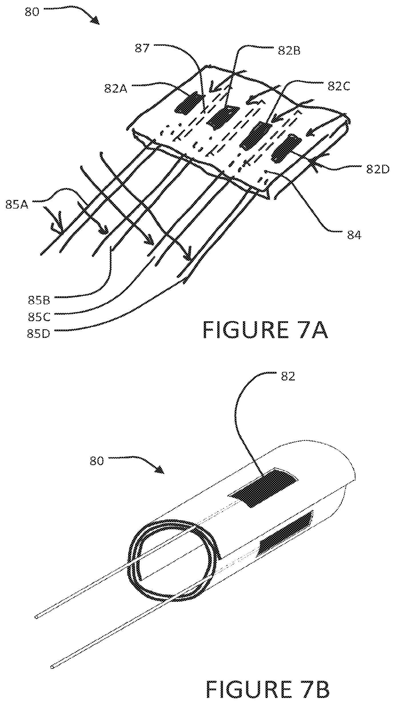
FIGS. 7A and 7B are perspective views showing an electrode structure having four electrodes respectively in a flat configuration and a rolled configuration. In the rolled configuration, the electrodes face radially outward.
FIGS. 7C and 7F are views showing plan views of unrolled electrode structures having electrodes that may be used in bipolar pairs (among other electrical configurations). FIGS. 7D and 7E show example ways for pairing the electrodes of the electrode structure of FIG. 7C.
FIG. 7G is a perspective view showing an electrode structure having four rows of electrodes in a rolled configuration in which the electrode structure is curled up within an apertured insertion tube.
FIG. 7H is a cross section through a blood vessel within which an electrode structure according to another embodiment has been placed.
FIGS. 8A and 8B are schematic illustrations of the use of a structure comprising bi-polar electrodes to stimulate a nerve extending transversely to a blood vessel.
FIG. 8C is a schematic illustrations of the use of a structure comprising bi-polar electrodes to stimulate a nerve extending generally parallel to a blood vessel.
FIG. 9 is a cut away view of a person's neck.
FIG. 9A is a cut away view illustrating a minimally invasive transvascular nerve stimulation system installed in a person according to an embodiment wherein an electrode structure is disposed in the person's internal jugular vein in the neck or upper chest region.
FIGS. 10A and 10B illustrate the anatomy of selected nerves and blood vessels in a person's neck and upper torso.
FIG. 11 is a cut away view illustrating a minimally invasive transvascular nerve stimulation system installed in a person according to an embodiment wherein electrode structures are disposed in one or both of the person's superior vena cava and left subclavian vein.
FIG. 12 is a cut away view illustrating a minimally invasive transvascular nerve stimulation system installed in a person according to an embodiment wherein control signals are transmitted wirelessly to cause stimulation signals to be delivered at electrode structures.
DESCRIPTION
Throughout the following description, specific details are set forth in order to provide a more thorough understanding of the invention. However, the invention may be practiced without these particulars. In other instances, well known elements have not been shown or described in detail to avoid unnecessarily obscuring the invention. Accordingly, the specification and drawings are to be regarded in an illustrative, rather than a restrictive, sense.
This invention relates to transvascular stimulation of nerves. In transvascular stimulation, suitable arrangements of one or more electrodes are positioned in a blood vessel that passes close to a nerve to be stimulated. Electrical currents pass from the electrodes through a wall of the blood vessel to stimulate the nerve.
FIG. 1 shows three nerves, N1, N2 and N3 that pass nearby a blood vessel V having a wall W defining a lumen L. FIG. 1 is illustrative and not intended to represent any specific blood vessel or nerves. FIG. 1 represents any suitable one of the various places in the body where nerves pass nearby to veins or arteries. Nerves N1 and N2 extend roughly parallel to blood vessel V and nerve N3 extends generally transversely to blood vessel V, at least in their parts depicted in FIG. 1. Nerve N1 is closer to blood vessel V than nerve N2.
FIG. 2 illustrates schematically the use of an electrode structure 10 inserted into lumen L of blood vessel V to stimulate nerve N1. Electrode structure 10 comprises an electrode 12, an electrically-insulating backing layer 14 and a means 15 for holding electrode 12 and backing layer 14 in place against the inner wall of blood vessel V. Electrode 12 may be attached to backing layer 14. This is not mandatory, however. It is sufficient that electrode 12 can be held against or at least in close proximity to the wall W of the blood vessel and that backing layer 14 covers the side of electrode 12 facing into lumen L. Various example structures that may be used as means 15 are described below. Electrode structures which provide electrodes backed by electrically-insulating barriers as illustrated generally in FIG. 2 may be provided in a variety of ways.
Electrode 12 is connected to a signal generator 18 by a suitable lead 17. Signal generator 18 supplies electrical current to electrode 12 by way of lead 17. Signal generator 18 may be implanted or external to the body. Signal generator 18 may, for example, comprise an implantable pulse generator (IPG).
In some embodiments electrode structure 10 includes a circuit (not shown) for applying signals to one or more electrodes 12 and a battery, system for receiving power wirelessly or another supply of electrical power. In such embodiments, signal generator 18 may deliver control signals which cause the circuit to apply stimulation signals to electrode 12 by way of a suitable wireless link technology. The wireless link may provide communication of the control signals between a small transmitter associated with signal generator 18 and a small receiver associated with electrode structure 10. With suitable miniature circuitry, it may be possible to provide a signal generator 18 that is co-located in a sufficiently large blood vessel with electrode structure 10. The signal generator 18 may, for example, comprise a thin electronic circuit embedded within backing sheet 14.
Electrode 12 serves as a source or as a sink for electrical current. Depending upon the nature of the electrical signals generated by signal generator 18 electrode 12 may serve as a current source at some times and as a current sink at other times. Another electrode or group of electrodes (not shown in FIG. 2) in contact with the patient serves to complete an electrical circuit. The other electrode or group of electrodes may be incorporated in electrode structure 10 (as is usually preferable) or may be separate.
Electrically-insulating backing layer 14 presents a high-impedance to the flow of electrical current and therefore reduces the amount of current flow through the blood in blood vessel V. It is not mandatory that layer 14 have an extremely high electrical resistance. It is sufficient if layer 14 has a resistance to the flow of electricity through layer 14 that is significantly greater than that presented by the flood in blood vessel V. Blood typically has a resistivity of about 120 to 190 .OMEGA.cm. In example embodiments, the blood in a blood vessel may provide an electrical resistance between closely-spaced electrical contacts that is inversely proportional to the dimensions of the lumen of the blood vessel. In large blood vessels the longitudinal electrical resistance between reasonable closely-spaced contacts can be a few tens of ohms for example. Layer 14 preferably provides an electrical resistance of at least a few hundred ohms, preferably a few kilo ohms or more to the flow of electrical current through the thickness of layer 14. Layer 14 could have electrically conductive members such as leads and the like embedded within it or electrically-conductive on its inner surface and still be considered to be `electrically-insulating`.
By making layer 14 of a suitable material such as silicone rubber elastomer, a biocompatible plastic, or another biocompatible insulating material it is easily possible to provide a backing layer 14 having a suitable resistance to the flow of electrical current. FIG. 2 illustrates how the presence of backing layer 14 directs the electric field E (illustrated schematically in FIG. 2 by lines of equipotential) outwardly from blood vessel V.
In FIG. 2, the delivery of electrical stimulation to nerve N1 is enhanced by: Locating electrode 12 against the internal wall of blood vessel V at a location close to nerve N1; Providing an electrode 12 having a relatively large contact surface that can achieve a large contact area with the inner wall of blood vessel V; Curving the contact surface of electrode 12 to roughly match the curvature of the inner face of blood vessel V; Providing electrically-insulating backing sheet 14. With these features, a significantly lower stimulation intensity is required to stimulate target nerve N1 than would be the case for wire electrodes located in lumen L in contact with the blood in lumen L. Additionally, selectivity for a nerve of interest is improved. Advantageously, electrodes 12 have active surface areas in the range of about 1/2 mm.sup.2 to about 5 mm.sup.2. In some embodiments, each electrode has an active surface area on the order of 2 mm.sup.2.
Electrode structure 10 may be introduced into blood vessel V in a minimally-invasive, safe way. Blood vessel V may be a relatively large blood vessel that courses in the vicinity of the target nerve N1. In some embodiments, electrode structure 10 comprises a flexible multi-contact electrode carrier sheet (ECS) of suitable dimensions. The sheet may be tightly coiled prior to its insertion into blood vessel V. Once within blood vessel V the sheet may be allowed to unwind so as to bring electrode 12 into contact with wall W of blood vessel V.
An electrode structure may support multiple electrodes. FIG. 3 shows an example electrode structure 20 which supports a number of electrodes including electrodes 22A, 22B, 22C and 22D (collectively electrodes 22). Other electrodes out of the plane of FIG. 3 may also be present. In the illustrated embodiment, electrodes 22A, 22B, 22C and 22D are circumferentially spaced approximately equally around the perimeter of the inside wall of blood vessel V. Each electrode 22 is insulated from the lumen of blood vessel V by a thin flexible insulating sheet 24 (individually identified as 24A, 24B, 24C and 24D). Each of the insulating sheets 24 is conformally disposed against the internal wall of blood vessel V. In alternative embodiments, two or more electrodes are disposed on a common insulating sheet. Insulating sheets 24 may be joined together or may be different parts of a continuous sheet.
E1, E2, E3 and E4 illustrate the areas corresponding to electrodes 24A through 24D in which the electrical field associated with current flow at the corresponding electrode is strong enough to stimulate a nerve. Increasing the strength of the signal (e.g. a stimulation pulse) at an electrode increases the affected area (as indicated by the larger dotted regions).
FIG. 3 shows two nerves N4 and N5. It can be seen that a stimulation signal from electrode 22A can stimulate nerve N4. A stimulation signal from electrode 22B can stimulate nerve N5. The arrangement of blood vessel V and nerves N4 and N5 is like the arrangement of the internal jugular vein and the phrenic and vagus nerves in the neck region of a person. With an arrangement as shown in FIG. 3, a target phrenic nerve at the location of N4 can be preferentially stimulated by electrode 22A due to greater proximity of electrode 22A and also due to the shape of the area E1 affected by electrode 22A. The vagus nerve at location N5 is usually approximately diametrically opposite from electrode 22A and is not affected by signals delivered at normal levels at electrode 22A. The vagus nerve is, however, affected by signals delivered at electrode 22C.
The phrenic nerve and vagus nerve in adult humans are each typically about 2 mm in diameter. The lumen of the internal jugular vein in adult humans is typically in the range of about 10 mm to 20 mm in diameter. The distance from the phrenic nerve to the internal jugular vein and the distance from the vagus nerve to the internal jugular vein are each typically in the range of about 2 mm to about 10 mm. Generally the phrenic nerve and vagus nerve are on opposite sides of the internal jugular vein so that they are roughly 15 mm to 30 mm apart from one another. This arrangement facilitates the ability to perform transvascular stimulation of only the vagus nerve or only the phrenic nerve without stimulating the other nerve. A system according to some embodiments stimulates the phrenic nerve or vagus nerve only. A system according to other embodiments selectively stimulates either or both of the phrenic and vagus nerves from an electrode structure located in the internal jugular vein.
In many cases, nerves comprise a plurality of fascicles. For example, in the example illustrated in FIG. 3, the phrenic nerve N4 is composed of three phrenic fascicles PF1, PF2, and PF3. These phrenic fascicles may be selectively recruited by progressive levels of stimulation current at electrode 22A. At lower stimulation levels, only PF1 is recruited. At higher levels PF1 and PF2 are both recruited. At still higher levels, all of PF1, PF2 and PF3 are recruited. In FIG. 3, the vagus nerve N5 is composed of two vagus fascicles VF1, and VF2 that may be selectively recruited by progressive levels of stimulation current at electrode 22C. At lower stimulation levels only VF1 is recruited. At higher stimulation levels both VF1 and VF2 are recruited.
It is desirable that an electrode structure provide a minimum obstruction to the flow of blood in lumen L of a blood vessel V. Therefore, electrode structures are preferably thin in comparison to the inner diameter of blood vessel V. In some embodiments, a structure that supports electrodes and insulating backing sheets gently urges the electrodes and insulating backing sheets radially outward in lumen L so as to leave an open passage for blood flow past the electrode structure. To prevent the disruption or blockage of blood flow in a blood vessel, the cross-sectional area of an intravascular electrode structure should not exceed a certain fraction of the cross-sectional area of the lumen of the blood vessel. A round blood vessel with an internal diameter of 10 mm has a cross-sectional area of approximately 75 mm.sup.2. The circumference of the electrode structure when expanded in the blood vessel should preferably not be greater than about 10.times..pi. mm, (approximately 30 mm). If the thickness of an electrode structure is between about 0.3 and 0.5 mm then the cross-sectional area of the electrode structure will be about 10 mm.sup.2 to 15 mm.sup.2, which represents less than 20% of the lumen of the vessel.
FIGS. 4A, 4B and 4C show an electrode structure 30 according to an example embodiment. Electrode structure 30 comprises a plurality of electrodes 32 disposed on a flexible electrically-insulating sheet 34. Electrode structure is initially introduced into a blood vessel V tightly curled up around an expandable stent 35 inside an introducer tube 36. Stent 35 may, for example, comprise an expandable wire stent. A variety of suitable expandable wire stents is available from medical devices manufacturers.
Electrode structure 30 is guided to a desired location in a blood vessel V inside introducer tube 36. At the desired location, introducer tube 36 is retracted to allow electrically-insulating sheet 34 to begin to unroll as shown in FIG. 4B. Stent 35 is then expanded in order to further unroll electrically-insulating sheet 34 and to urge electrically insulating sheet 34 and the electrodes 32 carried on electrically-insulating sheet 34 against the inner wall of blood vessel V as shown in FIG. 4C.
In the illustrated embodiment, stent 35 is attached to sheet 34 at a point, row of points or line 37. Stent 35 is left in place to retain electrodes 32 and sheet 34.
Stent 35 may comprise any suitable type of expandable stent. A wide range of such stents are known. Stent 35 is expanded in a manner appropriate to the stent. For example, in some embodiments a balloon is placed inside the stent and the stent is expanded by inflating the balloon. The balloon may be withdrawn after the stent has been expanded.
FIGS. 5A, 5B and 5C illustrate an electrode structure 40 which is similar to electrode structure 30 except that it has electrode 42 supported on a flexible sheet 44 and an engagement mechanism 47 which allows opposed edges portions 44A and 44B of flexible sheet 44 to be locked together when flexible sheet 44 has been opened within the lumen L of blood vessel V. The locking together of edge portions 44A and 44B holds flexible sheet 44 in an expanded configuration with electrodes 42 contacting the inner surface of wall W. Electrode structure 40 does not have a stent inside flexible sheet 44 (although a stent could optionally be added to provide further support for sheet 44). Sheet 44 may be made so that it has a tendency to unroll toward a configuration that is less tightly-rolled than shown in either of FIG. 5A or 5B. This tendency will bias sheet 44 to open into the configuration of FIG. 5B when removed from insertion tube 46 and will help to hold sheet 44 in place inside blood vessel V.
In the illustrated embodiment, mechanism 47 comprises mating sets of ridges 47A and 47B that extend longitudinally respectively along edge portions 44A and 44B. Ridges 47A and 47B are on opposing major surfaces of sheet 44 so that they can contact one another when sheet 44 is sufficiently unrolled. As shown in FIG. 5B, ridges 47A and 47B interlock when sheet 44 is unrolled as fully as the dimension of blood vessel V will permit. Mechanism 47 thus serves to retain sheet 44 and electrodes 42 snugly against the inside of wall W and prevent sheet 44 from curling inwardly or moving away from the wall W.
In preferred embodiments, mechanism 47 permits engagement of edge portions 44A and 44B in a range of degrees of overlap. Thus, mechanism 47 allows engagement of edge portions 44A and 44B when sheet 44 has been expanded against the inner wall of blood vessels having sizes within a given range of different sizes.
Alternative engagement mechanisms 47 are possible. For example, in some embodiments, a biocompatible adhesive is introduced between edge portions 44A and 44B. In other embodiments, ridges or other interlocking features and a biocompatible glue are both used.
An electrode structure 40 may be placed in a desired location by introducing and sliding the electrode structure along a blood vessel to a desired location; at the desired location, sliding electrode structure 40 out of tube 46; if electrode structure 40 is partially or entirely self-unwinding, allowing electrode structure 40 to unwind; and, if necessary, inflating a balloon 49 to fully expand electrode structure 40 and/or engage engagement mechanism 47. Introducing the electrode structure may comprise cannulating the blood vessel and introducing the electrode structure at the cannulation site.
FIG. 5C illustrates a method for removing or relocating an electrode structure 40. Electrode structure 40 comprises a tab 48 or other projection that is attached to sheet 44 near or at an inside edge thereof and is graspable from within lumen L. A tool 50 is inserted into lumen L and has jaws 51 operable to grasp tab 48. At position 50A jaws 51 of tool 50 are opened to receive tab 48. At position 50B, jaws 51 have been operated to grasp tab 48. At position 50C tool 50 has been moved toward the center of lumen L and tool 50 has thereby peeled the inner edge of sheet 44 away from wall W. Tool 50 may be rotated about its axis to roll electrode structure 40 into a smaller configuration. Electrode structure 40 may then be moved along blood vessel 44 to a new position; or pulled into an insertion tube for safe removal from blood vessel V.
FIGS. 6 and 6A show an electrode structure 70 that includes a rolled, flexible electrically-insulating sheet 74 carrying electrodes 72. Sheet 74 may be opened by partial unrolling within a blood vessel V. A tabular retainer 73 may then be inserted to retain sheet 74 and electrodes 72 in place against a wall of the blood vessel. In cases where electrode structure 70 is to be inserted into the blood vessel through an incision that is smaller than the lumen of the blood vessel then tubular retainer 73 may be expandable so that it can be introduced through the opening and then expanded to a size suitable for retaining sheet 74 and electrodes 72.
Retainer 73 has a diameter selected such that, when placed inside sheet 74, it will retain sheet 74 and electrodes 72 in close apposition to the inside wall of the blood vessel for as long as required. The outside diameter of retainer 73 is chosen to closely match the inner diameter of the blood vessel V minus twice the thickness of sheet 74. For example, for a blood vessel with an inside diameter of 10 mm and an electrode structure 70 with sheet thickness of 1/2 mm, the outside diameter of retainer 73 should be approximately 10 mm-2.times.1/2 mm=9 mm. Retainers 73 in a range of diameters may be provided to allow a surgeon to select and insert the best size. In typical blood vessels having inner diameters of 10 mm or more, the length of retainer 73 should be at least about twice its diameter to ensure that retainer 73 will not tilt inside the blood vessel. The wall thickness of retainer 73 may be fairly small, for example, up to about 0.3 mm or so. Retainer 73 may be made of a suitable material such as a biocompatible metal (e.g. stainless steel or titanium) or a high-strength biocompatible polymer.
Wires 75 carry signals from a signal generator to electrodes 72. In an alternative embodiment, a signal generator is integrated with electrode structure 70. Such as signal generator may be controlled to issue stimulation pulses in response to control signals provided by way of a suitable wireless link.
FIGS. 7A to 7G show examples of electrode structures. Electrode structure 80 of FIG. 7A has four electrodes 82 (individually 82A to 82D) supported on a major face 81 of a flexible insulating sheet 84. Insulated leads 85 connect electrodes 82 to a signal generator (not shown in FIG. 7A). Sheet 84 may comprise a flexible layer of silicone for example. Electrodes 82 and electrode leads 85 may be of any suitable shape and material; e.g., stainless steel or platinum-iridium multi-stranded wire electrodes with Teflon.TM. coated wire leads.
An electrode structure 80 may be fabricated, for example, by connecting suitable electrodes to coated wire leads and then embedding the electrodes and leads in a layer of silicone such that the electrodes are exposed on one major face of the silicone layer but not the other.
Electrode structure 80 may be used to stimulate nerves by inserting electrode structure 80 into a blood vessel with electrodes 82 facing outwardly; and connecting any one electrode to the negative output of a standard constant-current (preferably) or constant-voltage nerve stimulator (cathodic stimulation) with respect to a remote reference electrode. Alternatively, any two electrodes 82 can be selected as anode and cathode.
Electrode structure 80 is similar to a nerve cuff but `inside out`. Each electrode preferentially stimulates a sector of tissue that radiates outwardly from a blood vessel V and spans a limited angle. For example, in an electrode structure having four electrodes disposed approximately every 90 degrees around the circumference of a blood vessel, the volume of tissue affected by each electrode may span approximately 90 degrees (see FIG. 3 for example).
A further improvement in angular selectivity may be obtained by providing longitudinal ridges on the outer major surface of electrode structure 80. The ridges enhance the electrical separation between circumferentially-adjacent electrodes 82. The ridges may be similar to the ridges described in Hoffer et al. U.S. Pat. No. 5,824,027 entitled NERVE CUFF HAVING ONE OR MORE ISOLATED CHAMBERS which is hereby incorporated herein by reference. Ridges 86 are shown schematically in FIG. 7A.
Optionally, sheet 84 may include geometrical complexities such as holes or protuberances to provide a better substrate for connective tissue adhesion and so increase the long-term mechanical stability and immobility of structure 80 inside a blood vessel.
FIG. 7B shows an electrode structure like electrode structure 80 wrapped into a tight spiral with electrodes facing out in preparation for insertion into a blood vessel.
FIG. 7C shows an electrode structure 90 according to another embodiment. Electrode structure 90 comprises a flexible sheet 94 that supports four pairs of electrodes 92. Sheet 94 may comprise a thin flexible silicone sheet, for example. Electrical leads 93 are provided to connect corresponding electrodes 92 to a signal source. Electrodes and electrode leads may be of any suitable shape and material; e.g., stainless steel or platinum-iridium multi-stranded wire with Teflon.TM. coated leads. In the illustrated embodiment, electrode contact surfaces are exposed through electrode windows in winch insulation of the leads is not present. Electrodes 92A and 92E; 92B and 92F; 92C and 92G; and 92D and 92H may be paired, for example, as shown in FIG. 7D. As another example, electrodes 92A and 92B; 92C and 92D; 92E and 92F; and 92G and 92H may be paired as shown in FIG. 7E.
Electrode structure 90 may be applied to stimulate a nerve or nerves by inserting electrode structure 90 into a blood vessel with electrodes 92 facing outwardly; and connecting any two electrodes 92 to the negative and positive outputs of a standard constant-current or constant-voltage nerve stimulator. An effective mode of stimulation is to select a pair of electrodes that are aligned along a line that is generally parallel to the target nerve, such that the greatest potential difference during stimulation will be generated along the nerve axons in the target nerve. Since the target nerve and target blood vessel may not be strictly parallel to one another, it is useful to have multiple electrodes in an electrode structure from which the pair of electrodes that provide the greatest stimulation selectivity for a target nerve can be identified by trial and error.
FIG. 7F shows an electrode structure 90A that is like electrode structure 90 except that it includes ridges 91 of electrically-insulating material that extend between groups of electrodes 92.
FIG. 7G shows an electrode structure like electrode structure 90 prepared for insertion into a blood vessel. Electrode structure 90 is rolled up into a spiral and held by an outside retainer 95. Outside retainer 95 has relatively thin walls. For example, the wall thickness may be about 1/2 mm or less in some embodiments. Apertures 96 penetrate the wall of outside retainer 95 and allow flow of electrical currents. Apertures 96 could optionally be filled with electrically-conducting plugs.
At least one electrode 92 of electrode structure 90 is electrically exposed to the surroundings through an aperture 96. As the electrode structure is being advanced toward an intravascular target location (the target location may be determined in advance from an imaging survey study for each patient, and monitored with fluoroscopy during the ECS implant procedure), electrodes 92 are energized. Since at least some electrodes 92 are exposed by way of apertures 96 the target nerve will be stimulated when electrode structure 90 is close enough to the target nerve. An effect of stimulation of the target nerve can be watched for in order to determine when electrode structure has reached the vicinity of the target nerve. The response may be monitored to fine tune the position of electrode structure 90 in a blood vessel. Outside retainer 95 may be removed when electrode structure 90 is at the target location. Outside retainer 95 is tethered by a tether 97 so that it can be recovered after deployment of structure 90.
FIG. 7H shows structure 90 at its intended location in blood vessel V. Outer retainer 96 has been removed and the structure 90 has been allowed to unwind and deploy against the inside wall of blood vessel V. The width (circumferential dimension) of structure 90 is chosen to closely match the inside perimeter of blood vessel V at the target location. The inside dimension of the blood vessel V may have been previously determined from ultrasound imaging, balloon catheter, magnetic resonance imaging or other non-invasive or minimally-invasive imaging technique.
When electrode structure 90 is at its desired position for optimal stimulation of the target nerve, the outer retainer 95 is gently removed and withdrawn from the patient's body while structure 90 is kept in place, if needed, by means of a semi-rigid rod-like tool (not shown) that is temporarily used to stabilize structure 90 and prevent it from moving while outer retainer 95 is withdrawn. As the outer retainer 95 is withdrawn, structure 90 will naturally and rapidly unwrap toward its preferred enlarged-cylindrical (or near-planar in some embodiments) configuration and will stretch out against the inside wall of the blood vessel with electrodes 92 disposed outwardly in close contact to the blood vessel wall.
As noted above, the choice of electrodes to use to stimulate a target nerve can depend on the orientation of the target nerve relative to the blood vessel in which an electrode structure is deployed. Where a target nerve passes more or less at right angles to a blood vessel, it can be most efficient to stimulate the target nerve by passing electric current between two electrodes that are spaced apart circumferentially around the wall of the blood vessel. In such cases it may be desirable to provide elongated electrodes that extend generally parallel to the blood vessel (e.g. generally parallel to an axis of curvature of the electrode structure). Such elongated electrodes may be emulated by a row of smaller electrodes that are electrically connected together.
FIGS. 8A and 8B show a nerve N extending transversely to a blood vessel V. In the illustrated embodiment, the nerve extends generally at right angles to the blood vessel. An electrode structure 54 comprising first and second electrodes 55A and 55B (collectively electrodes 55) is located in lumen L of blood vessel V. Electrodes 55 are each close to or pressed against the inner face of wall W of blood vessel V. Electrode structure 54 may have additional electrodes as well as other features such as a structure for holding electrodes 54 in place however these are not shown in FIG. 8A or 8B for clarity. Electrodes 55A and 55B are spaced apart from one another in a circumferential direction around the periphery of blood vessel V. Electrodes 55 are ideally disposed in a plane in which nerve N lies and which intersects blood vessel V perpendicularly. Precise placement of the electrodes in such a configuration is not mandatory. Electrodes 55 are spaced apart in a direction that is generally along an axis of nerve N.
Each electrode 55 is protected against electrical contact with the blood in lumen L of blood vessel V by an insulating backing member 56. In the illustrated embodiment, backing members 56 comprise hollow insulating caps that may, for example, have the form of hollow hemispheres. An edge of each insulating cap contacts wall W of blood vessel V around the periphery of the corresponding electrode 55.
In this embodiment, electrodes 55 are connected in a bi-polar arrangement such that one electrode acts as a current source and the other acts as a current sink. It is not mandatory that the polarities of electrodes 55 always stay the same. For example, in some stimulation modes the polarities could be switched. In the illustrated embodiment, electrode 55A is connected as a cathode (negative) electrode while electrode 55B is connected as an anode (positive) electrode to a signal source (not shown in FIG. 8A or 8B). When a stimulation signal is applied between electrodes 55 an electric field is created. The electric field causes small electrical currents to flow between electrodes 55 by way of the surrounding tissues.
Since electrodes 55 are insulated from the lumen of blood vessel V, electric current flows out of the current source electrode 55A through wall W and surrounding tissues and returns to the current sink electrode 55B. The stimulation current flows longitudinally through the nerve N in the direction shown by arrows F. For stimulation pulses of sufficient duration and intensity, the nerve axons in target nerve N will generate action potentials that will be conducted along the stimulated axons in nerve N.
Where a target nerve tends generally parallel to a blood vessel it can be efficient to stimulate the target nerve by passing electric current between two electrodes that are spaced apart longitudinally along the wall of the blood vessel.
FIG. 8C shows a nerve N extending parallel to a blood vessel V. An electrode structure 88 having first and second electrodes 89A and 89B (collectively electrodes 89) is located inside blood vessel V with electrodes 89A and 89B close to, preferably against the inside of the wall W of blood vessel V. Electrode structure 88 may have additional electrodes as well as other features such as a structure for holding electrodes 89 in place however these are not shown in FIG. 8C for clarity. Electrodes 89A and 89B are spaced apart from one another in a longitudinal direction along blood vessel V. The electrodes are ideally disposed on a line extending parallel to an axis of the blood vessel although precise placement of the electrodes in such a configuration is not mandatory.
In this embodiment, electrodes 89A and 89B are connected in a bi-polar arrangement such that one electrode acts as a current source and the other acts as a current sink. It is not mandatory that the polarities of electrodes 89A and 89B always stay the same. For example, in some stimulation modes the polarities could be switched.
In the illustrated embodiment, electrode 89A is connected as a cathode (negative) electrode while electrode 89B is connected as an anode (positive) electrode to a signal source (not shown in FIG. 8C). Each electrode 89 is protected against electrical contact with the blood in lumen L of blood vessel V by an insulating backing member 87. In the illustrated embodiment, the backing members comprise hollow insulating caps that may, for example, have the form of hollow hemispheres. An edge of each insulating cap contacts the wall of blood vessel V around the periphery of the corresponding electrode 89.
Since electrodes 89 are electrically insulated from the blood in lumen L of blood vessel V, electric current flows out of the current source (e.g. cathode 89A), through wall W and eventually returns to the current sink (e.g. anode electrode 89B). This results in a stimulation current that flows longitudinally through nerve N in the direction shown by arrows F. For stimulation pulses of sufficient duration and intensity, the nerve axons in the target nerve will generate action potentials that will be conducted along the stimulated axons by nerve N.
Stimulating the phrenic nerves to regulate or cause breathing is an example application of electrode structures as described herein. The present invention provides a surgically simple, lower risk response to the need of stimulating the phrenic nerves to control the movement of the diaphragm and restore normal breathing rate in people who have lost control of diaphragm due to a central neurological lesion such as a high cervical spinal cord injury or disease, including quadriplegia; central alveolar hypoventilation; decreased day or night ventilatory drive (e.g. central sleep apnea, Ondine's Curse) or brain stem injury or disease. Phrenic nerves may be stimulated on an acute care or chronic basis.
The phrenic nerves provide the major nerve supply to the diaphragm. Each phrenic nerve contributes predominantly motor fibres solely to its hemidiaphragm. The passage taken by the right and left phrenic nerves through the thorax is different. This is largely due to the disposition of great vessels within the mediastinum. Occasionally, the phrenic nerve may be joined by an accessory phrenic nerve.
The phrenic nerve on both sides originates from the ventral rami of the third or fifth cervical nerves. The phrenic nerve passes inferiorly down the neck to the lateral border of scalenus anterior. Then, it passes medially across the border of scalenus anterior parallel to the internal jugular vein which lies inferomedially. At this point the phrenic nerve is deep to the prevertebral fascia, the transverse cervical artery and the suprascapular artery.
At the anterior, inferomedial margin of scalenus anterior and hence superficial to the second part of the right subclavian artery, the right phrenic nerve passes medially to cross the pleural cupola deep to the subclavian vein. More medially, it crosses the internal thoracic artery at approximately the level of the first costochondral junction.
Within the thorax the right phrenic nerve is in contact with mediastinal pleura laterally and medially, in succession from superior to inferior, the following venous structures; right brachiocephalic vein, superior vena cava, pericardium of the right atrium, inferior vena cava. From the level of the superior vena cava it is joined by the pericardiophrenic artery and both run inferiorly anterior to the lung root. The right phrenic nerve pierces the diaphragm in its tendinous portion just slightly lateral to the inferior vena caval foramen. It then forms three branches on the inferior surface of the diaphragm: anterior, lateral and posterior. These ramify out in a radial manner from the point of perforation to supply all but the periphery of the muscle.
At the anteroinferior medial margin of scalenus anterior, the left phrenic nerve crosses the first part of the left subclavian artery and then the internal thoracic artery sited slightly inferiorly. Passing inferiorly with the internal thoracic artery laterally, it lies deep to the left brachiocephalic vein and the left first costochondral joint. It receives a pericardiophrenic branch of the internal thoracic artery which stays with its distal course.
Within the thorax, the left phrenic nerve continues inferiorly and slightly laterally on the anterolateral aspect of the arch of the aorta, separated from the posterior right vagus nerve by the left superior intercostal vein. Then it descends anterior to the root of the left lung intermediate to fibrous pericardium medially and parietal pleura laterally. Finally, it curves inferiorly and anteriorly to reach the surface of the diaphragm which it pierces anterior to the central tendon and lateral to the pericardium. It then forms three branches on the inferior surface of the diaphragm: anterior, lateral and posterior. These ramify out in a radial manner from the point of perforation to supply all but the periphery of the muscle.
The accessory phrenic nerve on each side occurs in roughly 15-25% of people. It originates as a branch of the fifth cervical nerve which would otherwise pass to the subclavius. The accessory phrenic nerve begins lateral to the phrenic nerve in the neck and obliquely traverses the anterior surface of scalenus anterior as it descends. It joins the phrenic nerve at the root of the neck to descend to the diaphragm.
FIG. 9 shows the anatomy of the neck and, in particular, the relative locations of phrenic nerve (PhN), vagus nerve (VN) and internal jugular vein (IJV). Note that the IJV courses between the PhN and VN. The PhN merges with the IJV and the three structures run together distally at level of the clavicle (indicated by circle 99).
In one example embodiment illustrated in FIG. 9A, a minimally invasive nerve stimulation system (`MINS`) 100 comprising a flexible intravascular electrode array 101, for example, an electrode structure of one of the embodiments described above is permanently placed inside a target blood vessel V (in this example the left Internal Jugular Vein, IJV) in close proximity to a target nerve (in this example the left phrenic nerve PhN). One or more electrodes of the electrode array is disposed for selective stimulation of the PhN. Other electrodes are optionally disposed for selective stimulation of a second target nerve, in this example the left vagus nerve VN.
The electrode leads 104 from electrode array 101 emerge from the cannulated BV at the original venous penetration site, C, and then course subcutaneously to connectors 105 that connect to the header of an implanted pulse generator 102 that is surgically placed in a standard subcutaneous pocket. The pocket may be in the upper chest wall for example. FIG. 9 shows only one electrode array 101 on the left side of the neck.
In this embodiment, the implanted MINS 100 stimulates the left PhN to assist breathing by causing rhythmic inspiratory movements of the diaphragm muscle (not shown in FIG. 9). Another electrode array may additionally be implanted in a blood vessel on the right side of the patient's body. For example, another electrode array 101 may be implanted in the right internal jugular vein for selective stimulation of the right PhN and, optionally, also the right VN, if so desired. The additional electrode array may be connected to internal pulse generator 102 or to a second internal pulse generator (not shown in FIG. 9).
MINS 100 may be installed percutaneously using standard procedures for the installation of deep catheters, cannulas, leads or other intravascular device. Such procedures are described in the medical literature. Once an electrode array has been introduced to a location near the target location in the internal jugular vein then the position of the electrode array may be fine-tuned by applying low-current stimulation signals to one of more of the electrodes in electrode array 101 and observing the patient's breathing.
FIGS. 10A and 10B illustrate the anatomy of the neck and chest and in particular, the relative locations of the left and right phrenic nerves (PhN), vagus nerves (VN), internal jugular veins (IJV), brachiocephalic veins (BCV), subclavian veins (SCV) and superior vena cava (SVC). The PhNs run approximately perpendicular to and close to the BCVs in areas 107R and 107L near the IJV/BCV junctions.
Each PhN may have more that one branch. The branches may join together at variable locations ranging from the neck region to the chest region below the IJV/BCV junctions. In the latter case, branches of the PhN on either side of the body may course on opposite sides of the BCVs. Two branches of the right PhN are labeled PhN-1 and PhN-2 in FIG. 10B. The right PhN may include branches that course on either side of the SVC. The left and right PhN extend respectively to left and right hemi-diaphragms (HD).
FIG. 11 shows a MINS 110 having electrode structures 111L and 111R (collectively 111) located respectively in a patient's left SCV and SVC vessels near the left- and right-PhN respectively. Leads 112L and 112R (collectively 112) respectively connect the electrodes of left- and right-electrode structures 111L and 111R to a signal generator. In the illustrated embodiment, the signal generator comprises an implantable pulse generator (IPG) 115. Alternatively, as described above, some or all functions of pulse generator 115 may be provided by circuitry that is co-located with or integrated with one or both of electrode structures 111. In some embodiments, pulse generator 115 generates control signals that are transmitted by way of a wireless communication link to cause circuitry that is local to electrode structures 111 to apply stimulation pulses by way of electrodes on electrode structures 111.
The implantable pulse generator may be configured to deliver electrical pulses to electrodes of the left- and right electrode structures 111 more-or-less simultaneously so that the left- and right-hemidiaphragms are induced to undergo breathing motions in a synchronized manner. IPG 115 may, for example, apply bursts of stimulus pulses at a rate of about 12 or 13 bursts per minute. Each burst may, for example, comprise 20-40 current pulses delivered at a rate of 20 Hz or so and last roughly 1 to 2 seconds. Each burst induces signals in the phrenic nerve that cause the diaphragm to move to provide inspiration. Expiration occurs between bursts.
MINS 110 can be readily installed as shown in FIG. 11. Electrode structures 111R and 111L may both be introduced through the same intravascular insertion point C1 in the left SCV. In some embodiments, electrode structure 111L is installed first. In such embodiments, electrode structure 111L can be passed through the left SVC past electrode structure 111L (e.g. through a bore of electrode structure 111L) to its target location in the SVC. Flexible leadout cable 112R passes through electrode structure 111L. Both leadout cables 112 emerge from the SCV and course subcutaneously to a subcutaneous pocket area in the upper chest where the leadout cable connectors are connected to IPG 115.
Locating initial target positions for electrode structures 111 is facilitated because the SVC, heart and BCV can be readily visualized using available imaging techniques. It is known that the phrenic nerves pass tightly past the heart on each side. Therefore, target locations in the blood vessels within .+-.1 to 2 cm of the optimum positions for stimulating the phrenic nerves can be determined readily from images of the upper chest and lower neck.
The arrangement shown in FIG. 11 has the advantage that the distance from electrode structures 111 to the target nerves in these locations may be smaller, more uniform and more reproducible than for similar electrodes implanted in more proximal locations in the IJVs where the target PhNs run parallel to the IJVs, but at more variable distances (see FIG. 9, for example).
MINS 110 may be varied by leaving out one of electrode structures 111 and its associated cable 112. Such embodiments may be useful in acute care environments where it is necessary to provide breathing assistance using a simple quick procedure. Such embodiments may also be useful in chronic situations where stimulation of one hemi-diaphragm is sufficient. Where only one electrode structure 111 is implanted, the electrode structure may be at either the location of electrode structure 111R or the location of electrode structure 111L.
FIG. 12 shows a minimally-invasive nerve stimulation system 120 that is like MINS 110 of FIG. 11 but provides a wireless connection between an implantable pulse generator and circuits which deliver stimulation signals to electrodes. System 120 has two sets of intravascular electrodes 121A and 121B. In some embodiments, each set of electrodes comprises an electrode structure as described herein. Each set of electrodes 121A and 121B is connected by short flexible lead wires 123 to an associated RF receiver unit 124. RF receiver units receive wireless stimulation commands 125 from an implanted pulse generator 126 having an associated transmitter (which is built into implantable pulse generator 126 in the illustrated embodiment.
Each receiver unit 124 may comprise a hermetic package containing an antenna and circuitry to decode command signals and deliver stimulation pulses to the electrodes of the corresponding electrode array 121. Each receiver arm may be attached to an autonomous stent-like structure for safe, permanent and stable installation in a blood vessel near the associated electrode array 121. The receiver units may be powered by the RF signal received from implantable pulse generator 126. In such cases, the receiver units do not require internal batteries.
Implantable pulse generator 126 may contain batteries or another source of electrical energy, control circuitry and transmitter antennas to communicate with receiver units 124 and with an external programmer (not shown) that allows a therapist to program the implanted system.
In some embodiments, an implantable pulse generator or other signal source may have a primary battery or a rechargeable battery that can be periodically recharged through the patient's skin. In either case, it is desirable that the battery or other source of electrical power have an expected life span such that it will not require replacement for a reasonable period such as at least about 3 to 5 years.
Methods of stimulating the phrenic nerves, as described herein can have the advantages that: electrodes do not come into contact with the delicate phrenic nerves; there is no implanted structure that interferes with movement of the diaphragm; the system may be implanted and self-contained such that no wires cross the skin; access to both the right and left phrenic nerves can be provided through a single point of entry; a control system, such as an implantable pulse generator may be placed in reasonably close proximity to an electrode structure so as to facilitate wireless control over the delivery of stimulation pulses at the electrode structure by the implantable pulse generator.
The applications of the apparatus and methods described herein are not limited to phrenic and vagus nerves. The apparatus and methods described herein may be applied to provide surgically simple, low risk solutions for stimulating a wide range of peripheral or cranial nerves. For example, the methods and apparatus may be applied to stimulate the obturator nerve in the hip/groin area of the trigeminal nerve in the head.
The apparatus and methods may be applied to treatment of a wide variety of disorders such as pain of peripheral or craniofacial origin, sensory deficits, paralysis or paresis of central origin, autonomic disorders, and generally any medical condition that can be treated or alleviated using neuromodulation by electrical stimulation of a nerve that is in close proximity to a larger blood vessel into which a flexible multi-channel electrode array can be deployed.
Advantageously, implantation of electrode structures in blood vessels is reversible and does not require surgical intervention directly involving the target nerves.
In some embodiments, signal generator 115 has sensors that sense a condition of the patient and adjust stimulation of the phrenic nerve based on input from the sensors. The sensors may detect things such as one or more of: whether the patient is speaking or preparing to speak; whether the patient is lying down or sitting or standing; whether the patient is awake or asleep; blood oxygen concentration; blood CO.sub.2 concentration; etc. In response to the sensor signals, the signal generator may adapt the pattern or rate of breathing. For example: Breathing could automatically suppressed when a sensor signal indicates that the patient is attempting to speak. A breathing rate could be increased during periods of increased physical activity or low blood oxygen concentration. A breathing rate could be decreased or regularized during periods of relaxation or sleep. On-demand breathing stimulation could be provided in response to the detection of the onset of irregular breathing during sleep.
The sensors may be built into the signal generator. For example, the signal generator may include: accelerometers and processor logic configured to determine from outputs of the accelerometers whether the patient's motions indicate that the patient is awake or asleep; an inclinometer or accelerometer and processor logic configured to determine from one or more outputs of the inclinometer of accelerometer whether the patient is lying or upright.
Other sensors may be implanted. For example, in some embodiments, a blood chemistry sensor such as a blood oxygen sensor and/or a blood CO.sub.2 sensor is implanted at a suitable location in the patient. The blood oxygen monitor may be mounted on an electrode structure 111 for example. Other sensors may sense signals in the patient's nerves.
Where a component (e.g. an electrode, signal generator, lead, stent, assembly, device, antenna, circuit, etc.) is referred to above, unless otherwise indicated, reference to that component (including a reference to a "means") should be interpreted as including as equivalents of that component any component which performs the function of the described component (i.e., that is functionally equivalent), including components which are not structurally equivalent to the disclosed structure which performs the function in the illustrated exemplary embodiments of the invention.
As will be apparent to those skilled in the art in the light of the foregoing disclosure, many alterations and modifications are possible in the practice of this invention without departing from the spirit or scope thereof. For example, electrodes on an electrode structure may be arranged to provide unipolar, bipolar, tripolar or balanced tripolar electrode arrangements or combinations thereof. The example embodiments described herein include various features such as different geometries for insulating backing sheets, different arrangements of electrodes, different control arrangements, and the like. These features may be mixed and matched (i.e. combined on additional combinations) in other embodiments of the invention. Accordingly, the scope of the invention is to be construed in accordance with the substance defined by the following claims.
* * * * *
D00000
D00001
D00002
D00003
D00004
D00005
D00006
D00007
D00008
D00009
D00010
D00011
D00012

D00013

D00014

D00015

D00016

XML
uspto.report is an independent third-party trademark research tool that is not affiliated, endorsed, or sponsored by the United States Patent and Trademark Office (USPTO) or any other governmental organization. The information provided by uspto.report is based on publicly available data at the time of writing and is intended for informational purposes only.
While we strive to provide accurate and up-to-date information, we do not guarantee the accuracy, completeness, reliability, or suitability of the information displayed on this site. The use of this site is at your own risk. Any reliance you place on such information is therefore strictly at your own risk.
All official trademark data, including owner information, should be verified by visiting the official USPTO website at www.uspto.gov. This site is not intended to replace professional legal advice and should not be used as a substitute for consulting with a legal professional who is knowledgeable about trademark law.