Removable leg walker
Iglesias , et al. December 15, 2
U.S. patent number 10,863,791 [Application Number 13/441,552] was granted by the patent office on 2020-12-15 for removable leg walker. This patent grant is currently assigned to Ovation Medical. The grantee listed for this patent is Tracy E. Grim, Joseph Michael Iglesias. Invention is credited to Tracy E. Grim, Joseph Michael Iglesias.
| United States Patent | 10,863,791 |
| Iglesias , et al. | December 15, 2020 |
Removable leg walker
Abstract
An orthopedic walking boot for a user includes an outer sole having a substantially continuously curved lateral profile bottom walking surface, wherein a radius of curvature of the lateral walking surface varies between 10 mm and infinity, and an upper portion arranged with the outer sole to support a lower portion of the user's leg.
| Inventors: | Iglesias; Joseph Michael (Agoura Hills, CA), Grim; Tracy E. (Agoura Hills, CA) | ||||||||||
|---|---|---|---|---|---|---|---|---|---|---|---|
| Applicant: |
|
||||||||||
| Assignee: | Ovation Medical (Agoura Hills,
CA) |
||||||||||
| Family ID: | 1000005241895 | ||||||||||
| Appl. No.: | 13/441,552 | ||||||||||
| Filed: | April 6, 2012 |
Prior Publication Data
| Document Identifier | Publication Date | |
|---|---|---|
| US 20120255204 A1 | Oct 11, 2012 | |
Related U.S. Patent Documents
| Application Number | Filing Date | Patent Number | Issue Date | ||
|---|---|---|---|---|---|
| 61472946 | Apr 7, 2011 | ||||
| Current U.S. Class: | 1/1 |
| Current CPC Class: | A43B 13/145 (20130101); A43B 13/143 (20130101) |
| Current International Class: | A43B 13/14 (20060101) |
| Field of Search: | ;36/140,155,110,103 ;602/23,61,65 |
References Cited [Referenced By]
U.S. Patent Documents
| 143537 | October 1873 | Silberschmidt |
| 1472415 | October 1923 | Haggerty |
| 2643468 | June 1953 | Gottschalk |
| 2959169 | November 1960 | Bless |
| 3464126 | September 1969 | Sarkissian |
| 3504668 | April 1970 | Boudon |
| 3661151 | May 1972 | Schoenbrun et al. |
| 3665619 | May 1972 | Gray |
| 3792537 | February 1974 | Plank et al. |
| 3805773 | April 1974 | Sichau |
| 3814088 | June 1974 | Raymond |
| 3955565 | May 1976 | Johnson |
| 3976059 | August 1976 | Lonardo |
| 4005704 | February 1977 | Stohr et al. |
| 4053995 | October 1977 | Shein |
| 4057056 | November 1977 | Payton |
| 4094312 | June 1978 | Whyte |
| 4100686 | July 1978 | Sgarlato et al. |
| 4100918 | July 1978 | Glancy |
| 4184273 | January 1980 | Boyer et al. |
| 4188735 | February 1980 | Hahn |
| 4215491 | August 1980 | Giannetti |
| 4217706 | August 1980 | Vartanian |
| 4265033 | May 1981 | Pois |
| 4268931 | May 1981 | Salomon |
| 4393866 | July 1983 | Finnieston |
| 4446856 | May 1984 | Jordan |
| 4454871 | June 1984 | Mann et al. |
| 4494536 | January 1985 | Latenser |
| 4497070 | February 1985 | Cho |
| 4505269 | March 1985 | Davies et al. |
| 4510927 | April 1985 | Peters |
| 4550721 | November 1985 | Michel |
| 4556054 | December 1985 | Paulseth |
| 4559934 | December 1985 | Philipp |
| 4567678 | February 1986 | Morgan et al. |
| 4572169 | February 1986 | Mauldin et al. |
| 4587962 | May 1986 | Greene et al. |
| 4590932 | May 1986 | Wilkerson |
| 4624247 | November 1986 | Ford |
| 4628945 | December 1986 | Johnson, Jr. |
| 4665904 | May 1987 | Lerman |
| 4771768 | September 1988 | Crispin |
| 4805601 | February 1989 | Eischen, Sr. |
| 4825856 | May 1989 | Nelson |
| 4844094 | July 1989 | Grim |
| 4862900 | September 1989 | Hefele |
| 4872273 | October 1989 | Smeed |
| 4879822 | November 1989 | Hayes |
| 4919118 | April 1990 | Morris |
| 4941271 | July 1990 | Lakic |
| 4947838 | August 1990 | Giannetti |
| 4964402 | October 1990 | Grim et al. |
| 4974583 | December 1990 | Freitas |
| 4982733 | January 1991 | Broadhurst et al. |
| 4989349 | February 1991 | Ellis, III |
| 4999932 | March 1991 | Grim |
| 5020523 | June 1991 | Bodine |
| 5078128 | January 1992 | Grim et al. |
| 5086761 | February 1992 | Ingram |
| 5088478 | February 1992 | Grim |
| 5088479 | February 1992 | Detoro |
| 5088481 | February 1992 | Darby |
| 5092321 | March 1992 | Spademan |
| 5125400 | June 1992 | Johnson, Jr. |
| 5154695 | October 1992 | Farris et al. |
| 5176623 | January 1993 | Stetman et al. |
| 5197942 | March 1993 | Brady |
| 5213564 | May 1993 | Johnson, Jr. et al. |
| 5219324 | June 1993 | Hall |
| 5226245 | July 1993 | Lamont |
| 5226875 | July 1993 | Johnson |
| 5233767 | August 1993 | Kramer |
| 5242379 | September 1993 | Harris et al. |
| 5277695 | January 1994 | Johnson, Jr. et al. |
| RE34661 | July 1994 | Grim |
| 5329705 | July 1994 | Grim et al. |
| 5330419 | July 1994 | Toronto |
| 5334135 | August 1994 | Grim et al. |
| 5352189 | October 1994 | Schumann et al. |
| 5353525 | October 1994 | Grim |
| 5367789 | November 1994 | Lamont |
| 5368551 | November 1994 | Zuckerman |
| 5370133 | December 1994 | Darby et al. |
| 5370604 | December 1994 | Bernardoni |
| 5378223 | January 1995 | Grim et al. |
| 5383290 | January 1995 | Grim |
| 5384970 | January 1995 | Melton |
| 5392534 | February 1995 | Grim |
| 5399152 | March 1995 | Habermeyer et al. |
| 5399155 | March 1995 | Strassburg et al. |
| 5407421 | April 1995 | Goldsmith |
| 5425701 | June 1995 | Oster et al. |
| 5426872 | June 1995 | Hayes |
| 5429588 | July 1995 | Young et al. |
| 5441015 | August 1995 | Farley |
| 5445602 | August 1995 | Grim et al. |
| 5460599 | October 1995 | Davis et al. |
| 5464385 | November 1995 | Grim |
| 5483757 | January 1996 | Frykberg |
| 5496263 | March 1996 | Fuller, II et al. |
| 5503622 | April 1996 | Wehr |
| 5507720 | April 1996 | Lampropoulos |
| 5526586 | June 1996 | Foscaro |
| 5527269 | June 1996 | Reithofer |
| 5551950 | September 1996 | Oppen |
| 5554104 | September 1996 | Grim |
| 5571077 | November 1996 | Klearman et al. |
| 5577998 | November 1996 | Johnson, Jr. et al. |
| 5582579 | December 1996 | Chism et al. |
| 5609570 | March 1997 | Lamont |
| 5617650 | April 1997 | Grim |
| 5620411 | April 1997 | Schumann et al. |
| 5632723 | May 1997 | Grim |
| 5641322 | June 1997 | Silver et al. |
| 5675839 | October 1997 | Gordon et al. |
| 5720715 | February 1998 | Eriksson |
| 5761834 | June 1998 | Grim et al. |
| 5762622 | June 1998 | Lamont |
| 5772619 | June 1998 | Corbett |
| 5776090 | July 1998 | Bergmann et al. |
| 5799659 | September 1998 | Stano |
| 5823981 | October 1998 | Grim et al. |
| 5827210 | October 1998 | Antar et al. |
| 5827211 | October 1998 | Sellinger |
| 5833639 | November 1998 | Nune et al. |
| 5836902 | November 1998 | Gray |
| 5853381 | December 1998 | Stevenson et al. |
| 5857987 | January 1999 | Habermeyer |
| 5865166 | February 1999 | Fitzpatrick et al. |
| 5868690 | February 1999 | Eischen, Sr. |
| 5887591 | March 1999 | Powell et al. |
| 5891073 | April 1999 | Deirmendjian et al. |
| 5897515 | April 1999 | Willner et al. |
| 5897520 | April 1999 | Gerig |
| 5902259 | May 1999 | Wilkerson |
| 5913841 | June 1999 | Lamont |
| 5925010 | July 1999 | Caprio, Jr. |
| 5951504 | September 1999 | Iglesias et al. |
| 5954075 | September 1999 | Gilmour |
| 5961477 | October 1999 | Turtzo |
| 5971946 | October 1999 | Quinn et al. |
| 5980475 | November 1999 | Gibbons |
| 5993404 | November 1999 | Mc Niel |
| 6019741 | February 2000 | Prieskorn |
| 6021780 | February 2000 | Darby |
| 6024712 | February 2000 | Iglesia et al. |
| 6027468 | February 2000 | Pick |
| 6044578 | April 2000 | Kelz |
| 6056712 | May 2000 | Grim |
| 6126625 | October 2000 | Lundberg |
| 6146349 | November 2000 | Rothschild et al. |
| 6154983 | December 2000 | Austin |
| 6155998 | December 2000 | Gilmour |
| 6189172 | February 2001 | Baek |
| 6228044 | May 2001 | Jensen et al. |
| 6247250 | June 2001 | Hauser |
| 6267742 | July 2001 | Krivosha et al. |
| 6269554 | August 2001 | Silvestrini et al. |
| 6277087 | August 2001 | Hess et al. |
| 6282816 | September 2001 | Rosendahl |
| 6282818 | September 2001 | Lu |
| 6334854 | January 2002 | Davis |
| 6350246 | February 2002 | DeToro |
| 6361514 | March 2002 | Brown et al. |
| 6361515 | March 2002 | Gilmour |
| 6374516 | April 2002 | Bonaventure et al. |
| 6406450 | June 2002 | Kowalczyk et al. |
| 6409695 | June 2002 | Connelly |
| 6432073 | August 2002 | Prior et al. |
| 6491654 | December 2002 | Lamont |
| D473654 | April 2003 | Iglesias et al. |
| 6558339 | May 2003 | Graham |
| 6572571 | June 2003 | Lowe |
| 6648843 | November 2003 | Marciano et al. |
| 6656145 | December 2003 | Morton |
| 6682497 | January 2004 | Jensen et al. |
| 6699209 | March 2004 | Turtzo |
| 6711834 | March 2004 | Kita |
| 6722060 | April 2004 | Okajima |
| 6755798 | June 2004 | McCarthy et al. |
| 6793638 | September 2004 | DeToro et al. |
| 6796058 | September 2004 | Potchatko |
| D500855 | January 2005 | Pick et al. |
| 6866043 | March 2005 | Davis |
| 6923780 | August 2005 | Price et al. |
| 6945946 | September 2005 | Rooney |
| 6945947 | September 2005 | Ingimundarson et al. |
| 6955654 | October 2005 | Gilmour |
| 6976972 | December 2005 | Bradshaw |
| 6979287 | December 2005 | Elbaz et al. |
| 6991613 | January 2006 | Sensabaugh |
| 7018351 | March 2006 | Iglesias et al. |
| 7018352 | March 2006 | Pressman et al. |
| D519211 | April 2006 | Doty et al. |
| 7077818 | July 2006 | Ingimundarson et al. |
| 7163518 | January 2007 | Roche et al. |
| 7163519 | January 2007 | Price et al. |
| 7182743 | February 2007 | Slautterback et al. |
| D541085 | April 2007 | Marsilio |
| 7288076 | October 2007 | Grim et al. |
| 7291181 | November 2007 | Lyons et al. |
| 7294114 | November 2007 | Clement et al. |
| 7303538 | December 2007 | Grim et al. |
| 7311686 | December 2007 | Iglesias et al. |
| 7354411 | April 2008 | Perry et al. |
| 7384584 | June 2008 | Jerome et al. |
| 7418755 | September 2008 | Bledsoe et al. |
| 7475501 | January 2009 | DeToro et al. |
| 7563238 | July 2009 | Breashears |
| 7569022 | August 2009 | Morinaka |
| 7585285 | September 2009 | Pone et al. |
| 7597674 | October 2009 | Hu et al. |
| 7666157 | February 2010 | Win |
| D616556 | May 2010 | Hu |
| 7727173 | June 2010 | Rooney |
| 7727174 | June 2010 | Chang et al. |
| 7743532 | June 2010 | Bledsoe et al. |
| D619726 | July 2010 | Win |
| 7758529 | July 2010 | Jensen et al. |
| 7867182 | January 2011 | Iglesias et al. |
| D634438 | March 2011 | Hu |
| 7896826 | March 2011 | Hu et al. |
| 7918813 | April 2011 | Drake et al. |
| 7922677 | April 2011 | Daiju |
| D640792 | June 2011 | Anderson et al. |
| D641084 | July 2011 | Anderson et al. |
| D642695 | August 2011 | Anderson et al. |
| 8002724 | August 2011 | Hu et al. |
| D645153 | September 2011 | Anderson et al. |
| 8012112 | September 2011 | Barberio |
| D662598 | June 2012 | Anderson et al. |
| 8226585 | July 2012 | Pick et al. |
| 8251932 | August 2012 | Fout |
| 8251936 | August 2012 | Fout et al. |
| 2001/0027616 | October 2001 | Silvestrini et al. |
| 2002/0062579 | May 2002 | Caeran |
| 2002/0073578 | June 2002 | Ellis, III |
| 2002/0128574 | September 2002 | Darby |
| 2003/0196352 | October 2003 | Bledsoe et al. |
| 2004/0015112 | January 2004 | Salutterback et al. |
| 2004/0030275 | February 2004 | Morinaka |
| 2005/0016020 | January 2005 | Ellis, III |
| 2005/0131324 | June 2005 | Bledsoe |
| 2005/0171461 | August 2005 | Pick |
| 2005/0172517 | August 2005 | Bledsoe et al. |
| 2005/0228332 | October 2005 | Bushby |
| 2005/0240133 | October 2005 | Rooney |
| 2005/0274046 | December 2005 | Schwartz |
| 2006/0032093 | February 2006 | Vannini |
| 2006/0048344 | March 2006 | Cavanagh et al. |
| 2006/0084899 | April 2006 | Verkade et al. |
| 2006/0189907 | August 2006 | Pick et al. |
| 2006/0217649 | September 2006 | Rabe |
| 2007/0010770 | January 2007 | Gildersleeve |
| 2007/0107267 | May 2007 | Hodgson |
| 2007/0191749 | August 2007 | Barberio |
| 2007/0260164 | November 2007 | Chiodo et al. |
| 2007/0276307 | November 2007 | Erenstone |
| 2007/0293798 | December 2007 | Hu et al. |
| 2008/0004558 | January 2008 | Outred et al. |
| 2008/0060220 | March 2008 | Lyden |
| 2008/0098626 | May 2008 | Wright |
| 2008/0154166 | June 2008 | Beckwith et al. |
| 2008/0294082 | November 2008 | Chang et al. |
| 2008/0294083 | November 2008 | Chang et al. |
| 2008/0302371 | December 2008 | Cohen et al. |
| 2008/0319362 | December 2008 | Joseph |
| 2009/0043234 | February 2009 | Bledsoe et al. |
| 2009/0076425 | March 2009 | Schwartz |
| 2009/0099495 | April 2009 | Campos et al. |
| 2009/0133292 | May 2009 | Salvatelli et al. |
| 2009/0192427 | July 2009 | Brown et al. |
| 2009/0192428 | July 2009 | DeBoer et al. |
| 2009/0199429 | August 2009 | Ellis |
| 2009/0227927 | September 2009 | Frazer |
| 2009/0227928 | September 2009 | Drake et al. |
| 2009/0264803 | October 2009 | Darby, II et al. |
| 2009/0287127 | November 2009 | Hu et al. |
| 2009/0299246 | December 2009 | Pone et al. |
| 2009/0306565 | December 2009 | Chan |
| 2010/0010410 | January 2010 | Hu et al. |
| 2010/0069807 | March 2010 | Cox |
| 2010/0100018 | April 2010 | Fout |
| 2010/0204631 | August 2010 | Rooney |
| 2010/0234782 | September 2010 | Hu et al. |
| 2010/0324461 | December 2010 | Darby |
| 2011/0009791 | January 2011 | Hopmann |
| 2011/0015555 | January 2011 | Anderson et al. |
| 2011/0021963 | January 2011 | Graddon et al. |
| 2011/0066095 | March 2011 | Price et al. |
| 2011/0146032 | June 2011 | Hu et al. |
| 2011/0196275 | August 2011 | Chang et al. |
| 2011/0196276 | August 2011 | Kuhn |
| 2011/0313336 | December 2011 | Chan |
| 2012/0000092 | January 2012 | Ingvarsson et al. |
| 2012/0010534 | January 2012 | Kubiak et al. |
| 2012/0010535 | January 2012 | Kubiak et al. |
| 2012/0035520 | February 2012 | Ingimundarson et al. |
| 2012/0065564 | March 2012 | Hoffmeier |
| 2012/0078148 | March 2012 | Hu et al. |
| 2012/0116275 | May 2012 | Pochatko |
| 2012/0137544 | June 2012 | Rosa et al. |
| 2013/0066247 | March 2013 | Bird et al. |
| 2013/0226059 | August 2013 | Morris |
| 201085714 | Jul 2008 | CN | |||
| 201523712 | Jul 2010 | CN | |||
| 2341658 | Mar 1974 | DE | |||
| 3228753 | Feb 1984 | DE | |||
| 3909922 | Feb 1990 | DE | |||
| 0095396 | Nov 1983 | EP | |||
| 1006960 | Jan 2003 | EP | |||
| 2399811 | Mar 1979 | FR | |||
| 2165229 | Apr 2001 | RU | |||
Other References
|
International Preliminary Report on Patentability for International application No. PCT/US2012/032710 dated Oct. 17, 2013 from the International Bureau of WIPO. cited by applicant . Notification of Transmittal of International Search report and the Written Opinion of the International Searching Authority, or the Declaration, International Search Report and Written Opinion in International Application No. PCT/US2012/032710. cited by applicant . PCT Publication No. WO/87/03471, dated Jun. 18, 1987, regarding PCT Application No. PCT/US86/02670. cited by applicant . Article from http://www.alimed.com regarding AliMed D2 Night Splint for Plantar Fasciitis. cited by applicant . Aircast Incorporated Product Brochure, "SP-Walker, short pneumatic walking brace", Jan. 11, 2002. cited by applicant . PCT Publication No. WO/2012/020251, dated Feb. 16, 2012, regarding PCT Application No. PCT/GB2011/051499. cited by applicant . PCT Publication No. WO/2005/097014, dated Oct. 20, 2005, regarding PCT Application No. PCT/SE2005/000513. cited by applicant . PCT Publication No. WO/2012/099989, dated Jul. 26, 2013, regarding PCT Application No. PCT/US2012/021763. cited by applicant . PCT Publication No. WO/2012/001678, dated Jan. 5, 2012, regarding PCT Application No. PCT/IL2011/000487. cited by applicant . Paul A. Dale, M.D. et al.; "A New Concept in Fracture Immobilization", Clinical Orthopaedics. Oct. 1993, vol. 295: 264-269. cited by applicant. |
Primary Examiner: Lynch; Megan E
Attorney, Agent or Firm: Fulwider Patton LLP
Parent Case Text
CROSS-REFERENCE TO RELATED APPLICATION(S)
This application claims the benefit of U.S. Provisional Patent Application No. 61/472,946, entitled "Removable Leg Walker," filed on Apr. 7, 2011, which is expressly incorporated by reference herein in its entirety.
Claims
What is claimed is:
1. An orthopedic walking boot, comprising: an upper portion having left and right side walls terminating vertically at a lowermost left and right edges, respectively; an insole; and an outer sole having: a longitudinal continuous curvature along an entire length of a lower surface from a front to a back of the outer sole; and a transverse continuous curvature extending from a left uppermost edge to a right uppermost edge and defined by two dimensions A and B, where A is an entire length of the outer sole along a bottom surface in the transverse direction that is substantially flat and substantially parallel to a ground surface when the walking boot is upright, and B is a lateral distance between the left uppermost edge and the right uppermost edge, evaluated at every longitudinal position between a heel strike area and a toe area, said transverse continuous curvature characterized by a ratio of A:B is approximately 0.63.
2. An orthopedic walking boot, comprising: an upper portion having left and right side walls terminating vertically at a lowermost left and right edges, respectively; an insole; and an outer sole having: a longitudinal continuous curvature along an entire length of a lower surface from a front to a back of the outer sole; and a transverse continuous curvature extending from a left uppermost edge to a right uppermost edge and defined by two dimensions A and B, where A is an entire length of the outer sole along a bottom surface in the transverse direction that is substantially flat and substantially parallel to a ground surface when the walking boot is upright, and B is a lateral distance between the left uppermost edge and the right uppermost edge, evaluated at every longitudinal position between a heel strike area and a toe area, said transverse continuous curvature characterized by a ratio of A:B that is less than 0.63.
Description
BACKGROUND
It is common that people, especially active and/or frail people, experience a variety of lower leg and ankle injuries. To aid in the treatment of the injuries it is desirable to immobilize the injury, typically above and below the effected joint.
Physicians traditionally will place patients in a cast that will start at the toes and ends below the knee in what is called a short leg cast. Physicians have noticed that casts are hot, promote skin itching and will rub the leg when the swelling subsides.
An alternative to the short leg cast is a short leg walker that is made of rigid plastic frame lined with a soft padding to accommodate the leg comfortably. Many times the liner, or soft good, may house a series of air bladders that can be adjusted by the patient to improve the fit and help compress the swelling resulting in less pain and more stability. The walkers can be removed when directed to address skin issues, remove sutures or conduct passive range of motion (ROM) exercises. Circumferential casts do not offer the luxury of easy on/off.
Walkers are essentially rigid encasing envelopes for the leg that usually immobilize the foot and ankle at a neutral position (or 90 degrees). The patient can walk easiest if the ankle is frozen at 90 degrees. Otherwise the patient would be walking on the toes or on the heel. The sole is usually tapered from front to back in a rocker bottom fashion to initiate a smoother stride from front to back allowing heel strike, rocking forward then toe-off for a successful step. The sole taper may facilitate forward walking motion, but is not helpful in pivoting to turn.
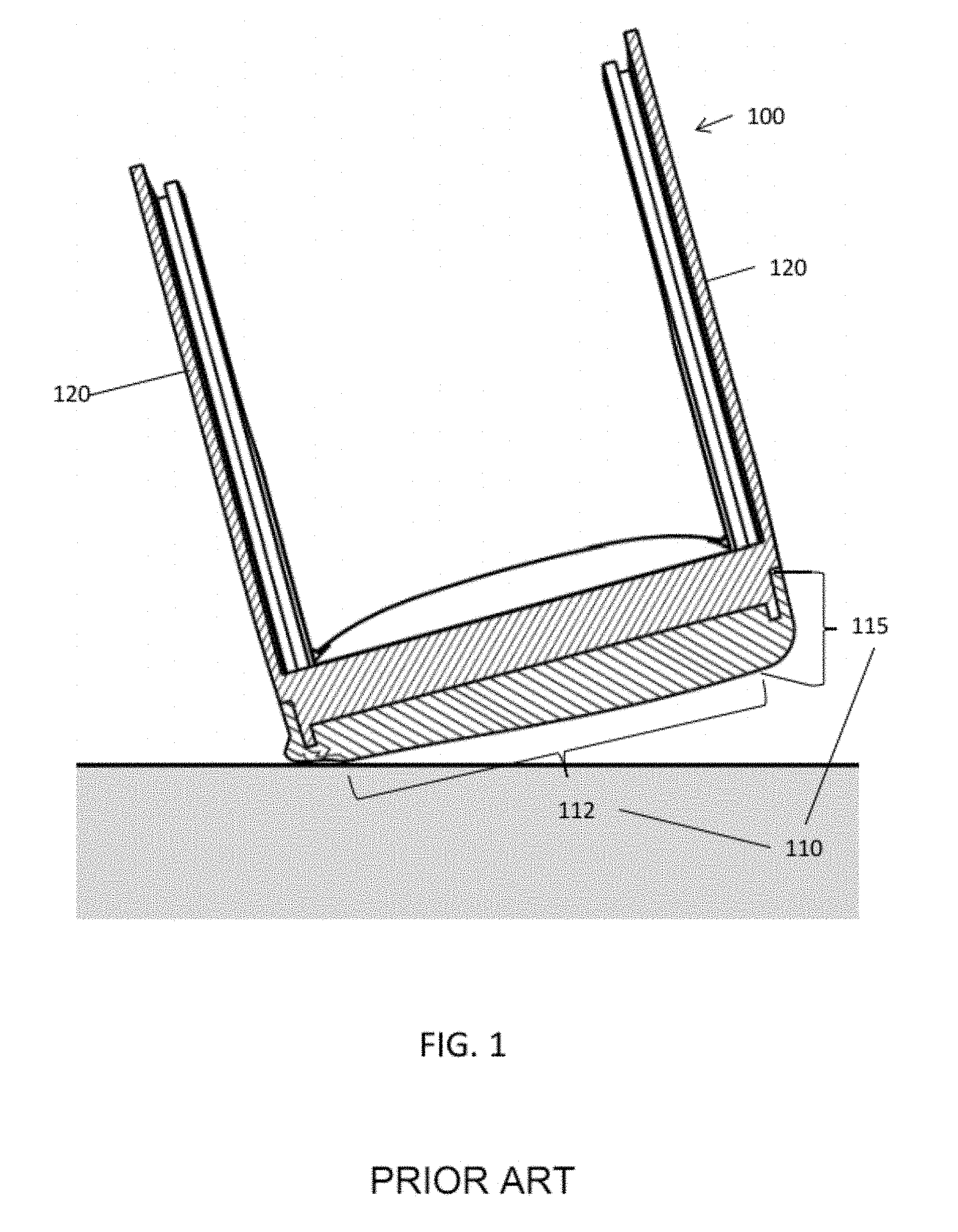
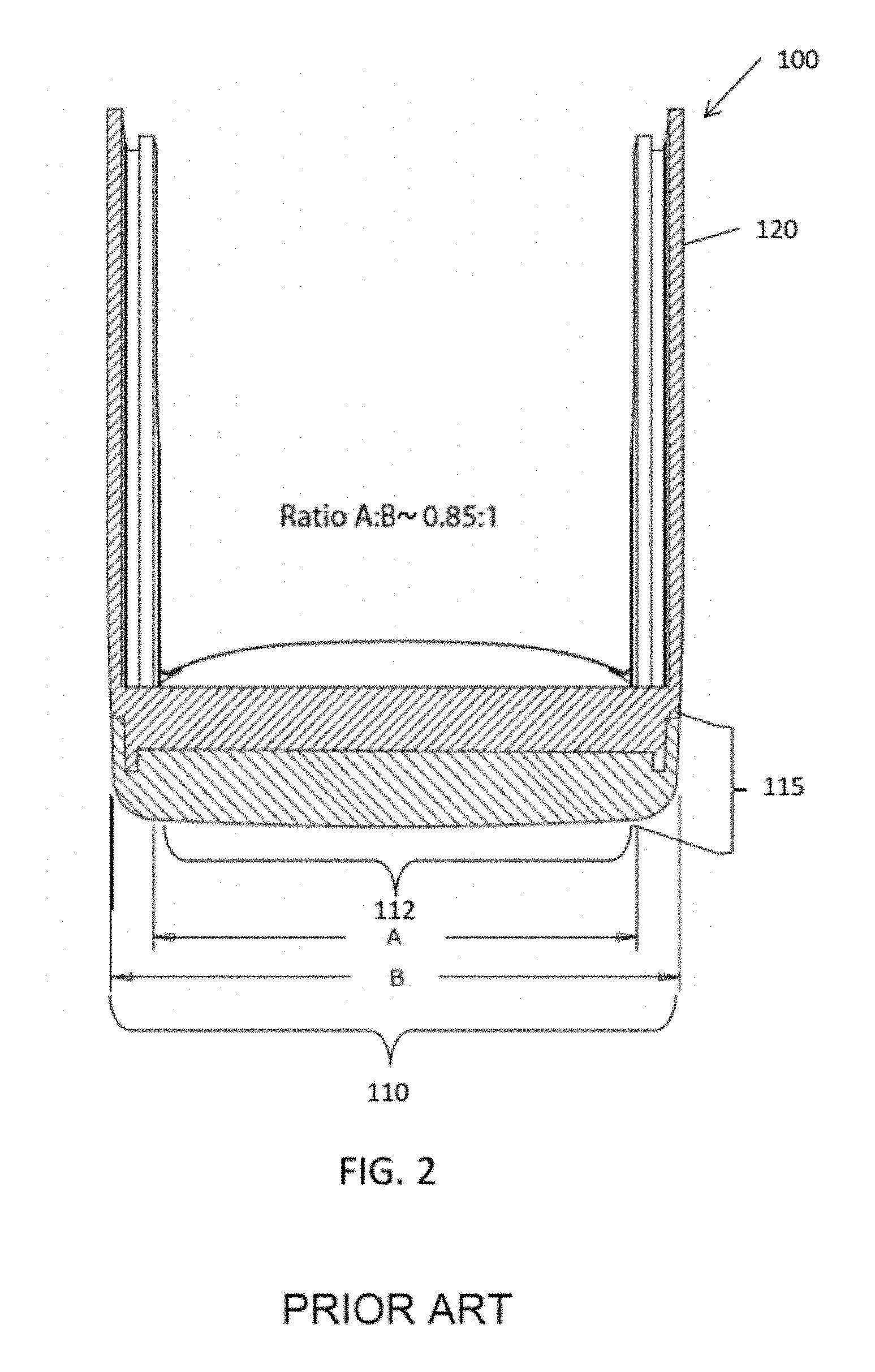
As shown in FIGS. 1 and 2, a depiction of a prior art orthopedic walking boot 100 having a sole 110 with an edge 115 is shown tilted at an angle, such as may occur when a user wishes to pivot to turn, rather than walk in a straight line. The curvature of the sole 110 at either side includes an arcuate edge 115; however, the radius of curvature of the arcuate edge 115 may conventionally be so small that the contact surface of the sole with the ground at the arcuate edge 115 is too small to afford the user stability in the effort to turn or may even hinder the turn due to effectively balancing on an edge, e.g., like a skate blade. As shown in FIG. 2, a typical ratio of the dimension of a substantially flat portion 112 of the sole 110 having a lateral dimension A to a total lateral dimension B, including the two arcuate edges 115, may conventionally be on the order of 0.85 or greater, meaning that the sole is mostly or substantially flat over 85% of the surface of the sole that may make contact with a walking surface. A limited portion at the arcuate edges 115 having curvature upward toward an upper portion 120 of the boot 100 at the sides makes actual contact with the ground. In this configuration, the shape of the sole tends to resist the effort to pivot into the turn, adding stress and discomfort to the user's leg, which may adversely affect recuperation.
Conventional walker boots typically include a break in the curvature from the bottom surface laterally to the vertical sidewall, and lacks a continuously curved (i.e., rolled) edge. In addition, the sole has no provisions for traction on the sidewalls.
There is a need, therefore, to shape the sole of the orthopedic walker boot to improve the user experience, comfort and mobility.
SUMMARY
In an aspect of the disclosure, an orthopedic walking boot for a user includes an outer sole having a substantially continuously curved lateral profile bottom walking surface, wherein a radius of curvature of the lateral walking surface varies between 10 mm and infinity, and an upper portion arranged with the outer sole to support a leg of the user.
In another aspect of the disclosure, an orthopedic walking boot for a user includes an outer sole having a substantially continuously curved lateral profile bottom walking surface, a traction tread on substantially all of the curved bottom of the outer sole, and an upper portion arranged with the outer sole to support a leg of the user, wherein the sole profile curves substantially continuously to merge with the upper portion.
In a further aspect of the disclosure, an orthopedic walking boot for a user includes an outer sole having a bottom surface with a substantially continuously curved lateral profile and front-to-back rolling curvature, and an upper portion arranged with the outer sole to support a leg of the user.
In a still further aspect of the disclosure, an orthopedic walking boot for a user includes an outer sole comprising a primary material and one or more secondary materials, wherein the secondary materials have a greater shock absorbing characteristic than the primary material.
BRIEF DESCRIPTION OF THE DRAWINGS
FIG. 1 is a cross-section view of a prior art orthopedic walking boot in contact with a surface.
FIG. 2 is a cross-section view of the boot of FIG. 1.
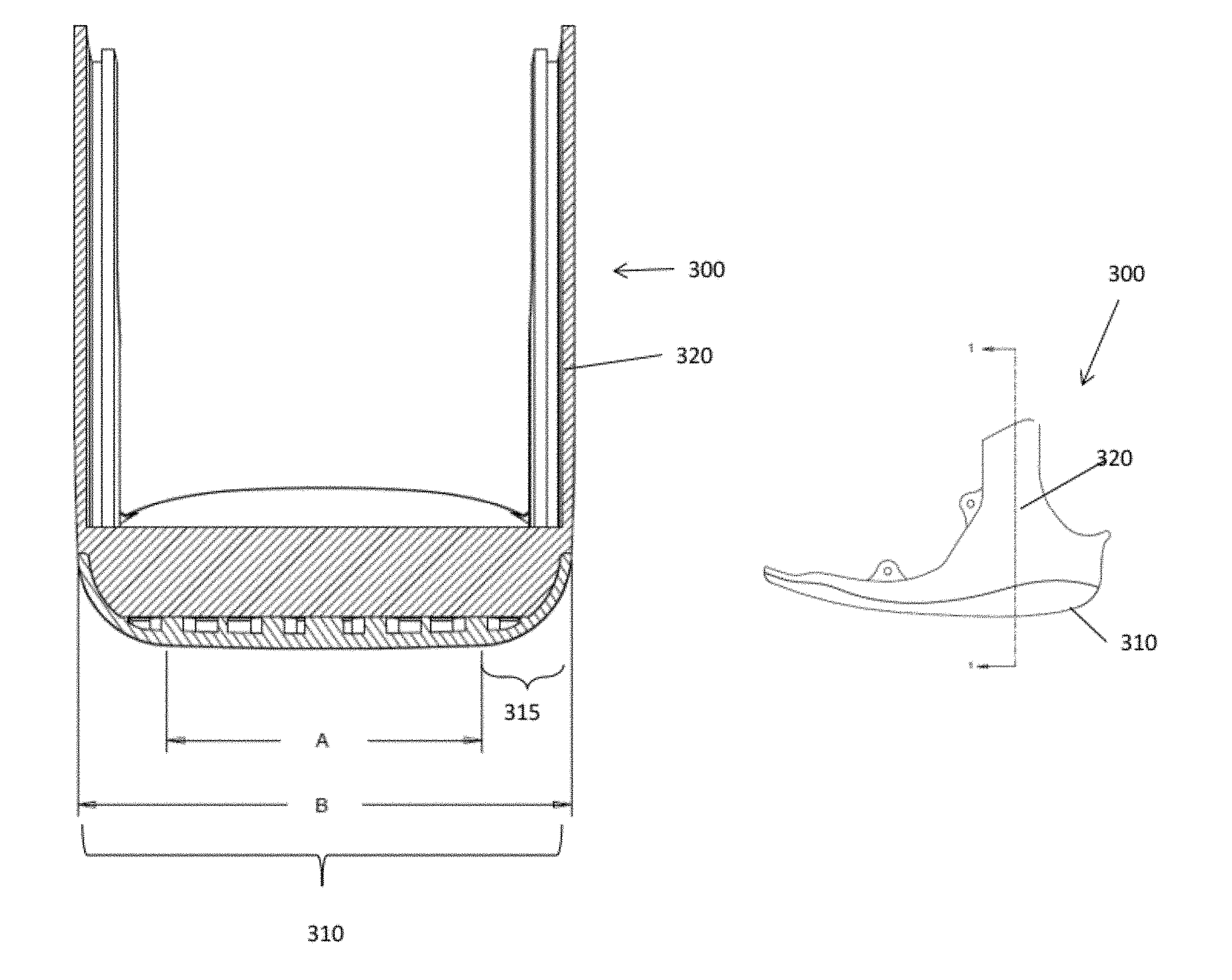
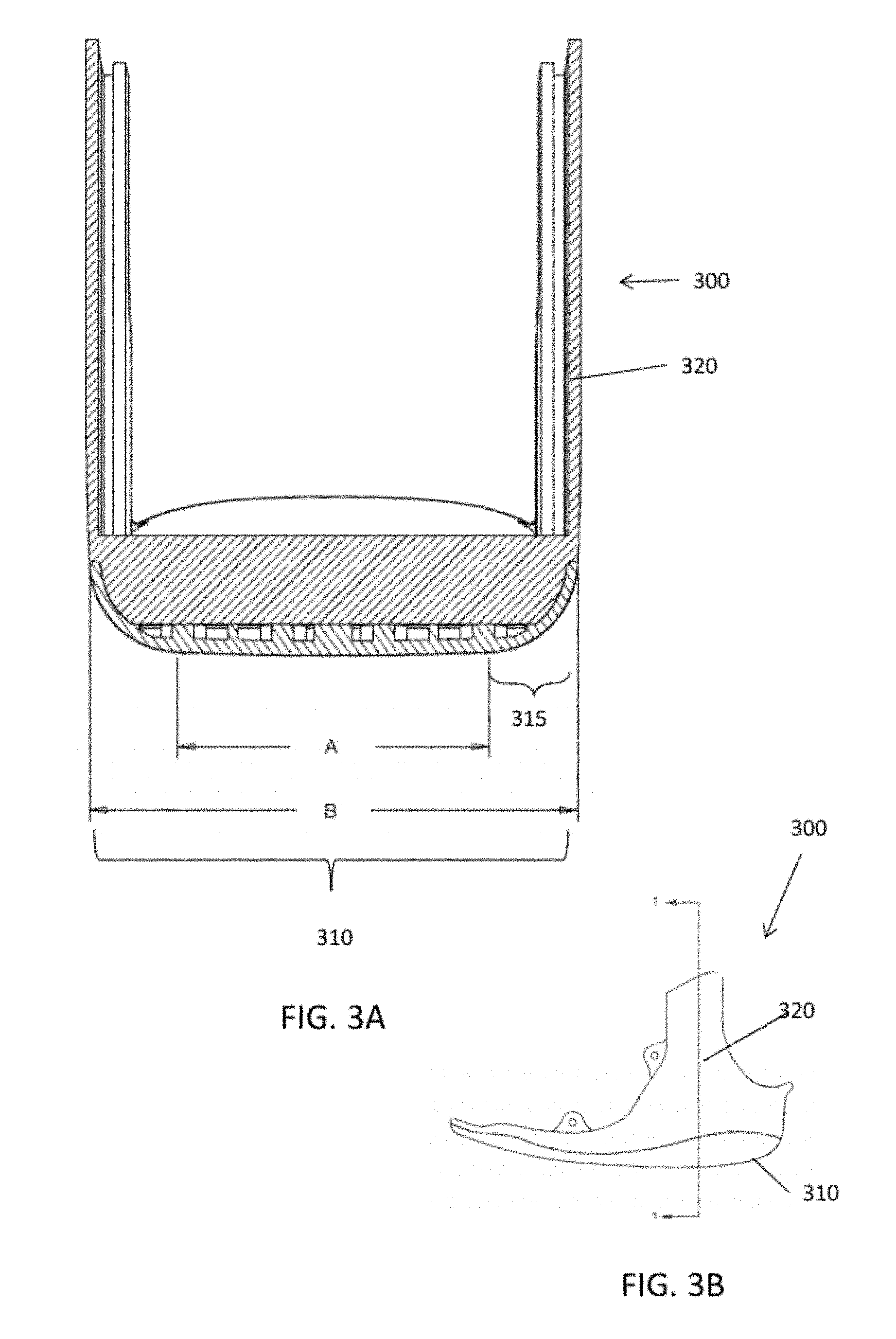
FIG. 3A is a cross-section of an orthopedic walking boot in an aspect of the disclosure.
FIG. 3B is a side view of a portion of the orthopedic walking boot of FIG. 3A.
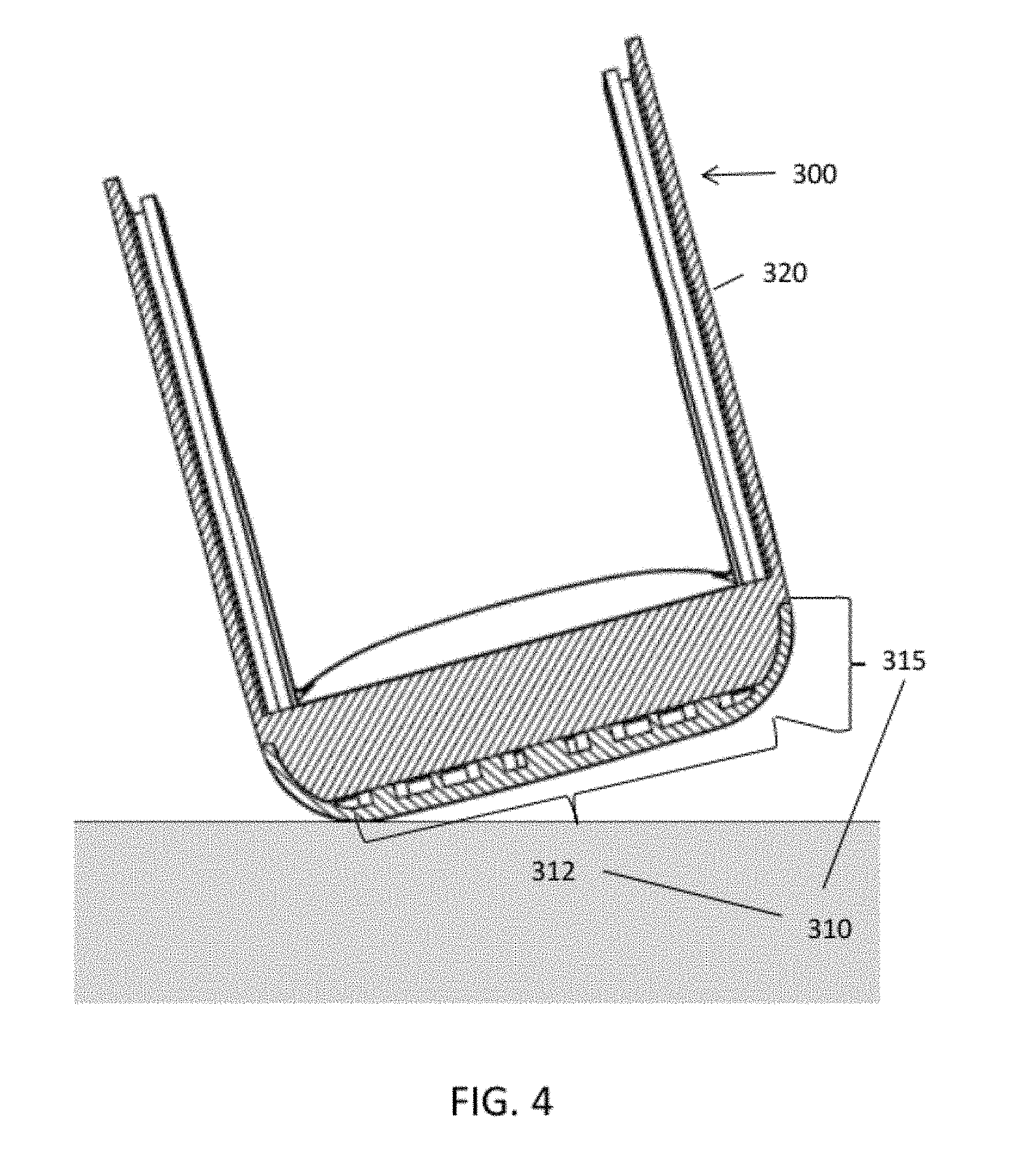
FIG. 4 is a cross-section of the boot of FIG. 3A in partial contact with a surface.
DETAILED DESCRIPTION
Various aspects of the present invention will be described herein with reference to drawings that are schematic illustrations of idealized configurations of the present invention. As such, variations from the shapes of the illustrations as a result, for example, manufacturing techniques and/or tolerances, are to be expected. Thus, the various aspects of the present invention presented throughout this disclosure should not be construed as limited to the particular shapes of elements (e.g., regions, layers, sections, substrates, etc.) illustrated and described herein but are to include deviations in shapes that result, for example, from manufacturing. Thus, the elements illustrated in the drawings are schematic in nature and their shapes are not intended to illustrate the precise shape of an element and are not intended to limit the scope of the present invention, unless intentionally described as such.
It will be understood that when an element such as a region, layer, section, substrate, or the like, is referred to as being "on" another element, it can be directly on the other element or intervening elements may also be present. In contrast, when an element is referred to as being "directly on" another element, there are no intervening elements present. It will be further understood that when an element such as a structure is referred to as being coupled to another element, it can be directly connected to the other element or intervening elements may also be present. Similarly, two elements may be mechanically coupled by being either directly physically connected, or intervening connecting elements may be present. It will be further understood that when an element is referred to as being "formed" on another element, it can be deposited, attached, connected, coupled, or otherwise prepared or fabricated on the other element or an intervening element.
Furthermore, relative terms, such as "lower" or "bottom" and "upper" or "top," may be used herein to describe one element's relationship to another element as illustrated in the drawings. It will be understood that relative terms are intended to encompass different orientations of an apparatus in addition to the orientation depicted in the drawings. By way of example, if a walker in the drawings is turned over, elements described as being on the "lower" side of other elements would then be oriented on the "upper" side of the other elements. The term "lower", can therefore, encompass both an orientation of "lower" and "upper," depending of the particular orientation of the walker. Similarly, if a walker in the drawing is turned over, elements described as "below" or "beneath" other elements would then be oriented "above" the other elements. The terms "below" or "beneath" can, therefore, encompass both an orientation of above and below.
Unless otherwise defined, all terms (including technical and scientific terms) used herein have the same meaning as commonly understood by one of ordinary skill in the art to which this invention belongs. It will be further understood that terms, such as those defined in commonly used dictionaries, should be interpreted as having a meaning that is consistent with their meaning in the context of the relevant art and this disclosure.
It will be further understood that the terms "comprises" and/or "comprising," when used in this specification, specify the presence of stated features, integers, steps, operations, elements, and/or components, but do not preclude the presence or addition of one or more other features, integers, steps, operations, elements, components, and/or groups thereof. The term "and/or" includes any and all combinations of one or more of the associated listed items.
The detailed description set forth below in connection with the appended drawings is intended as a description of various aspects of the present invention and is not intended to represent all aspects in which the present invention may be practiced. The detailed description includes specific details for the purpose of providing a thorough understanding of the present invention. However, it will be apparent to those skilled in the art that the present invention may be practiced without these specific details. In some instances, well-known structures and components are shown in block diagram form in order to avoid obscuring the concepts of the present invention.
Various aspects of the present invention may provide an improved short leg walker that may be fitted easily around the leg to provide support and allow ambulation for the affected limb.
FIG. 3A is a cross-section of an orthopedic walking boot 300 for a lower portion of a user's leg, i.e., from the knee down. As shown in FIG. 3A, a full length outer sole 310 may be rounded at the sides with an arcuate edge 315 where it comes in contact with the walking surface so that the surface of the boot in contact with the ground may transition more smoothly at the edges than may be encountered in a conventional orthopedic walking boot 100. The rounded or arcuate edge 315 disclosed herein allows for the patient to lean more from side to side in the walker to maneuver more easily. With this feature, pivotal rotation of the booted foot is made easier to execute when the user wishes to turn. All portions of the outer sole 310, including the arcuate edge 315, may be fully capable of bearing the weight of the user. Traditionally, outer soles are either a die cut piece of rubber, polyurethane, thermoplastic or like material that is attached permanently to a frame of the walker. These outer soles are usually sloped in the front-to-back direction, as shown in FIG. 3B, for a front-to-back, or longitudinal, rocking action. These outer soles are usually rounded in the front-to-back direction, but not arcuate or rounded in the lateral aspect of the outer sole 310, as shown in FIG. 3A. Because the conventional boot 100 of FIGS. 1 and 2 may usually have a hard angled edge on the lateral sides of the outer sole, the patient, in an effort to assume a natural gait, will actually ride along a portion of the edge, like an ice skate blade, during part of the gait cycle. The problem arises when the patient is on uneven ground, wet surfaces or otherwise unstable surfaces. Because the patient is actually balancing on an edge, it may be more likely that edge becomes cause for the walker to slip, providing a dangerous situation for an already compromised, injured, sometimes weakened, or aged patient.
Because the foot and ankle are set at a specified angle, which may be variable, but typically may be a fixed 90 degree angle, the injured patient may normally adjust his/her gait to not only the frozen angle of the ankle, but to accommodate simultaneously for an angular relationship of the hip to the knee. This causes gross adjustments to the gait/walking patterns, including when the patient pivots to execute a turn. The curved or rounded edge--the arcuate edge 315--will allow for the patient to intuitively adapt to a more normal 3-dimensional gait pattern by being able to roll or use the edge 315 of the walker by leaning the body more side-to-side, as in a healthy walking gait, thus accommodating for the injury as well as the ankle being frozen in a 90 degree angle.
The patient may be more comfortable from the first strides when attempting ambulation in the walker 300. The walker may be beneficially used in a very wide range of injuries and a very wide spectral profile of patient disabilities, e.g., age, physical fitness and/or disabilities, and injury types. For example, a teenage athlete with a broken leg has a very different gate requirement and pain tolerance than an elderly, overweight, health compromised senior citizen who may also suffer other multiple chronic conditions (e.g., arthritis, hip and knee joint degradation, etc.) that can have an additional dramatic effect on gait requirements.
As the injuries progress in healing, the gait pattern may become more aggressive as the pain is eliminated when using the walker 300. Because the patient may be more comfortable at all stages of recuperation, he/she may want to adapt a more natural gait, e.g., walking, twisting, turning quickly, etc. Conscious thought is rarely given to the process of walking in our normal lives. However, people will constantly pivot around a chair, twist when exiting a car, and pivot during normal walking activity when maneuvering around or away from objects and corners, i.e., negotiating normal environments such as the household or work, changing walking surfaces, such as from carpet to hard surfaces, etc. A conventional walker with a sharp cornered arcuate side edge tends to force a wearer to walk in a straight line along that edge. A walker with a more rounded curved side edge allows for less restricted freedom to maneuver more easily. An outer sole with a relatively sharp cornered edge may result in the patient teetering and occasionally slipping or sliding on the edge. The curved surface disclosed herein allows for an easier pivot, roll, turn twist, etc., and improved contact traction on substantially any condition of the walking surface, e.g., snow, ice, rain, oily/slippery surfaces, gravel, rocks, stairs, curbs, all the surfaces we may consistently maneuver on in normal ambulatory activity, to which barely any thought is normally given.
Referring to FIG. 4, the arcuate nature of the walker outer sole 310 may have a lateral profile that is continuous across the width of the entire outer sole 310 and terminate without a substantial step-off between the lateral portion 312 and the arcuate edge 315, thereby being congruent with substantially continuous curvature over the entirety of the outer sole lateral surface profile from the heel striking area to the toe. That is, a lateral portion 312 of lateral dimension A of the sole 315 may have a radius of curvature in the lateral plane that is large enough so as to appear that the lateral portion 312 is approximately or substantially flat. The arcuate edges 315 may have a radius of curvature in a smaller range which is, however still larger than for the arcuate edges 115 of the conventional walker sole 110.
A total dimension B, includes the lateral portion 312 plus the two arcuate edges 315. At the interface between the approximately or substantially flat lateral portion and each of the two arcuate edges 315 the radius of curvature changes to a smaller value, however the surface of the sole has a transition from one portion to the other, with no substantial discontinuous break in contour between the two parts (i.e., between the substantially flat or slightly curved lateral portion of dimension A and the arcuate edge 315) corresponding to a change in slope of the contour break of no more than 20 degrees. Thus, the step-off between the lateral portion 312 and the arcuate edge 315 is restricted to be equal or less than 20 degrees. For example, the radius of curvature may transition between approximately 10 mm in the region of the arcuate edge 315 to a larger value--up to infinity--in the lateral portion 312 of the outer sole 310 indicated by the dimensions A, provided there is no substantial cusp or discontinuity greater than 20 degrees of the surface smoothness from one portion to the other. More preferably, the radius of curvature in the region of the arcuate edge 315 may be approximately 30 cm. This may vary, for example, according to boot size.
A value of the radius of curvature of infinity in the lateral portion 312 indicates a flat portion of the outer sole 310. The radius of curvature in the lateral portion 312 may be in a first range of values from a minimum specified value up to infinity. The radius of curvature in the arcuate edge 315 may be in a second range of values from, for example, the minimum value specified for the lateral portion 312 down to a smaller specified value. The substantially continuous curvature over the entirety of the outer sole lateral surface profile determines that the lateral contour of the outer sole 310 changes smoothly from lateral portion 312 to arcuate edge 315, i.e., with no sharp edges greater than, for example, a 20 degree step-off
It may be understood that a tread pattern in the surface of the outer sole 310 may be considered as a perturbation of the surface of the outer sole 310, and is not considered in the definition of the radius of curvature.
In a conventional walker, the ratio A:B may be on the order of 1.gtoreq.A:B.gtoreq.0.85. Commonly, the ratio may be A:B.about.0.85. In the walker boot 300 the ratio A:B may be lower, e.g., on the order of 0.85>A:B.gtoreq.0. More preferably the ratio A:B may be A:B.about.0.63.
Another feature is a scalloping or curved recessing on the inside of the walker in the upper portion 320. Traditionally the insides of the walker upper portion 120 are "flat," i.e., lack a contoured surface to accommodate the ankle. The inside of the upper portion 120 of a conventional walker 100 may be interfitted into the flat inside walls in order to provide a secure fitting. Various embodiments of the walker 300 disclosed herein may have a curved or recessed inner surface (not shown) of the upper portion 320 which accommodates the natural curvature of the ankle and foot. This provides a pre-relieved area or recess to accommodate the boney prominences of the foot and ankle and also accommodates swelling patterns that are predictably present with injuries to the area.
In yet another embodiment of the disclosure, the upper portion 320, may be flared outwardly (not shown) to conform to a shape of the wearer's calf, which has an increasing cross-section of the leg with distance from the ankle.
In still another aspect of the disclosure, the outer sole may include a plurality of materials such as, for example, a primary material for structural strength, and one or more secondary materials configured to provide a greater degree of shock absorption to reduce impact stress on the user's foot, particularly from the heal to the mid-foot. The primary and secondary materials may be structurally distinct and separate over the extent of the outer sole to provide different impact characteristics according to location, or alternatively a mixture in various proportions of the primary and secondary materials may provide differing degrees of shock absorption at different locations of the sole of the foot. The mixture may be achieved by controlled additive mixing of secondary materials.
In still another aspect of the disclosure, shock attenuation to the user's foot may be achieved by including the primary and secondary materials as described above in an insole of the walker.
It may be readily appreciated that the walker boot as described above may simultaneously solve a number of deficiencies found in the prior art. These deficiencies in the prior art may include, but are not limited to, an inability to accommodate: a user's supination or pronation tendencies, changes in mobility during recovery, the need for postural accommodations including the hip, knee, back and shoulders, and desired freedom of movement on various terrains, such as, but not limited to, stairs and inclines.
The claims are not intended to be limited to the various aspects of this disclosure, but are to be accorded the full scope consistent with the language of the claims. It is noted that specific illustrative embodiments of the invention have been shown in the drawings and described in detail hereinabove. It is to be understood that various changes and modifications may be made without departing from the spirit and scope of the invention. All structural and functional equivalents to the elements of the various aspects described throughout this disclosure that are known or later come to be known to those of ordinary skill in the art are expressly incorporated herein by reference and are intended to be encompassed by the claims. Moreover, nothing disclosed herein is intended to be dedicated to the public regardless of whether such disclosure is explicitly recited in the claims. No claim element is to be construed under the provisions of 35 U.S.C. .sctn. 112, sixth paragraph, unless the element is expressly recited using the phrase "means for" or, in the case of a method claim, the element is recited using the phrase "step for."
* * * * *
References
D00000
D00001
D00002
D00003
D00004
XML
uspto.report is an independent third-party trademark research tool that is not affiliated, endorsed, or sponsored by the United States Patent and Trademark Office (USPTO) or any other governmental organization. The information provided by uspto.report is based on publicly available data at the time of writing and is intended for informational purposes only.
While we strive to provide accurate and up-to-date information, we do not guarantee the accuracy, completeness, reliability, or suitability of the information displayed on this site. The use of this site is at your own risk. Any reliance you place on such information is therefore strictly at your own risk.
All official trademark data, including owner information, should be verified by visiting the official USPTO website at www.uspto.gov. This site is not intended to replace professional legal advice and should not be used as a substitute for consulting with a legal professional who is knowledgeable about trademark law.