Priority of beam failure recovery request and uplink channels
Zhou , et al. December 1, 2
U.S. patent number 10,855,359 [Application Number 16/101,189] was granted by the patent office on 2020-12-01 for priority of beam failure recovery request and uplink channels. This patent grant is currently assigned to Comcast Cable Communications, LLC. The grantee listed for this patent is Comcast Cable Communications, LLC. Invention is credited to Alireza Babaei, Esmael Hejazi Dinan, Hyoungsuk Jeon, Kyungmin Park, Hua Zhou.


View All Diagrams
| United States Patent | 10,855,359 |
| Zhou , et al. | December 1, 2020 |
Priority of beam failure recovery request and uplink channels
Abstract
Systems, apparatuses, and methods are described for wireless communications. A wireless device may distribute power for various transmission types based on a priority, which may be received from a base station.
| Inventors: | Zhou; Hua (Herndon, VA), Dinan; Esmael Hejazi (Herndon, VA), Jeon; Hyoungsuk (Fairfax, VA), Park; Kyungmin (Oakton, VA), Babaei; Alireza (Arlington, VA) | ||||||||||
|---|---|---|---|---|---|---|---|---|---|---|---|
| Applicant: |
|
||||||||||
| Assignee: | Comcast Cable Communications,
LLC (Philadelphia, PA) |
||||||||||
| Family ID: | 1000005217567 | ||||||||||
| Appl. No.: | 16/101,189 | ||||||||||
| Filed: | August 10, 2018 |
Prior Publication Data
| Document Identifier | Publication Date | |
|---|---|---|
| US 20190052339 A1 | Feb 14, 2019 | |
Related U.S. Patent Documents
| Application Number | Filing Date | Patent Number | Issue Date | ||
|---|---|---|---|---|---|
| 62543826 | Aug 10, 2017 | ||||
| Current U.S. Class: | 1/1 |
| Current CPC Class: | H04W 52/346 (20130101); H04W 52/40 (20130101); H04B 7/0695 (20130101); H04W 76/19 (20180201); H04B 17/309 (20150115); H04B 17/17 (20150115); H04W 52/50 (20130101); H04W 52/30 (20130101); H04W 52/367 (20130101); H04B 7/0632 (20130101); H04W 52/281 (20130101); H04L 27/2692 (20130101); H04W 36/305 (20180801); H04L 27/2613 (20130101); H04W 74/0833 (20130101); H04B 7/0628 (20130101) |
| Current International Class: | H04B 7/06 (20060101); H04W 52/28 (20090101); H04L 27/26 (20060101); H04W 74/08 (20090101); H04W 76/19 (20180101); H04W 36/30 (20090101); H04B 17/309 (20150101); H04W 52/34 (20090101); H04W 52/36 (20090101); H04W 52/50 (20090101); H04B 17/17 (20150101); H04W 52/40 (20090101); H04W 52/30 (20090101) |
References Cited [Referenced By]
U.S. Patent Documents
| 9125218 | September 2015 | Chang |
| 9585188 | February 2017 | Jang et al. |
| 9736795 | August 2017 | Dinan |
| 9949298 | April 2018 | Akoum et al. |
| 10278160 | April 2019 | Kgiwal et al. |
| 10333672 | June 2019 | Nagaraja et al. |
| 10461994 | October 2019 | Liu et al. |
| 10541741 | January 2020 | Islam et al. |
| 10555359 | February 2020 | Xia et al. |
| 2010/0279700 | November 2010 | Kim |
| 2013/0039345 | February 2013 | Kim et al. |
| 2013/0188580 | July 2013 | Dinan |
| 2013/0250828 | September 2013 | Chou et al. |
| 2015/0189574 | July 2015 | Ng et al. |
| 2015/0208462 | July 2015 | Lee et al. |
| 2015/0271796 | September 2015 | Jang et al. |
| 2015/0365921 | December 2015 | Wu |
| 2017/0195998 | July 2017 | Zhang et al. |
| 2017/0207843 | July 2017 | Jung et al. |
| 2017/0332406 | November 2017 | Islam et al. |
| 2017/0339662 | November 2017 | Lin et al. |
| 2017/0346545 | November 2017 | Islam et al. |
| 2017/0373731 | December 2017 | Guo et al. |
| 2018/0006770 | January 2018 | Guo et al. |
| 2018/0034611 | February 2018 | Nagaraja et al. |
| 2018/0054348 | February 2018 | Luo et al. |
| 2018/0054382 | February 2018 | Luo et al. |
| 2018/0054783 | February 2018 | Luo et al. |
| 2018/0054811 | February 2018 | Luo et al. |
| 2018/0054812 | February 2018 | Luo et al. |
| 2018/0054832 | February 2018 | Luo et al. |
| 2018/0083753 | March 2018 | Nagaraja et al. |
| 2018/0098334 | April 2018 | Tie et al. |
| 2018/0110066 | April 2018 | Luo et al. |
| 2018/0115940 | April 2018 | Abedini et al. |
| 2018/0115990 | April 2018 | Abedini et al. |
| 2018/0124687 | May 2018 | Park et al. |
| 2018/0132266 | May 2018 | Chen et al. |
| 2018/0138962 | May 2018 | Islam et al. |
| 2018/0176958 | June 2018 | Islam et al. |
| 2018/0191422 | July 2018 | Xia et al. |
| 2018/0219604 | August 2018 | Lu et al. |
| 2018/0220448 | August 2018 | Akkarakaran et al. |
| 2018/0227899 | August 2018 | Yu et al. |
| 2018/0234960 | August 2018 | Nagaraja et al. |
| 2018/0241452 | August 2018 | Akkarakaran et al. |
| 2018/0249453 | August 2018 | Nagaraja et al. |
| 2018/0270689 | September 2018 | Akkarakaran |
| 2018/0270698 | September 2018 | Babaei et al. |
| 2018/0270699 | September 2018 | Babaei et al. |
| 2018/0270700 | September 2018 | Babaei et al. |
| 2018/0278310 | September 2018 | Lee et al. |
| 2018/0279150 | September 2018 | He et al. |
| 2018/0279193 | September 2018 | Park et al. |
| 2018/0279229 | September 2018 | Dinan et al. |
| 2018/0288756 | October 2018 | Xia et al. |
| 2018/0302889 | October 2018 | Guo et al. |
| 2018/0310321 | October 2018 | Basu Mallick et al. |
| 2018/0317123 | November 2018 | Chen et al. |
| 2018/0323856 | November 2018 | Xiong |
| 2018/0324723 | November 2018 | Akkarakaran et al. |
| 2018/0324867 | November 2018 | Basu Mallick et al. |
| 2018/0343653 | November 2018 | Guo |
| 2018/0351611 | December 2018 | Nagaraja et al. |
| 2018/0359790 | December 2018 | Ingale et al. |
| 2018/0367374 | December 2018 | Liu et al. |
| 2018/0368126 | December 2018 | Islam et al. |
| 2018/0368142 | December 2018 | Liou |
| 2018/0375560 | December 2018 | Wei |
| 2019/0028174 | January 2019 | Chakraborty et al. |
| 2019/0037423 | January 2019 | Yu et al. |
| 2019/0037498 | January 2019 | Tseng |
| 2019/0044792 | February 2019 | Kwon |
| 2019/0053294 | February 2019 | Xia et al. |
| 2019/0059129 | February 2019 | Luo et al. |
| 2019/0074882 | March 2019 | Zhou et al. |
| 2019/0075600 | March 2019 | Kwon et al. |
| 2019/0090143 | March 2019 | Luo et al. |
| 2019/0104549 | April 2019 | Deng et al. |
| 2019/0141555 | May 2019 | Tooher et al. |
| 2019/0159234 | May 2019 | Yi et al. |
| 2019/0173740 | June 2019 | Zhang et al. |
| 2019/0268893 | August 2019 | Tsai et al. |
| 2020/0059285 | February 2020 | Zhang et al. |
| 2020/0059898 | February 2020 | Osawa et al. |
| 2020/0068416 | February 2020 | Kang et al. |
| 2020/0092785 | March 2020 | Yang |
| 2020/0120714 | April 2020 | Wang et al. |
| 2020/0178338 | June 2020 | Ahn et al. |
| 108809580 | Nov 2018 | CN | |||
| 3397015 | Oct 2018 | EP | |||
| 3424152 | Jan 2019 | EP | |||
| 2013025142 | Feb 2013 | WO | |||
| 2017024516 | Feb 2017 | WO | |||
| 2017123060 | Jul 2017 | WO | |||
| 2017135803 | Aug 2017 | WO | |||
| 2017151876 | Sep 2017 | WO | |||
| 2017196612 | Nov 2017 | WO | |||
| 2017217898 | Dec 2017 | WO | |||
| 2018017840 | Jan 2018 | WO | |||
| 2018031327 | Feb 2018 | WO | |||
| 2018031799 | Feb 2018 | WO | |||
| 2018038859 | Mar 2018 | WO | |||
| 2018038860 | Mar 2018 | WO | |||
| 2018038861 | Mar 2018 | WO | |||
| 2018038862 | Mar 2018 | WO | |||
| 2018038864 | Mar 2018 | WO | |||
| 2018075985 | Apr 2018 | WO | |||
| 2018084544 | May 2018 | WO | |||
| 2018128426 | Jul 2018 | WO | |||
| 2018129300 | Jul 2018 | WO | |||
| 2018136300 | Jul 2018 | WO | |||
| 2018141303 | Aug 2018 | WO | |||
| 2018144592 | Aug 2018 | WO | |||
| 2018148552 | Aug 2018 | WO | |||
| 2018156299 | Aug 2018 | WO | |||
| 2018156696 | Aug 2018 | WO | |||
| 2018169848 | Sep 2018 | WO | |||
| 2018170481 | Sep 2018 | WO | |||
| 2018171476 | Sep 2018 | WO | |||
| 2018174667 | Sep 2018 | WO | |||
| 2018174800 | Sep 2018 | WO | |||
| 2018175303 | Sep 2018 | WO | |||
| 2018190617 | Oct 2018 | WO | |||
| 2018195975 | Nov 2018 | WO | |||
| 2018196520 | Nov 2018 | WO | |||
| 2018199074 | Nov 2018 | WO | |||
| 2018199079 | Nov 2018 | WO | |||
| 2018199100 | Nov 2018 | WO | |||
| 2018199162 | Nov 2018 | WO | |||
| 2018199243 | Nov 2018 | WO | |||
| 2018200579 | Nov 2018 | WO | |||
| 2018201450 | Nov 2018 | WO | |||
| 2018201990 | Nov 2018 | WO | |||
| 2018203719 | Nov 2018 | WO | |||
| 2018203785 | Nov 2018 | WO | |||
| 2018204255 | Nov 2018 | WO | |||
| 2018204718 | Nov 2018 | WO | |||
| 2018204922 | Nov 2018 | WO | |||
| 2018222276 | Dec 2018 | WO | |||
| 2018227464 | Dec 2018 | WO | |||
| 2018227551 | Dec 2018 | WO | |||
| 2018228187 | Dec 2018 | WO | |||
| 2018230862 | Dec 2018 | WO | |||
| 2018231655 | Dec 2018 | WO | |||
| 2018232090 | Dec 2018 | WO | |||
| 2018232259 | Dec 2018 | WO | |||
| 2018237400 | Dec 2018 | WO | |||
| 2019004694 | Jan 2019 | WO | |||
| 2019032882 | Feb 2019 | WO | |||
Other References
|
R1-1704478 3GPP TSG RAN WG1 Meeting #88bis, Spokane, USA, Apr. 3-7, 2017, Source: Fujitsu, Title: Discussion on beam failure recovery procedure. cited by applicant . R1-1704723 3GPP TSG RAN WG1 Meeting #88bis, Spokane, USA, Apr. 3-7, 2017, Source: Intel Corporation, Title: Details for UL Beam Management. cited by applicant . R1-1704725 3GPP TSG RAN WG1 Meeting #88bis, Spokane, USA, Apr. 3-7, 2017, Source: Intel Corporation, Title: On UE Initiated Beam Recovery. cited by applicant . R1-1705582 3GPP TSG RAN WG1 Meeting #88bis, Spokane, USA, Apr. 3-7, 2017, Source: Qualcomm Incorporated, Title: Beam recovery procedures. cited by applicant . R1-1705893 3GPP TSG RAN WG1 Meeting #88bis, Spokane, USA, Apr. 3-7, 2017, Source: Ericsson, Title: Beam fallure detection and beam recovery actions. cited by applicant . R1-1705961 3GPP TSG RAN WG1 Meeting #88bis, Spokane, USA, Apr. 3-7, 2017, Source: Nokia, Alcatel-Lucent Shanghai Bell, Title: Beam Recovery in NR. cited by applicant . R1-1706928 3GPP TSG RAN WG1 Meeting #89, Hangzhou, China, May 15-19, 2017, Source: Huawei, HiSilicon, Title: Beam management across multiple carriers. cited by applicant . R1-1707255 3GPP TSG RAN WG1 Meeting #89, Hangzhou, China, May 15-19, 2017, Source: Fujitsu, Title: Discussion on beam failure recovery procedure. cited by applicant . R1-1707356 3GPP TSG RAN WG1 Meeting #89, Hangzhou, China, May 15-19, 2017, Source: Intel Corporation, Title: Discussion for Mechanism to Recover from Beam Failure. cited by applicant . R1-1707477 3GPP TSG RAN WG1 Meeting #89, Hangzhou, China, May 15-19, 2017, Source: CATT, Title: Discussion on DL beam recovery. cited by applicant . R1-1707698 3GPP TSG RAN WG1 Meeting #89, Hangzhou, China, May 15-19, 2017, Source: Guangdong OPPO Mobile Telecom, Title: On Beam Recovery Mechanism. cited by applicant . R1-1707782 3GPP TSG RAN WG1 Meeting #89, Hangzhou, China, May 15-19, 2017, Source: Spreadtrum Communications, Title: Discussion on UE initiated recovery from beam failure. cited by applicant . R1-1707814 3GPP TSG RAN WG1 Meeting #89, Hangzhou, China, May 15-19, 2017, Source: NEC, Title: Low latency beam failure recovery by PRACH/PRACH-like. cited by applicant . R1-1707954 3GPP TSG RAN WG1 Meeting #89, Hangzhou, China, May 15-19, 2017, Source: Samsung, Title: Discussion on beam recovery procedure. cited by applicant . R1-1708678 3GPP TSG RAN WG1 Meeting #89, Hangzhou, China, May 15-19, 2017, Source: Ericsson, Title: Beam failure recovery mechanism. cited by applicant . R1-1708905 3GPP TSG RAN WG1 Meeting #89, Hangzhou, China, May 15-19, 2017, Source: Nokia, Alcatel-Lucent Shanghai Bell, Title: Beam Recovery. cited by applicant . R1-1710144 3GPP TSG RAN WG1 NR Ad-Hoc #2, Qingdao, China, Jun. 27-30, 2017, Source: Guangdong OPPO Mobile Telecom, Title: On Beam Recovery Mechanism. cited by applicant . R1-1710185 3GPP TSG RAN WG1 NR Ad-Hoc #2, Qingdao, China, Jun. 27-30, 2017, Source: ZTE, Title: Discussion on beam recovery mechanism. cited by applicant . R1-1710527 3GPP TSG RAN WG1 NR Ad-Hoc #2, Qingdao, China, Jun. 27-30, 2017, Source: Intel Corporation, Title: Discussion for mechanism to recover from beam failure. cited by applicant . R1-1710655 3GPP TSG RAN WG1 NR Ad-Hoc #2, Qingdao, China, Jun. 27-30, 2017, Source: Samsung, Title: Beam failure recovery. cited by applicant . R1-1714251 3GPP TSG RAN WG1 Meeting #90, Prague, Czech Republic, Aug. 21-25, 2017, Source: Nokia, Nokia Shanghai Bell, Title: Beam recovery in NR. cited by applicant . R1-1715468 3GPP TSG RAN WG1 Meeting NR#3, Nagoya, Japan, Sep. 18-21, 2017, Source: Huawei, HiSilicon, Title: Beam Failure Recovery Design Details. cited by applicant . R1-1715860 3GPP TSG RAN WG1 Meeting NR#3, Nagoya, Japan, Sep. 18-21, 2017, Source: LG Electronics, Title: Discussion on beam failure recovery. cited by applicant . R1-1800362 3GPP TSG RAN WG1 Meeting AH 1801, Vancouver, Canada, Jan. 22-26, 2018, Source: LG Electronics, Title: Clarification on PDCCH beam indication by higher-layers. cited by applicant . R1-1800363 3GPP TSG RAN WG1 Meeting AH 1801, Vancouver, Canada, Jan. 22-26, 2018, Source: LG Electronics, Title: Text proposals on UL beam management. cited by applicant . R1-1800364 3GPP TSG RAN WG1 Meeting AH 1801, Vancouver, Canada, Jan. 22-26, 2018, Source: LG Electronics, Title: Discussion on PHY and MAC operation for beam failure recovery. cited by applicant . R1-1800401 3GPP TSG RAN WG1 Meeting AH 1801, Vancouver, Canada, Jan. 22-26, 2018, Source: Lenovo, Motorola Mobility, Title: Corrections on beam management. cited by applicant . R1-1800402 3GPP TSG RAN WG1 Meeting AH 1801, Vancouver, Canada, Jan. 22-26, 2018, Source: Lenovo, Motorola Mobility, Title: Corrections on beam failure recovery. cited by applicant . R1-1800432 3GPP TSG RAN WG1 Meeting AH 1801, Vancouver, Canada, Jan. 22-26, 2018, Source: Samsung, Title: Issues on beam management. cited by applicant . R1-1800433 3GPP TSG RAN WG1 Meeting AH 1801, Vancouver, Canada, Jan. 22-26, 2018, Source: Samsung, Title: Aperiodic beam reporting. cited by applicant . R1-1800434 3GPP TSG RAN WG1 Meeting AH 1801, Vancouver, Canada, Jan. 22-26, 2018, Source: Samsung, Title: Issues on beam failure recovery. cited by applicant . R1-1800472 3GPP TSG RAN WG1 Meeting AH 1801, Vancouver, Canada, Jan. 22-26, 2018, Source: Samsung, Title: PHR for CA. cited by applicant . R1-1800498 3GPP TSG RAN WG1 Meeting AH 1801, Vancouver, Canada, Jan. 22-26, 2018, Source: OPPO, Title: Text Proposal for Beam Management. cited by applicant . R1-1800499 3GPP TSG RAN WG1 Meeting AH 1801, Vancouver, Canada, Jan. 22-26, 2018, Source: OPPO, Title: Text Proposal for Beam Failure Recovery. cited by applicant . R1-1715941 3GPP TSG RAN WG1 Meeting NR#3, Nagoya Japan, Sep. 18-21, 2017, Source: Samsung, Title: Beam Failure recovery. cited by applicant . R1-1716295 3GPP TSG RAN WG1 Meeting NR#3, Nagoya, Japan, Sep. 18-21, 2017, Source: Intel Corporation, Title: Remaining Issues on Beam Failure Recovery. cited by applicant . R1-1716397 3GPP TSG RAN WG1 Meeting NR#3, Nagoya, Japan, Sep. 18-21, 2017, Source: Qualcomm Incorporated, Title: Beam recovery procedure. cited by applicant . R1-1716500 3GPP TSG RAN WG1 Meeting NR#3, Nagoya, Japan, Sep. 18-21, 2017, Source: Nokia, Nokia Shanghai Bell, Title Beam Recovery in NR. cited by applicant . R1-1716469 3GPP TSG RAN WG1 Meeting NR#3, Nagoya, Japan, Sep. 18-21, 2017: Source: InterDigital, Inc., Title: Remaining issues on beam recovery. cited by applicant . R1-1717302 3GPP TSG RAN WG1 Meeting #90bis, Prague, Czech Republic, Oct. 9-13, 2017, Source: Huawei, HiSilicon Title: Beam failure recovery design details. cited by applicant . R1-1717369 3GPP TSG RAN WG1 Meeting #90bis, Prague, Czech Republic, Oct. 9-13, 2017, Source: Intel Corporation, Title: Remaining Issues on Beam Failure Recovery. cited by applicant . R1-1717473 3GPP TSG RAN WG1 Meeting #90bis, Prague, Czech Republic, Oct. 9-13, 2017, Source: vivo, Title: Discussion on beam failure recovery. cited by applicant . R1-1717606 3GPP TSG RAN WG1 Meeting #90bis, Prague, Czech Republic, Oct. 9-13, 2017, Source: Samsung, Title: Beam failure recovery. cited by applicant . R1-1717942 3GPP TSG RAN WG1 Meeting #90bis, Prague, Czech Republic, Oct. 9-13, 2017, Source: LG Electronics, Title: Discussion on beam failure recovery. cited by applicant . R1-1718010 3GPP TSG RAN WG1 Meeting #90bis, Prague, Czech Republic, Oct. 9-13, 2017, Source: NEC, Title: Discussion on Beam Failure Recovery. cited by applicant . R1-1718055 3GPP TSG RAN WG1 Meeting #90bis, Prague, Czech Republic, Oct. 9-13, 2017, Source: OPPO, Title: Discussion on Beam Recovery Mechanism. cited by applicant . R1-1718193 3GPP TSG RAN WG1 Meeting #90bis, Prague, Czech Republic, Oct. 9-13, 2017, Source: NTT DOCOMO, Title: Views on beam recovery. cited by applicant . R1-1718389 3GPP TSG RAN WG1 Meeting #90bis, Prague, Czech Republic, Oct. 9-13, 2017, Source: AT&T, Title: Beam Recovery for Full and Partial Control Channel Failure. cited by applicant . R1-1718512 3GPP TSG RAN WG1 Meeting #90bis, Prague, Czech Republic, Oct. 9-13, 2017, Source: Nokia, Nokia Shanghai Bell, Title: Beam Recovery in NR. cited by applicant . R1-1718542 3GPP TSG RAN WG1 Meeting #90bis, Prague Czech Republic, Oct. 9-13, 2017, Source: Qualcomm Incorpated, Title: Beam recovery procedure. cited by applicant . R1-1719423 3GPP TSG RAN WG1 Meeting #91, Reno, USA, Nov. 27-Dec. 1, 2017, Source: Huawei, HiSilicon, Title: Remaining details on beam failure recovery. cited by applicant . R1-1719619 3GPP TSG RAN WG1 Meeting #91, Reno, USA, Nov. 27-Dec. 1, 2017, Source: Fujitsu, Title: Discussion on beam failure recovery. cited by applicant . R1-1719633 3GPP TSG RAN WG1 Meeting #91, Reno, USA, Nov. 27-Dec. 1, 2017, Source: AT&T, Title: Remaining Details on Mechanisms to Recover from Beam Failure. cited by applicant . R1-1719695 3GPP TSG RAN WG1 Meeting #91, Reno, USA, Nov. 27-Dec. 1, 2017, Source: Spreadtrum Communications, Title: Remaining issues on beam failure recovery mechanism. cited by applicant . R1-1719770 3GPP TSG RAN WG1 Meeting #91, Reno, USA, Nov. 27-Dec. 1, 2017, Source: vivo, Title: Remaining details on mechanism to recover from beam failure. cited by applicant . R1-1719809 3GPP TSG RAN WG1 Meeting #91, Reno, USA, Nov. 27-Dec. 1, 2017, Source: Huawei, HiSilicon, Title: Design of PUCCH-based Beam Failure Recovery. cited by applicant . R1-1719908 3GPP TSG RAN WG1 Meeting #91, Reno, USA, Nov. 27-Dec. 1, 2017, Source: LG Electronics, Title: Discussion on beam failure recovery. cited by applicant . R1-1719988 3GPP TSG RAN WG1 Meeting #91, Reno, USA, Nov. 27-Dec. 1, 2017, Source: Discussion on Beam Recovery Mechanism. cited by applicant . R1-1720072 3GPP TSG RAN WG1 Meeting #91, Reno, USA, Nov. 27-Dec. 1, 2017, Source: Intel Corporation, Title: Remaining Issues on Beam Failure Recovery. cited by applicant . R1-1720291 3GPP TSG RAN WG1 Meeting #91, Reno, USA, Nov. 27-Dec. 1, 2017, Source Samsung, Title: Beam failure recovery. cited by applicant . R1-1720305 3GPP TSG RAN WG1 Meeting #91, Reno, USA, Nov. 27-Dec. 1, 2017, Source: Samsung, Title: Discussion on cross-carrier beam management. cited by applicant . R1-1720574 3GPP TSG RAN WG1 Meeting #91, Reno, USA, Nov. 27-Dec. 1, 2017, Source: NEC, Title: On Partial Beam Failure Recovery. cited by applicant . R1-1720631 3GPP TSG RAN WG1 Meeting #91, Reno, USA, Nov. 27-Dec. 1, 2017, Source: InterDigital, Inc., Title: Remaining issues on beam recovery. cited by applicant . R1-1720804 3GPP TSG RAN WG1 Meeting #91, Reno, USA, Nov. 27-Dec. 1, 2017, Source: NTT DOCOMO, Title: Remaining issue on beam recovery. cited by applicant . R1-1720891 3GPP TSG RAN WG1 Meeting #91, Reno, USA, Nov. 27-Dec. 1, 2017, Source: Nokia, Nokia Shanghai Bell, Title: Beam Recovery in NR. cited by applicant . R1-1721523 3GPP TSG RAN WG1 Meeting #91, Reno, USA, Nov. 27-Dec. 1, 2017, Source: NTT DOCOMO, Samsung, Mediatek, AT&T, ZTE, Intel, Huawei, CATT, Qualcomm, Fujitsu, Spreadtrum, Title: WF for handling partial beam failure. cited by applicant . R1-1721673 3GPP TSG RAN WG1 Meeting #91, Reno, USA, Nov. 27-Dec. 1, 2017, Source: NTT DOCOMO, Intel, Huawei, NEC, Spreadtrum, Mediatek, China Telecom, AT&T, Samsung, ZTE, CATT, Qualcomm, Fujitsu, Nokia, Title: WF for handling partial beam failure. cited by applicant . R1-1800100 3GPP TSG RAN WG1 Meeting Ad Hoc, Vancouver, Canada, Jan. 22-26, 2018, Source: Huawei, HiSilicon, Title: Summary of remaining issues of beam measurement, reporting and indication. cited by applicant . R1-1800101 3GPP TSG RAN WG1 Meeting Ad Hoc, Vancouver, Canada, Jan. 22-26, 2018, Source: Huawei, HiSilicon, Title: Summary of remaining issues on beam failure recovery. cited by applicant . R1-1800110 3GPP TSG RAN WG1 Meeting Ad Hoc, Vancouver, Canada, Jan. 22-26, 2018, Source: ZTE, Sanechips, Title: Remaining details on bean management. cited by applicant . R1-1800111 3GPP TSG RAN WG1 Meeting Ad Hoc, Vancouver, Canada, Jan. 22-26, 2018, Source: ZTE, Sanechips, Title: Remaining details on mean management. cited by applicant . R1-1800312 3GPP TSG RAN WG1 Meeting Ad Hoc, Vancouver, Canada, Jan. 22-26, 2018, Source: Intel Corporation, Title: Remaining Issues on Beam Failure Recovery. cited by applicant . R1-1800526 3GPP TSG RAN WG1 Meeting Ad Hoc, Vancouver, Canada, Jan. 22-26, 2018, Source: Huawei, HiSilicon, Title: Remaining details of PHR. cited by applicant . R1-1800542 3GPP TSG RAN WG1 Meeting Ad Hoc, Vancouver, Canada, Jan. 22-26, 2018, Source: CMCC, Title: Discussion on remaining issues for beam indication. cited by applicant . R1-1800543 3GPP TSG RAN WG1 Meeting Ad Hoc, Vancouver, Canada, Jan. 22-26, 2018, Source: CMCC, Title: Discussion on beam recovery mechanism. cited by applicant . R1-1800582 3GPP TSG RAN WG1 Meeting Ad Hoc, Vancouver, Canada, Jan. 22-26, 2018, Source: AT&T, Title: TCI states configuration design to support dynamic BWP switching. cited by applicant . R1-1800583 3GPP TSG RAN WG1 Meeting Ad Hoc, Vancouver, Canada, Jan. 22-26, 2018, Source: AT&T, Title: In support of partial beam failure. cited by applicant . R1-1800622 3GPP TSG RAN WG1 Meeting Ad Hoc, Vancouver, Canada, Jan. 22-26, 2018, Source: ASUSTeK, Title: Remaining Issues for Beam Failure Recovery Procedure. cited by applicant . R1-1800629 3GPP TSG RAN WG1 Meeting Ad Hoc, Vancouver, Canada, Jan. 22-26, 2018, Source: InterDigital, Inc., Title: Remaining details on beam failure recovery. cited by applicant . R1-1800642 3GPP TSG RAN WG1 Meeting Ad Hoc, Vancouver, Canada, Jan. 22-26, 2018, Source: ITRI, Title: Discussion on timer for beam failure recovery. cited by applicant . R1-1800660 3GPP TSG RAN WG1 Meeting Ad Hoc, Vancouver, Canada, Jan. 22-26, 2018, Source: NTT DOCOMO, Title: Remaining Issue on Beam Indication. cited by applicant . R1-1800661 3GPP TSG RAN WG1 Meeting Ad Hoc, Vancouver, Canada, Jan. 22-26, 2018, Source: NTT DOCOMO, Title: Remaining issue on beam recovery. cited by applicant . R1-1800682 3GPP TSG RAN WG1 Meeting Ad Hoc, Vancouver, Canada, Jan. 22-26, 2018, Source: NTT DOCOMO, Inc., Title: Remaining issues on PHR. cited by applicant . R1-1800699 3GPP TSG RAN WG1 Meeting Ad Hoc, Vancouver, Canada, Jan. 22-26, 2018, Source: Ericsson, Title: Remaining details on beam management. cited by applicant . R1-1800700 3GPP TSG RAN WG1 Meeting Ad Hoc, Vancouver, Canada, Jan. 22-26, 2018, Source: Ericsson, Title: Remaining details and corrections for beam recovery. cited by applicant . R1-1800734 3GPP TSG RAN WG1 Meeting Ad Hoc, Vancouver, Canada, Jan. 22-26, 2018, Source: InterDigital, Inc., Title: Remaining issues on beam management. cited by applicant . R1-1800751 3GPP TSG RAN WG1 Meeting Ad Hoc, Vancouver, Canada, Jan. 22-26, 2018, Source: Nokia, Nokia Shanghai Bell, Title: Remaining details on beam indication, measurement and reporting. cited by applicant . R1-1800752 3GPP TSG RAN WG1 Meeting Ad Hoc, Vancouver, Canada, Jan. 22-26, 2018, Source: Nokia, Nokia Shanghai Bell, Title: Remaining Details on Beam Recovery. cited by applicant . R1-1800859 3GPP TSG RAN WG1 Meeting Ad Hoc, Vancouver, Canada, Jan. 22-26, 2018, Source: Qualcomm, Title: Beam management for NR. cited by applicant . R1-1800860 3GPP TSG RAN WG1 Meeting Ad Hoc, Vancouver, Canada, Jan. 22-26, 2018, Source: Qualcomm Incorporated, Title: Remaining details on beam recovery procedure. cited by applicant . R1-1801006 3GPP TSG RAN WG1 Meeting Ad Hoc, Vancouver, Canada, Jan. 22-26, 2018, Source: Ericsson, Title; Feature lead summary 1 of beam measurement and reporting. cited by applicant . R1-1801089 3GPP TSG RAN WG1 Meeting Ad Hoc, Vancouver, Canada, Jan. 22-26, 2018, Source: Media Tec Inc., Title: Summary for Remaining issue on Beam Failure Recovery. cited by applicant . R1-1801143 3GPP TSG RAN WG1 Meeting Ad Hoc, Vancouver, Canada, Jan. 22-26, 2018, Source: Ericsson, Title: Feature lead summary 2 of beam measurement and reporting. cited by applicant . R1-1801160 3GPP TSG RAN WG1 Meeting Ad Hoc, Vancouver, Canada, Jan. 22-26, 2018, Source: NTT DOCOMO, Qualcomm, Huawei, HiSilicon, ZTE, Sanechips, Fujitsu, Title: Updated offline proposal on PHR. cited by applicant . R1-1801187 3GPP TSG RAN WG1 Meeting Ad Hoc, Vancouver, Canada, Jan. 22-26, 2018, Source: Ericsson, Title: Feature lead summary 3 of beam measurement and reporting. cited by applicant . R1-1801197 3GPP TSG RAN WG1 Meeting Ad Hoc, Vancouver, Canada, Jan. 22-26, 2018, Source: MediaTek Inc., Title: Offline Summary for Remaining issues on Beam Failure Recovery. cited by applicant . R1-1801223 3GPP TSG RAN WG1 Meeting Ad Hoc, Vancouver, Canada, Jan. 22-26, 2018, Source: MediaTek Inc., Title: Offline Discussion Summary for Beam Failure Recovery. cited by applicant . R1-1801228 3GPP TSG RAN WG1 Meeting Ad Hoc, Vancouver, Canada, Jan. 22-26, 2018, Source: Ericsson, Title: Text proposal on source QCL for semi-persistent CSI-RS. cited by applicant . R1-1801229 3GPP TSG RAN WG1 Meeting Ad Hoc, Vancouver, Canada, Jan. 22-26, 2018, Source: Ericsson, Title: Text proposal for source spatial relation for semi-persistent SRS. cited by applicant . R1-1801230 3GPP TSG RAN WG1 Meeting Ad Hoc, Vancouver, Canada, Jan. 22-26, 2018, Source: Ericsson, Title: Text proposal on priority rules for PUCCH carrying RSRP reports and SRS. cited by applicant . R1-1801454 3GPP TSG RAN WG1 Meeting #92, Athens, Greece, Feb. 26-Mar. 2, 2018, Source: Huawei, HiSilicon, Title: Remaining issues on beam failure recovery. cited by applicant . R1-1801722 3GPP TSG RAN WG1 Meeting #92, Athens, Greece, Feb. 26-Mar. 2, 2018, Source: CATT, Title: Remaining issues on DL beam failure recovery. cited by applicant . R1-1802393 3GPP TSG RAN WG1 Meeting #92, Athens, Greece, Feb. 26-Mar. 2, 2018, Source: Intel Corporation, Title: On beam management issues for mutli-CC operation. cited by applicant . R1-1802397 3GPP TSG RAN WG1 Meeting #92, Athens, Greece, Feb. 26-Mar. 2, 2018, Source: Intel Corporation, Title: Remaining Issues on Beam Failure Recovery. cited by applicant . R1-1802472 3GPP TSG RAN WG1 Meeting #92, Athens, Greece, Feb. 26-Mar. 2, 2018, Source: NTT DOCOMO, Title: Remaining issues on beam recovery. cited by applicant . R1-1802557 3GPP TSG RAN WG1 Meeting #92, Athens, Greece, Feb. 26-Mar. 2, 2018, Source: Nokia, Nokia Shanghai Bell, Title: Remaining Details on Beam Recovery. cited by applicant . R1-1802593 3GPP TSG RAN WG1 Meeting #92, Athens, Greece, Feb. 26-Mar. 2, 2018, Source: AT&T, Title: In support of partial beam failure. cited by applicant . R1-1802744 3GPP TSG RAN WG1 Meeting #92, Athens, Greece, Feb. 26-Mar. 2, 2018, Source: Ericsson, Title: Remaining details on beam recovery. cited by applicant . R1-1802824 3GPP TSG RAN WG1 Meeting #92, Athens, Greece, Feb. 26-Mar. 2, 2018, Source: Qualcomm Incorporated, Title: Beam recovery procedures. cited by applicant . R1-1803362 3GPP TSG RAN WG1 Meeting #92, Athens, Greece, Feb. 26-Mar. 2, 2018, Source: MediaTek Inc., Title: Summary on Remaining issues on Beam Failure Recovery. cited by applicant . R1-1803397 3GPP TSG RAN WG1 Meeting #92, Athens, Greece, Feb. 26-Mar. 2, 2018, Source: CATT, Title: Summary of Email Discussion on Beam Failure Recovery on Scell. cited by applicant . R1-1803745 3GPP TSG-RAN WG1 Meeting #92bis, Sanya, China, Apr. 16-20, 2018, Source: CATT, Title: Remaining Details on Beam Failure Recovery. cited by applicant . R1-1804210 3GPP TSG-RAN WG1 Meeting #92bis, Sanya, China, Apr. 16-20, 2018, Source: Lenovo, Motorola Mobility, Title: Discussion of Beam Measurement for Carrier Aggregation. cited by applicant . R1-1804363 3GPP TSG-RAN WG1 Meeting #92bis, Sanya, China, Apr. 16-20, 2018, Source: Samsung, Title: Simultaneous Reception of Physical Channels and Reference Signals. cited by applicant . R1-1804789 3GPP TSG-RAN WG1 Meeting #92bis, Sanya, China, Apr. 16-20, 2018, Source: Qualcomm Incorporated, Title: Details on Simultaneous Reception/Transmission of PHY Channels and RS in FR2. cited by applicant . R1-1804975 3GPP TSG-RAN WG1 Meeting #92bis, Sanya, China, Apr. 16-20, 2018, Source: Ericsson, Title: Remaining Issues on Beam Recovery. cited by applicant . R1-1804977 3GPP TSG-RAN WG1 Meeting #92bis, Sanya, China, Apr. 16-20, 2018, Source: Ericsson, Title: On Simultaneous Reception of Physical and Reference Signals Across CCs. cited by applicant . R1-1805538 3GPP TSG-RAN WG1 Meeting #92bis, Sanya, China, Apr. 16-20, 2018, Source: NTT DOCOMO, Inc., Title: Offline Summary for AI 7.1.3.1.2 Search Space. cited by applicant . R1-1806616 3GPP TSG-RAN WG1 #93, Busan, Korea, May 21-25, 2018, Source: LG Electronics, Title: Remaining Issues on Search Space. cited by applicant . R1-1806729 3GPP TSG-RAN WG1 #93, Busan, Korea, May 21-25, 2018, Source: Samsung, Title: Corrections on Search Space Design. cited by applicant . R2-1707999 3GPP TSG-RAN WG2 #99, Berlin, Germany, Aug. 21-25, 2017, Source: MediaTek Inc., Title: Beam Management and Beam Recovery in MAC. cited by applicant . R2-1708677 3GPP TSG RAN WG2 #99, Berlin, Germany, Aug. 21-25, 2017, Source: Nokia, Nokia Shanghai Bell, Title: Beam Recovery in NR. cited by applicant . R2-1708697 3GPP TSG RAN WG2 #99, Berlin, Germany, Aug. 21-25, 2017, Source: Huawei, HiSilicon, Title: Handling of Resources for Beam Failure Recovery. cited by applicant . R2-1709085 3GPP TSG-RAN WG2 #99, Berlin, Germany, Aug. 21-25, 2017, Source: Qualcomm Incorporated, Title: Beam Recovery Request. cited by applicant . R2-1709320 3GPP TSG-RAN WG2 #99, Berlin, Germany, Aug. 21-25, 2017, Source: ASUSTeK, Title: Discussion on Beam Recover Request in NR. cited by applicant . R2-1800042 3GPP TSG-RAN WG2 AH, Vancouver, Canada, Jan. 22-26, 2018, Source: ASUSTeK, Title: Discussion on Beam Failure Recovery Request in NR. cited by applicant . R2-1800049 3GPP TSG-RAN WG2 AH, Vancouver, Canada, Jan. 22-26, 2018, Source: ASUSTeK, Title: UE Behaviours Upon Beam Failure and Recovery. cited by applicant . R2-1800168 3GPP TSG-RAN WG2 AH, Vancouver, Canada, Jan. 22-26, 2018, Source: CATT, Title: Solution for PH Type Inconsistency Between RAN1 and RAN2. cited by applicant . R2-1800169 3GPP TSG-RAN WG2 AH, Vancouver, Canada, Jan. 22-26, 2018, Source: CATT, Title: PHR MAC CE for EN-DC. cited by applicant . R2-1800231 3GPP TSG-RAN WG2 #100, Reno, USA, Nov. 27-Dec. 1, 2017, Source: Xiaomi, Title: Consideration on PHR Trigger Condition for Supporting SUL. cited by applicant . R2-1800253 3GPP TSG-RAN WG2 AH, Vancouver, Canada, Jan. 22-26, 2018, Source: ASUSTeK, Title: Pathloss Change for Triggering PHR. cited by applicant . R2-1800254 3GPP TSG-RAN WG2 AH, Vancouver, Canada, Jan. 22-26, 2018, Source: CATT, Title: RA Procedure and Parameters for BFR. cited by applicant . R2-1800343 3GPP TSG-RAN WG2 AH, Vancouver, Canada, Jan. 22-26, 2018, Source: Ericsson, Title: PHR Format for SUL. cited by applicant . R2-1800614 3GPP TSG-RAN WG2 AH, Vancouver, Canada, Jan. 22-26, 2018, Source: Samsung, Title: Support for Type 2 PH in NR. cited by applicant . R2-1800619 3GPP TSG-RAN WG2 AH, Vancouver, Canada, Jan. 22-26, 2018, Source: Samsung, Title: SUL and PHR. cited by applicant . R2-1800642 3GPP TSG-RAN WG2 AH, Vancouver, Canada, Jan. 22-26, 2018, Source: Huawei, HiSilicon, Title: PHR Alignment Between RAN1 and RAN2. cited by applicant . R2-1800680 3GPP TSG-RAN WG2 AH, Vancouver, Canada, Jan. 22-26, 2018, Source: Lenovo, Motorola Mobility, Title: PHR for NR CA. cited by applicant . R2-1800822 3GPP TSG-RAN WG2 AH, Vancouver, Canada, Jan. 22-26, 2018, Source: Spreadtrum Communications, Title: Beam Failure Recovery Clarification. cited by applicant . R2-1801008 3GPP TSG-RAN WG2 AH, Vancouver, Canada, Jan. 22-26, 2018, Source: Huawei, HiSilicon, Title: Discussion on Power Sharing and its Impact on PHR for EN-DC. cited by applicant . R2-1801009 3GPP TSG-RAN WG2 AH, Vancouver, Canada, Jan. 22-26, 2018, Source: Huawei, HiSilicon, Title: General Consideration on RA Procedure for Beam Failure Recovery. cited by applicant . R2-1801041 3GPP TSG-RAN WG2 AH, Vancouver, Canada, Jan. 22-26, 2018, Source: Huawei, HiSilicon, Title: Remaining Issue of Power Management in NR. cited by applicant . R2-1801043 3GPP TSG-RAN WG2 AH, Vancouver, Canada, Jan. 22-26, 2018, Source: Huawei, HiSilicon, Title: Consideration of PHR with Multi-Beam Operation. cited by applicant . R2-1801404 3GPP TSG-RAN WG2 AH, Vancouver, Canada, Jan. 22-26, 2018, Source: NTT DOCOMO, Inc., Title: Discussion on Beam Failure Recovery. cited by applicant . R2-1801406 3GPP TSG-RAN WG2 AH, Vancouver, Canada, Jan. 22-26, 2018, Source: NTT DOCOMO, Inc., Title: Remaining Issue on PHR. cited by applicant . R2-1801539 3GPP TSG-RAN WG2 AH, Vancouver, Canada, Jan. 22-26, 2018, Source: CATT, Title: PHR MAC CE for EN-DC. cited by applicant . R2-1801540 3GPP TSG-RAN WG2 AH, Vancouver, Canada, Jan. 22-26, 2018, Source: CATT, Title: Correction on PHR MAC CE in EN-DC in TS38.321. cited by applicant . R2-1801564 3GPP TSG-RAN WG2 AH, Vancouver, Canada, Jan. 22-26, 2018, Source: NTT DOCOMO, Inc., Title: LS on PHR. cited by applicant . R2-1801568 3GPP TSG-RAN WG2 AH, Vancouver, Canada, Jan. 22-26, 2018, Source: RAN WG2, Title: LS on PHR. cited by applicant . R2-1801814 3GPP TSG-RAN WG2 #101, Athens, Greece, Feb. 26-Mar. 2, 2018, Source: Huawei, HiSilicon, Title: Beam Failure Recovery on SCell. cited by applicant . R2-1802490 3GPP TSG-RAN WG2 #101, Athens, Greece, Feb. 26-Mar. 2, 2018, Source: CATT, Huawei, HiSilicon, Title: Discussion on Beam Failure Recovery for CA. cited by applicant . R2-1811149 3GPP TSG-RAN WG2 Meeting #103, Gothenburg, Sweden, Aug. 20-24, 2018, Source: OPPO, Title: CR on beam failure recovery configuration. cited by applicant . R2-1811593 3GPP TSG-RAN WG2 Meeting #103, Gothenburg, Sweden, Aug. 20-24, 2018, Source: ZTE Corporation, Sanechips, Title: CR for the configuration of BeamFailureRecoveryConfig. cited by applicant . 3GPP TS 38.331 V15.2.1 (Jun. 2018), Technical Specification, 3rd Generation Partnership Project; Technical Specification Group Radio Access Network; NR; Radio Resource Control (RRC) protocol specification (Release 15). cited by applicant . R1-180XXXX 3GPP TSG-RAN WG1 Meeting #94, Gothenburg, Sweden, Aug. 20-24, 2018, Source: Ericsson, Title: Feature lead summary beam management v2. cited by applicant . R2-1804763 3GPP TSG-RAN WG2 Meeting #101bis, Sanya, China, Apr. 16-20, 2018, Source: Nokia, Nokia Shanghai Bell, Title: Running MAC CR for euCA. cited by applicant . R1-180XXXX 3GPP TSG-RAN WG1 Meeting #94, Gothenburg, Sweden, Aug. 20-24, 2018, Source: NTT DOCOMO, Inc., Title: Offline summary for PDCCH structure and search space. cited by applicant . R1-180XXXX 3GPP TSG-RAN WG1 Meeting #94, Gothenburg, Sweden, Aug. 20-24, 2018, Source: MediaTek Inc., Title: Summary #1 on Remaining Issues on Beam Failure Recovery. cited by applicant . R1-1712153 3GPP TSG-RAN WG1 Meeting #90, Prague, Czech Republic, Aug. 21-25, 2017, Source: Huawei, HiSilicon, Title: Overview of bandwidth part. cited by applicant . R1-1713204 3GPP TSG RAN WG1 Meeting #90, Prague, Czech Republic, Aug. 21-25, 2017, Source: LG Electronics, Title: Further remaining details on wider bandwidth operation. cited by applicant . R1-1713978 3GPP TSG RAN WG1 Meeting #90, Prague, Czech Republic, Aug. 21-25, 2017, Source: MediaTek Inc., Title: Further Details on Bandwidth Part Operation in NR. cited by applicant . R1-1719650 3GPP TSG RAN WG1 Meeting #91, Reno, USA, Nov. 27-Dec. 1, 2017, Source: AT&T, Title: Remaining details on bandwidth parts. cited by applicant . R1-1719651 3GPP TSG RAN WG1 Meeting #91, Reno, USA, Nov. 27-Dec. 1, 2017, Source: AT&T, Title: Remaining details on carrier aggregation. cited by applicant . R1-1721027 3GPP TSG RAN WG1 Meeting #91, Reno, USA, Nov. 27-Dec. 1, 2017, Source: Ericsson, Title: On Carrier aggregation related aspects. cited by applicant . R1-1800879 3GPP TSG RAN WG1 NR Ad Hoc, Vancouver, Canada, Jan. 22-26, 2018, Source: Qualcomm Incorporated, Title: Remaining Issues on BWP. cited by applicant . R1-1803622 3GPP TSG RAN WG1 Meeting #92, Sanya, China, Apr. 16-20, 2018, Source: NEC, Title: Remaining issues on beam failure recovery. cited by applicant . R1-1804211 3GPP TSG-RAN WG1 Meeting #92bis, Sanya, China, Apr. 16-20, 2018, Source: Lenovo, Motorola Mobility, Title: Discussion of beam failure recovery for Carrier Aggregation. cited by applicant . R1-1806281 3GPP TSG-RAN WG1 #93, Busan, Korea, May 21-25, 2018, Source: CATT, Title: Remaining issues on beam failure recovery. cited by applicant . R1-1806508 3GPP TSG-RAN WG1 #93, Busan, Korea, May 21-25, 2018, Source: Intel Corporation, Title: Remaining issues on beam failure recovery. cited by applicant . R1-1806789 3GPP TSG-RAN WG1 #93, Busan, Korea, May 21-25, 2018, Source: MediaTek Inc., Title: Remaining issues on beam failure recovery. cited by applicant . R1-1807796 3GPP TSG-RAN WG1 #93, Busan, Korea, May 21-25, 2018, Source: MediaTek Inc., Title: Summary 2 on Remaining issues on beam failure recovery. cited by applicant . R1-1808720 3GPP TSG-RAN WG1 Meeting #94, Gothenburg, Sweden, Aug. 20-24, 2018, Source: Intel Corporation, Title: On SCell Beam Failure Recovery. cited by applicant . R1-1810020 3GPP TSG-RAN WG1 Meeting #94, Gothenburg, Sweden, Aug. 20-24, 2018, Source: Samsung, Title: CR to 38.213 capturing the RAN1#94 meeting agreements. cited by applicant . R2-1713170 3GPP TSG RAN WG2 Meeting #100, Reno, USA, Nov. 27-Dec. 1, 2017, Source: Nokia (rapporteur), Title: Report of [99bis#32][LTE/euCA] Faster activation for Scells (Nokia). cited by applicant . R2-1714289 3GPP TSG RAN WG2 Meeting #100, Reno, USA, Nov. 27-Dec. 1, 2017, Source: Nokia, Nokia Shanghai Bell, Title: Running CR for euCA Stage-2. cited by applicant . R2-1800866 3GPP TSG-RAN WG2 AH, Vancouver, Canada, Jan. 22-26, 2018, Source: vivo, Title: RACH contiguration for beam recovery. cited by applicant . R2-1800895 3GPP TSG-RAN WG2 AH, Vancouver, Canada, Jan. 22-26, 2018, Source: vivo, Title: Discussion on the impact on beam failure recovery. cited by applicant . R2-1801432 3GPP TSG RAN WG2 NR Ad Hoc, Vancouver, Canada, Jan. 22-26, 2018, Source: Qualcomm Incorporated, Title: Dormant BWP for fast SCell activation. cited by applicant . R2-1801926 3GPP TSG-RAN WG2 #101, Athens, Greece, Feb. 26-Mar. 2, 2018, Source: ZTE, Sanechips, Title: Remaining considerations on RACH procedure for BFR. cited by applicant . R2-1802143 3GPP TSG-RAN WG2 #101, Athens, Greece, Feb. 26-Mar. 2, 2018, Source: CATT, Title: RACH reattempt considering beam selection. cited by applicant . R2-1802151 3GPP TSG-RAN WG2 #101, Athens, Greece, Feb. 26-Mar. 2, 2018, Source: CATT, Title: Beam failure recovery. cited by applicant . R2-1802756 3GPP TSG RAN WG2 Meeting #101, Athens, Greece, Feb. 26-Mar. 2, 2018, Source: Nokia, Nokia Shanghai Bell, Title: Remaining details on temporary CQI reporting during activation. cited by applicant . R2-1803229 3GPP TSG-RAN WG2 #101, Athens, Greece, Feb. 26-Mar. 2, 2018, Source: Nokia, Nokia Shanghai Bell, Title: BWP switch interaction with contention free BFR preamble. cited by applicant . R2-1803564 3GPP TSG RAN WG2 Meeting #101, Athens, Greece, Feb. 26-Mar. 2, 2018, Source: Qualcomm Incorporated, Title: Dormant BWP for fast SCell activation. cited by applicant . R2-1804279 3GPP TSG-RAN WG2 Meeting #101, Sanya, China, Apr. 16-20, 2018, Source: ASUSTeK, Title: UE behaviours upon beam failure and recovery. cited by applicant . R2-1804303 3GPP TSG-RAN WG2 Meeting #101, Sanya, China, Apr. 16-20, 2018, Source: Samsung, Title: MAC Impacts: Beam Failure Recovery for SCell. cited by applicant . R2-1804407 3GPP TSG-RAN WG2 Meeting #101, Sanya, China, Apr. 16-20, 2018, Source: ZTE, Sanechips, Title: Consideration on beam failure recovery for SCell. cited by applicant . R2-1804410 3GPP TSG-RAN WG2 Meeting #101, Sanya, China, Apr. 16-20, 2018, Source: Huawei, HiSilicon, Title: Beam failure recovery using MAC CE. cited by applicant . R2-1804411 3GPP TSG-RAN WG2 Meeting #101, Sanya, China, Apr. 16-20, 2018, Source: Huawei, HiSilicon, Title: BWP issues for BFR. cited by applicant . R2-1804434 3GPP TSG-RAN WG2 Meeting #101, Sanya, China, Apr. 16-20, 2018, Source: OPPO, Title: Issues on supporting SCell BFR RACH. cited by applicant . R2-1804481 3GPP TSG-RAN WG2 Meeting #101, Sanya, China, Apr. 16-20, 2018, Source: CATT, Title: Leftover issues for BFR. cited by applicant . R2-1804482 3GPP TSG-RAN WG2 Meeting #101, Sanya, China, Apr. 16-20, 2018, Source: CATT, Title: BFR contigurations and fallback options. cited by applicant . R2-1804483 3GPP TSG-RAN WG2 Meeting #101, Sanya, China, Apr. 16-20, 2018, Source: CATT, Title: BFR on SCell. cited by applicant . R2-1804696 3GPP TSG-RAN WG2 Meeting #101, Sanya, China, Apr. 16-20, 2018, Source: vivo, Title: Discussion on the SCell BFR. cited by applicant . R2-1805204 3GPP TSG-RAN WG2 Meeting #101, Sanya, China, Apr. 16-20, 2018, Source: Lenovo, Motorola Mobility, Title: Dedicated PRACH resource for beam failure recovery. cited by applicant . R2-1805414 3GPP TSG-RAN WG2 Meeting #101, Sanya, China, Apr. 16-20, 2018, Source: Ericsson, Title: Beam Failure Recovery in SCell and contention-based BFR on SpCell. cited by applicant . R2-1805896 3GPP TSG-RAN WG2 Meeting #101, Sanya, China, Apr. 16-20, 2018, Source: Huawei, HiSilicon, Title: ASN.1 for Beam Failure Recovery. cited by applicant . R2-1805905 3GPP TSG-RAN WG2 Meeting #101, Sanya, China, Apr. 16-20, 2018, Source: Huawei, HiSilicon, Title: Discussions on RA for SCells BFR. cited by applicant . R2-1806120 3GPP TSG-RAN WG2 Meeting #101, Sanya, China, Apr. 16-20, 2018, Source: ITL, Title: Beam Failure Recovery on SCell. cited by applicant . R2-1806166 3GPP TSG-RAN WG2 Meeting #101, Sanya, China, Apr. 16-20, 2018, Source: MediaTek, Inc., Title: On switching between CFRA and CBRA. cited by applicant . R2-1806774 3GPP TSG-RAN WG2 Meeting #102, Sanya, China, Apr. 16-20, 2018, Source: Nokia, Nokia Shanghai Bell, Title: Finalization of dormant SCell state. cited by applicant . R1-1807210 3GPP TSG RAN WG1 Meeting #93, Busan, Korea, May 21-25, 2018, Source: ASUSTeK, Title: Remaining issues on beam management. cited by applicant . R1-1804788 3GPP TSG RAN WG1 Meeting #92b, Sanya, China, Apr. 16-20, 2018, Source: Qualcomm, Title: Beam failure recovery procedure. cited by applicant . Jan. 24, 2020--European Extended Search Report--EP 19199658.6. cited by applicant . Dec. 16, 2019--European Extended Search Report--EP 19191018.1. cited by applicant . Dec. 20, 2019--European Extended Search Report--EP 19199208.0. cited by applicant . R2-1811208 3GPP TSG-RAN WG2 Meeting #103, Gothenburg, Sweden, Aug. 20-24, 2018, Source: CATT, Title: UL/DL BWP linkage for PDCCH order initiated CFRA. cited by applicant . R2-1806819 3GPP TSG-RAN WG2 Meeting #102, Busan, Korea, May 21-25, 2018, Source: Samsung, Title: MAC Impacts: Beam Failure Recovery for SCell. cited by applicant . R2-1806924 3GPP TSG-RAN WG2 Meeting #102, Busan, Korea, May 21-25, 2018, Source: Qualcomm, Inc., Title: SCell Dormant State Transitions based on New Timers & MAC-CEs. cited by applicant . R2-1806998 3GPP TSG-RAN WG2 Meeting #102, Busan, Korea, May 21-25, 2018, Source: CATT, Title: The validity of CFRA resources for BFR. cited by applicant . R2-1807160 3GPP TSG-RAN WG2 Meeting #102, Busan, Korea, May 21-25, 2018, Source: Panasonic, Title: Timer associated with the dedicated BFR PRACH resource. cited by applicant . R2-1807405 3GPP TSG-RAN WG2 Meeting #102, Busan, Korea, May 21-25, 2018, Source: ZTE, Title: Discussion on the beam failure recovery timer. cited by applicant . R2-1807415 3GPP TSG-RAN WG2 Meeting #102, Busan, Korea, May 21-25, 2018, Source: OPPO, Title: MAC impacts on supporting BFR procedure on SCell. cited by applicant . R2-1807444 3GPP TSG-RAN WG2 Meeting #102, Busan, Korea, May 21-25, 2018, Source: Huawei, HiSilicon, Title: BWP switch for BFR. cited by applicant . R2-1807481 3GPP TSG RAN WG2 Meeting #102, Busan, Korea, May 21-25, 2018, Source: Huawei, HiSilicon, Title: Remaining issues of temporary CQI reporting. cited by applicant . R2-1807584 3GPP TSG RAN WG2 Meeting #102, Busan, Korea, May 21-25, 2018, Source: vivo, Title: Discussion on the SCell BFR. cited by applicant . R2-1807961 3GPP TSG RAN WG2 Meeting #102, Busan, Korea, May 21-25, 2018, Source: Huawei, HiSilicon, Title: Discussion on BFR-config for SCell BFR. cited by applicant . R2-1807975 3GPP TSG RAN WG2 Meeting #102, Busan, Korea, May 21-25, 2018, Source: Huawei, HiSilicon, Title: Discussion on beam failure recovery for SCell. cited by applicant . R2-1808024 3GPP TSG RAN WG2 Meeting #102, Busan, Korea, May 21-25, 2018, Source: Nokia, Nokia Shanghai Bell, Title: SCell Beam Failure Recovery. cited by applicant . R2-1808570 3GPP TSG RAN WG2 Meeting #102, Busan, Korea, May 21-25, 2018, Source: Qualcomm Incorporated, Title: Dormant BWP for fast SCell activation. cited by applicant . R2-1808658 3GPP TSG RAN WG2 Meeting #102, Busan, Korea, May 21-25, 2018, Source: ITL, Title: Beam failure recovery on SCell. cited by applicant . R2-1808809 3GPP TSG RAN WG2 Meeting #102, Busan, Korea, May 21-25, 2018, Source: Ericsson, Title: CR on Dormat SCell state transition MAC CE. cited by applicant . R2-1809515 3GPP TSG RAN WG2 AH-1807, Montreal, Canada, Jul. 2-6, 2018, Source: CATT, Title: Further issues with DL BWP switching for CFRA. cited by applicant . R2-1809523 3GPP TSG RAN WG2 AH-1807, Montreal, Canada, Jul. 2-6, 2018, Source: CATT, Title: Further discussion on BFR termination criterion. cited by applicant . R2-1809721 3GPP TSG RAN WG2 AH-1807, Montreal, Canada, Jul. 2-6, 2018, Source: InterDigital, Title: BWP switching for RA-BFR. cited by applicant . R2-1809872 3GPP TSG RAN WG2 AH-1807, Montreal, Canada, Jul. 2-6, 2018, Source: vivo, Title: Remaining contiguration issues for BFR. cited by applicant . R2-1809894 3GPP TSG RAN WG2 AH-1807, Montreal, Canada, Jul. 2-6, 2018, Source: vivo, Title: Preamble Selection when CFRA Resource Available. cited by applicant . R2-1809925 3GPP TSG RAN WG2 AH-1807, Montreal, Canada, Jul. 2-6, 2018, Source: OPPO, Title: The issue of BWP switching for BFR RACH. cited by applicant . R2-1810008 3GPP TSG RAN WG2 AH-1807, Montreal, Canada, Jul. 2-6, 2018, Source: Sharp, Title: Remaining issues on DL BWP switching upon RACH procedure initiation. cited by applicant . R2-1810063 3GPP TSG RAN WG2 AH-1807, Montreal, Canada, Jul. 2-6, 2018, Source: Ericsson, Title: Dormant SCell state in NR. cited by applicant . R2-1810091 3GPP TSG RAN WG2 AH-1807, Montreal, Canada, Jul. 2-6, 2018, Source: Huawei, HiSilicon, Title: BWP switch for BFR. cited by applicant . R2-1810424 3GPP TSG RAN WG2 AH-1807, Montreal, Canada, Jul. 2-6, 2018, Source: Qualcomm Inc., Title: BFD procedure in DRX mode. cited by applicant . R2-1810513 3GPP TSG RAN WG2 AH-1807, Montreal, Canada, Jul. 2-6, 2018, Source: Huawei, HiSilicon, Title: Clarification on RA procedure for BFR on BWPs without CBRA occasions. cited by applicant . R2-1810641 3GPP TSG RAN WG2 AH-1807, Montreal, Canada, Jul. 2-6, 2018, Source: Huawei, HiSilicon, Title: Issues on BWP switch and search space configuration for BFR. cited by applicant . R2-1810643 3GPP TSG RAN WG2 AH-1807, Montreal, Canada, Jul. 2-6, 2018, Source: Huawei, HiSilicon, Title: RACH configuration on BWPs. cited by applicant . R2-1810797 3GPP TSG RAN WG2 AH-1807, Montreal, Canada, Jul. 2-6, 2018, Source: CATT, Title: Offline discussion #100 on DL-UL linking for CFRA. cited by applicant . R2-1811482 3GPP TSG-RAN WG2 Meeting #103, Gothenburg, Sweden, Aug. 20-24, 2018, Source: ZTE, Sanechips, Title: Consideration on implicit configuration of RS for BFD. cited by applicant . R2-1811896 3GPP TSG-RAN WG2 Meeting #103, Gothenburg, Sweden, Aug. 20-24, 2018, Source: Huawei, HiSilicon, Title: BWP switch for BFR. cited by applicant . R2-1812639 3GPP TSG-RAN WG2 Meeting #103, Gothenburg, Sweden, Aug. 20-24, 2018, Source: LG Electronics Inc., Title: BWP operation for BFR RA. cited by applicant . R2-1814198 3GPP TSG-RAN WG2 Meeting #103bis, Chengdu, China, Oct. 8-12, 2018, Source: vivo, Title: Clarification on the beam change during BFR. cited by applicant . RP-181344 3GPP TSG RAN Meeting #80, La Jolla, USA, Jun. 11-14, 2018, Source: Ericsson, Nokia, Nokia Shanghai Bell, Huawei, Title: New WID on MR-DC enhancements (NR_MRDC_Enh). cited by applicant . R2-1707001 3GPP TSG-RAN WG2 Meeting #AH, Qingdao, China, Jun. 27-29, 2017, Source: Lenovo, Motorola Mobility, Title: Random access procedure for beam recovery request. cited by applicant . R1-17111617 3GPP TSG RAN WG1 NR AH#2, Qingdao, China, Jun. 27-30, 2017, Source: CATT, Title: RACH power control and power ramping procedure (revision of R1-1710034). cited by applicant . R1-1711161 3GPP TSG RAN WG1 NR#2, Qingdao, China, Jun. 27-30, 2017, Source: Qualcomm Incorporated, Title: Beam recovery procedures. cited by applicant . International Search Report and Written Opinion for PCT/US2018/046368 dated Dec. 13, 2018. cited by applicant . Apr. 15, 2019--Extented European Search Report--EP 19150964.5. cited by applicant . R1-1708678 3GPP TSG-RAN WG1 #89, Hangzhou, China, May 15-19, 2017, Source: Ericsson, Title: Beam failure recovery mechanism. cited by applicant . May 22, 2019--Extended European Search Report--19156175.2. cited by applicant . R2-1800560 3GPP TSG-RAN WG2 NR, Vancouver, Canada, Jan. 22-26, 2018, Source: Sharp, Title: Remaining issues on beam failure recovery. cited by applicant . R2-1800632 3GPP TSG-RAN WG2 AH, Vancouver, Canada, Jan. 22-26, 2018, Source: Huawei, HiSilicon, Title: Remaining issue for beam failure recovery. cited by applicant . R2-1801049 3GPP TSG-RAN WG2 AH, Vancouver, Canada, Jan. 22-26, 2018, Source: Huawei, HiSilicon, Title: Non-contention based random access for beam failure recovery in CA. cited by applicant . 3GPP TS 38.321 V15.0.0 (Dec. 2017); Technical Specification; 3rd Generation Partnership Project; Technical Specification Group Radio Access Network; NR; Medium Access Control (MAC) protocol specification (Release 15). cited by applicant . 3GPP TS 38.213 V15.0.1 (Feb. 2018); Technical Specification; 3rd Generation Partnership Project; Technical Specification Group Radio Access Network; NR; Physical layer procedures for control (Release 15). cited by applicant . R2-1804475 3GPP TSG-RAN WG2 Meeting #101bis, Sanya, China, Apr. 16-20, 2018, Source: Spreadtrum Communications, Title: Beam Failure recovery on SCell. cited by applicant . May 14, 2019--European Extended Search Report--19157460.7. cited by applicant . R2-1710562 3GPP TSG-RAN WG2 #99bis, Prague, Czech Republic, Oct. 9-13, 2017, Source: Huawei, HiSilicon, Title: RAN2 aspects of DL beam management (revision of R2-1708695). cited by applicant . 3GPP TS 36.211 V14.3.0 (Jun. 2017); Technical Specification; 3rd Generation Partnership Project; Technical Specification Group Radio Access Network; Evolved Universal Terrestrial Radio Access (E-UTRA); Physical channels and modulation (Release 14). cited by applicant . 3GPP TS 36.213 V14.3.0 (Jun. 2017); Technical Specification; 3rd Generation Partnership Project; Technical Specification Group Radio Access Network; Evolved Universal Terrestrial Radio Access (E-UTRA); Physical layer procedures (Release 14). cited by applicant . 3GPP TS 36.321 V.14.3.0 (Jun. 2017); Technical Specification; 3rd Generation Partnership Project; Technical Specification Group Radio Access Network; Evolved Universal Terrestrial Radio Access (E-UTRA); Medium Access Control (MAC) protocol specification (Release 14). cited by applicant . 3GPP TS 36.331 V.14.3.0 (Jun. 2017); Technical Specification; 3rd Generation Partnership Project; Technical Specification Group Radio Access Network; Evolved Universal Terrestrial Radio Access (E-UTRA); Radio Resource Control (RRC); Protocol specification (Release 14). cited by applicant . 3GPP TR 38.802 V14.1.0 (Jun. 2017), Technical Report, 3rd Generation Partnership Project; Technical Specification Group Radio Access Network; Study on New Radio Access Technology Physical Layer Aspects (Release 14). cited by applicant . 3GPP TR 38.912 V14.0.0 (Mar. 2017), Technical Report, 3rd Generation Partnership Project; Technical Specification Group Radio Access Network; Study on New Radio (NR) Access Technology (Release 14). cited by applicant . R1-171xxxx 3GPP TSG RAN WG1 Meeting #90, Prague, Czech Republic, Aug. 21-25, 2017, Source: MCC Support, Title: Draft Report of 3GPP TSG RAN WG1 #89 v0.2.0 (Hangzhou, China, May 15-19, 2017). cited by applicant . R1-171xxxx 3GPP TSG RAN WG1 Meeting #90, Prague, Czech Republic, Aug. 21-25, 2017, Source: MCC Support, Title: Draft Report of 3GPP TSG RAN WG1 #AH NR2 v0.1.0 (Qingdao, China, Jun. 27-30, 2017). cited by applicant . R1-1708890 3GPP TSG RAN WG1 Meeting #89, Hangzhou, China, May 15-19, 2017, Source: MCC Support, Title: Final Report of 3GPP TSG RAN WG1 #88bis v1.0.0 (Spokane, Washington, Apr. 3-7, 2017). cited by applicant . R1-1709907 3GPP TSG RAN WG1 NR Ad-Hoc#2, Qingdao, China, Jun. 27-30, 2017, Source: Xinwei, Title: Discussion on Beam Failure Recovery. cited by applicant . R1-1709929 3GPP TSG RAN WG1 NR Ad Hoc Meeting, Qingdao, China, Jun. 27-30, 2017, Source: Huawei, HiSilicon, Title: General views on beam failure recovery. cited by applicant . R1-1710058 3GPP TSG RAN WG1 NR Ad-Hoc#2, Qingdao, China, Jun. 27-30, 2017, Source: CATT, Title: Considerations on DL beam failure and recovery. cited by applicant . R1-1710283 3GPP TSG RAN WG1 NR Ad-Hoc#2, Qingdao, China, Jun. 27-30, 2017, Source: LG Electronics, Title: Discussion on beam failure recovery. cited by applicant . R1-1710400 3GPP TSG RAN WG1 NR Ad-Hoc#2, Qingdao, China, Jun. 27-30, 2017, Source: Vivo, Title: Beam failure recovery procedure. cited by applicant . R1-1710596 3GPP TSG RAN WG1 NR Ad-Hoc#2, Qingdao, China, Jun. 27-30, 2017, Source: Lenovo, Motorola Mobility, Title: Discussion of beam recovery procedure. cited by applicant . R1-1710810 3GPP TSG RAN WG1 AH_NR Meeting, Qingdao, China, Jun. 27-30, 2017, Source: MediaTek Inc., Title: Mechanism for flexible beam failure recovery. cited by applicant . R1-1710926 3GPP TSG RAN WG1 NR Ad-Hoc#2, Qingdao, China, Jun. 27-30, 2017, Source: InterDigital, Inc., Title: On Remaining Details of Beam Failure Recovery. cited by applicant . R1-1711017 3GPP TSG RAN WG1 #89ah-NR, Qingdao, China, Jun. 27-30, 2017, Source: Ericsson, Title: Mechanism to recover from beam failure. cited by applicant . R1-1711291 3GPP TSG RAN WG1 NR Ad-Hoc#2, Qingdao, China, Jun. 27-30, 2017, Source: Nokia, Alcatel-Lucent Shanghai Bell, Title: Beam Recovery. cited by applicant . R2-1706680 3GPP TSG-RAN WG2 NR-Adhoc, Qingdao, China, Jun. 27-29, 2017, Source: AT&T, Title: Beam Failure Recovery Mechanism and RLF. cited by applicant . 3GPP TSG-RAN WG2 NR Ad Hoc, Qingdao, China, Jun. 27-29, 2017, Source: RAN2 Chairman (Intel), Object: Chairman Notes. cited by applicant . PRACH--Preamble Detection and Timing Advance Estimation for multi-UE in 3GPP LTE, 3GPP LTE Solutions, from www.mymowireless.com. cited by applicant . Jul. 16, 2019--European Extended Search Report--EP 19166184.2. cited by applicant . R1-1702078 3GPP TSG RAN WG1 Meeting #88, Athens, Greece, Feb. 13-17, 2017, Source: CATT, Title: Considerations on beam recovery mechanism. cited by applicant . R1-1707121 3GPP TSG RAN WG1 Meeting #89, Hangzhou, China, May 15-19, 2017, Source: ZTE, Title: Discussion on beam recovery mechanism. cited by applicant . 3GPP TS 38.213 V15.0.0 (Dec. 2017); Technical Specification; 3rd Generation Partnership Project; Technical Specification Group Radio Access Network; NR; Physical layer procedures for control (Release 15). cited by applicant . 3GPP TS 38.213 V15.1.0 (Mar. 2018); Technical Specification; 3rd Generation Partnership Project; Technical Specification Group Radio Access Network; NR; Physical layer procedures for control (Release 15). cited by applicant . 3GPP TS 38.321 V15.1.0 (Mar. 2018); Technical Specification; 3rd Generation Partnership Project; Technical Specification Group Radio Access Network; NR; Medium Access Control (MAC) protocol specification (Release 15). cited by applicant . 3GPP TS 38.331 V15.1.0 (Mar. 2018); Technical Specification; 3rd Generation Partnership Project; Technical Specification Group Radio Access Network; NR; Radio Resource Control (RRC) protocol specification (Release 15). cited by applicant . R1-180xxxx 3GPP TSG RAN WG1 Meeting #93 Busan, South Korea, May 21-25, 2018, Source: Ericsson, Title: Feature lead summary for beam measurement and reporting. cited by applicant . R1-180xxxx 3GPP TSG RAN WG1 Meeting #92bis, Sanya, China, Apr. 16-20, 2018, Source: MediaTek, Inc., Title: Summary 1 on Remaining issues on Beam Failure Recovery. cited by applicant . R1-180xxxx 3GPP TSG RAN WG1 Meeting #93 Busan, South Korea, May 21-25, 2018, Source: MediaTek Inc., Title: Summary on Remaining issues on Beam Failure Recovery. cited by applicant . R1-1704400 3GPP TSG RAN WG1 Meeting #88bis, Spokane, USA, Apr. 3-7, 2017, Source: ZTE, ZTE Microelectronics, Title: Discussion on beam recovery mechanism. cited by applicant . R1-1704465 3GPP TSG RAN WG1 Meeting #88bis, Spokane, USA, Apr. 3-7, 2017, Source: MediaTek, Inc., Title: Discussion on beam recovery mechanism. cited by applicant . Sep. 25, 2019--European Extended Search Report--EP 19166863.1. cited by applicant . R1-1803368 3GPP TSG RAN WG1 Meeting #92, Athens, Greece, Feb. 26-Mar. 2, 2018, Source: [RAN1], Title: Draft LS reply to RAN2 on beam failure recovery. cited by applicant . R1-1803441 3GPP TSG RAN WG1 Meeting #92, Athens, Greece, Feb. 26-Mar. 2, 2018, Source: MediaTek Inc., Title: Summary 2 on Remaing issues on Beam Failure Recovery. cited by applicant . R2-1802554 3GPP TSG-RAN WG2 #101, Athens, Greece, Feb. 26-Mar. 2, 2018, Source: ASUSTeK, Title: Discussion on Beam Failure Recovery Request in NR. cited by applicant . R2-1803195 3GPP TSG-RAN WG2 #101, Athens, Greece, Feb. 26-Mar. 2, 2018, Source: Ericsson, Title: Beam Failure Recovery in Scell. cited by applicant . R2-1804877 3GPP TSG-RAN WG2 Meeting #101bis, Sanya, China, Apr. 16-20, 2018, Source: Xiaomi, Title: Consideration on SR Transmission Occasion Overlap with a UL-SCH Resource. cited by applicant . R2-18006164 3GPP TSG-RAN WG2 Meeting #101bis, Sanya, China, Apr. 16-20, 2018, Source: Media Tek Inc., Title: On Parallel SR and RACH Procedure in NR. cited by applicant . R1-170xxxx 3GPP TSG RAN WG1 Meeting #88b, Spokane, USA, Apr. 3-7, 2017, Source: Huawei, HiSilicon, Title: WF on Beam Failure Recovery. cited by applicant . R1-171xxxx 3GPP TSG RAN WG1 Meeting #90, Prague, Czech Republic, Aug. 21-25, 2017, Source: MediaTek Inc. Title: Offline Discussion on Beam Recovery Mechanism. cited by applicant . R1-1704230 3GPP TSG RAN WG1 Meeting #88b, Spokane, USA, Apr. 3-7, 2017, Source: Huawei, HiSilicon, Title: Link recovery procedure for beam failure. cited by applicant . 3GPP TS 36.212 V14.3.0 (Jun. 2017); Technical Specification; 3rd Generation Partnership Project; Technical Specification Group Radio Access Network; Evolved Universal Terrestrial Radio Access (E-UTRA); Multiplexing and channel coding (Release 14). cited by applicant . 3GPP TSG RAN WG1 Meeting #90, Prague, Czech Republic, Aug. 21-25, 2017, Title: RAN1 Chairman's Notes. cited by applicant . R1-1705719 3GPP TSG RAN WG1 Meeting #88bis, Spokane, USA, Apr. 3-7, 2017, Source: NTT DOCOMO, Inc., Title: Further views on mechanism to recover from beam failure. cited by applicant . R1-1711016 3GPP TSG RAN WG1 #89AH-NR, Qingdao, China, Jun. 27-30, 2017, Source: Ericsson, Title: UL beam management details. cited by applicant . R1-1712223 3GPP TSG RAN WG1 Meeting #90, Prague, Czech Republic, Aug. 21-25, 2017, Source: Huawei, HiSilicon, Title: UL beam management. cited by applicant . R1-1712224 3GPP TSG RAN WG1 Meeting #90, Prague, Czech Republic, Aug. 21-25, 2017, Source: Huawei, HiSilicon, Title: Procedure details for beam failure recovery. cited by applicant . R1-1712268 3GPP TSG RAN WG1 Meeting #90, Prague, Czech Republic, Aug. 21-25, 2017, Source: Xinwei, Title: Discussion on beam failure recovery. cited by applicant . R1-1712299 3GPP TSG RAN WG1 Meeting #90, Prague, Czech Republic, Aug. 21-25, 2017, Source: ZTE, Title: UL beam management for NR MIMO. cited by applicant . R1-1712378 3GPP TSG RAN WG1 Meeting #90, Prague, Czech Republic, Aug. 21-25, 2017, Source: CATT, Title: Considerations on UL beam management. cited by applicant . R1-1712379 3GPP TSG RAN WG1 Meeting #90, Prague, Czech Republic, Aug. 21-25, 2017, Source: CATT, Title: Beam failure detection and recovery. cited by applicant . R1-1712551 3GPP TSG RAN WG1 Meeting #90, Prague, Czech Republic, Aug. 21-25, 2017, Source: Intel Corporation, Title: Details for UL beam management. cited by applicant . R1-1712552 3GPP TSG RAN WG1 Meeting #90, Prague, Czech Republic, Aug. 21-25, 2017, Source: Intel Corporation, Title: Discussion for mechanism to recover from beam failure. cited by applicant . R1-1721672 3GPP TSG RAN WG1 Meeting #90, Prague, Czech Republic, Aug. 21-25, 2017, Source: Lenovo, Motorola Mobility, Title: Discussion of beam failure recovery. cited by applicant . R1-1712713 3GPP TSG RAN WG1 Meeting #90, Prague, Czech Republic, Aug. 21-25, 2017, Source: AT&T, Title: Mechanisms to recover from beam failure. cited by applicant . R1-1712838 3GPP TSG RAN WG1 Meeting #90, Prague, Czech Republic, Aug. 21-25, 2017, Source: Vivo, Title: Discussion on uplink beam management. cited by applicant . R1-1712966 3GPP TSG RAN WG1 Meeting #90, Prague, Czech Republic, Aug. 21-25, 2017, Source: Sony, Title: Considerations on UL beam management. cited by applicant . R1-1713287 3GPP TSG RAN WG1 Meeting #90, Prague, Czech Republic, Aug. 21-25, 2017, Source: Guangdong OPPO Mobile Telecom, Title: Discussion on the UL beam management. cited by applicant . R1-1713596 3GPP TSG RAN WG1 Meeting #90, Prague, Czech Republic, Aug. 21-25, 2017, Source: Samsung, Title: Discussion on UL beam management. cited by applicant . R1-1714143 3GPP TSG RAN WG1 Meeting #90, Prague, Czech Republic, Aug. 21-25, 2017, Source: InterDigital, Inc., Title: On efficient UL beam management. cited by applicant . R1-1714250 3GPP TSG RAN WG1 Meeting #90, Prague, Czech Republic, Aug. 21-25, 2017, Source: Nokia, Nokia Shanghai Bell, Title: SRS transmission for beam management. cited by applicant . R1-1714292 3GPP TSG RAN WG1 Meeting #90, Prague, Czech Republic, Aug. 21-25, 2017, Source: Ericsson, Title: On UL beam management. cited by applicant . R1-1714383 3GPP TSG RAN WG1 Meeting #90, Prague, Czech Republic, Aug. 21-25, 2017, Source: ASUSTeK, Title: Considerations on UE Beamforming Management. cited by applicant . 3GPP TSG RAN WG1 Meeting NR#3, Nagoya, Japan, Sep. 18-21, 2017, Title: RAN1 Chairman's Notes. cited by applicant . R1-1715441 3GPP TSG RAN WG1 Meeting NR#3, Nagoya, Japan, Sep. 18-21, 2017, Source: ZTE, Sanechips, Title: Discussion on beam recovery. cited by applicant . R1-1715620 3GPP TSG RAN WG1 Meeting NR#3, Nagoya, Japan, Sep. 18-21, 2017, Source: Vivo, Title: Discussion on beam failure recovery procedure. cited by applicant . R1-1715802 3GPP TSG RAN WG1 Meeting NR#3, Nagoya, Japan, Sep. 18-21, 2017, Source: CATT, Title: Beam failure detection and recovery. cited by applicant . R2-1708696 3GPP TSG RAN WG2 #99, Berlin, Germany, Aug. 21-25, 2017, Source: Huawei, HiSilicon, Title: Consideration on DRX with beam management. cited by applicant . R2-1708755 3GPP TSG RAN WG2 #99, Berlin, Germany, Aug. 21-25, 2017, Source: LG Electronics, Title: DRX related timers in NR (Revision of R2-1706750). cited by applicant . R2-1708791 3GPP TSG RAN WG2 #99, Berlin, Germany, Aug. 21-25, 2017, Source: Intel Corporation, Title: C-DRX enhancement in NR (Revision of R2-1707026). cited by applicant . R2-1709223 3GPP TSG RAN WG2 #99, Berlin, Germany, Aug. 21-25, 2017, Source: Qualcomm Incorporated, Title: Beam management in C-DRX. cited by applicant . R2-1709588 3GPP TSG RAN WG2 #99, Berlin, Germany, Aug. 21-25, 2017, Source: Samsung, Title: NR beamformed C-DRX operation (updated resubmission of R2-1705734). cited by applicant . R2-1709652 3GPP TSG RAN WG2 #99, Berlin, Germany, Aug. 21-25, 2017, Source: Qualcomm Incorporated, Apple, OPPO, Title: Wake-Up Signaling for C-DRX Mode. cited by applicant . R2-1709916 3GPP TSG RAN WG2 #99, Berlin, Germany, Aug. 21-25, 2017, Source: Ericsson, Title: Reply LS to SA2 on 5QIs for URLLC. cited by applicant . Aug. 27, 2019--European Extended Search Report--EP 19173892.1. cited by applicant . 3GPP TSG-RAN WG1 #89: "Beam failure recovery mechanism", May 15, 2017. cited by applicant . 3GPP TSG-RAN WG2 Meeting#AH: "Random access procedure for beam recovery request", Jun. 27, 2017. cited by applicant . R2-1811483 3GPP TSG-RAN WG2 Meeting #103, Gothenburg, Sweden, Aug. 20-24, 2018, Source: ZTE, Sanechips, Title: CR for the reset of BFD in 38.321. cited by applicant . R2-1812108 3GPP TSG-RAN WG2 Meeting #103, Gothenburg, Sweden, Aug. 20-24, 2018, Source: Nokia, Nokia Shanghai Bell, Title: Reset of BFD. cited by applicant . 3GPP TS 38.213 V15.2.0 (Jun. 2018), Technical Specification, 3rd Generation Partnership Project; Technical Specification Group Radio Access Network; NR; Physical layer procedures for control (Release 15). cited by applicant . R2-1806229 3GPP TSG-RAN WG2 Meeting #101bis, Sanya, China, Apr. 16-20, 2018, Source: Samsung, Title: Miscellaneous corrections. cited by applicant . R2-1815644 3GPP TSG-RAN WG2 Meeting #103bis, Chengdu, PR China, Oct. 8-12, 2018, Source: Ericsson, Samsung, Title: Correction for Reconfiguration of CFRA during ongoing RA. cited by applicant . R2-1811325 3GPP TSG-RAN WG2 Meeting #103, Gothenburg, Sweden, Aug. 20-24, 2018, Source: Samsung Electronics, Title: Handling Beam Failure Recovery Configuration Update. cited by applicant . 3GPP TS 38.321 V15.2.0 (Jun. 2018), Technical Specification, 3rd Generation Partnership Project; Technical Specification Group Radio Access Network; NR; Medium Access Control (MAC) protocol specification (Release 15). cited by applicant. |
Primary Examiner: Liu; Shuwang
Assistant Examiner: McKie; Gina M
Attorney, Agent or Firm: Banner & Witcoff, Ltd.
Parent Case Text
CROSS-REFERENCE TO RELATED APPLICATIONS
This application claims the benefit of U.S. Provisional Application No. 62/543,826, titled "Priority of BFR Request and Uplink Channels," which was filed on Aug. 10, 2017, and which is hereby incorporated by reference in its entirety.
Claims
What is claimed is:
1. A method comprising: receiving, by a wireless device, one or more radio resource control messages comprising: first configuration parameters of at least one cell; and second configuration parameters associated with a random access procedure for beam failure recovery; after at least one beam failure on a first cell of the at least one cell, determining, based on the second configuration parameters, a first transmission power of a first preamble associated with the random access procedure for beam failure recovery; determining that a first configured transmission, of the first preamble, overlaps in time with a second configured transmission of a second preamble; determining an adjusted transmission power of the second preamble so that a total power, comprising the first transmission power and the adjusted transmission power, does not exceed a total allowable power; and transmitting, using the adjusted transmission power, the second preamble.
2. The method of claim 1, further comprising detecting, based on determining that a measured beam link quality value is below a threshold, the at least one beam failure.
3. The method of claim 2, wherein the measured beam link quality value is based on at least one of: a reference signal received power; or a reference signal received quality.
4. The method of claim 1, further comprising transmitting, using the first transmission power, the first preamble.
5. The method of claim 1, further comprising: selecting, based on initiating the random access procedure for beam failure recovery, the first preamble from a plurality of preambles.
6. The method of claim 1, further comprising initiating a second random access procedure based on at least one of: an initial access procedure; a handover command; or a physical downlink control channel order.
7. The method of claim 1, wherein: the at least one cell is grouped into multiple cell groups; the first cell is a primary cell of a first cell group of the multiple cell groups; and the transmitting the second preamble is via a second cell that is a secondary cell of a second cell group of the multiple cell groups.
8. The method of claim 1, further comprising determining that a total determined power, comprising the first transmission power and a second transmission power of the second preamble, exceeds the total allowable power, wherein the determining the adjusted transmission power of the second preamble is based on the total determined power exceeding the total allowable power.
9. A method comprising: receiving, by a wireless device, one or more radio resource control messages comprising: first configuration parameters of at least one cell; and second configuration parameters associated with a random access procedure for beam failure recovery; after at least one beam failure on a first cell of the at least one cell, determining, based on the second configuration parameters, a first transmission power of a preamble associated with the random access procedure for beam failure recovery; determining that a first configured transmission, of the preamble, overlaps in time with a second configured transmission of a second signal; and based on a total determined power, comprising the first transmission power and a second transmission power of the second configured transmission, exceeding a total allowable power: dropping the second signal.
10. The method of claim 9, further comprising detecting, based on determining that a measured beam link quality value is below a threshold, the at least one beam failure.
11. The method of claim 10, wherein the measured beam link quality value is based on at least one of: a reference signal received power; or a reference signal received quality.
12. The method of claim 9, further comprising transmitting, using the first transmission power, the preamble.
13. The method of claim 9, further comprising: selecting, based on initiating the random access procedure for beam failure recovery, the preamble from a plurality of preambles.
14. The method of claim 9, further comprising initiating a second random access procedure based on at least one of: an initial access procedure; a handover command; or a physical downlink control channel order.
15. The method of claim 9, wherein: the at least one cell is grouped into multiple cell groups; the first cell is a primary cell of a first cell group of the multiple cell groups; and the second configured transmission is configured to be transmitted via a second cell that is a secondary cell of a second cell group of the multiple cell groups.
16. A method comprising: receiving, by a wireless device, one or more radio resource control messages comprising: first configuration parameters of at least one cell; and second configuration parameters associated with beam failure recovery; based on at least one beam failure on a first cell of the at least one cell, determining a first transmission power of a configured transmission, of a first signal associated with a scheduling request for beam failure recovery; determining that the configured transmission of the first signal overlaps in time with a configured transmission of a second signal; and based on a total determined power, comprising the first transmission power and a second transmission power of the configured transmission of the second signal, exceeding a total allowable power: transmitting the second signal using an adjusted second transmission power such that a total power does not exceed the total allowable power; or dropping the second signal.
17. The method of claim 16, wherein the second signal is for an uplink transmission via at least one of: a physical uplink control channel; or a physical uplink shared channel.
18. The method of claim 16, wherein the second signal is a sounding reference signal.
19. The method of claim 16, wherein: the first signal is for an uplink transmission via a first physical random access channel; and the second signal is for an uplink transmission via a second physical random access channel.
20. The method of claim 16, further comprising transmitting, using the first transmission power, the first signal.
21. The method of claim 16, wherein the total power comprises the first transmission power and the adjusted second transmission power.
22. A wireless device comprising: one or more processors; and memory storing instructions that, when executed by the one or more processors, cause the wireless device to: receive one or more radio resource control messages comprising: first configuration parameters of at least one cell; and second configuration parameters associated with a random access procedure for beam failure recovery; after at least one beam failure on a first cell of the at least one cell, determine, based on the second configuration parameters, a first transmission power of a first preamble associated with the random access procedure for beam failure recovery; determine that a first configured transmission, of the first preamble overlaps in time with a second configured transmission of a second preamble; determine an adjusted transmission power of the second preamble so that a total power, comprising the first transmission power and the adjusted transmission power, does not exceed a total allowable power; and transmit, using the adjusted transmission power, the second preamble.
23. The wireless device of claim 22, wherein the instructions, when executed by the one or more processors, cause the wireless device to detect, based on determining that a measured beam link quality value is below a threshold, the at least one beam failure.
24. The wireless device of claim 23, wherein the measured beam link quality value is based on at least one of: a reference signal received power; or a reference signal received quality.
25. The wireless device of claim 22, wherein the instructions, when executed by the one or more processors, cause the wireless device to transmit, using the first transmission power, the first preamble.
26. The wireless device of claim 22, wherein the instructions, when executed by the one or more processors, cause the wireless device to: select, based on initiating the random access procedure for beam failure recovery, the first preamble from a plurality of preambles.
27. The wireless device of claim 22, wherein the instructions, when executed by the one or more processors, cause the wireless device to initiate a second random access procedure based on at least one of: an initial access procedure; a handover command; or a physical downlink control channel order.
28. The wireless device of claim 22, wherein: the at least one cell is grouped into multiple cell groups; the first cell is a primary cell of a first cell group of the multiple cell groups; and the instructions, when executed by the one or more processors, cause the wireless device to transmit the second preamble via a second cell that is a secondary cell of a second cell group of the multiple cell groups.
29. The wireless device of claim 22, wherein the instructions, when executed by the one or more processors, cause the wireless device to: determine that a total determined power, comprising the first transmission power and a second transmission power of the second preamble, exceeds the total allowable power; and determine, based on the total determined power exceeding the total allowable power, the adjusted transmission power of the second preamble.
30. A wireless device comprising: one or more processors; and memory storing instructions that, when executed by the one or more processors, cause the wireless device to: receive one or more radio resource control messages comprising: first configuration parameters of at least one cell; and second configuration parameters associated with a random access procedure for beam failure recovery; after at least one beam failure on a first cell of the at least one cell, determine, based on the second configuration parameters, a first transmission power of a preamble associated with the random access procedure for beam failure recovery; determine that a first configured transmission, of the preamble, overlaps in time with a second configured transmission of a second signal; and based on a total determined power, comprising the first transmission power and a second transmission power of the second configured transmission, exceeding a total allowable power: drop the second signal.
31. The wireless device of claim 30, wherein the instructions, when executed by the one or more processors, cause the wireless device to detect, based on determining that a measured beam link quality value is below a threshold, the at least one beam failure.
32. The wireless device of claim 31, wherein the measured beam link quality value is based on at least one of: a reference signal received power; or a reference signal received quality.
33. The wireless device of claim 30, wherein the instructions, when executed by the one or more processors, cause the wireless device to transmit, using the first transmission power, the preamble.
34. The wireless device of claim 30, wherein the instructions, when executed by the one or more processors, cause the wireless device to: select, based on initiating the random access procedure for beam failure recovery, the preamble from a plurality of preambles.
35. The wireless device of claim 30, wherein the instructions, when executed by the one or more processors, cause the wireless device to initiate a second random access procedure based on at least one of: an initial access procedure; a handover command; or a physical downlink control channel order.
36. The wireless device of claim 30, wherein: the at least one cell is grouped into multiple cell groups; the first cell is a primary cell of a first cell group of the multiple cell groups; and the second configured transmission is configured to be transmitted via a second cell that is a secondary cell of a second cell group of the multiple cell groups.
37. A wireless device comprising: one or more processors; and memory storing instructions that, when executed by the one or more processors, cause the wireless device to: receive one or more radio resource control messages comprising: first configuration parameters of at least one cell; and second configuration parameters associated with beam failure recovery; based on at least one beam failure on a first cell of the at least one cell, determine a first transmission power of a configured transmission, of a first signal associated with a scheduling request for beam failure recovery; determine that the configured transmission of the first signal overlaps in time with a configured transmission of a second signal; and based on a total determined power, comprising the first transmission power and a second transmission power of the configured transmission of the second signal, exceeding a total allowable power: transmit the second signal using an adjusted second transmission power such that a total power does not exceed the total allowable power; or drop the second signal.
38. The wireless device of claim 37, wherein the second signal is for an uplink transmission via at least one of: a physical uplink control channel; or a physical uplink shared channel.
39. The wireless device of claim 37, wherein the second signal is a sounding reference signal.
40. The wireless device of claim 37, wherein: the first signal is for an uplink transmission via a first physical random access channel; and the second signal is for an uplink transmission via a second physical random access channel.
41. The wireless device of claim 37, wherein the instructions, when executed by the one or more processors, cause the wireless device to transmit, using the first transmission power, the first signal.
42. The wireless device of claim 37, wherein the total power comprises the first transmission power and the adjusted second transmission power.
43. The wireless device of claim 37, wherein the configured transmission of the first signal associated with the scheduling request for beam failure recovery is via the first cell.
44. The method of claim 15, wherein the configured transmission of the first signal associated with the scheduling request for beam failure recovery is via the first cell.
45. A non-transitory computer-readable medium storing instructions that, when executed, cause: receiving, by a wireless device, one or more radio resource control messages comprising: first configuration parameters of at least one cell; and second configuration parameters associated with beam failure recovery; based on at least one beam failure on a first cell of the at least one cell, determining a first transmission power of a configured transmission of a first signal associated with a scheduling request for beam failure recovery; determining that the configured transmission of the first signal overlaps in time with a configured transmission of a second signal; and based on a total determined power, comprising the first transmission power and a second transmission power of the configured transmission of the second signal, exceeding a total allowable power: transmitting the second signal using an adjusted second transmission power such that a total power does not exceed the total allowable power; or dropping the second signal.
46. The non-transitory computer-readable medium of claim 45, wherein the second signal is for an uplink transmission via at least one of: a physical uplink control channel; or a physical uplink shared channel.
47. The non-transitory computer-readable medium of claim 45, wherein the second signal is a sounding reference signal.
48. The non-transitory computer-readable medium of claim 45, wherein: the first signal is for an uplink transmission via a first physical random access channel; and the second signal is for an uplink transmission via a second physical random access channel.
49. The non-transitory computer-readable medium of claim 45, wherein the instructions, when executed, cause transmitting, using the first transmission power, the first signal.
50. The non-transitory computer-readable medium of claim 45, wherein the total power comprises the first transmission power and the adjusted second transmission power.
51. The non-transitory computer-readable medium of claim 45, wherein the configured transmission of the first signal associated with the scheduling request for beam failure recovery is via the first cell.
Description
BACKGROUND
In wireless communications, beam failure recovery may be used for recovering a beam pair link between a base station and a wireless device. If a beam failure is detected, difficulties may arise in performing beam failure recovery in a timely and efficient manner.
SUMMARY
The following summary presents a simplified summary of certain features. The summary is not an extensive overview and is not intended to identify key or critical elements.
Systems, apparatuses, and methods are described for communications associated with beam failure recovery. A base station may transmit, to a wireless device, one or more messages comprising configuration parameters for beam failure recovery. The configuration parameters may comprise an indication of beam failure recovery priority information for the wireless device. The priority information may be predefined or preconfigured. The wireless device may detect a beam failure. The wireless device may adjust transmission power based on the priority information so as not to exceed a total transmission power threshold when performing beam failure recovery.
These and other features and advantages are described in greater detail below.
BRIEF DESCRIPTION OF THE DRAWINGS
Some features are shown by way of example, and not by limitation, in the accompanying drawings. In the drawings, like numerals reference similar elements.
FIG. 1 shows example sets of orthogonal frequency division multiplexing (OFDM) subcarriers.
FIG. 2 shows example transmission time and reception time for two carriers in a carrier group.
FIG. 3 shows example OFDM radio resources.
FIG. 4 shows hardware elements of a base station and a wireless device.
FIG. 5A, FIG. 5B, FIG. 5C and FIG. 5D show examples for uplink and downlink signal transmission.
FIG. 6 shows an example protocol structure with multi-connectivity.
FIG. 7 shows an example protocol structure with carrier aggregation (CA) and dual connectivity (DC).
FIG. 8 shows example timing advance group (TAG) configurations.
FIG. 9 shows example message flow in a random access process in a secondary TAG.
FIG. 10A and FIG. 10B show examples for interfaces between a 5G core network and base stations.
FIG. 11A, FIG. 11B, FIG. 11C, FIG. 11D, FIG. 11E, and FIG. 11F show examples for architectures of tight interworking between a 5G RAN and a long term evolution (LTE) radio access network (RAN).
FIG. 12A, FIG. 12B, and FIG. 12C show examples for radio protocol structures of tight interworking bearers.
FIG. 13A and FIG. 13B show examples for gNodeB (gNB) deployment.
FIG. 14 shows functional split option examples of a centralized gNB deployment.
FIG. 15 shows an example of a synchronization signal burst set.
FIG. 16 shows an example of a random access procedure.
FIG. 17 shows an example of transmitting channel state information reference signals periodically for a beam.
FIG. 18 shows an example of a channel state information reference signal mapping.
FIG. 19 shows an example of a beam failure event involving a single transmission and receiving point.
FIG. 20 shows an example of a beam failure event involving multiple transmission and receiving points.
FIG. 21 shows an example of a BFR-PRACH transmission in conjunction with a regulated transmission.
FIG. 22 shows an example of a BFR request transmission in a multiple-TRP system.
FIG. 23 shows an example of processes for a wireless device for beam failure recovery requests.
FIG. 24 shows an example of processes for a base station for beam failure recovery requests.
FIG. 25 shows example elements of a computing device that may be used to implement any of the various devices described herein.
DETAILED DESCRIPTION
The accompanying drawings, which form a part hereof, show examples of the disclosure. It is to be understood that the examples shown in the drawings and/or discussed herein are non-exclusive and that there are other examples of how the disclosure may be practiced.
Examples may enable operation of carrier aggregation and may be employed in the technical field of multicarrier communication systems. Examples may relate to beam failure recovery in a multicarrier communication system.
The following acronyms are used throughout the present disclosure, provided below for convenience although other acronyms may be introduced in the detailed description:
3GPP 3rd Generation Partnership Project
5G 5th generation wireless systems
5GC 5G Core Network
ACK Acknowledgement
AMF Access and Mobility Management Function
ASIC application-specific integrated circuit
BFR beam failure recovery
BPSK binary phase shift keying
CA carrier aggregation
CC component carrier
CDMA code division multiple access
CP cyclic prefix
CPLD complex programmable logic devices
CSI channel state information
CSS common search space
CU central unit
DC dual connectivity
DCI downlink control information
DFTS-OFDM discrete fourier transform spreading OFDM
DL downlink
DU distributed unit
eLTE enhanced LTE
eMBB enhanced mobile broadband
eNB evolved Node B
EPC evolved packet core
E-UTRAN evolved-universal terrestrial radio access network
FDD frequency division multiplexing
FPGA field programmable gate arrays
Fs-C Fs-control plane
Fs-U Fs-user plane
gNB next generation node B
HARQ hybrid automatic repeat request
HDL hardware description languages
ID identifier
IE information element
LTE long term evolution
MAC media access control
MCG master cell group
MeNB master evolved node B
MIB master information block
MME mobility management entity
mMTC massive machine type communications
NACK Negative Acknowledgement
NAS non-access stratum
NG CP next generation control plane core
NGC next generation core
NG-C NG-control plane
NG-U NG-user plane
NR MAC new radio MAC
NR PDCP new radio PDCP
NR PHY new radio physical
NR RLC new radio RLC
NR RRC new radio RRC
NR new radio
NSSAI network slice selection assistance information
OFDM orthogonal frequency division multiplexing
PCC primary component carrier
PCell primary cell
PDCCH physical downlink control channel
PDCP packet data convergence protocol
PDU packet data unit
PHICH physical HARQ indicator channel
PHY physical
PLMN public land mobile network
PSCell primary secondary cell
pTAG primary timing advance group
PUCCH physical uplink control channel
PUSCH physical uplink shared channel
QAM quadrature amplitude modulation
QPSK quadrature phase shift keying
RA random access
RACH random access channel
RAN radio access network
RAP random access preamble
RAR random access response
RB resource blocks
RBG resource block groups
RLC radio link control
RRC radio resource control
RRM radio resource management
RV redundancy version
SCC secondary component carrier
SCell secondary cell
SCG secondary cell group
SC-OFDM single carrier-OFDM
SDU service data unit
SeNB secondary evolved node B
SFN system frame number
S-GW serving gateway
SIB system information block
SC-OFDM single carrier orthogonal frequency division multiplexing
SRB signaling radio bearer
sTAG(s) secondary timing advance group(s)
TA timing advance
TAG timing advance group
TAI tracking area identifier
TAT time alignment timer
TDD time division duplexing
TDMA time division multiple access
TTI transmission time interval
TB transport block
UE user equipment
UL uplink
UPGW user plane gateway
URLLC ultra-reliable low-latency communications
VHDL VHSIC hardware description language
Xn-C Xn-control plane
Xn-U Xn-user plane
Xx-C Xx-control plane
Xx-U Xx-user plane
Examples may be implemented using various physical layer modulation and transmission mechanisms. Example transmission mechanisms may include, but are not limited to: CDMA, OFDM, TDMA, Wavelet technologies, and/or the like. Hybrid transmission mechanisms such as TDMA/CDMA, and OFDM/CDMA may also be employed. Various modulation schemes may be used for signal transmission in the physical layer. Examples of modulation schemes include, but are not limited to: phase, amplitude, code, a combination of these, and/or the like. An example radio transmission method may implement QAM using BPSK, QPSK, 16-QAM, 64-QAM, 256-QAM, and/or the like. Physical radio transmission may be enhanced by dynamically or semi-dynamically changing the modulation and coding scheme depending on transmission requirements and radio conditions.
FIG. 1 shows example sets of OFDM subcarriers. As shown in this example, arrow(s) in the diagram may depict a subcarrier in a multicarrier OFDM system. The OFDM system may use technology such as OFDM technology, DFTS-OFDM, SC-OFDM technology, or the like. For example, arrow 101 shows a subcarrier transmitting information symbols. FIG. 1 is shown as an example, and a typical multicarrier OFDM system may include more subcarriers in a carrier. For example, the number of subcarriers in a carrier may be in the range of 10 to 10,000 subcarriers. FIG. 1 shows two guard bands 106 and 107 in a transmission band. As shown in FIG. 1, guard band 106 is between subcarriers 103 and subcarriers 104. The example set of subcarriers A 102 includes subcarriers 103 and subcarriers 104. FIG. 1 also shows an example set of subcarriers B 105. As shown, there is no guard band between any two subcarriers in the example set of subcarriers B 105. Carriers in a multicarrier OFDM communication system may be contiguous carriers, non-contiguous carriers, or a combination of both contiguous and non-contiguous carriers.
FIG. 2 shows an example timing arrangement with transmission time and reception time for two carriers. A multicarrier OFDM communication system may include one or more carriers, for example, ranging from 1 to 10 carriers. Carrier A 204 and carrier B 205 may have the same or different timing structures. Although FIG. 2 shows two synchronized carriers, carrier A 204 and carrier B 205 may or may not be synchronized with each other. Different radio frame structures may be supported for FDD and TDD duplex mechanisms. FIG. 2 shows an example FDD frame timing. Downlink and uplink transmissions may be organized into radio frames 201. In this example, radio frame duration is 10 milliseconds (msec). Other frame durations, for example, in the range of 1 to 100 msec may also be supported. In this example, each 10 msec radio frame 201 may be divided into ten equally sized subframes 202. Other subframe durations such as including 0.5 msec, 1 msec, 2 msec, and 5 msec may also be supported. Subframe(s) may consist of two or more slots (e.g., slots 206 and 207). For the example of FDD, 10 subframes may be available for downlink transmission and 10 subframes may be available for uplink transmissions in each 10 msec interval. Uplink and downlink transmissions may be separated in the frequency domain. A slot may be 7 or 14 OFDM symbols for the same subcarrier spacing of up to 60 kHz with normal CP. A slot may be 14 OFDM symbols for the same subcarrier spacing higher than 60 kHz with normal CP. A slot may include all downlink, all uplink, or a downlink part and an uplink part, and/or alike. Slot aggregation may be supported, e.g., data transmission may be scheduled to span one or multiple slots. For example, a mini-slot may start at an OFDM symbol in a subframe. A mini-slot may have a duration of one or more OFDM symbols. Slot(s) may include a plurality of OFDM symbols 203. The number of OFDM symbols 203 in a slot 206 may depend on the cyclic prefix length and subcarrier spacing.
FIG. 3 shows an example of OFDM radio resources, including a resource grid structure in time 304 and frequency 305. The quantity of downlink subcarriers or RBs may depend, at least in part, on the downlink transmission bandwidth 306 configured in the cell. The smallest radio resource unit may be called a resource element (e.g., 301). Resource elements may be grouped into resource blocks (e.g., 302). Resource blocks may be grouped into larger radio resources called Resource Block Groups (RBG) (e.g., 303). The transmitted signal in slot 206 may be described by one or several resource grids of a plurality of subcarriers and a plurality of OFDM symbols. Resource blocks may be used to describe the mapping of certain physical channels to resource elements. Other pre-defined groupings of physical resource elements may be implemented in the system depending on the radio technology. For example, 24 subcarriers may be grouped as a radio block for a duration of 5 msec. A resource block may correspond to one slot in the time domain and 180 kHz in the frequency domain (for 15 kHz subcarrier bandwidth and 12 subcarriers).
Multiple numerologies may be supported. A numerology may be derived by scaling a basic subcarrier spacing by an integer N. Scalable numerology may allow at least from 15 kHz to 480 kHz subcarrier spacing. The numerology with 15 kHz and scaled numerology with different subcarrier spacing with the same CP overhead may align at a symbol boundary every 1 msec in a NR carrier.
FIG. 4 shows hardware elements of a base station 401 and a wireless device 406. A communication network 400 may include at least one base station 401 and at least one wireless device 406. The base station 401 may include at least one communication interface 402, one or more processors 403, and at least one set of program code instructions 405 stored in non-transitory memory 404 and executable by the one or more processors 403. The wireless device 406 may include at least one communication interface 407, one or more processors 408, and at least one set of program code instructions 410 stored in non-transitory memory 409 and executable by the one or more processors 408. A communication interface 402 in the base station 401 may be configured to engage in communication with a communication interface 407 in the wireless device 406, such as via a communication path that includes at least one wireless link 411. The wireless link 411 may be a bi-directional link. The communication interface 407 in the wireless device 406 may also be configured to engage in communication with the communication interface 402 in the base station 401. The base station 401 and the wireless device 406 may be configured to send and receive data over the wireless link 411 using multiple frequency carriers. Base stations, wireless devices, and other communication devices may include structure and operations of transceiver(s). A transceiver is a device that includes both a transmitter and receiver. Transceivers may be employed in devices such as wireless devices, base stations, relay nodes, and/or the like. Examples for radio technology implemented in the communication interfaces 402, 407 and the wireless link 411 are shown in FIG. 1, FIG. 2, FIG. 3, FIG. 5, and associated text. The communication network 400 may comprise any number and/or type of devices, such as, for example, computing devices, wireless devices, mobile devices, handsets, tablets, laptops, internet of things (IoT) devices, hotspots, cellular repeaters, computing devices, and/or, more generally, user equipment (e.g., UE).
Although one or more of the above types of devices may be referenced herein (e.g., UE, wireless device, computing device, etc.), it should be understood that any device herein may comprise any one or more of the above types of devices or similar devices. The communication network 400, and any other network referenced herein, may comprise an LTE network, a 5G network, or any other network for wireless communications.
Apparatuses, systems, and/or methods described herein may generally be described as implemented on one or more devices (e.g., wireless device, base station, eNB, gNB, computing device, etc.), in one or more networks, but it will be understood that one or more features and steps may be implemented on any device and/or in any network. As used throughout, the term "base station" may comprise one or more of: a base station, a node, a Node B, a gNB, an eNB, an ng-eNB, a relay node (e.g., an integrated access and backhaul (IAB) node), a donor node (e.g., a donor eNB, a donor gNB, etc.), an access point (e.g., a WiFi access point), a computing device, a device capable of wirelessly communicating, or any other device capable of sending and/or receiving signals. As used throughout, the term "wireless device" may comprise one or more of: a UE, a handset, a mobile device, a computing device, a node, a device capable of wirelessly communicating, or any other device capable of sending and/or receiving signals. Any reference to one or more of these terms/devices also considers use of any other term/device mentioned above.
The communications network 400 may comprise Radio Access Network (RAN) architecture. The RAN architecture may comprise one or more RAN nodes that may be a next generation Node B (gNB) (e.g., 401) providing New Radio (NR) user plane and control plane protocol terminations towards a first wireless device (e.g. 406). A RAN node may be a next generation evolved Node B (ng-eNB), providing Evolved UMTS Terrestrial Radio Access (E-UTRA) user plane and control plane protocol terminations towards a second wireless device. The first wireless device may communicate with a gNB over a Uu interface. The second wireless device may communicate with a ng-eNB over a Uu interface. Base station 401 may comprise one or more of a gNB, ng-eNB, and/or the like.
A gNB or an ng-eNB may host functions such as: radio resource management and scheduling, IP header compression, encryption and integrity protection of data, selection of Access and Mobility Management Function (AMF) at User Equipment (UE) attachment, routing of user plane and control plane data, connection setup and release, scheduling and transmission of paging messages (originated from the AMF), scheduling and transmission of system broadcast information (originated from the AMF or Operation and Maintenance (O&M)), measurement and measurement reporting configuration, transport level packet marking in the uplink, session management, support of network slicing, Quality of Service (QoS) flow management and mapping to data radio bearers, support of wireless devices in RRC_INACTIVE state, distribution function for Non-Access Stratum (NAS) messages, RAN sharing, and dual connectivity or tight interworking between NR and E-UTRA.
One or more gNBs and/or one or more ng-eNBs may be interconnected with each other by means of Xn interface. A gNB or an ng-eNB may be connected by means of NG interfaces to 5G Core Network (5GC). 5GC may comprise one or more AMF/User Plane Function (UPF) functions. A gNB or an ng-eNB may be connected to a UPF by means of an NG-User plane (NG-U) interface. The NG-U interface may provide delivery (e.g., non-guaranteed delivery) of user plane Protocol Data Units (PDUs) between a RAN node and the UPF. A gNB or an ng-eNB may be connected to an AMF by means of an NG-Control plane (e.g., NG-C) interface. The NG-C interface may provide functions such as NG interface management, UE context management, UE mobility management, transport of NAS messages, paging, PDU session management, configuration transfer or warning message transmission.
A UPF may host functions such as anchor point for intra-/inter-Radio Access Technology (RAT) mobility (if applicable), external PDU session point of interconnect to data network, packet routing and forwarding, packet inspection and user plane part of policy rule enforcement, traffic usage reporting, uplink classifier to support routing traffic flows to a data network, branching point to support multi-homed PDU session, QoS handling for user plane, e.g. packet filtering, gating, Uplink (UL)/Downlink (DL) rate enforcement, uplink traffic verification (e.g. Service Data Flow (SDF) to QoS flow mapping), downlink packet buffering and/or downlink data notification triggering.
An AMF may host functions such as NAS signaling termination, NAS signaling security, Access Stratum (AS) security control, inter Core Network (CN) node signaling for mobility between 3.sup.rd Generation Partnership Project (3GPP) access networks, idle mode UE reachability (e.g., control and execution of paging retransmission), registration area management, support of intra-system and inter-system mobility, access authentication, access authorization including check of roaming rights, mobility management control (subscription and policies), support of network slicing and/or Session Management Function (SMF) selection
An interface may be a hardware interface, a firmware interface, a software interface, and/or a combination thereof. The hardware interface may include connectors, wires, electronic devices such as drivers, amplifiers, and/or the like. A software interface may include code stored in a memory device to implement protocol(s), protocol layers, communication drivers, device drivers, combinations thereof, and/or the like. A firmware interface may include a combination of embedded hardware and code stored in and/or in communication with a memory device to implement connections, electronic device operations, protocol(s), protocol layers, communication drivers, device drivers, hardware operations, combinations thereof, and/or the like.
The term configured may relate to the capacity of a device whether the device is in an operational or a non-operational state. Configured may also refer to specific settings in a device that effect the operational characteristics of the device whether the device is in an operational or a non-operational state. In other words, the hardware, software, firmware, registers, memory values, and/or the like may be "configured" within a device, whether the device is in an operational or a nonoperational state, to provide the device with specific characteristics. Terms such as "a control message to cause in a device" may mean that a control message has parameters that may be used to configure specific characteristics in the device, whether the device is in an operational or a non-operational state.
A 5G network may include a multitude of base stations, providing a user plane NR PDCP/NR RLC/NR MAC/NR PHY and control plane (NR RRC) protocol terminations towards the wireless device. The base station(s) may be interconnected with other base station(s) (e.g., employing an Xn interface). The base stations may also be connected employing, for example, an NG interface to an NGC. FIG. 10A and FIG. 10B show examples for interfaces between a 5G core network (e.g., NGC) and base stations (e.g., gNB and eLTE eNB). For example, the base stations may be interconnected to the NGC control plane (e.g., NG CP) employing the NG-C interface and to the NGC user plane (e.g., UPGW) employing the NG-U interface. The NG interface may support a many-to-many relation between 5G core networks and base stations.
A base station may include many sectors, for example: 1, 2, 3, 4, or 6 sectors. A base station may include many cells, for example, ranging from 1 to 50 cells or more. A cell may be categorized, for example, as a primary cell or secondary cell. At RRC connection establishment/re-establishment/handover, one serving cell may provide the NAS (non-access stratum) mobility information (e.g., TAI), and at RRC connection re-establishment/handover, one serving cell may provide the security input. This cell may be referred to as the Primary Cell (PCell). In the downlink, the carrier corresponding to the PCell may be the Downlink Primary Component Carrier (DL PCC); in the uplink, the carrier corresponding to the PCell may be the Uplink Primary Component Carrier (UL PCC). Depending on wireless device capabilities, Secondary Cells (SCells) may be configured to form together with the PCell a set of serving cells. In the downlink, the carrier corresponding to an SCell may be a Downlink Secondary Component Carrier (DL SCC); in the uplink, the carrier corresponding to an SCell may be an Uplink Secondary Component Carrier (UL SCC). An SCell may or may not have an uplink carrier.
A cell, comprising a downlink carrier and optionally an uplink carrier, may be assigned a physical cell ID and a cell index. A carrier (downlink or uplink) may belong to only one cell. The cell ID or cell index may also identify the downlink carrier or uplink carrier of the cell (depending on the context in which it is used). The cell ID may be equally referred to a carrier ID, and cell index may be referred to carrier index. In implementation, the physical cell ID or cell index may be assigned to a cell. A cell ID may be determined using a synchronization signal transmitted on a downlink carrier. A cell index may be determined using RRC messages. For example, reference to a first physical cell ID for a first downlink carrier may indicate that the first physical cell ID is for a cell comprising the first downlink carrier. The same concept may apply to, for example, carrier activation. Reference to a first carrier that is activated may indicate that the cell comprising the first carrier is activated.
A device may be configured to operate as needed by freely combining any of the examples. The disclosed mechanisms may be performed if certain criteria are met, for example, in a wireless device, a base station, a radio environment, a network, a combination of the above, and/or the like. Example criteria may be based, at least in part, on for example, traffic load, initial system set up, packet sizes, traffic characteristics, a combination of the above, and/or the like. One or more criteria may be satisfied. It may be possible to implement examples that selectively implement disclosed protocols.
A base station may communicate with a variety of wireless devices. Wireless devices may support multiple technologies, and/or multiple releases of the same technology. Wireless devices may have some specific capability(ies) depending on its wireless device category and/or capability(ies). A base station may comprise multiple sectors. Reference to a base station communicating with a plurality of wireless devices may indicate that a base station may communicate with a subset of the total wireless devices in a coverage area. A plurality of wireless devices of a given LTE or 5G release, with a given capability and in a given sector of the base station, may be used. The plurality of wireless devices may refer to a selected plurality of wireless devices, and/or a subset of total wireless devices in a coverage area which perform according to disclosed methods, and/or the like. There may be a plurality of wireless devices in a coverage area that may not comply with the disclosed methods, for example, because those wireless devices perform based on older releases of LTE or 5G technology.
A base station may transmit (e.g., to a wireless device) one or more messages (e.g. RRC messages) that may comprise a plurality of configuration parameters for one or more cells. One or more cells may comprise at least one primary cell and at least one secondary cell. An RRC message may be broadcasted or unicasted to the wireless device. Configuration parameters may comprise common parameters and dedicated parameters.
Services and/or functions of an RRC sublayer may comprise at least one of: broadcast of system information related to AS and NAS; paging initiated by 5GC and/or NG-RAN; establishment, maintenance, and/or release of an RRC connection between a wireless device and NG-RAN, which may comprise at least one of addition, modification and release of carrier aggregation; or addition, modification, and/or release of dual connectivity in NR or between E-UTRA and NR. Services and/or functions of an RRC sublayer may further comprise at least one of security functions comprising key management; establishment, configuration, maintenance, and/or release of Signaling Radio Bearers (SRBs) and/or Data Radio Bearers (DRBs); mobility functions which may comprise at least one of a handover (e.g. intra NR mobility or inter-RAT mobility) and a context transfer; or a wireless device cell selection and reselection and control of cell selection and reselection. Services and/or functions of an RRC sublayer may further comprise at least one of QoS management functions; a wireless device measurement configuration/reporting; detection of and/or recovery from radio link failure; or NAS message transfer to/from a core network entity (e.g. AMF, Mobility Management Entity (MME)) from/to the wireless device.
An RRC sublayer may support an RRC_Idle state, an RRC_Inactive state and/or an RRC_Connected state for a wireless device. In an RRC_Idle state, a wireless device may perform at least one of: Public Land Mobile Network (PLMN) selection; receiving broadcasted system information; cell selection/re-selection; monitoring/receiving a paging for mobile terminated data initiated by 5GC; paging for mobile terminated data area managed by 5GC; or DRX for CN paging configured via NAS. In an RRC_Inactive state, a wireless device may perform at least one of: receiving broadcasted system information; cell selection/re-selection; monitoring/receiving a RAN/CN paging initiated by NG-RAN/5GC; RAN-based notification area (RNA) managed by NG-RAN; or DRX for RAN/CN paging configured by NG-RAN/NAS. In an RRC_Idle state of a wireless device, a base station (e.g. NG-RAN) may keep a 5GC-NG-RAN connection (both C/U-planes) for the wireless device; and/or store a UE AS context for the wireless device. In an RRC_Connected state of a wireless device, a base station (e.g. NG-RAN) may perform at least one of: establishment of 5GC-NG-RAN connection (both C/U-planes) for the wireless device; storing a UE AS context for the wireless device; transmit/receive of unicast data to/from the wireless device; or network-controlled mobility based on measurement results received from the wireless device. In an RRC_Connected state of a wireless device, an NG-RAN may know a cell that the wireless device belongs to.
System information (SI) may be divided into minimum SI and other SI. The minimum SI may be periodically broadcast. The minimum SI may comprise basic information required for initial access and information for acquiring any other SI broadcast periodically or provisioned on-demand, i.e. scheduling information. The other SI may either be broadcast, or be provisioned in a dedicated manner, either triggered by a network or upon request from a wireless device. A minimum SI may be transmitted via two different downlink channels using different messages (e.g. MasterInformationBlock and SystemInformationBlockType1). The other SI may be transmitted via SystemInformationBlockType2. For a wireless device in an RRC_Connected state, dedicated RRC signaling may be employed for the request and delivery of the other SI. For the wireless device in the RRC_Idle state and/or the RRC_Inactive state, the request may trigger a random-access procedure.
A wireless device may send its radio access capability information which may be static. A base station may request what capabilities for a wireless device to report based on band information. If allowed by a network, a temporary capability restriction request may be sent by the wireless device to signal the limited availability of some capabilities (e.g. due to hardware sharing, interference or overheating) to the base station. The base station may confirm or reject the request. The temporary capability restriction may be transparent to 5GC (e.g., static capabilities may be stored in 5GC).
If CA is configured, a wireless device may have an RRC connection with a network. At RRC connection establishment/re-establishment/handover procedure, one serving cell may provide NAS mobility information, and at RRC connection re-establishment/handover, one serving cell may provide a security input. This cell may be referred to as the PCell. Depending on the capabilities of the wireless device, SCells may be configured to form together with the PCell a set of serving cells. The configured set of serving cells for the wireless device may comprise one PCell and one or more SCells.
The reconfiguration, addition and removal of SCells may be performed by RRC. At intra-NR handover, RRC may also add, remove, or reconfigure SCells for usage with the target PCell. If adding a new SCell, dedicated RRC signaling may be employed to send all required system information of the SCell. In connected mode, wireless devices may not need to acquire broadcasted system information directly from the SCells.
An RRC connection reconfiguration procedure may be used to modify an RRC connection, (e.g. to establish, modify and/or release RBs, to perform handover, to setup, modify, and/or release measurements, to add, modify, and/or release SCells and cell groups). As part of the RRC connection reconfiguration procedure, NAS dedicated information may be transferred from the network to the wireless device. The RRCConnectionReconfiguration message may be a command to modify an RRC connection. It may convey information for measurement configuration, mobility control, radio resource configuration (e.g. RBs, MAC main configuration and physical channel configuration) comprising any associated dedicated NAS information and security configuration. If the received RRC Connection Reconfiguration message includes the sCellToReleaseList, the wireless device may perform an SCell release. If the received RRC Connection Reconfiguration message includes the sCellToAddModList, the wireless device may perform SCell additions or modification.
An RRC connection establishment (or reestablishment, resume) procedure may be used to establish (or reestablish, resume) an RRC connection. An RRC connection establishment procedure may comprise SRB1 establishment. The RRC connection establishment procedure may be used to transfer the initial NAS dedicated information message from a wireless device to E-UTRAN. The RRCConnectionReestablishment message may be used to re-establish SRB1.
A measurement report procedure may be to transfer measurement results from a wireless device to NG-RAN. The wireless device may initiate a measurement report procedure, e.g., after successful security activation. A measurement report message may be employed to transmit measurement results.
FIG. 5A, FIG. 5B, FIG. 5C, and FIG. 5D show examples of architecture for uplink and downlink signal transmission. FIG. 5A shows an example for an uplink physical channel.
The baseband signal representing the physical uplink shared channel may be processed according to the following processes, which may be performed by structures described below. These structures and corresponding functions are shown as examples, however, it is anticipated that other structures and/or functions may be implemented in various examples. The structures and corresponding functions may comprise, e.g., one or more scrambling devices 501A and 501B configured to perform scrambling of coded bits in each of the codewords to be transmitted on a physical channel; one or more modulation mappers 502A and 502B configured to perform modulation of scrambled bits to generate complex-valued symbols; a layer mapper 503 configured to perform mapping of the complex-valued modulation symbols onto one or several transmission layers; one or more transform precoders 504A and 504B to generate complex-valued symbols; a precoding device 505 configured to perform precoding of the complex-valued symbols; one or more resource element mappers 506A and 506B configured to perform mapping of precoded complex-valued symbols to resource elements; one or more signal generators 507A and 507B configured to perform the generation of a complex-valued time-domain DFTS-OFDM/SC-FDMA signal for each antenna port; and/or the like.
FIG. 5B shows an example for performing modulation and up-conversion to the carrier frequency of the complex-valued DFTS-OFDM/SC-FDMA baseband signal, e.g., for each antenna port and/or for the complex-valued physical random access channel (PRACH) baseband signal. For example, the baseband signal, represented as s.sub.1(t), may be split, by a signal splitter 510, into real and imaginary components, Re{s.sub.1(t)} and Im{s.sub.1(t)}, respectively. The real component may be modulated by a modulator 511A, and the imaginary component may be modulated by a modulator 511B. The output signal of the modulator 511A and the output signal of the modulator 511B may be mixed by a mixer 512. The output signal of the mixer 512 may be input to a filtering device 513, and filtering may be employed by the filtering device 513 prior to transmission.
FIG. 5C shows an example structure for downlink transmissions. The baseband signal representing a downlink physical channel may be processed by the following processes, which may be performed by structures described below. These structures and corresponding functions are shown as examples, however, it is anticipated that other structures and/or functions may be implemented in various examples. The structures and corresponding functions may comprise, e.g., one or more scrambling devices 531A and 531B configured to perform scrambling of coded bits in each of the codewords to be transmitted on a physical channel; one or more modulation mappers 532A and 532B configured to perform modulation of scrambled bits to generate complex-valued modulation symbols; a layer mapper 533 configured to perform mapping of the complex-valued modulation symbols onto one or several transmission layers; a precoding device 534 configured to perform precoding of the complex-valued modulation symbols on each layer for transmission on the antenna ports; one or more resource element mappers 535A and 535B configured to perform mapping of complex-valued modulation symbols for each antenna port to resource elements; one or more OFDM signal generators 536A and 536B configured to perform the generation of complex-valued time-domain OFDM signal for each antenna port; and/or the like.
FIG. 5D shows an example structure for modulation and up-conversion to the carrier frequency of the complex-valued OFDM baseband signal for each antenna port. For example, the baseband signal, represented as s.sub.1.sup.(p)(t), may be split, by a signal splitter 520, into real and imaginary components, Re{s.sub.1.sup.(p)(t)} and Im{s.sub.1.sup.(p)(t)}, respectively. The real component may be modulated by a modulator 521A, and the imaginary component may be modulated by a modulator 521B. The output signal of the modulator 521A and the output signal of the modulator 521B may be mixed by a mixer 522. The output signal of the mixer 522 may be input to a filtering device 523, and filtering may be employed by the filtering device 523 prior to transmission.
FIG. 6 and FIG. 7 show examples for protocol structures with CA and multi-connectivity. NR may support multi-connectivity operation, whereby a multiple receiver/transmitter (RX/TX) wireless device in RRC_CONNECTED may be configured to utilize radio resources provided by multiple schedulers located in multiple gNBs connected via a non-ideal or ideal backhaul over the Xn interface. gNBs involved in multi-connectivity for a certain wireless device may assume two different roles: a gNB may either act as a master gNB (e.g., 600) or as a secondary gNB (e.g., 610 or 620). In multi-connectivity, a wireless device may be connected to one master gNB (e.g., 600) and one or more secondary gNBs (e.g., 610 and/or 620). Any one or more of the Master gNB 600 and/or the secondary gNB s 610 and 620 may be a Next Generation (NG) NodeB. The master gNB 600 may comprise protocol layers NR MAC 601, NR RLC 602 and 603, and NR PDCP 604 and 605. The secondary gNB may comprise protocol layers NR MAC 611, NR RLC 612 and 613, and NR PDCP 614. The secondary gNB may comprise protocol layers NR MAC 621, NR RLC 622 and 623, and NR PDCP 624. The master gNB 600 may communicate via an interface 606 and/or via an interface 607, the secondary gNB 610 may communicate via an interface 615, and the secondary gNB 620 may communicate via an interface 625. The master gNB 600 may also communicate with the secondary gNB 610 and the secondary gNB 621 via interfaces 608 and 609, respectively, which may include Xn interfaces. For example, the master gNB 600 may communicate via the interface 608, at layer NR PDCP 605, and with the secondary gNB 610 at layer NR RLC 612. The master gNB 600 may communicate via the interface 609, at layer NR PDCP 605, and with the secondary gNB 620 at layer NR RLC 622.
FIG. 7 shows an example structure for the UE side MAC entities, e.g., if a Master Cell Group (MCG) and a Secondary Cell Group (SCG) are configured. Media Broadcast Multicast Service (MBMS) reception may be included but is not shown in this figure for simplicity.
In multi-connectivity, the radio protocol architecture that a particular bearer uses may depend on how the bearer is set up. As an example, three alternatives may exist, an MCG bearer, an SCG bearer, and a split bearer, such as shown in FIG. 6. NR RRC may be located in a master gNB and SRBs may be configured as a MCG bearer type and may use the radio resources of the master gNB. Multi-connectivity may have at least one bearer configured to use radio resources provided by the secondary gNB. Multi-connectivity may or may not be configured or implemented.
For multi-connectivity, the wireless device may be configured with multiple NR MAC entities: e.g., one NR MAC entity for a master gNB, and other NR MAC entities for secondary gNBs. In multi-connectivity, the configured set of serving cells for a wireless device may comprise two subsets: e.g., the Master Cell Group (MCG) including the serving cells of the master gNB, and the Secondary Cell Groups (SCGs) including the serving cells of the secondary gNBs.
At least one cell in a SCG may have a configured UL component carrier (CC) and one of the UL CCs, e.g., named PSCell (or PCell of SCG, or sometimes called PCell), may be configured with PUCCH resources. If the SCG is configured, there may be at least one SCG bearer or one split bearer. If a physical layer problem or a random access problem on a PSCell occurs or is detected, if the maximum number of NR RLC retransmissions has been reached associated with the SCG, or if an access problem on a PSCell during a SCG addition or a SCG change occurs or is detected, then an RRC connection re-establishment procedure may not be triggered, UL transmissions towards cells of the SCG may be stopped, a master gNB may be informed by the wireless device of a SCG failure type, and for a split bearer the DL data transfer over the master gNB may be maintained. The NR RLC Acknowledge Mode (AM) bearer may be configured for the split bearer. Like the PCell, a PSCell may not be de-activated. The PSCell may be changed with an SCG change (e.g., with a security key change and a RACH procedure). A direct bearer type may change between a split bearer and an SCG bearer, or a simultaneous configuration of an SCG and a split bearer may or may not be supported.
A master gNB and secondary gNBs may intreract for multi-connectivity. The master gNB may maintain the RRM measurement configuration of the wireless device, and the master gNB may, (e.g., based on received measurement reports, and/or based on traffic conditions and/or bearer types), decide to ask a secondary gNB to provide additional resources (e.g., serving cells) for a wireless device. If a request from the master gNB is received, a secondary gNB may create a container that may result in the configuration of additional serving cells for the wireless device (or the secondary gNB decide that it has no resource available to do so). For wireless device capability coordination, the master gNB may provide some or all of the Active Set (AS) configuration and the wireless device capabilities to the secondary gNB. The master gNB and the secondary gNB may exchange information about a wireless device configuration, such as by employing NR RRC containers (e.g., inter-node messages) carried in Xn messages. The secondary gNB may initiate a reconfiguration of its existing serving cells (e.g., PUCCH towards the secondary gNB). The secondary gNB may decide which cell is the PSCell within the SCG. The master gNB may or may not change the content of the NR RRC configuration provided by the secondary gNB. In an SCG addition and an SCG SCell addition, the master gNB may provide the latest measurement results for the SCG cell(s). Both a master gNB and a secondary gNBs may know the system frame number (SFN) and subframe offset of each other by operations, administration, and maintenance (OAM) (e.g., for the purpose of discontinuous reception (DRX) alignment and identification of a measurement gap). If adding a new SCG SCell, dedicated NR RRC signaling may be used for sending required system information of the cell for CA, except, e.g., for the SFN acquired from an MIB of the PSCell of an SCG.
FIG. 7 shows an example of dual-connectivity (DC) for two MAC entities at a wireless device side. A first MAC entity may comprise a lower layer of an MCG 700, an upper layer of an MCG 718, and one or more intermediate layers of an MCG 719. The lower layer of the MCG 700 may comprise, e.g., a paging channel (PCH) 701, a broadcast channel (BCH) 702, a downlink shared channel (DL-SCH) 703, an uplink shared channel (UL-SCH) 704, and a random access channel (RACH) 705. The one or more intermediate layers of the MCG 719 may comprise, e.g., one or more hybrid automatic repeat request (HARQ) processes 706, one or more random access control processes 707, multiplexing and/or de-multiplexing processes 709, logical channel prioritization on the uplink processes 710, and a control processes 708 providing control for the above processes in the one or more intermediate layers of the MCG 719. The upper layer of the MCG 718 may comprise, e.g., a paging control channel (PCCH) 711, a broadcast control channel (BCCH) 712, a common control channel (CCCH) 713, a dedicated control channel (DCCH) 714, a dedicated traffic channel (DTCH) 715, and a MAC control 716.
A second MAC entity may comprise a lower layer of an SCG 720, an upper layer of an SCG 738, and one or more intermediate layers of an SCG 739. The lower layer of the SCG 720 may comprise, e.g., a BCH 722, a DL-SCH 723, an UL-SCH 724, and a RACH 725. The one or more intermediate layers of the SCG 739 may comprise, e.g., one or more HARQ processes 726, one or more random access control processes 727, multiplexing and/or de-multiplexing processes 729, logical channel prioritization on the uplink processes 730, and a control processes 728 providing control for the above processes in the one or more intermediate layers of the SCG 739. The upper layer of the SCG 738 may comprise, e.g., a BCCH 732, a DCCH 714, a DTCH 735, and a MAC control 736.
Serving cells may be grouped in a TA group (TAG). Serving cells in one TAG may use the same timing reference. For a given TAG, a wireless device may use at least one downlink carrier as a timing reference. For a given TAG, a wireless device may synchronize uplink subframe and frame transmission timing of uplink carriers belonging to the same TAG. Serving cells having an uplink to which the same TA applies may correspond to serving cells hosted by the same receiver. A wireless device supporting multiple TAs may support two or more TA groups. One TA group may include the PCell and may be called a primary TAG (pTAG). In a multiple TAG configuration, at least one TA group may not include the PCell and may be called a secondary TAG (sTAG). Carriers within the same TA group may use the same TA value and/or the same timing reference. If DC is configured, cells belonging to a cell group (e.g., MCG or SCG) may be grouped into multiple TAGs including a pTAG and one or more sTAGs.
FIG. 8 shows example TAG configurations. In Example 1, a pTAG comprises a PCell, and an sTAG comprises an SCell1. In Example 2, a pTAG comprises a PCell and an SCell1, and an sTAG comprises an SCell2 and an SCell3. In Example 3, a pTAG comprises a PCell and an SCell1, and an sTAG1 comprises an SCell2 and an SCell3, and an sTAG2 comprises a SCell4. Up to four TAGs may be supported in a cell group (MCG or SCG), and other example TAG configurations may also be provided. In various examples, structures and operations are described for use with a pTAG and an sTAG. Some of the examples may be used for configurations with multiple sTAGs.
An eNB may initiate an RA procedure, via a PDCCH order, for an activated SCell. The PDCCH order may be sent on a scheduling cell of this SCell. If cross carrier scheduling is configured for a cell, the scheduling cell may be different than the cell that is employed for preamble transmission, and the PDCCH order may include an SCell index. At least a non-contention based RA procedure may be supported for SCell(s) assigned to sTAG(s).
FIG. 9 shows an example of random access processes, and a corresponding message flow, in a secondary TAG. A base station, such as an eNB, may transmit an activation command 900 to a wireless device, such as a UE. The activation command 900 may be transmitted to activate an SCell. The base station may also transmit a PDDCH order 901 to the wireless device, which may be transmitted, e.g., after the activation command 900. The wireless device may begin to perform a RACH process for the SCell, which may be initiated, e.g., after receiving the PDDCH order 901. A wireless device may transmit to the base station (e.g., as part of a RACH process) a preamble 902 (e.g., Msg1), such as a random access preamble (RAP). The preamble 902 may be transmitted in response to the PDCCH order 901. The wireless device may transmit the preamble 902 via an SCell belonging to an sTAG. Preamble transmission for SCells may be controlled by a network using PDCCH format 1A. The base station may send a random access response (RAR) 903 (e.g., Msg2 message) to the wireless device. The RAR 903 may be in response to the preamble 902 transmission via the SCell. The RAR 903 may be addressed to a random access radio network temporary identifier (RA-RNTI) in a PCell common search space (CSS). If the wireless device receives the RAR 903, the RACH process may conclude. The RACH process may conclude, e.g., after or in response to the wireless device receiving the RAR 903 from the base station. After the RACH process, the wireless device may transmit an uplink transmission 904. The uplink transmission 904 may comprise uplink packets transmitted via the same SCell used for the preamble 902 transmission.
Initial timing alignment for communications between the wireless device and the base station may be performed through a random access procedure, such as described above regarding FIG. 9. The random access procedure may involve a wireless device, such as a UE, transmitting a random access preamble and a base station, such as an eNB, responding with an initial TA command NTA (amount of timing advance) within a random access response window. The start of the random access preamble may be aligned with the start of a corresponding uplink subframe at the wireless device assuming NTA=0. The eNB may estimate the uplink timing from the random access preamble transmitted by the wireless device. The TA command may be derived by the eNB based on the estimation of the difference between the desired UL timing and the actual UL timing. The wireless device may determine the initial uplink transmission timing relative to the corresponding downlink of the sTAG on which the preamble is transmitted.
The mapping of a serving cell to a TAG may be configured by a serving eNB with RRC signaling. The mechanism for TAG configuration and reconfiguration may be based on RRC signaling. If an eNB performs an SCell addition configuration, the related TAG configuration may be configured for the SCell. An eNB may modify the TAG configuration of an SCell by removing (e.g., releasing) the SCell and adding (e.g., configuring) a new SCell (with the same physical cell ID and frequency) with an updated TAG ID. The new SCell with the updated TAG ID may initially be inactive subsequent to being assigned the updated TAG ID. The eNB may activate the updated new SCell and start scheduling packets on the activated SCell. In some examples, it may not be possible to change the TAG associated with an SCell, but rather, the SCell may need to be removed and a new SCell may need to be added with another TAG. For example, if there is a need to move an SCell from an sTAG to a pTAG, at least one RRC message, such as at least one RRC reconfiguration message, may be sent to the wireless device. The at least one RRC message may be sent to the wireless device to reconfigure TAG configurations, e.g., by releasing the SCell and configuring the SCell as a part of the pTAG. If, e.g., an SCell is added or configured without a TAG index, the SCell may be explicitly assigned to the pTAG. The PCell may not change its TA group and may be a member of the pTAG.
In LTE Release-10 and Release-11 CA, a PUCCH transmission is only transmitted on a PCell (e.g., a PSCell) to an eNB. In LTE-Release 12 and earlier, a wireless device may transmit PUCCH information on one cell (e.g., a PCell or a PSCell) to a given eNB. As the number of CA capable wireless devices increase, and as the number of aggregated carriers increase, the number of PUCCHs and the PUCCH payload size may increase. Accommodating the PUCCH transmissions on the PCell may lead to a high PUCCH load on the PCell. A PUCCH on an SCell may be used to offload the PUCCH resource from the PCell. More than one PUCCH may be configured. For example, a PUCCH on a PCell may be configured and another PUCCH on an SCell may be configured. One, two, or more cells may be configured with PUCCH resources for transmitting CSI, acknowledgment (ACK), and/or non-acknowledgment (NACK) to a base station. Cells may be grouped into multiple PUCCH groups, and one or more cell within a group may be configured with a PUCCH. In some examples, one SCell may belong to one PUCCH group. SCells with a configured PUCCH transmitted to a base station may be called a PUCCH SCell, and a cell group with a common PUCCH resource transmitted to the same base station may be called a PUCCH group.
A MAC entity may have a configurable timer, e.g., timeAlignmentTimer, per TAG. The timeAlignmentTimer may be used to control how long the MAC entity considers the serving cells belonging to the associated TAG to be uplink time aligned. If a Timing Advance Command MAC control element is received, the MAC entity may apply the Timing Advance Command for the indicated TAG; and/or the MAC entity may start or restart the timeAlignmentTimer associated with a TAG that may be indicated by the Timing Advance Command MAC control element. If a Timing Advance Command is received in a Random Access Response message for a serving cell belonging to a TAG, the MAC entity may apply the Timing Advance Command for this TAG and/or start or restart the timeAlignmentTimer associated with this TAG. Additionally or alternatively, if the Random Access Preamble is not selected by the MAC entity, the MAC entity may apply the Timing Advance Command for this TAG and/or start or restart the timeAlignmentTimer associated with this TAG. If the timeAlignmentTimer associated with this TAG is not running, the Timing Advance Command for this TAG may be applied, and the timeAlignmentTimer associated with this TAG may be started. If the contention resolution is not successful, a timeAlignmentTimer associated with this TAG may be stopped. If the contention resolution is successful, the MAC entity may ignore the received Timing Advance Command. The MAC entity may determine whether the contention resolution is successful or whether the contention resolution is not successful.
FIG. 10A and FIG. 10B show examples for interfaces between a 5G core network (e.g., NGC) and base stations (e.g., gNB and eLTE eNB). A base station, such as a gNB 1020, may be interconnected to an NGC 1010 control plane employing an NG-C interface. The base station, e.g., the gNB 1020, may also be interconnected to an NGC 1010 user plane (e.g., UPGW) employing an NG-U interface. As another example, a base station, such as an eLTE eNB 1040, may be interconnected to an NGC 1030 control plane employing an NG-C interface. The base station, e.g., the eLTE eNB 1040, may also be interconnected to an NGC 1030 user plane (e.g., UPGW) employing an NG-U interface. An NG interface may support a many-to-many relation between 5G core networks and base stations.
FIG. 11A, FIG. 11B, FIG. 11C, FIG. 11D, FIG. 11E, and FIG. 11F are examples for architectures of tight interworking between a 5G RAN and an LTE RAN. The tight interworking may enable a multiple receiver/transmitter (RX/TX) wireless device in an RRC_CONNECTED state to be configured to utilize radio resources provided by two schedulers located in two base stations (e.g., an eLTE eNB and a gNB). The two base stations may be connected via a non-ideal or ideal backhaul over the Xx interface between an LTE eNB and a gNB, or over the Xn interface between an eLTE eNB and a gNB. Base stations involved in tight interworking for a certain wireless device may assume different roles. For example, a base station may act as a master base station or a base station may act as a secondary base station. In tight interworking, a wireless device may be connected to both a master base station and a secondary base station. Mechanisms implemented in tight interworking may be extended to cover more than two base stations.
A master base station may be an LTE eNB 1102A or an LTE eNB 1102B, which may be connected to EPC nodes 1101A or 1101B, respectively. This connection to EPC nodes may be, e.g., to an MME via the S1-C interface and/or to an S-GW via the S1-U interface. A secondary base station may be a gNB 1103A or a gNB 1103B, either or both of which may be a non-standalone node having a control plane connection via an Xx-C interface to an LTE eNB (e.g., the LTE eNB 1102A or the LTE eNB 1102B). In the tight interworking architecture of FIG. 11A, a user plane for a gNB (e.g., the gNB 1103A) may be connected to an S-GW (e.g., the EPC 1101A) through an LTE eNB (e.g., the LTE eNB 1102A), via an Xx-U interface between the LTE eNB and the gNB, and via an S1-U interface between the LTE eNB and the S-GW. In the architecture of FIG. 11B, a user plane for a gNB (e.g., the gNB 1103B) may be connected directly to an S-GW (e.g., the EPC 1101B) via an S1-U interface between the gNB and the S-GW.
A master base station may be a gNB 1103C or a gNB 1103D, which may be connected to NGC nodes 1101C or 1101D, respectively. This connection to NGC nodes may be, e.g., to a control plane core node via the NG-C interface and/or to a user plane core node via the NG-U interface. A secondary base station may be an eLTE eNB 1102C or an eLTE eNB 1102D, either or both of which may be a non-standalone node having a control plane connection via an Xn-C interface to a gNB (e.g., the gNB 1103C or the gNB 1103D). In the tight interworking architecture of FIG. 11C, a user plane for an eLTE eNB (e.g., the eLTE eNB 1102C) may be connected to a user plane core node (e.g., the NGC 1101C) through a gNB (e.g., the gNB 1103C), via an Xn-U interface between the eLTE eNB and the gNB, and via an NG-U interface between the gNB and the user plane core node. In the architecture of FIG. 11D, a user plane for an eLTE eNB (e.g., the eLTE eNB 1102D) may be connected directly to a user plane core node (e.g., the NGC 1101D) via an NG-U interface between the eLTE eNB and the user plane core node.
A master base station may be an eLTE eNB 1102E or an eLTE eNB 1102F, which may be connected to NGC nodes 1101E or 1101F, respectively. This connection to NGC nodes may be, e.g., to a control plane core node via the NG-C interface and/or to a user plane core node via the NG-U interface. A secondary base station may be a gNB 1103E or a gNB 1103F, either or both of which may be a non-standalone node having a control plane connection via an Xn-C interface to an eLTE eNB (e.g., the eLTE eNB 1102E or the eLTE eNB 1102F). In the tight interworking architecture of FIG. 11E, a user plane for a gNB (e.g., the gNB 1103E) may be connected to a user plane core node (e.g., the NGC 1101E) through an eLTE eNB (e.g., the eLTE eNB 1102E), via an Xn-U interface between the eLTE eNB and the gNB, and via an NG-U interface between the eLTE eNB and the user plane core node. In the architecture of FIG. 11F, a user plane for a gNB (e.g., the gNB 1103F) may be connected directly to a user plane core node (e.g., the NGC 1101F) via an NG-U interface between the gNB and the user plane core node.
FIG. 12A, FIG. 12B, and FIG. 12C are examples for radio protocol structures of tight interworking bearers.
An LTE eNB 1201A may be an S1 master base station, and a gNB 1210A may be an S1 secondary base station. An example for a radio protocol architecture for a split bearer and an SCG bearer is shown. The LTE eNB 1201A may be connected to an EPC with a non-standalone gNB 1210A, via an Xx interface between the PDCP 1206A and an NR RLC 1212A. The LTE eNB 1201A may include protocol layers MAC 1202A, RLC 1203A and RLC 1204A, and PDCP 1205A and PDCP 1206A. An MCG bearer type may interface with the PDCP 1205A, and a split bearer type may interface with the PDCP 1206A. The gNB 1210A may include protocol layers NR MAC 1211A, NR RLC 1212A and NR RLC 1213A, and NR PDCP 1214A. An SCG bearer type may interface with the NR PDCP 1214A.
A gNB 1201B may be an NG master base station, and an eLTE eNB 1210B may be an NG secondary base station. An example for a radio protocol architecture for a split bearer and an SCG bearer is shown. The gNB 1201B may be connected to an NGC with a non-standalone eLTE eNB 1210B, via an Xn interface between the NR PDCP 1206B and an RLC 1212B. The gNB 1201B may include protocol layers NR MAC 1202B, NR RLC 1203B and NR RLC 1204B, and NR PDCP 1205B and NR PDCP 1206B. An MCG bearer type may interface with the NR PDCP 1205B, and a split bearer type may interface with the NR PDCP 1206B. The eLTE eNB 1210B may include protocol layers MAC 1211B, RLC 1212B and RLC 1213B, and PDCP 1214B. An SCG bearer type may interface with the PDCP 1214B.
An eLTE eNB 1201C may be an NG master base station, and a gNB 1210C may be an NG secondary base station. An example for a radio protocol architecture for a split bearer and an SCG bearer is shown. The eLTE eNB 1201C may be connected to an NGC with a non-standalone gNB 1210C, via an Xn interface between the PDCP 1206C and an NR RLC 1212C. The eLTE eNB 1201C may include protocol layers MAC 1202C, RLC 1203C and RLC 1204C, and PDCP 1205C and PDCP 1206C. An MCG bearer type may interface with the PDCP 1205C, and a split bearer type may interface with the PDCP 1206C. The gNB 1210C may include protocol layers NR MAC 1211C, NR RLC 1212C and NR RLC 1213C, and NR PDCP 1214C. An SCG bearer type may interface with the NR PDCP 1214C.
In a 5G network, the radio protocol architecture that a particular bearer uses may depend on how the bearer is setup. At least three alternatives may exist, e.g., an MCG bearer, an SCG bearer, and a split bearer, such as shown in FIG. 12A, FIG. 12B, and FIG. 12C. The NR RRC may be located in a master base station, and the SRBs may be configured as an MCG bearer type and may use the radio resources of the master base station. Tight interworking may have at least one bearer configured to use radio resources provided by the secondary base station. Tight interworking may or may not be configured or implemented.
The wireless device may be configured with two MAC entities: e.g., one MAC entity for a master base station, and one MAC entity for a secondary base station. In tight interworking, the configured set of serving cells for a wireless device may comprise of two subsets: e.g., the Master Cell Group (MCG) including the serving cells of the master base station, and the Secondary Cell Group (SCG) including the serving cells of the secondary base station.
At least one cell in a SCG may have a configured UL CC and one of them, e.g., a PSCell (or the PCell of the SCG, which may also be called a PCell), is configured with PUCCH resources. If the SCG is configured, there may be at least one SCG bearer or one split bearer. If one or more of a physical layer problem or a random access problem is detected on a PSCell, if the maximum number of (NR) RLC retransmissions associated with the SCG has been reached, and/or if an access problem on a PSCell during an SCG addition or during an SCG change is detected, then: an RRC connection re-establishment procedure may not be triggered, UL transmissions towards cells of the SCG may be stopped, a master base station may be informed by the wireless device of a SCG failure type, and/or for a split bearer the DL data transfer over the master base station may be maintained. The RLC AM bearer may be configured for the split bearer. Like the PCell, a PSCell may not be de-activated. A PSCell may be changed with an SCG change, e.g., with security key change and a RACH procedure. A direct bearer type change, between a split bearer and an SCG bearer, may not be supported. Simultaneous configuration of an SCG and a split bearer may not be supported.
A master base station and a secondary base station may interact. The master base station may maintain the RRM measurement configuration of the wireless device. The master base station may determine to ask a secondary base station to provide additional resources (e.g., serving cells) for a wireless device. This determination may be based on, e.g., received measurement reports, traffic conditions, and/or bearer types. If a request from the master base station is received, a secondary base station may create a container that may result in the configuration of additional serving cells for the wireless device, or the secondary base station may determine that it has no resource available to do so. The master base station may provide at least part of the AS configuration and the wireless device capabilities to the secondary base station, e.g., for wireless device capability coordination.
The master base station and the secondary base station may exchange information about a wireless device configuration such as by using RRC containers (e.g., inter-node messages) carried in Xn or Xx messages. The secondary base station may initiate a reconfiguration of its existing serving cells (e.g., PUCCH towards the secondary base station). The secondary base station may determine which cell is the PSCell within the SCG. The master base station may not change the content of the RRC configuration provided by the secondary base station. If an SCG is added and/or an SCG SCell is added, the master base station may provide the latest measurement results for the SCG cell(s). Either or both of a master base station and a secondary base station may know the SFN and subframe offset of each other by OAM, (e.g., for the purpose of DRX alignment and identification of a measurement gap). If a new SCG SCell is added, dedicated RRC signaling may be used for sending required system information of the cell, such as for CA, except, e.g., for the SFN acquired from an MIB of the PSCell of an SCG.
FIG. 13A and FIG. 13B show examples for gNB deployment. A core 1301 and a core 1310 may interface with other nodes via RAN-CN interfaces. In a non-centralized deployment example, the full protocol stack (e.g., NR RRC, NR PDCP, NR RLC, NR MAC, and NR PHY) may be supported at one node, such as a gNB 1302, a gNB 1303, and/or an eLTE eNB or LTE eNB 1304. These nodes (e.g., the gNB 1302, the gNB 1303, and the eLTE eNB or LTE eNB 1304) may interface with one of more of each other via a respective inter-BS interface. In a centralized deployment example, upper layers of a gNB may be located in a Central Unit (CU) 1311, and lower layers of the gNB may be located in Distributed Units (DU) 1312, 1313, and 1314. The CU-DU interface (e.g., Fs interface) connecting CU 1311 and DUs 1312, 1312, and 1314 may be ideal or non-ideal. The Fs-C may provide a control plane connection over the Fs interface, and the Fs-U may provide a user plane connection over the Fs interface. In the centralized deployment, different functional split options between the CU 1311 and the DUs 1312, 1313, and 1314 may be possible by locating different protocol layers (e.g., RAN functions) in the CU 1311 and in the DU 1312, 1313, and 1314. The functional split may support flexibility to move the RAN functions between the CU 1311 and the DUs 1312, 1313, and 1314 depending on service requirements and/or network environments. The functional split option may change during operation (e.g., after the Fs interface setup procedure), or the functional split option may change only in the Fs setup procedure (e.g., the functional split option may be static during operation after Fs setup procedure).
FIG. 14 shows examples for different functional split options of a centralized gNB deployment. Element numerals that are followed by "A" or "B" designations in FIG. 14 may represent the same elements in different traffic flows, e.g., either receiving data (e.g., data 1402A) or sending data (e.g., 1402B). In the split option example 1, an NR RRC 1401 may be in a CU, and an NR PDCP 1403, an NR RLC (e.g., comprising a High NR RLC 1404 and/or a Low NR RLC 1405), an NR MAC (e.g., comprising a High NR MAC 1406 and/or a Low NR MAC 1407), an NR PHY (e.g., comprising a High NR PHY 1408 and/or a LOW NR PHY 1409), and an RF 1410 may be in a DU. In the split option example 2, the NR RRC 1401 and the NR PDCP 1403 may be in a CU, and the NR RLC, the NR MAC, the NR PHY, and the RF 1410 may be in a DU. In the split option example 3, the NR RRC 1401, the NR PDCP 1403, and a partial function of the NR RLC (e.g., the High NR RLC 1404) may be in a CU, and the other partial function of the NR RLC (e.g., the Low NR RLC 1405), the NR MAC, the NR PHY, and the RF 1410 may be in a DU. In the split option example 4, the NR RRC 1401, the NR PDCP 1403, and the NR RLC may be in a CU, and the NR MAC, the NR PHY, and the RF 1410 may be in a DU. In the split option example 5, the NR RRC 1401, the NR PDCP 1403, the NR RLC, and a partial function of the NR MAC (e.g., the High NR MAC 1406) may be in a CU, and the other partial function of the NR MAC (e.g., the Low NR MAC 1407), the NR PHY, and the RF 1410 may be in a DU. In the split option example 6, the NR RRC 1401, the NR PDCP 1403, the NR RLC, and the NR MAC may be in CU, and the NR PHY and the RF 1410 may be in a DU. In the split option example 7, the NR RRC 1401, the NR PDCP 1403, the NR RLC, the NR MAC, and a partial function of the NR PHY (e.g., the High NR PHY 1408) may be in a CU, and the other partial function of the NR PHY (e.g., the Low NR PHY 1409) and the RF 1410 may be in a DU. In the split option example 8, the NR RRC 1401, the NR PDCP 1403, the NR RLC, the NR MAC, and the NR PHY may be in a CU, and the RF 1410 may be in a DU.
The functional split may be configured per CU, per DU, per wireless device, per bearer, per slice, and/or with other granularities. In a per CU split, a CU may have a fixed split, and DUs may be configured to match the split option of the CU. In a per DU split, each DU may be configured with a different split, and a CU may provide different split options for different DUs. In a per wireless device split, a gNB (e.g., a CU and a DU) may provide different split options for different wireless devices. In a per bearer split, different split options may be utilized for different bearer types. In a per slice splice, different split options may be applied for different slices.
A new radio access network (new RAN) may support different network slices, which may allow differentiated treatment customized to support different service requirements with end to end scope. The new RAN may provide a differentiated handling of traffic for different network slices that may be pre-configured, and the new RAN may allow a single RAN node to support multiple slices. The new RAN may support selection of a RAN part for a given network slice, e.g., by one or more slice ID(s) or NSSAI(s) provided by a wireless device or provided by an NGC (e.g., an NG CP). The slice ID(s) or NSSAI(s) may identify one or more of pre-configured network slices in a PLMN. For an initial attach, a wireless device may provide a slice ID and/or an NSSAI, and a RAN node (e.g., a gNB) may use the slice ID or the NSSAI for routing an initial NAS signaling to an NGC control plane function (e.g., an NG CP). If a wireless device does not provide any slice ID or NSSAI, a RAN node may send a NAS signaling to a default NGC control plane function.
For subsequent accesses, the wireless device may provide a temporary ID for a slice identification, which may be assigned by the NGC control plane function, to enable a RAN node to route the NAS message to a relevant NGC control plane function. The new RAN may support resource isolation between slices. If the RAN resource isolation is implemented, shortage of shared resources in one slice does not cause a break in a service level agreement for another slice.
The amount of data traffic carried over networks is expected to increase for many years to come. The number of users and/or devices is increasing and each user/device accesses an increasing number and variety of services, e.g., video delivery, large files, and images. This requires not only high capacity in the network, but also provisioning very high data rates to meet customers' expectations on interactivity and responsiveness. More spectrum may be required for network operators to meet the increasing demand. Considering user expectations of high data rates along with seamless mobility, it is beneficial that more spectrum be made available for deploying macro cells as well as small cells for communication systems.
Striving to meet the market demands, there has been increasing interest from operators in deploying some complementary access utilizing unlicensed spectrum to meet the traffic growth. This is exemplified by the large number of operator-deployed Wi-Fi networks and the 3GPP standardization of LTE/WLAN interworking solutions. This interest indicates that unlicensed spectrum, if present, may be an effective complement to licensed spectrum for network operators, e.g., to help address the traffic explosion in some examples, such as hotspot areas. Licensed Assisted Access (LAA) offers an alternative for operators to make use of unlicensed spectrum, e.g., if managing one radio network, offering new possibilities for optimizing the network's efficiency.
Listen-before-talk (clear channel assessment) may be implemented for transmission in an LAA cell. In a listen-before-talk (LBT) procedure, equipment may apply a clear channel assessment (CCA) check before using the channel. For example, the CCA may utilize at least energy detection to determine the presence or absence of other signals on a channel to determine if a channel is occupied or clear, respectively. For example, European and Japanese regulations mandate the usage of LBT in the unlicensed bands. Apart from regulatory requirements, carrier sensing via LBT may be one way for fair sharing of the unlicensed spectrum.
Discontinuous transmission on an unlicensed carrier with limited maximum transmission duration may be enabled. Some of these functions may be supported by one or more signals to be transmitted from the beginning of a discontinuous LAA downlink transmission. Channel reservation may be enabled by the transmission of signals, by an LAA node, after gaining channel access, e.g., via a successful LBT operation, so that other nodes that receive the transmitted signal with energy above a certain threshold sense the channel to be occupied. Functions that may need to be supported by one or more signals for LAA operation with discontinuous downlink transmission may include one or more of the following: detection of the LAA downlink transmission (including cell identification) by wireless devices, time synchronization of wireless devices, and frequency synchronization of wireless devices.
DL LAA design may employ subframe boundary alignment according to LTE-A carrier aggregation timing relationships across serving cells aggregated by CA. This may not indicate that the eNB transmissions may start only at the subframe boundary. LAA may support transmitting PDSCH if not all OFDM symbols are available for transmission in a subframe according to LBT. Delivery of necessary control information for the PDSCH may also be supported.
LBT procedures may be employed for fair and friendly coexistence of LAA with other operators and technologies operating in unlicensed spectrum. LBT procedures on a node attempting to transmit on a carrier in unlicensed spectrum may require the node to perform a clear channel assessment to determine if the channel is free for use. An LBT procedure may involve at least energy detection to determine if the channel is being used. For example, regulatory requirements in some regions, e.g., in Europe, specify an energy detection threshold such that if a node receives energy greater than this threshold, the node assumes that the channel is not free. Nodes may follow such regulatory requirements. A node may optionally use a lower threshold for energy detection than that specified by regulatory requirements. LAA may employ a mechanism to adaptively change the energy detection threshold, e.g., LAA may employ a mechanism to adaptively lower the energy detection threshold from an upper bound. Adaptation mechanism may not preclude static or semi-static setting of the threshold. A Category 4 LBT mechanism or other type of LBT mechanisms may be implemented.
Various example LBT mechanisms may be implemented. For some signals, in some implementation scenarios, in some situations, and/or in some frequencies, no LBT procedure may performed by the transmitting entity. For example, Category 2 (e.g., LBT without random back-off) may be implemented. The duration of time that the channel is sensed to be idle before the transmitting entity transmits may be deterministic. For example, Category 3 (e.g., LBT with random back-off with a contention window of fixed size) may be implemented. The LBT procedure may have the following procedure as one of its components. The transmitting entity may draw a random number N within a contention window. The size of the contention window may be specified by the minimum and maximum value of N. The size of the contention window may be fixed. The random number N may be employed in the LBT procedure to determine the duration of time that the channel is sensed to be idle, e.g., before the transmitting entity transmits on the channel. For example, Category 4 (e.g., LBT with random back-off with a contention window of variable size) may be implemented. The transmitting entity may draw a random number N within a contention window. The size of contention window may be specified by the minimum and maximum value of N. The transmitting entity may vary the size of the contention window if drawing the random number N. The random number N may be used in the LBT procedure to determine the duration of time that the channel is sensed to be idle, e.g., before the transmitting entity transmits on the channel.
LAA may employ uplink LBT at the wireless device. The UL LBT scheme may be different from the DL LBT scheme, e.g., by using different LBT mechanisms or parameters. These differences in schemes may be due to the LAA UL being based on scheduled access, which may affect a wireless device's channel contention opportunities. Other considerations motivating a different UL LBT scheme may include, but are not limited to, multiplexing of multiple wireless devices in a single subframe.
A DL transmission burst may be a continuous transmission from a DL transmitting node, e.g., with no transmission immediately before or after from the same node on the same CC. An UL transmission burst from a wireless device perspective may be a continuous transmission from a wireless device, e.g., with no transmission immediately before or after from the same wireless device on the same CC. A UL transmission burst may be defined from a wireless device perspective or from an eNB perspective. If an eNB is operating DL and UL LAA over the same unlicensed carrier, DL transmission burst(s) and UL transmission burst(s) on LAA may be scheduled in a TDM manner over the same unlicensed carrier. An instant in time may be part of a DL transmission burst or part of an UL transmission burst.
A base station may transmit a plurality of beams to a wireless device. A serving beam may be determined, from the plurality of beams, for the wireless communications between the base station and the wireless device. One or more candidate beams may also be determined, from the plurality of beams, for providing the wireless communications if a beam failure event occurs, e.g., such that the serving beam becomes unable to provide the desired communications. One or more candidate beams may be determined by a wireless device and/or by a base station. By determining and configuring a candidate beam, the wireless device and base station may continue wireless communications if the serving beam experiences a beam failure event.
Single beam and multi-beam operations may be supported, e.g., in a NR (New Radio) system. In a multi-beam example, a base station (e.g., a gNB in NR) may perform a downlink beam sweep to provide coverage for DL synchronization signals (SSs) and common control channels. Wireless devices may perform uplink beam sweeps for UL direction to access a cell. In a single beam example, a base station may configure time-repetition within one synchronization signal (SS) block. This time-repetition may comprise, e.g., one or more of a primary synchronization signal (PSS), a secondary synchronization signal (SSS), and a physical broadcast channel (PBCH). These signals may be in a wide beam. In a multi-beam examples, a base station may configure one or more of these signals and physical channels, such as an SS Block, in multiple beams. A wireless device may identify, e.g., from an SS block, an OFDM symbol index, a slot index in a radio frame, and a radio frame number.
In an RRC_INACTIVE state or in an RRC_IDLE state, a wireless device may assume that SS blocks form an SS burst and an SS burst set. An SS burst set may have a given periodicity. SS blocks may be transmitted together in multiple beams (e.g., in multiple beam examples) to form an SS burst. One or more SS blocks may be transmitted via one beam. A beam may have a steering direction. If multiple SS bursts transmit beams, these SS bursts together may form an SS burst set, such as shown in FIG. 15. A base station 1501 (e.g., a gNB in NR) may transmit SS bursts 1502A to 1502H during time periods 1503. A plurality of these SS bursts may comprise an SS burst set, such as an SS burst set 1504 (e.g., SS bursts 1502A and 1502E). An SS burst set may comprise any number of a plurality of SS bursts 1502A to 1502H. Each SS burst within an SS burst set may transmitted at a fixed or variable periodicity during time periods 1503.
In a multi-beam example, one or more of PSS, SSS, or PBCH signals may be repeated for a cell, e.g., to support cell selection, cell reselection, and/or initial access procedures. For an SS burst, an associated PBCH or a physical downlink shared channel (PDSCH) scheduling system information may be broadcasted by a base station to multiple wireless devices. The PDSCH may be indicated by a physical downlink control channel (PDCCH) in a common search space. The system information may comprise system information block type 2 (SIB2). SIB2 may carry a physical random access channel (PRACH) configuration for a beam. For a beam, a base station (e.g., a gNB in NR) may have a RACH configuration which may include a PRACH preamble pool, time and/or frequency radio resources, and other power related parameters. A wireless device may use a PRACH preamble from a RACH configuration to initiate a contention-based RACH procedure or a contention-free RACH procedure. A wireless device may perform a 4-step RACH procedure, which may be a contention-based RACH procedure or a contention-free RACH procedure. The wireless device may select a beam associated with an SS block that may have the best receiving signal quality. The wireless device may successfully detect a cell identifier that may be associated with the cell and decode system information with a RACH configuration. The wireless device may use one PRACH preamble and select one PRACH resource from RACH resources indicated by the system information associated with the selected beam. A PRACH resource may comprise at least one of: a PRACH index indicating a PRACH preamble, a PRACH format, a PRACH numerology, time and/or frequency radio resource allocation, power setting of a PRACH transmission, and/or other radio resource parameters. For a contention-free RACH procedure, the PRACH preamble and resource may be indicated in a DCI or other high layer signaling.
FIG. 16 shows an example of a random access procedure (e.g., via a RACH) that may include sending, by a base station, one or more SS blocks. A wireless device 1620 (e.g., a UE) may transmit one or more preambles to a base station 1621 (e.g., a gNB in NR). Each preamble transmission by the wireless device may be associated with a separate random access procedure, such as shown in FIG. 16. The random access procedure may begin at step 1601 with a base station 1621 (e.g., a gNB in NR) sending a first SS block to a wireless device 1621 (e.g., a UE). Any of the SS blocks may comprise one or more of a PSS, SSS, tertiary synchronization signal (TSS), or PBCH signal. The first SS block in step 1601 may be associated with a first PRACH configuration. At step 1602, the base station 1621 may send to the wireless device 1620 a second SS block that may be associated with a second PRACH configuration. At step 1603, the base station 1621 may send to the wireless device 1620 a third SS block that may be associated with a third PRACH configuration. At step 1604, the base station 1621 may send to the wireless device 1620 a fourth SS block that may be associated with a fourth PRACH configuration. Any number of SS blocks may be sent in the same manner in addition to, or replacing, steps 1603 and 1604. An SS burst may comprise any number of SS blocks. For example, SS burst 1610 comprises the three SS blocks sent during steps 1602-1604.
The wireless device 1620 may send to the base station 1621 a preamble, at step 1605, e.g., after or in response to receiving one or more SS blocks or SS bursts. The preamble may comprise a PRACH preamble, and may be referred to as RA Msg 1. The PRACH preamble may be transmitted in step 1605 according to or based on a PRACH configuration that may be received in an SS block (e.g., one of the SS blocks from steps 1601-1604) that may be determined to be the best SS block beam. The wireless device 1620 may determine a best SS block beam from among SS blocks it may receive prior to sending the PRACH preamble. The base station 1621 may send a random access response (RAR), which may be referred to as RA Msg2, at step 1606, e.g., after or in response to receiving the PRACH preamble. The RAR may be transmitted in step 1606 via a DL beam that corresponds to the SS block beam associated with the PRACH configuration. The base station 1621 may determine the best SS block beam from among SS blocks it previously sent prior to receiving the PRACH preamble. The base station 1621 may receive the PRACH preamble according to or based on the PRACH configuration associated with the best SS block beam.
The wireless device 1620 may send to the base station 1621 an RRCConnectionRequest and/or RRCConnectionResumeRequest message, which may be referred to as RA Msg3, at step 1607, e.g., after or in response to receiving the RAR. The base station 1621 may send to the wireless device 1620 an RRCConnectionSetup and/or RRCConnectionResume message, which may be referred to as RA Msg4, at step 1608, e.g., after or in response to receiving the RRCConnectionRequest and/or RRCConnectionResumeRequest message. The wireless device 1620 may send to the base station 1621 an RRCConnectionSetupComplete and/or RRCConnectionResumeComplete message, which may be referred to as RA Msg5, at step 1609, e.g., after or in response to receiving the RRCConnectionSetup and/or RRCConnectionResume. An RRC connection may be established between the wireless device 1620 and the base station 1621, and the random access procedure may end, e.g., after or in response to receiving the RRCConnectionSetupComplete and/or RRCConnectionResumeComplete message.
A best beam, including but not limited to a best SS block beam, may be determined based on a channel state information reference signal (CSI-RS). A wireless device may use a CSI-RS in a multi-beam system for estimating the beam quality of the links between the wireless device and a base station. For example, based on a measurement of a CSI-RS, a wireless device may report CSI for downlink channel adaption. A CSI parameter may include a precoding matrix index (PMI), a channel quality index (CQI) value, and/or a rank indicator (RI). A wireless device may report a beam index based on a reference signal received power (RSRP) measurement on a CSI-RS. The wireless device may report the beam index in a CSI resource indication (CRI) for downlink beam selection. A base station may transmit a CSI-RS via a CSI-RS resource, such as via one or more antenna ports, or via one or more time and/or frequency radio resources. A beam may be associated with a CSI-RS. A CSI-RS may comprise an indication of a beam direction. Each of a plurality of beams may be associated with one of a plurality of CSI-RSs. A CSI-RS resource may be configured in a cell-specific way, e.g., via common RRC signaling. Additionally or alternatively, a CSI-RS resource may be configured in a wireless device-specific way, e.g., via dedicated RRC signaling and/or layer 1 and/or layer 2 (L1/L2) signaling. Multiple wireless devices in or served by a cell may measure a cell-specific CSI-RS resource. A dedicated subset of wireless devices in or served by a cell may measure a wireless device-specific CSI-RS resource. A base station may transmit a CSI-RS resource periodically, using aperiodic transmission, or using a multi-shot or semi-persistent transmission. In a periodic transmission, a base station may transmit the configured CSI-RS resource using a configured periodicity in the time domain. In an aperiodic transmission, a base station may transmit the configured CSI-RS resource in a dedicated time slot. In a multi-shot or semi-persistent transmission, a base station may transmit the configured CSI-RS resource in a configured period. A base station may configure different CSI-RS resources in different terms for different purposes. Different terms may include, e.g., cell-specific, device-specific, periodic, aperiodic, multi-shot, or other terms. Different purposes may include, e.g., beam management, CQI reporting, or other purposes.
FIG. 17 shows an example of transmitting CSI-RSs periodically for a beam. A base station 1701 may transmit a beam in a predefined order in the time domain, such as during time periods 1703. Beams used for a CSI-RS transmission, such as for CSI-RS 1704 in transmissions 1702C and/or 1703E, may have a different beam width relative to a beam width for SS-blocks transmission, such as for SS blocks 1702A, 1702B, 1702D, and 1702F-1702H. Additionally or alternatively, a beam width of a beam used for a CSI-RS transmission may have the same value as a beam width for an SS block. Some or all of one or more CSI-RSs may be included in one or more beams. An SS block may occupy a number of OFDM symbols (e.g., 4), and a number of subcarriers (e.g., 240), carrying a synchronization sequence signal. The synchronization sequence signal may identify a cell.
FIG. 18 shows an example of a CSI-RS that may be mapped in time and frequency domains. Each square shown in FIG. 18 may represent a resource block within a bandwidth of a cell. Each resource block may comprise a number of subcarriers. A cell may have a bandwidth comprising a number of resource blocks. A base station (e.g., a gNB in NR) may transmit one or more RRC messages comprising CSI-RS parameters for one or more CSI-RS. CSI-RS parameters for a CSI-RS may comprise, e.g., time and OFDM frequency parameters, port numbers, CSI-RS index, and/or CSI-RS sequence parameters. Time and frequency parameters may indicate, e.g., periodicity, subframes, symbol numbers, OFDM subcarriers, and/or other radio resource parameters. CSI-RS may be configured using common parameters, e.g., when a plurality of wireless devices receive the same CSI-RS signal. CSI-RS may be configured using wireless device dedicated parameters, e.g., when a CSI-RS is configured for a specific wireless device.
As shown in FIG. 18, three beams may be configured for a wireless device, e.g., in a wireless device-specific configuration. Any number of additional beams (e.g., represented by the column of blank squares) or fewer beams may be included. Beam 1 may be allocated with CSI-RS 1 that may be transmitted in some subcarriers in a resource block (RB) of a first symbol. Beam 2 may be allocated with CSI-RS 2 that may be transmitted in some subcarriers in a RB of a second symbol. Beam 3 may be allocated with CSI-RS 3 that may be transmitted in some subcarriers in a RB of a third symbol. All subcarriers in a RB may not necessarily be used for transmitting a particular CSI-RS (e.g., CSI-RS1) on an associated beam (e.g., beam 1) for that CSI-RS. By using frequency division multiplexing (FDM), other subcarriers, not used for beam 1 for the wireless device in the same RB, may be used for other CSI-RS transmissions associated with a different beam for other wireless devices. Additionally or alternatively, by using time domain multiplexing (TDM), beams used for a wireless device may be configured such that different beams (e.g., beam 1, beam 2, and beam 3) for the wireless device may be transmitted using some symbols different from beams of other wireless devices.
Beam management may use a device-specific configured CSI-RS. In a beam management procedure, a wireless device may monitor a channel quality of a beam pair link comprising a transmitting beam by a base station (e.g., a gNB in NR) and a receiving beam by the wireless device (e.g., a UE). When multiple CSI-RSs associated with multiple beams are configured, a wireless device may monitor multiple beam pair links between the base station and the wireless device.
A wireless device may transmit one or more beam management reports to a base station. A beam management report may indicate one or more beam pair quality parameters, comprising, e.g., one or more beam identifications, RSRP, PMI, CQI, and/or RI, of a subset of configured beams.
A base station and/or a wireless device may perform a downlink L1/L2 beam management procedure. One or more downlink L1/L2 beam management procedures may be performed within one or multiple transmission and receiving points (TRPs). Procedure P-1 may be used to enable a wireless device measurement on different TRP transmit (Tx) beams, e.g., to support a selection of TRP Tx beams and/or wireless device receive (Rx) beam(s). Beamforming at a TRP may include, e.g., an intra-TRP and/or inter-TRP Tx beam sweep from a set of different beams. Beamforming at a wireless device, may include, e.g., a wireless device Rx beam sweep from a set of different beams. Procedure P-2 may be used to enable a wireless device measurement on different TRP Tx beams, e.g., which may change inter-TRP and/or intra-TRP Tx beam(s). Procedure P-2 may be performed, e.g., on a smaller set of beams for beam refinement than in procedure P-1. P-2 may be a particular example of P-1. P-3 may be used to enable a wireless device measurement on the same TRP Tx beam, e.g., to change a wireless device Rx beam if a wireless device uses beamforming.
Based on a wireless device's beam management report, a base station may transmit, to the wireless device, a signal indicating that one or more beam pair links are the one or more serving beams. The base station may transmit PDCCH and/or PDSCH for the wireless device using the one or more serving beams.
A wireless device (e.g., a UE) and/or a base station (e.g., a gNB) may trigger a beam failure recovery mechanism. A wireless device may trigger a beam failure recovery (BFR) request transmission, e.g., when a beam failure event occurs. A beam failure event may include, e.g., a determination that a quality of beam pair link(s) of an associated control channel is unsatisfactory. A determination of an unsatisfactory quality of beam pair link(s) of an associated channel may be based on the quality falling below a threshold and/or an expiration of a timer.
A wireless device may measure a quality of beam pair link(s) using one or more reference signals (RS). One or more SS blocks, one or more CSI-RS resources, and/or one or more demodulation reference signals (DM-RSs) of a PBCH may be used as a RS for measuring a quality of a beam pair link. A quality of a beam pair link may be based on one or more of an RSRP value, reference signal received quality (RSRQ) value, and/or CSI value measured on RS resources. A base station may indicate that an RS resource, e.g., that may be used for measuring a beam pair link quality, is quasi-co-located (QCLed) with one or more DM-RSs of a control channel. The RS resource and the DM-RSs of the control channel may be QCLed when the channel characteristics from a transmission via an RS to a wireless device, and the channel characteristics from a transmission via a control channel to the wireless device, are similar or the same under a configured criterion.
FIG. 19 shows an example of a beam failure event involving a single TRP. A single TRP such as at a base station 1901 may transmit, to a wireless device 1902, a first beam 1903 and a second beam 1904. A beam failure event may occur if, e.g., a serving beam, such as the second beam 1904, is blocked by a moving vehicle 1905 or other obstruction (e.g., building, tree, land, or any object) and configured beams (e.g., the first beam 1903 and the second beam 1904), including the serving beam, are received from the single TRP. The wireless device 1902 may trigger a mechanism to recover from beam failure when a beam failure occurs.
FIG. 20 shows an example of a beam failure event involving multiple TRPs. Multiple TRPs, such as at a first base station 2001 and at a second base station 2006, may transmit, to a wireless device 2002, a first beam 2003 (e.g., from the first base station 2001) and a second beam 2004 (e.g., from the second base station 2006). A beam failure event may occur when, e.g., a serving beam, such as the second beam 2004, is blocked by a moving vehicle 2005 or other obstruction (e.g., building, tree, land, or any object) and configured beams (e.g., the first beam 2003 and the second beam 2004) are received from multiple TRPs. The wireless device 2002 may trigger a mechanism to recover from beam failure when a beam failure occurs.
A wireless device may monitor a PDCCH, such as a New Radio PDCCH (NR-PDCCH), on M beam pair links simultaneously, where M.gtoreq.1 and the maximum value of M may depend at least on the wireless device capability. Such monitoring may increase robustness against beam pair link blocking. A base station may transmit, and the wireless device may receive, one or more messages configured to cause the wireless device to monitor NR-PDCCH on different beam pair link(s) and/or in different NR-PDCCH OFDM symbols.
A base station may transmit higher layer signaling, and/or a MAC control element (MAC CE), that may comprise parameters related to a wireless device Rx beam setting for monitoring NR-PDCCH on multiple beam pair links. A base station may transmit one or more indications of a spatial QCL assumption between a first DL RS antenna port(s) and a second DL RS antenna port(s). The first DL RS antenna port(s) may be for one or more of a cell-specific CSI-RS, device-specific CSI-RS, SS block, PBCH with DM-RSs of PBCH, and/or PBCH without DM-RSs of PBCH. The second DL RS antenna port(s) may be for demodulation of a DL control channel. Signaling for a beam indication for a NR-PDCCH (e.g., configuration to monitor NR-PDCCH) may be via MAC CE signaling, RRC signaling, DCI signaling, or specification-transparent and/or an implicit method, and any combination thereof.
For reception of unicast DL data channel, a base station may indicate spatial QCL parameters between DL RS antenna port(s) and DM-RS antenna port(s) of DL data channel. A base station may transmit DCI (e.g., downlink grants) comprising information indicating the RS antenna port(s). The information may indicate the RS antenna port(s) which may be QCLed with DM-RS antenna port(s). A different set of DM-RS antenna port(s) for the DL data channel may be indicated as a QCL with a different set of RS antenna port(s).
If a base station transmits a signal indicating a spatial QCL parameters between CSI-RS and DM-RS for PDCCH, a wireless device may use CSI-RSs QCLed with DM-RS for a PDCCH to monitor beam pair link quality. If a beam failure event occurs, the wireless device may transmit a beam failure recovery request, such as by a determined configuration.
If a wireless device transmits a beam failure recovery request, e.g., via an uplink physical channel or signal, a base station may detect that there is a beam failure event, for the wireless device, by monitoring the uplink physical channel or signal. The base station may initiate a beam recovery mechanism to recover the beam pair link for transmitting PDCCH between the base station and the wireless device. The base station may transmit one or more control signals, to the wireless device, e.g., after or in response to receiving the beam failure recovery request. A beam recovery mechanism may be, e.g., an L1 scheme, or a higher layer scheme.
A base station may transmit one or more messages comprising, e.g., configuration parameters of an uplink physical channel and/or a signal for transmitting a beam failure recovery request. The uplink physical channel and/or signal may be based on at least one of the following: a non-contention based PRACH (e.g., a beam failure recovery PRACH or BFR-PRACH), which may use a resource orthogonal to resources of other PRACH transmissions; a PUCCH (e.g., beam failure recovery PUCCH or BFR-PUCCH); and/or a contention-based PRACH resource. Combinations of these candidate signal and/or channels may be configured by a base station.
If a beam failure occurs, a beam failure recovery procedure may be performed. A wireless device may send, to a base station, a beam failure recovery (BFR) request or one or more messages associated with a BFR request. The base station may send one or more transmissions associated with a BFR request. The wireless device may have one or more BFR requests for a transmission, overlapping in time with a transmission of one or more other messages. An amount of transmission power required by the wireless device for such overlapping transmissions may exceed a maximum allowable transmission power. Restrictions on total transmission power may be determined to set a threshold maximum allowable transmission power that can be utilized by the wireless device or base station at a given point in time. For example, a regulatory group, such as Underwriters Laboratories, or a group such as 3GPPP, may specify restrictions associated with one or more regulatory certifications, standards, recommendations, etc. The threshold maximum allowable power may apply to a total transmission power for a limited set of frequencies or antennas, or the threshold may apply to a plurality of frequencies or antennas. It may be advantageous to perform methods to control power transmission such that multiple requests do not exceed the threshold. The methods may reduce the total transmission power for one or more overlapping transmissions by reducing power for one or more overlapping transmission, e.g., according to a prioritization scheme, such that the total transmission power of the overlapping transmissions does not exceed the threshold maximum allowable transmission power. This may have the advantage of reducing power to one or more transmissions that are less important (e.g., one or more messages with an indicated lower priority), so that more important transmissions (e.g., one or more BFR requests having an indicated higher priority) have less or no reduction in transmission power.
A wireless device may receive, and a base station may transmit, one or more radio resource control messages. The one or more radio resource control message may comprise first configuration parameters of at least one cell, and second configuration parameters of a random access (RA) procedure for a beam failure recovery (BFR). The at least one cell may be grouped into multiple cell groups. The wireless device may initiate the RA procedure for a BFR, e.g., after at least one beam failure on a first cell of the at least one cell. The first cell may be a primary cell of a first cell group of the multiple cell groups.
The wireless device may detect the at least one beam failure, e.g., based on determining that a measured mean link quality is below a threshold. The measured beam link quality may be based on one or more of: a reference signal received power, or a reference signal received quality. The wireless device may determine, e.g., based on the second configuration parameters, a first transmission power of a first preamble. The wireless device may select the first preamble from a plurality of preambles, e.g., based on initiating the RA procedure for the BFR. The wireless device may determine that a first configured transmission, of the first preamble via the first cell, overlaps in time with a second configured transmission of a second preamble. The wireless device may adjust a second transmission power of the second preamble so that a total power, comprising the first transmission power and a second transmission power of the second configured transmission, does not exceed a total allowable power value. The wireless device may transmit, using the adjusted second transmission power, the second preamble. The transmitting the second preamble may be via a second cell that is a secondary cell of a second cell group of the multiple cell groups. The wireless device may initiate a second RA procedure based on at least one of: an initial access procedure, a handover command, or a physical downlink control channel order. The wireless device may transmit, using the first transmission power, the first preamble. The base station may receive the second preamble, and the base station may receive the first preamble.
Additionally or alternatively, the wireless device may determine that a first configured transmission, of a preamble (e.g., the first preamble) via the first cell, overlaps in time with a second configured transmission of a second signal. The wireless device may determine that a total power, comprising a first transmission power of the first configured transmission and a second transmission power of the second configured transmission, exceeds a total allowable power value. The wireless device may drop the second signal, e.g., based on the determination that the total power exceeds the allowable power value. The wireless device may transmit, using the first transmission power, the preamble.
Additionally or alternatively, the wireless device may initiate a scheduling request (SR) procedure for the BFR. The wireless device may determine a first transmission power of a configured transmission via the first cell of a first signal associated with the SR procedure. The wireless device may determine that the configured transmission of the first signal overlaps in time with a configured transmission of a second signal. The second signal may be for an uplink transmission via one or more of: a physical uplink control channel, or a physical uplink shared channel. The second signal may be a sounding reference signal. The first signal may be for an uplink transmission via a first physical random access channel (PRACH), and the second signal may be for an uplink transmission via a second PRACH. The wireless device may determine that a total power, comprising the first transmission power and a second transmission power of the configured transmission of the second signal, exceeds a total allowable power value. Based on the determination that the total power exceeds a total allowable power value, the wireless device may: adjust the second transmission power so that the total power does not exceed the total allowable power value, and/or drop the second signal. The wireless device may transmit, using the first transmission power, the first signal. The wireless device may transmit, using the adjusted second transmission power, the second signal.
A wireless device may determine an expected transmission power for a PUSCH (Physical Uplink Shared Channel) transmission according to one or more system configurations. For example, an expected PUSCH transmission may be performed for a single carrier, for carrier aggregation, for dual connectivity (DC), or for multiple PUCCH-Secondary Cells.
A single carrier may be used if, e.g., a wireless device transmits a PUSCH transmission without a simultaneous PUCCH transmission for a serving cell c. For a single carrier, the wireless device transmit power P.sub.PUSCH,c(i) for the PUSCH transmission in subframe i for the serving cell c may be given by the equation:
.function..times..function..times..times..function..function..function..a- lpha..function..DELTA..function..function..times. ##EQU00001##
If a wireless device transmits a PUSCH transmission simultaneous with a PUCCH transmission associated with the serving cell c, the wireless device transmit power P.sub.PUSCH,c(i) for the PUSCH transmission in subframe i for the serving cell c may be given by the equation:
.function..times..times..times..function..function..function..times..time- s..function..function..function..alpha..function..DELTA..function..functio- n..times. ##EQU00002##
wherein: P.sub.CMAX,c(i) may be a configured wireless device transmission power in subframe i for serving cell c, {circumflex over (P)}.sub.CMAX,c(i) may be a linear value of P.sub.CMAX,c(i), {circumflex over (P)}.sub.PUCCH(i) may be a linear value of P.sub.PUCCH(i), M.sub.PUSCH,c(i) may be a bandwidth of the PUSCH resource assignment expressed in number of resource blocks valid for subframe i and serving cell c, and/or PL.sub.c may be a downlink pathloss estimate for the wireless device serving cell c in dB.
It may be that PL.sub.c=referenceSignalPower, which may be a higher-layer filtered reference signal power (RSRP). The referenceSignalPower may be provided by higher layers, RSRP may be determined for the reference serving cell, and a higher-layer filter configuration may be used for the reference serving cell.
Carrier aggregation may be used if, e.g., a base station transmits, to a wireless device, one or more messages comprising configuration parameters associated with one or multiple serving cells.
If the total transmit power of the wireless device would exceed {circumflex over (P)}.sub.CMAX(i), a wireless device may scale P.sub.PUSCH,c(i) for the serving cell c in subframe i such that the condition
.times..times..function..function..ltoreq..function..function. ##EQU00003##
may be satisfied, wherein: {circumflex over (P)}.sub.PUCCH(i) may be a linear value of P.sub.PUCCH(i), {circumflex over (P)}.sub.PUSCH,c(i) may be a linear value of P.sub.PUSCH,c(i), {circumflex over (P)}.sub.CMAX(i) may be a linear value of the wireless device total configured maximum output power P.sub.CMAX in subframe i, and/or w(i) may be a scaling factor of {circumflex over (P)}.sub.PUSCH,c(i) for serving cell c, where 0.ltoreq.w(i).ltoreq.1.
If there is no PUCCH transmission in subframe i, power may be adjusted such that {circumflex over (P)}.sub.PUCCH(i)=0.
If a wireless device has a PUSCH transmission with uplink control information (UCI) on serving cell j, the wireless device has a PUSCH transmission without UCI in any of the remaining serving cells, and the total transmit power of the wireless device would exceed {circumflex over (P)}.sub.CMAX(i), the wireless device may scale {circumflex over (P)}.sub.CMAX(i) for the serving cells without UCI in subframe i such that the condition
.noteq..times..times..function..function..ltoreq..function..function. ##EQU00004##
may be satisfied, wherein:
{circumflex over (P)}.sub.PUSCH,j(i) may be a PUSCH transmit power for the cell with UCI, and/or
w(i) may be a scaling factor of P.sub.PUSCH,c(i) for serving cell c without UCI.
If the above occurs, it may be that no power scaling may be performed for {circumflex over (P)}.sub.PUSCH,j(i) unless
.noteq..times..times..function..function. ##EQU00005## and the total transmit power of the wireless device would exceed {circumflex over (P)}.sub.CMAX(i).
A wireless device may transmit a PUCCH transmission and a PUSCH transmission in a substantially concurrent fashion, e.g., with a PUCCH transmission with UCI on serving cell j and a PUSCH transmission without UCI in any of the remaining serving cells. If this occurs, and the total transmission power of the wireless device would exceed {circumflex over (P)}.sub.CMAX(i), the wireless device may obtain {circumflex over (P)}.sub.PUSCH,c(i) according to:
.function..function..function..function..function. ##EQU00006## .times..times. ##EQU00006.2## .noteq..times..times..function..function..ltoreq..function..function..fun- ction. ##EQU00006.3##
If a wireless device is configured without a Secondary Cell Group (SCG) or a PUCCH Secondary Cell (PUCCH-SCell), the wireless device is configured with multiple TAGs, and the PUCCH/PUSCH transmission of the wireless device on subframe i for a given serving cell in a TAG overlaps some portion of the first symbol of the PUSCH transmission on subframe i+1 for a different serving cell in another TAG, the wireless device may adjust its total transmission power so as not to exceed P.sub.CMAX on any overlapped portion.
If the wireless device is configured with multiple TAGs, and the PUSCH transmission of the wireless device on subframe i for a given serving cell in a TAG overlaps some portion of the first symbol of the PUCCH transmission on subframe i+1 for a different serving cell in another TAG, the wireless device may adjust its total transmission power so as not to exceed P.sub.CMAX on any overlapped portion.
If the wireless device is configured with multiple TAGs, the sounding reference signal (SRS) transmission of the wireless device in a symbol on subframe i for a given serving cell in a TAG overlaps with the PUCCH/PUSCH transmission on subframe i or subframe i+1 for a different serving cell in a TAG (which may be the same TAG or a different TAG), and the total transmission power for the wireless device exceeds P.sub.CMAX, the wireless device may drop SRS transmissions.
If the wireless device is configured with multiple TAGs and more than two serving cells, the SRS transmission of the wireless device in a symbol on subframe i for a given serving cell overlaps with: the SRS transmission on subframe i for a serving cell(s) other than the given serving cell, and a PUSCH transmission or PUCCH transmission on subframe i or subframe i+1 for a serving cell(s),
and the total transmission power exceeds P.sub.CMAX on any overlapped portion of the symbol, the wireless device may drop SRS transmissions.
If the wireless device is configured with multiple TAGs, the wireless device may, after being requested (e.g., by higher layers) to transmit PRACH in a secondary serving cell belonging to a first TAG in parallel with an SRS transmission in a symbol on a subframe of a different serving cell belonging to a different TAG, drop SRS transmissions if the total transmission power exceeds P.sub.CMAX on any overlapped portion of the symbol.
If the wireless device is configured with multiple TAGs, the wireless device may, when requested by higher layers, to transmit on a PRACH in a secondary serving cell in parallel with a PUSCH transmission or a PUCCH transmission in a different serving cell belonging to a different TAG, adjust the transmission power of the PUSCH transmission or the PUCCH transmission so that the total transmission power does not exceed P.sub.CMAX on the overlapped portion.
A wireless device may trigger a BFR request transmission on an uplink channel. The uplink channel may be a PRACH, a frequency resource different from a normal PRACH, or a PUCCH.
A wireless device may transmit a BFR request simultaneously with other uplink transmissions, e.g., one or more of: a normal PRACH transmission, a scheduling request (SR) transmission, a PUCCH transmission, a PUSCH transmission, or an SRS transmission.
FIG. 21 shows an example of a BFR-PRACH transmission in conjunction with a regulated transmission. This example may apply, e.g., for CA. A base station 2101 may configure a wireless device 2102 with a primary cell and a secondary cell on a first carrier frequency 2103 and a second carrier frequency 2104, respectively. The base station 2101 may configure the wireless device 2102 with a normal PRACH transmission on the first carrier frequency 2103. The base station 2101 may configure the wireless device 2102 with a BFR PRACH transmission on the second carrier frequency 2104. The base station 2101 may transmit data to a wireless device 2102, e.g., using multiple beams on the second carrier frequency 2104 and using a single beam on the first carrier frequency 2103.
The base station 2101 may configure the cell on the second carrier frequency 2104 as a primary cell and the base station 2101 may configure the cell on the first carrier frequency 2103 as a secondary cell.
The wireless device 2102 may trigger a normal PRACH transmission on the first carrier frequency 2103 based on some event. For example, if the wireless device is in an RRC_CONNECTED state, but the wireless device is not UL-SYNCed to the cell on the first carrier frequency 2103, it may be advantageous for the wireless device 2102 to send new UL data. The wireless device 2102 may trigger a BFR request transmission on a BFR-PRACH on the second carrier frequency 2104 based on some event, e.g., when a downlink beam failure occurs. The wireless device 2102 may transmit a normal PRACH on the first carrier frequency 2103 and the wireless device 2102 transmit a BFR PRACH on the second carrier frequency 2104.
The wireless device 2102 may transmit a PUCCH transmission, a PUSCH transmission, or an SRS transmission on the first carrier frequency 2103, and the wireless device 2102 may do so substantially concurrently with triggering a BFR request transmission on a BFR-PRACH on the second carrier frequency 2104. The wireless device 2102, if configured with multiple serving cells, may determine, using a criterion, transmit power for a BFR PRACH transmission in parallel with one or more of: a PRACH transmission, a PUCCH transmission, a PUSCH transmission, or an SRS transmission.
FIG. 22 shows an example of a BFR request transmission in a multiple-TRP system. In a multiple-TRP system, a base station may configure a wireless device 2202 with a plurality of beams, e.g., a first beam 2203 from a TRP 2201, and a second beam 2204 from a TRP 2206. The TRPs (e.g., TRP 2201 and TRP 2206) may belong to one base station and/or different base stations.
The wireless device 2202 may be equipped with two antenna panels. One panel may be used for transmitting to and receiving via the first beam 2203 from the TRP 2201, and another panel may be used for transmitting to and receiving via the second beam 2204 from the TRP 2206.
The base station may configure the wireless device 2202 with normal PRACH transmission on a beam pair link (BPL) via the first beam 2203, and the base station may configure the wireless device 2202 with a BFR PRACH transmission on a BPL via the second beam 2204.
The wireless device 2202 may trigger a normal PRACH transmission on the BPL via the first beam 2203 based on an event. For example, when the wireless device 2202 is in an RRC_CONNECTED state, but not UL-SYNCed to the cell associated with the TRP 2201, it may be advantageous for the wireless device 2202 to send new UL data. The wireless device 2202 may trigger a BFR request transmission via the TRP 2206 based on a beam failure event. For example, the wireless device 2202 may transmit a normal PRACH on the BPL via the first beam 2203 and the wireless device 2202 may transmit a BFR PRACH on the BPL via the second beam 2204.
The wireless device 2202 may transmit a PUCCCH transmission, a PUSCH transmission, and/or an SRS transmission on the BPL via the first beam 2203, and simultaneously, the wireless device 2202 may transmit a BFR PRACH on the BPL via the second beam 2204. If beam failure events occur on both BPLs, the wireless device 2202 may trigger BFR request transmissions on both BPLs.
If the wireless device 2202 is configured with multiple TRPs, the wireless device 2202 may determine, based on a criterion, a transmission power for a BFR-PRACH transmission in parallel with one or more of: a BFR-PRACH transmission, a normal PRACH transmission, a PUCCH transmission, a PUSCH transmission, or an SRS transmission.
FIG. 23 shows an example of processes for a wireless device for beam failure recovery requests. A base station may transmit one or more messages comprising configuration parameters indicating one or more PRACH resources for a wireless device. The base station may transmit the one or more messages via RRC messaging. The configuration parameters may indicate one or more serving cells. The configuration parameters may indicate one or more PRACH resources for BFR requests. The configuration parameters may comprise one or more preambles and/or RSs. RS resources may comprise one or more of: CSI-RSs, SS blocks, or DMRSs of a PBCH. The configuration parameters may comprise one or more TRPs. The configuration parameters may comprise one or more first preambles and/or PRACHs associated with first RSs, one or more second preambles and/or PRACHs associated with second RSs, and/or one or more third (or other number) preambles and/or PRACHs associated with third (or other number) RSs. The configuration parameters may indicate one or more priorities for a BFR-PRACH. For example, BFR-PRACH transmission may be prioritized above or below PUCCH transmissions, PUSCH transmissions, PRACH transmissions, and/or other transmission types.
At step 2301, a wireless device may receive, from the base station, the configuration parameters. The configuration parameters may be used to configure the wireless device with a transmit beam. The configuration parameters may configure the wireless device with configured and/or activated transmit beams. The base station may use the serving beam to transmit, and the wireless device may use the serving beam to receive, PDCCH signals and associated PDSCH signals for the wireless device.
The wireless device may monitor reference signals for a potential beam failure at step 2302, e.g., after receiving configuration parameters. The wireless device may monitor a first set of RSs based on a first threshold. The first set of RSs may correspond to CSI-RSs of a serving beam. The first threshold may be determined, e.g., based on measurements from one or more previous beam failure events. The first threshold may be set to a value at or near an average of previous beam failure events, or to a value above some or all previous beam failure events. The wireless device may monitor periodically, for a duration of time (e.g., until an expiration of a timer), or until the first RSs fall below the first threshold.
At step 2303, the wireless device may detect a beam failure event. A detection of a beam failure event may comprise the wireless device determining that a channel quality of the first RSs fall below the first threshold. Additionally or alternatively, a detection of a beam failure event may comprise one or more measurements of a channel quality falling below the first threshold. The beam failure event may be on a serving beam. If a beam failure event occurs on the serving beam, the wireless device may monitor configured and/or activated beams.
At step 2304, the wireless device may determine a transmission power of an uplink channel or signal using a power control calculation. The transmission power may be configured for the entire wireless device, some physical part of the wireless device (e.g., a subset of one or more antennas of the wireless device), and/or some virtual part of the wireless device (e.g., one or more serving cells). The wireless device may determine the transmission power employing an open-loop power calculation and/or a closed-loop power calculation.
The wireless device may measure a pathloss value based on one or more downlink reference signals. The wireless device may employ the pathloss value to determine an open-loop power value. The wireless device may receive one or more power control commands to determine a closed-loop power offset value for transmission in a transmission time interval (TTI).
At step 2305, the wireless device may determine if a BFR-PRACH transmission is prioritized over a PUCCH transmission. For example, a configuration parameter received from the base station may indicate that a BFR-PRACH transmission is prioritized over a PUCCH transmission. The BFR-PRACH transmission may be predefined or preconfigured to be prioritized over a PUCCH transmission. If a BFR-PRACH transmission is determined to be prioritized over a PUCCH transmission, the method may continue at step 2306. If a BFR-PRACH transmission is determined to not be prioritized over a PUCCH transmission, the method may continue at step 2307.
At step 2306, the wireless device may adjust transmission power based on determining that a BFR-PRACH transmission is prioritized over a PUCCH transmission. If a wireless device triggers a BFR request transmission on a BFR-PRACH on a serving cell in parallel with a PUSCH transmission or a PUCCH transmission on different serving cells, the wireless device may adjust the transmission power of the PUCCH transmission or the PUSCH transmission so that the total transmission power of the wireless device does not exceed a configured or predefined value (e.g., P.sub.CMAX).
If a wireless device triggers, in subframe i, a PUSCH transmission and a BFR-PRACH transmission on a serving cell, the wireless device may determine if the total transmission power of the wireless device would exceed {circumflex over (P)}.sub.MAX(i). If the total transmission power of the wireless device would exceed {circumflex over (P)}.sub.CMAX(i), the wireless device may scale {circumflex over (P)}.sub.PUSCH,c(i) for the serving cell c in subframe i such that the condition
.times..function..function..ltoreq..function..times..times..function..fun- ction. ##EQU00007##
may be satisfied, wherein: {circumflex over (P)}.sub.PUCCH(i) may be a linear value of {circumflex over (P)}.sub.PUCCH(i), {circumflex over (P)}.sub.BFR-PRACH(i) may be a linear value of P.sub.BFR-PRACH(i), which may be a transmission power for a BFR request on a BFR-PRACH, {circumflex over (P)}.sub.PUSCH,c(i) may be a linear value of P.sub.PUSCH,c(i), {circumflex over (P)}.sub.CMAX(i) may be a linear value of the wireless device total configured maximum output power P.sub.CMAX in subframe i, and w(i) may be a scaling factor of {circumflex over (P)}.sub.PUSCH,c(i) for serving cell c, where 0.ltoreq.w(i).ltoreq.1.
No power scaling may be performed for {circumflex over (P)}.sub.PUCCH(i) unless
.times..function..function. ##EQU00008## and the total transmit power of the wireless device would exceed {circumflex over (P)}.sub.CMAX(i). If there is no PUCCH transmission in subframe i, power may be adjusted such that {circumflex over (P)}.sub.PUCCH(i)=0. If there is no BFR-PRACH transmission in subframe i, power may be adjusted such that {circumflex over (P)}.sub.BFR-PRACH(i)=0.
A wireless device may trigger, in subframe i, a BFR-PRACH transmission on a serving cell, a PUSCH transmission with UCI on serving cell j, and a PUSCH without UCI transmission in one or more of the remaining serving cells. If this occurs, and the total transmission power of the wireless device would exceed {circumflex over (P)}.sub.CMAX(i), the wireless device may scale {circumflex over (P)}.sub.PUSCH,c(i) for the serving cells without UCI in subframe i such that the condition
.noteq..times..function..function..ltoreq..function..times..times..functi- on..function. ##EQU00009## may be satisfied, wherein: {circumflex over (P)}.sub.PUSCH,j(i) is a PUSCH transmit power for the cell with UCI, and w(i) is a scaling factor of {circumflex over (P)}.sub.PUSCH,c(i) for serving cell c without UCI.
No power scaling may be performed for {circumflex over (P)}.sub.PUSCH,j(i) unless
.noteq..times..function..function. ##EQU00010## and the total transmission power of the wireless device still would exceed {circumflex over (P)}.sub.CMAX(i). If there is no BFR-PRACH transmission in subframe i, power may be adjusted such that {circumflex over (P)}.sub.BFR-PRACH(i)=0.
A wireless device may trigger, in subframe i, a BFR-PRACH transmission on a serving cell, a substantially concurrent PUCCH transmission and PUSCH transmission with UCI on serving cell j, and a PUSCH transmission without UCI in one or more of the remaining serving cells. If this occurs, and the total transmission power of the wireless device would exceed {circumflex over (P)}.sub.CMAX(i), the wireless device may obtain {circumflex over (P)}.sub.PUSCH,c(i) according to
.function..function..function..function..times..times..function..function- . ##EQU00011## ##EQU00011.2## .noteq..times..function..function..ltoreq..function..times..times..functi- on..function..function. ##EQU00011.3##
A wireless device configured with a BFR-PRACH on a serving cell, which is transmitted in parallel with an SRS transmission in different serving cells, may drop the SRS transmission if the total power for parallel transmission of the BFR-PRACH and the SRS transmission would exceed a configured or predefined value (e.g., P.sub.CMAX).
The power adjustment of step 2306 may be performed if a base station configures a wireless device with other uplink channels to transmit a BFR request (e.g., a scheduling request PUCCH (SR/PUCCH)). For example, a base station may configure a wireless device with an SR/PUCCH for a BFR request transmission (e.g., BFR-PUCCH). The wireless device may determine an uplink transmission power as described above regarding step 2306 by substituting BFR-PUCCH for BFR-PRACH.
Transmissions may resume using the adjusted values in step 2314, e.g., after adjusting the transmission power according to the priority such as described above.
At step 2307, the wireless device may determine if a BFR-PRACH transmission is prioritized over a PUSCH transmission with UCI. For example, a configuration parameter received from the base station may indicate that a BFR-PRACH transmission is prioritized over a PUSCH transmission with UCI. The BFR-PRACH transmission may be predefined or preconfigured to be prioritized over a PUSCH transmission with UCI. If a BFR-PRACH transmission is determined to be prioritized over a PUSCH transmission with UCI, the method may continue at step 2308. If a BFR-PRACH transmission is determined to not be prioritized over a PUSCH transmission with UCI, the method may continue at step 2309.
At step 2308, the wireless device may adjust transmission power based on determining that a BFR-PRACH transmission is prioritized over a PUSCH transmission with UCI. If a wireless device triggers a BFR request transmission on a BFR-PRACH on a serving cell in parallel with a PUSCH transmission or a PUCCH transmission on different serving cells, the wireless device may adjust the transmission power of the BFR-PRACH on the serving cell and the PUSCH on other serving cells so that the total transmission power of the wireless device does not exceed a configured or predefined value (e.g., P.sub.CMAX).
A wireless device may trigger, in subframe i, a BFR-PRACH transmission on a serving cell and a PUSCH with UCI transmission. If this occurs, and the total transmit power of a wireless device would exceed {circumflex over (P)}.sub.CMAX(i), the wireless device may scale {circumflex over (P)}.sub.PUSCH,c(i) for the serving cell c in subframe i such that the condition
.times..function..function..ltoreq..function..function..times..times..fun- ction. ##EQU00012##
may be satisfied, wherein: {circumflex over (P)}.sub.PUCCH(i) may be a linear value of P.sub.PUCCH(i), P.sub.BFR-PRACH(i) may be a linear value of P.sub.BFR-PRACH(i), which may be a transmission power for a BFR request on BFR-PRACH, {circumflex over (P)}.sub.PUSCH,c(i) may be a linear value of P.sub.PUSCH,c(i), {circumflex over (P)}.sub.CMAX(i) may be a linear value of the wireless device total configured maximum output power P.sub.CMAX in subframe i, and w(i) may be a scaling factor of P.sub.PUSCH,c(i) for serving cell c, where 0.ltoreq.w(i).ltoreq.1.
No power scaling may be performed for {circumflex over (P)}.sub.BFR-PRACH(i) unless
.times..function..function. ##EQU00013## and the total transmit power of the wireless device would exceed {circumflex over (P)}.sub.CMAX(i). If there is no PUCCH transmission in subframe i, power may be adjusted such that {circumflex over (P)}.sub.PUCCH(i)=0. If there is no BFR-PRACH transmission in subframe i, power may be adjusted such that {circumflex over (P)}.sub.BFR-PRACH(i)=0.
A wireless device may trigger, in subframe i, a BFR-PRACH transmission on a serving cell, a PUSCH transmission with UCI on serving cell j, and a PUSCH without UCI in one or more of the remaining serving cells. If this occurs, and the total transmit power of the wireless device would exceed {circumflex over (P)}.sub.CMAX(i), the wireless device may scale {circumflex over (P)}.sub.PUSCH,c(i) for the serving cells without UCI in subframe i such that the condition
.noteq..times..function..function..ltoreq..function..times..times..functi- on..function. ##EQU00014##
may be satisfied, wherein: {circumflex over (P)}.sub.PUSCH,j(i) may be a PUSCH transmit power for the cell with UCI, and w(i) may be a scaling factor of {circumflex over (P)}.sub.PUSCH,c(i) for serving cell c without UCI.
If the above occurs, no power scaling may be performed for {circumflex over (P)}.sub.BFR-PRACH(i) and {circumflex over (P)}.sub.PUSCH,j(i) unless
.noteq..times..function..function. ##EQU00015## and the total transmit power of the wireless device still would exceed {circumflex over (P)}.sub.CMAX(i). If there is no BFR-PRACH transmission in subframe i, power may be adjusted such that {circumflex over (P)}.sub.BFR-PRACH(i)=0.
A wireless device may trigger, in subframe i, a BFR-PRACH transmission on a serving cell, a simultaneous PUCCH transmission and PUSCH transmission with UCI on serving cell j, and a PUSCH transmission without UCI in one or more of the remaining serving cells. If this occurs, and the total transmission power of the wireless device would exceed {circumflex over (P)}.sub.CMAX(i), the wireless device may obtain {circumflex over (P)}.sub.PUSCH,c(i) according to
.function..function..function..function..times..times..function..function- . ##EQU00016## ##EQU00016.2## .noteq..times..function..function..ltoreq..function..times..times..functi- on..function..function. ##EQU00016.3##
A wireless device configured with a BFR-PRACH transmission on a serving cell, which is transmitted in parallel with an SRS transmission in different serving cells, may drop the SRS transmission if the total power for parallel transmission of the BFR-PRACH transmission and the SRS transmission would exceed a configured or predefined value (e.g., P.sub.CMAX).
The power adjustment of step 2308 may be performed if a base station configures a wireless device with other uplink channels to transmit a BFR request (e.g., an SR/PUCCH). For example, a base station may configure a wireless device with an SR/PUCCH for a BFR request transmission (e.g., BFR-PUCCH). The wireless device may determine uplink transmission power as described above regarding step 2308 by substituting BFR-PUCCH for BFR-PRACH.
Transmissions may resume using the adjusted values in step 2314, e.g., after adjusting the transmission power according to the priority such as described above.
At step 2309, the wireless device may determine if a BFR-PRACH transmission is prioritized over a PUSCH transmission without UCI. For example, a configuration parameter received from the base station may indicate that a BFR-PRACH transmission is prioritized over a PUSCH transmission without UCI. The BFR-PRACH transmission may be predefined or preconfigured to be prioritized over a PUSCH transmission without UCI. If a BFR-PRACH transmission is determined to be prioritized over a PUSCH transmission without UCI, the method may continue at step 2310. If a BFR-PRACH transmission is determined to not be prioritized over a PUSCH transmission without UCI, the method may continue at step 2311.
At step 2310, the wireless device may adjust transmission power based on determining that a BFR-PRACH transmission is prioritized over a PUSCH transmission without UCI. If a wireless device triggers a BFR request transmission on a BFR-PRACH on a serving cell in parallel with a PUSCH transmission or a PUCCH transmission on different serving cells, the wireless device may adjust the transmission power of the BFR-PRACH on the serving cell and the PUSCH on other serving cells so that the total transmission power of the wireless device does not exceed a configured or predefined value (e.g., P.sub.CMAX).
At step 2310, the wireless device may adjust transmission power based on determining that a BFR-PRACH transmission is prioritized over a PUSCH transmission without UCI. If a wireless device triggers a BFR request transmission on a BFR-PRACH on a serving cell in parallel with a PUSCH transmission or a PUCCH transmission on different serving cells, the wireless device may adjust the transmission power of the BFR-PRACH on the serving cell and the PUSCH without UCI on other serving cells so that the total transmission power of the wireless device does not exceed a configured or predefined value (e.g., P.sub.CMAX).
A wireless device may trigger, in subframe i, a BFR-PRACH transmission on a serving cell and a PUSCH with UCI transmission. If this occurs, and the total transmit power of a wireless device would exceed {circumflex over (P)}.sub.CMAX(i), the wireless device may scale {circumflex over (P)}.sub.PUSCH,c(i) for the serving cell c in subframe i such that the condition
.times..function..function..ltoreq..function..function..times..times..fun- ction. ##EQU00017##
may be satisfied. No power scaling may be performed for {circumflex over (P)}.sub.BFR-PRACH(i) unless
.times..function..function. ##EQU00018## and the total transmit power of the wireless device would exceed {circumflex over (P)}.sub.CMAX(i). If there is no PUCCH transmission in subframe i, power may be adjusted such that {circumflex over (P)}.sub.PUCCH(i)=0. If there is no BFR-PRACH transmission in subframe i, power may be adjusted such that {circumflex over (P)}.sub.BFR-PRACH(i)=0.
A wireless device may trigger, in subframe i, a BFR-PRACH transmission on a serving cell, a PUSCH transmission with UCI on serving cell j, and a PUSCH without UCI in any of the remaining serving cells. If this occurs, and the total transmit power of the wireless device would exceed {circumflex over (P)}.sub.CMAX(i), the wireless device may scale {circumflex over (P)}.sub.PUSCH,c(i) for the serving cells without UCI in subframe i such that the condition
.noteq..times..function..function..ltoreq..function..times..times..functi- on..function. ##EQU00019##
may be satisfied, wherein {circumflex over (P)}.sub.PUSCH,j(i) is a PUSCH transmit power for the cell with UCI. If the above occurs, no power scaling may be performed for {circumflex over (P)}.sub.BFR-PRACH(i) and {circumflex over (P)}.sub.PUSCH,j(i) unless
.noteq..times..function..function. ##EQU00020## and the total transmit power of the wireless device still would exceed {circumflex over (P)}.sub.CMAX(i). If there is no BFR request transmission using a BFR-PRACH in subframe i, power may be adjusted such that {circumflex over (P)}.sub.BFR-PRACH(i)=0.
A wireless device may trigger, in subframe i, a BFR request transmission using a BFR PRACH on a serving cell, a simultaneous PUCCH and PUSCH transmission with UCI on serving cell j, and PUSCH transmission without UCI in any of the remaining serving cells. If this occurs, and the total transmit power of the wireless device would exceed {circumflex over (P)}.sub.CMAX(i), the wireless device may obtain {circumflex over (P)}.sub.PUSCH,c(i) according to
.function..function..function..function..times..times..function..function- . ##EQU00021## ##EQU00021.2## .noteq..times..function..function..ltoreq..function..times..times..functi- on..function..function. ##EQU00021.3##
A wireless device, configured with a BFR-PRACH on a serving cell, which is transmitted in parallel with an SRS transmission in different serving cells, may drop the SRS transmission if the total power for parallel transmission of the BFR-PRACH transmission and the SRS transmission would exceed a configured or predefined value (e.g., P.sub.CMAX).
The power adjustment of step 2310 may be performed if a base station configures a wireless device with other uplink channels to transmit a BFR request (e.g., an SR/PUCCH). For example, a base station may configure a wireless device with an SR/PUCCH for a BFR request transmission (e.g., BFR-PUCCH). The wireless device may determine uplink transmission power as described above regarding step 2310 by substituting BFR-PUCCH for BFR-PRACH.
Transmissions may resume using the adjusted values in step 2314, e.g., after adjusting the transmission power according to the priority such as described above.
At step 2311, the wireless device may determine if a BFR-PRACH transmission is prioritized over other types of PRACH transmissions. For example, a configuration parameter received from the base station may indicate that a BFR-PRACH transmission is prioritized over other types of PRACH transmissions. The BFR-PRACH transmission may be predefined or preconfigured to be prioritized over other types of PRACH transmissions. If a BFR-PRACH transmission is determined to be prioritized over other types of PRACH transmissions, the method may continue at step 2312. If a BFR-PRACH transmission is determined to not be prioritized over other types of PRACH transmissions, the method may continue at step 2313.
At step 2312, the wireless device may adjust transmission power based on determining that a BFR-PRACH transmission is determined to be prioritized over other types of PRACH transmissions. If a wireless device transmits a normal PRACH preamble on a serving cell in parallel with a BFR request transmission on a BFR-PRACH on another serving cell, the wireless device may adjust the transmission power of the normal PRACH so that the total transmission power of the wireless device does not exceed a configured or predefined value (e.g., P.sub.CMAX).
If a wireless device triggers a BFR request transmission on a BFR-PRACH in a serving cell in parallel with a normal PRACH transmission in a different serving cell, the wireless device may drop the normal PRACH transmission if the total power for parallel transmission of the BFR-PRACH transmission and the normal PRACH transmission would exceed a configured or predefined value (e.g., P.sub.CMAX).
The power adjustment of step 2312 may be performed if a base station configures a wireless device with other uplink channels to transmit a BFR request (e.g., a SR/PUCCH). For example, a base station may configure a wireless device with a SR/PUCCH for a BFR request transmission (e.g., BFR-PUCCH). The wireless device may determine uplink transmission power as described above regarding step 2312 by substituting BFR-PUCCH for BFR-PRACH.
Transmissions may resume using the adjusted values in step 2314, e.g., after adjusting the transmission power according to the priority such as described above.
At step 2313, the wireless device may adjust transmission power based on determining that a BFR-PRACH transmission is determined to not be prioritized over other types of PRACH transmissions. If a wireless device transmits a normal PRACH preamble on a serving cell in parallel with a BFR request transmission on a BFR-PRACH on another serving cell, the wireless device may adjust the transmission power of the BFR-PRACH so that the total transmission power of the wireless device does not exceed a configured or predefined value (e.g., P.sub.CMAX).
A wireless device may transmit a normal PRACH preamble in a RACH procedure (e.g., initial access or handover).
If a wireless device triggers a BFR request transmission on a BFR-PRACH in a serving cell in parallel with a normal PRACH transmission in a different serving cell, the wireless device may drop the BFR-PRACH transmission if the total power for parallel transmission of the BFR-PRACH transmission and the normal PRACH transmission would exceed a configured or predefined value (e.g., P.sub.CMAX).
A wireless device configured with a BFR-PRACH transmission on a serving cell, which is transmitted in parallel with an SRS transmission in different serving cells, may drop the SRS transmission if the total power for parallel transmission of the BFR-PRACH transmission and the SRS transmission would exceed a configured or predefined value (e.g., P.sub.CMAX).
The power adjustment of step 2313 may be performed if a base station configures a wireless device with other uplink channels to transmit a BFR request (e.g., a SR/PUCCH). For example, a base station may configure a wireless device with a SR/PUCCH for a BFR request transmission (e.g., BFR-PUCCH). The wireless device may determine uplink transmission power as described above regarding step 2313 by substituting BFR-PUCCH for BFR-PRACH.
Further power adjustments may be made for various other considerations, such as multiple TRPs. A wireless device may trigger a first BFR request on a first BFR-PRACH on a first TRP (e.g., using RSs), which may be transmitted in parallel with a second BFR request transmission on a second BFR-PRACH on a second TRP (e.g., using RSs). A wireless device may adjust the transmission power of the second BFR-PRACH so that the total transmission power of the wireless device does not exceed a configured or predefined value (e.g., P.sub.CMAX).
The second BFR-PRACH may be associated with a TRP (e.g., using RSs) with a lower beam pair link quality. The second BFR-PRACH may be associated with a TRP (e.g., using RSs) which may be a particular TRP (e.g., using RSs) indicated by a base station.
A wireless device may trigger a first BFR request on a first BFR-PRACH on a first TRP (e.g., using RSs), which may be transmitted in parallel with a second BFR request transmission on a second BFR-PRACH on a second TRP (e.g., using RSs). A wireless device may drop the second BFR-PRACH transmission if the total power for parallel transmission of both BFR-PRACH transmissions would exceed a configured or predefined value (e.g., P.sub.CMAX).
A wireless device may trigger a BFR-PRACH transmission in a TRP (e.g., using RSs), which may be transmitted in parallel with a PUCCH transmission or a PUSCH transmission in a different TRP (e.g., using RSs). The wireless device may allocate the transmit power for the BFR-PRACH and the other channels by using one or more of the methods herein, substituting a "TRP" for a "cell."
Power adjustments may also be made to compensate for overlapping transmission in a single cell. A wireless device may be configured with one serving cell. If a wireless device triggers a BFR-PRACH in parallel with an uplink channel transmission, the wireless device may determine transmit power for the BFR-PRACH and the other channel by using one or more of the methods described herein.
A wireless device may trigger a BFR request on a BFR-PRACH in parallel with a PUSCH transmission or a PUCCH transmission in a serving cell. The wireless device may adjust the transmission power of the PUCCH or PUSCH so that the total transmission power of the wireless device does not exceed a configured or predefined value (e.g., P.sub.CMAX).
A wireless device may trigger a BFR request on a BFR-PRACH in parallel with a PUSCH with UCI transmission or a PUCCH transmission in a serving cell. The wireless device may adjust the transmission power of the PUSCH with UCI so that the total transmission power of the wireless device does not exceed a configured or predefined value (e.g., P.sub.CMAX).
A wireless device may trigger a BFR request on a BFR-PRACH in parallel with a PUSCH transmission or a PUCCH transmission in a serving cell. The wireless device may adjust the transmission power of the BFR-PRACH and a PUSCH without UCI so that the total transmission power of the wireless device does not exceed a configured or predefined value (e.g., P.sub.CMAX).
A wireless device may trigger a BFR request on a BFR-PRACH in parallel with a normal PRACH transmission in a serving cell. The wireless device may adjust the transmission power of the BFR-PRACH so that the total transmission power of the wireless device does not exceed a configured or predefined value (e.g., P.sub.CMAX).
A wireless device may trigger a BFR request on a BFR-PRACH in parallel with a normal PRACH transmission in a serving cell. The wireless device may adjust the transmission power of the normal PRACH so that the total transmission power of the wireless device does not exceed a configured or predefined value (e.g., P.sub.CMAX).
A base station may configure a wireless device with other uplink channels to transmit a BFR request (e.g., an SR/PUCCH). The power allocation procedure in this example may be performed for the channel. For example, a base station may configure a wireless device with an SR/PUCCH for a BFR request transmission (e.g., BFR-PUCCH). The wireless device may determine uplink transmission power as described above regarding step 2313 by substituting BFR-PUCCH for BFR-PRACH.
At step 2314, the wireless device may resume transmission using adjusted transmission power values. For example, transmission power values for a BFR-PRACH, PUCCH, PUSCH, and/or normal PRACH may be adjusted as described in steps 2305 to 2313. Transmission may continue on respective channels according to the adjusted values.
If the wireless device determines that the adjusted transmission power values are no longer needed, the wireless device may increase power values or return to default values. For example, the wireless device may determine that a beam failure recovery process has concluded. Based on determining that the beam failure recovery process has concluded, the wireless device may return transmission power values to default values (e.g., transmission power values as determined in step 2304).
Any base station may perform any combination of one or more of the above steps of FIG. 23. A wireless device, a core network device, or any other device, may perform any combination of a step, or a complementary step, of one or more of the above steps. Some or all of these steps may be performed, and the order of these steps may be adjusted. For example, a wireless device may perform one or more steps of 2305, 2306, 2313 or 2314. If the wireless device determines that a BFR-PRACH transmission is prioritized over a PUCCH transmission, the wireless device may perform adjusting transmission power according to step 2306. If the wireless device determines that a BFR-PRACH transmission is prioritized below a PUCCH transmission, the wireless device may perform adjusting transmission power according to step 2313. After the transmission power adjustment, the wireless device may transmit the BFR-PRACH and/or the PUCCH according to the adjusted transmission power value. For example, a wireless device may perform one or more steps of 2307, 2308, 2313 or 2314. For example, a wireless device may perform one or more steps of 2309, 2310, 2313 or 2314. For example, a wireless device may perform one or more steps of 2311, 2312, 2313 or 2314. For example, the wireless device may perform steps of 2305, 2307, 2309 and/or 2311 in parallel, or in any order. For example, one or more of steps 2305 to 2311 may not be performed for overlapping transmission in a single cell. As other examples, step 2305 and/or step 2304 may be performed before step 2303. Results of one or more of steps 2305 to 2313 may be weighted differently from results of one or more other of these steps for an overall decision relating to an adjustment of transmission power and/or a transmission using an adjusted transmission power.
FIG. 24 shows an example of processes for a base station for beam failure recovery requests. These processes may be complementary of the processes for a wireless device for beam failure recovery requests depicted in FIG. 23. A base station may, at step 2401, transmit a message comprising one or more configuration parameters. For example, the base station may transmit configuration parameters such as those received by a wireless device in FIG. 23. The configuration parameters may comprise priority information for a BFR PRACH transmission. The configuration parameters may indicate the BFR-PRACH priority used in the determinations above (e.g., steps 2305, 2307, 2309, or 2311). For example, the BFR-PRACH priority may be predefined or preconfigured. The transmitted parameters may comprise first parameters for a BFR procedure of a first cell (which may indicate RSs and first RACH resources), as well as second parameters for random access procedures for a second cell associated with second RACH resources. After transmitting the configuration parameters, the base station may begin monitoring RACH resources at step 2402.
At step 2402, the base station may monitor RACH resources associated with a cell. The base station may monitor the first RACH resources, as well as the second RACH resources.
At step 2403, the base station may detect a first preamble (e.g., a RAP) transmitted from a wireless device via the first RACH resources. The base station may detect, at step 2404, a beam failure related to the first RACH resources. The base station may detect the beam failure in the manner described above for beam failure detection (e.g., step 2303 of FIG. 23).
At step 2405, the base station may transmit, based on the first preamble, a control signal to the wireless device. The base station may transmit the control signal based on the detected beam failure. The control signal may comprise downlink control information. The control signal may indicate priority information for transmissions from the wireless device. For example, the control signal may indicate a priority for BFR-PRACH transmissions. The control signal may indicate the BFR-PRACH priority used in the determinations above (e.g., steps 2305, 2307, 2309, and/or 2311). The control signal may indicate a second preamble and/or a second RACH resource for a second RACH procedure.
At step 2406, the base station may detect a second preamble (e.g., a RAP) transmitted from the wireless device via the second RACH resources. The base station may transmit, at step 2407, a media access control protocol data unit (MPDU) to the wireless device.
Any base station may perform any combination of one or more of the above steps of FIG. 24. A wireless device, a core network device, or any other device, may perform any combination of a step, or a complementary step, of one or more of the above steps. Some or all of these steps may be performed, and the order of these steps may be adjusted. For example, one or more of steps 2403 to 2405 may not be performed. As another example, step 2405 to 2407 may be performed before, or concurrently with, step 2402. Results of one or more of steps 2401 to 2407 may be weighted differently from results of one or more other of these steps for an overall decision relating to an adjustment of transmission power and/or a transmission using an adjusted transmission power.
A base station may perform any combination of one or more of the above steps. A wireless device, or any other device, may perform any combination of a step, or a complementary step, of one or more of the above steps. Any base station described herein may be a current base station, a serving base station, a source base station, a target base station, or any other base station. A system may comprise a wireless device and a base station.
FIG. 25 shows general hardware elements that may be used to implement any of the various computing devices discussed herein, including, e.g., the base station 401, the first base station 1502, the second base station 1503, the base station 2101, the wireless device 406, the wireless device 1501, the wireless device 2102, the wireless device 2202, or any other base station, wireless device, or computing device. The computing device 2500 may include one or more processors 2501, which may execute instructions stored in the random access memory (RAM) 2503, the removable media 2504 (such as a Universal Serial Bus (USB) drive, compact disk (CD) or digital versatile disk (DVD), floppy disk drive), or any other desired storage medium. Instructions may also be stored in an attached (or internal) hard drive 2505. The computing device 2500 may also include a security processor (not shown), which may execute instructions of one or more computer programs to monitor the processes executing on the processor 2501 and any process that requests access to any hardware and/or software components of the computing device 2800 (e.g., ROM 2502, RAM 2503, the removable media 2504, the hard drive 2505, the device controller 2507, a network interface 2509, a GPS 2511, a Bluetooth interface 2512, a WiFi interface 2513, etc.). The computing device 2500 may include one or more output devices, such as the display 2506 (e.g., a screen, a display device, a monitor, a television, etc.), and may include one or more output device controllers 2507, such as a video processor. There may also be one or more user input devices 2508, such as a remote control, keyboard, mouse, touch screen, microphone, etc. The computing device 2500 may also include one or more network interfaces, such as a network interface 2509, which may be a wired interface, a wireless interface, or a combination of the two. The network interface 2509 may provide an interface for the computing device 2500 to communicate with a network 2510 (e.g., a RAN, or any other network). The network interface 2509 may include a modem (e.g., a cable modem), and the external network 2510 may include communication links, an external network, an in-home network, a provider's wireless, coaxial, fiber, or hybrid fiber/coaxial distribution system (e.g., a DOCSIS network), or any other desired network. Additionally, the computing device 2500 may include a location-detecting device, such as a global positioning system (GPS) microprocessor 2511, which may be configured to receive and process global positioning signals and determine, with possible assistance from an external server and antenna, a geographic position of the computing device 2500.
The example in FIG. 25 is a hardware configuration, although the components shown may be implemented as software as well. Modifications may be made to add, remove, combine, divide, etc. components of the computing device 2500 as desired. Additionally, the components may be implemented using basic computing devices and components, and the same components (e.g., processor 2501, ROM storage 2502, display 2506, etc.) may be used to implement any of the other computing devices and components described herein. For example, the various components described herein may be implemented using computing devices having components such as a processor executing computer-executable instructions stored on a computer-readable medium, as shown in FIG. 25. Some or all of the entities described herein may be software based, and may co-exist in a common physical platform (e.g., a requesting entity may be a separate software process and program from a dependent entity, both of which may be executed as software on a common computing device).
One or more features of the disclosure may be implemented in a computer-usable data and/or computer-executable instructions, such as in one or more program modules, executed by one or more computers or other devices. Generally, program modules include routines, programs, objects, components, data structures, etc. that perform particular tasks or implement particular abstract data types when executed by a processor in a computer or other data processing device. The computer executable instructions may be stored on one or more computer readable media such as a hard disk, optical disk, removable storage media, solid state memory, RAM, etc. The functionality of the program modules may be combined or distributed as desired. The functionality may be implemented in whole or in part in firmware or hardware equivalents such as integrated circuits, field programmable gate arrays (FPGA), and the like. Particular data structures may be used to more effectively implement one or more features of the disclosure, and such data structures are contemplated within the scope of computer executable instructions and computer-usable data described herein.
Many of the elements in examples may be implemented as modules. A module may be an isolatable element that performs a defined function and has a defined interface to other elements. The modules may be implemented in hardware, software in combination with hardware, firmware, wetware (i.e., hardware with a biological element) or a combination thereof, all of which may be behaviorally equivalent. For example, modules may be implemented as a software routine written in a computer language configured to be executed by a hardware machine (such as C, C++, Fortran, Java, Basic, Matlab or the like) or a modeling/simulation program such as Simulink, Stateflow, GNU Octave, or LabVIEWMathScript. Additionally or alternatively, it may be possible to implement modules using physical hardware that incorporates discrete or programmable analog, digital and/or quantum hardware. Examples of programmable hardware may comprise: computers, microcontrollers, microprocessors, application-specific integrated circuits (ASICs); field programmable gate arrays (FPGAs); and complex programmable logic devices (CPLDs). Computers, microcontrollers, and microprocessors may be programmed using languages such as assembly, C, C++ or the like. FPGAs, ASICs, and CPLDs may be programmed using hardware description languages (HDL), such as VHSIC hardware description language (VHDL) or Verilog, which may configure connections between internal hardware modules with lesser functionality on a programmable device. The above mentioned technologies may be used in combination to provide the result of a functional module.
Systems, apparatuses, and methods may perform operations of multi-carrier communications described herein. Additionally or alternatively, a non-transitory tangible computer readable media may comprise instructions executable by one or more processors configured to cause operations of multi-carrier communications described herein. An article of manufacture may comprise a non-transitory tangible computer readable machine-accessible medium having instructions encoded thereon for enabling programmable hardware to cause a device (e.g., a wireless device, wireless communicator, a UE, a base station, and the like) to enable operation of multi-carrier communications described herein. The device, or one or more devices such as in a system, may include one or more processors, memory, interfaces, and/or the like. Other examples may comprise communication networks comprising devices such as base stations, wireless devices or user equipment (UE), servers, switches, antennas, and/or the like. Any device (e.g., a wireless device, a base station, or any other device) or combination of devices may be used to perform any combination of one or more of steps described herein, including, e.g., any complementary step or steps of one or more of the above steps.
Although examples are described above, features and/or steps of those examples may be combined, divided, omitted, rearranged, revised, and/or augmented in any desired manner. Various alterations, modifications, and improvements will readily occur to those skilled in the art. Such alterations, modifications, and improvements are intended to be part of this description, though not expressly stated herein, and are intended to be within the spirit and scope of the disclosure. Accordingly, the foregoing description is by way of example only, and is not limiting.
* * * * *
References
D00000
D00001
D00002
D00003
D00004
D00005
D00006
D00007
D00008
D00009
D00010
D00011
D00012
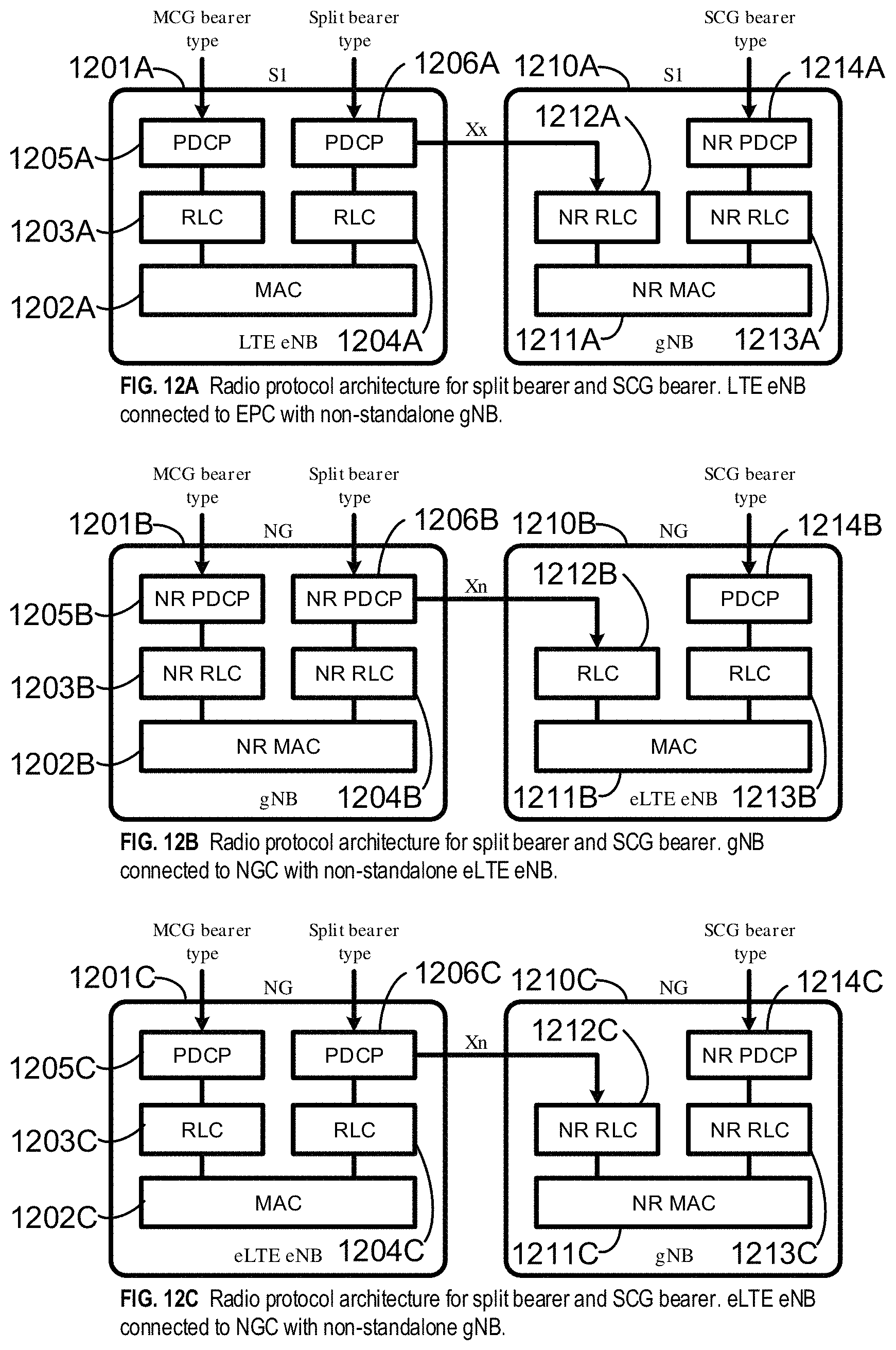
D00013

D00014

D00015
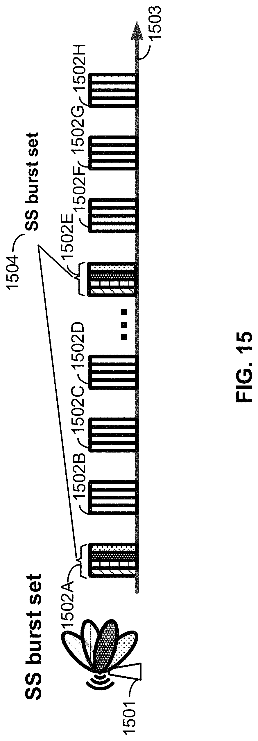
D00016
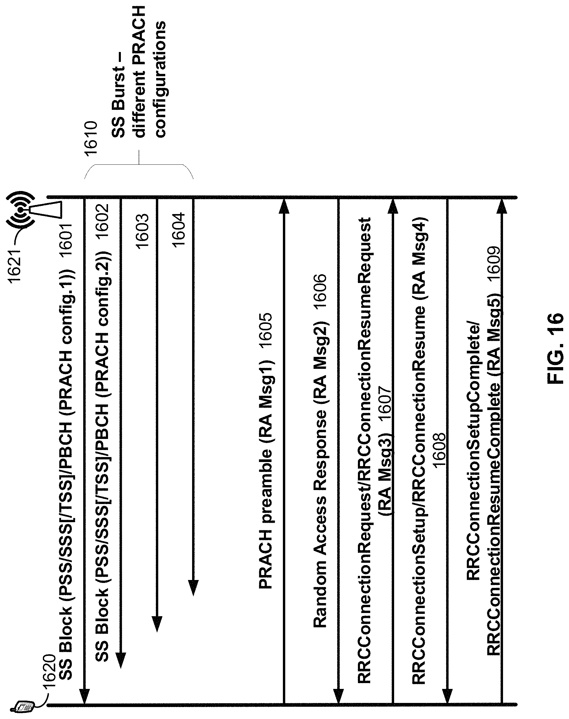
D00017
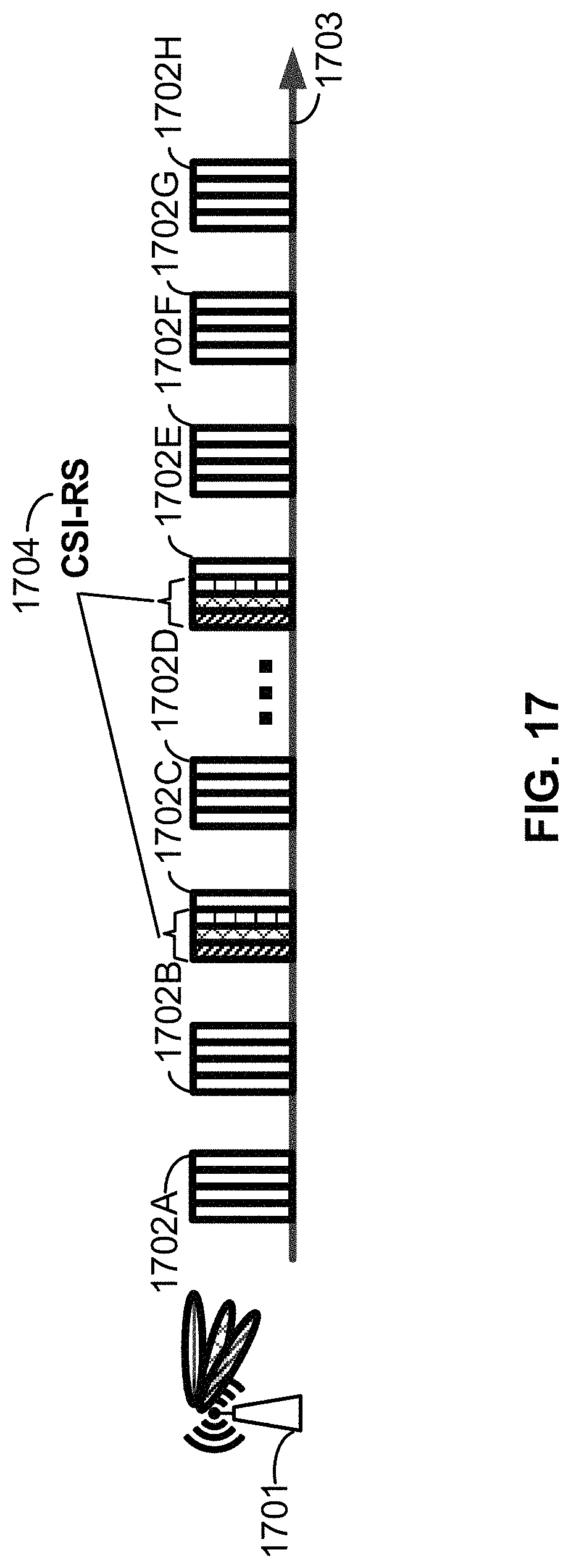
D00018
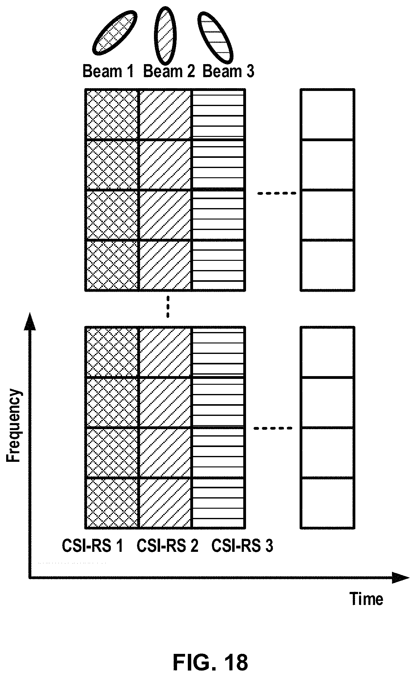
D00019
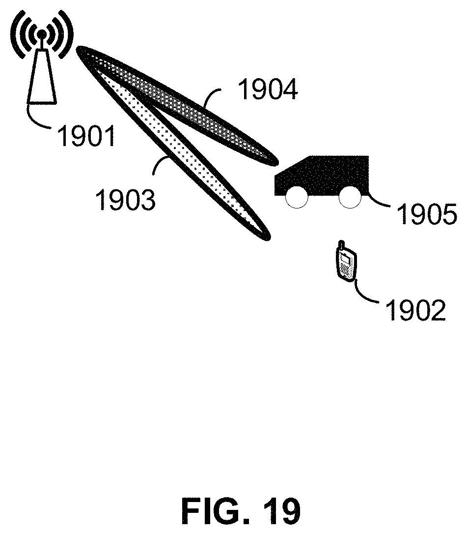
D00020

D00021

D00022
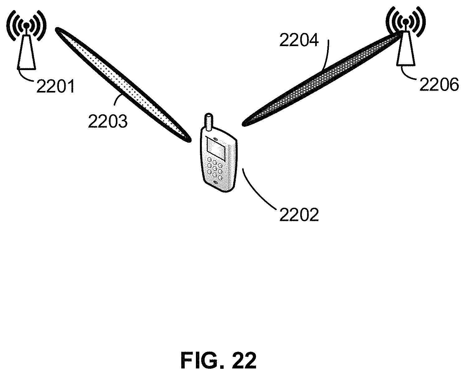
D00023

D00024
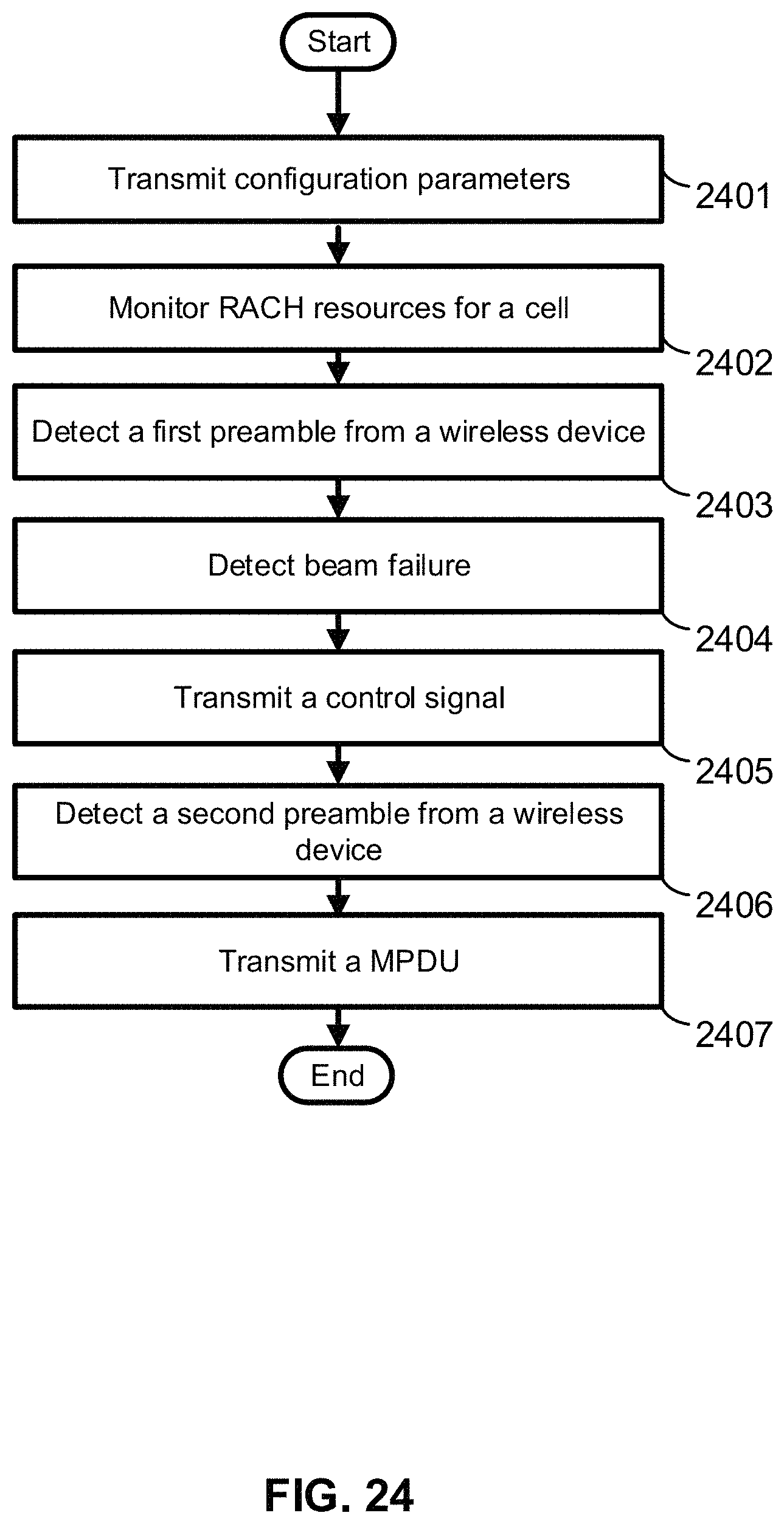
D00025
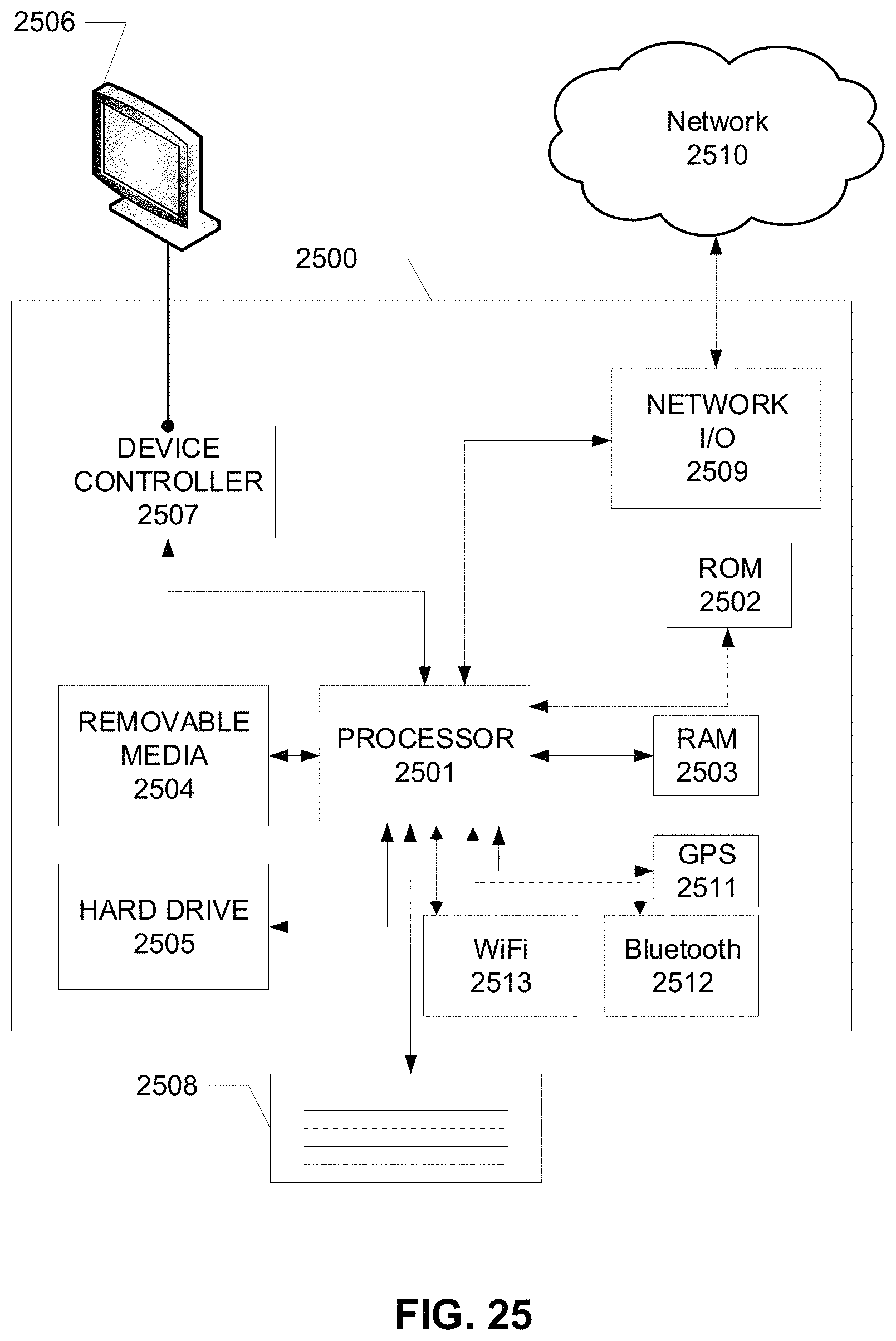
M00001
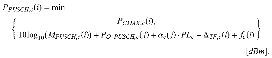
M00002
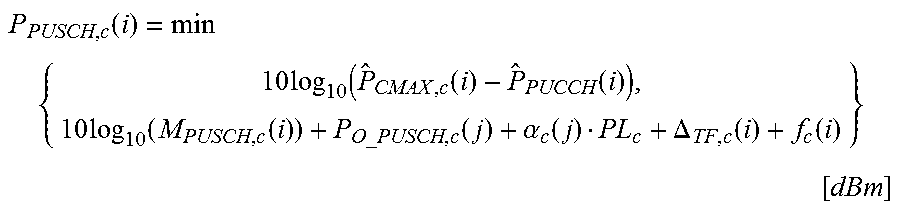
M00003

M00004

M00005

M00006

M00007

M00008

M00009

M00010

M00011

M00012

M00013

M00014

M00015

M00016

M00017

M00018

M00019

M00020

M00021
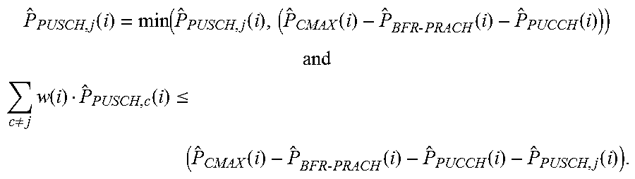
XML
uspto.report is an independent third-party trademark research tool that is not affiliated, endorsed, or sponsored by the United States Patent and Trademark Office (USPTO) or any other governmental organization. The information provided by uspto.report is based on publicly available data at the time of writing and is intended for informational purposes only.
While we strive to provide accurate and up-to-date information, we do not guarantee the accuracy, completeness, reliability, or suitability of the information displayed on this site. The use of this site is at your own risk. Any reliance you place on such information is therefore strictly at your own risk.
All official trademark data, including owner information, should be verified by visiting the official USPTO website at www.uspto.gov. This site is not intended to replace professional legal advice and should not be used as a substitute for consulting with a legal professional who is knowledgeable about trademark law.