Roller assembly of a cargo loading system
Dallum December 1, 2
U.S. patent number 10,850,843 [Application Number 16/400,820] was granted by the patent office on 2020-12-01 for roller assembly of a cargo loading system. This patent grant is currently assigned to Advanced Aircraft Roller Systems, Inc.. The grantee listed for this patent is Advanced Aircraft Roller Systems, Inc.. Invention is credited to John Dallum.


| United States Patent | 10,850,843 |
| Dallum | December 1, 2020 |
Roller assembly of a cargo loading system
Abstract
A cargo handling system that enables rollers to swivel without the need for the inclusion of metal thrust bearings. A method of assembling and retrofitting existing conventional type swivel caster style wheels is also provided.
| Inventors: | Dallum; John (Ramsey, MN) | ||||||||||
|---|---|---|---|---|---|---|---|---|---|---|---|
| Applicant: |
|
||||||||||
| Assignee: | Advanced Aircraft Roller Systems,
Inc. (Ramsey, MN) |
||||||||||
| Family ID: | 1000005213609 | ||||||||||
| Appl. No.: | 16/400,820 | ||||||||||
| Filed: | May 1, 2019 |
Prior Publication Data
| Document Identifier | Publication Date | |
|---|---|---|
| US 20190337622 A1 | Nov 7, 2019 | |
Related U.S. Patent Documents
| Application Number | Filing Date | Patent Number | Issue Date | ||
|---|---|---|---|---|---|
| 62666350 | May 3, 2018 | ||||
| Current U.S. Class: | 1/1 |
| Current CPC Class: | F16C 17/04 (20130101); B65G 67/00 (20130101); B64D 9/00 (20130101); B64D 2009/006 (20130101); F16C 2326/58 (20130101) |
| Current International Class: | B64D 9/00 (20060101); F16C 17/04 (20060101); B65G 67/00 (20060101) |
| Field of Search: | ;193/35MD,35SS ;198/782 |
References Cited [Referenced By]
U.S. Patent Documents
| 736027 | August 1903 | Sauer |
| 1305330 | June 1919 | Wolever et al. |
| 2258268 | October 1941 | Sparks et al. |
| 2572276 | October 1951 | Moe |
| 2672306 | March 1954 | Doolittle et al. |
| 2886156 | May 1959 | Halbron |
| 3257133 | June 1966 | Wight |
| 3293728 | December 1966 | Hill |
| 3711912 | January 1973 | Teske et al. |
| 3797082 | March 1974 | Brunes |
| 3815196 | June 1974 | Gotham et al. |
| 3913729 | October 1975 | Andrews |
| 4168771 | September 1979 | Krivec |
| 4203509 | May 1980 | Thompson et al. |
| 4213523 | July 1980 | Frost et al. |
| 4312444 | January 1982 | Mushovic |
| 4382637 | May 1983 | Blackburn |
| 4440295 | April 1984 | Blackwood-Murray et al. |
| 4681203 | July 1987 | Kornylak |
| 4766996 | August 1988 | Gibson |
| 4790421 | December 1988 | Gorges |
| 4838986 | June 1989 | Rhoades et al. |
| 4913277 | April 1990 | Zorgiebel |
| 4998497 | March 1991 | Nelson |
| 5217099 | June 1993 | Marcus et al. |
| 5381887 | January 1995 | Emmons |
| 5542900 | August 1996 | Burke |
| 5568858 | October 1996 | Thompson |
| 5655642 | August 1997 | Lawrence et al. |
| 5806131 | September 1998 | Tennant |
| 5893821 | April 1999 | Ando et al. |
| 6044963 | April 2000 | Lerch et al. |
| 6105249 | August 2000 | Ando et al. |
| 6113059 | September 2000 | Couillard |
| 6354424 | March 2002 | Rowles |
| 6516933 | February 2003 | Ledingham |
| 7771333 | August 2010 | Spiess et al. |
| 8109702 | February 2012 | Stegmiller et al. |
| 8430801 | April 2013 | Dallum et al. |
| 2003/0014833 | January 2003 | Saggio |
| 2006/0251510 | November 2006 | Gray |
| 2007/0237598 | November 2007 | Schulze |
| 2008/0217138 | September 2008 | Fourney |
| 2009/0151124 | June 2009 | Forrest |
| 2009/0324356 | December 2009 | Schulze et al. |
| 2010/0054889 | March 2010 | Stegmiller |
| 2016/0288359 | October 2016 | Patrick |
| 671076 | Nov 1965 | BE | |||
| 295 05 461.1 | Jul 1995 | DE | |||
| 0 683 438 | Nov 1995 | EP | |||
| 2 124 333 | Feb 1984 | GB | |||
| 2000-136287 | May 2000 | JP | |||
Other References
|
"Compressive Strength Testing of Plastics," [online], Dec. 1, 2007, matweb.com. cited by applicant . "Delrin.RTM. AF Blend" Properties, prior art as of May 13, 2018. cited by applicant. |
Primary Examiner: Bidwell; James R
Attorney, Agent or Firm: Merchant & Gould P.C.
Parent Case Text
CROSS-REFERENCE TO RELATED APPLICATION
The present application claims the benefit of U.S. Provisional Patent Application Ser. No. 62/666,350, filed May 3, 2018, which application is hereby incorporated by reference in its entirety.
Claims
What is Claimed is:
1. A roller assembly including: a base; a roller support bracket configured to rotate relative to the base about a vertical axis, wherein the base and roller support bracket cooperatively define an annular bearing pocket positioned between the base and the roller support bracket; a thrust bearing positioned at least partially within the bearing pocket, wherein the thrust bearing includes a nonmetallic construction; and an o-ring positioned between the base and the roller support bracket, wherein the o-ring is seated within an annular groove in the roller support bracket.
2. The roller assembly of claim 1, wherein the thrust bearing is constructed of a polymeric material.
3. The roller assembly of claim 1, wherein the thrust bearing is constructed of acetal.
4. The roller assembly of claim 1, wherein the thrust bearing is constructed of Delrin.RTM..
5. The roller assembly of claim 1, wherein the bearing pocket includes an inner guide surface and an outer guide surface.
6. The roller assembly of claim 1, wherein the bearing pocket includes an inner cylindrical guide surface and an outer cylindrical guide surface.
7. The roller assembly of claim 1, wherein the thrust bearing has a thickness T and the bearing pocket has a depth D, and wherein the thickness T of the thrust bearing is greater than the depth D of the bearing pocket.
8. The roller assembly of claim 7, wherein the o-ring has a diameter larger than the thrust bearing and is concentrically arranged with the thrust bearing.
9. The roller assembly of claim 8, wherein the o-ring projects from a surface of the roller support bracket a distance less than the difference between the thickness T of the thrust bearing and the depth D of the bearing pocket.
10. A method of retrofitting a conventional roller assembly including the steps of: separating a base from a roller support bracket; replacing a metal thrust bearing located between the base and the roller support bracket with an annular acetal disk, wherein the annular acetal disk is configured to be partially seated within a bearing pocket defined by an annular groove in the base; and reconnecting the base to the roller support bracket.
11. The method of claim 10, wherein the step of separating the base from the roller support bracket includes unbolting the roller support bracket from the base.
12. The method of claim 10, wherein the annular groove has a depth that is less than a thickness of the annular acetal disk.
13. An aircraft cargo handling system including: a unicaster swivel assembly that includes: a swivel frame configured to be secured to the floor of a cargo area in an aircraft; a cargo roller support bracket configured to rotate relative to the swivel frame about a vertical axis; a nonmetallic thrust bearing positioned between the swivel frame and the cargo roller support bracket; and an o-ring positioned between the swivel frame and the cargo roller support bracket, wherein the o-ring is seated within an annular groove in the cargo roller support bracket.
14. The aircraft cargo handling system of claim 13, wherein the swivel frame is configured to be secured to a track that is configured to be secured to the floor structure of an aircraft.
15. The aircraft cargo handling system of claim 13, wherein the swivel frame is configured to be secured to a caster panel that is configured to be secured to the floor of an aircraft.
Description
TECHNICAL FIELD
The present disclosure provides a maintenance free roller type caster assembly.
BACKGROUND
Cargo handling systems have numerous applications including, for example, conveying and securing cargo on the lower deck on passenger aircraft and on the main deck of freighter aircraft. Items that are shipped by air typically are loaded onto specially configured pallets, or into specially configured containers. In the air freight industry, these various pallets and containers are commonly referred to as Unit Load Devices (ULDs), which are available in various sizes, shapes and capacities. Additional information relating to cargo handling systems for aircraft can be found in U.S. Pat. No. 8,430,801; U.S. Pat. No. 7,771,333; U.S. Pat. No. 8,109,702, United States Patent Publication No. 2009/0324356; and United States Patent Publication No. US 2007/0237598, all of which are incorporated by reference herein in their entirety.
A typical cargo handling system consists of, among other components, conveyor rollers that facilitate movement of a ULD within an aircraft's cargo compartment. The deck of an aircraft cargo compartment typically includes a number of raised roller elements. These roller elements often include elongated roller trays that extend longitudinally along the length of the cargo deck, ball panel units, and the like. For example, roller trays typically include elongated rows of cylindrical rollers that extend in a fore and aft direction. Ball panel units include plates with upwardly protruding rotatable spherical balls or wheels that swivel about a vertical axis.
The ULDs sit atop these roller elements, and the roller elements facilitate rolling movement of the ULDs within the cargo compartment. The apex of these roller elements can form what is known in the art as the conveyor plane. The conveyor plane &so refers to a bottom plane on which a ULD (with a completely flat underside) traverses.
Metal thrust bearings are often used to enable the swiveling motion of the rollers. Over time, the metal thrust bearings require maintenance such as lubrication, etc. There exists a need for robust cargo handling systems requiring less maintenance.
SUMMARY
The present disclosure provides a cargo handling system that enables rollers to swivel without the need for the inclusion of metal thrust bearings. A method of assembling and retrofitting existing swivel caster style rollers is also provided.
BRIEF DESCRIPTION OF THE FIGURES
FIG. 1 is a roller assembly according to one embodiment of the present disclosure;
FIG. 2 is a roller assembly according to an alternative embodiment of the present disclosure;
FIG. 3 is an exploded assembly view of the roller assembly of FIG. 1;
FIG. 4 is a partial cross-sectional view of the roller assembly of FIG. 1;
FIGS. 5A-5J are perspective views of a component (thrust bearing) of the roller assembly of FIG. 1; and
FIG. 6 is a table with the material properties of a suitable material for use on the thrust bearing component of the roller assembly of FIG. 1.
DETAILED DESCRIPTION
Referring to FIGS. 1-6, the present invention is described in further detail. Referring to FIG. 1, an embodiment of a cargo handling system of the present disclosure is shown. In the depicted embodiment, the cargo handling system includes a guide that is in the form of a caster panel 2. The caster panel 2 is configured to be mounted to the floor of an aircraft cargo area. The caster panel 2 includes a plurality of apertures for receiving and securing roller assemblies 4 that are in the form of casters.
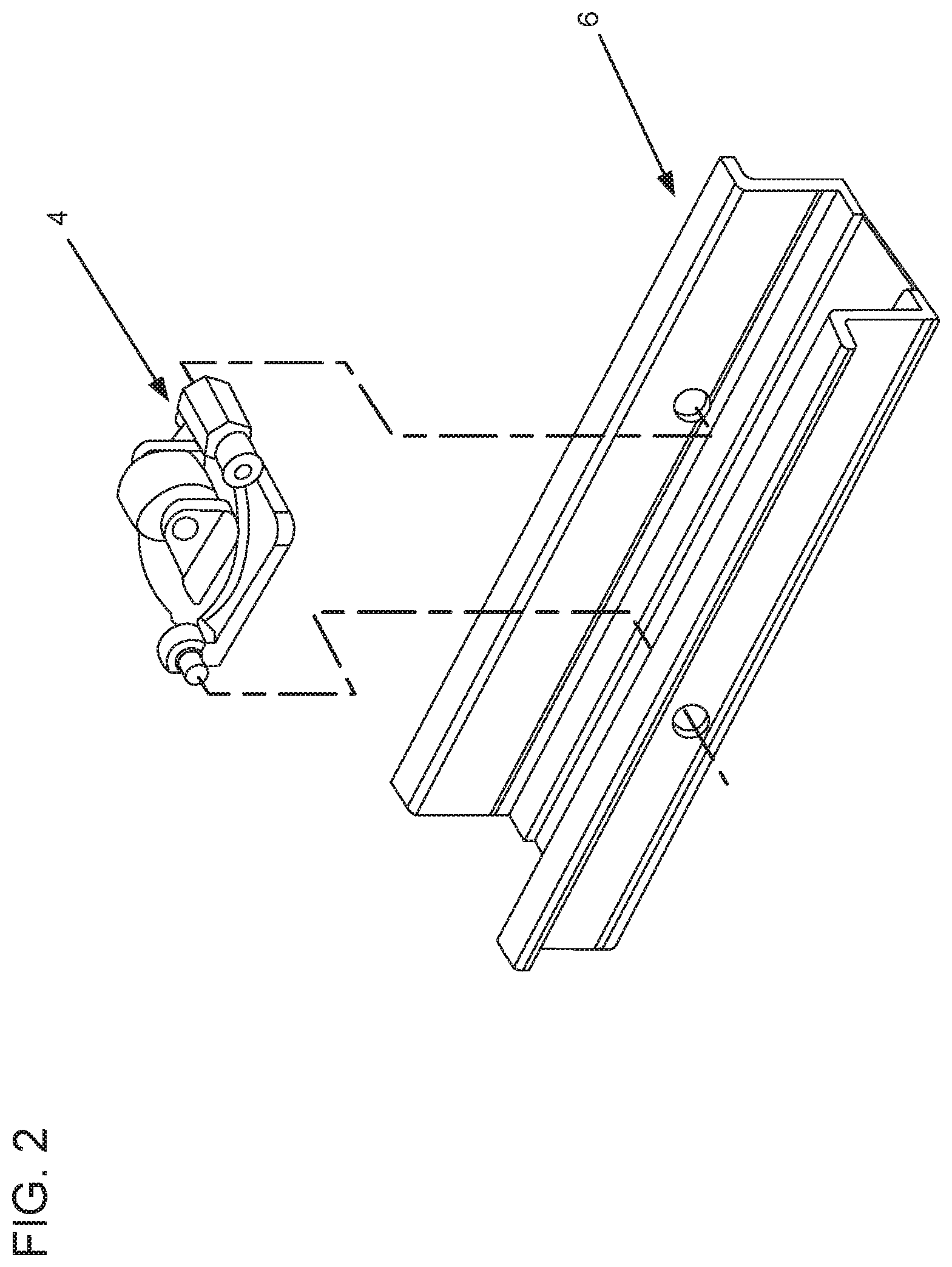
Referring to FIG. 2, an alternative embodiment of a cargo handling system of the present disclosure is shown. In the depicted embodiment, a roller assembly 4 is configured to be mounted to a channel/track 6. The channel 6 is configured to be mounted to or embedded into the floor of an aircraft cargo area. It should be appreciated that the caster panel 2 and the channel 6 could be secured to any surface in which cargo handling is desired. The present disclosure has applicability far beyond the aircraft context.
Referring to FIG. 3, an exploded assembly view of the roller assembly 4 is shown. In the depicted embodiment, the roller assembly 4 includes a base 14 and a roller support bracket 16. In the depicted embodiment, the roller support bracket 16 is configured to rotate relative to the base about a vertical axis. The base 14 and roller support bracket 16 swivel relative to each other. In the depicted embodiment, a bolt assembly 18 defines the vertical swivel axis.
In the depicted embodiment, the roller support bracket 16 is configured to support a roller 22 in a manner to allow the roller 22 to rotate about a horizontal axis. In the depicted embodiment, a bolt assembly 23 defines the horizontal rotational axis about which the roller 22 rotates.
In the depicted embodiment, the roller assembly 4 includes a nonmetallic thrust bearing 26 located between the base 14 and the roller support bracket 16. In the depicted embodiment, the thrust bearing 26 is positioned partially within a bearing pocket 28. In the depicted embodiment, the bearing pocket 28 is an annular recess in the base 14. In the depicted embodiment, a bearing pocket 28 includes an inner cylindrical guide surface 30 and an outer cylindrical guide surface 32. In the depicted embodiment, the thrust bearing 26 has a thickness T and the bearing pocket 28 has a depth D. According to one example embodiment, the thickness T of the thrust bearing 26 is greater than the depth D of the bearing pocket 28.
In the depicted embodiment, the roller assembly 4 includes an o-ring 34 positioned between the base 14 and the roller support bracket 16. In the depicted embodiment, the o-ring 34 has a diameter larger than the thrust bearing 26 and is concentrically arranged with the thrust bearing 26. In the depicted embodiment, the o-ring 34 is seated within an annular groove 36 in the roller support bracket 16. In the depicted embodiment, the o-ring 34 preferably projects from the surface of the roller support bracket 16 a distance less than the difference between the thickness T of the thrust bearing 26 and the depth D of the bearing pocket 28.
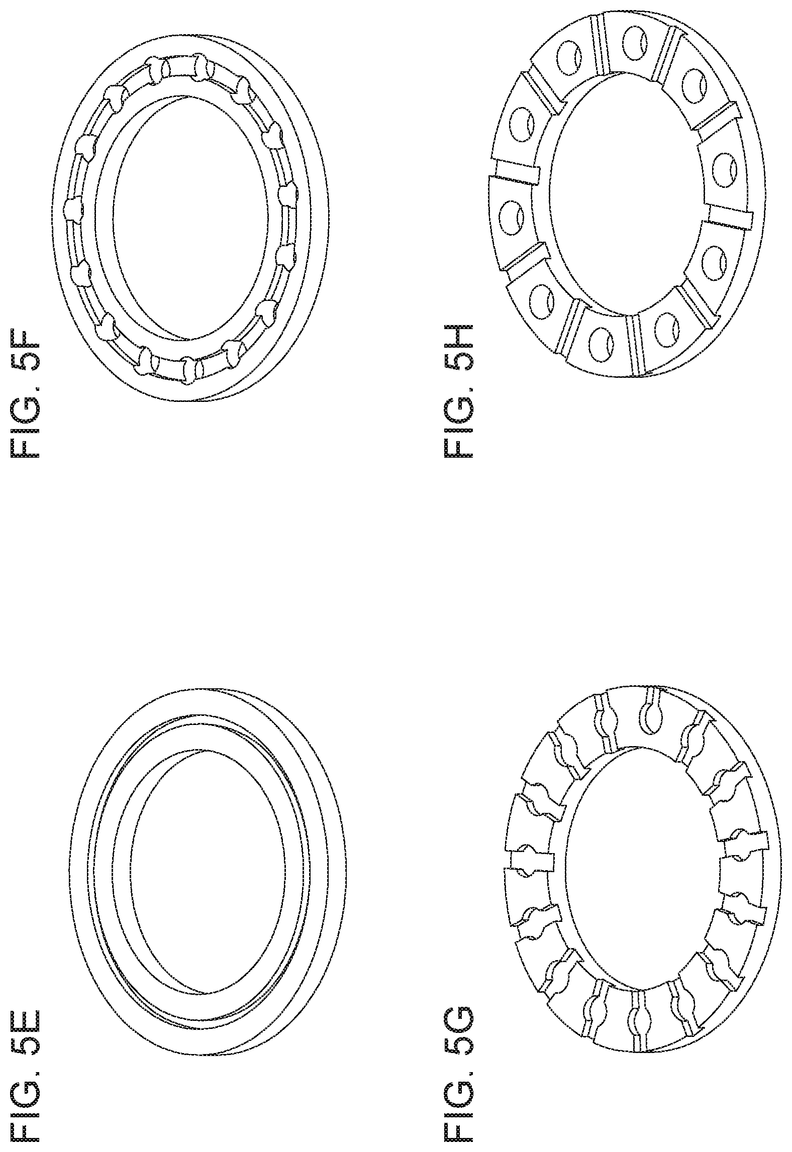
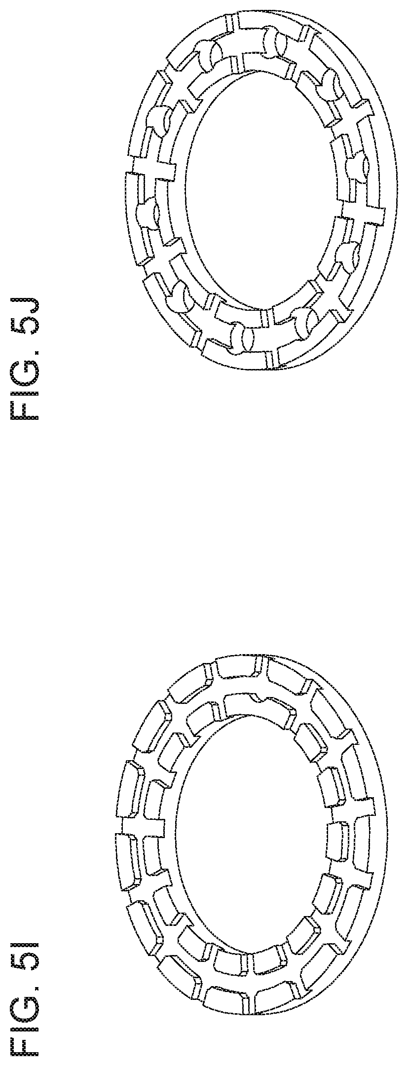
In the depicted embodiment, the thrust bearing 26 is nonmetallic. In the depicted embodiment, the thrust bearing 26 is constructed of plastic and includes acetal. In this particular embodiment, the entire thrust bearing 26 is constructed of Delrin.RTM.. FIG. 6 illustrates a table with the material properties of a suitable material (Delrin.RTM. AF blend) for the thrust bearing 26. It should be appreciated that many alternative constructions are possible including composite multi-material constructions. The structure and configuration of the thrust bearings 26 can also take a number of different embodiments. FIGS. 5A-5J depict some of the various thrust bearing configurations. In some depicted embodiments, the thrust bearing includes recesses, grooves, and channels in the upper and lower surfaces. These feature can be beneficial in providing a space for contaminates to collect, thereby preventing or limiting contaminates from collecting between the working surface of the thrust bearing and the surface that it slides against (e.g., the surface of the support bracket or base). It should be appreciated that many alternative configurations exist.
In one embodiment, the roller assembly 4 is particularly configured as part of an aircraft cargo handling system, and the roller assembly 4 takes the form of a unicaster swivel assembly. The base 14 is a swivel frame configured to be directly or indirectly (via tracks or a caster panel) secured to the floor of a cargo area in an aircraft, the roller support bracket 16 is a cargo roller support bracket 16 configured to rotate relative to the swivel frame about a vertical axis, and the thrust bearing 26 is a nonmetallic thrust bearing 26 positioned between the swivel frame and the cargo roller support bracket 16.
A method of retrofitting a roller assembly 4 is also provided. The method includes the steps of separating a base 14 from a roller support bracket 16, replacing a conventional metal thrust bearing located between the base 14 and the roller support bracket 16 with an annular acetal disk defining the thrust bearing 26 having features that are examples of inventive aspects in accordance with the present disclosure, and reconnecting the base 14 to the roller support bracket 16. In the above described method, the step of separating the base 14 from the roller support bracket 16 includes unbolting the roller support bracket 16 from the base 14. As discussed above, the acetal disk defining the inventive thrust bearing 26 can be configured to be partially seated within a bearing pocket 28 defined by an annular groove in the base 14. The annular groove can have a depth that is less than the thickness of the annular acetal disk defining the bearing 26.
The present disclosure may be embodied in other specific forms without departing from the spirit or essential attributes thereof; and it is, therefore, desired that the present embodiment be considered in all respects as illustrative and not restrictive, reference being made to the appended claims rather than to the foregoing description to indicate the scope of the invention.
* * * * *
D00000
D00001
D00002
D00003
D00004
D00005
D00006
D00007
D00008
XML
uspto.report is an independent third-party trademark research tool that is not affiliated, endorsed, or sponsored by the United States Patent and Trademark Office (USPTO) or any other governmental organization. The information provided by uspto.report is based on publicly available data at the time of writing and is intended for informational purposes only.
While we strive to provide accurate and up-to-date information, we do not guarantee the accuracy, completeness, reliability, or suitability of the information displayed on this site. The use of this site is at your own risk. Any reliance you place on such information is therefore strictly at your own risk.
All official trademark data, including owner information, should be verified by visiting the official USPTO website at www.uspto.gov. This site is not intended to replace professional legal advice and should not be used as a substitute for consulting with a legal professional who is knowledgeable about trademark law.