Linear ball guided voice coil motor for folded optic
Bachar , et al. November 24, 2
U.S. patent number 10,845,565 [Application Number 15/738,951] was granted by the patent office on 2020-11-24 for linear ball guided voice coil motor for folded optic. This patent grant is currently assigned to Corephotonics Ltd.. The grantee listed for this patent is Corephotonics Ltd.. Invention is credited to Gal Avivi, Gil Bachar, Ephraim Goldenberg, Itay Jerbi, Gal Shabtay, Itay Yedid.


View All Diagrams
| United States Patent | 10,845,565 |
| Bachar , et al. | November 24, 2020 |
Linear ball guided voice coil motor for folded optic
Abstract
Actuators for carrying and actuating a lens having a first optical axis, the lens receiving light folded from a second optical axis substantially perpendicular to the first optical axis, comprising first and second VCM engines coupled to the lens and first and second linear ball-guided rails operative to create movement of the lens in two substantially orthogonal directions upon actuation by respective VCM engines.
| Inventors: | Bachar; Gil (Tel-Aviv, IL), Yedid; Itay (Karme Yosef, IL), Shabtay; Gal (Tel-Aviv, IL), Goldenberg; Ephraim (Ashdod, IL), Avivi; Gal (Haifa, IL), Jerbi; Itay (Netanya, IL) | ||||||||||
|---|---|---|---|---|---|---|---|---|---|---|---|
| Applicant: |
|
||||||||||
| Assignee: | Corephotonics Ltd. (Tel Aviv,
IL) |
||||||||||
| Family ID: | 1000005202402 | ||||||||||
| Appl. No.: | 15/738,951 | ||||||||||
| Filed: | July 6, 2017 | ||||||||||
| PCT Filed: | July 06, 2017 | ||||||||||
| PCT No.: | PCT/IB2017/054088 | ||||||||||
| 371(c)(1),(2),(4) Date: | December 21, 2017 | ||||||||||
| PCT Pub. No.: | WO2018/007981 | ||||||||||
| PCT Pub. Date: | January 11, 2018 |
Prior Publication Data
| Document Identifier | Publication Date | |
|---|---|---|
| US 20190377155 A1 | Dec 12, 2019 | |
Related U.S. Patent Documents
| Application Number | Filing Date | Patent Number | Issue Date | ||
|---|---|---|---|---|---|
| 62359222 | Jul 7, 2016 | ||||
| Current U.S. Class: | 1/1 |
| Current CPC Class: | G02B 7/09 (20130101); H04N 5/2253 (20130101); H04N 5/2254 (20130101); G02B 27/646 (20130101) |
| Current International Class: | G02B 7/09 (20060101); H04N 5/225 (20060101); G02B 27/64 (20060101) |
References Cited [Referenced By]
U.S. Patent Documents
| 4199785 | April 1980 | McCullough et al. |
| 5005083 | April 1991 | Grage et al. |
| 5032917 | July 1991 | Aschwanden |
| 5041852 | August 1991 | Misawa et al. |
| 5051830 | September 1991 | von Hoessle |
| 5099263 | March 1992 | Matsumoto et al. |
| 5248971 | September 1993 | Mandl |
| 5287093 | February 1994 | Amano et al. |
| 5436660 | July 1995 | Sakamoto |
| 5444478 | August 1995 | Lelong et al. |
| 5459520 | October 1995 | Sasaki |
| 5657402 | August 1997 | Bender et al. |
| 5682198 | October 1997 | Katayama et al. |
| 5768443 | June 1998 | Michael et al. |
| 5926190 | July 1999 | Turkowski et al. |
| 5940641 | August 1999 | McIntyre et al. |
| 5982951 | November 1999 | Katayama et al. |
| 6101334 | August 2000 | Fantone |
| 6128416 | October 2000 | Oura |
| 6148120 | November 2000 | Sussman |
| 6208765 | March 2001 | Bergen |
| 6268611 | July 2001 | Pettersson et al. |
| 6549215 | April 2003 | Jouppi |
| 6611289 | August 2003 | Yu et al. |
| 6643416 | November 2003 | Daniels et al. |
| 6650368 | November 2003 | Doron |
| 6680748 | January 2004 | Monti |
| 6714665 | March 2004 | Hanna et al. |
| 6724421 | April 2004 | Glatt |
| 6738073 | May 2004 | Park et al. |
| 6741250 | May 2004 | Furlan et al. |
| 6750903 | June 2004 | Miyatake et al. |
| 6778207 | August 2004 | Lee et al. |
| 7002583 | February 2006 | Rabb, III |
| 7015954 | March 2006 | Foote et al. |
| 7038716 | May 2006 | Klein et al. |
| 7199348 | April 2007 | Olsen et al. |
| 7206136 | April 2007 | Labaziewicz et al. |
| 7248294 | July 2007 | Slatter |
| 7256944 | August 2007 | Labaziewicz et al. |
| 7305180 | December 2007 | Labaziewicz et al. |
| 7339621 | March 2008 | Fortier |
| 7346217 | March 2008 | Gold, Jr. |
| 7365793 | April 2008 | Cheatle et al. |
| 7411610 | August 2008 | Doyle |
| 7424218 | September 2008 | Baudisch et al. |
| 7509041 | March 2009 | Hosono |
| 7533819 | May 2009 | Barkan et al. |
| 7619683 | November 2009 | Davis |
| 7738016 | June 2010 | Toyofuku |
| 7773121 | August 2010 | Huntsberger et al. |
| 7809256 | October 2010 | Kuroda et al. |
| 7880776 | February 2011 | LeGall et al. |
| 7918398 | April 2011 | Li et al. |
| 7964835 | June 2011 | Olsen et al. |
| 7978239 | July 2011 | Deever et al. |
| 8115825 | February 2012 | Culbert et al. |
| 8149327 | April 2012 | Lin et al. |
| 8154610 | April 2012 | Jo et al. |
| 8238695 | August 2012 | Davey et al. |
| 8274552 | September 2012 | Dahi et al. |
| 8390729 | March 2013 | Long et al. |
| 8391697 | March 2013 | Cho et al. |
| 8400555 | March 2013 | Georgiev et al. |
| 8439265 | May 2013 | Ferren et al. |
| 8446484 | May 2013 | Muukki et al. |
| 8483452 | July 2013 | Ueda et al. |
| 8514491 | August 2013 | Duparre |
| 8547389 | October 2013 | Hoppe et al. |
| 8553106 | October 2013 | Scarff |
| 8587691 | November 2013 | Takane |
| 8619148 | December 2013 | Watts et al. |
| 8803990 | August 2014 | Smith |
| 8810714 | August 2014 | Seol et al. |
| 8896655 | November 2014 | Mauchly et al. |
| 8976255 | March 2015 | Matsuoto et al. |
| 9019387 | April 2015 | Nakano |
| 9025073 | May 2015 | Attar et al. |
| 9025077 | May 2015 | Attar et al. |
| 9041835 | May 2015 | Honda |
| 9137447 | September 2015 | Shibuno |
| 9185291 | November 2015 | Shabtay et al. |
| 9215377 | December 2015 | Sokeila et al. |
| 9215385 | December 2015 | Luo |
| 9270875 | February 2016 | Brisedoux et al. |
| 9286680 | March 2016 | Jiang et al. |
| 9344626 | May 2016 | Silverstein et al. |
| 9360671 | June 2016 | Zhou |
| 9369621 | June 2016 | Malone et al. |
| 9392188 | July 2016 | Shabtay et al. |
| 9413930 | August 2016 | Geerds |
| 9413984 | August 2016 | Attar et al. |
| 9420180 | August 2016 | Jin |
| 9438792 | September 2016 | Nakada et al. |
| 9485432 | November 2016 | Medasani et al. |
| 9578257 | February 2017 | Attar et al. |
| 9618748 | April 2017 | Munger et al. |
| 9681057 | June 2017 | Attar et al. |
| 9723220 | August 2017 | Sugie |
| 9736365 | August 2017 | Laroia |
| 9736391 | August 2017 | Du et al. |
| 9768310 | September 2017 | Ahn et al. |
| 9800798 | October 2017 | Ravirala et al. |
| 9851803 | December 2017 | Fisher et al. |
| 9894287 | February 2018 | Qian et al. |
| 9900522 | February 2018 | Lu |
| 9927600 | March 2018 | Goldenberg et al. |
| 2002/0005902 | January 2002 | Yuen |
| 2002/0021631 | February 2002 | Yokohama |
| 2002/0030163 | March 2002 | Zhang |
| 2002/0063711 | May 2002 | Park et al. |
| 2002/0075258 | June 2002 | Park et al. |
| 2002/0122113 | September 2002 | Foote |
| 2002/0167741 | November 2002 | Koiwai et al. |
| 2003/0030729 | February 2003 | Prentice et al. |
| 2003/0093805 | May 2003 | Gin |
| 2003/0160886 | August 2003 | Misawa et al. |
| 2003/0202113 | October 2003 | Yoshikawa |
| 2004/0008773 | January 2004 | Itokawa |
| 2004/0012683 | January 2004 | Yamasaki et al. |
| 2004/0017386 | January 2004 | Liu et al. |
| 2004/0027367 | February 2004 | Pilu |
| 2004/0061788 | April 2004 | Bateman |
| 2004/0141086 | July 2004 | Mihara |
| 2004/0174614 | September 2004 | Hovenky |
| 2004/0240052 | December 2004 | Minefuji et al. |
| 2005/0013509 | January 2005 | Samadani |
| 2005/0046740 | March 2005 | Davis |
| 2005/0157184 | July 2005 | Nakanishi et al. |
| 2005/0168834 | August 2005 | Matsumoto et al. |
| 2005/0200718 | September 2005 | Lee |
| 2006/0054782 | March 2006 | Olsen et al. |
| 2006/0056056 | March 2006 | Ahiska et al. |
| 2006/0102907 | May 2006 | Lee et al. |
| 2006/0125937 | June 2006 | LeGall et al. |
| 2006/0170793 | August 2006 | Pasquarette et al. |
| 2006/0175549 | August 2006 | Miller et al. |
| 2006/0187310 | August 2006 | Janson et al. |
| 2006/0187322 | August 2006 | Janson et al. |
| 2006/0187338 | August 2006 | May et al. |
| 2007/0024737 | February 2007 | Nakamura et al. |
| 2007/0126911 | June 2007 | Nanjo |
| 2007/0177025 | August 2007 | Kopet et al. |
| 2007/0188653 | August 2007 | Pollock et al. |
| 2007/0189386 | August 2007 | Imagawa et al. |
| 2007/0257184 | November 2007 | Olsen et al. |
| 2007/0285550 | December 2007 | Son |
| 2008/0017557 | January 2008 | Witdouck |
| 2008/0024614 | January 2008 | Li et al. |
| 2008/0025634 | January 2008 | Border et al. |
| 2008/0030592 | February 2008 | Border et al. |
| 2008/0030611 | February 2008 | Jenkins |
| 2008/0084484 | April 2008 | Ochi et al. |
| 2008/0117316 | May 2008 | Orimoto |
| 2008/0218611 | September 2008 | Parulski et al. |
| 2008/0218612 | September 2008 | Border et al. |
| 2008/0218613 | September 2008 | Janson et al. |
| 2008/0219654 | September 2008 | Border et al. |
| 2009/0086074 | April 2009 | Li et al. |
| 2009/0109556 | April 2009 | Shimizu et al. |
| 2009/0122195 | May 2009 | Van Baar et al. |
| 2009/0122406 | May 2009 | Rouvinen et al. |
| 2009/0128644 | May 2009 | Camp et al. |
| 2009/0219547 | September 2009 | Kauhanen et al. |
| 2009/0252484 | October 2009 | Hasuda et al. |
| 2009/0295949 | December 2009 | Ojala |
| 2009/0324135 | December 2009 | Kondo et al. |
| 2010/0013906 | January 2010 | Border et al. |
| 2010/0020221 | January 2010 | Tupman et al. |
| 2010/0060746 | March 2010 | Olsen et al. |
| 2010/0097444 | April 2010 | Lablans |
| 2010/0103194 | April 2010 | Chen et al. |
| 2010/0165131 | July 2010 | Makimoto et al. |
| 2010/0238327 | September 2010 | Griffith et al. |
| 2010/0283842 | November 2010 | Guissin et al. |
| 2010/0309322 | December 2010 | Ko et al. |
| 2010/0321494 | December 2010 | Peterson et al. |
| 2011/0058320 | March 2011 | Kim et al. |
| 2011/0064327 | March 2011 | Dagher et al. |
| 2011/0080487 | April 2011 | Venkataraman et al. |
| 2011/0128288 | June 2011 | Petrou et al. |
| 2011/0164172 | July 2011 | Shintani et al. |
| 2011/0229054 | September 2011 | Weston et al. |
| 2011/0234853 | September 2011 | Hayashi et al. |
| 2011/0234881 | September 2011 | Wakabayashi et al. |
| 2011/0235196 | September 2011 | Ke |
| 2011/0242286 | October 2011 | Pace et al. |
| 2011/0242355 | October 2011 | Goma et al. |
| 2011/0298966 | December 2011 | Kirschstein et al. |
| 2012/0026366 | February 2012 | Golan et al. |
| 2012/0062780 | March 2012 | Morihisa |
| 2012/0069235 | March 2012 | Imai |
| 2012/0075489 | March 2012 | Nishihara |
| 2012/0105579 | May 2012 | Jeon et al. |
| 2012/0154614 | June 2012 | Moriya et al. |
| 2012/0196648 | August 2012 | Havens et al. |
| 2012/0229663 | September 2012 | Nelson et al. |
| 2012/0249815 | October 2012 | Bohn et al. |
| 2012/0287315 | November 2012 | Huang et al. |
| 2012/0320467 | December 2012 | Baik et al. |
| 2013/0002928 | January 2013 | Imai |
| 2013/0016427 | January 2013 | Sugawara |
| 2013/0076922 | March 2013 | Shihoh et al. |
| 2013/0093842 | April 2013 | Yahata |
| 2013/0107382 | May 2013 | Chou |
| 2013/0113894 | May 2013 | Mirlay |
| 2013/0135445 | May 2013 | Dahi et al. |
| 2013/0182150 | July 2013 | Asakura |
| 2013/0201360 | August 2013 | Song |
| 2013/0202273 | August 2013 | Ouedraogo et al. |
| 2013/0235224 | September 2013 | Park et al. |
| 2013/0250150 | September 2013 | Malone et al. |
| 2013/0258044 | October 2013 | Betts-LaCroix |
| 2013/0270419 | October 2013 | Singh et al. |
| 2013/0278785 | October 2013 | Nomura et al. |
| 2013/0321668 | December 2013 | Kamath |
| 2014/0009631 | January 2014 | Topliss |
| 2014/0049615 | February 2014 | Uwagawa |
| 2014/0118584 | May 2014 | Lee et al. |
| 2014/0160311 | June 2014 | Hwang |
| 2014/0160331 | June 2014 | Hwang et al. |
| 2014/0192238 | July 2014 | Attar et al. |
| 2014/0192253 | July 2014 | Laroia |
| 2014/0218587 | August 2014 | Shah |
| 2014/0313316 | October 2014 | Olsson et al. |
| 2014/0362242 | December 2014 | Takizawa |
| 2015/0002683 | January 2015 | Hu et al. |
| 2015/0042870 | February 2015 | Chan et al. |
| 2015/0070781 | March 2015 | Cheng et al. |
| 2015/0092066 | April 2015 | Geiss et al. |
| 2015/0138381 | May 2015 | Ahn |
| 2015/0154776 | June 2015 | Zhang et al. |
| 2015/0162048 | June 2015 | Hirata et al. |
| 2015/0195458 | July 2015 | Nakayama et al. |
| 2015/0215516 | July 2015 | Dolgin |
| 2015/0237280 | August 2015 | Choi et al. |
| 2015/0242994 | August 2015 | Shen |
| 2015/0253543 | September 2015 | Mercado |
| 2015/0253647 | September 2015 | Mercado |
| 2015/0271471 | September 2015 | Hsieh et al. |
| 2015/0286033 | October 2015 | Osborne et al. |
| 2015/0316744 | November 2015 | Chen |
| 2015/0334309 | November 2015 | Peng et al. |
| 2016/0044250 | February 2016 | Shabtay et al. |
| 2016/0070088 | March 2016 | Koguchi |
| 2016/0154202 | June 2016 | Wippermann et al. |
| 2016/0154204 | June 2016 | Lim et al. |
| 2016/0212358 | July 2016 | Shikata |
| 2016/0241751 | August 2016 | Park |
| 2016/0291295 | October 2016 | Shabtay et al. |
| 2016/0295112 | October 2016 | Georgiev et al. |
| 2016/0301840 | October 2016 | Du et al. |
| 2016/0313569 | October 2016 | Ichihashi |
| 2016/0353008 | December 2016 | Osborne |
| 2016/0353012 | December 2016 | Kao et al. |
| 2017/0019616 | January 2017 | Zhu et al. |
| 2017/0187962 | June 2017 | Lee et al. |
| 2017/0214846 | July 2017 | Du et al. |
| 2017/0214866 | July 2017 | Zhu et al. |
| 2017/0242225 | August 2017 | Fiske |
| 2017/0289458 | October 2017 | Song et al. |
| 2018/0017844 | January 2018 | Yu et al. |
| 2018/0024329 | January 2018 | Goldenberg et al. |
| 2018/0059379 | March 2018 | Chou |
| 2018/0120674 | May 2018 | Avivi et al. |
| 2018/0150973 | May 2018 | Tang et al. |
| 2018/0241922 | August 2018 | Baldwin et al. |
| 2018/0295292 | October 2018 | Lee et al. |
| 101276415 | Oct 2008 | CN | |||
| 102739949 | Oct 2012 | CN | |||
| 103024272 | Apr 2013 | CN | |||
| 103841404 | Jun 2014 | CN | |||
| 1536633 | Jun 2005 | EP | |||
| 1780567 | May 2007 | EP | |||
| 2523450 | Nov 2012 | EP | |||
| S59191146 | Oct 1984 | JP | |||
| 04211230 | Aug 1992 | JP | |||
| H07318864 | Dec 1995 | JP | |||
| 08271976 | Oct 1996 | JP | |||
| 2003298920 | Oct 2003 | JP | |||
| 2004133054 | Apr 2004 | JP | |||
| 2004245982 | Sep 2004 | JP | |||
| 2005099265 | Apr 2005 | JP | |||
| 2006238325 | Sep 2006 | JP | |||
| 2007228006 | Sep 2007 | JP | |||
| 2007306282 | Nov 2007 | JP | |||
| 2008076485 | Apr 2008 | JP | |||
| 2011085666 | Apr 2011 | JP | |||
| 2013106289 | May 2013 | JP | |||
| 20090058229 | Jun 2009 | KR | |||
| 20100008936 | Jan 2010 | KR | |||
| 20140014787 | Feb 2014 | KR | |||
| 101477178 | Dec 2014 | KR | |||
| 101518826 | May 2015 | KR | |||
| 20150118012 | Oct 2015 | KR | |||
| 2010122841 | Oct 2010 | WO | |||
| 2014072818 | May 2014 | WO | |||
| WO2016/166730 | Oct 2016 | WO | |||
| 2017025822 | Feb 2017 | WO | |||
| 2017037688 | Mar 2017 | WO | |||
| WO2017/208090 | Dec 2017 | WO | |||
| 2018130898 | Jul 2018 | WO | |||
Other References
|
Statistical Modeling and Performance Characterization of a Real-Time Dual Camera Surveillance System, Greienhagen et al., Publisher: IEEE, 2000, 8 pages. cited by applicant . A 3MPixel Multi-Aperture Image Sensor with 0.7.mu.m Pixels in 0.11.mu.m CMOS, Fife et al., Stanford University, 2008, 3 pages. cited by applicant . Dual camera intelligent sensor for high definition 360 degrees surveillance, Scotti et al., Publisher: IET, May 9, 2000, 8 pages. cited by applicant . Dual-sensor foveated imaging system, Hua et al., Publisher: Optical Society of America, Jan. 14, 2008, 11 pages. cited by applicant . Defocus Video Matting, McGuire et al., Publisher: ACM SIGGRAPH, Jul. 31, 2005, 11 pages. cited by applicant . Compact multi-aperture imaging with high angular resolution, Santacana et al., Publisher: Optical Society of America, 2015, 10 pages. cited by applicant . Multi-Aperture Photography, Green et al., Publisher: Mitsubishi Electric Research Laboratories, Inc., Jul. 2007, 10 pages. cited by applicant . Multispectral Bilateral Video Fusion, Bennett et al., Publisher: IEEE, May 2007, 10 pages. cited by applicant . Super-resolution imaging using a camera array, Santacana et al., Publisher: Optical Society of America, 2014, 6 pages. cited by applicant . Optical Splitting Trees for High-Precision Monocular Imaging, McGuire et al., Publisher: IEEE, 2007, 11 pages. cited by applicant . High Performance Imaging Using Large Camera Arrays, Wilburn et al., Publisher: Association for Computing Machinery, Inc., 2005, 12 pages. cited by applicant . Real-time Edge-Aware Image Processing with the Bilateral Grid, Chen et al., Publisher: ACM SIGGRAPH, 9 pages. cited by applicant . Superimposed multi-resolution imaging, Carles et al., Publisher: Optical Society of America, 2017, 13 pages. cited by applicant . Viewfinder Alignment, Adams et al., Publisher: EUROGRAPHICS, 2008, 10 pages. cited by applicant . Dual-Camera System for Multi-Level Activity Recognition, Bodor et al., Publisher: IEEE, Oct. 2014, 6 pages. cited by applicant . Engineered to the task: Why camera-phone cameras are different, Giles Humpston, Publisher: Solid State Technology, Jun. 2009, 3 pages. cited by applicant . Office Action in related EP patent application 17823744.2, dated May 9, 2019. 4 Pages. cited by applicant . Office Action in related KR patent application 10-2017-7037183, dated May 18, 2018. cited by applicant . International Search Report and Written Opinion issued in related PCT patent application PCT/IB2017/054088 dated Dec. 4, 2017. 8 pages. cited by applicant. |
Primary Examiner: Carrasquillo; Jorge L
Assistant Examiner: Imtiaz; Zoheb S
Attorney, Agent or Firm: Nathan & Associates Nathan; Menachem
Parent Case Text
CROSS REFERENCE TO RELATED APPLICATIONS
This application is a 371 application from international patent application PCT/IB2017/054088 and is related to and claims priority from U.S. Provisional Patent Application No. 62/359,222, filed Jul. 7, 2016, which is incorporated herein by reference in its entirety.
Claims
What is claimed is:
1. A folded camera, comprising: a) a lens having a first optical axis and held in a lens holder, the lens receiving light folded from an optical path along a second optical axis that is substantially perpendicular to the first optical axis; b) an optical path folding element (OPFE) that folds the light from the optical path along the second optical axis to an optical path along the first optical axis; c) an image sensor; and d) an actuator for carrying and actuating the lens holder holding the lens, the actuator comprising: a first voice coil motor (VCM) engine coupled to the lens holder, a second VCM engine coupled to the lens holder, a first linear ball-guided rail operative to create a first movement of the lens holder upon actuation by the first VCM engine, wherein the first movement is in a first direction parallel to the first optical axis, and a second linear ball-guided rail operative to create a second movement of the lens holder upon actuation by the second VCM engine, wherein the second movement is in a second direction that is substantially perpendicular to the first optical axis and to the second optical axis.
2. The folded camera of claim 1, wherein the first movement is for focus and wherein the second movement is for optical image stabilization.
3. The folded camera of claim 1, wherein the actuator further comprises a middle moving frame that includes at least one groove in the first direction and at least one groove in the second direction.
4. The folded camera of claim 1, wherein the lens holder and the lens are made as one part.
5. The folded camera of claim 1, wherein each of the first and second linear ball-guided rails includes a pair of grooves having at least one ball located therebetween.
6. The folded camera of claim 1, wherein the first and second VCM engines include respective first and second VCM magnets.
7. The folded camera of claim 3, wherein the actuator further comprises a static base, wherein the lens holder is movable only along the first direction with respect to the middle moving frame and wherein the middle moving frame is movable only along the second direction with respect to the static base.
8. The folded camera of claim 3, wherein the actuator further comprises a static base, wherein the lens holder is movable only along the second direction with respect to the middle moving frame and wherein the middle moving frame is movable only along the first direction with respect to the static base.
9. The folded camera of claim 6, wherein the first and second VCM magnets are fixedly attached to the lens holder.
10. The folded camera of claim 6, wherein the first VCM magnet is fixedly attached to the lens holder and wherein the second VCM magnet is fixedly attached to the moving frame.
11. The folded camera of claim 6, wherein the first VCM magnet is fixedly attached to the moving frame, and wherein the second VCM magnet is fixedly attached to the lens holder.
12. The folded camera of claim 6, wherein the first VCM engine and the second VCM engine include respective first and second VCM coils mechanically coupled to the static base.
13. The folded camera of claim 6, wherein the actuator further comprises at least one ferromagnetic yoke attached to the static base and used to pull the first VCM magnet in order to prevent both the first and the second linear ball-guided rail from coming apart.
14. The folded camera of claim 6, wherein the actuator further comprises at least one ferromagnetic yoke attached to the static base and used to pull the second VCM magnet in order to prevent both the first and the second linear ball-guided rail from coming apart.
15. The folded camera of claim 12, wherein the first and second VCM coils and the first and second VCM magnets are respectively separated by a constant distance.
16. The folded camera of claim 6, wherein the actuator further comprises a first position sensor and a second position sensor for measuring a position of the lens upon the movement in the first and second directions, respectively.
17. The folded camera of claim 16, wherein the first and second position sensors are Hall bar position sensors operative to measure the magnetic field of the first and the second VCM magnets, respectively.
18. The folded camera of claim 1, wherein the OPFE is tiltable around the second direction by a rotational spring based mechanism.
19. The folded camera of claim 1, wherein the OPFE is tiltable around the second direction by a rotational ball based mechanism.
20. The folded camera of claim 1, included together with an upright camera in a dual-aperture camera.
Description
FIELD
Embodiments disclosed herein relate in general to actuating mechanisms ("actuators") and in particular to voice coil motor (VCM) actuators for digital cameras.
BACKGROUND
High-end digital camera modules, and specifically cellphone (e.g. smartphone) digital cameras include mechanisms that enable advanced optical function such as focus or optical image stabilization (OIS). Such mechanisms may actuate (e.g. displace, shift or tilt) an optical element (e.g. lens, image sensor, mirror) to create the desired optical function. A commonly used actuator is based on voice coil motor (VCM) technology. In VCM technology, a permanent (or "fixed") magnet and a coil are used to create actuation force. The coil is positioned in the vicinity of the magnetic field of the fixed magnet. Upon driving current in the coil, a Lorentz force is created on the coil, an in return an equal counter-force is applied on the magnet. The magnet or the coil is rigidly attached to an optical element to construct an actuated assembly. The actuated assembly is then moved by the magnetic Lorenz force. Henceforth, in this description, a VCM will be referred to also as "VCM engine" and an actuator including such a VCM (or VCM engine) will be referred to as to as "VCM actuator" or simply "actuator".
In addition to the magnetic force, a mechanical rail is known to set the course of motion for the optical element. The mechanical rail keeps the motion of the lens in a desired path, as required by optical needs. A typical mechanical rail is known in the art as "spring-guided rail", in which a spring or set of springs is used to set the motion direction. A VCM that includes a spring-guided rail is referred to as a "spring-guided VCM". For example, US patent application No. 20110235196 discloses a lens element shifted in a linear spring rail to create focus. For example, international patent application PCT/IB2016/052179 discloses the incorporation and use of a spring guided VCM in a folded camera structure ("FCS"--also referred to simply as "folded camera"). The disclosure teaches a lens element shifted to create focus and OIS and an optical path folding element (OPFE) shifted in a rotational manner to create OIS. Also, PCT/IB2016/052179 teaches AF+OIS in a folded actuator where the actuator dos not add to the module height.
Another typical mechanical rail is known in the art a "ball-guided rail", see e.g. U.S. Pat. No. 8,810,714. With a ball-guided rail, the lens is bound to move in the desired direction by set of balls confined in a groove (also referred to as "slit"). A VCM that includes a ball-guided rail is referred to as a "ball-guided VCM". A ball-guided VCM has several advantages over a spring-guided VCM. These include: (1) lower power consumption, because in a spring-guided VCM the magnetic force has to oppose a spring mechanical force, which does not exist in a ball-guided VCM, and (2) higher reliability in drops that may occur during the life-cycle of a camera that includes the VCM. The actuation method in U.S. Pat. No. 8,810,714 is designed for a standard non-folded lens, where the lens optical axis is directly pointed at the object to be photographed and cannot be used in a folded camera.
In view of the above, there is a need for, and it would be advantageous to have a linear ball guided VCM inside a folded camera to reduce the folded camera dimensions, in particular camera height and/or width. In addition, there is a need to show such a structure in a combination with various actuation mechanisms for the OPFEs in these cameras.
SUMMARY
Aspects of embodiments disclosed herein relate to VCMs to actuators including such VCMs, the actuators having linear ball-guided rails for AF and OIS in a folded camera, and to digital cameras, and in particular to cameras with folded optics that incorporate such VCMs.
In some exemplary embodiments there is provided an actuator for carrying and actuating a lens holder with a lens, the lens having a first optical axis, the lens receiving light folded from an optical path along a second optical axis that is substantially perpendicular to the first optical axis, the actuator comprising a first VCM engine coupled to the lens holder, a second VCM engine coupled to the lens holder, a first linear ball-guided rail operative to create a first movement of the lens holder upon actuation by the first VCM engine, wherein the first movement is in a first direction parallel to the first optical axis, and a second linear ball-guided rail operative to create a second movement of the lens holder upon actuation by the second VCM engine, wherein the second movement is in a second direction that is substantially perpendicular to the first optical axis and to the second optical axis.
In an exemplary embodiment, the first movement is for focus and the second movement is for OIS.
In an exemplary embodiment, an actuator further comprises a middle moving frame that includes at least one groove in the first direction and at least one groove in the second direction.
In an exemplary embodiment, the lens holder and the lens are made as one part.
In an exemplary embodiment, each of the first and second linear ball-guided rails includes a pair of grooves having at least one ball located therebetween.
In an exemplary embodiment, the first and second VCM engines include respective first and second VCM magnets.
In an exemplary embodiment, an actuator further comprises a static base, wherein the lens holder is movable only along the first direction with respect to the middle moving frame and wherein the middle moving frame is movable only along the second direction with respect to the static base.
In an exemplary embodiment, an actuator further comprises a static base, wherein the lens holder is movable only along the second direction with respect to the middle moving frame and wherein the middle moving frame is movable only along the first direction with respect to the static base.
In an exemplary embodiment, the first and second VCM magnets are fixedly attached to the lens holder.
In an exemplary embodiment, the first VCM magnet is fixedly attached to the lens holder and the second VCM magnet is fixedly attached to the moving frame.
In an exemplary embodiment, the first VCM magnet is fixedly attached to the moving frame, and the second VCM magnet is fixedly attached to the lens holder.
In an exemplary embodiment, the first VCM engine and the second VCM engine include respective first and second VCM coils mechanically coupled to the static base.
In an exemplary embodiment, an actuator further comprises at least one ferromagnetic yoke attached to the static base and used to pull the first VCM magnet in order to prevent both the first and the second linear ball-guided rail from coming apart.
In an exemplary embodiment, an actuator further comprises at least one ferromagnetic yoke attached to the static base and used to pull the first VCM magnet or the second VCM magnet in order to prevent both the first and the second linear ball-guided rail from coming apart.
In an exemplary embodiment, an actuator further comprises at least one ferromagnetic yoke attached to the static base and used to pull the second VCM magnet in order to prevent both the first and the second linear ball-guided rail from coming apart.
In an exemplary embodiment, the first and second VCM coils and the first and second VCM magnets are respectively separated by a constant distance.
In an exemplary embodiment, an actuator further comprises a first position sensor and a second position sensor for measuring a position of the lens upon the movement in the first and second directions, respectively.
In an exemplary embodiment, the first and second position sensors are Hall bar position sensors operative to measure the magnetic field of the first and the second VCM magnets, respectively.
In some exemplary embodiments, any of the actuators above may be included in a folded camera together with an OPFE that folds the light from the optical path along the second optical axis to an optical path along the first optical axis, wherein the OPFE is tiltable around the second direction by a spring based mechanism or a ball based mechanism.
In some exemplary embodiments, the folded camera is included together with an upright camera in a dual-aperture camera.
BRIEF DESCRIPTION OF THE DRAWINGS
Aspects, embodiments and features disclosed herein will become apparent from the following detailed description when considered in conjunction with the accompanying drawings, in which:
FIG. 1A shows an isomeric view of a linear ball guided VCM actuator according to an exemplary embodiment disclosed herein;
FIG. 1B shows the VCM actuator of FIG. 1A in an exploded view;
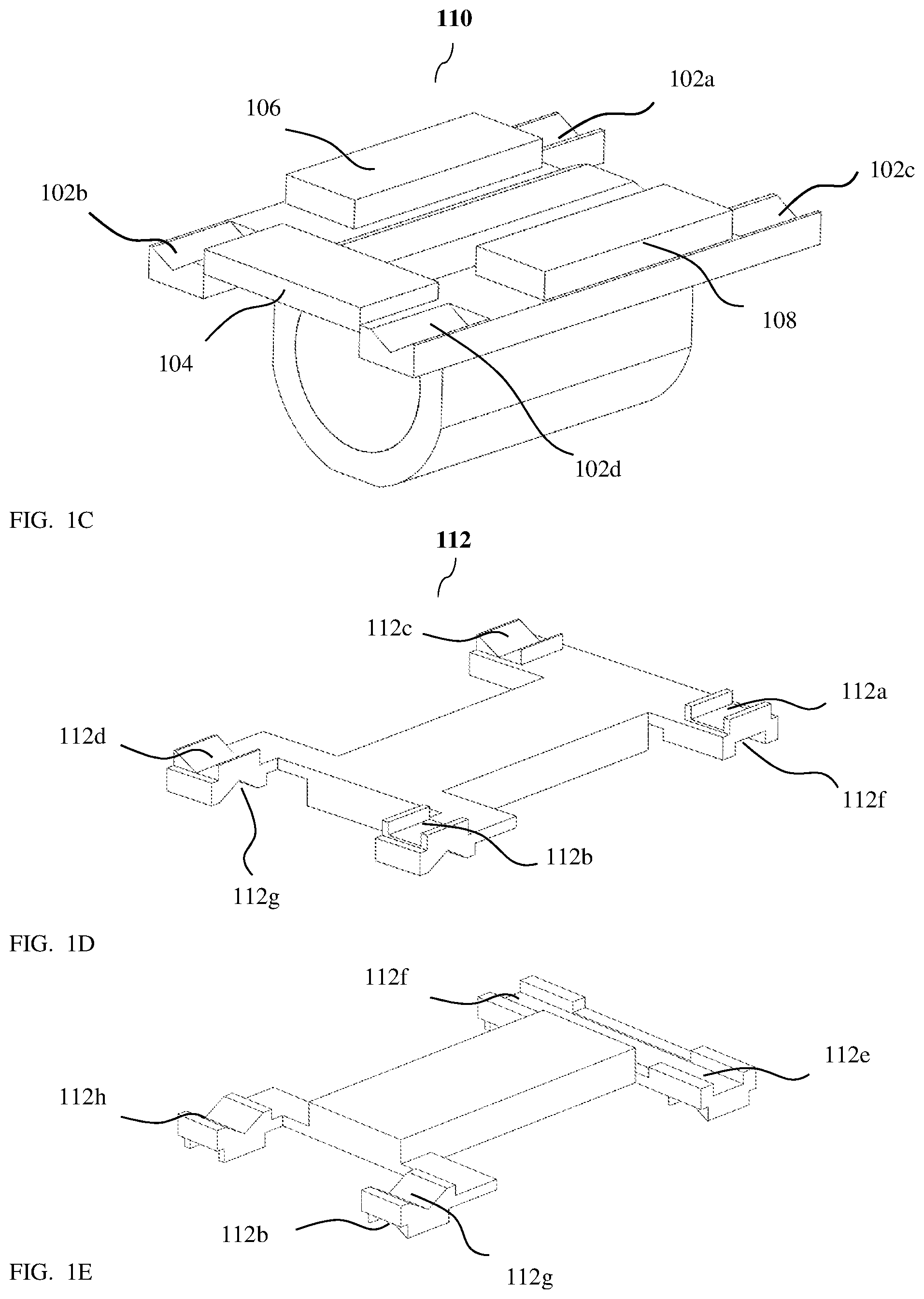
FIG. 1C shows a top actuated sub-assembly of the VCM actuator from a bottom view;
FIG. 1D shows a middle moving frame of the VCM actuator from a top view;
FIG. 1E shows a middle moving frame of the VCM actuator from a bottom view;
FIG. 1F shows a base of the VCM actuator in isometric view;
FIG. 1G shows an EM sub-assembly of the VCM actuator in isometric view;
FIG. 1H shows an isomeric view of a linear ball guided VCM actuator according to another exemplary embodiment;
FIG. 1I shows the VCM actuator of FIG. 1H in an exploded view;
FIG. 1J shows an isomeric view of a linear ball guided VCM actuator according to yet another exemplary embodiment;
FIG. 1K shows the VCM actuator of FIG. 1J in an exploded view;
FIG. 2A shows an embodiment of a folded camera that includes an actuator disclosed herein;
FIG. 2B shows an embodiment of a folded camera that includes an actuator disclosed herein and an OPFE rotated by one embodiment of a rotational spring based mechanism;
FIG. 2C shows an embodiment of a folded camera that includes an actuator disclosed herein and an OPFE rotated by another embodiment of a rotational ball based mechanism;
FIG. 3 shows an embodiment of a dual-camera that includes a folded camera as in FIG. 2C together with a non-folded (up right) camera.
DETAILED DESCRIPTION
FIG. 1A shows an isomeric view of a linear ball guided VCM actuator 100 according to an exemplary embodiment disclosed herein. FIG. 1B shows actuator 100 in an exploded view. Actuator 100 enables the shift of a lens 150 having an optical axis 160 (also referred to as "first optical axis") in two directions in a plane (i.e. the X-Y plane in the shown figures), as described below: AF operation in a direction 162 and OIS operation in a direction 164. Actuator 100 has exemplary length/width/height dimensions in the range of 3-40 mm, i.e. actuator 100 can be contained in a box with dimension of 3.times.3.times.3 mm.sup.3 to 40.times.40.times.40 mm.sup.3. The description continues with reference to a coordinate system XYZ shown in FIGS. 1A and 1B as well as in a number of other figures.
In actuator 100, lens 150 is positioned and held in a lens holder (or lens carrier) 102 that fits the shape of lens 150. In some embodiments, lens holder 102 and lens 150 may be a single part. In some embodiments, they may be separate parts. In the following description and claims, the term "lens holder" may be describing a lens holder only, or a unified part (component) that includes a lens holder and a lens. Lens holder 102 may be made, for example, by plastic molding, or alternatively by other methods. Three magnets 104, 106 and 108 are fixedly attached (e.g. glued) to lens holder 102 from below (in the negative Z direction in the figure). The assembly of lens holder 102 and magnets 104-108 will be referred to henceforth as "top actuated sub-assembly" 110. FIG. 1C shows top actuated sub-assembly 110 from a bottom view. Lens holder 102 includes four grooves, 102a-d. Grooves 102a-d are parallel to each other and are along the Y-axis. Grooves 102a-d are used to guide top actuated sub-assembly 110 along the Y direction.
Actuator 100 further includes a middle moving frame 112, typically made of plastic. FIGS. 1D and 1E show middle moving frame 112 from top and bottom views, respectively. Middle moving frame 112 includes eight grooves 112a-h, four grooves 112a-d on a top surface of adaptor 112 along the Y direction and four grooves 112e-h on a bottom surface of adaptor 112 are along the X direction. Top actuated sub-assembly 110 is positioned on top of middle moving frame 112 such that grooves 112a-d are just below and parallel to grooves 102a-d, respectively.
In the embodiment shown, four balls 114a-d are positioned on top of grooves 112a-d (one ball on top of each groove) such that balls 114a-d space apart lens holder 102 and middle moving frame 112 and prevent the two parts from touching each other. In other embodiments, actuator 100 may have more than one ball on top each groove 112a-d, for example up to 7 balls per groove. Balls 112a-d may be made from Alumina or another ceramic material, from a metal or from a plastic material. Typical ball diameters may be in the range of 0.3-1 mm. Other ball sizes and positioning considerations may be as in co-owned international PCT patent application PCT/IB2017/052383 titled "Rotational Ball Guided Voice Coil Motor".
Since lens holder 102 and middle moving frame 112 are exemplarily plastic molded, there is some tolerance allowed in part dimensions, typically a few tens of microns or less for each dimension. This tolerance may lead to misalignment of position between adjacent (facing) grooves 102a-102b-112a-112b and\or 102c-102d-112c-112d. To better align the grooves, grooves 102a-d, 112a-b may be V-shaped, i.e. have a V cross-section shape to ensure ball positioning, while grooves 112c-d may have a wider, rectangular cross-section. Grooves 102a-b and 112a-b are aligned during assembly, while the alignment of grooves 102c-d and 112c-d has a small freedom allowed by the rectangular cross section.
The assembly of top actuated sub-assembly 110, balls 114a-d, and middle moving frame 112 will be referred to henceforth as "bottom actuated sub-assembly" 120.
Actuator 100 further includes a base 122, typically made of plastic (FIG. 1B and FIG. 1F). Base 122 is molded with four grooves 122a-d along the X direction. Bottom actuated sub-assembly 120 is positioned on the top of base 122 such that grooves 122a-d are parallel to grooves 112e-h respectively. In the embodiment shown, base 122 only serves as part of actuator 100. In other embodiments, the base plastic molding may extend to serve for other purposes, such as a base for an actuator associated with a prism, to hold a camera sensor, to hold a shield, to prevent stray light and dust from reaching image sensor, etc.
Four balls 124a-d are positioned on top of grooves 122a-d (one ball on top of each groove) such that balls 124a-d space middle moving frame 112 apart from base 122 and prevent the two parts from touching each other. In other embodiments, actuator 100 may have more than one ball on top each groove 122a-d, for example up to 7 balls per groove. The size, material and other considerations related to balls 124a-d are similar to those of balls 114a-d.
Actuator 100 further includes three metallic ferromagnetic yokes 130, 132 and 134 fixedly attached (e.g. glued) to base 122 from above (positive Z direction in the figure) such each yoke is positioned below a respective one of magnets 104, 106 and 108. In other embodiments, ferromagnetic yokes 130, 132 and 134 may be fixedly attached to base 122 from below. Each yoke pulls its respective magnet by magnetic force in the negative Z direction, and thus all yokes prevent both top actuated sub-assembly 110 and bottom actuated sub-assembly 120 from detaching from base 122. Balls 114a-d prevent top actuated sub-assembly 110 from touching middle moving frame 112 and balls 124a-d prevent bottom actuated sub-assembly 120 from touching base 122. Both top actuated sub-assembly 110 and bottom actuated sub-assembly 120 are thus confined along the Z-axis and do not move in positive or negative Z directions. The groove and ball structure further confines top actuated sub-assembly 110 to move only along the Y-axis and bottom actuated sub-assembly 120 to move only along the X-axis.
Actuator 100 further includes an electro-magnetic (EM) sub-assembly 140, see FIG. 1B and FIG. 1G. EM sub-assembly 140 includes three coils 142, 144 and 146, two Hall bar elements 148 and 150 and a PCB 152. Coils 142-146 and Hall bar elements 148-150 are soldered (each one separately) to PCB 152. Coils 142-146 have exemplarily each a "stadium" shape and typically include a few tens of coil windings (i.e. in a non-limiting range of 50-250), with a typical resistance of 10-30 ohm. PCB 152 allows sending input and output currents to coils 142-146 and to Hall bar elements 148-126, the currents carrying both power and electronic signals needed for operation. PCB 152 may be connected electronically to the external camera by wires (not shown). EM sub-assembly 140 is positioned between magnets 104-108 and yokes 130-134, such that each coil 142-146 is positioned between a respective one of magnets 104-108 and a respective one of yokes 130-134. Upon driving a current in a coil (e.g. coil 142), a Lorentz force is created on the respective magnet (i.e. magnet 104); a current in a clockwise direction will create force in the positive Y direction, while a current in counter clockwise direction will create a force in the negative Y direction. Similarly, driving a current in coils 144 or 146 will create a respective Lorentz force on magnets 106 or 108; a current in a clockwise direction will create force in the positive X direction, while a current in a counter clockwise direction will create a force in the negative X direction. A full magnetic scheme (e.g. fixed magnets 130-134 pole direction) is described in detail for example in co-owned patent application PCT/IB2016/052179, and is known in the art.
Hall bar element 148 is positioned inside coil 142 and can sense the intensity and direction of magnetic field of magnet 102. Hall bar element 148 can thus measure the respective position of magnet 104 along the Y direction. Hall bar element 150 is positioned inside coil 144 and can sense the intensity and direction of magnetic field of magnet 106 and therefore measure the respective positon of magnet 106 along the X direction. Two Hall bar elements can thus sense the motion of top actuated sub-assembly 110 in the X-Y plane and can serve as position sensors for closed loop control, as known in the art and as described for example in detail in co-owned patent application PCT/IB2016/052179. Actuator 100 can thus serve to move lens 150 in the X-Y plane as needed by optical demands. The control circuit (not shown) may be implemented in an integrated circuit (IC). In some cases, the IC may be combined with Hall elements 148 and\or 150. In other cases, the IC may be a separate chip, which can be located outside of the camera (not shown).
It may be noted that all electrical connections needed by actuator 100 are to EM sub-assembly 140, which is stationary relative to base 122 and to the external world. As such there is no need to transfer any electrical current to any moving part.
Embodiment 100 describes a general two-direction actuator. Other embodiments may have variations as follows:
In embodiment 100, top actuated sub-assembly 110 moves in the Y direction relative to middle moving frame 112 and to base 122, while bottom actuated sub-assembly 120 moves in the X direction relative to base 122. In other actuator embodiments, such as in an actuator 100'' shown in FIGS. 1J and 1K below, top actuated sub-assembly 110 may move in the X direction relative to middle moving frame 112 and to base 122, while bottom actuated sub-assembly 120 may move in the Y direction relative to base 122.
In embodiment 100, there are two VCMs providing force in the X direction. This is done to reduce power consumption. In other embodiments, an actuator may have only one VCM providing force in the Y direction.
In embodiment 100, there is one VCM providing force in the Y direction. This is done to reduce space. In other embodiments, an actuator may have more than one VCM in the X direction (for example two VCM).
In embodiment 100, magnets 106 and 108 are fixedly attached to lens carrier 102 as part of top actuated sub-assembly 110. Since magnets 106 and 108 provide force in the X direction and only need to move in the X direction relative to the base, in other embodiments magnets 106 and 108 may be fixedly attached to middle moving frame 112.
In some embodiments, actuator 100 may include parts not shown in figures. These may include: mechanical shield, electrical connectivity to the external world, driving IC, interface to connect to other camera parts, etc.
FIG. 1H shows an isomeric view of a linear ball guided VCM actuator 100' according to another exemplary embodiment disclosed herein. FIG. 1I shows actuator 100' in an exploded view. Actuator 100' is similar to actuator 100 in structure (and therefore similar elements/components are not numbered and/or described) and function, except for a single difference: in actuator 100, magnets 106 and 108 are attached to lens carrier 102, while in actuator 100', magnets 106 and 108 are attached not to lens carrier 102 but to middle moving frame 112. Attaching magnets 106 and 108 to middle moving frame 112 allows full decoupling of the lens motion along the Y axis from magnets 106 and 108; namely, any motion of lens carrier 102 along the Y axis will not influence position reading by Hall sensor element 150.
FIG. 1J shows an isomeric view of a linear ball guided VCM actuator 100'' according to yet another exemplary embodiment disclosed herein. FIG. 1K shows actuator 100'' in an exploded view. Actuator 100'' is similar to actuator 100 in structure (and therefore similar elements/components are not numbered and/or described) and function, except for the following differences:
a) In embodiment 100, top actuated sub-assembly 110 moves in the Y direction relative to middle moving frame 112 and to base 122, while bottom actuated sub-assembly 120 moves in the X direction relative to base 122. In embodiment 100'', top actuated sub-assembly 110 may move in the X direction relative to middle moving frame 112 and to base 122, while bottom actuated sub-assembly 120 may move in the Y direction relative to base 122. b) In actuator 100 magnet 104 is attached to lens carrier 102. In actuator 100'', magnet 104 is attached to middle moving frame 112 and not to lens carrier 102. Attaching magnet 104 to middle moving frame 112 allows full decoupling of the lens motion along the X axis from magnet 104; namely, any motion of lens carrier 102 along the X axis will not influence position reading by Hall sensor element 148. c) Actuator 100'' is designed such that the total height along the Z axis is equal to the diameter of lens 150 plus a thickness t, where t may be about 500 .mu.m. In actuator 100'', the lens is inserted from the top. The insertion from the top allows to reduce the height of the actuator. d) Yoke 130 is missing in actuator 100''. Sufficient pull force is created by yokes 132 and 134 as described above. Yokes 132 and 134 pull magnets 106 and 108 respectively, and are holding both top actuated sub-assembly 110 and bottom actuated sub-assembly 120 from detaching from base 122. In other embodiments, a single yoke may be sufficient.
FIG. 2A shows an actuator such as actuator 100, 100' or 100'' included in a folded camera structure 200. For simplicity, the following description refers to actuator 100, with the understanding that it applies equally well to actuators 100' and 100''. In FCS 200, actuator 100 serves exemplarily to move lens 150. Actuation of actuator 100 is done in FCS 200 to create autofocus AF (lens motion along X-axis) and OIS (lens motion along Y-axis) as described in co-owned PCT/IB2016/052179. FCS 200 further includes an OPFE 202 and an image sensor 204. OPFE 202 folds the light from a second optical axis 206 to first optical axis 160.
FCS 200 may further include other parts that are not displayed in FIG. 2A, such as a mechanical shield to protect the camera, stray light limiters, dust traps, IR filter(s), electrical circuitry for connection to external devices, control hardware, memory units (e.g. EEPROM), gyroscopes, etc. FCS 200 may further include an actuation mechanism for moving or tilting OPFE 202 for OIS around an axis 208, axis 208 being substantially perpendicular to both optical axis 160 and optical axis 206. Note that in FCS 200, magnet 104 and coil 142 are positioned between lens 150 and image sensor 204, a region known in the art as the "back focal length" (BFL) of lens 150.
FIG. 2B shows an embodiment numbered 210 of another FCS that includes an actuator such as actuator 100, 100' or 100''. In FCS 210, OPFE 202 is tiltable by a first embodiment of a rotational spring based mechanism numbered 212. Exemplarily, the mechanism may be based on a VCM. A full description of a rotational spring based VCM, with explanation of its method of operation, is provided in co-owned patent PCT/IB2016/052179. In FCS 210, actuator 100 and VCM 212 are physically separate; in other embodiments, they may be connected or share parts, for example, by having a single unified plastic base.
FIG. 2C shows an embodiment numbered 220 of yet another FCS that includes an actuator such as actuators 100 or 100' or 100''. In FCS 220, OPFE 202 is tiltable (rotatable) by a second embodiment of a rotational ball based mechanism numbered 222. Exemplarily, the mechanism may be based on a VCM. A full description of a rotational ball guided VCM 222, with explanation of the method of operation, is provided in PCT IB2017/052383. In FCS 220, actuator 100 and VCM 222 are physically separate; in other embodiments, they may be connected or share parts, for example, by having a single unified plastic base.
FIG. 3 shows an exemplary embodiment numbered 300 of a dual-aperture camera (dual-camera) that comprises a FCS such as FCS 200, 210 or 220 and a non-folded (upright) camera 320. In the exemplary embodiment shown, the FCS is similar to FCS 220, but it should be understood that the FCS can be any other FCS disclosed herein. Upright camera 320 includes a lens 302 and an image sensor 304. Lens 302 has an optical axis 306 that is substantially parallel to second optical axis 206. Upright camera 320 may include other parts (not shown), such as an actuation mechanism for lens 302, a shield, electrical circuitry, etc. The usage and operation of a dual-camera structure is described for example in co-owned U.S. Pat. No. 9,392,188.
Any of the actuators disclosed above may be included in a folded camera, which folded camera may be included together with an upright (non-folded) camera in a dual-aperture camera with folded lens, for example as described in co-owned U.S. Pat. No. 9,392,188.
While this disclosure describes a limited number of embodiments, it will be appreciated that many variations, modifications and other applications of such embodiments may be made. In general, the disclosure is to be understood as not limited by the specific embodiments described herein, but only by the scope of the appended claims.
All references mentioned in this specification are herein incorporated in their entirety by reference into the specification, to the same extent as if each individual reference was specifically and individually indicated to be incorporated herein by reference. In addition, citation or identification of any reference in this application shall not be construed as an admission that such reference is available as prior art to the present application.
* * * * *
D00000
D00001
D00002
D00003
D00004
D00005
D00006
D00007
D00008
D00009
D00010
D00011
XML
uspto.report is an independent third-party trademark research tool that is not affiliated, endorsed, or sponsored by the United States Patent and Trademark Office (USPTO) or any other governmental organization. The information provided by uspto.report is based on publicly available data at the time of writing and is intended for informational purposes only.
While we strive to provide accurate and up-to-date information, we do not guarantee the accuracy, completeness, reliability, or suitability of the information displayed on this site. The use of this site is at your own risk. Any reliance you place on such information is therefore strictly at your own risk.
All official trademark data, including owner information, should be verified by visiting the official USPTO website at www.uspto.gov. This site is not intended to replace professional legal advice and should not be used as a substitute for consulting with a legal professional who is knowledgeable about trademark law.