Endoscopic device with drip flange and methods of use thereof for an operative procedure
Begg November 24, 2
U.S. patent number 10,842,350 [Application Number 15/574,421] was granted by the patent office on 2020-11-24 for endoscopic device with drip flange and methods of use thereof for an operative procedure. This patent grant is currently assigned to COVIDIEN LP. The grantee listed for this patent is COVIDIEN LP. Invention is credited to Nikolai D. Begg.


| United States Patent | 10,842,350 |
| Begg | November 24, 2020 |
Endoscopic device with drip flange and methods of use thereof for an operative procedure
Abstract
Systems and methods herein are directed to an endoscopic device with a drip flange, including the assembly and use of the endoscopic device. The endoscopic device with a drip flange may be positioned to abut an aperture into an operative cavity and inserted through the aperture. An endoscopic procedure may be performed, during which fluid moves along an outside surface of the elongate shaft, the fluid moving from the distal end toward the proximal end, and where the fluid is directed to a drip flange coupled to the outside surface of the elongate shaft between the distal tip and a proximal end of the elongate shaft.
| Inventors: | Begg; Nikolai D. (Wayland, MA) | ||||||||||
|---|---|---|---|---|---|---|---|---|---|---|---|
| Applicant: |
|
||||||||||
| Assignee: | COVIDIEN LP (Mansfield,
MA) |
||||||||||
| Family ID: | 1000005199518 | ||||||||||
| Appl. No.: | 15/574,421 | ||||||||||
| Filed: | June 13, 2016 | ||||||||||
| PCT Filed: | June 13, 2016 | ||||||||||
| PCT No.: | PCT/US2016/037222 | ||||||||||
| 371(c)(1),(2),(4) Date: | November 15, 2017 | ||||||||||
| PCT Pub. No.: | WO2016/205126 | ||||||||||
| PCT Pub. Date: | December 22, 2016 |
Prior Publication Data
| Document Identifier | Publication Date | |
|---|---|---|
| US 20180132702 A1 | May 17, 2018 | |
Related U.S. Patent Documents
| Application Number | Filing Date | Patent Number | Issue Date | ||
|---|---|---|---|---|---|
| 62180972 | Jun 17, 2015 | ||||
| Current U.S. Class: | 1/1 |
| Current CPC Class: | A61B 1/015 (20130101); A61B 1/00071 (20130101); A61B 1/303 (20130101); A61B 1/00137 (20130101); A61B 1/00135 (20130101); A61B 1/317 (20130101); A61B 1/00073 (20130101) |
| Current International Class: | A61B 1/00 (20060101); A61B 1/317 (20060101); A61B 1/015 (20060101); A61B 1/303 (20060101) |
References Cited [Referenced By]
U.S. Patent Documents
| 1585934 | May 1926 | Muir |
| 1666332 | April 1928 | Hirsch |
| 1831786 | November 1931 | Duncan |
| 2224464 | December 1940 | Wolf |
| 2708437 | May 1955 | Hutchins |
| 3297022 | January 1967 | Wallace |
| 3686706 | August 1972 | Finley |
| 3734099 | May 1973 | Bender et al. |
| 3791379 | February 1974 | Storz |
| 3812855 | May 1974 | Banko |
| 3835842 | September 1974 | Iglesias |
| 3850162 | November 1974 | Iglesias |
| 3945375 | March 1976 | Banko |
| 3980252 | September 1976 | Tae |
| 3995619 | December 1976 | Glatzer |
| 3996921 | December 1976 | Neuwirth |
| 4011869 | March 1977 | Seiler, Jr. |
| 4108182 | August 1978 | Hartman et al. |
| 4146405 | March 1979 | Timmer et al. |
| 4198958 | April 1980 | Utsugi |
| 4203444 | May 1980 | Bonnell et al. |
| 4210146 | July 1980 | Banko |
| 4246902 | January 1981 | Martinez |
| 4247180 | January 1981 | Norris |
| 4258721 | March 1981 | Parent et al. |
| 4261346 | April 1981 | Wettermann |
| 4294234 | October 1981 | Matsuo |
| 4316465 | February 1982 | Dotson, Jr. |
| 4369768 | January 1983 | Vukovic |
| 4392485 | July 1983 | Hiltebrandt |
| 4414962 | November 1983 | Carson |
| 4449538 | May 1984 | Corbitt et al. |
| 4493698 | January 1985 | Wang et al. |
| 4517977 | May 1985 | Frost |
| 4543965 | October 1985 | Pack et al. |
| 4567880 | February 1986 | Goodman |
| 4589414 | May 1986 | Yoshida et al. |
| 4601284 | July 1986 | Arakawa et al. |
| 4601290 | July 1986 | Effron et al. |
| 4606330 | August 1986 | Bonnet |
| 4624243 | November 1986 | Lowery |
| 4630598 | December 1986 | Bonnet |
| 4644952 | February 1987 | Patipa et al. |
| 4649919 | March 1987 | Thimsen et al. |
| 4700694 | October 1987 | Shishido |
| 4706656 | November 1987 | Kuboto |
| 4718291 | January 1988 | Wood et al. |
| 4737142 | April 1988 | Heckele |
| 4749376 | June 1988 | Kensey et al. |
| 4756304 | July 1988 | Watanabe |
| 4756309 | July 1988 | Sachse et al. |
| 4819635 | April 1989 | Shapiro |
| 4844064 | July 1989 | Thimsen et al. |
| 4850354 | July 1989 | McGurk-Burleson et al. |
| 4856919 | August 1989 | Takeuchi et al. |
| 4867157 | September 1989 | McGurk-Burleson et al. |
| 4924851 | May 1990 | Ognier et al. |
| 4940061 | July 1990 | Terwilliger et al. |
| 4950278 | August 1990 | Sachse et al. |
| 4955882 | September 1990 | Hakky |
| 4971034 | November 1990 | Doi et al. |
| 4986827 | January 1991 | Akkas et al. |
| 4998527 | March 1991 | Meyer |
| 4998914 | March 1991 | Wiest et al. |
| 5007917 | April 1991 | Evans |
| 5027792 | July 1991 | Meyer |
| 5037386 | August 1991 | Marcus et al. |
| 5105800 | April 1992 | Takahashi et al. |
| 5106364 | April 1992 | Hayafuji et al. |
| 5112299 | May 1992 | Pascaloff |
| 5116868 | May 1992 | Chen et al. |
| 5125910 | June 1992 | Freitas |
| 5133713 | July 1992 | Huang et al. |
| 5152744 | October 1992 | Krause et al. |
| 5158553 | October 1992 | Berry et al. |
| 5163433 | November 1992 | Kagawa et al. |
| 5169397 | December 1992 | Sakashita et al. |
| 5176677 | January 1993 | Wuchinich |
| 5195541 | March 1993 | Obenchain |
| 5226910 | July 1993 | Kajiyama et al. |
| 5244459 | September 1993 | Hill |
| 5254117 | October 1993 | Rigby et al. |
| 5269785 | December 1993 | Bonutti |
| 5270622 | December 1993 | Krause |
| 5275609 | January 1994 | Pingleton et al. |
| 5288290 | February 1994 | Brody |
| 5304118 | April 1994 | Trese et al. |
| 5312399 | May 1994 | Hakky et al. |
| 5312425 | May 1994 | Evans et al. |
| 5312430 | May 1994 | Rosenbluth et al. |
| 5320091 | June 1994 | Grossi et al. |
| 5347992 | September 1994 | Pearlman et al. |
| 5350390 | September 1994 | Sher |
| 5364395 | November 1994 | West, Jr. |
| 5374253 | December 1994 | Bums, Sr. et al. |
| 5390585 | February 1995 | Ryuh |
| 5392765 | February 1995 | Muller |
| 5395313 | March 1995 | Naves et al. |
| 5403276 | April 1995 | Schechter et al. |
| 5409013 | April 1995 | Clement |
| 5409453 | April 1995 | Lundquist et al. |
| 5411513 | May 1995 | Ireland et al. |
| 5421819 | June 1995 | Edwards et al. |
| 5425376 | June 1995 | Banys et al. |
| 5429601 | July 1995 | Conley et al. |
| 5435805 | July 1995 | Edwards et al. |
| 5443476 | August 1995 | Shapiro |
| 5449356 | September 1995 | Walbrink et al. |
| 5456673 | October 1995 | Ziegler et al. |
| 5456689 | October 1995 | Kresch et al. |
| 5483951 | January 1996 | Frassica et al. |
| 5490819 | February 1996 | Nicholas et al. |
| 5490860 | February 1996 | Middle et al. |
| 5492537 | February 1996 | Vancaillie |
| 5498258 | March 1996 | Hakky et al. |
| 5527331 | June 1996 | Kresch et al. |
| 5549541 | August 1996 | Muller |
| 5556378 | September 1996 | Storz et al. |
| 5563481 | October 1996 | Krause |
| 5569164 | October 1996 | Lurz |
| 5569254 | October 1996 | Carlson et al. |
| 5569284 | October 1996 | Young et al. |
| 5575756 | November 1996 | Karasawa et al. |
| 5586973 | December 1996 | Lemaire et al. |
| 5591187 | January 1997 | Dekel |
| 5601583 | February 1997 | Donahue et al. |
| 5601603 | February 1997 | Illi |
| 5602449 | February 1997 | Krause et al. |
| 5603332 | February 1997 | O'Connor |
| 5630798 | May 1997 | Beiser |
| 5649547 | July 1997 | Ritchart et al. |
| 5669927 | September 1997 | Boebel et al. |
| 5672945 | September 1997 | Krause |
| 5674179 | October 1997 | Bonnet et al. |
| 5676497 | October 1997 | Kim |
| 5695448 | December 1997 | Kimura et al. |
| 5702420 | December 1997 | Sterling et al. |
| 5709698 | January 1998 | Adams et al. |
| 5730752 | March 1998 | Alden et al. |
| 5733298 | March 1998 | Berman |
| 5741286 | April 1998 | Recuset |
| 5741287 | April 1998 | Alden et al. |
| 5749885 | May 1998 | Sjostrom et al. |
| 5749889 | May 1998 | Bacich et al. |
| 5759185 | June 1998 | Grinberg |
| 5772634 | June 1998 | Atkinson |
| 5775333 | July 1998 | Burbank et al. |
| 5782849 | July 1998 | Miller |
| 5807240 | September 1998 | Muller et al. |
| 5807282 | September 1998 | Fowler |
| 5810770 | September 1998 | Chin et al. |
| 5810861 | September 1998 | Gaber |
| 5814009 | September 1998 | Wheatman |
| 5833643 | November 1998 | Ross et al. |
| 5840060 | November 1998 | Beiser et al. |
| 5857995 | January 1999 | Thomas et al. |
| 5873886 | February 1999 | Larsen et al. |
| 5899915 | May 1999 | Saadat |
| 5911699 | June 1999 | Anis et al. |
| 5911722 | June 1999 | Adler et al. |
| 5913867 | June 1999 | Dion |
| 5916229 | June 1999 | Evans |
| 5925055 | July 1999 | Adrian et al. |
| 5928163 | July 1999 | Roberts et al. |
| 5944668 | August 1999 | Vancaillie et al. |
| 5947990 | September 1999 | Smith |
| 5951490 | September 1999 | Fowler |
| 5956130 | September 1999 | Vancaillie et al. |
| 5957832 | September 1999 | Taylor et al. |
| 6001116 | December 1999 | Heisler et al. |
| 6004320 | December 1999 | Casscells et al. |
| 6007513 | December 1999 | Anis et al. |
| 6024751 | February 2000 | Lovato et al. |
| 6032673 | March 2000 | Savage et al. |
| 6039748 | March 2000 | Savage et al. |
| 6042552 | March 2000 | Cornier |
| 6068641 | May 2000 | Varsseveld |
| 6086542 | July 2000 | Glowa et al. |
| 6090094 | July 2000 | Clifford, Jr. et al. |
| 6090123 | July 2000 | Culp et al. |
| 6113594 | September 2000 | Savage |
| 6119973 | September 2000 | Galloway |
| 6120147 | September 2000 | Vijfvinkel et al. |
| 6120462 | September 2000 | Hibner et al. |
| 6132448 | October 2000 | Perez et al. |
| 6149633 | November 2000 | Maaskamp |
| 6156049 | December 2000 | Lovato et al. |
| 6159160 | December 2000 | Hsei et al. |
| 6159209 | December 2000 | Hakky |
| 6203518 | March 2001 | Anis et al. |
| 6217543 | April 2001 | Anis et al. |
| 6224603 | May 2001 | Marino |
| 6244228 | June 2001 | Kuhn et al. |
| 6258111 | July 2001 | Ross et al. |
| 6277096 | August 2001 | Cortella et al. |
| 6315714 | November 2001 | Akiba |
| 6358200 | March 2002 | Grossi |
| 6358263 | March 2002 | Mark et al. |
| 6359200 | March 2002 | Day |
| 6402701 | June 2002 | Kaplan et al. |
| 6428486 | August 2002 | Ritchart et al. |
| 6471639 | October 2002 | Rudischhauser et al. |
| 6494892 | December 2002 | Ireland et al. |
| 6585708 | July 2003 | Maaskamp |
| 6610066 | August 2003 | Dinger et al. |
| 6626827 | September 2003 | Felix et al. |
| 6632182 | October 2003 | Treat |
| 6656132 | December 2003 | Ouchi |
| 6712773 | March 2004 | Viola |
| 6824544 | November 2004 | Boebel et al. |
| 6837847 | January 2005 | Ewers et al. |
| 7025720 | April 2006 | Boebel et al. |
| 7025732 | April 2006 | Thompson et al. |
| 7150713 | December 2006 | Shener et al. |
| 7226459 | June 2007 | Cesarini et al. |
| 7249602 | July 2007 | Emanuel |
| 7510563 | March 2009 | Cesarini et al. |
| 7763033 | July 2010 | Gruber et al. |
| 7922737 | April 2011 | Cesarini et al. |
| 8025656 | September 2011 | Gruber et al. |
| 8061359 | November 2011 | Emanuel |
| 8062214 | November 2011 | Shener et al. |
| 8419626 | April 2013 | Shener-Irmakoglu et al. |
| 8465421 | June 2013 | Finkman et al. |
| 8528563 | September 2013 | Gruber |
| 8574253 | November 2013 | Gruber et al. |
| 8647349 | February 2014 | Gruber et al. |
| 8663264 | March 2014 | Cesarini et al. |
| 8678999 | March 2014 | Isaacson |
| 8834487 | September 2014 | Gruber et al. |
| 8840625 | September 2014 | Adams et al. |
| 8840626 | September 2014 | Adams et al. |
| 8852085 | October 2014 | Shener-Irmakoglu et al. |
| 8893722 | November 2014 | Emanuel |
| 8932208 | January 2015 | Kendale et al. |
| 8951274 | February 2015 | Adams et al. |
| 9060760 | June 2015 | Sullivan et al. |
| 9060800 | June 2015 | Cesarini et al. |
| 9060801 | June 2015 | Cesarini et al. |
| 9066745 | June 2015 | Cesarini et al. |
| 9072431 | July 2015 | Adams et al. |
| 9089358 | July 2015 | Emanuel |
| 9095366 | August 2015 | Sullivan et al. |
| 9125550 | September 2015 | Shener-Irmakoglu et al. |
| 9155454 | October 2015 | Sahney et al. |
| 9259233 | February 2016 | Gruber et al. |
| 2005/0203342 | September 2005 | Kucklick |
| 2005/0234298 | October 2005 | Kucklick |
| 2006/0293559 | December 2006 | Grice, III |
| 2008/0058842 | March 2008 | Emanuel |
| 2008/0097468 | April 2008 | Adams et al. |
| 2008/0097469 | April 2008 | Gruber et al. |
| 2008/0097470 | April 2008 | Gruber et al. |
| 2008/0097471 | April 2008 | Adams et al. |
| 2008/0135053 | June 2008 | Gruber et al. |
| 2008/0146872 | June 2008 | Gruber et al. |
| 2008/0146873 | June 2008 | Adams et al. |
| 2008/0245371 | October 2008 | Gruber |
| 2008/0249366 | October 2008 | Gruber et al. |
| 2008/0249534 | October 2008 | Gruber et al. |
| 2008/0249553 | October 2008 | Gruber et al. |
| 2008/0262308 | October 2008 | Prestezog et al. |
| 2009/0082628 | March 2009 | Kucklick et al. |
| 2009/0270812 | October 2009 | Litscher et al. |
| 2009/0270895 | October 2009 | Churchill et al. |
| 2009/0270896 | October 2009 | Sullivan et al. |
| 2009/0270897 | October 2009 | Adams et al. |
| 2009/0270898 | October 2009 | Chin et al. |
| 2010/0010299 | January 2010 | Bakos et al. |
| 2010/0087798 | April 2010 | Adams et al. |
| 2010/0152647 | June 2010 | Shener et al. |
| 2011/0034943 | February 2011 | Churchill et al. |
| 2011/0077674 | March 2011 | Sullivan et al. |
| 2011/0118544 | May 2011 | Adams et al. |
| 2011/0166419 | July 2011 | Reif et al. |
| 2011/0264129 | October 2011 | Holdgate |
| 2012/0067352 | March 2012 | Gruber et al. |
| 2012/0078038 | March 2012 | Sahney et al. |
| 2012/0277528 | November 2012 | Qiao |
| 2013/0131452 | May 2013 | Kuroda et al. |
| 2014/0003183 | January 2014 | Song |
| 3339322 | May 1984 | DE | |||
| 3206381 | Jul 1986 | DE | |||
| 3601453 | Sep 1986 | DE | |||
| 3615694 | Nov 1987 | DE | |||
| 4038398 | Jun 1992 | DE | |||
| 4440035 | May 1996 | DE | |||
| 19633124 | May 1997 | DE | |||
| 19751632 | Sep 1999 | DE | |||
| 102006022827 | Dec 2006 | DE | |||
| 0310285 | Apr 1989 | EP | |||
| 0327410 | Aug 1989 | EP | |||
| 0557044 | Aug 1993 | EP | |||
| 0582295 | Feb 1994 | EP | |||
| 0606531 | Jul 1994 | EP | |||
| 0621008 | Oct 1994 | EP | |||
| 0806183 | Nov 1997 | EP | |||
| 1681022 | Jul 2006 | EP | |||
| 2093353 | Sep 1982 | GB | |||
| 2311468 | Oct 1997 | GB | |||
| 200175416 | Mar 2001 | JP | |||
| 2002529185 | Sep 2002 | JP | |||
| 2002 538889 | Nov 2002 | JP | |||
| 2003245247 | Sep 2003 | JP | |||
| 1006944 | Mar 1999 | NL | |||
| 1981/01648 | Jun 1981 | WO | |||
| 9211816 | Jul 1992 | WO | |||
| 199307821 | Apr 1993 | WO | |||
| 1993/15664 | Aug 1993 | WO | |||
| 1994/26181 | Nov 1994 | WO | |||
| 199505777 | Mar 1995 | WO | |||
| 1995/10981 | Apr 1995 | WO | |||
| 1995/10982 | Apr 1995 | WO | |||
| 1995/22935 | Aug 1995 | WO | |||
| 199530377 | Nov 1995 | WO | |||
| 1996/11638 | Apr 1996 | WO | |||
| 1996/26676 | Sep 1996 | WO | |||
| 199709922 | Mar 1997 | WO | |||
| 1997/17027 | May 1997 | WO | |||
| 1997/19642 | Jun 1997 | WO | |||
| 1997/24071 | Jul 1997 | WO | |||
| 199734534 | Sep 1997 | WO | |||
| 199735522 | Oct 1997 | WO | |||
| 9810707 | Mar 1998 | WO | |||
| 199809569 | Mar 1998 | WO | |||
| 199846147 | Oct 1998 | WO | |||
| 199903407 | Jan 1999 | WO | |||
| 199903409 | Jan 1999 | WO | |||
| 199907295 | Feb 1999 | WO | |||
| 1999/11184 | Mar 1999 | WO | |||
| 199939648 | Aug 1999 | WO | |||
| 199944506 | Sep 1999 | WO | |||
| 199960935 | Dec 1999 | WO | |||
| 2000/12010 | Mar 2000 | WO | |||
| 2000/28890 | May 2000 | WO | |||
| 200033743 | Jun 2000 | WO | |||
| 200044295 | Aug 2000 | WO | |||
| 200047116 | Aug 2000 | WO | |||
| 200057797 | Oct 2000 | WO | |||
| 2001/35831 | May 2001 | WO | |||
| 2001/58368 | Aug 2001 | WO | |||
| 01/95810 | Dec 2001 | WO | |||
| 2002069808 | Sep 2002 | WO | |||
| 2003022164 | Mar 2003 | WO | |||
| 2003077767 | Sep 2003 | WO | |||
| 2005060842 | Jul 2005 | WO | |||
| 2005096963 | Oct 2005 | WO | |||
| 2006105283 | Oct 2006 | WO | |||
| 2006121968 | Nov 2006 | WO | |||
| 2006121970 | Nov 2006 | WO | |||
| 200704483 3 | Apr 2007 | WO | |||
| 2012044705 | Apr 2012 | WO | |||
Other References
|
European Examination Report issued in corresponding European Application No. 16736303.5 dated May 2, 2019, 5 pages. cited by applicant. |
Primary Examiner: Neal; Timothy J
Attorney, Agent or Firm: Carter, DeLuca & Farrell LLP
Parent Case Text
CROSS-REFERENCE TO RELATED APPLICATIONS
This application is a U.S. National Stage Application under 35 U.S.C. .sctn. 371(a) of PCT/US2016/037222 filed Jun. 13, 2016, which claims the benefit of U.S. Provisional Application No. 62/166,479 titled "Endoscope Insertion Assisted by Fluid Bearing Effect," filed May 26, 2015. Each of these applications is hereby incorporated by reference herein as if reproduced in full below.
Claims
What is claimed is:
1. A system comprising: a sheath comprising an elongate shaft that defines a central axis, a proximal end, and a distal end; an endoscope comprising a proximal end and a distal end, wherein the endoscope is telescoped at least partially within the sheath; a view port defined on the proximal end of the endoscope; a visualization conduit that extends through an optical channel and into the view port; a fluid port defined on the proximal end of the sheath; a drip flange defined on the elongate shaft between the proximal end and the distal end of the elongate shaft, the drip flange configured to redirect fluid away from the proximal end of the elongate shaft; and tubing coupled to the drip flange, the tubing configured to receive the redirected fluid.
2. The system of claim 1, wherein the drip flange is disposed between the distal end and the proximal end of the elongate shaft.
3. The system of claim 1, wherein the endoscope is telescoped at least partially within the sheath along the central axis to form an endoscopic device, the endoscopic device defines a working inflow channel, a working outflow channel, and an optical channel along a length of the endoscopic device.
4. The system of claim 1, wherein the drip flange is removably coupled to the elongate shaft.
5. The system of claim 1, wherein the drip flange is disposed a predetermined non-zero distance from the proximal end of the elongate shaft.
6. The system of claim 1, wherein the drip flange defines a conical frustum, wherein the conical frustum comprises a first diameter at a distal end and a second diameter at a proximal end, wherein the first diameter is smaller than the second diameter.
7. The system of claim 1, wherein the drip flange defines a conical frustum, wherein the conical frustum comprises a first diameter at a distal end and a second diameter at a proximal end, wherein the first diameter is larger than the second diameter.
8. A system comprising: an endoscopic device that defines a central axis, a proximal end, a distal end, an inflow channel, an outflow channel, and an elongate shaft that defines a proximal end and a distal end; a fluid port defined on the proximal end and in fluid communication with the outflow channel; an inflow port defined on the proximal end in communication with the inflow channel; a drip flange defined on the elongate shaft between the proximal end and the distal end of the elongate shaft, the drip flange configured to redirect fluid away from the proximal end of the elongate shaft; and tubing coupled to the drip flange, the tubing configured to receive the redirected fluid.
9. The system of claim 8, wherein the endoscopic device comprises an endoscope telescoped in a sheath.
10. The system of claim 9, wherein the drip flange is a monolithic piece with the sheath.
11. The system of claim 9, wherein the drip flange mechanism is removably coupled to an outside surface of the sheath.
12. The system of claim 8, wherein the flange mechanism defines a conical frustum shape, wherein the conical frustum comprises a first diameter at a distal end and a second diameter at a proximal end, wherein the first diameter is smaller than the second diameter.
13. The system of claim 8, further comprising: a view port defined on the proximal end of the endoscopic device; and a visualization conduit that extends through the optical channel and into the view port.
Description
BACKGROUND
Medical endoscopes are inserted into a patient either through an orifice, incision, or other entry point. In certain procedures that use an endoscope, for example, hysteroscopy, the endoscope is inserted into a cavity filled with patient or surgical fluids. During the procedure, fluid pressure may cause fluid to leak out of the cavity through openings, including the opening through which the endoscope is used. Leaking fluid may travel down the length of the endoscope and drip onto the physician or the floor, presenting a hazard.
SUMMARY
In an embodiment, a method of performing a surgical procedure, comprising: positioning a distal tip of an endoscopic device to abut an aperture into an operative cavity, the endoscopic device defines a central axis, a proximal end, a distal end, a distal tip, and an elongate shaft extending from the distal tip towards the proximal end; inserting the distal tip of the endoscopic device through the aperture; performing an endoscopic procedure while fluid moves along an outside surface of the elongate shaft, the fluid moving from the distal end toward the proximal end; and directing fluid to a drip flange coupled to the outside surface of the elongate shaft between the distal tip and a proximal end of the elongate shaft.
In an embodiment, a system comprising: a sheath comprising an elongate shaft that defines a central axis, a proximal end, and a distal end; an endoscope comprising a proximal end and a distal end, wherein the endoscope is telescoped at least partially within the sheath; a view port defined on the proximal end of the endoscope; a visualization conduit that extends through an optical channel and into the view port; a fluid port defined on the proximal end of the sheath; and a drip flange defined on the elongate shaft between the proximal end and the distal end of the elongate shaft.
In an alternate embodiment, a system comprising: an endoscopic device that defines a central axis, a proximal end, a distal end, an inflow channel, an outflow channel, and an elongate shaft that defines a proximal end and a distal end; a fluid port defined on the proximal end and in fluid communication with the outflow channel; an inflow port defined on the proximal end in communication with the inflow channel; and a drip flange defined on the elongate shaft between the proximal end and the distal end of the elongate shaft.
BRIEF DESCRIPTION OF THE DRAWINGS
For a detailed description of exemplary embodiments, reference will now be made to the accompanying drawings in which:
FIG. 1 shows an endoscopic system according to certain embodiments of the present disclosure.
FIG. 2 is an elevation, partial perspective view of the endoscopic system according to certain embodiments of the present disclosure.
FIGS. 3A and 3B are magnified views of a drip flange according to certain embodiments of the present disclosure.
FIG. 4 is an elevation, partial perspective view of an endoscopic system according to certain embodiments of the present disclosure.
FIG. 5 is an elevation, partial perspective view of an endoscopic system according to certain embodiments of the present disclosure.
FIG. 6A is a cross-sectional view along the central axis of a drip flange according to certain embodiments of the present disclosure.
FIG. 6B is a perspective view of a drip flange according to certain embodiments of the present disclosure.
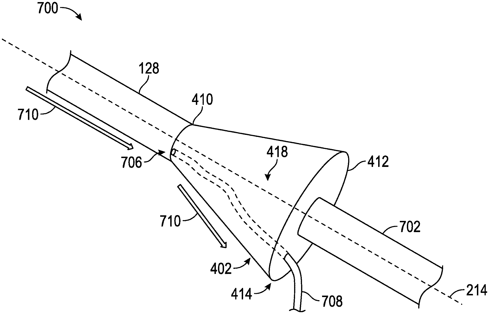
FIG. 7 is an elevation, partial perspective view of an endoscopic system according to certain embodiments of the present disclosure.
FIG. 8 illustrates a method of performing a surgical procedure according to certain embodiments of the present disclosure.
DEFINITIONS
Certain terms are used throughout the following description and claims to refer to particular system components. As one skilled in the art will appreciate, different companies may refer to a component by different names. This document does not intend to distinguish between components that differ in name but not function. In the following discussion and in the claims, the terms "including" and "comprising" are used in an open-ended fashion, and thus should be interpreted to mean "including, but not limited to . . . ." Also, the term "couple" or "couples" is intended to mean either an indirect or direct connection. Thus, if a first device couples to a second device, that connection may be through a direct connection or through an indirect electrical connection via other devices and connections.
"Endoscopic device" shall mean an endoscope alone, a sheath alone, or a combination device comprising an endoscope telescoped within a sheath.
"Above," in relation to a fluid bag (e.g., saline bag) and a component, shall mean the fluid bag has a higher elevation than the recited component measured with respect to local gravity.
"Drip flange" shall mean a component disposed on an outside surface of an elongate shaft of an endoscopic device where the drip flange defines an outer dimension greater than an outside diameter of the elongate shaft. For at least some orientations of the endoscopic device, the drip flange is configured to force fluid that encounters the drip flange to drip from or stream from the drip flange rather than run past the drip flange and back onto the outside surface of the elongate shaft downstream of the drip flange.
"Removably coupled" shall mean a first component coupled to a second component such that first component can be decoupled from the second component without destroying or rendering the first or second components non-functional.
"Monolithic," with respect to a drip flange, shall mean a drip flange that is formed as an integral part of an endoscopic device.
"Drip edge" shall mean a portion of a drip flange that acts as a drip point for fluid.
DETAILED DESCRIPTION
The following discussion is directed to various embodiments. Although one or more of these embodiments may be preferred, the embodiments disclosed should not be interpreted, or otherwise used, as limiting the scope of the disclosure, including the claims. In addition, one skilled in the art will understand that the following description has broad application, and the discussion of any embodiment is meant only to be exemplary of that embodiment, and not intended to intimate that the scope of the disclosure, including the claims, is limited to that embodiment.
Medical endoscopes are often inserted into cavities filled with patient or surgical fluids. In an operative hysteroscopy, an endoscopic device is inserted into the patient's uterus to view and treat various pathologies. A space in which to navigate is created by injecting fluid at a pressure that causes the uterus to expand. This fluid is often circulated to clear debris during the procedure. Although this endoscopic procedure permits the surgeon to perform the procedure, the procedure creates risk for the patient since fluid may be absorbed into the bloodstream at high pressures and cause life-threatening physiological states. As a result, physicians routinely monitor the difference in the fluid flowing in and out of the patient throughout the procedure. Drapes are used to collect fluid which may be accidentally lost during the procedure to ensure an accurate fluid volume measurement.
As an example, when an endoscopic device is inserted through a patient's cervix, the cervix expands circumferentially to accommodate the scope, effectively creating a seal. Depending on the pressure used, the diameter of the scope, and other factors, the fluid may leak between the scope and the cervix. In hysteroscopy, the scope is often positioned with its distal tip elevated, and the surgeon seated and holding the scope. As a result, leaked fluid often drips down the length of the scope and onto the surgeon, floor, or camera. This fluid leakage may lead to an inability to accurately monitor fluid in and out of the patient, and may interfere with the surgeon's vision if the camera becomes flooded. Further, in cases where leakage is difficult to prevent, drapes, absorbent pads, protective covers, and personal protective equipment are used to keep fluid from the floor, equipment, or operating room staff.
At least in accordance with some embodiments, a drip flange comprising a drip edge is added to an endoscope to arrest or redirect the flow of fluid adhering to the outer surface of the endoscope. The drip flange prevents fluid from reaching tubing, electronics, attached equipment, or other locations where the fluid might negatively impact the patient, user, or procedure. The drip flange may be permanently, removably, or adjustably coupled to the endoscopic device. In some embodiments, the drip flange may be formed as an integral part of an endoscopic device.
In an embodiment, the drip flange defines a conical frustum shape that defines a central axis, a proximal end, and a distal end, wherein an outer diameter of the proximal end is larger than an outer diameter of the endoscopic device. In an alternate embodiment, the drip flange defines a disc shape that defines a central axis, a proximal side, and a distal side, wherein an outer diameter of the proximal end of the drip flange mechanism is larger than an outer diameter of the endoscopic device. The disc-shaped drip flange may comprise a flat distal surface on the distal side relative to a plane perpendicular to the central axis. In alternate embodiments, disc-shaped drip flange may comprise a concave or convex distal surface on the distal side relative to a plane perpendicular to the central axis.
FIG. 1 shows an example endoscopic system 100. In an embodiment, the system 100 comprises an endoscopic device 104 comprising an elongate shaft 128, and a distal tip 116 which is inserted through an aperture 102. In the example, the endoscopic device 104 is connected to a fluid pump 106 and a fluid reservoir 112 (such as a saline bag) by way of a first fluid line 108 that is coupled to a first fluid port 120. In various embodiments, the fluid pump 106 may be fluidly coupled to a separate fluid reservoir 112, and in alternate embodiments the fluid pump 106 may comprise a fluid reservoir. The fluid pump 106 may in some embodiments be a peristaltic pump (as shown), a positive displacement pump, or a centrifugal pump, any of which may be employed to generate fluid inflow. In other embodiments, the fluid pump 106 may be omitted and the fluid reservoir 112 may be in direct fluid communication with the first fluid port 120 and/or a second fluid port 122.
The second fluid port 122 may be in communication with a fluid path such as a fluid outflow path. In the example embodiment, the second fluid line 110 may be coupled to a suction mechanism such as a suction wall pump 118, which may be a stand-alone feature or which may be part of a unit that may include a plurality of other controls for power, display, and adjustment of rate of fluid flow. During an operative procedure, fluid may leak from the aperture 102 along an outside surface of the elongate shaft 128 towards the proximal end 126 of the endoscopic device 104. In an effort to direct this fluid flow away from the proximal end 126, a drip flange may be employed to direct the fluid flow away from the proximal end 126 of the endoscopic device 104. In this example, the fluid flow is directed away from the proximal end 126 such that it does not touch the proximal end 126 of the endoscopic device 104.
In a hysteroscopy procedure, the distal end 124 of endoscopic device 104 is inserted into an aperture 102 that may be a patient's cervix. The patient's cervix 102 may expand circumferentially to accommodate the endoscopic device 104, and effectively create a seal. The drip flange 114 is located on the elongate shaft 128 of the endoscopic device 104, and outside the body of the patient and is not in contact with the patient during the procedure. The drip flange 114 receives and redirects fluid away from the proximal end 126 when the fluid leaks out of the cervix 102 and down the outside surface of the elongate shaft 128.
In alternate embodiments, the drip flange 114 may be permanently coupled to the elongate shaft 128 of the endoscopic device 104 or may be a disposable component. The drip flange 114 may be coupled to the endoscopic device 104 between the proximal end 126 and the distal end 124 but is not in direct contact with the distal end 126. In various embodiments, the drip flange 114 may be (1) formed as an integral part of the endoscopic device 104, (2) removably coupled to the endoscopic device 104, (3) permanently coupled to the endoscopic device 104, and/or (4) adjustable along the elongate sheath 128, or combinations thereof. In one example, the drip flange 114 may be permanently coupled to the endoscopic device 104 in that it cannot be removed without being destroyed or destroying the endoscopic device 104 but where the drip flange 114 is adjustable along a portion of the elongate sheath 128. In another example, the drip flange 114 may be removably coupled to the endoscopic device 104 in and is removed without being destroyed and without destroying the endoscopic device 104.
FIG. 2 is an elevated partial perspective view 200 of a tissue removal system and illustrates a partial view of the endoscopic device 104, and that the distal end 116 is inserted through the aperture 102. In an embodiment, the endoscopic device comprises a central axis 214, the distal end 124, the distal tip 116, and the elongate shaft 128. The elongate shaft 128 comprises the central axis 214, the distal tip 116, and a proximal end 216 of the elongate draft 128. The drip flange 114 may be disposed along the elongate shaft 128 at a predetermined distance from the distal tip 116 and is not in contact with nor coupled to the proximal end 216 of the elongate shaft 128. The drip flange 114 is positioned such that, when the endoscopic device is in use, the drip flange 114 does not form a seal with or restrict fluid from exiting the aperture 102.
The drip flange 114 comprises the central axis 214 shared with the endoscopic device 104, an interior surface that may comprise a coupling mechanism (not shown), a distal side 202, a proximal side 208, and a transition surface 212 comprising a smooth transition area extending radially from the proximal side 208 to the distal side 202. In some embodiments, where a distal end diameter is less than a proximal end diameter, the component may be defined by a shape of a sphere, conical frustum, disc, pyramid, polygon, or combinations thereof.
The drip flange 114 may be formed as a monolithic piece with a sheath (not separately shown) of the endoscopic device 104. In an alternate embodiment, the drip flange 114 may be adjustably and/or removably coupled to an elongate shaft 128 of a sheath of the endoscopic device 104. The drip flange 114 may be fabricated as a single piece or as a multiple-component piece comprising drains and/or sponges as discussed in detail herein.
In an example disc drip flange 114 illustrated in FIG. 2, the surfaces corresponding to each of the proximal 208 and distal 202 sides of the drip flange 114 may be flat, converse, or concave, or combinations thereof, where a flat surface is defined as perpendicular with respect to the central axis 214. FIG. 2 further illustrates that the distal tip 124 is located above the proximal end 126, indicated by the arrows since FIG. 2 is a partial view. There is a fluid flow 204 established along an outside surface of the elongate shaft 128 from the distal end 124 towards the distal side 202 of the drip flange 114. The fluid flow 204 exits the endoscopic device 104 at a drip edge 210 of the drip flange, and does not contact the proximal end 216 of the elongate shaft 128, nor the proximal end 126 of the endoscopic device 104.
In an embodiment, when fluid leaks from the aperture 102, it travels along at least a portion of the fluid path 204 along the elongate shaft 128 towards the drip flange 114. In an embodiment, if the distal side 202 comprises a concave surface relative to a plane perpendicular to the central axis 214, the fluid collects in the drip flange 114 on the distal side and may drip along drip edge 210 and/or the transition surface 212. In an embodiment, the fluid drips from a point on the drip flange 114 and can then be captured to monitor fluid volume or disposed of in a receptacle (not shown). In an alternate embodiment, a second drip edge 218 may exist at the boundary of the proximal side 208 of the drip flange 114. The second drip edge 218 may be employed in various embodiments, for example, when the transitional surface 212 is at an angle other than parallel to the central axis 214.
FIGS. 3A and 3B are magnified views of a drip flange 114. FIGS. 3A and 3B illustrate the drip flange 114 in the shape of a disc. The drip flange 114 may comprise the drip edge 210, the distal side 202, the transition surface 212, the proximal side 208, the central axis 214, a through-hole or bore 302 defined by an interior surface 304. In an embodiment, there may be mating features disposed on the interior surface 304 of the bore 302 may permanently or removably couple to the elongate shaft of an endoscopic device. In some embodiments, the position of the drip flange may be adjustable along a length of the elongate shaft. In alternate embodiments, the drip flange may be formed as an integral part of the endoscopic device.
In an embodiment, at least one of the proximal side 208 and the distal side 202 may be defined by surfaces that are perpendicular with respect to the central axis. In alternate embodiments (not shown), the distal side 202 and/or the proximal surface may be concave or convex with respect to a reference line 306 perpendicular to the central axis 214. In various embodiments, the drip flange 114 may be coupled to an endoscopic device 104 when the drip flange 114 is telescoped over the endoscopic device, which may be an endoscope, a sheath, and/or an endoscope telescoped through a sheath.
FIG. 4 is a partial perspective view 400 of an endoscopic system. In particular, FIG. 4 shows a partial view of the endoscopic device 104, and that the distal end 116 is inserted through the aperture 102. In an embodiment, the endoscopic device comprises a central axis 214, the distal end 124, the distal tip 116, and the elongate shaft 128. The elongate shaft 128 comprises the central axis 214, the distal tip 116, and a proximal end 216 of the elongate draft 128, and a drip flange 402 is coupled to the elongate shaft 128.
The drip flange 402 may be formed as a monolithic piece with the endoscopic device 104, or may be a component 402 that is adjustably and/or removably coupled to a length of an elongate shaft 128 of the endoscopic device 104. A drip flange 402 in the shape of a conical frustum is illustrated in FIG. 4. The drip flange 402 comprises the central axis 214 shared with the endoscopic device 104, an interior surface that may comprise a coupling mechanism (not shown), a distal end 410, a proximal end 412, and an outside surface 418 comprising a smooth transition area extending radially from the proximal end 412 to the distal end 410 and that may be referred to as the outside surface 418. In an embodiment, a diameter of the distal end 410 of the drip flange 402 is smaller than a diameter of the proximal end 412.
FIG. 4 further illustrates that the distal tip 124 is located above the proximal end 126, indicated by the arrows since FIG. 4 is a partial view. There is a fluid flow 404 established along an outside surface of the elongate shaft 128 from the distal end 124 towards the distal end 410 of the drip flange 402 along the outside surface 418. The fluid flow 404 exits the endoscopic device 104 at the drip edge 414 of the drip flange 402, and does not contact the proximal end 406 of the elongate shaft 128, nor the proximal end 126 of the endoscopic device 104. The drip flange 402 may be coupled to the elongate shaft 128 between the distal end 116 of the endoscopic device 104 and the proximal end 406 of the elongate shaft 128, and is not in contact with the proximal end 406. In an embodiment, a diameter of the distal end 410 of the drip flange 402 is smaller than a diameter of the proximal end 412.
In FIG. 4, the drip flange 402 is shaped similar a cone, with the distal end 410 positioned at, for example, a 45 degree angle to the elongate shaft 128 and the central axis 214. The drip flange 402 may be coupled to endoscopic device 104 either permanently or removably, and may be reusable or disposable. As fluid leaks out of the aperture 102 and travels along the elongate shaft 128 of the endoscopic device 104, the fluid is redirected to travel down the outside surface 418 of the drip flange 402 and to the drip edge 414. It is appreciated that the drip edge 414 extends circumferentially around the drip flange 402. The fluid can then be captured to monitor fluid volume or disposed of in a receptacle (not shown). The drip flange 402 prevents leaking fluid from reaching the endoscope tubing 110 or attached equipment (not shown) towards the proximal end 126 of the endoscopic device 104. In an alternative embodiment, a sponge or absorbent feature may be added to the drip flange 402 at the distal end 410, along the outside surface 418, and/or at the drip edge 414 to capture the leaking fluid.
FIG. 5 is a partial perspective view 500 of an endoscopic system and illustrates a partial view of the endoscopic device 104, and that the distal end 116 is inserted through the aperture 102. In an embodiment, the endoscopic device 104 comprises a central axis 214, the distal end 124, the distal tip 116, and the elongate shaft 128. The elongate shaft 128 comprises the central axis 214, the distal tip 116, and a proximal end 216 of the elongate draft 128, and a drip flange 502 is coupled to the elongate shaft 128.
The drip flange 502 may be formed as a monolithic piece with the endoscopic device 104, or may be a component 502 that is adjustably and/or removably coupled to the elongate shaft 128 of a sheath of the endoscopic device 104. A drip flange 502 in the shape of a conical frustum is illustrated in FIG. 5. The drip flange 502 comprises the central axis 214 shared with the endoscopic device 104, an interior surface that may comprise a coupling mechanism (not shown), a distal end 506, a proximal end 510, and an outside surface 508 extending radially from the proximal end 510 to the distal end 506. In an embodiment, a diameter of the distal end 506 of the drip flange 502 is larger than a diameter of the proximal end 510.
FIG. 5 further illustrates that the distal tip 124 is located above the proximal end 126, the direction of which is indicated by the arrows since FIG. 5 is a partial view. There is a fluid flow 504 established along an outside surface of the elongate shaft 128 from the distal end 124 along the distal end 506 of the drip flange 502. The fluid flow 504 exits the endoscopic device 104 at the drip edge 512 of the drip flange 502, and the fluid does not contact the proximal end 510 of the elongate shaft 128. In an embodiment, the drip flange 502 does not contact the proximal end 126 of the endoscopic device 104. It is appreciated that the drip edge 512 extends circumferentially around the drip flange 502.
As illustrated by the fluid path 504, as fluid leaks out of the aperture 102 and travels along the outside surface of the elongate shaft 128, the fluid is redirected to travel down the distal end 506 of the drip flange 502 and to the drip edge 512. In some embodiments, the fluid can then be captured to monitor fluid volume or disposed of in a receptacle (not shown). The drip flange 502 prevents fluid from reaching the endoscope tubing 110 or attached equipment (not shown) towards the proximal end 126 of the endoscopic device 104. In an alternative embodiment, a sponge or other absorbent feature may be added to the drip flange 502 at the distal end 506 and/or at the drip edge 512 to capture the leaking fluid.
FIG. 6A is a cross-sectional view 600A of a conical frustum version of a drip flange. The drip flange 402 in FIG. 6A may be similar to that in FIG. 4. FIG. 6A illustrates the drip flange 402, the central axis 214, a channel 602 extending from the proximal end 412 to the distal end 410, and an interior surface 604 of the channel 602. An interior diameter 606 of the channel 602 may be the same as the diameter of the distal end 410, and an outer diameter 608 of the proximal end 412 is larger than the diameter of the distal end 410. In some embodiments, the interior surface of the channel 602 may comprise mating/coupling features (not pictured) configured to mate with an endoscopic device. In various embodiments, the drip flange 402 may be coupled to an endoscopic device when the drip flange 402 is telescoped over the endoscopic device, which may be in the form of an endoscope, a sheath, and/or an endoscope telescoped through a sheath.
FIG. 6B is a magnified perspective view 600B of a drip flange in the shape of a conical frustum. The drip flange 402 in FIG. 6B may be similar to that in FIG. 4. FIG. 6B illustrates the drip flange 402, and illustrates the channel 602 that extends through the solid body of the drip flange 402. In various embodiments, the drip flange 402 may be coupled to an endoscopic device when the drip flange 402 is telescoped over the endoscopic device, which may be in the form of an endoscope, a sheath, and/or an endoscope telescoped through a sheath. It is appreciated that the discussion above with respect to the solid body and the coupling of the drip flange 402 may also be applied to the drip flange 502 discussed above.
FIG. 7 is a partial perspective view of an endoscopic system 700. FIG. 7 illustrates a system 700 coupled to a tubing 708 that comprises a distal end 702 that captures, through pressure or otherwise, the fluid leaking (illustrated by fluid flow 710) from the patient and traveling down elongate shaft 128. The tubing 708 comprises a flexible, rigid, or semi-rigid structure that extends through the drip flange 402 from the distal side 410 through to the proximal end 412. The tubing 708 can be attached to either the elongate shaft 128 and/or the drip flange 402 and/or the drip edge. Once the fluid enters the tubing 708 at the distal side 410 at 706, the fluid can be directed to a receptacle (not shown) in order to monitor fluid flow or it can be disposed of as waste. In an alternative embodiment, a sponge or absorbent feature may be added to the drip flange 402 to capture any leaking fluid that does not travel into the tubing 708.
FIG. 8 illustrates a method 800 of performing a surgical procedure. At block 802, an endoscopic device is assembled. The endoscopic device may be assembled by (1) telescoping an endoscope into a sheath to form the endoscopic device and then telescoping a drip flange over the endoscopic device; (2) telescoping an endoscope into a sheath with a drip flange formed monolithically with the sheath; (3) telescoping the endoscope through the sheath, when the drip flange is one of permanently or removably coupled to the sheath prior to telescoping the endoscope; (4) telescoping the drip flange over the sheath; or (5) telescoping the drip flange over an endoscope.
At block 804, a distal tip of an endoscopic device is positioned to abut an aperture into an operative cavity, the endoscopic device comprises a central axis, a proximal end, a distal end, a distal tip, and an elongate shaft extending from the distal tip towards the proximal end. At block 806, the distal tip of the endoscopic device is inserted through the aperture and fluid flow is initiated and/or established through the endoscopic device at block 808 for a surgical procedure. At block 810, fluid flowing from the aperture is directed from the distal end of the endoscopic device along the elongate shaft and towards the drip flange and the drip edge of the drip flange. At block 812, the distal tip is removed through the aperture and fluid flow is terminated at block 814.
In some embodiments, the drip flange may be removed from the endoscopic device (uncoupled) at block 816 without compromising the functionality of the endoscopic device, and, may be either disposed of at block 818 or cleaned/sterilized/reused at block 820, at which point the method 800 may return to block 802 where the endoscopic device is re-assembled.
The above discussion is meant to be illustrative of the principles and various embodiments of the present invention. Numerous variations and modifications will become apparent to those skilled in the art once the above disclosure is fully appreciated. For example, various combinations of perforations types, number, geometry, and size may be employed in different embodiments and may be employed along varying lengths of the endoscopic device. It is intended that the following claims be interpreted to embrace all such variations and modifications.
* * * * *
D00000
D00001
D00002
D00003
D00004
D00005
D00006
D00007
D00008
XML
uspto.report is an independent third-party trademark research tool that is not affiliated, endorsed, or sponsored by the United States Patent and Trademark Office (USPTO) or any other governmental organization. The information provided by uspto.report is based on publicly available data at the time of writing and is intended for informational purposes only.
While we strive to provide accurate and up-to-date information, we do not guarantee the accuracy, completeness, reliability, or suitability of the information displayed on this site. The use of this site is at your own risk. Any reliance you place on such information is therefore strictly at your own risk.
All official trademark data, including owner information, should be verified by visiting the official USPTO website at www.uspto.gov. This site is not intended to replace professional legal advice and should not be used as a substitute for consulting with a legal professional who is knowledgeable about trademark law.