Combinative shelving unit
Chen November 24, 2
U.S. patent number 10,842,263 [Application Number 16/728,524] was granted by the patent office on 2020-11-24 for combinative shelving unit. The grantee listed for this patent is Tong-Fu Chen. Invention is credited to Tong-Fu Chen.


View All Diagrams
| United States Patent | 10,842,263 |
| Chen | November 24, 2020 |
Combinative shelving unit
Abstract
A combinative shelving unit includes two stand assemblies and a load tray. The two stand assemblies are arranged parallel to each other. Each stand assembly includes a pair of posts and a transverse link connected between the pair of posts. Each transverse link has a first assembling portion and a second assembling portion. One side of the load tray has a connecting portion and another side thereof has a second connecting portion. The first connecting portion and the second connecting portion are staggered in position. The first connecting portion engages with the first assembling portion of one of the transverse links, and the second connecting portion engages with the second assembling portion of another one of the transverse links.
| Inventors: | Chen; Tong-Fu (Taipei, TW) | ||||||||||
|---|---|---|---|---|---|---|---|---|---|---|---|
| Applicant: |
|
||||||||||
| Family ID: | 1000004574425 | ||||||||||
| Appl. No.: | 16/728,524 | ||||||||||
| Filed: | December 27, 2019 |
| Current U.S. Class: | 1/1 |
| Current CPC Class: | A47B 47/0091 (20130101); A47B 55/02 (20130101); A47B 47/0083 (20130101); A47B 45/00 (20130101); A47B 47/00 (20130101); A47B 57/06 (20130101); A47F 5/01 (20130101); B65D 1/38 (20130101); A47B 57/00 (20130101) |
| Current International Class: | A47B 47/00 (20060101); A47B 55/02 (20060101); A47B 45/00 (20060101); A47F 5/01 (20060101); A47B 57/06 (20060101); A47B 57/00 (20060101); B65D 1/38 (20060101) |
| Field of Search: | ;211/181.1,187 |
References Cited [Referenced By]
U.S. Patent Documents
| 2315595 | April 1943 | Chappory |
| D165118 | November 1951 | Strinning |
| D180883 | August 1957 | Perry |
| 2903137 | September 1959 | Brown |
| 3097615 | July 1963 | Ross |
| 3200959 | August 1965 | Theim |
| 3208408 | September 1965 | Maslow |
| 3232442 | February 1966 | Wilson |
| 3252434 | May 1966 | Young, Jr. |
| 3280989 | October 1966 | Melvin |
| 3316864 | May 1967 | Maslow |
| D209490 | December 1967 | Baxter |
| 3589746 | June 1971 | Inglis |
| 3680712 | August 1972 | Jurasek |
| 3884358 | May 1975 | Marschak |
| 3915097 | October 1975 | Young, Jr. |
| 3977529 | August 1976 | Stroh |
| 4191160 | March 1980 | Elliott |
| 4313544 | February 1982 | Ashton |
| 4915462 | April 1990 | Le Marchand |
| 5065873 | November 1991 | Tseng |
| 5221014 | June 1993 | Welch |
| 5251973 | October 1993 | Hazan |
| 5326062 | July 1994 | Remmers |
| 5718441 | February 1998 | Kern |
| D405627 | February 1999 | Salvucci |
| 5913270 | June 1999 | Price |
| 6079575 | June 2000 | Wang |
| 6095347 | August 2000 | Mauro-Vetter |
| 6135299 | October 2000 | Burgess |
| 6318570 | November 2001 | Mueller |
| D584906 | January 2009 | Vanderheyden |
| 7533948 | May 2009 | Smith |
| 7857329 | December 2010 | Cai |
| 7967157 | June 2011 | Bilotto |
| 8025163 | September 2011 | McAllister |
| 8196761 | June 2012 | Morandi |
| 8267261 | September 2012 | Vanderhoek |
| 8505933 | August 2013 | Bernard |
| 8640893 | February 2014 | Kessell |
| 8739986 | June 2014 | Preidt |
| 9004300 | April 2015 | Morrell |
| D746089 | December 2015 | Hsu |
| 9247834 | February 2016 | Lucht |
| 9987876 | June 2018 | Tuang |
| 10561297 | February 2020 | Maslana |
| 2002/0130098 | September 2002 | Simard |
| 2006/0032829 | February 2006 | Hutzler |
| 2006/0157435 | July 2006 | Oberhaus |
| 2007/0034584 | February 2007 | Park |
| 2007/0210025 | September 2007 | Oberhaus |
| 2009/0152225 | June 2009 | Lee |
| 2010/0288717 | November 2010 | Morandi |
| 2011/0233164 | September 2011 | Chang |
| 2019/0133413 | May 2019 | Maslana |
| 2020/0214443 | July 2020 | Cheng |
Assistant Examiner: Barnett; Devin K
Attorney, Agent or Firm: Shih; Chun-Ming HDLS IPR Services
Claims
What is claimed is:
1. A combinative shelving unit comprising: two stand assemblies, arranged parallel to each other, each comprising a pair of posts and a transverse link connected between the pair of posts, and each transverse link having a first assembling portion and a pair of second assembling portions, each first assembling portion is a first inverted-U section which is bent upward from each transverse link respectively, and the second assembling portions of each transverse link are a pair of second inverted-U sections which are bent upward from each transverse link respectively; at least one load tray comprising a front, a rear, a first side and a second side opposite the first side, a first protrusion protruding outwardly from the first side and a pair of spaced apart second protrusions protruding outwardly from the second side, the first protrusion being staggered and offset from the second protrusions, the first protrusion is configured to receive the first assembling portion of a first corresponding transverse link therein, and the second protrusions are configured to receive the second assembling portions of a second corresponding transverse link therein.
2. The combinative shelving unit of claim 1, wherein two opposite sides of the first protrusion section of the at least one load tray is formed with a first recess section for receiving one of the second assembling portions of the first corresponding transverse link, and wherein a second recess section is formed between the pair of second protrusions of the at least one load tray for receiving the first assembling portion of the second corresponding transverse link.
3. The combinative shelving unit of claim 2, wherein each stand assembly comprises a U-shaped rod, and each pair of posts is separately formed at two ends of each U-shaped rod respectively.
4. The combinative shelving unit of claim 1, further comprising a basket, which is fastened on the at least one load tray by welding or screwing.
5. The combinative shelving unit of claim 4, wherein the basket has an annular frame disposed on the at least one load tray, and the annular frame abuts against the two pairs of posts.
6. The combinative shelving unit of claim 5, wherein the annular frame is bent to form four indents, which abut against each pair of posts respectively.
7. The combinative shelving unit of claim 1, further comprising a box, and the at least one load tray is fixed under the box.
8. The combinative shelving unit of claim 1, further comprising a third stand assembly, wherein the two stand assemblies and the third stand assembly are three stand assemblies, the three stand assemblies are parallel and horizontally spaced apart, the at least one load tray is at least two load trays, the first protrusion of a first corresponding tray of the at least two load trays is embedded into the first inverted-U section of the first corresponding transverse link which is located at an intermediate position and the second protrusions of the first corresponding tray are separately embedded into the second inverted-U sections of the second corresponding transverse link, the two second protrusion sections of a second corresponding load tray of the at least two load trays are separately embedded into the two second inverted-U sections of a third corresponding transverse link, and the first protrusion of the second corresponding load tray is embedded into the first inverted-U section of the second corresponding transverse link.
9. The combinative shelving unit of claim 1, wherein the two stand assemblies are upper stand assemblies and each pair of posts are upper pairs of posts, wherein two lower stand assemblies each comprising a lower pair of posts are are detachably connected to a bottom end of the upper pair of posts respectively.
10. The combinative shelving unit of claim 9, wherein each bottom ends of the upper posts is a sleeve, wherein top ends of the lower posts comprise insert tubes, and each sleeve is detachably connected with one of the insert tubes.
11. The combinative shelving unit of claim 1, wherein the at least one load tray comprises a plurality of load trays.
Description
BACKGROUND OF THE INVENTION
Technical Field
The invention relates to a shelving unit with cost-saving, modularized expansion and easy assembly, particularly to a combinative shelving unit.
Related Art
Shelving storage units are popularly used in houses, stores and warehouses for storing items. With the trend of modern decoration design tending towards personalization and customization, it becomes more necessary for shelves to have expansibility and variability in design.
However, current self-assembling shelving units in the market usually require bolts and/or screws for fixtures. This makes both assembling and disassembling the shelving units time consuming and laborious. As a result, users always feel that the experience is inconvenient and inefficient. In addition, when the number of conventional shelving units needs to be changed, the shelves can only be altered vertically, and any horizontal expansion or reduction is unavailable. This causes poor variability in customization.
SUMMARY OF THE INVENTION
An object of the invention is to provide a combinative shelving unit, which has features of tool-free, cost-saving, modularized expansion and easy assembly.
To accomplish the above object, the combinative shelving unit of the invention includes two stand assemblies and a load tray. The two stand assemblies are arranged parallel to each other. Each stand assembly includes a pair of posts and a transverse link connected between the pair of posts. Each transverse link has a first assembling portion and a second assembling portion. One side of the load tray has a connecting portion and another side thereof has a second connecting portion. The first connecting portion and the second connecting portion are staggered in position. The first connecting portion engages with the first assembling portion of one of the transverse links, and the second connecting portion engages with the second assembling portion of another one of the transverse links.
Accordingly, four stand assemblies can be vertically assembled to adjust the overall height of the combinative shelving unit. This can improve expansibility and variability of a combinative shelving unit.
Accordingly, three stand assemblies can be horizontally assembled to adjust the overall width of the combinative shelving unit. This can improve the expansibility and variability of a combinative shelving unit and its structural strength and save the number of components required.
BRIEF DESCRIPTION OF THE DRAWINGS
FIG. 1 is a partially exploded view of the first embodiment of the invention;
FIG. 2 is a partially cross-sectional and exploded view of the first embodiment of the invention;
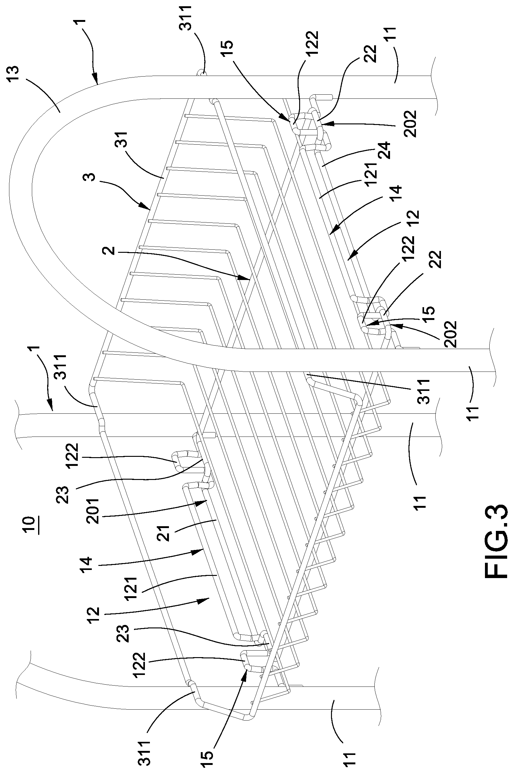
FIG. 3 is a partially perspective assembled view of the first embodiment of the invention;
FIG. 4 is a cross-sectional assembled view of the first embodiment of the invention;
FIG. 5 is a perspective assembled view of the first embodiment of the invention;
FIG. 6 is a perspective exploded view of the second embodiment of the invention;
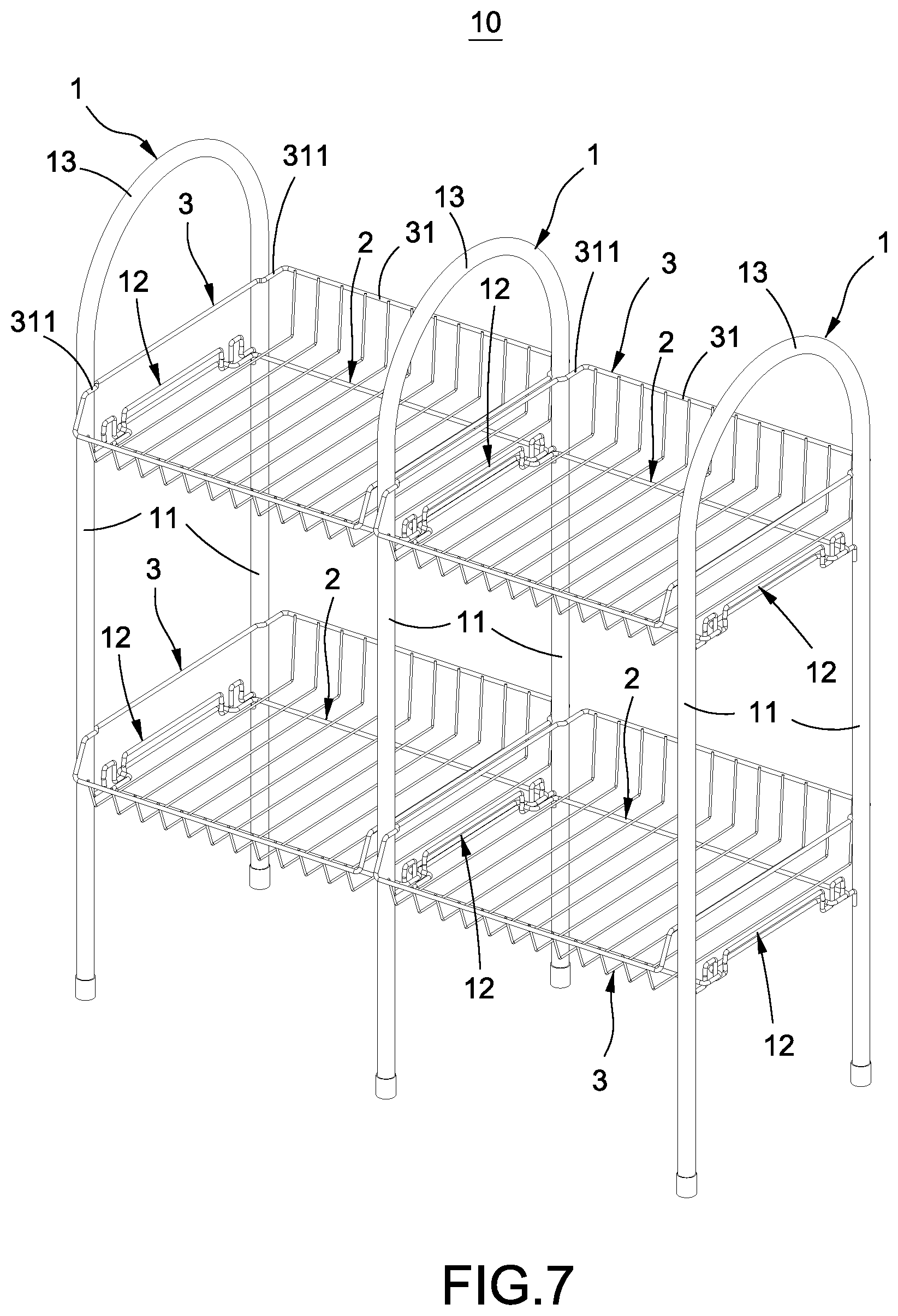
FIG. 7 is a perspective assembled view of the third embodiment of the invention;
FIG. 8 is a cross-sectional assembled view of the third embodiment of the invention;
FIG. 9 is a partially exploded view of the fourth embodiment of the invention;
FIG. 10 is a perspective assembled view of the fourth embodiment of the invention; and
FIG. 11 is a partially enlarged view of the fourth embodiment of the invention.
DETAILED DESCRIPTION OF THE INVENTION
Please refer to FIGS. 1-5. The invention provides the first embodiment of a combinative shelving unit. The combinative shelving unit 10 includes two or more stand assemblies 1 and one or more load trays 2.
As shown in FIGS. 1-5, the number of the stand assemblies 1 is two. The two stand assemblies 1 are arranged to be parallel to each other. Each stand assembly 1 includes a pair of posts 11 and one or more transverse links 12 connected between the pair of posts 11. Each transverse link 12 has one or more first assembling portions 14 and one or more second assembling portions 15.
In detail, in this embodiment, the number of the first assembling portion 14 is one and the number of the second assembling portions 15 is two. The two assembling portions 15 are arranged at two opposite ends of the first assembling portion 14. The first assembling portion 14 is a first inverted-U section 121 which is bent upward from the transverse link 12. The two second assembling portions 15 are two inverted-U sections 122 which are bent upward from the transverse link 12.
In addition, each stand assembly 1 includes a U-shaped rod 13, and each pair of posts 11 is separately formed at two ends of the U-shaped rod 13. In this embodiment, two ends of each transverse link 12 are fixed to two ends of one of the pairs of posts 11 by welding, but are not limited to this. Two ends of each transverse link 12 are fixed to two ends of one of the pairs of posts 11 by welding, telescopically connecting them or connecting them in another manner.
As shown in FIGS. 1-5, one side of the load tray 2 has one or more connecting portions 201 and another side thereof has one or more second connecting portions 202. The first connecting portion 201 and the second connecting portion 202 are staggered in position. The first connecting portion 201 engages with the first assembling portion 14 of one of the transverse links 12. The second connecting portion 202 engages with the second assembling portion 15 of another one of the transverse links 202.
In detail, in this embodiment, the number of the first connecting portion 201 is one and the number of the second connecting portions 201 is two. The first connecting portion 201 is a first protrusion section 21 bent outward from the load tray 2. The two second connecting portions 202 are two second protrusion sections 22 bent outward from the load tray 2. The first protrusion section 21 engages with the first inverted-U section 121 of one of the transverse links 12. The two second protrusion sections 22 separately engage with the two second inverted-U sections 122 of another one of the transverse links 12.
In addition, each of two opposite sides of the first protrusion section 21 of the load tray 2 is formed with a first recess section 23 for receiving one of the second protrusion sections 22, and a second recess section 24 for receiving the first protrusion section 21 is formed between the two second protrusion sections 22 of the load tray 2.
In this embodiment, the load tray 2 is multiple in number. Multiple load trays 2 are vertically arranged and the number of multiple load trays 2 may be changed.
As shown in FIGS. 1-3 and 5, the combinative shelving unit 10 of the invention further includes one or more baskets 3, which are the same as the load trays 2 in number. Each basket 3 is fastened on the load tray 2 by welding or screwing.
In detail, the basket 3 has an annular frame 31 disposed on the load tray 2. A height difference s is formed between the annular frame and the load tray 2. The annular frame 31 is bent to form four indents 311, which separately abut against the two pairs of posts 11 so as to make the annular frame tightly disposed between the two pairs of posts 11. The height difference s exists between the annular frame 31 and the load tray 2 and the annular frame 31 abuts against the two pairs of posts 11, so the basket 3 is fastened between the two pairs of posts 11 in a three-dimensional manner and structural strength of the basket 3 can be stiffened to prevent the basket 3 from tilting. Also, the annular frame 31 is bent to form four indents 311 and the four indents 311 separately abut against the two pairs of posts 11 to further enhance the structural strength of the basket 3.
As shown in FIGS. 3-5, when using the combinative shelving unit 10 of the invention, parallelly arrange two stand assemblies 1 first, and then engage a first protrusion section 21 at a side of the load tray 2 with the first inverted-U section 121 of one of the transverse links 12 and engage two second protrusion sections 22 at another side with two second inverted-U sections 122 of another one of the transverse links 12 to finish assembly of the combinative shelving unit 10. Thereby, the combinative shelving unit 10 of the invention does not require screwing for fixture, and saves time and labor so as to accomplish the advantages of cost-saving, modularized expansion and easy assembly. Please refer to FIG. 6, which shows the second embodiment of the combinative shelving unit 10 of the invention. The second embodiment is approximately identical to the first embodiment. The second embodiment differs from the first embodiment by the number of the stand assemblies 1 being four.
In detail, the stand assemblies 1 are four in number. The four stand assemblies 1 are arranged to be upper, lower, left and right. Each of bottom ends of upper four posts 11 is provided with a sleeve tube 111. Each of top ends of lower four posts 11 is provided with an insert tube 112. Each sleeve tube 111 is detachably connected with one of the insert tubes 112 so as to make the upper pair of posts 11 detachably connected on the lower pair of posts 11. Thereby, the four stand assemblies 1 can be vertically connected to adjust the overall height of the combinative shelving unit 10 and increase expansibility and variability of the combinative shelving unit 10.
Please refer to FIGS. 7-8, which shows the third embodiment of the combinative shelving unit 10 of the invention. The third embodiment is approximately identical to the first embodiment. The third embodiment differs from the first embodiment by the number of the stand assemblies 1 being three.
In detail, the three stand assemblies 1 are arranged to be left and right. The number of the load tray 2 is two or more. The first protrusion section 21 of one of the load trays 2 is embedded into the first inverted-U section 121 of the transverse link 12 which is located at an intermediate position and the two second protrusion sections 22 are separately embedded into the two second inverted-U sections 122 on an outer side. The two second protrusion sections 22 of another load tray 2 are separately embedded into the two second inverted-U sections 122 of the transverse link 12 which is located at an intermediate position, and the first protrusion section 21 is embedded into the first inverted-U section 121 which is located on the other side. Thereby, the three stand assemblies 1 can be horizontally connected to adjust the overall width of the combinative shelving unit 10, and increase the expansibility and variability of the combinative shelving unit 10.
Additionally, conventional shelving units are horizontally expanded only by parallelly placing multiple shelving units. In comparison with conventional shelving, multiple stand assemblies 1 of the invention can be horizontally connected to each other through the load tray 2 to make the combinative shelving unit 10 with enlarged width acquire reinforced structural strength and less components.
Further, the first protrusion section 21 and the two second protrusion sections 22 are staggered in position. Each load tray 2 is provided with two first recess sections 23 at two sides of the first protrusion section 21 for being embedded by the two second protrusion sections 22. Each load tray 2 is provided with one second recess section 24 between the two second protrusion sections 22 for being embedded by the first protrusion section 21. Thereby, when two adjacent load trays 2 are arranged left and right, two second protrusion sections 22 of one of the load trays 2 can be embedded in two first recess sections 23 of another load tray 2, and the first protrusion section 21 of one of the load trays 2 can be embedded in the second recess section 24 of another load tray 2. This makes prevents the assembly of each of the load trays 2 from interfering with each other and affecting their appearance.
Please refer to FIGS. 9-11, which shows the fourth embodiment of the combinative shelving unit 10 of the invention. The fourth embodiment is approximately identical to the first embodiment. The fourth embodiment differs from the first embodiment by further including one or more boxes 4. The sum of the numbers of the baskets 3 and boxes 4 is the same as the number of the load trays 2. Each load tray 2 is fixed under the basket 3 or the box 4 by welding or screwing. Thereby, a user can adjust the number or arrangement of the baskets 3 and the boxes 4 to increase the convenience of the combinative shelving unit 10.
The basket 3 is a container without a cover, which is made of interwoven metal wires. The box 4 is a container with a cover, which is formed by plates.
It will be appreciated by persons skilled in the art that the above embodiments have been described by way of example only and not in any limitative sense, and that various alterations and modifications are possible without departure from the scope of the invention as defined by the appended claims.
* * * * *
D00000
D00001
D00002
D00003
D00004
D00005
D00006
D00007
D00008
D00009
D00010
D00011
XML
uspto.report is an independent third-party trademark research tool that is not affiliated, endorsed, or sponsored by the United States Patent and Trademark Office (USPTO) or any other governmental organization. The information provided by uspto.report is based on publicly available data at the time of writing and is intended for informational purposes only.
While we strive to provide accurate and up-to-date information, we do not guarantee the accuracy, completeness, reliability, or suitability of the information displayed on this site. The use of this site is at your own risk. Any reliance you place on such information is therefore strictly at your own risk.
All official trademark data, including owner information, should be verified by visiting the official USPTO website at www.uspto.gov. This site is not intended to replace professional legal advice and should not be used as a substitute for consulting with a legal professional who is knowledgeable about trademark law.