Change-out system for submerged combustion melting burner
Baker , et al. November 17, 2
U.S. patent number 10,837,705 [Application Number 14/855,483] was granted by the patent office on 2020-11-17 for change-out system for submerged combustion melting burner. This patent grant is currently assigned to Johns Manville. The grantee listed for this patent is JOHNS MANVILLE. Invention is credited to John Wayne Baker, Aaron Morgan Huber.


| United States Patent | 10,837,705 |
| Baker , et al. | November 17, 2020 |
Change-out system for submerged combustion melting burner
Abstract
Liquid is delivered into a void between a burner and a melt vessel, which causes a skull of a material to form within an interior of the melt vessel. The void is in fluidic communication with the interior of the melt vessel. The burner is moved from a first position internal to the void to a second position external from the void. Thereafter, the burner is isolated from the void.
| Inventors: | Baker; John Wayne (Golden, CO), Huber; Aaron Morgan (Castle Rock, CO) | ||||||||||
|---|---|---|---|---|---|---|---|---|---|---|---|
| Applicant: |
|
||||||||||
| Assignee: | Johns Manville (Denver,
CO) |
||||||||||
| Family ID: | 58257187 | ||||||||||
| Appl. No.: | 14/855,483 | ||||||||||
| Filed: | September 16, 2015 |
Prior Publication Data
| Document Identifier | Publication Date | |
|---|---|---|
| US 20170074590 A1 | Mar 16, 2017 | |
| Current U.S. Class: | 1/1 |
| Current CPC Class: | C03B 5/2356 (20130101); F27D 99/00 (20130101) |
| Current International Class: | F27D 99/00 (20100101); C03B 5/235 (20060101) |
| Field of Search: | ;432/3,135 ;65/134.5 |
References Cited [Referenced By]
U.S. Patent Documents
| 1579353 | April 1926 | Good |
| 1636151 | July 1927 | Schofield |
| 1679295 | July 1928 | Dodge |
| 1706857 | March 1929 | Mathe |
| 1716433 | June 1929 | Ellis |
| 1675474 | September 1932 | McKinley |
| 1883023 | October 1932 | Slick |
| 1937321 | November 1933 | Howard |
| 1944855 | January 1934 | Wadman |
| 1989103 | January 1935 | McKelvey et al. |
| 2042560 | June 1936 | Stewart |
| 2064546 | December 1936 | Kutchka |
| 2174533 | October 1939 | See et al. |
| 2118479 | January 1940 | McCaskey |
| 2269459 | January 1942 | Kleist |
| 2432942 | December 1947 | See et al. |
| 2455907 | January 1948 | Sayler |
| 2658094 | November 1953 | Nonken |
| 2677003 | April 1954 | Arbeit et al. |
| 2679749 | June 1954 | Poole |
| 2691689 | October 1954 | Arbeit et al. |
| 2718096 | September 1955 | Henry et al. |
| 2773545 | December 1956 | Petersen |
| 2781756 | February 1957 | Kobe |
| 2867972 | January 1959 | Holderreed et al. |
| 2878644 | March 1959 | Fenn |
| 2690166 | June 1959 | Heinze |
| 2902029 | September 1959 | Hill |
| 2981250 | April 1961 | Stewart |
| 3020165 | February 1962 | Davis |
| 3056283 | October 1962 | Tiede |
| 3073683 | January 1963 | Switzer et al. |
| 3084392 | April 1963 | Labino |
| 3088812 | May 1963 | Bitterlich et al. |
| 3104947 | September 1963 | Switzer et al. |
| 3129087 | April 1964 | Hagy |
| 3160578 | December 1964 | Saxton et al. |
| 3165452 | January 1965 | Williams |
| 3170781 | February 1965 | Keefer |
| 3174820 | March 1965 | See et al. |
| 3215189 | November 1965 | Bauer |
| 3224855 | December 1965 | Plumat |
| 3226220 | December 1965 | Plumat |
| 3237929 | March 1966 | Plumat et al. |
| 3239325 | March 1966 | Roberson et al. |
| 3241548 | March 1966 | See et al. |
| 3245769 | April 1966 | Eck et al. |
| 3248205 | April 1966 | Dolf et al. |
| 3248206 | April 1966 | Apple et al. |
| 3260587 | July 1966 | Dolf et al. |
| 3268313 | August 1966 | Burgrnan et al. |
| 3285834 | November 1966 | Guerrieri et al. |
| 3294512 | December 1966 | Penberthy |
| 3325298 | June 1967 | Brown |
| 3375095 | March 1968 | Poole |
| 3380463 | April 1968 | Trethewey |
| 3385686 | May 1968 | Plurnat et al. |
| 3402025 | September 1968 | Garrett et al. |
| 3407805 | October 1968 | Bougard |
| 3407862 | October 1968 | Mustian, Jr. |
| 3420510 | January 1969 | Griem |
| 3421873 | January 1969 | Burgman et al. |
| 3421876 | January 1969 | Schmidt |
| 3432399 | March 1969 | Schutt |
| 3442633 | May 1969 | Perry |
| 3445214 | May 1969 | Oremesher |
| 3498779 | March 1970 | Hathaway |
| 3510393 | May 1970 | Burgman et al. |
| 3519412 | July 1970 | Olink |
| 3525674 | August 1970 | Barnebey |
| 3533770 | October 1970 | Adler et al. |
| 3547611 | December 1970 | Williams |
| 3563683 | February 1971 | Hess |
| 3573016 | March 1971 | Rees |
| 3592151 | July 1971 | Webber |
| 3592623 | July 1971 | Shepherd |
| 3600149 | August 1971 | Chen et al. |
| 3606825 | September 1971 | Johnson |
| 3617234 | November 1971 | Hawkins et al. |
| 3627504 | December 1971 | Johnson et al. |
| 3632335 | January 1972 | Worner |
| 3692017 | September 1972 | Glachant et al. |
| 3717139 | February 1973 | Guillet et al. |
| 3738792 | June 1973 | Feng |
| 3741656 | June 1973 | Shapiro |
| 3741742 | June 1973 | Jennings |
| 3746527 | July 1973 | Knavish et al. |
| 3747588 | July 1973 | Malmin |
| 3754879 | August 1973 | Phaneuf |
| 3756800 | September 1973 | Phaneuf |
| 3763915 | October 1973 | Perry et al. |
| 3764287 | October 1973 | Brocious |
| 3771988 | November 1973 | Starr |
| 3788832 | January 1974 | Nesbitt |
| 3818893 | June 1974 | Kataoka et al. |
| 3835909 | September 1974 | Douglas et al. |
| 3840002 | October 1974 | Douglas et al. |
| 3856496 | December 1974 | Nesbitt et al. |
| 3885945 | May 1975 | Rees et al. |
| 3907565 | September 1975 | Francel et al. |
| 3913560 | October 1975 | Lazarre et al. |
| 3929445 | December 1975 | Zippe |
| 3936290 | February 1976 | Cerutti et al. |
| 3951635 | April 1976 | Rough |
| 3976464 | August 1976 | Wardlaw |
| 4001001 | January 1977 | Knavish et al. |
| 4004903 | January 1977 | Daman et al. |
| 4028083 | June 1977 | Patznick et al. |
| 4083711 | April 1978 | Jensen |
| 4101304 | July 1978 | Marchand |
| 4110098 | August 1978 | Mattmulier |
| 4153438 | May 1979 | Stream |
| 4185982 | January 1980 | Schwenninger |
| 4203761 | May 1980 | Rose |
| 4205966 | June 1980 | Horikawa |
| 4208201 | June 1980 | Rueck |
| 4226564 | October 1980 | Takahashi et al. |
| 4238226 | December 1980 | Sanzenbacher et al. |
| 4249927 | February 1981 | Fakuzaki et al. |
| 4270740 | June 1981 | Sanzenbacher et al. |
| 4282023 | August 1981 | Hammel et al. |
| 4303435 | December 1981 | Sleighter |
| 4309204 | January 1982 | Brooks |
| 4316734 | February 1982 | Spinosa et al. |
| 4323718 | April 1982 | Buhring et al. |
| 4349376 | September 1982 | Dunn et al. |
| 4360373 | November 1982 | Pecoraro |
| 4397692 | August 1983 | Ramge et al. |
| 4398925 | August 1983 | Trinh et al. |
| 4405351 | September 1983 | Sheinkop |
| 4406683 | September 1983 | Demarest, Jr. |
| 4413882 | November 1983 | Bailey et al. |
| 4424071 | January 1984 | Steitz et al. |
| 4432780 | February 1984 | Propster et al. |
| 4455762 | June 1984 | Saeman |
| 4461576 | July 1984 | King |
| 4488537 | December 1984 | Laurent |
| 4508970 | April 1985 | Ackerman |
| 4539034 | September 1985 | Hanneken |
| 4542106 | September 1985 | Sproull |
| 4545800 | October 1985 | Won et al. |
| 4549896 | October 1985 | Streicher et al. |
| 4599100 | July 1986 | Demarest |
| 4622007 | November 1986 | Gitman |
| 4626199 | December 1986 | Bounini |
| 4632687 | December 1986 | Kunkle et al. |
| 4634461 | January 1987 | Dernarest, Jr. et al. |
| 4657586 | April 1987 | Masterson et al. |
| 4718931 | January 1988 | Boettner |
| 4723708 | February 1988 | Berger et al. |
| 4735642 | April 1988 | Jensen |
| 4738938 | April 1988 | Kunkle et al. |
| 4758259 | July 1988 | Jensen |
| 4781576 | November 1988 | Dewitz |
| 4794860 | January 1989 | Welton |
| 4798616 | January 1989 | Knavish et al. |
| 4812372 | March 1989 | Kithany |
| 4814387 | March 1989 | Donat |
| 4816056 | March 1989 | Tsai et al. |
| 4818265 | April 1989 | Krumwiede et al. |
| 4877436 | October 1989 | Sheinkop |
| 4877449 | October 1989 | Khinkis |
| 4878829 | November 1989 | Anderson |
| 4882736 | November 1989 | Pieper |
| 4886539 | December 1989 | Gerutti et al. |
| 4900337 | February 1990 | Zortea et al. |
| 4919700 | April 1990 | Pecoraro et al. |
| 4927866 | May 1990 | Backderf et al. |
| 4932035 | June 1990 | Pieper |
| 4953376 | September 1990 | Merlone |
| 4963731 | October 1990 | King |
| 4969942 | November 1990 | Schwenninger et al. |
| 4973346 | November 1990 | Kobayashi et al. |
| 5011086 | April 1991 | Sonnleitner |
| 5032230 | July 1991 | Shepherd |
| 5052874 | October 1991 | Johanson |
| 5062789 | November 1991 | Gitman |
| 5097802 | March 1992 | Clawson |
| 5168109 | December 1992 | Backderf et al. |
| 5169424 | December 1992 | Grinnen et al. |
| 5194747 | March 1993 | Culpepper et al. |
| 5199866 | April 1993 | Joshi et al. |
| 5204082 | April 1993 | Schendel |
| 5299929 | April 1994 | Yap |
| 5360171 | November 1994 | Yap |
| 5374595 | December 1994 | Dumbaugh et al. |
| 5405082 | April 1995 | Brown et al. |
| 5412882 | May 1995 | Zippe et al. |
| 5449286 | September 1995 | Snyder et al. |
| 5473885 | December 1995 | Hunter, Jr. et al. |
| 5483548 | January 1996 | Coble |
| 5490775 | February 1996 | Joshi et al. |
| 5522721 | June 1996 | Drogue et al. |
| 5545031 | August 1996 | Joshi et al. |
| 5575637 | November 1996 | Slavejkov et al. |
| 5586999 | December 1996 | Kobayashi |
| 5595703 | January 1997 | Swaelens et al. |
| 5606965 | March 1997 | Panz et al. |
| 5613994 | March 1997 | Muniz et al. |
| 5615668 | April 1997 | Panz et al. |
| 5636623 | June 1997 | Panz et al. |
| 5672827 | September 1997 | Jursich |
| 5713668 | February 1998 | Lunghofer et al. |
| 5718741 | February 1998 | Hull et al. |
| 5724901 | March 1998 | Guy et al. |
| 5736476 | April 1998 | Watzke et al. |
| 5743723 | April 1998 | Iatrides et al. |
| 5765964 | June 1998 | Calcote et al. |
| 5814121 | September 1998 | Travis |
| 5829962 | November 1998 | Drasek et al. |
| 5833447 | November 1998 | Bodelin et al. |
| 5849058 | December 1998 | Takeshita et al. |
| 5863195 | January 1999 | Feldermann |
| 5887978 | March 1999 | Lunghofer et al. |
| 5944507 | August 1999 | Feldermann |
| 5944864 | August 1999 | Hull et al. |
| 5954498 | September 1999 | Joshi et al. |
| 5975886 | November 1999 | Phillippe |
| 5979191 | November 1999 | Jian |
| 5984667 | November 1999 | Phillippe et al. |
| 5993203 | November 1999 | Koppang |
| 6029910 | February 2000 | Joshi et al. |
| 6036480 | March 2000 | Hughes et al. |
| 6039787 | March 2000 | Edlinger |
| 6044667 | April 2000 | Chenoweth |
| 6045353 | April 2000 | VonDrasek et al. |
| 6068468 | May 2000 | Phillipe et al. |
| 6071116 | June 2000 | Phillipe et al. |
| 6074197 | June 2000 | Phillippe |
| 6077072 | June 2000 | Marin et al. |
| 6085551 | July 2000 | Pieper et al. |
| 6109062 | August 2000 | Richards |
| 6113389 | September 2000 | Joshi et al. |
| 6116896 | September 2000 | Joshi et al. |
| 6120889 | September 2000 | Turner et al. |
| 6123542 | September 2000 | Joshi et al. |
| 6126438 | October 2000 | Joshi et al. |
| 6154481 | November 2000 | Sorg et al. |
| 6156285 | December 2000 | Adams et al. |
| 6171100 | January 2001 | Joshi et al. |
| 6178777 | January 2001 | Chenoweth |
| 6183848 | February 2001 | Turner et al. |
| 6210151 | April 2001 | Joshi et al. |
| 6210703 | April 2001 | Novich |
| 6237369 | May 2001 | LeBlanc et al. |
| 6241514 | June 2001 | Joshi et al. |
| 6244197 | June 2001 | Coble |
| 6244857 | June 2001 | VonDrasek et al. |
| 6247315 | June 2001 | Marin et al. |
| 6250136 | June 2001 | Igreja |
| 6250916 | June 2001 | Phillipe et al. |
| 6274164 | August 2001 | Novick |
| 6276924 | August 2001 | Joshi et al. |
| 6276928 | August 2001 | Joshi et al. |
| 6293277 | September 2001 | Panz et al. |
| 6314760 | November 2001 | Chenoweth |
| 6314896 | November 2001 | Marin et al. |
| 6332339 | December 2001 | Kawaguchi et al. |
| 6338337 | January 2002 | Panz et al. |
| 6339610 | January 2002 | Hoyer et al. |
| 6344747 | February 2002 | Lunghofer et al. |
| 6357264 | March 2002 | Richards |
| 6386271 | May 2002 | Kawamoto et al. |
| 6418755 | July 2002 | Chenoweth |
| 6422041 | July 2002 | Simpson et al. |
| 6454562 | September 2002 | Joshi et al. |
| 6460376 | October 2002 | Jeanvoine et al. |
| 6536238 | March 2003 | Kawaguchi et al. |
| 6536651 | March 2003 | Ezumi et al. |
| 6558606 | May 2003 | Kulkarni et al. |
| 6578779 | June 2003 | Dion |
| 6660106 | December 2003 | Babel et al. |
| 6694791 | February 2004 | Johnson et al. |
| 6701617 | March 2004 | Li et al. |
| 6701751 | March 2004 | Arechaga et al. |
| 6705118 | March 2004 | Simpson et al. |
| 6708527 | March 2004 | Ibarlucea et al. |
| 6711942 | March 2004 | Getman et al. |
| 6715319 | April 2004 | Barrow et al. |
| 6722161 | April 2004 | LeBlanc |
| 6736129 | May 2004 | Sjith |
| 6739152 | May 2004 | Jeanvoine et al. |
| 6796147 | September 2004 | Borysowicz et al. |
| 6797351 | September 2004 | Kulkarni et al. |
| 6854290 | February 2005 | Hayes et al. |
| 6857999 | February 2005 | Jeanvoine |
| 6883349 | April 2005 | Jeanvoine |
| 6918256 | July 2005 | Gutmark et al. |
| 7027467 | April 2006 | Baev et al. |
| 7116888 | October 2006 | Aitken et al. |
| 7134300 | November 2006 | Hayes et al. |
| 7168395 | January 2007 | Engdahl |
| 7175423 | February 2007 | Pisano et al. |
| 7231788 | June 2007 | Karetta et al. |
| 7273583 | September 2007 | Rue et al. |
| 7330634 | February 2008 | Aitken et al. |
| 7383698 | June 2008 | Ichinose et al. |
| 7392668 | July 2008 | Adams et al. |
| 7428827 | September 2008 | Maugendre et al. |
| 7441686 | October 2008 | Odajima et al. |
| 7448231 | November 2008 | Jeanvoine et al. |
| 7454925 | November 2008 | DeAngelis et al. |
| 7509819 | March 2009 | Baker et al. |
| 7565819 | July 2009 | Jeanvoine et al. |
| 7578988 | August 2009 | Jacques et al. |
| 7581948 | September 2009 | Borders et al. |
| 7622677 | November 2009 | Barberree et al. |
| 7624595 | December 2009 | Jeanvoine et al. |
| 7748592 | July 2010 | Koga et al. |
| 7767606 | August 2010 | McGinnis et al. |
| 7778290 | August 2010 | Sacks et al. |
| 7781562 | August 2010 | Crawford et al. |
| 7802452 | September 2010 | Borders et al. |
| 7832365 | November 2010 | Hannum et al. |
| 7845314 | December 2010 | Smith |
| 7855267 | December 2010 | Crawford et al. |
| 7946136 | May 2011 | Watkinson |
| 8033254 | October 2011 | Hannum et al. |
| 8279899 | October 2012 | Kitabayashi |
| 8285411 | October 2012 | Hull et al. |
| 8402787 | March 2013 | Pernode et al. |
| 8424342 | April 2013 | Kiefer et al. |
| 8487262 | July 2013 | Damm et al. |
| 8650914 | February 2014 | Charbonneau |
| 8707739 | April 2014 | Huber et al. |
| 8707740 | April 2014 | Huber et al. |
| 8769992 | July 2014 | Huber |
| 8875544 | November 2014 | Charbonneau |
| 8973400 | March 2015 | Charbonneau et al. |
| 8973405 | March 2015 | Charbonneau et al. |
| 8991215 | March 2015 | Shock et al. |
| 8997525 | April 2015 | Shock et al. |
| 9021838 | May 2015 | Charbonneau et al. |
| 9032760 | May 2015 | Charbonneau et al. |
| 9096452 | August 2015 | Charbonneau et al. |
| 9096453 | August 2015 | Charbonneau |
| 2001/0039813 | November 2001 | Simpson et al. |
| 2002/0086077 | July 2002 | Noller et al. |
| 2002/0124598 | September 2002 | Borysowicz et al. |
| 2002/0134112 | September 2002 | Barrow et al. |
| 2002/0152770 | October 2002 | Becher et al. |
| 2002/0162358 | November 2002 | Jeanvoine |
| 2002/0166343 | November 2002 | LeBlanc |
| 2003/0000250 | January 2003 | Arechaga et al. |
| 2003/0015000 | January 2003 | Hayes et al. |
| 2003/0029197 | February 2003 | Jeanvoine et al. |
| 2003/0037571 | February 2003 | Kobayashi et al. |
| 2004/0025569 | February 2004 | Damm et al. |
| 2004/0099009 | May 2004 | Linz et al. |
| 2004/0128098 | July 2004 | Neuhaus et al. |
| 2004/0131988 | July 2004 | Baker et al. |
| 2004/0168474 | September 2004 | Jeanvoine et al. |
| 2004/0224833 | November 2004 | Jeanvoine et al. |
| 2005/0039491 | February 2005 | Maugendre et al. |
| 2005/0061030 | March 2005 | Ichinose et al. |
| 2005/0083989 | April 2005 | Leister et al. |
| 2005/0103323 | May 2005 | Engdal |
| 2005/0236747 | October 2005 | Rue |
| 2006/0000239 | January 2006 | Jeanvoine et al. |
| 2006/0101859 | May 2006 | Tagaki et al. |
| 2006/0122450 | June 2006 | Kim et al. |
| 2006/0144089 | July 2006 | Eichholz et al. |
| 2006/0162387 | July 2006 | Schmitt et al. |
| 2006/0174655 | August 2006 | Kobayashi et al. |
| 2006/0177785 | August 2006 | Varagani et al. |
| 2006/0233512 | October 2006 | Aitken et al. |
| 2006/0257097 | November 2006 | Aitken et al. |
| 2006/0287482 | December 2006 | Crawford et al. |
| 2006/0293494 | December 2006 | Crawford et al. |
| 2006/0293495 | December 2006 | Crawford et al. |
| 2007/0051136 | March 2007 | Watkinson |
| 2007/0106054 | May 2007 | Crawford et al. |
| 2007/0122332 | May 2007 | Jacques et al. |
| 2007/0130994 | June 2007 | Boratav et al. |
| 2007/0137259 | June 2007 | Borders et al. |
| 2007/0212546 | September 2007 | Jeanvoine et al. |
| 2007/0220922 | September 2007 | Bauer et al. |
| 2007/0266737 | November 2007 | Rodek et al. |
| 2007/0278404 | December 2007 | Spanke et al. |
| 2008/0035078 | February 2008 | Li |
| 2008/0227615 | September 2008 | McGinnis et al. |
| 2008/0256981 | October 2008 | Jacques et al. |
| 2008/0276652 | November 2008 | Bauer et al. |
| 2008/0278404 | November 2008 | Blalock et al. |
| 2008/0293857 | November 2008 | Crawford et al. |
| 2008/0302136 | December 2008 | Bauer et al. |
| 2009/0042709 | February 2009 | Jeanvoine et al. |
| 2009/0044568 | February 2009 | Lewis |
| 2009/0120133 | May 2009 | Fraley et al. |
| 2009/0176639 | July 2009 | Jacques et al. |
| 2009/0220899 | September 2009 | Spangelo et al. |
| 2009/0235695 | September 2009 | Pierrot et al. |
| 2009/0320525 | December 2009 | Johnson |
| 2010/0064732 | March 2010 | Jeanvoine et al. |
| 2010/0087574 | April 2010 | Crawford et al. |
| 2010/0089383 | April 2010 | Cowles |
| 2010/0120979 | May 2010 | Crawford et al. |
| 2010/0139325 | June 2010 | Watkinson |
| 2010/0143601 | June 2010 | Hawtof et al. |
| 2010/0162757 | July 2010 | Brodie |
| 2010/0173067 | July 2010 | Ukigaya |
| 2010/0227971 | September 2010 | Crawford et al. |
| 2010/0236323 | September 2010 | D'Angelico et al. |
| 2010/0242543 | September 2010 | Ritter et al. |
| 2010/0300153 | December 2010 | Zhang et al. |
| 2010/0304314 | December 2010 | Rouchy et al. |
| 2010/0307196 | December 2010 | Richardson |
| 2010/0313604 | December 2010 | Watson et al. |
| 2010/0319404 | December 2010 | Borders et al. |
| 2010/0326137 | December 2010 | Rouchy et al. |
| 2011/0048125 | March 2011 | Jackson et al. |
| 2011/0054091 | March 2011 | Crawford et al. |
| 2011/0061642 | March 2011 | Rouchy et al. |
| 2011/0088432 | April 2011 | Purnode et al. |
| 2011/0107670 | May 2011 | Galley et al. |
| 2011/0236846 | September 2011 | Rue et al. |
| 2011/0308280 | December 2011 | Huber |
| 2012/0033792 | February 2012 | Kulik et al. |
| 2012/0077135 | March 2012 | Charbonneau |
| 2012/0104306 | May 2012 | Kamiya et al. |
| 2012/0216567 | August 2012 | Boughton et al. |
| 2012/0216568 | August 2012 | Fisher et al. |
| 2012/0216576 | August 2012 | Boughton et al. |
| 2013/0072371 | March 2013 | Jansen et al. |
| 2013/0086944 | April 2013 | Shock et al. |
| 2013/0086949 | April 2013 | Charbonneau |
| 2013/0086950 | April 2013 | Huber et al. |
| 2013/0086951 | April 2013 | Charbonneau et al. |
| 2013/0086952 | April 2013 | Charbonneau et al. |
| 2013/0123990 | May 2013 | Kulik et al. |
| 2013/0279532 | October 2013 | Ohmstede et al. |
| 2013/0283861 | October 2013 | Mobley et al. |
| 2013/0327092 | December 2013 | Charbonneau |
| 2014/0090422 | April 2014 | Charbonneau et al. |
| 2014/0090423 | April 2014 | Charbonneau et al. |
| 2014/0144185 | May 2014 | Shock et al. |
| 36 29 965 | Mar 1988 | DE | |||
| 40 00 358 | Mar 1993 | DE | |||
| 44 24 814 | Jan 1996 | DE | |||
| 196 19 919 | Aug 1997 | DE | |||
| 100 29 983 | Jan 2002 | DE | |||
| 100 29 983 | Sep 2003 | DE | |||
| 10 2005 033330 | Aug 2006 | DE | |||
| 0 181 248 | Oct 1989 | EP | |||
| 1 337 789 | Dec 2004 | EP | |||
| 1 990 321 | Nov 2008 | EP | |||
| 2 133 315 | Dec 2009 | EP | |||
| 2 138 465 | Dec 2009 | EP | |||
| 1 986 966 | Apr 2010 | EP | |||
| 1 667 934 | Feb 2011 | EP | |||
| 2 397 446 | Dec 2011 | EP | |||
| 2 404 880 | Jan 2012 | EP | |||
| 2 433 911 | Mar 2012 | EP | |||
| 2 578 548 | Apr 2013 | EP | |||
| 2 740 860 | Sep 1997 | FR | |||
| 191301772 | Jan 1914 | GB | |||
| 191407633 | Mar 1914 | GB | |||
| 164073 | May 1921 | GB | |||
| 1449439 | Sep 1976 | GB | |||
| 1208172 | Jul 1989 | IT | |||
| S53 199728 | Nov 1983 | JP | |||
| 2000 0050572 | Aug 2000 | KR | |||
| 100465272 | Dec 2004 | KR | |||
| 114827 | Jul 1999 | RO | |||
| 1998055411 | Dec 1998 | WO | |||
| 2008103291 | Aug 2008 | WO | |||
| 2009091558 | Jul 2009 | WO | |||
| 2010011701 | Jan 2010 | WO | |||
| 2010045196 | Apr 2010 | WO | |||
| 2012048790 | Apr 2012 | WO | |||
Other References
|
"AccuTru Temperature Measurement," AccuTru International Corporation, 2003. cited by applicant . "Glass Technologies--The Legacy of a Successful Public-Private Partnership", 2007, U.S. Department of Energy, pp. 1-32. cited by applicant . "Glass Melting Technology--A Technical and Economic Assessment," 2004, U.S. Department of Energy, pp. 1-292. cited by applicant . Muijsenberg, H, P. H., Neff, G., Muller, J., Chmelar, J., Bodi, R, and Matustikj, F. (2008) "An Advanced Control System to Increase Glass Quality and Glass Production Yields Based on GS ESLLI Technology", in A Collection of Papers Presented at the 66th Conference on Glass Problems: Ceramic Engineering and Science Proceedings, vol. 27, Issue 1 (ed W. M. Kriven), John Wiley & Sons, Inc., Hoboken, NJ, USA. dol: 10.1002/9780470291306.ch3. cited by applicant . Rue, "Energy-Efficient Glass Melting-- The Next Generation Metter", Gas Technology Institute, Project No. 20621 Final Report (2008). cited by applicant . Muijsenberg, E., Eisenga, M. and Buchmayer, J. (2010) "Increase of Glass Production Efficiency and Energy Efficiency with Model-Based Predictive Control", in 70th Conference on Glass Problems: Ceramic Engineering and Science Proceedings, vol. 31, Issue 1 (ed C. H. Drummond), John Wiley & Sons, Inc., Hoboken, NJ, USA. doi: 10.1002/9780470769843.ch15. cited by applicant . Sims, Richard, "Batch charging technologies--a review", www.glassonweb.com, Nikolaus Sorg Gmbh & Co KG (May 2011). cited by applicant . "Canty Process Technology" brochure, date unknown, copy received in Apr. 2012 at American Institute of Chemical Engineers, Spring Meeting, Houston, TX. cited by applicant . "Glass Melting", Battelle PNNL MST Handbook, U.S. Department of Energy, Pacific Northwest Laboratory, retrieved from the Internet Apr. 20, 2012. cited by applicant . "Roll Compaction", brochure from The Fitzpatrick Company, Elmhurst, Illinois, retrieved from the Internet Apr. 20, 2012. cited by applicant . "Glass industry of the Future", United States Department of Energy, report 02-GA50113-03, pp. 1-17, Sep. 30, 2008. cited by applicant . Stevenson, "Foam Engineering: Fundamentals and Applications", Chapter 16, pp. 336-389, John Wiley & Sons (Mar. 13, 2012). cited by applicant . Clare et al., "Density and Surface Tension of Borate Containing Silicate Melts", Glass Technology--European Journal of Glass Science and Technology, Part A, pp. 59-62, vol. 44, No. 2, Apr. 1, 2003. cited by applicant . Seward, T.P., "Modeling of Glass Making Processes for Improved Efficiency", DE-FG07-96EE41262, Final Report, Mar. 31, 2003. cited by applicant . Conradt et al, Foaming behavior on glass melts, Glastechniche Berichte 60 (1987) Nr. 6, S. 189-201 Abstract Fraunhofer ISC. cited by applicant . Kim et al., "Foaming in Glass Melts Produced by Sodium Sulfate Decomposition under Isothermal Conditions", Journal of the American Ceramic Society, 74(3), pp, 551-555, 1991. cited by applicant . Kim et al., "Foaming in Glass Melts Produced by Sodium Sulfate Decomposition under Ramp Heating Conditions", Journal of the American Ceramic Society, 75(11), pp. 2959-63, 1992. cited by applicant . Kim et al., "Effect of Furnace Atmosphere on E-glass Foaming", Journal of Non-Crystalline Solids, 352(50/51), pp. 5287-95, 2006. cited by applicant . Van Limpt et al., "Modelling the evaporation of boron species. Part 1. Alkali-free borosilicate glass melts", Glass Technology--European Journal of Glass Science and Technology, Part. A, 52(3): pp, 77-87, 2011. cited by applicant . Oblain, V.M. et al, "Submerged Combustion Furnace for Glass Melts," Ceramic Engineering and Science Proceedings, Jan. 1, 1996, pp. 84-92, vol. 17--No. 2, American Ceramic Society Inc., US. cited by applicant . "Gamma lrradiators for Radiation Precessing" Boeklet, International Atomic Energy Agency, Vienna, Austria. cited by applicant . Furman, BJ, ME 120 Experimental Methods Vibration Measurement, San Jose University Department of Mechanical and Aerospace Engineering. cited by applicant . Higley, BA, Glass Melter System Technologies for Vitrification of High-Sodium Content Low-Level, Radioactive, Liquid Wastes--Phase I: SBS Demonstration With Simulated Low-Level Waste--Final Test Report, Westinghouse Hanford Company. cited by applicant . Report for Treating Hanford LAW and WTP SW Simulants: Pilot Plant Mineralizing Flowsheet Apr. 2009, Department of Energy Environmental Management Consolidated Business Center by THOR Treatment Technologies, LLC. cited by applicant . Gerber, J., "Les Densimetres lndustriels," Petrole et Techniques, Association Francaise des Techniciens du Petrole, Jun. 1, 1989, pp. 26-27, No. 349, Paris, France. cited by applicant . Rue et al, "Submerged Combustion Melting of Glass," International Journal of Applied Glass Science, Nov. 9, 2011, pp. 262-274, vol. 2, No. 4. cited by applicant . National Laboratory, US DOE contract No. DE-AC09-08SR22470, Oct. 2011. cited by applicant. |
Primary Examiner: McAllister; Steven B
Assistant Examiner: Johnson; Benjamin W
Attorney, Agent or Firm: Touslee; Robert D.
Claims
What is claimed is:
1. A method of removing a burner having a plurality of hoses from a melt vessel, the method comprising: delivering a liquid into an annular void defined on an inner side by an outer wall of the burner and on an outer side by a floor of the melt vessel, wherein delivery of the liquid into the annular void forms a skull of a material disposed within an interior of the melt vessel, wherein the annular void is in fluidic communication with the interior of the melt vessel, and wherein the annular void defines an annular, volume when the burner is in a first position, wherein when in the first position, at least a portion of the burner is disposed below an outer wall of the melt vessel, and wherein the liquid is delivered to the annular void from an inlet external to the burner; disposing a cooling vessel around the portion of the burner disposed below the outer wall of the melt vessel, wherein the cooling vessel defines an opening that the plurality of hoses pass through; moving the burner from the first position to a second position external from the annular void and within the cooling vessel; and once the burner is in the second position, isolating the burner from the annular void.
2. The method of claim 1, further comprising fixing a position of the cooling vessel relative to the melt vessel.
3. The method of claim 2, wherein when the burner is in the second position, the burner is disposed distal from the melt vessel.
4. The method of claim 2, wherein the burner occupies a first volume of the cooling vessel when the burner is in the first position and wherein the burner occupies a second volume of the cooling vessel when the burner is in the second position, wherein the second volume is greater than the first volume.
5. The method of claim 2, further comprising unfixing the position of the cooling vessel relative to the melt vessel, once the burner is in the second position.
6. The method of claim 1, wherein isolating the burner comprises closing a valve disposed between the burner and the void when the burner is in the second position.
7. The method of claim 1, further comprising interrupting a fuel flow to the burner, prior to moving the burner to the second position.
8. The method of claim 1, wherein the melt vessel is utilized in a submerged combustion melting ("SCM") melter system.
Description
BACKGROUND
In submerged combustion melting (SCM), combustion gases are injected beneath a surface of a molten matrix and rise upward through the melt. The matrix can include glass and/or inorganic non-metallic feedstocks such as rock (basalt) and mineral wool (stone wool). Regardless of the material utilized, it is heated at a high efficiency via the intimate contact with the combustion gases and melts into a matrix. Using submerged combustion burners produces violent turbulence of the molten matrix and results in a high degree of mechanical energy in the submerged combustion melter. The submerged combustion burners have to be replaced as part of normal maintenance. Prior approaches to burner replacement require shutdown of the entire melting system, which includes removing all of the molten matrix and cooling the various components to an appropriate, lower temperature, before removing the burner(s) for service and/or replacement. This process results in a considerable amount of system downtime.
SUMMARY
In one aspect, the technology relates to a method including: delivering a liquid into a void between a burner and a melt vessel so as to form a skull of a material disposed within an interior of the melt vessel, wherein the void is in fluidic communication with the interior of the melt vessel; moving the burner from a first position internal to the void to a second position external from the void; and once the burner is in the second position, isolating the burner from the void. In an example, the method includes fixing a position of a cooling vessel relative to the melt vessel, wherein the cooling vessel is fixed in the position so as to at least partially surround the burner when the burner is in the first position. In another example, when the burner is in the second position, the burner is disposed distal from the melt vessel. In yet another example, the burner occupies a first volume of the cooling vessel when the burner is in the first position and wherein the burner occupies a second volume of the cooling vessel when the burner is in the second position, wherein the second volume is greater than the first volume. In still another example, the method includes unfixing the position of the cooling vessel relative to the melt vessel, once the burner is in the second position.
In another example of the above aspect, the isolating operation includes closing a valve disposed between the burner and the void when the burner is in the second position. In an example, the method includes interrupting a fuel flow to the burner, prior to moving the burner to the second position. In another example, the void defines an annular volume between the burner and the melt vessel when the burner is in the first position. In yet another example, the melt vessel is utilized in an SCM melter system.
In another aspect, the technology relates to a system including: a cooling vessel having a housing defining an interior cooling volume and a burner port defined by at least one wall of the housing; a collar defining an interior collar volume wherein, the collar is disposed proximate the burner port, wherein a first end of the collar is substantially aligned with the burner port; and a valve disposed at a second end of the collar, the valve having a body defining an opening substantially aligned with the second end of the collar, wherein the valve is configured to isolate the interior collar volume and the interior cooling volume from an exterior of the cooling vessel. In an example, a support element is movable relative to the cooling vessel. In another example, the support element is disposed within the cooling vessel, wherein the support element is configured to at least partially support a burner. In yet another example, an actuator is configured to move the support element from a first position to a second position. In still another example, a flange is releasably engageable with the body of the valve, wherein the flange includes a first fluid port and a second fluid port configured to move fluid into and out of an interior of the flange, wherein the interior of the flange is substantially aligned with the valve.
In another example of the above aspect, the flange is configured to be secured to a melt vessel. In an example, the collar includes a plurality of plates, wherein at least one of the plurality of plates is configured to be releasably secured to the cooling vessel. In another example, wherein the cooling vessel defines at least one hose opening for sealably receiving at least one hose configured to be connected to a burner disposed in the cooling vessel.
In another aspect, the technology relates to a method including: emitting heat energy from a first burner of an SCM melter so as to melt a material disposed in the SCM melter; emitting heat energy from a second burner of the SCM melter so as to melt the material disposed in the SCM melter; terminating emission of heat energy from the first burner; maintaining heat energy emission from the second burner; injecting fluid into the SCM melter proximate the first burner so as to form a skull of material proximate the first burner; and removing the first burner from the SCM melter while the second burner emits heat energy. In an example, the method includes lowering the first burner into a cooling vessel during removal of the first burner. In another example, the method includes inserting a third burner in a position formerly occupied by the first burner.
In another aspect, the technology relates to a system including: a melt vessel; a flange secured to the melt vessel; a burner movably disposed within the flange, the burner including a tip; and a valve secured to the flange opposite the melt vessel, wherein the valve is configured to be open when the tip is disposed on a first side of the valve, and wherein the valve is configured to be closed when the tip is disposed on a second side of the valve. In an example, a cooling vessel having a housing defining an interior cooling volume and a burner port defined by at least one wall of the housing; and a collar defining an interior collar volume, wherein the collar is disposed proximate the burner port, wherein a first end of the collar is substantially aligned with the burner port, and wherein the collar is connected to the valve. In another example, the flange further includes a fluid inlet port and a fluid outlet port, wherein the fluid inlet port and the fluid outlet port are configured to circulate fluid within a void defined by the flange. In yet another example, a support element is movably disposed in the cooling vessel, wherein the support element is configured to support the burner when the burner is on both the first side of the valve and the second side of the valve. In still another example, the collar includes a plurality of plates, wherein at least one of the plurality of plates is configured to be releasably secured to the cooling vessel. In yet another example, the tip is disposed on the first side of the valve, the tip is proximate the melt vessel, and wherein when the tip is disposed on the second side of the valve, the tip is distal from the melt vessel.
This summary is provided to introduce a selection of concepts in a simplified form that are further described below in the Detailed Description. This summary is not intended to identify key features or essential features of the claimed subject matter, nor is it intended to be used to limit the scope of the claimed subject matter.
BRIEF DESCRIPTION OF THE DRAWINGS
The same number represents the same element or same type of element in all drawings.
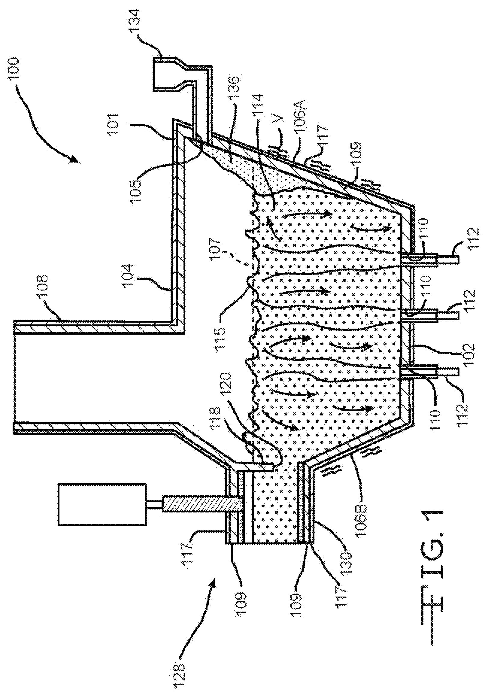
FIG. 1 depicts a side sectional view of a melter that may be utilized in conjunction with the examples of the technology described herein.
FIG. 2 depicts a side sectional view of a burner that may be utilized in conjunction with the examples of the technology described herein.
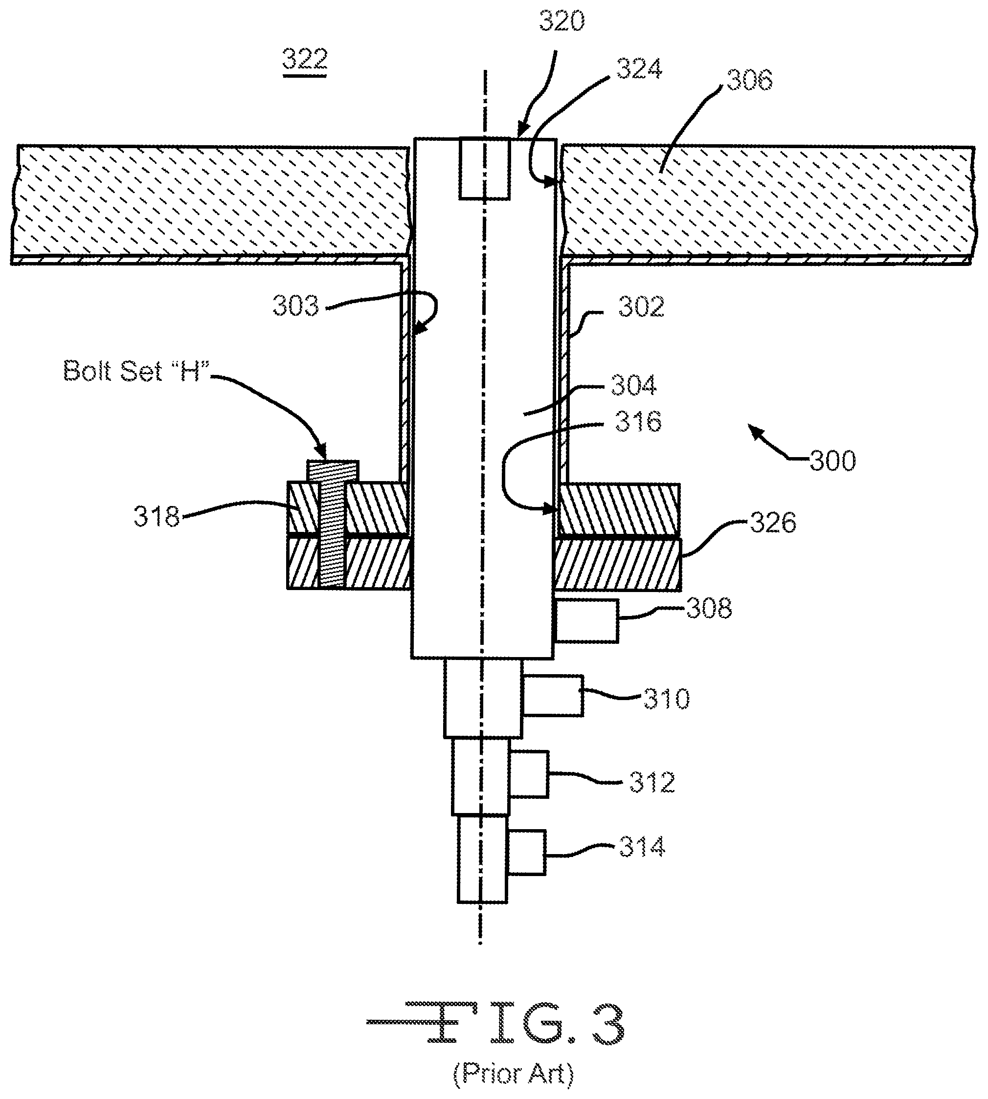
FIG. 3 depicts a side sectional view of a prior art burner mount.
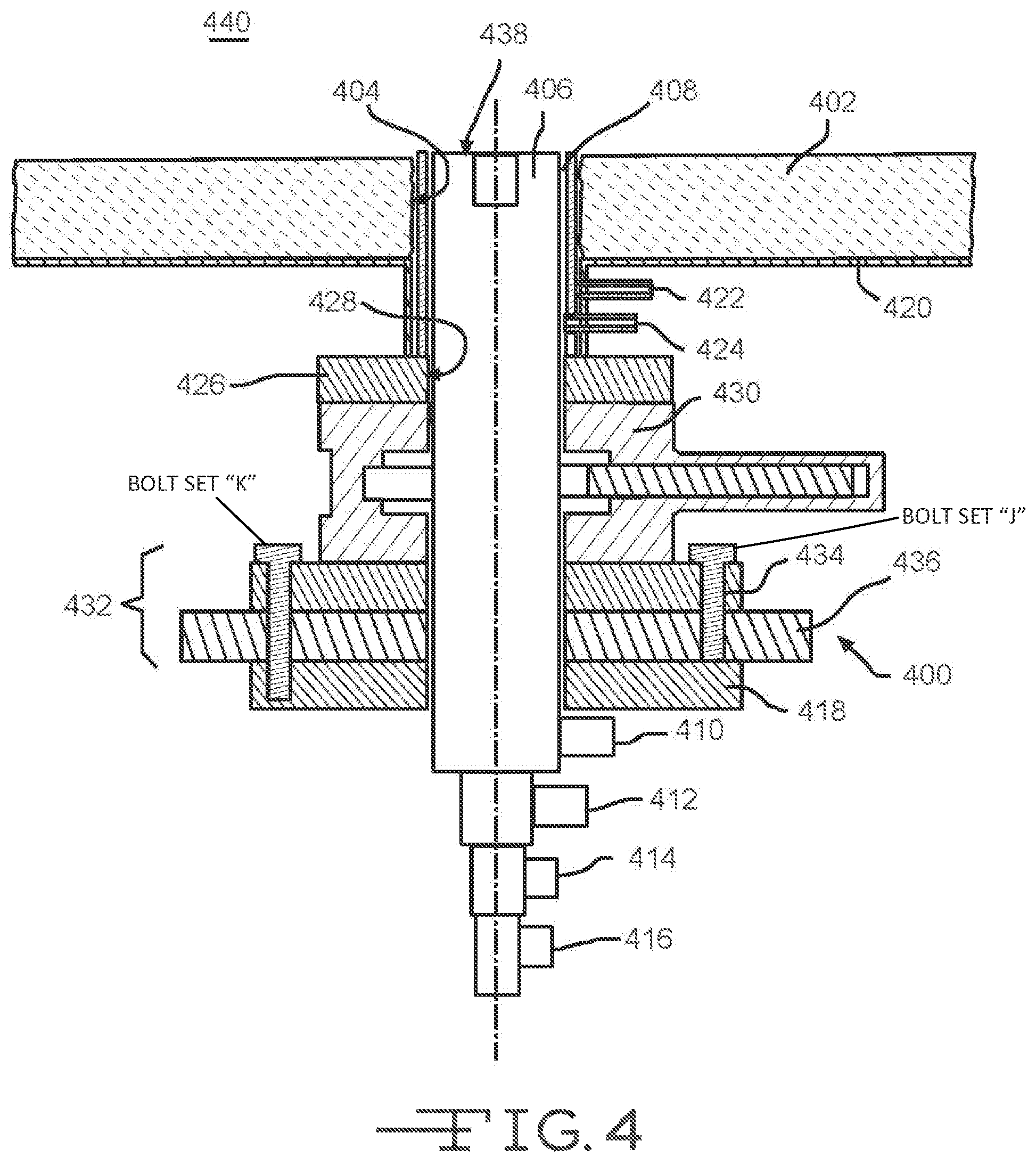
FIG. 4 depicts a partial side sectional view of a burner change-out system in accordance with an example of the present technology.
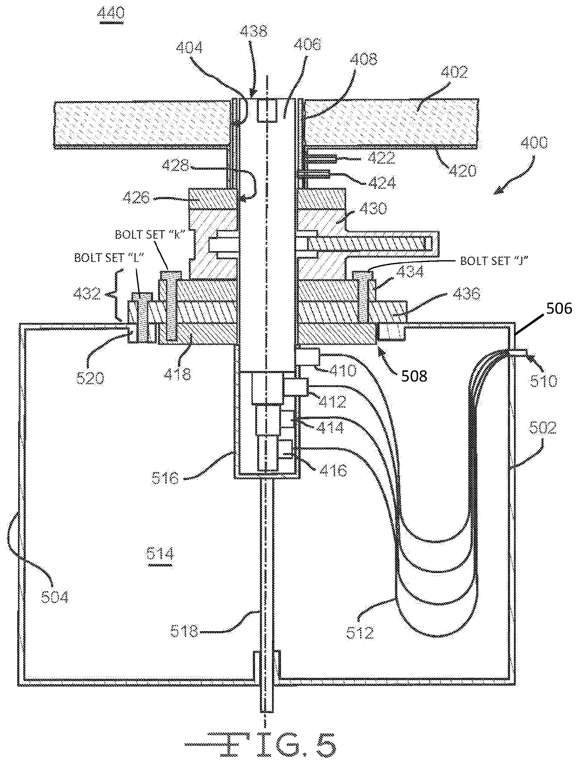
FIG. 5 depicts a side sectional view of a burner change-out system, having a burner in a first position.
FIG. 6 depicts a side sectional view of the burner change-out system of FIG. 5, having the burner in a second position.
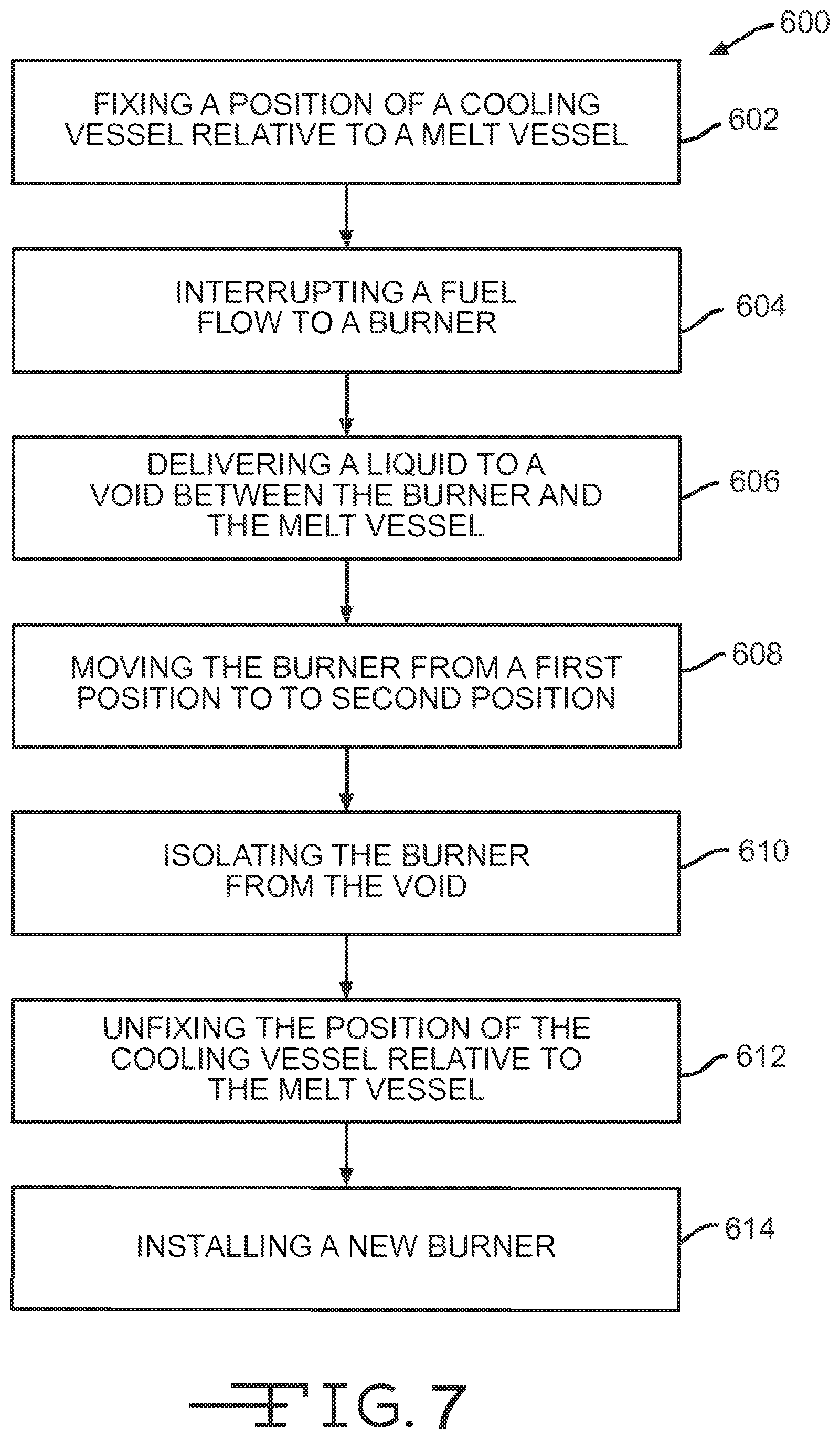
FIG. 7 depicts a method of replacing a burner in a melter system.
FIG. 8 depicts a method of replacing one burner in a multi-burner melter system during concurrent melt operations.
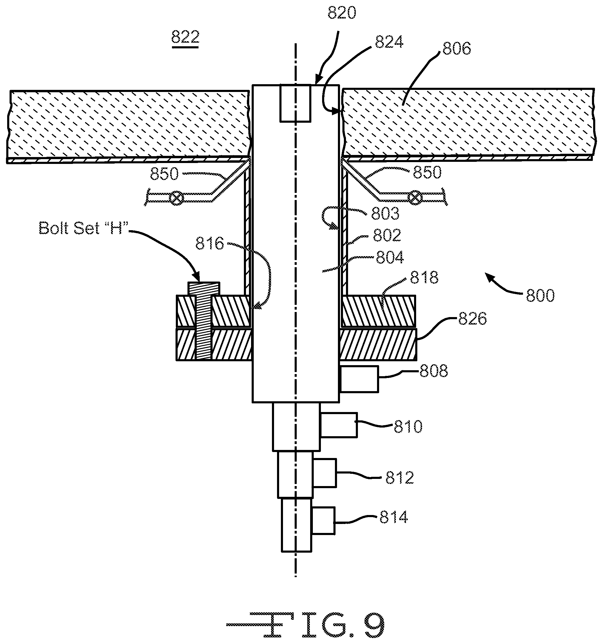
FIG. 9 depicts a partial side sectional view of a burner change-out system in accordance with another example of the present technology.
DETAILED DESCRIPTION
In the following description, numerous details are set forth to provide an understanding of various melter apparatus and process examples in accordance with the present disclosure. However, it will be understood by those skilled in the art that the melter apparatus and processes of using same may be practiced without these details and that numerous variations or modifications from the described examples may be possible which are nevertheless considered within the appended claims. All published patent applications and patents referenced herein are hereby incorporated by reference herein in their entireties.
FIG. 1 depicts a side sectional view of a melter system 100 that may be utilized in conjunction with the examples of the technology described herein. The melter system 100 is a submerged combustion melter (SCM) and is described in more detail in U.S. Patent Application Publication No. 2013/0283861, the disclosure of which is hereby incorporated by reference herein in its entirety. Melter apparatus or melt vessel 101 of FIG. 1 includes a floor 102, a roof or ceiling 104, a feed end wall 106A, a first portion of an exit end wall 1068, and a second portion of the exit end wall 106C. Each of the floor 102, the roof 104, and walls 106A, 106B, and 106C comprise a metal shell 117 and a refractory panel 109, some or all of which may be fluid-cooled. Exit end wall portion 106C may form an angle with respect to a skimmer 118.
The melt vessel 101 may be fluid cooled by using a gaseous, liquid, or combination thereof, heat transfer media. In certain examples, the wall may have a refractory liner at least between the panels and the molten glass. Certain systems may cool various components by directing a heat transfer fluid through those components. In certain examples, the refractory cooled-panels of the walls, the fluid-cooled skimmer, the fluid-cooled dam, the walls of the fluid-cooled transition channel, and the burners may be cooled by a heat transfer fluid selected from the group consisting of gaseous, liquid, or combinations of gaseous and liquid compositions that function or are capable of being modified to function as a heat transfer fluid. Different cooling fluids may be used in the various components, or separate portions of the same cooling composition may be employed in all components. Gaseous heat transfer fluids may be selected from air, including ambient air and treated air (for air treated to remove moisture), inert inorganic gases, such as nitrogen, argon, and helium, inert organic gases such as fluoro-, chloro- and chlorofluorocarbons, including perfluorinated versions, such as tetrafluoromethane, and hexafluoroethane, and tetrafluoroethylene, and the like, and mixtures of inert gases with small portions of non-inert gases, such as hydrogen. Heat transfer liquids may be selected from inert liquids, which may be organic, inorganic, or some combination thereof, for example, salt solutions, glycol solutions, oils and the like. Other possible heat transfer fluids include water, steam (if cooler than the oxygen manifold temperature), carbon dioxide, or mixtures thereof with nitrogen. Heat transfer fluids may be compositions including both gas and liquid phases, such as the higher chlorofluorocarbons.
The melt vessel 101 further includes an exhaust stack 108, and openings 110 for submerged combustion burners 112, which create during operation a highly turbulent melt matrix indicated at 114. Highly turbulent melt matrix 114 may have an uneven top surface 115 due to the nature of submerged combustion. An average level 107 is illustrated with a dashed line. In certain examples, burners 112 are positioned to emit combustion products into molten matrix in the melting zone 114 in a fashion so that the gases penetrate the melt generally perpendicularly to floor 102. In other examples, one or more burners 112 may emit combustion products into the melt at an angle to floor 102.
In an SCM, combustion gases emanate from burners 112 under the level of a molten matrix. The burners 112 may be floor-mounted, wall-mounted, or in melter examples comprising more than one submerged combustion burner, any combination thereof (for example, two floor mounted burners and one wall mounted burner). These combustion gases may be substantially gaseous mixtures of combusted fuel, any excess oxidant, and combustion products, such as oxides of carbon (such as carbon monoxide, carbon dioxide), oxides of nitrogen, oxides of sulfur, and water. Combustion products may include liquids and solids, for example soot and unburned liquid fuels.
A burner 112 may be an air-fuel burner that combusts one or more fuels with only air, or an oxy-fuel burner that combusts one or more fuels with either oxygen alone, or employs oxygen-enriched air, or some other combination of air and oxygen, including combustion burners where the primary oxidant is air, and secondary and tertiary oxidants are oxygen. Burners may be comprised of metal, ceramic, ceramic-lined metal, or combination thereof. Air in an air-fuel mixture may include ambient air as well as gases having the same molar concentration of oxygen as air. Oxygen-enriched air having an oxygen concentration greater than 121 mole percent may be used. Oxygen may include pure oxygen, such as industrial grade oxygen, food grade oxygen, and cryogenic oxygen. Oxygen-enriched air may have 50 mole percent or more oxygen, and in certain examples may be 90 mole percent or more oxygen. Oxidants such as air, oxygen-enriched air, and pure oxygen may be supplied from a pipeline, cylinders, storage facility, cryogenic air separation unit, membrane permeation separator, or adsorption unit.
The fuel burned by the burners may be a combustible composition (either in gaseous, liquid, or solid form, or any flowable combination of these) having a major portion of, for example, methane, natural gas, liquefied natural gas, propane, atomized oil, powders or the like. Contemplated fuels may include minor amounts of non-fuels therein, including oxidants, for purposes such as premixing the fuel with the oxidant, or atomizing liquid fuels.
At least some of the burners may be mounted below the melt vessel, and in certain examples the burners may be positioned in one or more parallel rows substantially perpendicular to a longitudinal axis of the melt vessel. In certain examples, the number of burners in each row may be proportional to width of the vessel. In certain examples the depth of the vessel may decrease as width of the vessel decreases. In certain other examples, an intermediate location may comprise a constant width zone positioned between an expanding zone and a narrowing zone of the vessel, in accordance with U.S. Patent Application Publication No. 2011/0308280, the disclosure of which is hereby incorporated by reference herein in its entirety.
Returning to FIG. 1, the initial raw material can be introduced into melt vessel 101 on a batch, semi-continuous or continuous basis. In some examples, a port 105 is arranged at end 106A of melt vessel 101 through which the initial raw material is introduced by a feeder 134. In some examples, a batch blanket 136 may form along wall 106A, as illustrated. Feed port 105 may be positioned above the average matrix melt level, indicated by dashed line 107. The amount of the initial raw material introduced into melt vessel 101 is generally a function of, for example, the capacity and operating conditions of melt vessel 101 as well as the rate at which the molten material is removed from melt vessel 101.
The initial raw material may include any material suitable for forming a molten matrix, such as glass and/or inorganic non-metallic feedstocks such as rock (basalt) and mineral wool (stone wool). With regard to glass matrices, specifically, limestone, glass, sand, soda ash, feldspar and mixtures thereof can be utilized. In one example, a glass composition for producing glass fibers is "E-glass," which typically includes 52-56% SiO.sub.2, 12-16% Al.sub.2O.sub.3, 0-0.8% Fe.sub.2O.sub.3, 16-25% CaO, 0-6% MgO, 0-10% B.sub.2O.sub.3, 0-2% Na.sub.2O+K.sub.2O, 0-1.5% TiO.sub.2 and 0-1% F.sub.2. Other glass compositions may be used, such as those described in U.S. Published Patent Application No. 2008/0276652, the disclosure of which is hereby incorporated by reference herein in its entirety. The initial raw material can be provided in any form such as, for example, relatively small particles.
As noted herein, submerged combustion burners may produce violent turbulence of the molten matrix and may result in a high degree of mechanical energy (e.g., vibration V in FIG. 1) in the submerged combustion melter that, without modification, is undesirably transferred to the conditioning channel. Vibration may be due to one or more impacts from sloshing of the molten matrix, pulsing of the submerged combustion burners, popping of large bubbles above submerged burners, ejection of the molten matrix from main matrix melt against the walls and ceiling of melt vessel 101, and the like. Melter exit structure 128 comprises a fluid-cooled transition channel 30, having generally rectangular cross-section in melt vessel 101, although any other cross-section would suffice, such as hexagonal, trapezoidal, oval, circular, and the like. Regardless of cross-sectional shape, fluid-cooled transition channel 130 is configured to form a frozen matrix layer or highly viscous matrix layer, or combination thereof, on inner surfaces of fluid-cooled transition channel 130 and thus protect melter exit structure 128 from the mechanical energy imparted from the melt vessel 101 to melter exit structure 128.
FIG. 2 depicts a side sectional view of a burner 200 that may be utilized in conjunction with the examples of the technology described herein. The burner 200 is an SCM burner having a fluid-cooled portion 202 having a burner tip 204 attached to a burner body 206. A burner main flange 208 connects the burner to an SCM superstructure or flange, illustrated below. Burner body 206 has an external conduit 210, a first internal conduit 212, a second internal conduit 214, and end plates 216, 218. A coolant fluid inlet conduit 220 is provided, along with a coolant fluid exit conduit 222, allowing ingress of a cool coolant fluid as indicated by an arrow CFI, and warmed coolant fluid egress, as indicated by an arrow CFO, respectively. A first annulus 211 is thus formed between substantially concentric external conduit 210 and first internal conduit 212, and a second annulus 213 is formed between substantially concentric first and second internal conduits 212, 214. A proximal end 224 of second internal conduit 214 may be sized to allow insertion of a fuel or oxidant conduit 215 (depending on the burner arrangement), which may or may not include a distal end nozzle 217. When conduit 215 and optional nozzle 217 are inserted internal of second internal conduit 214, a third annulus is formed there between. In certain examples, oxidant flows through the third annulus, while one or more fuels flow through conduit 215, entering through a port 244. In certain other examples, one or more fuels flow through the third annulus, while oxidant flows through conduit 215, entering through port 244.
The fluid-cooled portion 202 of the burner 200 includes a ceramic or other material insert 226 fitted to the distal end of first internal conduit 212. Insert 226 has a shape similar to but smaller than burner tip 204, allowing coolant fluid to pass between burner tip 204 and insert 226, thus cooling burner tip 204. Burner tip 204 includes an inner wall 228, an outer wall 230, and a crown 232 connecting inner wall 228 and outer wall 230. In prior art burners, welds at locations 234 and 236, and optionally at 238, 240 and 242, connect burner tip 204 to external conduit 210 and second internal conduit 214, using conventional weld materials to weld together similar base metal parts, such as carbon steel, stainless steel, or titanium. Despite the use of coolant and even titanium (which ordinarily is considered quite corrosion-resistant), the operating life of burners as illustrated and described in relation to FIG. 2 are very limited in the SCM environment, where temperatures of the molten matrix may reach 1300.degree. C., and the turbulence of the molten matrix caused by the burners themselves as well as combustion gases contribute to form a highly erosive environment in contact with the burner tip. As such, the burners used in SCM applications have to be replaced often. Other examples of SCM burners that can be used in conjunction with the technologies described herein are described in PCT Application Publication No. 2014/189501, the disclosure of which is hereby incorporated by reference herein in its entirety. SCM melters that utilize so-called dry tip burners can also benefit from the technologies described herein. Application of the technologies described herein to such dry tip burners will be apparent to a person of skill in the art. For clarity, however, the replacement or change-out technologies described in the present application will be described in the context of water-cooled SCM burners.
FIG. 3 depicts a side sectional view of a prior art burner mount 300. The mount 300 includes a flange 302 that supports a burner 304, such as described in FIG. 2, in an interior void 303 thereof. The flange 302 is secured to an underside of a melt vessel or refractory 306, such as described in conjunction with the melter system of FIG. 1. Typically, the burner 304 is inserted into the mount 300 when the melt vessel 306 is empty and the melter system is out of service. The burner 304 includes a number of connections, for example an oxidizer connection 308 and a fuel connection 310. Burners 304 that utilize liquid cooling also include a cooling fluid supply connection 312 and a cooling liquid return connection 314. In examples, the cooling fluid can be water or other liquid coolants. The burner 304 penetrates a holder opening 316 in a burner holder 318 that fixes a position of the burner 304 within the flange 302, such that a burner tip 320 penetrates into or proximate an interior volume 322 of the vessel 306 at a vessel opening 324. A main flange or ring 326 secured to the burner 304 provides a point of connection with the burner holder 318. One or more bolts (typically a plurality are utilized) can be used to secure the position of the burner 304 in the flange 302. These bolts are depicted as bolt set H. As can be seen, if the burner 304 requires replacement or repair, it cannot be removed with the melter system in service, as there would be no mechanism to close either the vessel opening 324 or the holder opening 316. If removed, the molten matrix would drain through the openings 324, 316, thereby causing an unsafe condition and loss of matrix.
The technologies described herein include components to enable swapping- or changing-out a submerged combustion burner without the need to shut down the melter system, drain and cool the vessel, remove and replace the burner, reheat the vessel, and restart melting operations. The ability to remove and replace the burner while keeping the melter system in operation extends the life of components utilized therein and significantly reduces lost production time. The following description and figures depict exemplary change-out systems in more detail.
FIG. 4 depicts a partial side sectional view of a burner change-out system 400 in accordance with an example of the present technology. The system 400 includes a number of components. As with the mount 300 depicted in FIG. 3, the change-out system 400 is utilized in conjunction with an SCM melt vessel or refractory 402 that defines a vessel opening 404 for receipt of a burner 406. When the burner 406 is disposed in the vessel opening 404, an annular void 408 is formed therebetween. As above, the burner 406 includes a number of connections, for example an oxidizer connection 410 and a fuel connection 412. Burners 406 that also utilize liquid cooling include a cooling fluid supply connection 414 and a cooling liquid return connection 416, although the technologies described herein are not limited to liquid-cooled burners. A burner main flange or ring 418 is connected to the burner 406 to support the burner 406 as described herein. The change-out system 400 includes a flange 420 that is configured to be secured to an underside of the vessel 402. The flange 420 includes two fluid ports 422, 424 that are used to circulate a cooling liquid, such as the types described above, into the void 408 during burner change-out operations. In the depicted example, fluid inlet port 422 and fluid outlet port 424 are normally closed during melt operations. A burner holder 426 forms a bottom of the flange 420 and defines a holder opening 428 for receiving the burner 406.
An upper side of a valve 430 is disposed proximate the flange 420. In FIG. 4, the valve 430 is a gate valve, although other valve types can be utilized. A bottom side of the valve 430 is disposed proximate a collar 432 that includes a valve plate 434 and a change-out adapter 436. The collar 432 connects the various elements of the change-out system 400 as described further herein. During operation of the melter system, the gate valve 430 is normally open, as depicted, due to the presence of the burner 406. The burner 406 is depicted in a first position, such that a tip 438 thereof is disposed proximate an interior 440 of the vessel 402. One or more bolts (e.g., bolt set J) secure the valve plate 434 to the change-out adapter 436. Additionally, one or more bolts (e.g., bolt set K) secure the valve plate 434 to the burner ring 418. Both bolt sets J and K are engaged during normal melt system operations. Each of the flange 420, burner holder 426, valve 430, and collar 432 define an interior void or volume. These voids or volumes are substantially aligned so as to accommodate the burner 406 throughout the removal and insertion processes described below.
FIG. 5 depicts a side sectional view of a burner change-out system 400, having the burner 406 in a first position. A number of components of the system 400 are described above with regard to FIG. 4 and as such are not necessarily described further. The change-out system 400 includes a cooling box or vessel 502 that is used to remove and cool the burner 406 after removal from the melt vessel 402. The cooling vessel 502 includes a housing 504 having a plurality of walls 506, one of which (in this case, an upper wall) defines a burner port 508. In the depicted example, the burner port 508 is sized to receive the burner ring 418. The cooling vessel 502 can also define one or more hose openings 510 that allow passage of one or more hoses 512 that serve the various connections 410-416. As the cooling vessel interior 514 is filled with cooling water or other coolant, the hose opening(s) 508 are sealed. Additional hose openings can be utilized to circulate cooling fluid within the cooling vessel 502 during change-out operations. A support element 516 is movable within the cooling vessel interior 514 via an actuator or lift assembly 518. Prior to removal of the burner 406, the change-out adapter 436 is connected to a rim 520 about the burner port 508 with bolt set L.
FIG. 5 depicts the burner 406 in a first, or upper position, where the burner 406 is positioned so as to deliver energy in the form of heat to the melt matrix disposed in the vessel 402. To remove the burner 406 from service in the SCM melter, the cooling vessel 502 is first connected to the collar 432 (e.g., via the bolt set L). The cooling vessel 502 is filled with water or other coolant and/or the water/coolant may be circulated therethrough. Once the cooling vessel 502 is fixed relative to the burner 406, at least a portion of the burner 406 is disposed within or supported by the support element 516. Fuel flow to the burner 406 is terminated or interrupted and heat energy emitted by the burner 406 begins to dissipate. Around the time fuel flow is terminated, water or other coolant liquid is introduced, injected, or otherwise pumped through the fluid inlet port 422 into the annular void 408 between the burner 406 and the vessel opening 404. By cooling the temperature in the void 408 (due to termination of fuel flow and initiation of cooling fluid flow), a skull or hardened shell is formed over the burner 406. This skull is essentially a non-molten portion of the matrix within the vessel 402 and prevents molten matrix from contacting the burner 406. Cooling fluid can be circulated via the fluid outlet port 424 to maintain the temperature in the void 408 at a level so as to maintain the integrity of the skull.
FIG. 6 depicts a side sectional view of the burner change-out system 400 of FIG. 5, having the burner 406 in a second position. A number of components of the system 400 are described above with regard to FIGS. 4 and 5 and as such are not necessarily described further. The hoses depicted in FIG. 5 are not depicted for clarity. Here, the burner 406 is depicted in a lower, or second position, where the burner 406 is disposed distal from the melt vessel 402. Once the skull 550 has achieved a sufficient strength, the burner 406 may be lowered to the depicted second position. Skull strength may be estimated by measuring a temperature of the water or coolant at the fluid outlet port 424. Since the water or coolant is being circulated within the void 408, a relatively consistent temperature can provide an estimate of temperature proximate the skull 550, and as such, whether it is safe to begin the burner removal process. Bolt set K (FIG. 5) is then disconnected. Water circulation continues as the support element 516 is lowered by the actuator 518. As the burner 406 is lowered, the gate valve 430 is closed once the tip 438 drops below the level of the valve 430. This isolates the void 408 from the burner 406. With the valve 430 closed, the interior 514 of the cooling vessel 502 is substantially isolated from an exterior of the cooling vessel 502 (were the valve 430 to be disconnected from the burner holder 426). In examples, disconnecting the valve 430 from the holder 426 may be desirable because it keeps the hot burner 406 contained until it is safe enough to handle. As the burner 406 is lowered, prior to the gate valve 430 closing, some water or coolant from the fluid inlet port 422 may leak past the valve 430 and into the cooling vessel 502, via the collar 432. As apparent from FIG. 6, the volume of the burner 406 now disposed within the cooling vessel 502 is greater than the volume of the burner 406 disposed in the cooling vessel 502 in FIG. 5. As such, cooling of the burner 406 is accelerated.
Thereafter, the cooling vessel 502 can be unfixed relative to the melt vessel 402 (e.g., by disconnecting bolt set L). A new burner can then be installed via a reverse process to that described above. For example, a new burner 406 may be placed on the support element 516 and a position of the cooling vessel 502 fixed relative to the melt vessel 402 (e.g., by securing bolt set L). As the actuator 518 raises the support element 516 and burner 406, the gate valve 430 is opened. Raising of the burner 406 continues until the tip 438 is proximate the melt vessel 402. Once in the desired position, the burner ring 418 can be secured in place (e.g., via bolt set K). With the burner ring 418 secured, bolt set L can be disconnected, thus releasing the position of the cooling vessel 502 relative to the melt vessel 402.
FIG. 7 depicts a method 600 of replacing a burner in a melter system. The method 600 begins with operation 602, which includes fixing a position of a cooling vessel relative to a melt vessel. Depending on the clearance below the melt vessel, the cooling vessel can be lifted into position via a lift system, jacks, or other implements, so as to substantially surround a burner of the melt vessel. Once in position, one or more bolt sets or fixing elements (e.g., clamps) can fix or otherwise secure the cooling vessel. In operation 604, fuel flow to the burner is interrupted or terminated. Substantially contemporaneously therewith, operation 606 begins. In operation 606, a cooling liquid is delivered to an annular void between the burner and the melt vessel. Since the void is in fluidic communication with an interior of the melt vessel, this causes the molten matrix disposed proximate the burner tip to harden or solidify into a skull over the inactive burner. In operation 608, the burner is moved from a first position (where the tip is disposed proximate the melt vessel) to a second positon (where the burner is disposed distal the melt vessel). In the position distal the melt vessel, a larger volume of the burner is disposed within the cooling vessel, so as to more effectively cool the burner. During moving operation 608, liquid delivery operation 606 continues, so as to maintain the matrix skull. Once the burner is in the second position, the burner is isolated from the void at operation 610. In examples, isolation of the burner from the void includes closing a gate valve disposed between the void and the burner. Thereafter, in operation 612, the position of the cooling vessel relative to the melt vessel is unfixed. This may include disconnecting one or more sets of bolts and lowering the cooling vessel. The burner can then be removed from the cooling vessel and a new burner disposed in the cooling vessel. Thereafter, the new burner can be installed in operation 614, which includes performing the above steps in substantially reverse order.
FIG. 8 depicts a method 700 of replacing one burner in a multi-burner melter system during concurrent melt operations. The method 700 begins with emitting heat energy from a first burner (operation 702) and a second burner (operation 704) so as to melt a material disposed in an SCM melter system. In operation 706, energy emission from the first burner is terminated while, in operation 708, energy emission from the second burner is maintained. In operation 710, a cooling fluid is injected into a void proximate the melt vessel and the first burner, so as to form a skull of material proximate the first burner. Once the skull is formed, the first burner is removed from the melt vessel while the second burner continues to emit heat energy, in operation 712. As the first burner is being removed, it is lowered into a cooling vessel, so as to accelerate cooling thereof, operation 714. In operation 716, a third burner can be placed in a position formerly occupied by the first burner. In this context, a third burner does not necessarily mean a new burner or a different burner, but may be the same first burner subsequent to certain maintenance, inspection, and/or repair.
FIG. 9 depicts a partial side sectional view of a burner change-out system 800 in accordance with another example of the present technology. The burner change out system 800 utilizes a flange 802 similar to the prior art flange of FIG. 3 above. The flange, however, also includes one or more coolant connection lines 850 that are used to form a skull in a molten material. In more detail, the system 800 includes a flange 802 that supports a burner 804 in an interior void 803 thereof. The flange 802 is secured to an underside of a melt vessel or refractory 806. The burner 804 includes a number of connections, for example an oxidizer connection 808 and a fuel connection 810. Burners 804 that utilize liquid cooling also include a cooling fluid supply connection 812 and a cooling liquid return connection 814. The burner 804 penetrates a holder opening 816 in a burner holder 818 that fixes a position of the burner 804 within the flange 802, such that a burner tip 820 penetrates into or proximate an interior volume 822 of the vessel 806 at a vessel opening 824. A main flange or ring 826 secured to the burner 804 provides a point of connection with the burner holder 818. One or more bolts (typically a plurality are utilized) can be used to secure the position of the burner 804 in the flange 802. These bolts are depicted as bolt set H.
Coolant connection lines 850 are installed on the flange 802 pointing at an upward angle toward the vessel 806. In examples, four connection lines 850 can be utilized and include valves to control coolant flow during change-out procedures. To change-out the burner 804, fuel to the burner 804 may be turned off and, if desired, and air purge may be performed. Coolant is then delivered through the coolant connection lines 850 so as to form a skull above the vessel opening 824. To aid in forming the skull, adjacent burners in a multi-burner system can be turned off or the heat emission from them can be reduced. Integrity of the skull may be determined by measuring a temperature proximate the vessel opening or by viewing the interior of the flange 802 through a sight tube (not shown). Once integrity of the skull is confirmed, one or more of the various connections 810-816 can be disconnected from their supply hoses. These supply hoses can then be connected to similar connections on a new burner. Bolt set H can be disconnected, the existing burner 804 removed, and a new burner inserted into the flange 802. In a specific example, a subset of bolt set H may be disconnected before connecting making hose connections to the new burner. Once the bolt set H is reconnected for the new burner, the oxidizer gas flow can be reestablished to provide a positive pressure above the new burner and then the coolant spray can be terminated, so as to allow the skull to re-melt into the matrix. As the skull re-melts, the oxidizer gas flow will increase and the back pressure decrease. This indicates a re-melting of the skull and an opening of a flow passage for the oxidizer gas into the molten matrix. Once the skull has melted (this may be confirmed visually through the sight glass or by an indication of flow from the burner oxidizer gas up into the molten matrix from the flow sensors and pressure gages), fuel flow to the burner may be restarted. A drain tube on the side of the flange 802 is used to drain any coolant or condensed vapor that collects after creating/maintaining the frozen skull over the burner opening. This drain tube has a valve that allows coolant from the coolant connection lines 850 to drain as needed but can be closed when not needed to prevent a passage for combustion gases during normal operation. One aspect of this drain tube is the use of multiple valves and a secondary collection container to allow drainage but maintain a sealed enclosure.
This disclosure described some aspects of the present technology with reference to the accompanying drawings, in which only some of the possible aspects were shown. Other aspects can, however, be embodied in many different forms and should not be construed as limited to the aspects set forth herein. Rather, these aspects were provided so that this disclosure was thorough and complete and fully conveyed the scope of the possible aspects to those skilled in the art.
Although specific aspects were described herein, the scope of the technology is not limited to those specific aspects. One skilled in the art will recognize other aspects or improvements that are within the scope of the present technology. Therefore, the specific structure, acts, or media are disclosed only as illustrative aspects. The scope of the technology is defined by the following claims and any equivalents therein.
* * * * *
References
D00000
D00001
D00002
D00003
D00004
D00005
D00006
D00007
D00008
D00009
XML
uspto.report is an independent third-party trademark research tool that is not affiliated, endorsed, or sponsored by the United States Patent and Trademark Office (USPTO) or any other governmental organization. The information provided by uspto.report is based on publicly available data at the time of writing and is intended for informational purposes only.
While we strive to provide accurate and up-to-date information, we do not guarantee the accuracy, completeness, reliability, or suitability of the information displayed on this site. The use of this site is at your own risk. Any reliance you place on such information is therefore strictly at your own risk.
All official trademark data, including owner information, should be verified by visiting the official USPTO website at www.uspto.gov. This site is not intended to replace professional legal advice and should not be used as a substitute for consulting with a legal professional who is knowledgeable about trademark law.