Support structures for golf club head
DeMille , et al. November 17, 2
U.S. patent number 10,835,789 [Application Number 16/836,682] was granted by the patent office on 2020-11-17 for support structures for golf club head. This patent grant is currently assigned to Callaway Golf Company. The grantee listed for this patent is Callaway Golf Company. Invention is credited to Brandon D. DeMille, William C. Watson.


| United States Patent | 10,835,789 |
| DeMille , et al. | November 17, 2020 |
Support structures for golf club head
Abstract
A golf club head, preferably a putter head, comprising at least one structural support member is disclosed herein. The structural support member has a smooth, organic-looking aesthetic, with a continuously changing curvature along its spline and at least one surface, and preferably connects one portion of the golf club head to another portion. Where the support member connects to other portions of the golf club head, the surfaces of the member have a curvature that changes smoothly and continuously, lacking any sharp corners.
| Inventors: | DeMille; Brandon D. (Carlsbad, CA), Watson; William C. (Menifee, CA) | ||||||||||
|---|---|---|---|---|---|---|---|---|---|---|---|
| Applicant: |
|
||||||||||
| Assignee: | Callaway Golf Company
(Carlsbad, CA) |
||||||||||
| Family ID: | 73263962 | ||||||||||
| Appl. No.: | 16/836,682 | ||||||||||
| Filed: | March 31, 2020 |
Related U.S. Patent Documents
| Application Number | Filing Date | Patent Number | Issue Date | ||
|---|---|---|---|---|---|
| 29703641 | Aug 28, 2019 | ||||
| 29673358 | Dec 13, 2018 | D880631 | |||
| 62892924 | Aug 28, 2019 | ||||
| Current U.S. Class: | 1/1 |
| Current CPC Class: | A63B 53/0487 (20130101); A63B 60/50 (20151001); A63B 53/0408 (20200801); A63B 53/045 (20200801); A63B 53/0412 (20200801) |
| Current International Class: | A63B 53/04 (20150101) |
| Field of Search: | ;473/324-350 |
References Cited [Referenced By]
U.S. Patent Documents
| 1658581 | February 1928 | Tobia |
| 4010958 | March 1977 | Long |
| 4313607 | February 1982 | Thompson |
| 4511145 | April 1985 | Schmidt |
| 5290032 | March 1994 | Fenton |
| 5295689 | March 1994 | Lundberg |
| 5447307 | September 1995 | Antonious |
| 5451058 | September 1995 | Price |
| 5549297 | August 1996 | Mahaffey |
| 5839975 | November 1998 | Lundberg |
| 6309311 | October 2001 | Lu |
| 6558271 | May 2003 | Beach |
| 7077758 | July 2006 | Rohrer |
| 7371185 | May 2008 | Rohrer |
| 7384345 | June 2008 | Sherman |
| 7588499 | September 2009 | Tateno |
| 7854665 | December 2010 | Dewhurst |
| 8070623 | December 2011 | Stites |
| 8142308 | March 2012 | Gillig |
| 8475292 | July 2013 | Rahrig |
| 8608585 | December 2013 | Stites |
| 8915794 | December 2014 | Stites |
| 9393471 | July 2016 | Beno |
| 9393473 | July 2016 | Knight |
| 9597558 | March 2017 | Seluga |
| 9597561 | March 2017 | Seluga |
| 9821199 | November 2017 | Seluga |
| 9855475 | January 2018 | Motokawa |
| 9889349 | February 2018 | Seluga |
| 9901794 | February 2018 | Beno |
| 9931550 | April 2018 | Seluga |
| 9987527 | June 2018 | Myers |
| 10258846 | April 2019 | Nunez |
| 10384107 | August 2019 | Knight |
| 10512826 | December 2019 | Frederickson |
| 10532258 | January 2020 | Seluga |
| 10617920 | April 2020 | Nunez |
Attorney, Agent or Firm: Hanovice; Rebecca Catania; Michael Lari; Sonia
Parent Case Text
CROSS REFERENCES TO RELATED APPLICATIONS
The present application claims priority to U.S. Provisional Patent Application No. 62/892,924, filed on Aug. 28, 2019, and is a continuation-in-part of U.S. Design patent application Ser. No. 29/673,358, filed on Dec. 13, 2018, and issued on Apr. 7, 2020, as U.S. Design Pat. No. D880,631, and is a continuation-in-part of U.S. Design patent application Ser. No. 29/703,641, filed on Aug. 28, 2019, the disclosure of each of which is hereby incorporated by reference in its entirety herein.
Claims
We claim:
1. A golf club head comprising: a body comprising face, a sole portion extending from a bottom edge of the face, and a top portion extending from a top edge of the face; and at least one support member extending from at least one of the face, sole portion, and top portion, wherein the at least one support member comprises a first end, a second end, a surface, an equivalent diameter, a spline, and a cross-sectional shape, wherein the equivalent diameter D.sub.E of a cross section taken at any point along the spline is calculated using the formula D.sub.E=(4*A/pi){circumflex over ( )}(1/2), wherein A is an area of a cross-section of the support member, wherein the at least one support member has a length that is greater than D.sub.EA, wherein D.sub.EA is defined as the average equivalent diameter along the length of the entire support member, wherein a curvature of the surface continuously changes from the first end to the second end, wherein the equivalent diameter is always greater than 0.010 inch and less than 1.000 inch, and wherein the spline is curved and has a length that is at least three times the value of the average equivalent diameter D.sub.EA.
2. The golf club head of claim 1, wherein the golf club head is a putter head, and wherein the at least one support member connects the sole portion to the top portion.
3. The golf club head of claim 2, wherein the at least one support member connects to the sole portion at a first connection region and to the top portion at a second connection region, and wherein at least one of the first and second connection region has a constant surface curvature.
4. The golf club head of claim 1, wherein a volume occupied by the at least one support member is no greater than 75% of a volume that would be occupied if an entire volume of the golf club head between the top portion and the sole portion were a solid.
5. The golf club head of claim 1, wherein the equivalent diameter is no less than 0.025 inch and no more than 0.500 inch at any point taken along the length of the support member.
6. The golf club head of claim 5, wherein the equivalent diameter is no less than 0.050 inch and no more than 0.250 inch at any point taken along the length of the support member.
7. The golf club head of claim 1, wherein the equivalent diameter changes continuously along the entire length of the spline.
8. The golf club head of claim 1, wherein the cross-sectional shape changes continuously along the entire length of the spline.
9. The golf club head of claim 1, wherein the at least one support member comprises first and second support members, and wherein the first support member is connected with the second support member.
10. The golf club head of claim 1, wherein the at least one support member does not comprise any sharp corners.
11. The golf club head of claim 1, wherein the at least one support member does not comprise any fillets with constant surface curvature.
12. A putter head comprising: a face with an upper edge, a striking surface, and a lower edge; a crown portion extending from the upper edge; a sole portion extending from the lower edge; and at least one support structure connecting the crown portion to the sole portion, wherein the at least one support structure comprises a length, a width, a first end, a second end, a surface, a variable equivalent diameter, a spline, and a variable cross-sectional shape, wherein the length is greater than the average equivalent diameter, wherein the equivalent diameter D.sub.E of a cross section taken at any point along the spline is calculated using the formula D.sub.E=(4*A/pi){circumflex over ( )}(1/2), wherein A is an area of a cross-section of the support member, wherein the curvature of all surfaces continuously changes from the first end to the second end, wherein the equivalent diameter is greater than 0.010 inch and less than 1.000 inch and changes continuously along the length of the spline, wherein the spline is curved and has a length that is at least three times the value of the equivalent diameter, and wherein the cross-sectional shape changes continuously along the length of the spline.
13. The putter head of claim 12, wherein the at least one support member extends at an angle from the sole portion, and wherein the angle is less than 75.degree..
14. The putter head of claim 12, wherein the at least one support member does not comprise any sharp corners or simple fillets with constant surface structure.
15. The putter head of claim 12, wherein the at least one support member comprises at least six support members, and wherein each of the support members extends at an angle with respect to the crown portion and the sole portion.
16. The putter head of claim 12, wherein the at least one support member connects with the sole portion at a first connection region, wherein the at least one support member connects with the crown portion at a second connection region, and wherein at least one of the first and second connection region has a constant surface curvature.
17. The putter head of claim 12, wherein the equivalent diameter is no less than 0.025 inch and no more than 0.500 inch at any point taken along the length of the support member.
18. The putter head of claim 17, wherein the equivalent diameter is no less than 0.050 inch and no more than 0.250 inch at any point taken along the length of the support member.
Description
STATEMENT REGARDING FEDERALLY SPONSORED RESEARCH OR DEVELOPMENT
Not Applicable
BACKGROUND OF THE INVENTION
Field of the Invention
The present invention relates to a golf club head, particularly a putter, with improved structures supporting upper and lower portions of the head.
Description of the Related Art
Traditional CAD modeling techniques used to design golf club heads, and particularly putters, lend themselves to certain, angular styles or appearances. Organic-looking, smoothly curved features are more time consuming and difficult to create than traditional, angled connectors. As a result, support structures created with traditional modeling techniques tend to have common characteristics. Specifically, as shown in FIGS. 1-3, tangency T between neighboring surfaces is common, but these transitions do not typically have smooth curvatures, especially where two or more slender structural elements intersect. In fact, as shown in FIGS. 4-5, the surface curvature changes along the spline of the structural elements are discrete. Furthermore, these traditional connections are subject to increased strain and breakage. Therefore, there is a need for a golf club head, and particularly a putter, with improved structural support members and connectivity between those support members and other parts of the golf club head.
BRIEF SUMMARY OF THE INVENTION
The present invention is directed to a golf club head, and particularly a putter, comprising support structures that: (1) are less susceptible to stress concentrations during the use of the structural part or component; (2) allow for improved flow and reduced porosity in investment casting operations; (3) allow for improved flow and reduced porosity in plastic injection molding, metal injection molding, and compression molding; (4) are less susceptible to local stress concentrations and cracking during sintering; and/or (5) are less susceptible to local stress concentrations and cracking during the build process for laser-based 3D printing methods, like direct metal laser melting (DMLM) or direct metal laser sintering (DMLS). The support structures of the present invention have an "organic" appearance that is not found in prior art structural golf club parts.
Another aspect of the present invention is a golf club head comprising a body comprising face, a sole portion extending from a bottom edge of the face, and a top portion extending from a top edge of the face, and at least one support member extending from at least one of the face, sole portion, and top portion, wherein the at least one support member comprises a first end, a second end, a surface, an equivalent diameter, a spline, and a cross-sectional shape, wherein the equivalent diameter D.sub.E of a cross section taken at any point along the spline is calculated using the formula D.sub.E=(4*A/pi){circumflex over ( )}(1/2), wherein A is an area of a cross-section of the support member, wherein the at least one support member has a length that is greater than D.sub.EA, wherein D.sub.EA is defined as the average equivalent diameter along the length of the entire support member, wherein a curvature of the surface continuously changes from the first end to the second end, wherein the equivalent diameter is always greater than 0.010 inch and less than 1.000 inch, and wherein the spline is curved and has a length that is at least three times the value of the average equivalent diameter D.sub.EA. In some embodiments, the golf club head may be a putter head, and the at least one support member may connect the sole portion to the top portion. In a further embodiment, the at least one support member may connect to the sole portion at a first connection region and to the top portion at a second connection region, and at least one of the first and second connection region may have a constant surface curvature.
In other embodiments, a volume occupied by the at least one support member may be no greater than 75% of a volume that would be occupied if an entire volume of the golf club head between the top portion and the sole portion were a solid. In still other embodiments, the equivalent diameter may be no less than 0.025 inch and no more than 0.500 inch at any point taken along the length of the support member. In a further embodiment, the equivalent diameter may be no less than 0.050 inch and no more than 0.250 inch at any point taken along the length of the support member. In yet another embodiment, the equivalent diameter may change continuously along the entire length of the spline. In yet another embodiment, the cross-sectional shape may change continuously along the entire length of the spline. In a further embodiment, the at least one support member may comprise first and second support members, and the first support member may be connected with the second support member. In another embodiment, the at least one support member may not comprise any sharp corners. In any of the embodiments, the at least one support member may not comprise any fillets with constant surface curvature.
Yet another aspect of the present invention is a putter head comprising a face with an upper edge, a striking surface, and a lower edge, a crown portion extending from the upper edge, a sole portion extending from the lower edge, and at least one support structure connecting the crown portion to the sole portion, wherein the at least one support structure comprises a length, a width, a first end, a second end, a surface, a variable equivalent diameter, a spline, and a variable cross-sectional shape, wherein the length is greater than the average equivalent diameter, wherein the equivalent diameter D.sub.E of a cross section taken at any point along the spline is calculated using the formula D.sub.E=(4*A/pi){circumflex over ( )}(1/2), wherein A is an area of a cross-section of the support member, wherein the curvature of all surfaces continuously changes from the first end to the second end, wherein the equivalent diameter is greater than 0.010 inch and less than 1.000 inch and changes continuously along the length of the spline, wherein the spline is curved and has a length that is at least three times the value of the equivalent diameter, and wherein the cross-sectional shape changes continuously along the length of the spline.
In some embodiments, the at least one support member may extend at an angle of less than 75.degree. from the sole portion. In other embodiments, the at least one support member does not comprise any sharp corners or simple fillets with constant surface structure. In still other embodiments, the at least one support member may comprise at least six support members, and each of the support members may extend at an angle with respect to the crown portion and the sole portion. In another embodiment, the at least one support member may connect with the sole portion at a first connection region, the at least one support member may connect with the crown portion at a second connection region, and at least one of the first and second connection regions may have a constant surface curvature. In any of the embodiments, the equivalent diameter may be no less than 0.025 inch and no more than 0.500 inch at any point taken along the length of the support member. In a further embodiment, the equivalent diameter may be no less than 0.050 inch and no more than 0.250 inch at any point taken along the length of the support member.
Having briefly described the present invention, the above and further objects, features and advantages thereof will be recognized by those skilled in the pertinent art from the following detailed description of the invention when taken in conjunction with the accompanying drawings.
BRIEF DESCRIPTION OF THE SEVERAL VIEWS OF THE DRAWINGS
FIG. 1 is top perspective view of a first prior art support structure.
FIG. 2 is a top perspective view of a second prior art support structure.
FIG. 3 is a line drawing of a third prior art support structure.
FIG. 4 is a graph showing the curvature of the spline of the embodiment shown in FIG. 3.
FIG. 5 is a graph showing the derivative of curvature vs. position on spline of the embodiment shown in FIG. 3.
FIG. 6 is a top perspective view of a first embodiment of the support member of the present invention.
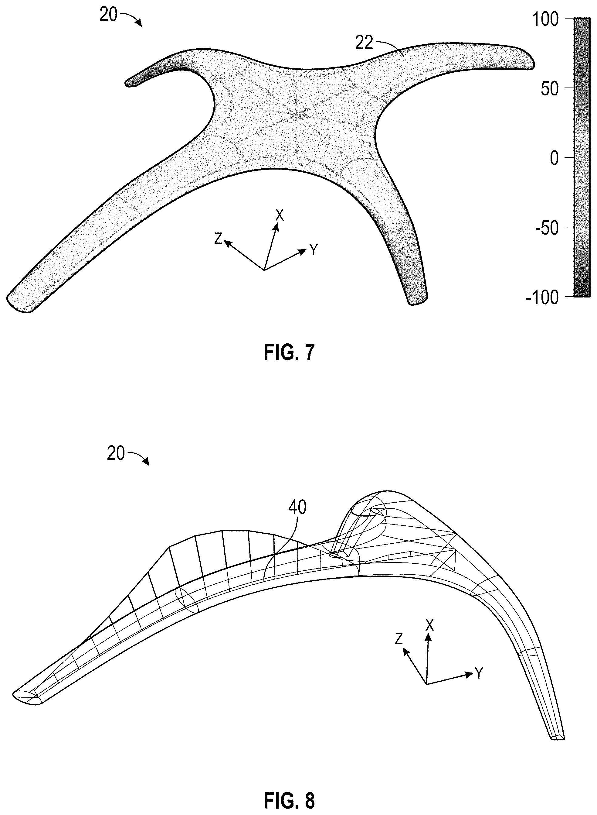
FIG. 7 is a top perspective view of a second embodiment of the support member of the present invention.
FIG. 8 line drawing of a third embodiment of the support member of the present invention.
FIG. 9 is a line drawing of a fourth embodiment of the support member of the present invention.
FIG. 10 is a graph showing the curvature of the spline of the embodiment shown in FIG. 8.
FIG. 11 is a graph showing the derivative of curvature vs. position on spline of the embodiment shown in FIG. 8.
FIG. 12 is a side perspective view of a putter head with shading representing an enclosed volume.
FIG. 13 is a rear perspective view of the putter head shown in FIG. 12 without the enclosed volume shading and incorporating a plurality of support members of the present invention.
FIG. 14 is a side view of the embodiment shown in FIG. 13.
FIG. 15 is a cross-sectional view of the putter head shown in FIG. 13 along lines 15-15.
DETAILED DESCRIPTION OF THE INVENTION
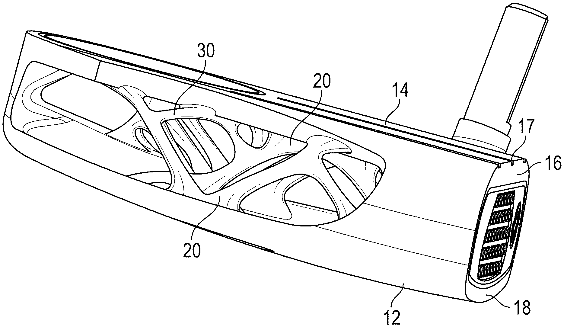
The present invention is directed to a golf club head, and particularly a putter head 10, with improved structural support members 20. The putter head 10 comprises a face 16, a sole portion 12 extending from a lower edge 18 of the face 16, and a top or crown portion 14 extending from an upper edge 17 of the face 16. Though the embodiments herein are directed to a putter head, the novel features disclosed herein may be used in connection with other types of golf club heads, such as drivers, fairway woods, irons, and wedges.
In order to attain an optimized design for the support members 20, the relationship between curvature, rate of change of curvature, spline length, cross-sectional area, and cross-sectional shape of each structure must be examined. By controlling each of these geometric features, support members 20 can be created that are much improved over existing prior art support structures within golf club heads.
The support members 20 of the present invention include networks of slender connected elements, and may also be referred to as rods, beams, or ligaments. Each support member 20 is either connected to another support member 20 or to the surface of another type of structure, such as a sole portion 12 or top or crown portion 14 of the putter head 10. In the preferred embodiment shown in FIG. 13-15, the support members connect the sole portion 12 to the crown portion 14, but in an alternative embodiment, the support members may attach only to a single surface, such as the face 16. Some support members 20 also have at least one connection to another support member 20.
At the connection to another support member 20, the surfaces 22 of the support member 20 have a curvature that changes smoothly and continuously. There are no sharp corners and there are no simple fillets with constant surface curvature.
As shown in FIG. 9, for each support member 20, the equivalent diameter D.sub.E is the diameter of a circle 42 with the same area A as the cross section 44 of the support member 20. The cross section 44 is taken in the plane 46 normal to the spline 40 running through the center of the support member 20 along its length. The support member 20 cross section 44 has an area A, and the equivalent diameter D.sub.E is defined as D.sub.E=(4*A/pi){circumflex over ( )}(1/2).
The length of the spline 40 is no less than three times the equivalent diameter D.sub.E. The equivalent diameter D.sub.E and the cross sectional shape 44 change continuously along the length of each spline 40, but the equivalent diameter D.sub.E is always greater than 0.010'' and always less than 1.000'', more preferably 0.050''-0.500,'' and most preferably 0.050''-0.250''.
As shown in FIGS. 6-9, each spline 40 is curved, and as illustrated in FIGS. 10-11, the curvature continuously changes along the length of the spline 40, with specific ranges of curvature and rates of change of curvature. The entire network of support members 20 occupies a volume 30 that is no greater than 75% of the enveloping volume 50. The enveloping volume 50, which is illustrated in FIG. 12, is the total volume that could be occupied by support members 20 given the application.
The support members 20 disclosed herein are preferably manufactured via 3D printing. In alternative embodiments, the support members 20 may be manufactured via other methods known to a person skilled in the art, such as investment casting, plastic injection molding, compression molding, forging, forming, and metal injection molding.
When compared with prior art structural members, the support members 20 disclosed herein (1) are less susceptible to stress concentrations during the use of the structural part or component, (2) allow for improved flow and reduced porosity in investment casting operations, (3) allow for improved flow and reduced porosity in plastic injection molding, metal injection molding, compression molding, (4) are less susceptible to local stress concentrations and cracking during sintering of metal injection molding or 3D printed parts, and (5) are less susceptible to local stress concentrations and cracking during the build process for laser-based 3D printing methods, like direct metal laser melting (DMLM) or direct metal laser sintering (DMLS). The support members 20 of the present invention also have a unique "organic" appearance that is not found in prior art structural golf club parts.
From the foregoing it is believed that those skilled in the pertinent art will recognize the meritorious advancement of this invention and will readily understand that while the present invention has been described in association with a preferred embodiment thereof, and other embodiments illustrated in the accompanying drawings, numerous changes, modifications and substitutions of equivalents may be made therein without departing from the spirit and scope of this invention which is intended to be unlimited by the foregoing except as may appear in the following appended claims. Therefore, the embodiments of the invention in which an exclusive property or privilege is claimed are defined in the following appended claims.
* * * * *
D00000
D00001
D00002
D00003
D00004
D00005
D00006
D00007
D00008
D00009
XML
uspto.report is an independent third-party trademark research tool that is not affiliated, endorsed, or sponsored by the United States Patent and Trademark Office (USPTO) or any other governmental organization. The information provided by uspto.report is based on publicly available data at the time of writing and is intended for informational purposes only.
While we strive to provide accurate and up-to-date information, we do not guarantee the accuracy, completeness, reliability, or suitability of the information displayed on this site. The use of this site is at your own risk. Any reliance you place on such information is therefore strictly at your own risk.
All official trademark data, including owner information, should be verified by visiting the official USPTO website at www.uspto.gov. This site is not intended to replace professional legal advice and should not be used as a substitute for consulting with a legal professional who is knowledgeable about trademark law.