System for welding
Rajagopalan November 10, 2
U.S. patent number 10,828,715 [Application Number 15/506,818] was granted by the patent office on 2020-11-10 for system for welding. This patent grant is currently assigned to CRC-EVANS PIPELINE INTERNATIONAL, INC.. The grantee listed for this patent is CRC-EVANS PIPELINE INTERNATIONAL INC.. Invention is credited to Shankar Rajagopalan.


View All Diagrams
| United States Patent | 10,828,715 |
| Rajagopalan | November 10, 2020 |
System for welding
Abstract
A welding system includes a welding station having a weld station computer and a weld system in communication with the weld station computer. The weld system includes a supply of weld material, a welding device, and a weld supply motor assembly that moves the weld material to the welder device. The system further includes a weighting device operatively connected with the weld station computer to measure a weight of the supply of weld material and to communicate the weight of the supply of weld material to the weld station computer; and a sensor operatively connected with the weld supply motor assembly and the weld station computer so as to communicate the speed of the weld supply motor assembly to the weld station computer. The weld station computer is operatively connected to the weld supply motor assembly to control the speed of the motor assembly based on the weight data.
| Inventors: | Rajagopalan; Shankar (Cypress, TX) | ||||||||||
|---|---|---|---|---|---|---|---|---|---|---|---|
| Applicant: |
|
||||||||||
| Assignee: | CRC-EVANS PIPELINE INTERNATIONAL,
INC. (Houston, TX) |
||||||||||
| Family ID: | 1000005171411 | ||||||||||
| Appl. No.: | 15/506,818 | ||||||||||
| Filed: | August 28, 2015 | ||||||||||
| PCT Filed: | August 28, 2015 | ||||||||||
| PCT No.: | PCT/US2015/047603 | ||||||||||
| 371(c)(1),(2),(4) Date: | February 27, 2017 | ||||||||||
| PCT Pub. No.: | WO2016/033568 | ||||||||||
| PCT Pub. Date: | March 03, 2016 |
Prior Publication Data
| Document Identifier | Publication Date | |
|---|---|---|
| US 20170274467 A1 | Sep 28, 2017 | |
Related U.S. Patent Documents
| Application Number | Filing Date | Patent Number | Issue Date | ||
|---|---|---|---|---|---|
| 62043757 | Aug 29, 2014 | ||||
| Current U.S. Class: | 1/1 |
| Current CPC Class: | B23K 9/0956 (20130101); B23K 9/0953 (20130101); B23K 9/1087 (20130101); B23K 2101/10 (20180801) |
| Current International Class: | B23K 9/10 (20060101); B23K 9/095 (20060101) |
| Field of Search: | ;219/124.34,125.11,125.12,130.1,130.51,132,137R,137.71,37.72 |
References Cited [Referenced By]
U.S. Patent Documents
| 1693064 | November 1928 | Tipton |
| 1846470 | February 1932 | Burnish |
| 2037962 | April 1936 | Brown |
| 2259367 | October 1941 | Ely et al. |
| 2308340 | January 1943 | Newlon |
| 2400737 | May 1946 | Brown, Jr. |
| 2780194 | February 1957 | Croswell |
| 2816208 | December 1957 | McDowall |
| 2833910 | May 1958 | Stanton et al. |
| 2887972 | May 1959 | Handley |
| 2936517 | May 1960 | Brown, Jr. et al. |
| 3008037 | November 1961 | Harmes |
| 3009048 | November 1961 | Stanley |
| 3009049 | November 1961 | Stanley |
| 3016856 | January 1962 | Cummings |
| 3044431 | July 1962 | Cummings |
| 3110277 | November 1963 | Dixon et al. |
| 3164712 | January 1965 | Paton et al. |
| 3194466 | July 1965 | Davis |
| 3209115 | September 1965 | Van Iperen |
| 3261529 | July 1966 | Pagan |
| 3369725 | February 1968 | Thomas |
| 3379853 | April 1968 | Domizi |
| 3424887 | January 1969 | Fehlman |
| 3461264 | August 1969 | Nelson et al. |
| 3508433 | April 1970 | Bustin |
| 3534199 | October 1970 | Downey et al. |
| 3539915 | November 1970 | Walters et al. |
| 3551636 | December 1970 | Nelson |
| 3561320 | February 1971 | Nelson |
| 3581049 | May 1971 | Creith |
| 3611541 | October 1971 | Garrett |
| 3612808 | October 1971 | Nelson et al. |
| 3633813 | January 1972 | Looney |
| 3645105 | February 1972 | Nolan, Jr. |
| 3646309 | February 1972 | Smith, Jr. et al. |
| 3668359 | June 1972 | Emmerson |
| 3681560 | August 1972 | Stanley |
| 3727025 | April 1973 | Dibenedetto |
| 3741457 | June 1973 | Gwin |
| 3748426 | July 1973 | Stanley |
| 3750451 | August 1973 | Nolan, Jr. |
| 3761005 | September 1973 | Baxter et al. |
| 3764056 | October 1973 | Edwards et al. |
| 3765665 | October 1973 | Work |
| 3806694 | April 1974 | Randolph |
| 3841547 | October 1974 | Bartley |
| 3857162 | December 1974 | Hoffmann |
| 3895209 | July 1975 | Moriki et al. |
| 3904845 | September 1975 | Minkiewicz |
| 3920171 | November 1975 | Clavin |
| 3922517 | November 1975 | Nelson |
| 3961741 | June 1976 | Klein |
| 3974356 | August 1976 | Nelson et al. |
| 3979041 | September 1976 | Kaneyama et al. |
| 3992818 | November 1976 | Clausen |
| 4019016 | April 1977 | Friedman et al. |
| 4039115 | August 1977 | Randolph et al. |
| 4084739 | April 1978 | Koltz |
| 4092950 | June 1978 | Hart |
| 4101067 | July 1978 | Sloan et al. |
| 4144992 | March 1979 | Omae et al. |
| 4145593 | March 1979 | Merrick |
| 4145594 | March 1979 | Koshiga |
| 4152568 | May 1979 | Yamaguchi et al. |
| 4213345 | July 1980 | Dufour |
| 4215809 | August 1980 | Davis |
| 4218604 | August 1980 | Masaoka et al. |
| 4223197 | September 1980 | Imai et al. |
| 4253599 | March 1981 | Slavens |
| 4273985 | June 1981 | Paton et al. |
| 4283617 | August 1981 | Merrick et al. |
| 4285460 | August 1981 | Clavin |
| 4306134 | December 1981 | Slavens |
| 4310737 | January 1982 | Paton |
| 4340163 | July 1982 | Romashov |
| 4360961 | November 1982 | Chlebowski |
| 4380696 | April 1983 | Masaki |
| 4436974 | March 1984 | Lebedev |
| 4443677 | April 1984 | DeSaw |
| 4483106 | November 1984 | Wachs et al. |
| 4491718 | January 1985 | Cook et al. |
| 4500764 | February 1985 | Girodi |
| 4504047 | March 1985 | Jantzen |
| 4531192 | July 1985 | Cook |
| 4565003 | January 1986 | McLeod |
| 4573666 | March 1986 | Nomura et al. |
| 4575611 | March 1986 | Bertossa |
| 4582241 | April 1986 | Johnson |
| 4638984 | January 1987 | Puisais et al. |
| 4666138 | May 1987 | Dearman |
| 4667936 | May 1987 | Hale, Jr. |
| 4712720 | December 1987 | Tesch |
| 4715809 | December 1987 | Langhoff et al. |
| 4750662 | June 1988 | Kagimoto |
| 4831233 | May 1989 | Gordon |
| 4838477 | June 1989 | Roach et al. |
| 4839495 | June 1989 | Kitera et al. |
| 4851639 | July 1989 | Sugitani |
| 4927091 | May 1990 | Weiss et al. |
| 4959523 | September 1990 | Fihey et al. |
| 5097110 | March 1992 | Hamada et al. |
| 5107387 | April 1992 | Orton |
| 5136452 | August 1992 | Orton |
| 5148000 | September 1992 | Tews |
| 5165160 | November 1992 | Poncelet |
| 5227601 | July 1993 | Black |
| 5235152 | August 1993 | Jankus |
| 5288005 | February 1994 | Beakley |
| 5288963 | February 1994 | Jusionis |
| 5343016 | August 1994 | Davis et al. |
| 5435478 | July 1995 | Wood et al. |
| 5435479 | July 1995 | Puzey et al. |
| 5474225 | December 1995 | Geier et al. |
| 5481085 | January 1996 | Kovacevic et al. |
| 5593605 | January 1997 | Jones |
| 5601225 | February 1997 | Wood et al. |
| 5667706 | September 1997 | Pirl |
| 5669547 | September 1997 | Spring |
| 5685996 | November 1997 | Ricci |
| 5685999 | November 1997 | Wiedemann et al. |
| 5706863 | January 1998 | Matherne et al. |
| 5728992 | March 1998 | Swidwa |
| 5738725 | April 1998 | Bernstein, Jr. |
| 5796069 | August 1998 | Jones et al. |
| 5816479 | October 1998 | Matherne et al. |
| 5837966 | November 1998 | Timmons, Jr. |
| 5865430 | February 1999 | Conover et al. |
| 5925268 | July 1999 | Britnell |
| 6022506 | February 2000 | Simmons |
| 6027007 | February 2000 | Bosio |
| 6044769 | April 2000 | Oka et al. |
| 6051803 | April 2000 | Hale, Jr. |
| 6075220 | June 2000 | Essien et al. |
| 6084203 | July 2000 | Bonigen |
| 6098866 | August 2000 | Tsuchiya et al. |
| 6109503 | August 2000 | Parker |
| 6188041 | February 2001 | Kim et al. |
| 6220498 | April 2001 | Gordon et al. |
| 6230072 | May 2001 | Powell et al. |
| 6290786 | September 2001 | Brown et al. |
| 6325277 | December 2001 | Collie |
| 6333699 | December 2001 | Zierolf |
| 6417488 | July 2002 | Takeuchi et al. |
| 6515251 | February 2003 | Wind |
| 6583386 | June 2003 | Ivkovich |
| 6596961 | July 2003 | Ehlers et al. |
| 6605800 | August 2003 | Schick et al. |
| 6752175 | June 2004 | Willschuetz et al. |
| 6759968 | July 2004 | Zierolf |
| 6840433 | January 2005 | Vermaat |
| 6850161 | February 2005 | Elliott et al. |
| 6909066 | June 2005 | Zheng et al. |
| 6917176 | July 2005 | Schempf et al. |
| 6924452 | August 2005 | Kimura |
| 6926069 | August 2005 | Roffelsen |
| 7014100 | March 2006 | Zierolf |
| 7032809 | April 2006 | Hopkins |
| 7091447 | August 2006 | Kim et al. |
| 7114881 | October 2006 | Belloni et al. |
| 7159654 | January 2007 | Ellison et al. |
| 7182025 | February 2007 | Ghorbel et al. |
| 7205503 | April 2007 | Reynolds et al. |
| 7277014 | October 2007 | Waterhouse et al. |
| 7282663 | October 2007 | Alford et al. |
| 7474221 | January 2009 | Den Boer et al. |
| 7484625 | February 2009 | Scott et al. |
| 7510218 | March 2009 | Holdren |
| 7540401 | June 2009 | Vermaat |
| 7577285 | August 2009 | Schwarz et al. |
| 7657082 | February 2010 | Kubo et al. |
| 7661574 | February 2010 | McGushion |
| 7675422 | March 2010 | Stevens et al. |
| 7677439 | March 2010 | Zierolf |
| 7688210 | March 2010 | Staff |
| 7713000 | May 2010 | Verkuijl et al. |
| 7774917 | August 2010 | Anderson et al. |
| 7780065 | August 2010 | Vermaat |
| 7798023 | September 2010 | Hoyt et al. |
| 7802714 | September 2010 | Kuchuk-Yatsenko et al. |
| 7915561 | March 2011 | Kossowan |
| 7966860 | June 2011 | Dijkstra |
| 8016037 | September 2011 | Bloom et al. |
| 8091775 | January 2012 | Zierolf |
| 8115138 | February 2012 | Jacovetty et al. |
| 8205503 | June 2012 | Cox |
| 8313016 | November 2012 | Dagenais |
| 8328071 | December 2012 | Lavalley et al. |
| 8350184 | January 2013 | Behr et al. |
| 8353443 | January 2013 | Sugiyama et al. |
| 8378841 | February 2013 | Stevens et al. |
| 8389902 | March 2013 | McKinley |
| 8534530 | September 2013 | Biggs |
| 8590769 | November 2013 | Lavalley et al. |
| 8658941 | February 2014 | Albrecht |
| 8689836 | April 2014 | Hudson |
| 8695198 | April 2014 | Dagenais |
| 8714433 | May 2014 | Snead et al. |
| 8777201 | July 2014 | Dagenais |
| 8777482 | July 2014 | Pfitzner et al. |
| 8782863 | July 2014 | Pfeiffer |
| 8800575 | August 2014 | Angel |
| 8864012 | October 2014 | Bonelli |
| 8955733 | February 2015 | Vanderpol et al. |
| 8973244 | March 2015 | Lavalley et al. |
| 9030324 | May 2015 | Christiansen et al. |
| 9038670 | May 2015 | Vinoy |
| 9183222 | November 2015 | Gale et al. |
| 9304204 | April 2016 | Krauhausen et al. |
| 9821415 | November 2017 | Rajagopalan |
| 2001/0015349 | August 2001 | Belloni |
| 2001/0017292 | August 2001 | Belloni |
| 2003/0188589 | October 2003 | Harthorn et al. |
| 2004/0009042 | January 2004 | Belloni et al. |
| 2004/0032597 | February 2004 | Esmiller |
| 2004/0099713 | May 2004 | Laing |
| 2005/0103766 | May 2005 | Iizuka et al. |
| 2005/0247686 | November 2005 | Child |
| 2006/0070987 | April 2006 | Daniel |
| 2007/0000972 | January 2007 | Koga |
| 2007/0023185 | February 2007 | Hall et al. |
| 2007/0023479 | February 2007 | Koppert |
| 2007/0145129 | June 2007 | Perkin et al. |
| 2007/0210047 | September 2007 | Child |
| 2007/0256288 | November 2007 | Vermaat |
| 2009/0019783 | January 2009 | Amano |
| 2009/0078742 | March 2009 | Pasquali |
| 2009/0212024 | August 2009 | Muller et al. |
| 2009/0230120 | September 2009 | Yang |
| 2009/0307891 | December 2009 | Offer |
| 2010/0051672 | March 2010 | Nunnery |
| 2010/0126968 | May 2010 | Page |
| 2010/0230953 | September 2010 | Baylot et al. |
| 2011/0107571 | May 2011 | Kerdiles |
| 2011/0192569 | August 2011 | McKinley |
| 2011/0198316 | August 2011 | Legori et al. |
| 2011/0297316 | December 2011 | Jackson et al. |
| 2012/0061452 | March 2012 | Wolstenholme |
| 2012/0074631 | March 2012 | Dagenais |
| 2012/0126008 | May 2012 | Binmore |
| 2012/0174372 | July 2012 | Dagenais |
| 2012/0187096 | July 2012 | Schmid et al. |
| 2012/0201348 | August 2012 | Knight et al. |
| 2012/0213937 | August 2012 | Lavalley et al. |
| 2012/0215354 | August 2012 | Krasny et al. |
| 2012/0257042 | October 2012 | McKaigue et al. |
| 2012/0297652 | November 2012 | Halvorsen |
| 2013/0008548 | January 2013 | Bowers |
| 2013/0026148 | January 2013 | Aoyama et al. |
| 2013/0048619 | February 2013 | Doyle et al. |
| 2013/0075380 | March 2013 | Albrech |
| 2013/0112677 | May 2013 | Christopher et al. |
| 2013/0119037 | May 2013 | Daniel |
| 2013/0126497 | May 2013 | Miller |
| 2013/0126503 | May 2013 | McKinley |
| 2013/0200057 | August 2013 | Miller |
| 2013/0306710 | November 2013 | Kim |
| 2014/0001166 | January 2014 | Peters et al. |
| 2014/0006227 | January 2014 | Griggs et al. |
| 2014/0042207 | February 2014 | Lavalley et al. |
| 2014/0091129 | April 2014 | Peters et al. |
| 2014/0107947 | April 2014 | Papadimitriou et al. |
| 2014/0131333 | May 2014 | Zhang |
| 2014/0137389 | May 2014 | Dagenais |
| 2014/0191904 | July 2014 | Illerhaus |
| 2014/0217154 | August 2014 | Obaditch |
| 2014/0266009 | September 2014 | Comello et al. |
| 2014/0294285 | October 2014 | Duckworth et al. |
| 2014/0346163 | November 2014 | Rajagopalan et al. |
| 2015/0034629 | February 2015 | Sherrill et al. |
| 2015/0083785 | March 2015 | Park |
| 2015/0108223 | April 2015 | Weitzhandler |
| 2015/0114507 | April 2015 | Warren |
| 2015/0129579 | May 2015 | Traver |
| 2015/0146216 | May 2015 | Krauhausen et al. |
| 2015/0226872 | August 2015 | Doany et al. |
| 2015/0248569 | September 2015 | Rushing |
| 2015/0273636 | October 2015 | Rajagopalan et al. |
| 2015/0298238 | October 2015 | Van Rensburg |
| 2015/0330551 | November 2015 | Van Nie et al. |
| 2015/0352653 | December 2015 | Albrecht |
| 2015/0360332 | December 2015 | Singh et al. |
| 2016/0032707 | February 2016 | Bowman |
| 2016/0032713 | February 2016 | Hallundb.ae butted.k et al. |
| 2016/0114418 | April 2016 | Jones |
| 2016/0221107 | August 2016 | Kadlec |
| 2016/0256961 | September 2016 | Clemmons |
| 2017/0144256 | May 2017 | Tao |
| 2017/0182605 | June 2017 | Rajagopalan et al. |
| 2018/0001422 | January 2018 | Rajagopalan et al. |
| 2018/0029154 | February 2018 | Rajagopalan et al. |
| 2018/0031152 | February 2018 | Rajagopalan et al. |
| 2018/0117718 | May 2018 | Rajagopalan et al. |
| 2018/0185951 | July 2018 | Lanz |
| 2019/0176260 | June 2019 | Kadlec |
| 1051979 | Apr 1979 | CA | |||
| 1239448 | Jul 1988 | CA | |||
| 2141524 | Aug 1995 | CA | |||
| 2721167 | Oct 2009 | CA | |||
| 2838608 | Dec 2012 | CA | |||
| 1069213 | Feb 1993 | CN | |||
| 2825214 | Oct 2006 | CN | |||
| 101332550 | Dec 2008 | CN | |||
| 201273837 | Jul 2009 | CN | |||
| 202188887 | Apr 2012 | CN | |||
| 103495795 | Jan 2014 | CN | |||
| 103826788 | May 2014 | CN | |||
| 104010756 | Aug 2014 | CN | |||
| 104209626 | Dec 2014 | CN | |||
| 105675097 | Jun 2016 | CN | |||
| 20 2006 004122 | May 2006 | DE | |||
| 0 193 812 | Sep 1986 | EP | |||
| 0300458 | Jan 1989 | EP | |||
| 1985405 | Oct 2008 | EP | |||
| 2 340 908 | Jul 2011 | EP | |||
| 3106951 | Dec 2016 | EP | |||
| 1 261 814 | Jan 1972 | GB | |||
| 1283922 | Aug 1972 | GB | |||
| 1 386 926 | Mar 1975 | GB | |||
| 2 214 118 | Aug 1989 | GB | |||
| 53113736 | Oct 1978 | JP | |||
| 55027422 | Feb 1980 | JP | |||
| 55040040 | Mar 1980 | JP | |||
| 55156695 | Dec 1980 | JP | |||
| 56148475 | Nov 1981 | JP | |||
| 58145394 | Aug 1983 | JP | |||
| 58-212890 | Dec 1983 | JP | |||
| 59-030495 | Feb 1984 | JP | |||
| 59-92194 | May 1984 | JP | |||
| 59110476 | Jun 1984 | JP | |||
| 60-72673 | Apr 1985 | JP | |||
| 60-82284 | May 1985 | JP | |||
| S61159275 | Jul 1986 | JP | |||
| 01224167 | Sep 1989 | JP | |||
| 02104474 | Apr 1990 | JP | |||
| 2-127976 | May 1990 | JP | |||
| 3-13270 | Jan 1991 | JP | |||
| 3-90282 | Apr 1991 | JP | |||
| 3-90283 | Apr 1991 | JP | |||
| 05000374 | Jan 1993 | JP | |||
| 05069131 | Mar 1993 | JP | |||
| 7-116842 | May 1995 | JP | |||
| 7-155949 | Jun 1995 | JP | |||
| 10-244367 | Sep 1998 | JP | |||
| 11-10486 | Jan 1999 | JP | |||
| 2001-170784 | Jun 2001 | JP | |||
| 2007-205941 | Aug 2007 | JP | |||
| 2008212994 | Sep 2008 | JP | |||
| 2011177016 | Sep 2011 | JP | |||
| 2012-218031 | Nov 2012 | JP | |||
| 20050040883 | May 2005 | KR | |||
| 10-0598523 | Jul 2006 | KR | |||
| 10-2012-0044131 | May 2012 | KR | |||
| 10-1143532 | May 2012 | KR | |||
| 2218251 | Dec 2003 | RU | |||
| 1199544 | Dec 1985 | SU | |||
| 1741999 | Jun 1992 | SU | |||
| 8705840 | Oct 1987 | WO | |||
| 90/06205 | Jun 1990 | WO | |||
| 9705983 | Feb 1997 | WO | |||
| 00/41843 | Jul 2000 | WO | |||
| 0041488 | Jul 2000 | WO | |||
| 0041845 | Jul 2000 | WO | |||
| 01/70446 | Sep 2001 | WO | |||
| 02/00385 | Jan 2002 | WO | |||
| 0249799 | Jun 2002 | WO | |||
| 2007/097589 | Aug 2007 | WO | |||
| 2009/059776 | May 2009 | WO | |||
| 2010/002269 | Jan 2010 | WO | |||
| 2010/046390 | Apr 2010 | WO | |||
| 2011/012998 | Feb 2011 | WO | |||
| 2013/171589 | Nov 2013 | WO | |||
| 2013172244 | Nov 2013 | WO | |||
| 2015/148765 | Oct 2015 | WO | |||
| 2016/153562 | Sep 2016 | WO | |||
Other References
|
Notice of Allowance issued in corresponding U.S. Appl. No. 15/441,804, dated Jul. 3, 2019. cited by applicant . Non-Final Office Action issued in corresponding U.S. Appl. No. 15/714,117, dated Jun. 19, 2019. cited by applicant . Official Action issued in corresponding Mexican Patent Application No. MX/a/2017/002690, dated May 7, 2019. cited by applicant . Decision to Grant issued in corresponding Russian Patent Application No. 2015154971, dated Apr. 22, 2019. cited by applicant . Office Action issued for corresponding Russian Patent Application No. 2017134991/02(061281), dated May 29, 2019. cited by applicant . Technical Examination Report issued for corresponding Brazilian Patent Application No. BR112015029273-9, dated Jun. 20, 2019. cited by applicant . Notice of Acceptance issued for corresponding Australian Patent Applioation No. 2015236037, dated Jul. 19, 2019. cited by applicant . International Preliminary Report on Patentability issued for corresponding International Application No. PCT/US2017/042612, dated Jul. 30, 2019. cited by applicant . Examination Report issued for corresponding European Patent Application No. 15836899.3, dated Aug. 8, 2019. cited by applicant . "Explorer II--Wireless Self-powered Visual and NDE Robotic Inspection System for Live Gas Pipelines", National Energy Technology Laboratory, DE-FC26-04NT42264, downloaded from URL: http://www.netl.doe.gov/research/oil-and-gas/project-summaries/completed-- td/de-fc26-04nt42264 (4 pages). cited by applicant . "Final Report: Explorer-II: Wireless Self-powered Visual and NDE Robotic Inspection System for Live Gas Distribution Mains", Oil & Natrural Gas Technology,DE-FC26-04NT-42264, downloaded from URL: https://www.netl.doe.gov/File%20Library/Research/Oil-Gas/NT42264_FinalRep- ort.pdf (120 pages). cited by applicant . Non-Final Office Action dated Aug. 11, 2016 in corresponding U.S. Appl. No. 14/272,914. cited by applicant . International Search Report dated Jul. 23, 2015 in corresponding International Patent Application No. PCT/US2015/022665. cited by applicant . Final Office Action issued in corresponding U.S. Appl. No. 14/272,914 dated Jan. 26, 2017. cited by applicant . International Search Report and the Written Opinion of the International Searching Authority dated Mar. 29, 2016 in corresponding International Application No. PCT/US2015/062558 (46 pages). cited by applicant . Non-Final Office Action issued in corresponding U.S. Appl. No. 14/228,708, dated Mar. 1, 2017. cited by applicant . Extended European Search Report, including Search Opinion, issued in corresponding European Patent Application No. 14800710.7, dated Jan. 23, 2017. cited by applicant . Non-Final Office Action dated Jun. 20, 2016 in corresponding U.S. Appl. No. 14/228,708 (12 pages). cited by applicant . International Search Report and Written Opinion issued for corresponding International Patent Application No. PCT/US2015/022665, dated Jul. 23, 2015 (11 pages). cited by applicant . International Preliminary Report on Patentability issued for corresponding International Patent Application No. PCT/US2015/022665, dated Oct. 13, 2016 (10 pages). cited by applicant . Examination Report issued for corresponding Australian Patent Application No. 2014268528, dated Apr. 28, 2017. cited by applicant . Examination Report issued for corresponding Chinese Patent Application No. 201480029722.8, dated May 15, 2017. cited by applicant . Examination Report issued for corresponding Chinese Patent Application No. 201480029722.8, dated Jul. 18, 2016. cited by applicant . Search Report and Written Opinion issued for corresponding International Application No. PCT/US2014/039148, dated Oct. 1, 2014. cited by applicant . International Preliminary Report on Patentability issued for corresponding International Application No. PCT/US2014/039148, dated Dec. 3, 2015. cited by applicant . International Preliminary Report on Patentability issued in corresponding International Patent Application No. PCT/US2015/047603, dated Mar. 9, 2017. cited by applicant . Examination Report issued for corresponding European Patent Application No. 14800710.7, dated Feb. 7, 2019. cited by applicant . Office Action issued in corresponding Chinese Patent Application No. 201580016820.2, dated Apr. 4, 2018. cited by applicant . Office Action issued in corresponding Chinese Patent Application No. 201580045390.7, dated Apr. 10, 2018. cited by applicant . Office Action and Search Report issued in corresponding Russian Patent Application No. 2015154971, dated Apr. 27, 2018. cited by applicant . Examination Report issued for corresponding Chinese Patent Application No. 201480029722.8, dated Apr. 4, 2018. cited by applicant . European Search Report issued for corresponding European Patent Application No. 15836899.3, dated May 24, 2018. cited by applicant . International Search Report and Written Opinion of International Patent Application No. PCT/US2015/047603, dated Jan. 5, 2016. cited by applicant . Search Report and Written Opinion issued for corresponding International Application No. PCT/US2017/042612, dated Nov. 13, 2017. cited by applicant . Search Report and Written Opinion issued for corresponding International Application No. PCT/IB2017/055221, dated Nov. 30, 2017. cited by applicant . Second Office Action issued in corresponding Chinese Patent Application No. 201580080511.1, dated Aug. 26, 2019. cited by applicant . Decision to Grant issued in corresponding Russian Patent Application No. 2017134991, dated Aug. 29, 2019. cited by applicant . Third Office Action issued in corresponding Chinese Patent Application No. 201580045390.7, dated Sep. 20, 2019. cited by applicant . Preliminary Office Action Report issued in corresponding Brazilian Patent Application No. BR112017020431-2, dated Oct. 1, 2019. cited by applicant . Notice of Allowance issued in corresponding U.S. Appl. No. 15/714,117, dated Oct. 28, 2019. cited by applicant . Non-Final Office Action issued in corresponding U.S. Appl. No. 14/272,914, dated Aug. 24, 2017. cited by applicant . Notice of Allowance issued in corresponding U.S. Appl. No. 14/228,708, dated Jul. 17, 2017. cited by applicant . Office Action issued in corresponding Chinese Patent Application No. 201580016820.2, dated Jul. 19, 2017. cited by applicant . International Preliminary Report on Patentability issued for corresponding International Patent Application No. PCT/US2015/062558, dated Oct. 5, 2017. cited by applicant . Non-Final Office Action issued in corresponding U.S. Appl. No. 15/441,804, dated Jul. 30, 2018. cited by applicant . Non-Final Office Action issued in corresponding U.S. Appl. No. 15/714,117, dated Sep. 17, 2018. cited by applicant . Extended Search Report issued for corresponding European Patent Application No. 15886707.7, dated Nov. 13, 2018. cited by applicant . Office Action issued in corresponding Russian Patent Application No. 2016142270/06(067667), dated Nov. 15, 2018. cited by applicant . Office Action issued in corresponding Chinese Patent Application No. 201580080511.1, dated Dec. 3, 2018. cited by applicant . Examination Report issued for corresponding Australian Patent Application No. 2015236037, dated Jan. 4, 2019. cited by applicant . Final Office Action issued in corresponding U.S. Appl. No. 15/441,804, dated Jan. 23, 2019. cited by applicant . Final Office Action issued in corresponding U.S. Appl. No. 14/272,914 dated Jan. 25, 2018. cited by applicant . Notice of Allowance issued in corresponding U.S. Appl. No. 14/272,914, dated Apr. 6, 2018. cited by applicant . Decision to Grant issued in corresponding Russian Patent Application No. 2016142270, dated Feb. 12, 2019. cited by applicant . Official Action issued in corresponding Russian Patent Application No. 2017110223, dated Jan. 31, 2019. cited by applicant . Official Action issued in corresponding Malaysian Patent Application No. PI2015704216, dated Mar. 29, 2019. cited by applicant . Second Office Action issued in corresponding Chinese Patent Application No. 201580045390.7, dated Mar. 4, 2019. cited by applicant . Final Office Action issued in corresponding U.S. Appl. No. 15/714,117, dated Feb. 15, 2019. cited by applicant . Extended European Search Report, including Search Opinion, issued in corresponding European Patent Application No. 15768987.8, dated Oct. 20, 2017. cited by applicant . Non-Final Office Action issued in corresponding U.S. Appl. No. 15/632,061, dated Jan. 27, 2020. cited by applicant . Preliminary Office Action issued in corresponding Brazilian Patent Application No. 112016022229-6, dated Jan. 14, 2020. cited by applicant . Notice of Allowance issued in corresponding U.S. Appl. No. 15/560,954, dated Feb. 13, 2020. cited by applicant . Third Office Action issued in corresponding Chinese Patent Application No. 201580080511.1, dated Mar. 3, 2020. cited by applicant . Office Action issued in corresponding Canadian Patent Application No. 2,942,368, dated Apr. 2, 2020. cited by applicant . "Effects of Welding Point Position, Inclination, Roll Angle and Welding Speed of Submerged Arc of Spiral Steel Pipe on Welding Quality", Liu Baoqiang, National Steel Rolling Production Technology Conference, pp. 919-922, Dec. 31, 2008. (relevance found on pp. 6 and 14 of the Decision of Rejection issued in corresponding Chinese Patent Application No. 201580080511.1, dated Aug. 19, 2020). cited by applicant . "Droplet Transition and Process Characteristics of Double Wire Pulse MAG Welding", Yu Lu et al., Welding Journal, Oct. 31, 2012. (relevance found on pp. 6 and 14 of the Decision of Rejection issued in corresponding Chinese Patent Application No. 201580080511.1, dated Aug. 19, 2020). cited by applicant . "Effects of Laser-MIG Hybrid Welding Process Parameters of Q345 Steel on Weld Joint Formation", Yin Jie, Engineering Machinery, Aug. 31, 2013. (relevance found on pp. 6 and 14 of the Decision of Rejection issued in corresponding Chinese Patent Application No. 201580080511.1, dated Aug. 19, 2020). cited by applicant . "Welding Handbook", Welding Society of China Mechanical Engineering Society, Mechanical Engineering Press, vol. 1 3rd edition, pp. 64-65, Mar. 31, 2008. (relevance found on pp. 6-7 of the Decision of Rejection issued in corresponding Chinese Patent Application No. 201580080511.1 , dated Aug. 19, 2020). cited by applicant . Decision of Rejection issued in corresponding Chinese Patent Application No. 201580080511.1, dated Aug. 19, 2020. cited by applicant . Fourth Office Action issued in corresponding Chinese Patent Application No. 2015800453907.7, dated May 26, 2020. cited by applicant . Preliminary Office Action issued in corresponding Brazilian Patent Application No. BR112017003933-8, dated Jun. 2, 2020. cited by applicant . Examination Report issued in corresponding Australian Patent Application No. 2015387441, dated Jun. 9, 2020. cited by applicant . Final Office Action issued in corresponding U.S. Appl. No. 15/632,061, dated Jun. 12, 2020. cited by applicant . Examination Report issued in corresponding Australian Patent Application No. 2015308646, dated Jul. 21, 2020. cited by applicant. |
Primary Examiner: Nguyen; Phuong T
Attorney, Agent or Firm: Pillsbury Winthrop Shaw Pittman LLP
Parent Case Text
CROSS REFERENCE TO RELATED APPLICATIONS
The present patent application is the U.S. National Phase entry of International Patent Application No. PCT/US2015/047603, filed Aug. 28, 2015, which claims the benefit of U.S. Provisional Patent Application No. 62/043,757, filed on Aug. 29, 2014, the contents of both applications are incorporated herein by reference in their entirety.
Claims
What is claimed:
1. A welding system, comprising: a plurality of welding stations, each welding station including a weld station computer and weld system in communication with the weld station computer, each welding station including one or more sensors, the one or more sensors configured to measure weld data, wherein the weld data includes data related to one or more operating parameters of the weld system that are configured to control an ongoing weld operation of the weld system; a plurality of wireless devices in communication with the one or more of the welding station computers to receive the weld data; and a cloud server in communication with the wireless devices, the cloud server being configured to process the weld data, wherein the cloud server is configured to communicate the processed weld data to one or more of the wireless devices, wherein, if the weld data is outside a threshold, the weld station computer is configured to instruct the weld system to modify the ongoing weld operation of the weld system.
2. The welding system according to claim 1, wherein the weld data comprises voltage data, current data, speed data, or any proper combination thereof.
3. The welding system according to claim 2, wherein the voltage data includes a lead voltage applied to a weld wire.
4. The welding system according to claim 2, the current data includes a lead current applied to a weld wire.
5. The welding system according to claim 2, wherein, if the current data in the weld system is high, the weld station computer instructs the weld system to slow down a speed of the weld system or controls a position of a torch in the weld system.
6. The welding system according to claim 2, wherein the speed data includes a lead wire speed of a weld wire.
7. The welding system of claim 1, wherein the cloud server is configured to process the weld data in real-time.
8. The welding system according to claim 1, wherein the welding system is configured to provide real-time quality control of the weld operation of the weld system based on the weld data.
9. The welding system according to claim 1, wherein the welding system is configured to provide real-time monitoring the weld operation of the weld system.
10. The welding system according to claim 1, wherein the welding system is configured to process the weld data from one or more of the plurality of welding stations simultaneously.
Description
FIELD OF THE INVENTION
The present patent application pertains to systems and methods for welding.
BACKGROUND OF THE INVENTION
Currently pipe joining technology remains an art relying on the avoidance of error by a worker applying a weld. Current welding technology lacks adequate data management, work control and supervision of activities. As a result of such deficiencies, welding currently suffers from unpredictable quality, undesired variations of methods and techniques, waste of materials, poor economics per weld and safety challenges. The consequences of the currently inadequate welding technologies include, but are not limited to, excessive rework of failed or low quality welds, lack of predictability in weld characteristics, unrepeatable weld procedures, high inspection costs, significant lost time and schedule delays.
SUMMARY OF THE INVENTION
An aspect of an embodiment of the present disclosure is to provide a welding system including a plurality of welding stations, each weld station including a weld station computer and weld system in communication with the weld station computer, each welding station including one or more sensors, the one or more sensors configured to measure weld data including lead wire speed data; a plurality of wireless devices in communication with the one or more of the welding station computers to receive the weld data including the measured lead wire speed data; and a cloud server in communication with the wireless devices, the cloud server being configured to process the weld data including the lead wire speed data, and configured to determine an amount of consumable welding material used by the plurality of welding stations for a given period of time, wherein the cloud server is configured to communicate the amount of consumable welding material used to one or more of the wireless devices.
Another aspect of an embodiment of the present disclosure is to provide a welding system including a welding station, the welding station including a weld station computer and a weld system in communication with the weld station computer, the weld system including a supply of weld material, a welding device, and a weld supply motor assembly that moves the weld material to the welder device; a weighting device operatively connected with the weld station computer and configured to measure a weight of the supply of weld material and to communicate the weight of the supply of weld material to the weld station computer in the form of weight data; and a sensor operatively connected with the weld supply motor assembly and the weld station computer so as to communicate the speed of the weld supply motor assembly to the weld station computer in the form of speed data. The weld station computer is operatively connected to the weld supply motor assembly and is configured to control the speed of the motor assembly based on the weight data.
These and other objects, features, and characteristics of the present disclosure, as well as the methods of operation and functions of the related elements of structure and the combination of parts and economies of manufacture, will become more apparent upon consideration of the following description and the appended claims with reference to the accompanying drawings, all of which form a part of this specification, wherein like reference numerals designate corresponding parts in the various figures. In one embodiment of the invention, the structural components illustrated herein are drawn to scale. It is to be expressly understood, however, that the drawings are for the purpose of illustration and description only and are not intended as a definition of the limits of the invention. As used in the specification and in the claims, the singular form of "a", "an", and "the" include plural referents unless the context clearly dictates otherwise.
BRIEF DESCRIPTION OF THE DRAWINGS
The present invention in its several aspects and embodiments solves the problems discussed above and significantly advances the technology of welding, pipe handling, coating, pipeline construction, construction, management and inspection technologies. The present invention can become more fully understood from the detailed description and the accompanying drawings, wherein:
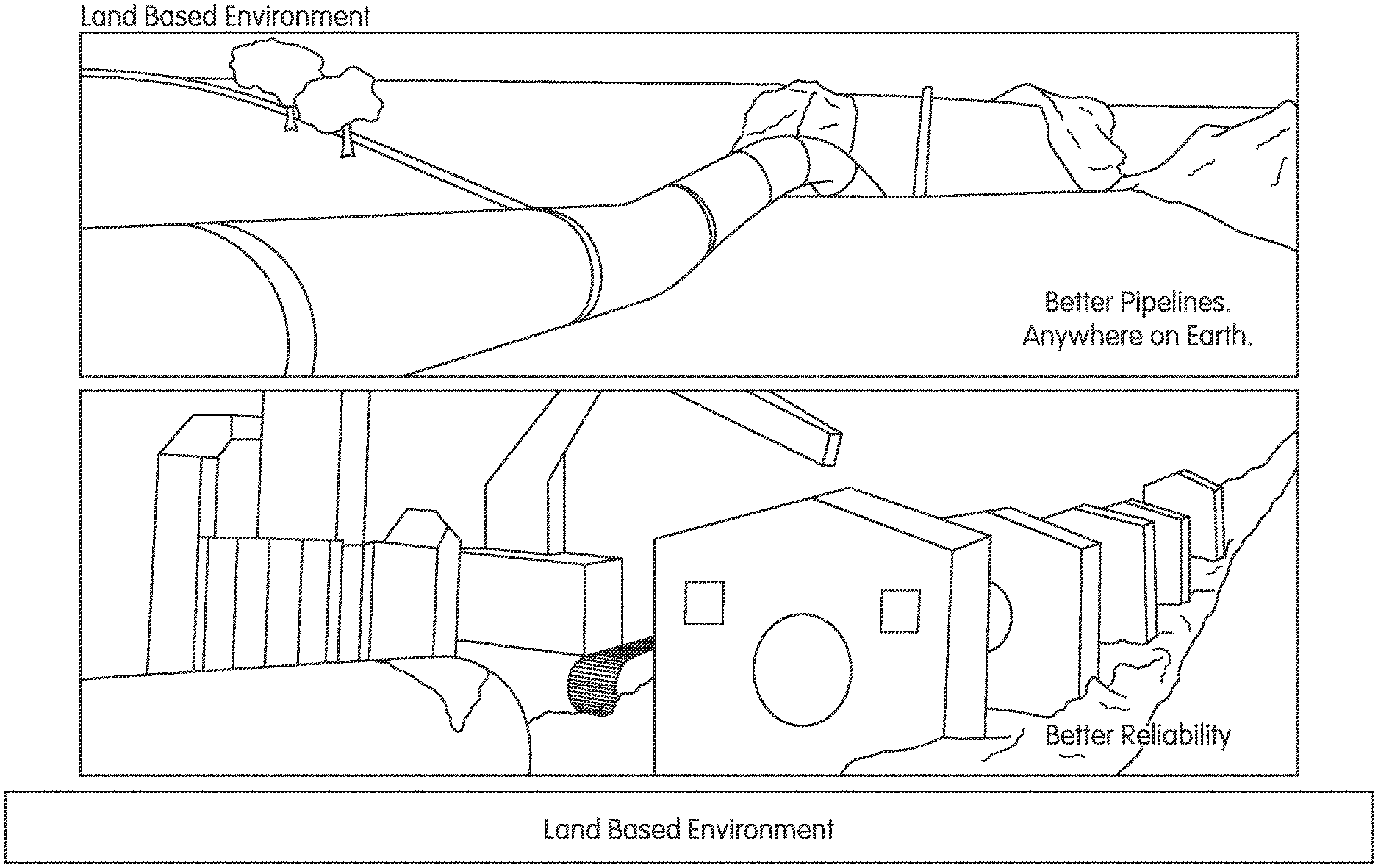
FIG. 1 depict an example of a pipeline;
FIG. 2 shows a welding station, according to an embodiment of the present disclosure;
FIG. 3 show a plurality of pipeline welding stations, according to an embodiment of the present disclosure;
FIG. 4 is a schematic diagram of a system with a plurality of welding stations in communication with a plurality of control and log collection stations, according to an embodiment of the present disclosure;
FIG. 5 is a schematic diagram of a system with a plurality of welding stations in communication with a plurality of control and log collection stations, according to another embodiment of the present disclosure;
FIG. 6 is a schematic diagram of welding station in communication with a network via a WiFi connection, according to an embodiment of the present disclosure;
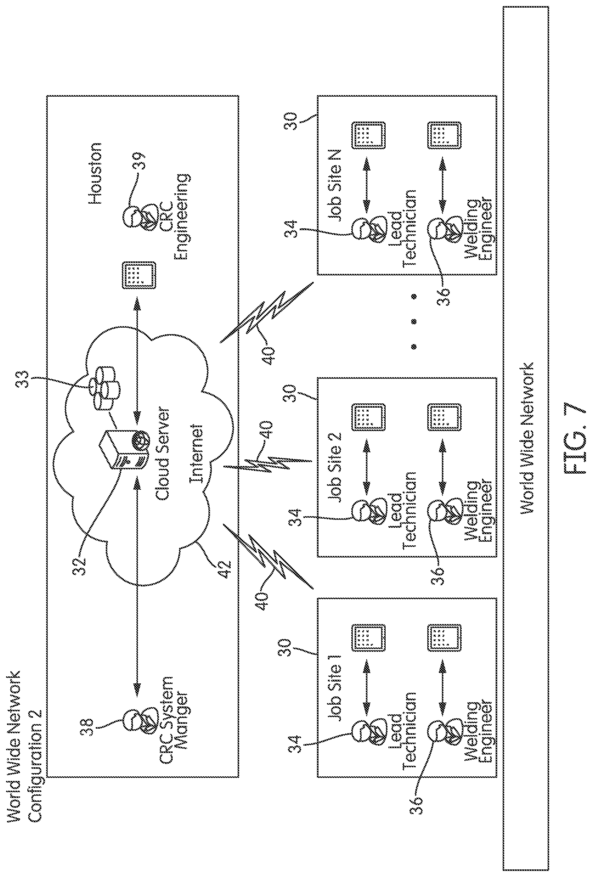
FIG. 7 is a schematic diagram of a plurality of job sites in communication with a cloud server via a worldwide network (internet), according to an embodiment of the present disclosure;
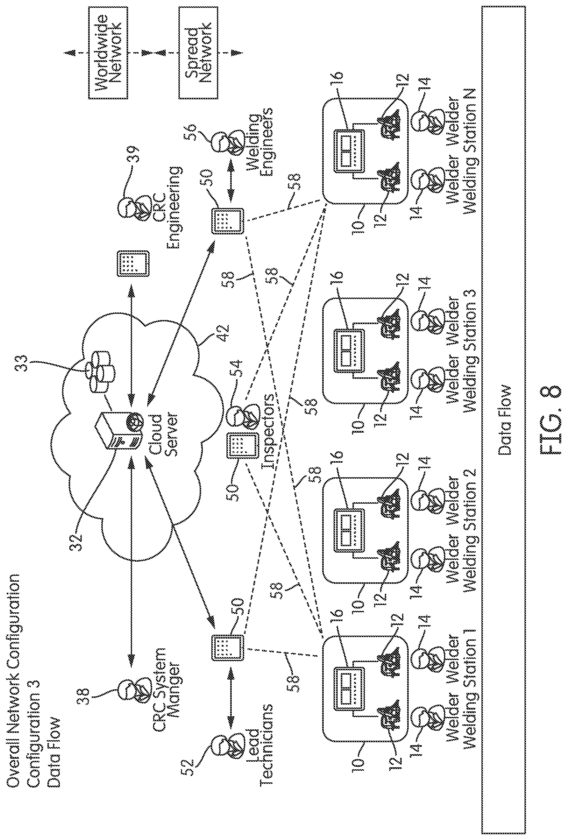
FIG. 8 is a schematic diagram of a plurality of welding stations in communication with intermediate computing devices (lead technicians, inspectors, engineers, etc.) which are in turn in communication with a cloud server through the internet, according to an embodiment of the present disclosure;
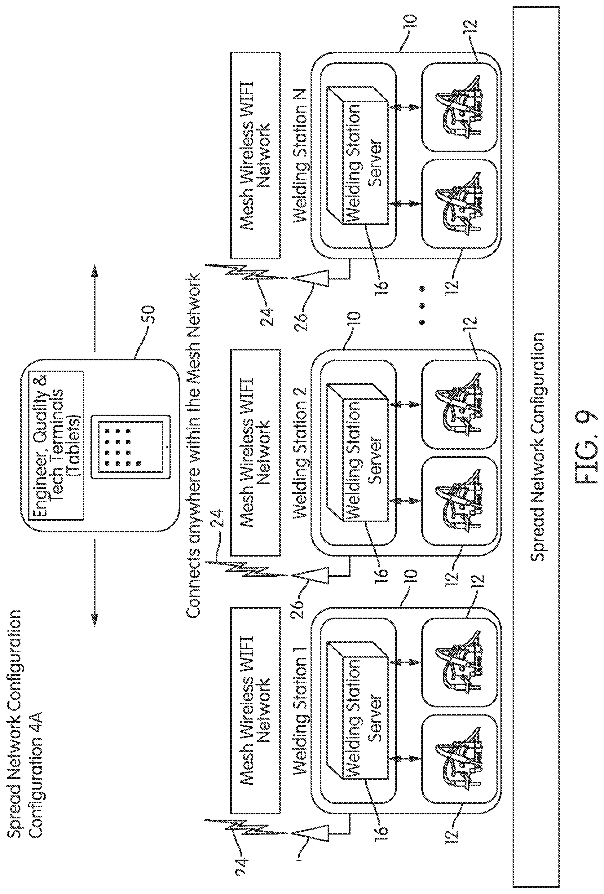
FIG. 9 is a schematic diagram of a plurality of welding stations in communication with an intermediate computer system (Engineer, quality and Tech terminals) through a wireless (e.g., WiFi) communication channel, according to an embodiment of the present disclosure;
FIG. 10 is a schematic diagram of a plurality of welding stations in communication with a computer system through a wireless (e.g., WiFi) communication channel, according to an embodiment of the present disclosure;
FIG. 11 is a schematic diagram of a plurality of welding stations in communication with a plurality of intermediate computer systems (Engineer, quality and Tech terminals) which in turn are in communication with a cloud server, according to an embodiment of the present disclosure;
FIG. 12 shows an example graphical user interface ("GUI") for a "Main Screen" of an application for cloud based universal data logging (uLog) implemented by a computer system at the welding station, at the intermediate computer system or at the cloud server, according to an embodiment of the present disclosure;
FIG. 13 shows an example GUI for a "Live Log" screen of the application for cloud based universal data logging (uLog) showing voltages versus time at one welding station, according to an embodiment of the present disclosure;
FIG. 14 shows an example GUI for a "Get Log" screen of the application for cloud based universal data logging (uLog) showing weld data parameters including type of weld event, time, zone, weld travel speed, lead wire travel speed, according to an embodiment of the present disclosure;
FIG. 15 shows an example GUI for a summary report screen of the application for cloud based universal data logging (uLog) displaying various welding parameters including weld time, weld station identification number, weld arc voltage, etc., according to an embodiment of the present disclosure;
FIG. 16 shows an example GUI for a "Save Data on Log" screen of the application for cloud based universal data logging (uLog) displaying various, according to an embodiment of the present disclosure;
FIG. 17 shows an example GUI for an "Analytics" screen of the application for cloud based universal data logging (uLog) showing two icons for selecting a type of analysis performed (e.g., trends, moving average), according to an embodiment of the present disclosure;
FIG. 18 shows an example GUI for a "Welding Parameter" screen of the application for cloud based universal data logging (uLog) showing two various for selecting a type of function to be performed (e.g., get welding parameters (WP), set welding parameters (WP), view welding parameters WP . . . ), according to an embodiment of the present disclosure;
FIG. 19A depicts schematically an example of a spool that is configured to carry a weld wire, according to an embodiment of the present disclosure;
FIG. 19B depicts schematically a lateral view of a hub-transducer that is configured to measure a weight of the spool, according to an embodiment of the present disclosure;
FIG. 19C depicts another lateral view of the hub-transducer showing the positioning of transducer elements or strain sensors/gauges for measuring weight strain when the spool is mounted on the hub, according to an embodiment of the present disclosure;
FIG. 20 depicts schematically an arrangement where a weld wire in spool mounted to hub is pulled by a motor assembly for feeding the wire 82 to the weld device (not shown), according to an embodiment of the present disclosure;
FIG. 21 is a flow chart depicting a process of comparing the measured weight and the theoretical weight determined based on the wire feed speed, according to an embodiment of the present disclosure;
FIGS. 22A and 22B depict enlarged lateral cross-sections of the motor assembly, according to an embodiment of the present disclosure; and
FIG. 23 is a diagram of a configuration of the welding system depicting the interconnections of various components of the system, according to an embodiment of the present disclosure.
DETAILED DESCRIPTION OF THE INVENTION
The universal cloud logging system (herein also as "uLog", or "uLog system", or "uCloud") is a system of software, hardware, equipment and telecommunications networks which seamlessly gather welding data to provide for quality control and management, weld data logging, task and project management, safety and inspection control and management, real time weld activity monitoring and data reporting and visualization. The uLog system can use wired systems and devices and/or wireless systems and devices and/or Bluetooth systems and devices and/or cloud-based systems and devices. The uLog system can use software technology, App technology, mobile device and desktop technology, telecommunications technology and other technologies in products, apparatus, systems, processes and methods achieving high quality welding, inspection, control, management and safety results. The uLog system can be used in onshore, offshore, ship-based, platform-based, structure-based, or other construction conditions. In an embodiment, the uLog can process Bluetooth communications and data can be transmitted to the uLog for processing by Bluetooth or any other wireless means.
In an embodiment uLog has tools which seamlessly gather welding data and/or welding data logs. The uLog system can in its many and varied embodiments use welding data and other pipeline construction and related data to produce one or more of the following: analytic results, field reports, control data, quality control data, automatically generated administrative reports, daily summaries, data archives, welding records, materials use data, quality control records and project management records.
In an embodiment, the uLog can be used to maintain and/or generate procedure qualification records ("PQR") and data relating thereto. The uLog functionality can also be used to record, develop, maintain and manage welding procedure specifications ("WPS").
The uLog can provide for a user to see, record, track, measure, and analyze log data regarding one or more welds and/or welding activities and/or pipeline construction and/or coating activities and/or inspection activities and/or management activities. By use of the uLog and its analytical functionalities a user can achieve improved weld quality and quantify welding process results. In its many and varied embodiments, the uLog can have functionalities to process data in real-time or based upon historical data. This allows a user to make decisions in real time and/or based upon historical data. In an embodiment, the uLog can provide a user real time data regarding any aspect of ongoing welding, coating, inspection, pipe handling, project management, pipeline construction and/or construction activities and achieves real-time quality control of welding and/or welding activities and/or other activities regarding pipeline construction. In another embodiment, the uLog can also provide functionalities regarding construction management, project management, accounting, inventory and materials management, as well as financial controls and auditing of both financials and materials. The uLog can also provide functionalities regarding human resources management and timekeeping, as well as payroll accounting and support.
Without limitation, various embodiments of the present disclosure can be, for example, embodied as a computer system, a method, an App, a cloud-based service, or a computer program product. Accordingly, various embodiments can take the form of an entirely hardware embodiment, an entirely software embodiment (e.g., one or more computer application, such as an "App" (or "App") to be implemented on a mobile device and/or an application to be implanted on a desktop computer), or an embodiment combining software and hardware aspects. Furthermore, embodiments can take the form of a computer program product stored on a computer-readable storage medium having computer-readable instructions (e.g., software) embodied in the storage medium. Various embodiments can take the form of web-implemented computer software. Any suitable computer-readable storage medium can be utilized including, for example, hard disks, compact disks, DVDs, optical storage devices, solid state storage devices, and/or magnetic storage devices.
Various embodiments are described below with reference to schematics, block diagrams, images and flowchart illustrations of methods, apparatuses (e.g., systems) and computer program products. It should be understood that each block of the block diagrams and flowchart illustrations, and combinations of blocks in the block diagrams and flowchart illustrations, respectively, can be implemented by a computer executing computer program instructions. These computer program instructions can be loaded onto a general purpose computer, special purpose computer, or other programmable data processing apparatus to produce a machine, such that the instructions which execute on the computer or other programmable data processing apparatus create means for implementing the functions specified in the flowchart block or blocks.
These computer program instructions can also be stored in a computer-readable memory that can direct a computer or other programmable data processing apparatus to function in a manner such that the instructions stored in the computer-readable memory produce an article of manufacture that can be configured for implementing the function specified in the flowchart block or blocks. The computer program instructions can also be loaded onto a computer or other programmable data processing apparatus to cause a series of operational steps to be performed on the computer or other programmable apparatus to produce a computer implemented process such that the instructions that execute on the computer or other programmable apparatus provide steps for implementing the functions specified in the flowchart block or blocks.
Accordingly, blocks of the block diagrams and flowchart illustrations support combinations of mechanisms for performing the specified functions, combinations of steps for performing the specified functions, and program instructions for performing the specified functions. It should also be understood that each block of the block diagrams and flowchart illustrations, and combinations of blocks in the block diagrams and flowchart illustrations, can be implemented by special purpose hardware-based computer systems that perform the specified functions or steps, or combinations of special purpose hardware and other hardware executing appropriate computer instructions. Implementation can also be by special purpose software and equipment running special purpose software and/or applications. The entire system can be accessible from various computer platforms, including mobile devices.
Numeric values and ranges herein, unless otherwise stated, also are intended to have associated with them a tolerance and to account for variances of design and manufacturing. Thus, a number is intended to include values "about" that number. For example, a value X is also intended to be understood as "about X". Likewise, a range of Y-Z, is also intended to be understood as within a range of from "about Y-about Z". Unless otherwise stated, significant digits disclosed for a number are not intended to make the number an exact limiting value. Variance and tolerance is inherent in mechanical design and the numbers disclosed herein are intended to be construed to allow for such factors (in non-limiting e.g., .+-.10 percent of a given value). Likewise, the claims are to be broadly construed in their recitations of numbers and ranges.
FIG. 1 contains images of land based pipelines. The uLog can be used in the manufacturing of any pipeline in any construction environment. Construction environments can be on land, off shore, both on land and off shore, under water, sub-sea, on a facility, on a ship, on a barge, on a platform, on a structure, in space, or in any other construction environment. For example, the uLog can be used in the control of welding of pipelines.
FIG. 2 shows a welding station 10, according to an embodiment of the present disclosure. The uLog can be used in conjunction with the weld station 10. The uLog can process data from the weld station 10. The weld station may include a welding machine or welding system 12, a welder 14 or an automated or robot welding system. In an embodiment, the welding machine or welding system 12 is an orbital welding machine. An example of a welding machine or welding system 12 is described in U.S. Pat. No. 3,974,356 to Nelson et al., issued on Aug. 10, 1976, the entire content of which is incorporated herein by reference. The welding station 10 may be controlled by a computer system 16 to control the welding process and also acquire data about the welding process. The uLog implemented on the computer system 16 can control the welding station 10 including the welding machine 12 and can also process data from a workpiece 18 such as a pipe and/or regarding work or welding applied upon the workpiece (e.g., the pipe) 18.
FIG. 3 shows a plurality of pipeline welding stations 10 (a pipeline welding spread 20), according to an embodiment of the present disclosure. The uLog can be used on the pipeline welding spread 20. The uLog can process data from one or more welding stations 10 in the pipeline welding spread 20. In an embodiment, the uLog can process data from a number or many welding stations 10. There is no limitation to the locations of the weld stations 10. Pipelines 18 can be very long and the one or more stations can be at any location without limitation. Further, the uLog supports processing data from multiple projects and/or activities and/or tasks and/or people at the same time. The uLog user expertise can be used across projects and well as within projects. The uLog allows a user to work with data from one or a number of projects simultaneously or in series, in real-time or on an historical basis.
FIG. 4 is a schematic diagram of a system with a plurality of welding stations 10 in communication with a plurality of control and log collection stations (computer systems) 16, according to an embodiment of the present disclosure. In an embodiment, welding data can be collected at a log collection station 16 associated with a welding station 10. The control and log collection stations 16 can process data for one or more welds and/or weld stations 10. The data collection and/or processing can originate from pipeline construction, the weld station equipment, operator, welder or other data entry means. In non-limiting example, equipment processors, embedded processors, computers, sensors, process control devices, wired or wireless analog and digital devices and hand-held data processors can be used to gather, communicate and/or process weld station and/or weld system data. In an embodiment, one or more technicians can control the weld station(s) 10 and control and log collection station(s) 16. There is no limit to the number of log collections stations 16 which can be used with uLog. The log collection station 16 together with the weld station 10 for a welding system 22.
FIG. 5 is a schematic diagram of a system with a plurality of welding stations 10 in communication with a plurality of control and log collection stations 16, according to another embodiment of the present disclosure. In an embodiment, welding data can be collected from each welding station 10 or welding system 22. In another embodiment, welding data can be collected from a number of stations or welding systems 10. There is no limit to the number of welding stations 10 and/or welding systems 22.
FIG. 6 is a schematic diagram of welding station 10 in communication with a wireless network 24 via a wireless connection (e.g., WiFi connection) 26, according to an embodiment of the present disclosure. For example, the welding station 10 can be provided with a wireless communications capability, such as Bluetooth, WiFi, cellular communication, satellite phone, or other wireless means. For non-limiting example, a welding station 10 can have one or more of a welding process computer, server or processing unit 16 which can gather and process welding system data. As shown in FIG. 6, the welding station 10 includes two welding machines or welding systems 12. In an embodiment, the weld systems 12 include an orbital weld system. One of the welding machines 12 is a clockwise (CW) welding machine or system and the other welding machine 12 is a counterclockwise (CCW) welding machine or system.
FIG. 7 is a schematic diagram of a plurality of job sites 30 in communication with a cloud server 32 via a worldwide network (internet), according to an embodiment of the present disclosure. The uLog can be configured on a local, regional, project or worldwide basis. The implementation of the uLog is without geographic limitation. One or many jobsites 30 can be networked with the uLog. In an embodiment, users, personnel, managers, engineers, departments, companies, specialists, workers, customers and a multitude of other parties can be networked to uLog. Each job site 30 includes a welding station 10 operated by welder 14 (as shown in FIG. 2), a lead technician 34, and a welding engineer 36, etc. Each job site 30 is configured to communicate with the cloud server 32 via a dedicated communication line or communication channel 40 or via the internet 42. The cloud server 32 can be accessed by a system manager 38 and Engineering 39. A storage device 33 in communication with the cloud server can be provided for storing welding data.
FIG. 8 is a schematic diagram of a plurality of welding stations 10 in communication with intermediate computing devices 50 operated by technical managers (lead technicians 52, inspectors 54, engineers 56, etc.) through communication channels or lines 58, according to an embodiment of the present disclosure. For example, each welding station 10 can communicate with one or more of the intermediate computing devices 50. Similarly, each intermediate computing device 50 is configured to communicate with one or more of the welding stations 10. The intermediate computing devices 50 are in turn configured to communicate with cloud server 32 through the internet 42. Portions of the uLog program are configured to run on the cloud server 32, other portions of the uLog are configured to run on the intermediate computing devices 50 and yet other portions are configured to be implemented on the welding station computer/server 16. Each portion or component of the uLog operates in synergy with other portions or components to provide a seamless management of the overall system. In an embodiment the uLog can optionally have differentiated worldwide network capabilities and spread network capabilities. In another embodiment, all capabilities are fully integrated; and in yet another embodiment can be without differentiation.
FIG. 9 is a schematic diagram of a plurality of welding stations 12 in communication with an intermediate computer system 50 (operated by Engineer, Quality and Tech terminals) through a wireless (e.g., WiFi) communication channel 26 to wireless communication network 24, according to an embodiment of the present disclosure. The intermediate computer system can be any type of a computing device including a tablet, a phone, smartphone, PDA and/or other wireless device(s) for data entry, processing, communications, input, output and other functions. The intermediate computer runs the uLog program and can be operated by engineering, quality control, users, supervising technicians and others. In an embodiment, the uLog running at the intermediate computer 50 provides data, processes data and communicates data or information with the welding station computer 16 located at each of the welding stations 10.
FIG. 10 is a schematic diagram of a plurality of welding stations 10 in communication with intermediate computer system 50 through a wireless (e.g., WiFi) communication channel 26 into wireless communication network 24, according to an embodiment of the present disclosure. FIG. 10 shows a spread network configuration. Intermediate computer system 50 has wireless capability such as WiFi or Cellular (3G, 4G, etc.) allowing it to communicate wirelessly with any of the welding stations 10. The intermediate computer 50 can be any type of mobile wireless device, such as a smartphone, table or PDA that can connect anywhere in the wireless network 24. In an embodiment, the uLog program or system can use a mesh network processing data through a mesh wireless (e.g., WiFi) network 24. For example, a welding station server 16 of a welding station 10 can communicate with a uLog device 50 via a mesh wireless network 24 and can connect anywhere within the mesh network 24. In an embodiment, mesh networking can be used in a spread network configuration.
FIG. 11 is a schematic diagram of a plurality of welding stations 10 in communication with a plurality of intermediate computer systems 50 (operated by Engineer 56, inspectors 54, lead technician 52, etc.) which in turn are in communication with cloud server 32, according to an embodiment of the present disclosure. FIG. 11 shows a data flow diagram for an overall network configuration. In an embodiment, the overall network configuration can be a worldwide network configuration. The overall network configuration can be used by managers, engineers, inspectors, technicians, lead technicians, welding engineers, welders and weld stations, as well as others. In an embodiment, the uLog overall network configuration can optionally have data flow differentiated by worldwide network capabilities and spread network capabilities. In another embodiment, all capabilities are fully integrated without differentiation. Similar to the configuration shown in FIG. 8, for example, each welding station 10 can communicate with one or more of the intermediate computing devices 50. Each intermediate computing device 50 is configured to communicate with one or more of the welding stations 10. The intermediate computing devices 50 are in turn configured to communicate with cloud server 32 through the internet 42. Portions of the uLog program are configured to run on the cloud server 32, other portions of the uLog are configured to run on the intermediate computing devices 50 and yet other portions are configured to be implemented on the welding station computer/server 16. Each portion or component of the uLog program or system operates in synergy with other portions or components to provide a seamless management of the overall system. In an embodiment the uLog can optionally have differentiated worldwide network capabilities and spread network capabilities. In another embodiment, all capabilities are fully integrated; and in yet another embodiment can be without differentiation.
FIG. 12 shows an example graphical user interface ("GUI") for a "Main Screen" 60 of an application for cloud based universal data logging (uLog) implemented by a computer system at the welding station 10, at the intermediate computer system 50 or at the cloud server 32, according to an embodiment of the present disclosure. In an embodiment, the uLog provides numerous features for data retrieval, data analysis, data analytics, data mining, data logging and reporting. The GUI 60 includes a plurality of icons 61 through 68. Each icon when activated (for example by a mouse click or by finger touch) opens an application. For example, icon 61 is associated with application Admin configured to be operated by the administrator for setting up administrative features of the uLog. The icon 62 is associated with Weld parameters configured for inputting weld parameters. The icon 63 is associated with the function "Log." The icon 64 is associated with "Report". The icon 65 is associated with "Job Set up." The icon 66 is associated with "Analytics." The icon 68 is associated with uploading and saving data on the Cloud (i.e., saving data on the cloud server 32 or storage device 33. Therefore, as it can be appreciated, the uLog universal logging functionalities can include, but are not limited to processing data and information regarding: administration, weld parameters, logs, records, reports, job setup, inspection, quality control, coating, pipe handling, user and/or administrative diagnostics, analytics and data for processing locally and/or by cloud-based means.
The scope of this disclosure encompasses the methods and means to achieve the disclosed pipeline welding and construction support, as well as encompassing any article, product, means, and methods for producing and using any software, application, computer executable code, programming, logical sequences, or other form of electronic or automated means to achieve and/or use the methods herein. Such products, articles and means include for example, but are not limited to, a software application product provided on a fixed media, such as a disk, or in a physical memory, or in a memory stick, or as a software application product, or as an application provided by digital download, or provided by other means. This application expressly encompasses installed, uninstalled, compiled and not compiled versions of any software product or equivalent product capable of being used, implemented, installed or otherwise made active to use, achieve and/or practice the methods disclosed herein. In addition to its normal and customary meanings, the recitation "computer readable program code means" is intended to be broadly construed to encompass any kind and type of computer readable program code, executable code, software as a service, web service, cloud service, or cloud-based process, embedded application, software application product provided on a fixed media, such as a disk, or in a physical memory, or in flash memory, or in a memory stick, or as a software application product, or as an application provided by digital download, or encoded on programmable hardware, or provided by other means which can be employed to make, use, sell, practice, achieve, engage in, produce, function or operate the methods disclosed herein. The application is to be broadly construed in this regard and not limited to any means of delivery or to any product form for providing or using, achieving and/or practicing the computer readable program code products, means and/or methods disclosed herein. In embodiments, all of the methods herein can be produced and provided to a user as a software product(s), software application(s), computer readable program code means(s) or any other article(s) or device(s) which can be used to achieve any, some or all of the results, calculations and/or numerical methods disclosed herein.
In an embodiment, a user can setup a job locally or in the cloud. In a cloud-based example, a user can use and/or inherit job related information from the cloud to be retrieved by or pushed to the user's device and or machine (e.g., computer 16 associated with welding machine 12). Setup of a job on or by means of the Cloud, can activate device 16 to inherit the job related information from the cloud to be pushed to the device and/or machine 16. In another embodiment, uLog provides single point data integrity maintenance. Machine to cloud (M2C) and cloud to machine (C2M) data storage and retrieval are also functions provided by uCloud.
In an embodiment, a centralized location can be used where the details of the job client can be entered, processed and maintained, or retrieved automatically by uLog. The uLog can also use a distributed approach to data management and processing. The uLog can create and attach job specific parameter files to be deployed on a job managed by the right authorities with assigned user privilege levels. This job related information can be inherited by the assigned user and pushed to computers 16 associated with welding machines 12 (cloud to machine; "C2M"). Changes made to the job related information are collected from computers 16 associated with welding machines 12 and synced (synchronized) back to the (machine to cloud; "M2C") cloud (i.e., cloud server 32). The cloud server 32 provides a single point where some or all data are processed by uLog.
The uLog can process, record analyze and use data from one, more or all of the following types of equipment: welding machines, pipe bending equipment, pipe handling equipment, end prep equipment, clamps, padding and/or crushing equipment, double jointing equipment and/or systems, weighting equipment and/or systems, conveying equipment and/or systems, laybarge equipment and construction/management systems. The uLog can also be an enterprise resource planning (ERP) system or work with an ERP system.
The uLog can use and/or process data from any one or more of the following types of welding equipment. Such welding equipment can be for example, but is not limited to: manual welding equipment, automatic welding equipment, external welding machine, internal welding machine, a single torch welder, a dual torch welder, a multitorch welder, high productivity welding systems, an inspection system, an internal inspection system, an external inspection system.
The uLog can use and/or process data from any one or more of the following types of pipe bending equipment: bending machines, wedge mandrels, hydraulic wedge mandrels, plug mandrels, hydraulic plug mandrels, pneumatic mandrels, pneumatic wedge mandrels. The uLog can use and/or process data from any one or more of the following types of pipe handing equipment: DECKHAND.RTM. equipment (CRC-Evans, Houston, Tex.), vehicles, construction vehicles and equipment adapted to produce a data for use or processing. The uLog can use and/or process data from any one or more of the following types of equipment: bending sets and dies, angle measurement equipment and devices, compressors, cradles, booms and/or supports, demagnetizing equipment, tires, wheels, and track wheels.
The uLog can use and/or process data from any one or more of the following types of equipment: an end prep station for increasing land on pipe bevel, line-up station for pipe alignment and an external weld, capping fill station for applying external weld cap, internal weld station for applying internal weld, power trailer or containers with diesel generator and welding rectifiers, pipe skids and supports for transferring the pipe from station to station, internal pneumatic line-up clamps and pipe facing machines, sub-arc welding machines and processing equipment.
The uLog can also use and/or process data from any one or more of the following types of equipment: Laybarge Equipment, pipe handling, double jointing, joint coating equipment, coating equipment, onshore equipment, offshore equipment, deepwater equipment, shallow-water equipment, roller units, conveyers, pipe transfer equipment, support frames, support units, roller modules, longitudinal conveyer roller modules, pipe elevators, pipe supports, roller type pipe supports (PSA and PSF), pipe transfer carriages, PTC-V pipe transfer carriages, stern pipe supports, adjustable height pipe supports, SPSA roller-type stern pipe support, TPSA track-type pipe support, transverse conveyers, walking beam type conveyers and TV-C-W transverse conveyers.
The uLog can use and/or process data from any one or more of the following types of processes and methods: welding, pipe welding, pipeline welding, coating, joint coating, field joint coating, inspection, quality assurance, nondestructive testing, heat treatment, management, offshore management, onshore management, managed services, welding support, spoolbase management and micro-alloying.
In an embodiment, uLog can be used for deployment of daily job statistics from cloud and from mobile device. Creation of PQR and/or WPS and/or daily reports can be produced from a mobile platform and/or on cloud, or by other means. Analytics of collected data on cloud and mobile device provide feedback to the control system to improve quality and defect prediction. In an embodiment uLog provides integrated pipe joint tagging, synced with data logs. The uLog can also use single point Capture of data logs, provide machine setup information and process software revisions.
The uLog can also execute automatic error reporting of machine status, automatically stamp a job location on job records, as well as perform synchronized capture of job related parameter change notes from all users for a given project. Additionally, Consolidated Project related report to customers from single point can also be generated by uLog.
FIG. 13 shows an example GUI for a "Live Log" screen of the application for cloud based universal data logging (uLog) showing voltages versus time at one welding station, according to an embodiment of the present disclosure. In an embodiment, the uLog executes a centralized data capture of data from all pipe welding handling, coating related machines, as well as each of the types of data relevant to such machine and activities. Current live activity summary for weld, coating and inspection can be generated. Various parameters are reported on a table including: an event number, a time stamp, a zone identification, a tilt in degrees of the welding device or weld system, a travel speed of the welding device, a lead volts or voltage applied to the weld wire, a lead amps (A) or current applied to the weld wire, a lead wire speed or the speed of the weld wire, etc. For example, various parameters including lead weld wire speed (i.e., speed of the weld wire) and the speed of the welding device (travel speed), as well as other parameters can be reported in a form of table and/or graphs. In addition, a voltage applied to the weld wire can also be displayed in a table and/or as a graph versus time.
Optionally, electronic signatures to PQR/WPS documents can be supported by uLog. Optionally, the uLog can process system parameter version control and rollback. In an embodiment, the uLog also has functionalities for deployment of daily job statistics from cloud and/or mobile devices. For non-limiting example, the uLog can execute data management and can provide the user reports regarding the number of welds done for a given time period (e.g., per hour, in one day, in one week, etc.) and can report the amount of a consumable (e.g., welding material) used for a given period (e.g., per hour, in one day . . . ) or other measure. Job and error reports can also be produced by uLog.
In an embodiment, uLog can send an email and/or SMS (text message) or other notification to appropriate authorities. The uLog can also be used to for financial functions, accounting auditing, time keeping and other management tasks. For example, the uLog can invoice a customer in a timely manner. In an embodiment, the invoice can be generated based on the number of welds, or based on the use and/or waste of consumable. The uLog provides a quantification system and supports the efficient invoicing and accounting of pipeline welding projects.
The uLog can also be used for automatic resupply of materials and/or equipment and/or other resources or inventory on a project. The many and varied functions of the uLog disclosed herein can reduce disruption on the job, downtime, wastage and other negative occurrences during construction.
FIG. 14 shows an example GUI for a "Get Log" screen of the application for cloud based universal data logging (uLog) showing weld data parameters including type of weld event, time, zone, weld travel speed (travel speed of the welding system), lead wire travel speed (weld wire speed), according to an embodiment of the present disclosure. FIG. 14 shows various parameters that are reported on a table including: a weld identification or type number, an event number, a time stamp, a zone identification, a tilt in degrees of the welding device or weld system, a travel speed of the welding device, a lead volts or voltage applied to the weld wire, a lead amps (A) or current applied to the weld wire, and a lead wire speed (the speed of the weld wire). In an embodiment, uLog can automatically stamp job location on job records. In other examples, the data logs can be time stamped and can reflect the time zones, as shown in the table depicted in FIG. 14. Time stamps can be synchronized from the GPS and/or based upon data present and/or pushed to the uLog such that the logs reflect the time zone they were captured in.
FIG. 15 shows an example GUI for a summary report screen of the application for cloud based universal data logging (uLog) displaying various welding parameters including weld time, weld station identification number, weld arc voltage, etc., according to an embodiment of the present disclosure. In an embodiment, uLog can create and/or generate PQR and/or WPS and/or summary reports and/or daily reports all done from mobile platform and on cloud. PQR, WPS, summary and daily reports can be manually produced or automatically generated. The uLog can generate one, more or all of these types of reports on a schedule, ad hoc or simultaneously. The uLog provides the benefit of processing common and consistent data. The same collected data can be used to generate reports at the same or different locations and/or output devices.
Rules of reporting can be established on uLog and can be configurable. In an embodiment, critical data for a given project can be synchronized on cloud. The uLog provides for the creation of a project qualification binder that is to be sent to user and/or client of a user and/or other recipient at the end of a qualification process with electronic signatures for approval. The uLog reduces time and expense in creation of these reports and approved documents.
FIG. 16 shows an example GUI for a "Save Data on Log" screen of the application for cloud based universal data logging (uLog) displaying various, according to an embodiment of the present disclosure. The uLog provides data storage services of an unlimited nature. The pipeline construction industry is worldwide and its projects can be geographically dispersed. Additionally, pipeline construction can occur under harsh environments and climates. The uLog allows data to be stored and protected from anywhere a user and/or equipment can be present. The data can also be synchronized or otherwise processed. For example data can be saved to the cloud from a job, log, welding station, weld parameter, reports and job locations. In an embodiment location data can be saved in addition to technical and/or management data.
FIG. 17 shows an example GUI for an "Analytics" screen of the application for cloud based universal data logging (uLog) showing two icons for selecting a type of analysis performed (e.g., trends, moving average), according to an embodiment of the present disclosure. In an embodiment, uLog analytics can process and provide data trends, moving averages and/or any type of data processing which a user requires. In an embodiment, uLog can have pipeline data cloud logging, reporting and analytics systems. For example, analytics can be conducted on collected data to provide feedback to the control system to improve quality and defect prediction of welds and/or construction equipment, activities and operations. In an embodiment, data can be collected by means of the cloud and/or one or more mobile devices. In an embodiment, the uLog supports a synchronized capture of job related parameter change notes from all users for a given project. In another embodiment, uLog can monitor, analyze and report current live activity and provide live summary data and summary report(s) for welding, coating and inspection activities. The uLog system can execute system parameter version control and rollback. The uLog system also achieves single point capture of data logs, machine setup information and software revisions. In yet another embodiment, integrated pipe joint tagging can be achieved and synced with data logs.
FIG. 18 shows an example GUI for a "Welding Parameter" screen of the application for cloud based universal data logging (uLog) showing two various mechanisms for selecting a type of function to be performed (e.g., get welding parameters (WP), set welding parameters (WP), view welding parameters WP . . . ), according to an embodiment of the present disclosure. In an embodiment, uLog cloud based logging can execute any of the following activities and/or processes: get weld parameters, set weld parameters, view and process weld parameter notes, view and process weld parameter passes, as well as rolling back weld parameters. In an embodiment the uLog can contain any, more or all of the following: Pipeline Miles reward(s) functionalities, Pipe Miles functionalities, uLog functionalities, M2C functionalities and C2M functionalities.
A welder or weld technician may waste weld wire if the welder replaces the spool too soon before most of the wire is consumed. In addition, the welding process can be interrupted if the spool runs out of wire during the weld process causing downtime and defect repair. One method to address these problems in the present embodiment is to rely on wire feed motor speed to determine lead wire speed and thus determine the length of weld wire that is consumed during a certain period of time. However, this method may carry errors due to slippage of the wire on the wire feed motor wheel or incorrect starting weight. As a result, a determination of the length of wire based on the speed of the motor may not be accurate. In addition, an incorrect starting weight may lead the user to believe that enough wire is available in the spool to perform a weld (if the initial or start weight is over estimated for example) whereas in reality the amount of wire remaining in the spool is not sufficient to complete a weld. In order to cure this deficiency, a device is used to measure the weight of the spool of wire in real time while the motor pulls the wire weld. By measuring the weight of the spool, the user or welder can determine if enough wire is remaining in the spool to complete a weld before the weld is started. As a result, the weight of the wire can be determined at all times which substantially eliminate the uncertainty due to slippage or unknown starting weight of the spool. Furthermore, the weight can be compared to the lead wire feed speed to determine whether the wire is feeding at the intended speed.
FIG. 19A depicts schematically an example of a spool 80 that is configured to carry a weld wire, according to an embodiment of the present disclosure. FIG. 19B depicts schematically a lateral view of hub-transducer 82 that is configured to measure a weight of the spool 80, according to an embodiment of the present disclosure. FIG. 19C depicts another lateral view of the hub-transducer showing the positioning of transducer elements or strain sensors/gauges 84 for measuring weight strain when the spool 80 is mounted on the hub 82, according to an embodiment of the present disclosure. As shown in FIG. 19B, when the spool is mounted on the hub 82, the weight of the spool will exert a force on the axle 82A of the hub 82 which will in turn exert a strain on the lateral hub 82B. Strain sensors 84 are provided on the lateral hub 82B to sense the strain applied by the weight of the spool. Examples of strain sensors that can be used to measure strain are piezo-electric elements. The strain sensors 84 convert a strain force into a measured voltage. Hence, by measuring the voltage, one can determine the weight of the spool 82. In an embodiment, a temperature sensor (not shown) can be provided in the hub and positioned to capture the temperature of the hub in order to apply corrections to the strain sensor measurement for a wide range of temperatures.
FIG. 20 depicts schematically an arrangement where a weld wire 86 in spool 80 mounted to hub 82 is pulled by a motor assembly 90 for feeding the wire 82 to the weld device (not shown), according to an embodiment of the present disclosure. The weld wire 86 is pulled by the motor assembly 90. In an embodiment, the rotation speed of the motor assembly (used to determine lead wire speed) can be measured by sensor 92. In an embodiment, the motor assembly uses a motor with an adequate rotational speed (rotation per minute or RPM measured by sensor 92) to achieve a desired feed speed of the wire to the weld device. In another embodiment, the rotation of the motor assembly can be changed according to a desired wire feed (lead wire speed) speed measured by sensor 92. The motor assembly 90 is configured to supply or feed weld wire 86 to the welding device 100 to weld a workpiece 101 (e.g., a pipe, etc.). A speed of the welding device 100 is measured by speed sensor 102. The speed sensor 102 is also configured to measure various parameters of the weld or weld data.
FIGS. 22A and 22B depict enlarged lateral cross-sections of the motor assembly 90, according to an embodiment of the present disclosure. As shown, the motor assembly includes a motor 91 and feed wheel 93. The motor 91 engages the feed wheel 93 to rotate the feed wheel 93. The motor assembly 90 further includes a pinch roller 95 that comes in contact with feed wheel 93. A tension spring 97 is provided to bias the pinch roller 95 towards the feed wheel 93. The weld wire 86 is inserted between the feed wheel 93 and the pinch roller 95. Hence, the pinch roller 95 pushes on wire 86 to bring the wire 86 in contact with the feed wheel 93. As a result a rotation of the feed wheel 93 and the pinch roller 95 as illustrated by the arrows in FIG. 22B would be translated, in theory, into a linear movement of the wire 86, as shown by the arrow. In an embodiment, teeth are provided on the feed wheel 93 so as to grasp the wire 86 through friction and force the wire 86 to move. However, situations may occur where the wire 86 is not fully gripped by the feed wheel 93. In this case, the wire 86 may slip because although the feed wheel 93 rotates, this rotation of feed wheel 93 does not translate into precise linear movement of the wire 86. For example, this may occur when, the teeth on the feed wheel 93 are worn (thus not providing sufficient friction to grasp the wire 86), or when the pinch roller 95 is worn (thus not exerting enough pressure or force on the wire 86 to the push the wire 86 against the feed wheel 93), or when the tension spring 97 loses its preload (thus leading to the pinch roller 95 not exerting enough pressure or force on the wire 86), or when the nut 99 holding the feed wheel 93 becomes loose (thus leading to feed wheel not grasping the wire 86), or any combination thereof. As shown in FIG. 22A, the motor assembly 90 includes rotation speed sensor 92 that is configured and arranged to measure the rotation speed of the motor 91. An output 98 is provided for inputting and outputting data into and from the motor assembly 90, the data including the speed of the motor 91. The data from output 98 is sent to computer 16 associated with welding station 10.
FIG. 23 is a diagram of a configuration of the welding system depicting the interconnections of various components of the system, according to an embodiment of the present disclosure. As shown in FIG. 23, a rotation speed of the motor assembly 90 is measured by rotation speed sensor (RPM sensor) 92. In addition, the weight of the weld wire spool 80 is measured by the weight sensor(s) 84 in the hub-transducer 82. The speed of the welding device 100 is measured by the speed sensor 102. All parameters or data measured by the rotation speed sensor 92, the weight sensor 83 and the speed sensor 102 are input into computer 16 at wed station 10. In an embodiment, the computer 16 can be managed by intermediated computer 50. Intermediate computer 50 can be a wireless device such as a tablet, a mobile device, a smart phone, a laptop, etc. Therefore, the intermediate computer 50 can have access to the data at the computer 16 including the data from RPM sensor 92, weight sensor 84 and speed sensor 102. The intermediate computer 50 is further in communication (e.g., wirelessly) with the cloud server 32 where the data from the computer 16 can be stored and/or further processed. In an embodiment of the present disclosure, the intermediate computer is not used. In which case the computer 16 is connected directly (e.g., wirelessly) to the cloud server 32.
As stated in the above paragraphs, due to potential slippage, the measurement of the speed of the motor assembly (e.g., speed of the feed wheel 93) alone, in some embodiments, may not be sufficient to provide an accurate amount of weld wire that is used or consumed by the weld machine or system. Indeed, even if a rotation of the feed wheel 93 is measured accurately, the rotation of the wheel would be translated in theory into a movement and therefore into a certain length. However, due to slippage, the wire does not move and hence the length determined based on the rotation of or rotation speed of the wheel does not correspond to a real wire length. As a result, a weight of the spool of weld wire may also be measured. In an embodiment, the weight of a new and unused wire spool is about 15 kgs (15000 grams). In an embodiment, the weight of the wire spool is measured with a precision of about 100 grams over 15000 grams, that is with a precision of approximately 0.7%. Therefore, the weight provides a relatively good measurement method to determine the amount of weld wire remaining in the spool. In an embodiment, the weight of the spool is captured or measured periodically and is logged with a time stamp and communicated to the uLog every time the spool rotation stops. An indicator such as a buzzer or light flashing or the like can indicate to the welder that it is time to reload another spool. In addition, the weld machine may not commence a weld operation in this situation, in one embodiment. The indicator can indicate a weight threshold at which a complete weld cannot be completed.
In an embodiment, RF modules are further provided to read a spool serial number, manufactured weight of the spool, spool type, project name, and any detail that is fed on the RF tag mounted on the spool. This data can be transferred on the cloud via the uLog with any additional detail needed. If an old spool is reused, the system will compare the serial number against a database of already used spools and extract the last available weight from the cloud, compare the same against the new weight reading, prior to the start of work. A buzzer or indicator light is available on the system to indicate to the operator, that the details on the RF Tag have been read and communicated via CAN. The use of RF system will eliminate any manual book keeping work needed to keep track of the number of spools used, their serial numbers and further identify the work stations they are used at. In case weld wires with wrong compositions/diameters are shipped out, the system can identify this from the RF tag properties, alarming the operator of this deviation. This can go fairly unnoticed if the system was entirely manual.
In an embodiment, a difference DW between a weight W1 measured at time T1 and a weight W2 measured at a later time T2 can be calculated. The difference in weight DW (where DW=W1-W2) corresponds to the weight of wire that is consumed during a welding process. This weight difference DW can be compared to a theoretical weight TW. The theoretical weight TW can be obtained using the rotation speed R of the motor or a linear speed of the wire S (the linear speed S depends from the rotation speed R). The theoretical weight TW can be calculated using the following equation (1). TW=(T2-T1).times.S.times.(Diameter of wire).sup.2.times.(Density of wire material).times..pi./4 (1)
If, hypothetically, there is no slippage, then the theoretical weight TW should be equal to the measured weight DW. If, on the other hand slippage occurred during a process between time T1 and time T2, then the theoretical weight TW would be greater than the measured weight DW, In this case, a ratio R between theoretical weight TW and measured weight DW is greater than 1 (R=TW/DW>1) and/or the difference .DELTA. between the theoretical weight TW and the measured weight DW is greater than zero (.DELTA.=TW-DW>0). As a result, if after a certain period of time or number of measurements, it is noted that the difference between the measured weight and the theoretical/calculated weight persists, the speed of the motor assembly 90 can be adjusted or compensated in order to have a calculated/theoretical weight substantially equal the measured weight. Hence, the measured weight is compared to the theoretical weight (determined from the wire feed speed) to determine if the wire is fed at the intended feed speed. In one embodiment, this determination can be accomplished locally at the welder side or by using the uLog system at the cloud server 32.
FIG. 21 is a flow chart depicting a process of comparing the measured weight and the theoretical weight determined based on the wire feed speed, according to an embodiment of the present disclosure. As it can be appreciated from the above paragraphs, the process start by measuring a first weight W1 of the wire spool at a first time (T1), at S10. The process further includes measuring a second weight W2 of the spool at a second time T2, after a certain time has elapsed from time T1, at S12 (T2>T1). The process also includes calculating a difference between the first measured weight W1 and the second measured weight at time T2, at S14. The process includes calculating a theoretical weight based on wire feed speed, at S16. At S18, the theoretical weight based on the wire feed speed is compared to the calculated weight difference, and if the theoretical weight is greater or smaller than the calculated weight difference, at S18, a speed of the motor assembly pulling the wire is adjusted, at S20. The process is repeated after another increment in time, after the speed of the motor assembly is adjusted. If the theoretical weight is the same as the calculated weight difference, then the process is also repeated after another increment in time without adjusting the speed of the motor assembly. This process is repeated at a plurality of time increments in order to monitor and/or correct any potential slippage of the motor assembly 90.
This process can be implemented locally by the uLog system at the computer 16 associated with the weld station 10 or implemented by the uLog system at the cloud server 32, or implemented by the uLog system at the intermediate computer 50 described in the above paragraphs.
In an embodiment, it may be desirable to monitor usage of wire at different welding stations 10 to evaluate the overall efficiency of the welding system. For example, this will allow a predictive indication of the amount of spool needed on large projects based on previous learning. For example, usage of spools can be uploaded to the uLog system stored and processed by the cloud server 32. For example, each of the welding stations 10 can upload usage data of spools to the uLog system to the cloud server using the previously described network configurations, and based on a historical usage of a quantity of wire spools and using a machine learning algorithm (MLA), the uLog system can predict an average future usage of wire spools (or quantity of weld wire). For example, based on usage patterns over certain weld parameters, the uLog system can determine a threshold at which a complete weld cannot be completed. As a result, the uLog system can alert the welder using an indicator (e.g., a buzzer, flashing light, etc.) that the wire in the spool is depleted and that a complete weld cannot be finished based on a theoretical threshold determined using the machine learning algorithm. For example, the cloud server 32 running the uLog can be configured to provide a feedback to one or more of the plurality of the weld station computer 16 to alert a welder that a complete weld cannot be finished based on a theoretical threshold determined using the machine learning algorithm.
In a further embodiment, when there is a discrepancy between the theoretical weight determined based on the feed speed of the wire (measured by sensor 92) and the measured weight (W2-W1), where W2 and W1 are measured by weight sensors 84, instead of adjusting the speed of the motor assembly 90, a speed of the welding device 100 (or travel speed) can be adjusted to match a speed V obtained from the measured weight W2-W1.
As it can be appreciated from the above paragraphs, there is provided a welding system comprising a plurality of welding stations 10. Each weld station 10 includes a weld station computer 16 and weld system 12 in communication with the weld station computer 16. Each weld station 10 includes one or more sensors 92, 102, the one or more sensors 92, 102 being configured to measure weld data including lead wire speed data (measured by speed sensor 92), as depicted, for example in FIG. 20. The system further includes a plurality of wireless devices 50 in communication with the one or more of the weld station computers to receive the weld data including the measured lead wire speed data. The system also includes a cloud server 32 in communication with the wireless devices 50, the cloud server 32 being configured to process the weld data including the lead wire speed data, and configured to determine an amount of consumable welding material used by the plurality of welding stations 10 for a given period of time. The cloud server 32 is configured to communicate the amount of consumable weld used to one or more of the wireless devices.
In an embodiment, the weld data further includes travel speed data of the weld system. In an embodiment, the wireless devices 50 are configured to further receive the travel speed data of the weld system. In an embodiment, the cloud server 32 is further configured to process the travel speed data.
As it can be appreciated from the above paragraphs, there is also provided a welding system having a welding station, the welding station including a weld station computer and a weld system in communication with the weld station computer. The weld system includes a supply of weld material 80, a welding device 100, and a weld supply motor assembly 90 that moves the weld material 86 in the weld supply material 80 to the welder device. The welding system further includes a weighting device 82 operatively connected with the weld station computer 16 and configured to measure a weight of the supply of weld material 80 and to communicate the weight of the supply of weld material 80 to the weld station computer 16 in the form of weight data, and a sensor 92 operatively connected with the weld supply motor assembly 90 and the weld station computer 16 so as to communicate the speed of the weld supply motor assembly 90 to the weld station computer 16 in the form of speed data. The weld station computer 16 is operatively connected to the weld supply motor assembly 90 and is configured to control the speed of the motor assembly 90 based on the weight data.
As it can be further appreciated from the above paragraphs, there is provided a welding system including a plurality of welding stations 10, each welding station 10 including a weld station computer 16 and weld system 100 in communication with the weld station computer 16, each welding station 10 including one or more sensors 92, the one or more sensors 92 configured to measure weld data including lead wire speed data. The welding system also includes a plurality of wireless devices 50 in communication with the one or more of the welding station computers 16 to receive the weld data including the measured lead wire speed data. Each weld station computer 16 is configured to process the weld data, including the lead wire speed data, for the weld system 100 in communication therewith. The weld station computer 16 is further configured to determine an amount of consumable welding material used by the weld system 100 for a given period of time and generating consumption data based thereon.
In an embodiment, each welding station 10 further includes a motor 90 for moving the lead wire at the lead wire speed, wherein the lead wire speed data is determined based upon a speed of the motor 90, each welding station 10 further comprising a weight sensor 84 that senses a weight depletion of the consumable material. The weight sensor 84 provides output signals to the weld station computer 16. The weld station computer 16 utilizes the output signals to determine the consumption data. In an embodiment, the weld station computer 16 utilizes the consumption data to control the speed of the motor 90. In an embodiment, the system further includes a cloud server 32 for receiving the consumption data, together with the lead wire speed data, to correlate the consumption data with the lead wire speed data.
This disclosure is to be broadly construed. It is intended that this disclosure disclose equivalents, means, systems and methods to achieve the devices, activities and mechanical actions disclosed herein. For each software and/or mechanical element or mechanism disclosed, it is intended that this disclosure also encompass in its disclosure and teaches equivalents, means, systems and methods for practicing the many aspects, mechanisms and devices disclosed herein. Additionally, this disclosure regards a cloud-based pipeline welding system and its many aspects, features and elements. Such a system and its related equipment can be dynamic in its use an operation, this disclosure is intended to encompass the equivalents, means, systems and methods of the use of the tool and its many aspects consistent with the description and spirit of the operations and functions disclosed herein. The claims of this application are likewise to be broadly construed.
All of the disclosure regarding the embodiments herein is to be broadly construed and can be made, used, as software and hardware products implemented and executed by electronic means, computer means, as computer readable program code means (use herein synonymously with "program executable code", "computer code", "software code", or "code"), software, by electronic processing and electronic calculations. The methods disclosed herein are related welding in all of its aspect as well as pipeline construction and other construction activities and can be implemented for use and execution in an electronic computing environment and/or cloud or cloud-based environment, such as by use of processing unit, central processing unit, computer, distributed processing and/or computing system, wireless device, laptop, handheld device, cloud-based processing and any electronic architecture adapted to process the calculations and method disclosed herein.
All of the embodiments herein can be made, used, implemented and executed by computer readable program code means. There is no limitation as to the type and nature of computer readable program code means which can be used to achieve the methods and calculations disclosed herein. The software products are not limited and can broadly be any software and or application product capable of processing the numerical methods and calculations disclosed herein. The software products can be applications, subroutines, mobile applications, smartphone applications, wireless applications, cloud-based applications, cloud-based services, or any by computer readable program code means adapted to achieve the methods disclosed herein. There is no limitation on the nature of the product whether the application is source code, compiled code, non-compiled code, downloaded code, compressed code, executable code. This disclosure expressly encompasses any product which provides the method herein to a use and which can provide to, implement, execute, support or enable a user to practice, make or use any method disclosed herein in any embodiment or part thereof.
All of the embodiments herein are transformative in nature. The disclosed numerical methods are to be executed by a computer to transform data regarding at least one item with at least one property value and an at least one uncertainty value by electronic and/or computer means to achieve an output which can be perceived and utilized by a user of the methods disclosed herein.
This scope disclosure is to be broadly construed. It is intended that this disclosure disclose equivalents, means, systems and methods to achieve the computations, software, functions, devices, activities, electronics, computers, systems and mechanical actions disclosed herein. For each functionality, software, method, computation, or executable program code disclosed, it is intended that this disclosure also encompass in its disclosure and teaches equivalents, means, systems and methods for practicing the many aspects of the methods, means, apparatus and articles disclosed herein. Additionally, this disclosure regards welding and pipeline construction equipment and support, software and products related thereto and its many aspects, features and elements. Such a technology can be dynamic in its use an operation, this disclosure is intended to encompass the equivalents, means, systems and methods of the use of the disclosed technology and its many aspects consistent with the description and spirit of the operations and functions disclosed herein. The claims of this application are likewise to be broadly construed.
Although the invention has been described in detail for the purpose of illustration based on what is currently considered to be the most practical and preferred embodiments, it is to be understood that such detail is solely for that purpose and that the invention is not limited to the disclosed embodiments, but, on the contrary, is intended to cover modifications and equivalent arrangements that are within the spirit and scope of the appended claims. For example, it is to be understood that the present invention contemplates that, to the extent possible, one or more features of any embodiment can be combined with one or more features of any other embodiment.
Furthermore, since numerous modifications and changes will readily occur to those of skill in the art, it is not desired to limit the invention to the exact construction and operation described herein. Accordingly, all suitable modifications and equivalents should be considered as falling within the spirit and scope of the invention.
* * * * *
References
D00000
D00001
D00002
D00003
D00004
D00005
D00006
D00007
D00008
D00009
D00010
D00011
D00012

D00013

D00014
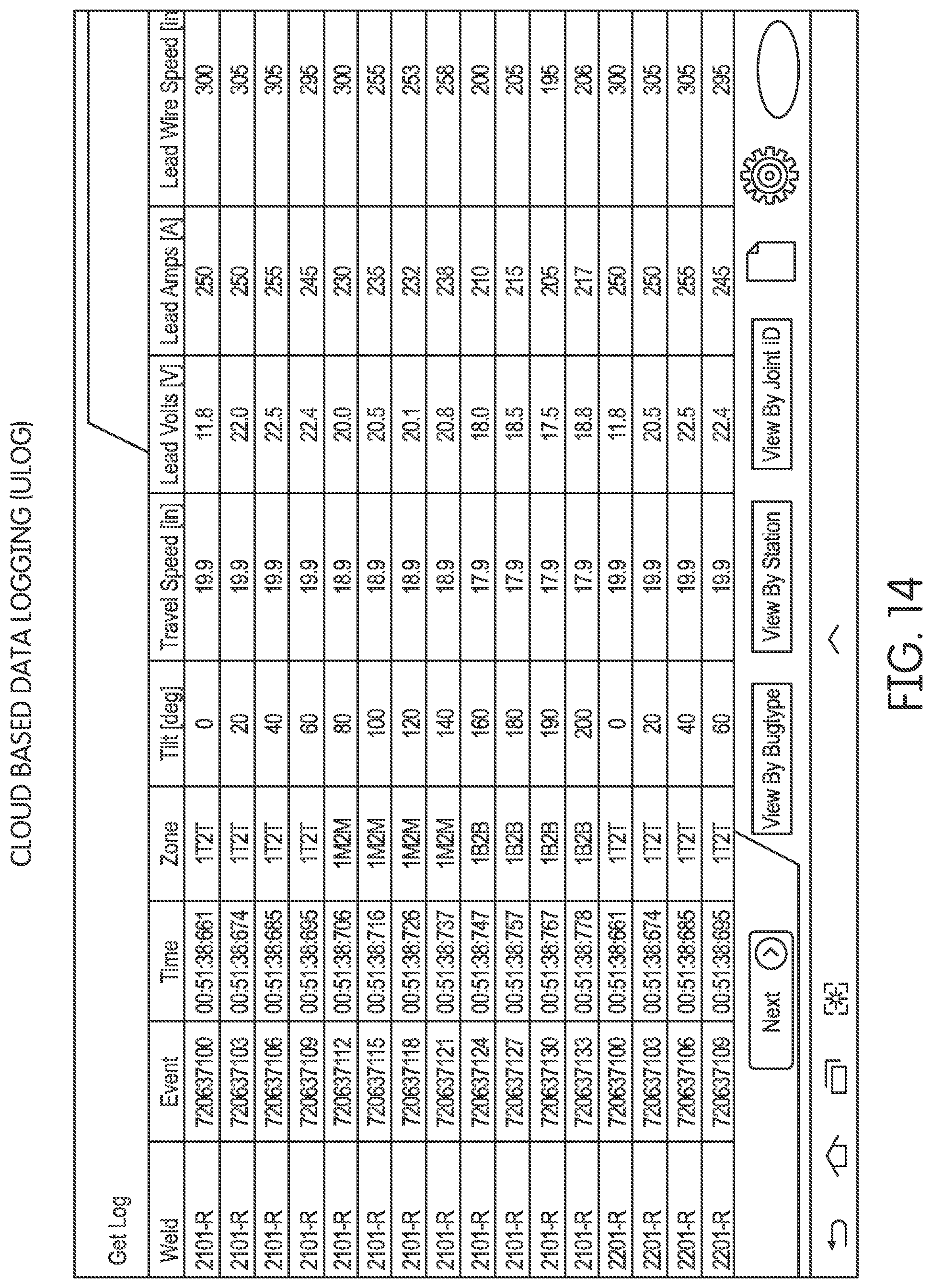
D00015

D00016

D00017

D00018

D00019

D00020
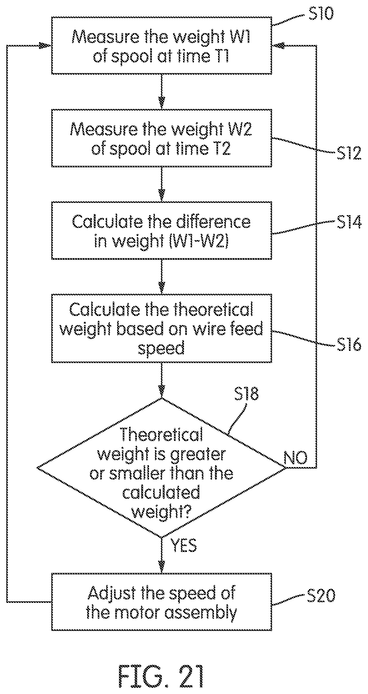
D00021
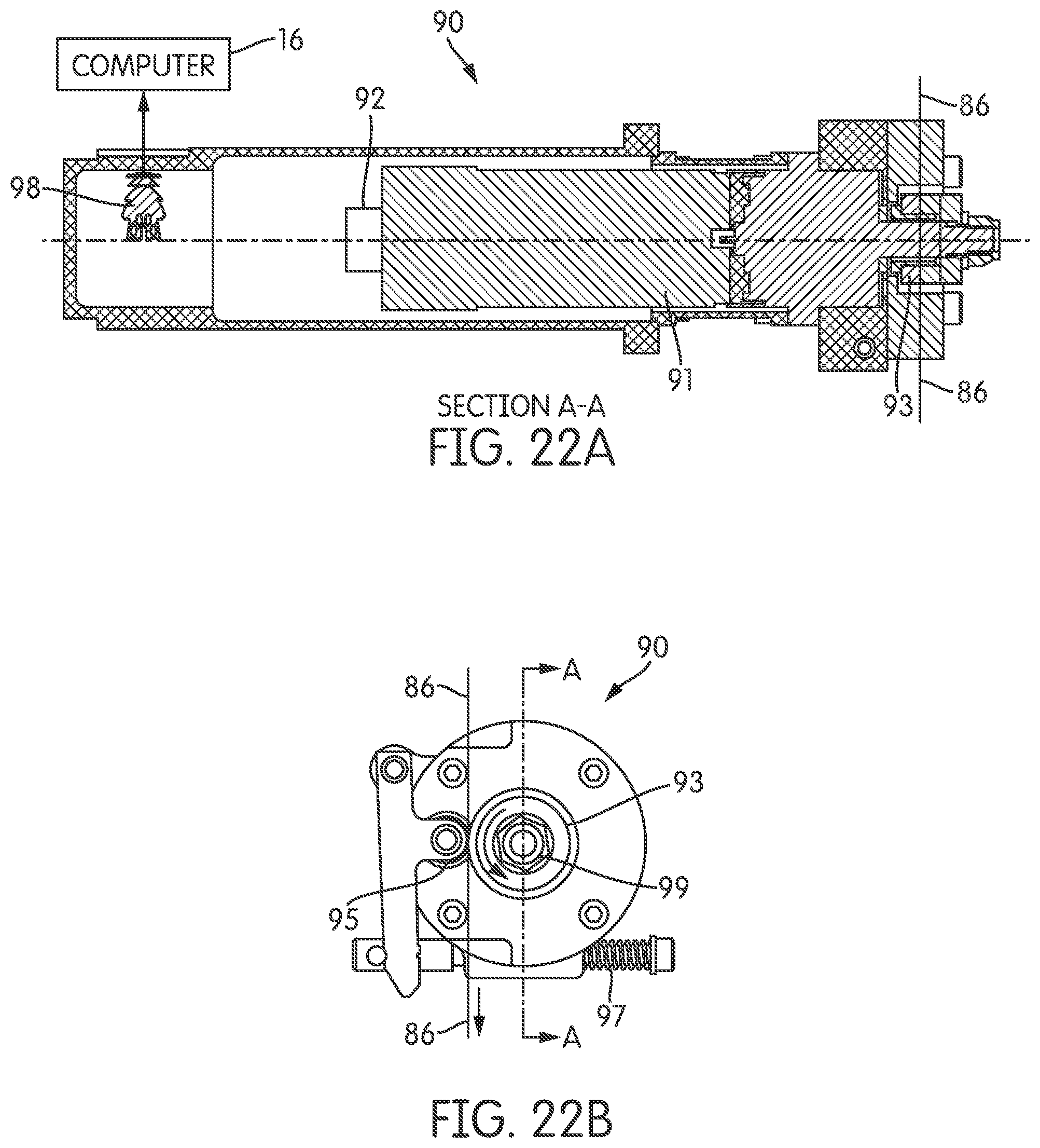
D00022

XML
uspto.report is an independent third-party trademark research tool that is not affiliated, endorsed, or sponsored by the United States Patent and Trademark Office (USPTO) or any other governmental organization. The information provided by uspto.report is based on publicly available data at the time of writing and is intended for informational purposes only.
While we strive to provide accurate and up-to-date information, we do not guarantee the accuracy, completeness, reliability, or suitability of the information displayed on this site. The use of this site is at your own risk. Any reliance you place on such information is therefore strictly at your own risk.
All official trademark data, including owner information, should be verified by visiting the official USPTO website at www.uspto.gov. This site is not intended to replace professional legal advice and should not be used as a substitute for consulting with a legal professional who is knowledgeable about trademark law.