Orthopedic device for treatment of the back
Ingimundarson , et al. November 10, 2
U.S. patent number 10,828,186 [Application Number 15/213,892] was granted by the patent office on 2020-11-10 for orthopedic device for treatment of the back. This patent grant is currently assigned to OSSUR HF. The grantee listed for this patent is OSSUR HF. Invention is credited to Arni Thor Ingimundarson, Brice Robertson.


| United States Patent | 10,828,186 |
| Ingimundarson , et al. | November 10, 2020 |
Orthopedic device for treatment of the back
Abstract
In an embodiment, an orthopedic device in the form of a lumbar support includes first and second elongate belt members, an anatomically shaped plate, and a closure system connecting the belt members to the plate. The closure system is arranged to move the belt members relative to the plate, and connects to the belt members via a flexible belt attachment which removably secures to the belt members. The closure system includes tensioning elements corresponding to the belt members, and a pulley system connecting to the tensioning elements. The closure system is slidably mounted to the plate and arranged to the belt members relative to the plate between opposed linear directions. The plate has various contours which provide pressure distribution over a lumbar region of a back. Anatomically shaped and resiliently formed handles secure to the tensioning elements and the belt members.
| Inventors: | Ingimundarson; Arni Thor (Reykjavik, IS), Robertson; Brice (Foothill Ranch, CA) | ||||||||||
|---|---|---|---|---|---|---|---|---|---|---|---|
| Applicant: |
|
||||||||||
| Assignee: | OSSUR HF (Reykjavik,
IS) |
||||||||||
| Family ID: | 1000005170935 | ||||||||||
| Appl. No.: | 15/213,892 | ||||||||||
| Filed: | July 19, 2016 |
Prior Publication Data
| Document Identifier | Publication Date | |
|---|---|---|
| US 20160324678 A1 | Nov 10, 2016 | |
Related U.S. Patent Documents
| Application Number | Filing Date | Patent Number | Issue Date | ||
|---|---|---|---|---|---|
| 14605608 | Jan 26, 2015 | 9414953 | |||
| 14215117 | Feb 3, 2015 | 8945034 | |||
| 13616130 | Jan 6, 2015 | 8926537 | |||
| 13249933 | Nov 6, 2012 | 8303528 | |||
| 12713268 | May 8, 2012 | 8172779 | |||
| 61236649 | Aug 25, 2009 | ||||
| 61155843 | Feb 26, 2009 | ||||
| Current U.S. Class: | 1/1 |
| Current CPC Class: | A61F 5/028 (20130101); A61F 2250/001 (20130101) |
| Current International Class: | A61F 5/02 (20060101) |
References Cited [Referenced By]
U.S. Patent Documents
| 7916 | January 1851 | Knapp |
| 61487 | January 1867 | Vollschwitz |
| 181948 | September 1876 | Kleinschuster |
| 232420 | September 1880 | Smith |
| 321145 | June 1885 | Spencer |
| 321146 | June 1885 | Spencer |
| 328638 | October 1885 | Battershall |
| 368699 | August 1887 | Zervas |
| 386642 | July 1888 | Mann |
| 507172 | October 1893 | Shelden |
| 571749 | November 1896 | Colton |
| 596849 | January 1898 | Combier |
| 601446 | March 1898 | Mestler |
| 616196 | December 1898 | Medbury |
| 629900 | August 1899 | Fosburgh |
| 639072 | December 1899 | Lyons |
| 664250 | December 1900 | Fitzpatrick |
| 709055 | September 1902 | Sheldon |
| 714124 | November 1902 | Adams |
| 746563 | December 1903 | McMahon |
| 772926 | October 1904 | Colton |
| 787894 | April 1905 | Colton |
| 888490 | May 1908 | Haas |
| 894066 | July 1908 | Scapra |
| 980457 | January 1911 | Toles |
| 1124596 | January 1915 | Dalpe |
| 1316915 | September 1919 | Meyer et al. |
| 1393188 | October 1921 | Whiteman |
| 1463579 | July 1923 | Funck |
| 1469661 | October 1923 | Migita |
| 1481903 | January 1924 | Hart |
| 1530713 | March 1925 | Clark |
| 1558661 | October 1925 | Yeganian |
| 1607032 | November 1926 | Whitley |
| 1755641 | April 1930 | Foulke |
| 1948785 | February 1934 | Dondelinger |
| 1981157 | November 1934 | Walter |
| 2036484 | April 1936 | Le May |
| 2100964 | November 1937 | Kendrick |
| 2117309 | May 1938 | Fritsch |
| 2219475 | October 1940 | Flaherty |
| 2409381 | October 1946 | Pease, Jr. |
| 2543370 | February 1951 | Kludt et al. |
| 2554337 | May 1951 | Lampert |
| 2630801 | March 1953 | Mest et al. |
| 2696011 | December 1954 | Galdik |
| 2749550 | June 1956 | Pease |
| 2775767 | January 1957 | Gould |
| 2793368 | May 1957 | Nouel |
| 2808050 | October 1957 | Ward |
| 2815021 | December 1957 | Freeman |
| 2828737 | April 1958 | Hale |
| 2904040 | September 1959 | Hale |
| 2906260 | September 1959 | Myers |
| 2906261 | September 1959 | Craig |
| 3095875 | July 1963 | Davidson et al. |
| 3096760 | July 1963 | Nelkin |
| 3128514 | April 1964 | Parker et al. |
| 3274996 | September 1966 | Jewett |
| 3282264 | November 1966 | Connelly |
| 3351053 | November 1967 | Stuttle |
| 3371351 | March 1968 | Allain |
| 3434469 | March 1969 | Swift |
| 3480012 | November 1969 | Smithers et al. |
| 3509875 | May 1970 | Richter |
| 3548817 | December 1970 | Mittasch |
| 3563431 | February 1971 | Pletz |
| 3570480 | March 1971 | Stubbs |
| 3578773 | May 1971 | Schultz |
| 3600717 | August 1971 | McKeehan |
| 3601819 | August 1971 | Herrmann |
| 3603316 | September 1971 | Lehman |
| 3762421 | October 1973 | Sax, Sr. |
| 3771513 | November 1973 | Velazquez |
| 3793749 | February 1974 | Gertsch et al. |
| 3808644 | May 1974 | Schoch |
| 3812850 | May 1974 | Reiman |
| 3816211 | June 1974 | Haigh |
| 3834048 | September 1974 | Maurer |
| 3889664 | June 1975 | Heuser et al. |
| 3902503 | September 1975 | Gaylord, Jr. |
| 3920008 | November 1975 | Lehman |
| 3926182 | December 1975 | Stabholz |
| 3927665 | December 1975 | Wax |
| 3945376 | March 1976 | Kuehnegger |
| 4042433 | August 1977 | Hardy et al. |
| 4055168 | October 1977 | Miller et al. |
| 4071387 | January 1978 | Schlaepfer |
| 4099524 | July 1978 | Cueman et al. |
| 4114788 | September 1978 | Zufich |
| 4162672 | July 1979 | Yazaki |
| 4173973 | November 1979 | Hendricks |
| 4175553 | November 1979 | Rosenberg |
| 4182338 | January 1980 | Stanulis |
| 4230101 | October 1980 | Gold |
| 4261081 | April 1981 | Lott |
| 4285336 | August 1981 | Oebser et al. |
| 4308861 | January 1982 | Kelly |
| 4322092 | March 1982 | Feucht et al. |
| 4383523 | May 1983 | Schurman |
| 4392489 | July 1983 | Wagner, Sr. |
| 4433456 | February 1984 | Baggio |
| RE31564 | April 1984 | Hendricks |
| 4475543 | October 1984 | Brooks et al. |
| 4479495 | October 1984 | Isaacson |
| 4494536 | January 1985 | Latenser |
| 4502471 | March 1985 | Owens |
| 4508110 | April 1985 | Modglin |
| 4531515 | July 1985 | Rolfes |
| 4555830 | December 1985 | Petrini et al. |
| 4559933 | December 1985 | Batard et al. |
| 4569336 | February 1986 | Wheeler |
| 4574500 | March 1986 | Aldinio et al. |
| 4574789 | March 1986 | Forster |
| 4574790 | March 1986 | Wellershaus |
| 4590939 | May 1986 | Sakowski |
| 4608971 | September 1986 | Borschneck |
| 4616524 | October 1986 | Bidoia |
| 4619657 | October 1986 | Keates et al. |
| 4628913 | December 1986 | Lerman |
| 4631839 | December 1986 | Bonetti et al. |
| 4631840 | December 1986 | Gamm |
| 4635626 | January 1987 | Lerman |
| 4640269 | February 1987 | Goins |
| 4648390 | March 1987 | Friddle |
| 4649574 | March 1987 | Michels |
| 4654985 | April 1987 | Chalmers |
| 4655201 | April 1987 | Pirmantgen |
| 4658807 | April 1987 | Swain |
| 4660302 | April 1987 | Arieh et al. |
| 4677699 | July 1987 | Barabe |
| 4677969 | July 1987 | Calabrese |
| 4680878 | July 1987 | Pozzobon et al. |
| 4691696 | September 1987 | Farfan De Los Godos |
| 4696291 | September 1987 | Tyo |
| 4697583 | October 1987 | Mason et al. |
| 4697592 | October 1987 | Maddux et al. |
| 4716898 | January 1988 | Chauve et al. |
| 4719670 | January 1988 | Kurt |
| 4719709 | January 1988 | Vaccari |
| 4761834 | August 1988 | Kolb |
| 4796610 | January 1989 | Cromartie |
| 4799297 | January 1989 | Baggio et al. |
| 4802291 | February 1989 | Sartor |
| 4805605 | February 1989 | Glassman |
| 4807605 | February 1989 | Mattingly |
| 4811503 | March 1989 | Iwama |
| 4843688 | July 1989 | Ikeda |
| 4862878 | September 1989 | Davison et al. |
| 4870761 | October 1989 | Tracy |
| 4905678 | March 1990 | Cumins et al. |
| 4923474 | May 1990 | Klasson et al. |
| 4937952 | July 1990 | Olivieri |
| 4961544 | October 1990 | Bidoia |
| 4963208 | October 1990 | Muncy et al. |
| 4976257 | December 1990 | Akin et al. |
| 4986263 | January 1991 | Dickerson et al. |
| 4997438 | March 1991 | Nipper |
| 5027482 | July 1991 | Torppey |
| 5072725 | December 1991 | Miller |
| 5074288 | December 1991 | Miller |
| 5092321 | March 1992 | Spademan |
| 5098770 | March 1992 | Paire |
| 5105828 | April 1992 | Grant |
| 5111807 | May 1992 | Spahn et al. |
| 5117567 | June 1992 | Berger |
| 5120288 | June 1992 | Sinaki |
| 5121741 | June 1992 | Bremer et al. |
| 5127897 | July 1992 | Roller |
| 5135470 | August 1992 | Reeves |
| 5135471 | August 1992 | Houswerth |
| 5154690 | October 1992 | Shiono |
| 5157813 | October 1992 | Carroll |
| 5170505 | December 1992 | Rohrer |
| 5171296 | December 1992 | Herman |
| 5176131 | January 1993 | Votel et al. |
| 5177882 | January 1993 | Berger |
| 5181331 | January 1993 | Berger |
| 5183036 | February 1993 | Spademan |
| D334063 | March 1993 | Dewall |
| 5199940 | April 1993 | Morris et al. |
| 5201074 | April 1993 | Dicker |
| 5203765 | April 1993 | Friddle, Jr. |
| 5215518 | June 1993 | Rosen |
| 5226874 | July 1993 | Heinz et al. |
| 5230698 | July 1993 | Garth |
| 5259831 | November 1993 | Lebron |
| 5259833 | November 1993 | Barnett |
| 5267928 | December 1993 | Barile et al. |
| 5295947 | March 1994 | Muncy |
| 5295996 | March 1994 | Blair |
| 5307521 | May 1994 | Davis |
| 5313952 | May 1994 | Hoch |
| 5318575 | June 1994 | Chesterfield et al. |
| 5327662 | July 1994 | Hallenbeck |
| 5334135 | August 1994 | Grim et al. |
| 5342289 | August 1994 | Munny |
| 5346461 | September 1994 | Heinz et al. |
| 5363863 | November 1994 | Lelli et al. |
| 5365947 | November 1994 | Bonutti |
| 5368552 | November 1994 | Williamson et al. |
| 5376129 | December 1994 | Faulkner et al. |
| 5383893 | January 1995 | Daneshvar |
| 5387245 | February 1995 | Fay et al. |
| 5399151 | March 1995 | Smith |
| 5421809 | June 1995 | Rise |
| 5423852 | June 1995 | Daneshvar |
| 5429587 | July 1995 | Gates |
| 5433648 | July 1995 | Frydman |
| 5433697 | July 1995 | Cox |
| 5435015 | July 1995 | Ellis-Brewer |
| 5437614 | August 1995 | Grim |
| 5437617 | August 1995 | Heinz et al. |
| 5437619 | August 1995 | Malewicz et al. |
| 5449338 | September 1995 | Trudell |
| 5450858 | September 1995 | Zablotsky et al. |
| 5466214 | November 1995 | Calderon-Garciduenas |
| 5484395 | January 1996 | Deroche |
| 5499965 | March 1996 | Sanchez |
| 5500959 | March 1996 | Yewer, Jr. |
| 5502902 | April 1996 | Sussmann |
| 5503314 | April 1996 | Fiscus |
| 5503620 | April 1996 | Danzger |
| 5507681 | April 1996 | Smith et al. |
| 5507834 | April 1996 | Laghi |
| 5520619 | May 1996 | Martin |
| 5522792 | June 1996 | Bassett et al. |
| 5531669 | July 1996 | Varnau |
| 5536246 | July 1996 | Saunders |
| 5539020 | July 1996 | Bracken et al. |
| 5548843 | August 1996 | Chase et al. |
| 5551950 | September 1996 | Oppen |
| 5556374 | September 1996 | Grace et al. |
| 5558628 | September 1996 | Bzoch |
| 5569171 | October 1996 | Muncy |
| 5571355 | November 1996 | Kornylo |
| 5599287 | February 1997 | Beczak, Sr. et al. |
| 5599288 | February 1997 | Shirley et al. |
| 5603122 | February 1997 | Kania |
| 5620412 | April 1997 | Modglin |
| 5622529 | April 1997 | Calabrese |
| 5632724 | May 1997 | Lerman et al. |
| 5634891 | June 1997 | Beczak, Sr. et al. |
| 5638588 | June 1997 | Jungkind |
| 5669116 | September 1997 | Jungkind |
| 5674187 | October 1997 | Zepf |
| 5681270 | October 1997 | Klearman et al. |
| 5685830 | November 1997 | Bonutti |
| 5685831 | November 1997 | Floyd |
| 5688137 | November 1997 | Bustance |
| 5690260 | November 1997 | Aikins et al. |
| 5690609 | November 1997 | Heinze, III |
| 5695452 | December 1997 | Grim et al. |
| 5695520 | December 1997 | Bruckner et al. |
| 5704904 | January 1998 | Dunfee |
| 5704937 | January 1998 | Martin |
| 5708977 | January 1998 | Morkunas |
| 5718670 | February 1998 | Bremer |
| 5722940 | March 1998 | Gaylord, Jr. et al. |
| 5724993 | March 1998 | Dunfee |
| 5725139 | March 1998 | Smith |
| 5728054 | March 1998 | Martin |
| 5728168 | March 1998 | Laghi et al. |
| 5732483 | March 1998 | Cagliari |
| 5735807 | April 1998 | Cropper |
| 5737854 | April 1998 | Sussmann |
| 5746218 | May 1998 | Edge |
| 5752640 | May 1998 | Proulx |
| 5778565 | July 1998 | Holt et al. |
| 5782782 | July 1998 | Miller |
| 5795316 | August 1998 | Gaylord |
| RE35940 | October 1998 | Heinz et al. |
| 5816251 | October 1998 | Glisan |
| 5819378 | October 1998 | Doyle |
| 5823981 | October 1998 | Grim et al. |
| 5826766 | October 1998 | Aftanas |
| 5827211 | October 1998 | Sellinger |
| 5830167 | November 1998 | Jung |
| 5836493 | November 1998 | Grunsted et al. |
| 5840050 | November 1998 | Lerman |
| 5840051 | November 1998 | Towsley |
| 5848979 | December 1998 | Bonutti et al. |
| 5853378 | December 1998 | Modglin |
| 5853379 | December 1998 | Ostojic |
| 5857988 | January 1999 | Shirley |
| 5868292 | February 1999 | Stephens et al. |
| 5890640 | April 1999 | Thompson |
| 5891061 | April 1999 | Kaiser |
| 5893871 | April 1999 | Tanaka |
| 5911697 | June 1999 | Biedermann et al. |
| 5916070 | June 1999 | Donohue |
| 5938629 | August 1999 | Bloedau |
| 5950628 | September 1999 | Dunfee |
| 5954250 | September 1999 | Hall et al. |
| 5954253 | September 1999 | Swetish |
| 5967998 | October 1999 | Modglin |
| 5968002 | October 1999 | Morrisseau |
| 5993403 | November 1999 | Martin |
| 6007503 | December 1999 | Berger et al. |
| 6010472 | January 2000 | Schiller |
| 6027466 | February 2000 | Diefenbacher et al. |
| 6029273 | February 2000 | McCrane |
| 6036664 | March 2000 | Martin, Sr. et al. |
| 6039707 | March 2000 | Crawford et al. |
| 6063047 | May 2000 | Minne |
| 6066108 | May 2000 | Lundberg |
| 6070776 | June 2000 | Furnary et al. |
| 6090057 | July 2000 | Collins et al. |
| 6099490 | August 2000 | Turtzo |
| 6110138 | August 2000 | Shirley |
| 6117096 | September 2000 | Hassard |
| RE36905 | October 2000 | Noble et al. |
| 6125792 | October 2000 | Gee |
| 6129638 | October 2000 | Davis |
| 6129691 | October 2000 | Ruppert |
| 6156001 | December 2000 | Frangi et al. |
| 6159248 | December 2000 | Gramnas |
| 6182288 | February 2001 | Kibbee |
| 6189538 | February 2001 | Thorpe |
| 6190343 | February 2001 | Heinz et al. |
| D438624 | March 2001 | Reina |
| 6206932 | March 2001 | Johnson |
| 6213968 | April 2001 | Heinz et al. |
| 6227937 | May 2001 | Principe |
| 6245033 | June 2001 | Martin |
| 6254561 | July 2001 | Borden |
| 6256798 | July 2001 | Egolf et al. |
| 6267390 | July 2001 | Maravetz et al. |
| 6282729 | September 2001 | Oikawa et al. |
| 6289558 | September 2001 | Hammerslag |
| 6315746 | November 2001 | Garth et al. |
| 6322529 | November 2001 | Chung |
| 6325023 | December 2001 | Elnatan |
| 6338723 | January 2002 | Carpenter et al. |
| 6375632 | April 2002 | Albrecht et al. |
| 6401786 | June 2002 | Tedeschi et al. |
| 6413232 | July 2002 | Townsend et al. |
| 6416074 | July 2002 | Maravetz et al. |
| 6419652 | July 2002 | Slautterback |
| 6425876 | July 2002 | Frangi et al. |
| 6428493 | August 2002 | Pior et al. |
| 6432073 | August 2002 | Pior et al. |
| 6471665 | October 2002 | Milbourn et al. |
| 6478759 | November 2002 | Modglin et al. |
| 6494853 | December 2002 | Rossi et al. |
| 6502577 | January 2003 | Bonutti |
| 6503213 | January 2003 | Bonutti |
| 6517502 | February 2003 | Heyman et al. |
| 6540703 | April 2003 | Lerman |
| 6589195 | July 2003 | Schwenn et al. |
| 6602214 | August 2003 | Heinz et al. |
| 6605052 | August 2003 | Cool et al. |
| 6609642 | August 2003 | Heinz et al. |
| 6623419 | September 2003 | Smith et al. |
| 6652596 | November 2003 | Smith et al. |
| 6656144 | December 2003 | Coligado |
| 6676617 | January 2004 | Miller |
| 6676620 | January 2004 | Schwenn |
| 6688943 | February 2004 | Nagaoka |
| 6689080 | February 2004 | Castillo |
| 6702770 | March 2004 | Bremer et al. |
| 6711750 | March 2004 | Yoo |
| 6711787 | March 2004 | Jungkind et al. |
| 6726643 | April 2004 | Martin |
| 6769155 | August 2004 | Hess et al. |
| 6770047 | August 2004 | Bonutti |
| 6773411 | August 2004 | Alvarez |
| 6790191 | September 2004 | Hendricks |
| 6802442 | October 2004 | Thompson |
| D499806 | December 2004 | Machin et al. |
| 6827653 | December 2004 | Be |
| D501078 | January 2005 | Cabana |
| 6893098 | May 2005 | Kohani |
| 6893411 | May 2005 | Modglin |
| 6913585 | July 2005 | Salmon et al. |
| 6921375 | July 2005 | Kihara |
| 6921377 | July 2005 | Bonutti |
| 6923780 | August 2005 | Price et al. |
| 6926685 | August 2005 | Modglin |
| 6936021 | August 2005 | Smith |
| 6942630 | September 2005 | Behan |
| 6951547 | October 2005 | Park et al. |
| 6962572 | November 2005 | Zahiri |
| 6964644 | November 2005 | Garth |
| 6991611 | January 2006 | Rhee |
| 7001348 | February 2006 | Garth et al. |
| 7001350 | February 2006 | Grosso |
| 7025737 | April 2006 | Modglin |
| 7028873 | April 2006 | Collier et al. |
| 7034251 | April 2006 | Child et al. |
| 7048707 | May 2006 | Schwenn et al. |
| 7074204 | July 2006 | Fujii et al. |
| 7083584 | August 2006 | Coligado |
| 7083585 | August 2006 | Latham |
| 7087032 | August 2006 | Ikeda |
| 7101348 | September 2006 | Garth et al. |
| 7118543 | October 2006 | Telles et al. |
| 7128724 | October 2006 | Marsh |
| 7134224 | November 2006 | Elkington et al. |
| 7137973 | November 2006 | Plauche et al. |
| 7140691 | November 2006 | Kohani |
| 7166083 | January 2007 | Bledsoe |
| 7186229 | March 2007 | Schwenn et al. |
| 7198610 | April 2007 | Ingimundarson et al. |
| 7201727 | April 2007 | Schwenn et al. |
| 7235059 | June 2007 | Mason et al. |
| 7281341 | October 2007 | Reagan et al. |
| 7306571 | December 2007 | Schwenn et al. |
| 7306573 | December 2007 | Bonutti |
| 7309304 | December 2007 | Stewart et al. |
| 7316660 | January 2008 | Modglin |
| 7320670 | January 2008 | Modglin |
| 7322950 | January 2008 | Modglin |
| 7329231 | February 2008 | Frank |
| 7331126 | February 2008 | Johnson |
| 7351368 | April 2008 | Abrams |
| 7389547 | June 2008 | Wiens |
| 7402147 | July 2008 | Allen |
| 7404804 | July 2008 | Bonutti |
| 7416565 | August 2008 | Al-Turaikl |
| 7438698 | October 2008 | Daiju |
| 7473235 | January 2009 | Schwenn et al. |
| 7476185 | January 2009 | Drennan |
| 7513018 | April 2009 | Koenig et al. |
| 7549970 | June 2009 | Tweardy |
| 7578798 | August 2009 | Rhee |
| 7591050 | September 2009 | Hammerslag |
| 7597671 | October 2009 | Baumgartner et al. |
| 7597672 | October 2009 | Kruijsen et al. |
| 7600660 | October 2009 | Kasper et al. |
| 7615021 | November 2009 | Nordt, III et al. |
| 7618386 | November 2009 | Nordt, III et al. |
| 7618389 | November 2009 | Nordt, III et al. |
| 7654972 | February 2010 | Alleyne |
| 7662121 | February 2010 | Zours |
| 7670306 | March 2010 | Nordt, III et al. |
| 7682219 | March 2010 | Falla |
| 7699797 | April 2010 | Nordt, III et al. |
| 7704219 | April 2010 | Nordt, III et al. |
| 7727048 | June 2010 | Gransberry |
| 7727174 | June 2010 | Chang et al. |
| 7757307 | July 2010 | Wong |
| 7775999 | August 2010 | Brown |
| 7806842 | October 2010 | Stevenson et al. |
| 7815585 | October 2010 | Vollbrecht |
| 7819831 | October 2010 | Dellanno |
| 7833182 | November 2010 | Hughes |
| 7842000 | November 2010 | Lai et al. |
| 7857776 | December 2010 | Frisbie |
| 7862529 | January 2011 | Brown |
| 7862621 | January 2011 | Kloos et al. |
| 7871388 | January 2011 | Brown |
| 7878998 | February 2011 | Nordt, III et al. |
| 7887500 | February 2011 | Nordt, III et al. |
| 7914473 | March 2011 | Josey |
| D636494 | April 2011 | Garth et al. |
| 7922680 | April 2011 | Nordt, III et al. |
| 7950112 | May 2011 | Hammerslag et al. |
| 7954204 | June 2011 | Hammerslag et al. |
| 7959591 | June 2011 | Powers et al. |
| 7993296 | August 2011 | Nordt, III et al. |
| 8002724 | August 2011 | Hu et al. |
| 8006877 | August 2011 | Lowry et al. |
| 8038635 | October 2011 | Dellanno |
| 8038637 | October 2011 | Bonutti |
| 8047893 | November 2011 | Fenske |
| 8048014 | November 2011 | Brown |
| 8066161 | November 2011 | Green et al. |
| 8066654 | November 2011 | Sandifer et al. |
| 8091182 | January 2012 | Hammerslag et al. |
| 8142377 | March 2012 | Garth et al. |
| 8162194 | April 2012 | Gleason |
| 8162864 | April 2012 | Kruijsen et al. |
| 8172779 | May 2012 | Ingimundarson et al. |
| 8214926 | July 2012 | Brown |
| 8216167 | July 2012 | Garth et al. |
| 8303528 | November 2012 | Ingimundarson et al. |
| 8308669 | November 2012 | Nace |
| 8308670 | November 2012 | Sandifer et al. |
| 8308869 | November 2012 | Gardner et al. |
| 8372023 | February 2013 | Garth et al. |
| 8381314 | February 2013 | Takamoto et al. |
| 8556840 | October 2013 | Burke et al. |
| 8597222 | December 2013 | Lucero et al. |
| 8657769 | February 2014 | Ingimundarson et al. |
| 8728019 | May 2014 | Kruijsen et al. |
| 8795215 | August 2014 | Rossi |
| 8893312 | November 2014 | Takamoto et al. |
| 9370440 | June 2016 | Ingimundarson et al. |
| 9468554 | October 2016 | Petursson et al. |
| 9554935 | January 2017 | Ingimundarson et al. |
| 9572705 | February 2017 | Ingimundarson et al. |
| 9795500 | October 2017 | Ingimundarson et al. |
| 2001/0020144 | September 2001 | Heinz et al. |
| 2001/0031936 | October 2001 | Pior et al. |
| 2002/0032397 | March 2002 | Coligado |
| 2002/0068890 | June 2002 | Schwenn et al. |
| 2002/0148461 | October 2002 | Heinz et al. |
| 2002/0158097 | October 2002 | Beale |
| 2003/0000986 | January 2003 | Smith |
| 2003/0028952 | February 2003 | Fujii et al. |
| 2003/0125650 | July 2003 | Grosso |
| 2003/0125705 | July 2003 | Ruman et al. |
| 2003/0139698 | July 2003 | Hyson |
| 2003/0220594 | November 2003 | Halvorson et al. |
| 2003/0229301 | December 2003 | Coligado |
| 2004/0024340 | February 2004 | Schwenn et al. |
| 2004/0050391 | March 2004 | Kiwala et al. |
| 2004/0082895 | April 2004 | Price et al. |
| 2004/0097857 | May 2004 | Reinecke et al. |
| 2004/0108350 | June 2004 | Warren |
| 2004/0116260 | June 2004 | Drennan |
| 2004/0132380 | July 2004 | Kihara |
| 2004/0133138 | July 2004 | Modglin |
| 2004/0143204 | July 2004 | Salmon et al. |
| 2004/0162582 | August 2004 | Banziger |
| 2004/0254505 | December 2004 | Begley et al. |
| 2005/0054960 | March 2005 | Telles et al. |
| 2005/0059917 | March 2005 | Garth et al. |
| 2005/0067816 | March 2005 | Buckman |
| 2005/0081339 | April 2005 | Sakabayashi |
| 2005/0131323 | June 2005 | Bledsoe |
| 2005/0137508 | June 2005 | Miller |
| 2005/0154337 | July 2005 | Meyer |
| 2005/0160627 | July 2005 | Dalgaard et al. |
| 2005/0165338 | July 2005 | Iglesias et al. |
| 2005/0228325 | October 2005 | Zours et al. |
| 2005/0240134 | October 2005 | Brown |
| 2005/0251074 | November 2005 | Latham |
| 2005/0267390 | December 2005 | Garth et al. |
| 2005/0273025 | December 2005 | Houser |
| 2006/0000478 | January 2006 | Taylor |
| 2006/0011690 | January 2006 | Bareno |
| 2006/0052733 | March 2006 | Schwenn et al. |
| 2006/0064048 | March 2006 | Stano |
| 2006/0074365 | April 2006 | Brown |
| 2006/0079821 | April 2006 | Rauch |
| 2006/0129077 | June 2006 | Parizot |
| 2006/0135900 | June 2006 | Ingimundarson et al. |
| 2006/0135901 | June 2006 | Ingimundarson et al. |
| 2006/0135903 | June 2006 | Ingimundarson et al. |
| 2006/0155229 | July 2006 | Ceriani et al. |
| 2006/0156517 | July 2006 | Hammerslag et al. |
| 2006/0206992 | September 2006 | Godshaw et al. |
| 2006/0254598 | November 2006 | Saul |
| 2006/0260620 | November 2006 | Kazerooni et al. |
| 2007/0152007 | July 2007 | Kauss et al. |
| 2007/0167895 | July 2007 | Gramza et al. |
| 2007/0179417 | August 2007 | Schwenn et al. |
| 2007/0185425 | August 2007 | Einarsson et al. |
| 2008/0045873 | February 2008 | Zours |
| 2008/0091132 | April 2008 | Bonutti |
| 2008/0195010 | August 2008 | Lai et al. |
| 2008/0208090 | August 2008 | Vollbrecht |
| 2008/0208091 | August 2008 | Vollbrecht et al. |
| 2008/0249448 | October 2008 | Stevenson et al. |
| 2008/0262401 | October 2008 | Wagner et al. |
| 2008/0302839 | December 2008 | Murdoch et al. |
| 2008/0319362 | December 2008 | Joseph |
| 2009/0025115 | January 2009 | Duffy et al. |
| 2009/0030353 | January 2009 | Bonutti et al. |
| 2009/0030359 | January 2009 | Wikenheiser et al. |
| 2009/0062704 | March 2009 | Brown et al. |
| 2009/0082707 | March 2009 | Rumsey |
| 2009/0100649 | April 2009 | Bar et al. |
| 2009/0124948 | May 2009 | Ingimundarson et al. |
| 2009/0127308 | May 2009 | Mori et al. |
| 2009/0182253 | July 2009 | Grim et al. |
| 2009/0192425 | July 2009 | Garth et al. |
| 2009/0198166 | August 2009 | Shlomovitz |
| 2009/0275871 | November 2009 | Liu |
| 2009/0287128 | November 2009 | Ingimundarson et al. |
| 2010/0010568 | January 2010 | Brown |
| 2010/0037369 | February 2010 | Reichert |
| 2010/0139057 | June 2010 | Soderberg et al. |
| 2010/0204630 | August 2010 | Sandifer et al. |
| 2010/0205713 | August 2010 | Takamoto et al. |
| 2010/0217167 | August 2010 | Ingimundarson et al. |
| 2010/0228170 | September 2010 | Imai |
| 2010/0256717 | October 2010 | Brown |
| 2010/0268139 | October 2010 | Garth |
| 2010/0268141 | October 2010 | Bannister |
| 2010/0274364 | October 2010 | Pacanowsky et al. |
| 2010/0292622 | November 2010 | Weissleder et al. |
| 2010/0299959 | December 2010 | Hammerslag et al. |
| 2010/0318010 | December 2010 | Sandifer et al. |
| 2011/0000005 | January 2011 | Brown |
| 2011/0009793 | January 2011 | Lucero et al. |
| 2011/0046528 | February 2011 | Stevenson et al. |
| 2011/0082402 | April 2011 | Oddou et al. |
| 2011/0098618 | April 2011 | Fleming |
| 2011/0105971 | May 2011 | Ingimundarson et al. |
| 2011/0137221 | June 2011 | Brown |
| 2011/0144551 | June 2011 | Johnson |
| 2011/0152737 | June 2011 | Burke et al. |
| 2011/0178448 | July 2011 | Einarsson |
| 2011/0184326 | July 2011 | Ingimundarson et al. |
| 2011/0266384 | November 2011 | Goodman et al. |
| 2012/0010547 | January 2012 | Hinds |
| 2012/0022420 | January 2012 | Sandifer et al. |
| 2012/0029404 | February 2012 | Weaver, II et al. |
| 2012/0078151 | March 2012 | Cropper |
| 2012/0197167 | August 2012 | Kruijsen et al. |
| 2012/0204381 | August 2012 | Ingimundarson et al. |
| 2012/0220910 | August 2012 | Gaylord et al. |
| 2012/0232450 | September 2012 | Garth et al. |
| 2012/0245502 | November 2012 | Garth et al. |
| 2012/0323154 | December 2012 | Ingimundarson et al. |
| 2013/0006158 | January 2013 | Ingimundarson et al. |
| 2013/0007946 | January 2013 | Brown |
| 2013/0012853 | January 2013 | Brown |
| 2013/0158457 | June 2013 | Garth et al. |
| 2013/0174326 | July 2013 | Takamoto et al. |
| 2013/0184628 | July 2013 | Ingimundarson et al. |
| 2013/0190670 | July 2013 | Von Zieglauer |
| 2013/0211302 | August 2013 | Brown |
| 2013/0237891 | September 2013 | Fryman et al. |
| 2013/0281901 | October 2013 | Ochoa |
| 2013/0298914 | November 2013 | Shibaya et al. |
| 2014/0081189 | March 2014 | Ingimundarson et al. |
| 2014/0116452 | May 2014 | Ingimundarson et al. |
| 2014/0207040 | June 2014 | Ingimundarson et al. |
| 2014/0200121 | July 2014 | Von Hoffmann et al. |
| 2014/0207041 | July 2014 | Ingimundarson et al. |
| 2014/0336020 | November 2014 | Von Hoffmann et al. |
| 2016/0228279 | August 2016 | Modglin et al. |
| 2016/0250061 | September 2016 | Ingimundarson et al. |
| 20 1027 10 20 | Feb 2012 | AU | |||
| 20 1027 10 20 | Feb 2012 | AU | |||
| 20 1028 68 51 | Mar 2012 | AU | |||
| 20 1028 68 51 | May 2012 | AU | |||
| 2 112 789 | Aug 1994 | CA | |||
| 2 114 387 | Aug 1994 | CA | |||
| 2 767 353 | Jan 2011 | CA | |||
| 2 772 296 | Mar 2011 | CA | |||
| 577 282 | Jul 1976 | CH | |||
| 612 076 | Jul 1979 | CH | |||
| 624 001 | Jul 1981 | CH | |||
| 1311648 | Sep 2001 | CN | |||
| 1383799 | Dec 2002 | CN | |||
| 1461190 | Dec 2003 | CN | |||
| 101219079 | Jul 2008 | CN | |||
| 201101603 | Aug 2008 | CN | |||
| 101444443 | Jun 2009 | CN | |||
| 101820783 | Sep 2010 | CN | |||
| 102470040 | May 2012 | CN | |||
| 1 197 192 | Jul 1965 | DE | |||
| 88 04 683 | Jun 1988 | DE | |||
| 38 22 113 | Jan 1990 | DE | |||
| 94 17 221 | Jan 1995 | DE | |||
| 93 15 776 | Feb 1995 | DE | |||
| 295 03 552 | Apr 1995 | DE | |||
| 199 45 045 | Mar 2001 | DE | |||
| 202 04 747 | Jul 2002 | DE | |||
| 103 29 454 | Jan 2005 | DE | |||
| 20 2004 015 328 | Feb 2005 | DE | |||
| 20 2005 007 124 | Jun 2005 | DE | |||
| 10 2005 017 587 | Apr 2006 | DE | |||
| 20 2009 004 817 | Sep 2010 | DE | |||
| 202009004817 | Sep 2010 | DE | |||
| 0 393 380 | Sep 1992 | EP | |||
| 0 589 233 | Mar 1994 | EP | |||
| 0 614 624 | Sep 1994 | EP | |||
| 0 614 625 | Sep 1994 | EP | |||
| 0 657 149 | Jun 1995 | EP | |||
| 0 589 232 | Nov 1995 | EP | |||
| 0 693 260 | Sep 1998 | EP | |||
| 0 651 954 | Feb 1999 | EP | |||
| 1 159 940 | Dec 2001 | EP | |||
| 1 236 412 | Sep 2002 | EP | |||
| 1 342 423 | Sep 2003 | EP | |||
| 1 588 678 | Oct 2005 | EP | |||
| 1 743 608 | Jan 2007 | EP | |||
| 1 985 264 | Oct 2008 | EP | |||
| 2 200 545 | Jun 2010 | EP | |||
| 2 451 412 | May 2012 | EP | |||
| 2 473 072 | Jul 2012 | EP | |||
| 1 104 562 | Nov 1955 | FR | |||
| 2 757 073 | Jun 1998 | FR | |||
| 2 952 807 | May 2011 | FR | |||
| 826 041 | Dec 1959 | GB | |||
| 909 970 | Nov 1962 | GB | |||
| 2 133 289 | Jul 1984 | GB | |||
| H07-246212 | Sep 1995 | JP | |||
| 3031760 | Dec 1996 | JP | |||
| H09-273582 | Oct 1997 | JP | |||
| H10-237708 | Sep 1998 | JP | |||
| 2000-290331 | Oct 2000 | JP | |||
| 2001-204851 | Jul 2001 | JP | |||
| 3091470 | Jan 2003 | JP | |||
| 2003-175063 | Jun 2003 | JP | |||
| 2004-016732 | Jan 2004 | JP | |||
| 2004-041666 | Feb 2004 | JP | |||
| 2004-160075 | Jun 2004 | JP | |||
| 2004-209050 | Jul 2004 | JP | |||
| 2007-291536 | Nov 2007 | JP | |||
| 3142546 | Jun 2008 | JP | |||
| 2008-178618 | Aug 2008 | JP | |||
| 2009-082697 | Apr 2009 | JP | |||
| 2012-011550 | Jan 2012 | JP | |||
| 2013-503268 | Jan 2013 | JP | |||
| 2013-536010 | Sep 2013 | JP | |||
| 94/01496 | Jan 1994 | WO | |||
| 95/03720 | Feb 1995 | WO | |||
| 97/03581 | Feb 1997 | WO | |||
| 00/53045 | Sep 2000 | WO | |||
| 2004/110197 | Dec 2004 | WO | |||
| 2005/086752 | Apr 2005 | WO | |||
| 2005/086752 | Sep 2005 | WO | |||
| 2006/121413 | Nov 2006 | WO | |||
| 2007003148 | Jan 2007 | WO | |||
| 2009/017499 | Feb 2009 | WO | |||
| 2009/017949 | Feb 2009 | WO | |||
| 2009/052031 | Apr 2009 | WO | |||
| 2009/068503 | Jun 2009 | WO | |||
| 2010/141958 | Dec 2010 | WO | |||
| 2011/005430 | Jan 2011 | WO | |||
| 2011/025675 | Mar 2011 | WO | |||
| 2011066323 | Jun 2011 | WO | |||
| 2012/029917 | Mar 2012 | WO | |||
| 2013-016670 | Jan 2013 | WO | |||
| 2016138215 | Sep 2016 | WO | |||
Other References
|
Pamphlet--"Bledsoe Phillippon K.A.F. Positioning Kit, Application Instructions (CP020205 Rev B 04/07), New Hip Arthroscopy Padding and Positioning Kit", Council Directive 93/42/EEC of Jun. 14, 1993 concerning Medical Devices, 2 pages. cited by applicant . Mehlman, Charles T. et al., "Hyphenated History: Knight-Taylor Spinal Orthosis"; American Journal of Orthopedics; Jun. 2000; pp. 479-483, vol. 29, Issue 6. cited by applicant . Pamphlet--"Bledsoe Phillippon K.A.F. Positioning Kit", Bledsoe Brace Systems, Medical Technology Inc., 2004, 2 pages. cited by applicant . Posture Control Brace. Soft Form, Orthopaedic by Design, FLA Orthopedics, Inc., 1 page; 2004. http://www.flaorthopedics.com. cited by applicant . Michael Pfiefer, MD et al., "Effects of a New Spinal Orthosis on Posture, Trunk Strength, and Quality of Life in Women with Postmenopausal Osteoporosis--a Randomized Trial", American Journal of Physical Medicine & Rehabilitation, vol. 83, No. 3, Mar. 2004, USA, pp. 177-186. cited by applicant . Scoliosis Specialists. About the SpineCor Brace; 2006-2012; http://www.scoliosisspecialists.com/aboutspinecorbrace.html. Retrieved from Internet on Aug. 1, 2013. cited by applicant . Hsu et al., "Principles and Components of Spinal Orthoses", AAOS Atlas of Orthoses and Assistive Devices, 4th Ed., Chapter 7, 2008, pp. 89-111. cited by applicant . International Search Report and Written Opinion from Corresponding to International Application No. PCT/US2010/002893, dated Feb. 22, 2011. cited by applicant . International Search Report from PCT Application No. PCT/US2010/000601, dated Jun. 28, 2010. cited by applicant . International Preliminary Report on Patentability from PCT Application No. PCT/US2010/000601, dated Aug. 30, 2011. cited by applicant . Bledsoe Products, "Philippon K.A.F. Positioning Kit". Http://bledsoebrace.com/products/kaf.asp [retrieve from the internet May 10, 2012]. cited by applicant . International Search Report and Written Opinion Issued in PCT/2012/024619, dated May 16, 2012. cited by applicant . International Search Report and Written Opinon of the International Searching Authority Issued in PCT/US2012/043252, dated Jan. 10, 2013. cited by applicant . International Search Report from Corresponding PCT Application No. PCT/US2013/021170 dated Apr. 12, 2013. cited by applicant . Spinomed Brochure--Spinal Orthosis for Vertebral Extension in Osteoporosis; Stellar Orthotics and Prosthetics Group, 2 pages, retrieved from Internet Sep. 23, 2013. http://www.stellaroandp.com/spotlight.html. cited by applicant . Sato, Ena et al., "Effect of the WISH-type hip brace on functional mobility in patients with osteoarthritis of the hip: evaluation using the timed UP & GO Test", Prosthetics and Orthotics International 2012 36:25 originally published online Nov. 17, 2011, http://poi.sagepub.com/content/36/125 [retrieved from internet on Jan. 22, 2014]. cited by applicant . International Search Report from Corresponding PCT Application No. PCT/US2013/066425 dated Mar. 18, 2014. cited by applicant . Silosheath Brochure, Soft Socket Gel Liner, 4 pages, 1994. cited by applicant . International Search Report from International PCT Application No. PCT/US98/08975, dated Jul. 8, 1998. cited by applicant . Supplemental EP Search Report from EP Application No. 98920943, dated Dec. 7, 2004. cited by applicant . International Search Report from International PCT Application No. PCT/US10/37666, dated Aug. 10, 2010. cited by applicant . International Preliminary Report on Patentability from International PCT Application No. PCT/US10/37666, dated May 19, 2011. cited by applicant . International Search Report from PCT Application No. PCT/JP2011/069929, dated Oct. 18, 2011. cited by applicant . International Search Report from International PCT Application No. PCT/US2014/012860, dated Apr. 17, 2014. cited by applicant . Extended European Search Report from EP Application No. 10784239.5, dated Jan. 22, 2015. cited by applicant . Examination report from EP application No. 12740242.8, dated Sep. 3, 2015. cited by applicant . Partial International Search Report from PCT Application No. PCT/US2017/052143, dated Dec. 22, 2017. cited by applicant . International Search Report from PCT Application No. PCT/US2016/043505, dated Oct. 13, 2016. cited by applicant . Chinese Office Action from Chinese Application No. 201480017756.5, dated Jul. 29, 2016. cited by applicant . International Search Report from PCT Application No. PCT/US2018/049969, dated Nov. 16, 2018. cited by applicant. |
Primary Examiner: Rodriquez; Kari K
Attorney, Agent or Firm: Workman Nydegger
Parent Case Text
CROSS-REFERENCE TO RELATED APPLICATIONS
This application is a continuation application of U.S. application Ser. No. 14/605,608, filed Jan. 26, 2015, which is a continuation of U.S. application Ser. No. 14/215,117, filed Mar. 17, 2014, now U.S. Pat. No. 8,945,034, which is a continuation of U.S. application Ser. No. 13/616,130, filed Sep. 14, 2012, now U.S. Pat. No. 8,926,537, which is a continuation of Ser. No. 13/249,933, filed Sep. 30, 2011, now U.S. Pat. No. 8,303,528, which is a continuation of U.S. application Ser. No. 12/713,268, filed on Feb. 26, 2010, now U.S. Pat. No. 8,172,779, which claims the benefit of priority from U.S. provisional application No. 61/155,843, filed on Feb. 26, 2009, and U.S. provisional application No. 61/236,649, filed on Aug. 25, 2009. The entirety of each of these provisional applications is incorporated herein by reference.
Claims
The invention claimed is:
1. A lumbo-sacral support, comprising: first and second belt members each including first and second end portions, the belt members securable to one another at their first end portions; a closure system arranged to move the first and second belt members between first and second linear directions, the second end portions of the first and second belt members secured to the closure system; a back plate connected to the closure system, the back plate having first and second sides, with the first side arranged to be placed adjacent a user's body, the back plate defining an outwardly-directed curvature formed by the back plate on the first side along a centerline extending from a top portion to a bottom portion of the back plate, the back plate forming first and second inwardly-directed contours extending from the top portion to the bottom portion of the back plate adjacent to and on opposed first and second sides, respectively, of the outwardly-directed curvature; wherein the outwardly-directed curvature is arranged to generally protrude away from a spinal region of a human back, the first and second inwardly-directed contours are arranged to extend over and toward paraspinal musculature to apply even pressure over the paraspinal musculature of a human back.
2. The lumbo-sacral support of claim 1, wherein the back plate has a first pattern of openings arranged to facilitate bending along the centerline and including first and second arrays of openings located proximate to and on opposed sides of the centerline within the outwardly-directed curvature.
3. The lumbo-sacral support of claim 2, wherein the back plate defines a second pattern of openings extending along wing portions of the back plate assisting in the bending of the back plate.
4. The lumbo-sacral support of claim 1, wherein the back plate defines a plurality of openings extending generally within the outwardly-directed curvature.
5. The lumbo-sacral support of claim 1, further comprising a cover surrounding the back plate.
6. The lumbo-sacral support of claim 1, wherein the back plate is pivotally connected to the closure system.
7. The lumbo-sacral support of claim 1, wherein the back plate is surrounded by ventilated padding material.
8. The lumbo-sacral support of claim 1, further comprising a second panel removably secured to an inner surface of the first and second belt members, and arranged opposite to the back plate arranged on the closure system corresponding to a back of a user.
9. The lumbo-sacral support of claim 8, wherein the second panel defines a pattern of bending openings arranged to assist bending the second panel about a user's torso when the first and second belt members are tightened.
10. The lumbo-sacral support of claim 9, wherein the second panel defines a plurality of ventilation openings arranged to permit a circulation of air.
11. The lumbo-sacral support of claim 8, wherein the second panel is wrapped with a fabric material including breathable and compressible features.
12. The lumbo-sacral support of claim 1, wherein the back plate has a variety of different size configurations including a plurality of trim lines formed by reduced thicknesses.
13. The lumbo-sacral support of claim 1, wherein the top portion of the back plate is tapered.
14. The lumbo-sacral support of claim 1, wherein the back plate is bendable about the centerline.
15. The lumbo-sacral support of claim 1, wherein the back plate further forms a general arcuate contour extending from the top portion to the bottom portion of the back plate about the centerline; wherein the general arcuate contour is adapted to provide lordosis support by being anatomically contoured to maintain correct lumbar lordosis of a human back, the outwardly-directed curvature and the inwardly-directed curvature being located within the general arcuate contour of the back plate.
16. A back plate for an orthopedic device, wherein the back plate has first and second sides, with the first side arranged to be placed adjacent a user's body and the second side opposite the first side; the back plate defining an outwardly-directed curvature formed by the back plate on the first side and along a centerline extending from a top portion to a bottom portion of the back plate; the back plate forming a general arcuate contour from the top portion to the bottom portion of the back plate about the centerline; the back plate forming first and second sections each defining first and second inwardly-directed contours extending from the top portion to the bottom portion of the back plate adjacent to and on opposed first and second sides, respectively, of the outwardly-directed curvature; wherein the outwardly-directed curvature is arranged to generally protrude away from a spinal region of a human back, the first and second inwardly-directed contours are arranged to extend over and toward paraspinal musculature to apply even pressure over the paraspinal musculature of a human back; wherein the general arcuate contour is adapted to provide lordosis support by being anatomically contoured to maintain correct lumbar lordosis of a human back, the outwardly-directed curvature and the first and second inwardly-directed contours being located within the general arcuate contour of the back plate; wherein the back plate is bendable about the centerline.
Description
FIELD OF THE INVENTION
The present invention is directed to an orthopedic device for treatment of the lower back. Embodiments of the device are exemplified for lumbar orthotic management in the particular configuration of a lumbo-sacral orthosis.
BACKGROUND
Many individuals frequently experience chronic lower back pain. Lower back pain is typically managed through rest, analgesics, anti-inflammatory medications, physical therapy, and orthopedic devices or orthoses in the form of lumbar supports. Various types of lumbar supports are available and include sacroiliac (SIO), lumbo-sacral (LSO), and thoracolumbosacral (TLSO) orthoses.
Typical indications for use of lumbar supports include spinal stenosis, herniated discs, post-surgical stabilization, stable and non-displaced spinal fractures, spondylolithesis, spondylolysis, and degenerative spinal pathologies.
One mechanism of action by these lumbar supports includes immobilization of the lower back, by resisting flexion, extension, pelvic tilt, spinal rotation, and lateral bending. Another mechanism is pelvic stabilization in which the lumbar support maintains proper alignment of the pelvis in relation to the spine, and reduces pain in the lumbo-sacral region. Yet another mechanism is hydrostatic lift which occurs when the abdominal cavity is gently compressed, and the intra-abdominal pressure is increased. In yet another mechanism, the lumbar support introduces lordosis support or maintains lumbar support in order to provide correct lumbar lordosis for pain relief, spinal stabilization and improved posture.
Frequently, patients with arthritic hands lack the dexterity to tighten and adjust a lumbar support, as well as in other types of orthopedic devices. Various forms of closure systems, for example hook and loop, buckles, and lacing, have been used to facilitate the closure and retention of these supports on the wearer. However, many of these known forms of closure systems fail to permit adequate easy adjustment of a lumbar support which leads to insufficient exertion of compression on the back of the wearer.
Some closure systems have been proposed which include pulling tensioning elements, for example straps, cables or cords, through a series of guide elements, for example pulleys, posts, rings or eyelets, so as to create a mechanical advantage. Yet many of these known systems suffer from the drawback of friction created on the guide elements when the tensioning elements are adjusted. Another shortcoming is that in many known lumbar supports, a single tensioning element or dual tensioning elements are provided on a single side of the wearer, which in turn leads to rotation of the lumbar support over the wearer's torso when the tensioning element or elements are adjusted. This rotation may lead to the risk of the wearer applying pressure outside the optimal area of the wearer's lumbar region.
Another drawback to known lumbar supports is that because there are so many sizes of the human body, a clinic must maintain many differently sized supports. Even if proper sizes of supports are stocked, a wearer's anatomical shape and size may change over the course of treatment while wearing the device. Some lumbar supports include plates which are universally dimensioned, and are prone to poorly fitting a patient. This leads to inadequate support and discomfort by applying inconsistent or undue pressure over the spinal region and paraspinal musculature of the wearer.
In view of the shortcomings of known lumbar supports, there is a demand for an orthopedic device which is simple to employ but capable of exerting compression against the wearer to effectively treat and stabilize the lower back and other weakened anatomy, is customizable in size, and provides sufficient anatomical support capable of servicing a wide variety of anatomical contours and treatment levels.
SUMMARY
In an embodiment of an orthopedic device of the invention, the orthopedic device is a lumbo-sacral orthosis or lumbar support. The orthopedic device includes a plate, a first elongate belt member having first and second end portions, and a closure system coupling the first belt member to the plate. The closure system is slidably mounted to the plate and arranged to move the first belt member relative to the plate between first and second linear directions. The first belt attachment is secured to the closure system and extends flexibly therefrom. The first belt attachment is removably secured to the second end portion of the first belt member.
In a preferred embodiment, the closure system includes a pulley system and a first elongate tensioning element having a second end connected to the pulley system. The pulley system preferably has a four-to-one ratio, but can also be provided in variations of this preferred ratio. The pulley system includes a first pulley connector including a pin which slidably engages an elongate slot formed by the plate. The first tensioning element is arranged to move the first belt member relative to the plate and a first end of the tensioning element is adjustably securable to the first belt member. The tensioning element may be a cable, cord, strap or other suitable element used to allow the user to apply tension and pressure over the lumbar region of the back via the closure system.
The closure system may include a dosage meter having an indication feature representing tightening settings of the closure system.
In an exemplary embodiment, the orthopedic device also includes a second belt member having first and second end portions. The second end portion of the second belt member connects to the second end portion of the first belt member via the closure system. The closure system includes first and second tensioning elements corresponding to the first and second belt members and the first and second tensioning elements are arranged to extend towards the first end portions of the first and second belt members, respectively. The first end portions of the first and second belt members are arranged to removably secure to one another. In this variation, the closure system comprises a pulley system including first and second pulley connectors mounted on the plate so as to slide in first and second linear directions. The first and second tensioning elements are each secured to the first and second pulley connectors.
The closure system preferably extends over the plate so as to apply pressure onto the plate itself, thereby evenly distributing pressure over the lumbar region of the wearer as the orthopedic device is tightened over a lumbar region of the wearer. The pulley system creates a mechanical advantage, and beneficially employs a four-to-one ratio so as to reduce the travel of the tensioning element. The bearings inside the pulley system reduce friction and facilitate drawing of the tensioning element away from the closure system. Moreover, in the event that two belt members are employed, the orthopedic device uses first and second tensioning elements which correspond to the first and second belt members, and extend in opposed directions. By balancing the load required to tighten the device over the lumbar region, the device eliminates rotation and reduces the load required by each tensioning element. From a combination of these features, the orthopedic device can be effortlessly used to apply intra-abdominal pressure so as to unload and immobilize the spine and provide effective pain relief.
A first handle is secured to the first end of the first tensioning element and is adjustably securable to the first belt member. The first handle has a first end portion and a second end portion which is more rigid than the first end portion. The first tensioning element engages the second end portion of the handle.
In an exemplary embodiment of the handle, the handle has a first handle portion defining a predetermined anatomical shape and formed from at least one resilient material. The handle has a second handle portion more rigid than the first portion. Preferably, the first and second handle portions are integrally secured to one another and are comprised of polymeric materials. The first handle portion is preferably configured to flex over anatomy of a wearer and return to the predetermined anatomical shape when in an unused or unflexed configuration. A hook material may be provided on the handle over an inner surface or a surface facing the belt member. Preferably, a substantial entirety of the outer surface of the first belt member is formed from a hook receivable material so as to allow for the handle to secure over any portion of the first belt member.
Due to the flexibility and resilience of the first handle portion, the handle allows for easy adjustment by the wearer. The handle is anatomically contoured so that is can fully secure to the belt member when worn on wearer, without protruding or causing discomfort to the wearer. The second handle portion is more rigid which makes the handle more durable to withstand the loads when the tensioning element is drawn from the closure system.
In a preferred embodiment, the belt member has a first, predetermined length, and is reducible in length from the second end portion. The first belt member has a plurality of spaced sections arranged for severing with a tool so as to reduce the length of the belt. These spaced sections may be defined from thermoformed regions having thicker and thinner portions, with each thicker portion defining a predetermined sizing dimension and with the thinner portions being preferably the location along which they are severed or cut in order to reduce the length of the belt member.
The first belt member has an outer surface so that regardless of the length of the reduced belt member, the new end portion is arranged to removably engage the first belt attachment. The outer surface may be formed by a loop material capable of securing to a hook material that may be provided on the belt attachment. In order to facilitate the reduction in size of the belt member, the belt member defines a plurality of reduced thickness sections arranged in a predetermined sequence corresponding to different predetermined lengths of the belt member.
A substantial entirety of an outer surface of the first belt member may be formed from a hook receivable material, and a substantial entirety of an inner surface of the first belt member on an opposite side from the inner surface and directed toward a wearer may be formed from a ventilated three-dimensional fabric.
From these features of the belt member, the belt member may be universally sized and therefore accommodate a variety of waist circumferences upon reducing certain lengths of the belt member. Depending on the size of the wearer, a clinician can modify the length of the belt member so as to fit an individual wearer, and over a period of treatment, easily resize the belt according changes in size of the wearer.
The plate may be flexible and anatomically shaped to correspond to a lumbar region of a human back. Specifically, the plate is arranged to relieve pressure over a spinal region of a human back by having an outwardly directed curvature generally protruding away from the spinal region. The plate is also configured to apply even pressure over paraspinal musculature of a human back by having an inwardly directed contour extending over such paraspinal musculature. The plate is configured with the slot to accommodate the closure system so that the slot is at least substantially located over the paraspinal musculature outside of the spinal region of the wearer.
In view of the flexibility and shape of the plate and the location at which the closure system mounts on the plate, pressure is preferably only exerted on the paraspinal musculature thereby providing gentle contact of the orthopedic device over the lumbar region of a wearer. Consequently, pressure spikes are avoided over the lumbar region of the wearer while still providing effective immobilization of the lower back of the wearer.
A rigid panel may be pivotally connected to the plate which allows for hip development, and further aids in automatically adjusting to various anatomies. In the event that the panel is a posterior panel, the posterior panel defines an outwardly directed curvature generally protruding away from the spinal region. The posterior panel applies even pressure over a paraspinal musculature of a human back by having an inwardly directed contour extending over the paraspinal musculature. A rigid panel may also be arranged for an anterior application whereby the panel is adapted to support the abdominal area of a wearer and secure to at least one of the first end portions of the belt members.
The rigid panel may be secured to an inner surface of the orthopedic device, preferably along an inner surface of the plate. In a variation, the plate is covered by a textile cover constructed from a breathable material. The rigid panel is connected to the textile cover at an attachment point so that it pivotally connects to the plate thereby being arranged to accommodate hip movement of the wearer while maintaining support of the lumbar region of the wearer.
Both the plate and the rigid panels may be thermoformable and trimmable to accommodate most body types. They preferably are surrounded with a padding material and define ventilation openings. The plate and rigid panels are shaped to fit the anatomy of wearers, and are anatomically contoured to better immobilize the spine and maximize patient comfort. The particular contours of the plate and the rigid panels prevent pressure on the surgical site and provide pressure on the paraspinal musculature.
BRIEF DESCRIPTION OF THE DRAWINGS
The inventive orthopedic device is described with reference to the accompanying drawings which show preferred embodiments according to the device described herein. It will be noted that the device as disclosed in the accompanying drawings is illustrated by way of example only. The various elements and combinations of elements described below and illustrated in the drawings can be arranged and organized differently to result in embodiments which are still within the spirit and scope of the device described herein.
FIG. 1 is a front plan view according to a first embodiment of the orthopedic device according to the invention.
FIG. 2 is a rear plan view showing the embodiment of FIG. 1.
FIG. 3 is a schematic plan view showing an embodiment of a back plate and a variation of the closure system according to the embodiment of FIG. 1.
FIG. 4A is a side elevational view showing an embodiment of the back plate.
FIG. 4B is a top view showing an embodiment of the back plate of FIG. 4A.
FIG. 4C is a perspective view showing an embodiment of device on a lower back of a wearer which a schematic representation of pressure mapping.
FIG. 4D is a schematic view showing a pressure mapping grid from FIG. 4D.
FIG. 5 is a plan view showing an embodiment of a plate or rigid panel in or for use with the device of FIG. 1.
FIG. 6 is a plan view showing another variation of a plate or rigid panel in or for use with the device of FIG. 1.
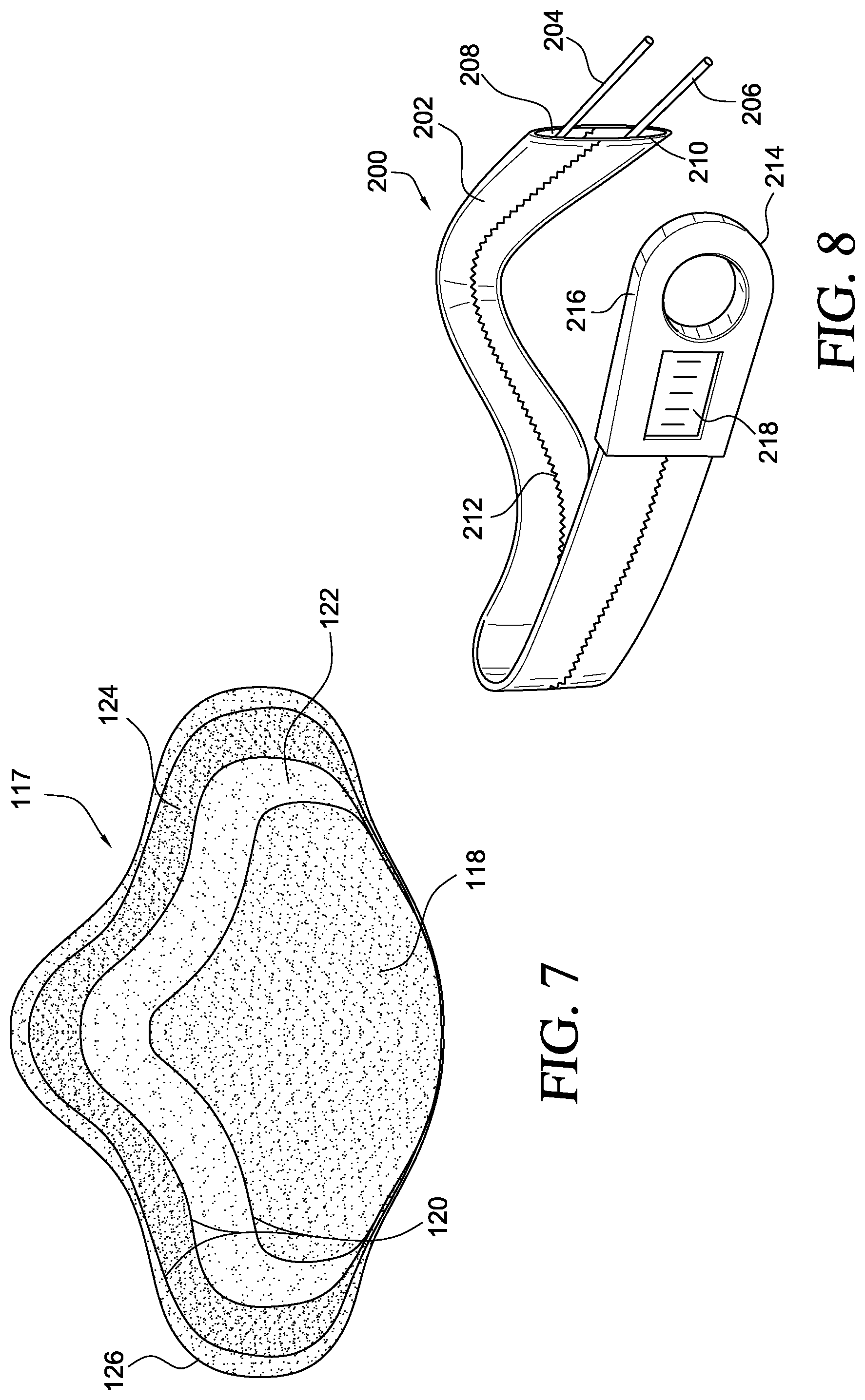
FIG. 7 is a plan view showing another variation of a plate or rigid panel in or for use with the device of FIG. 1.
FIG. 8 is a perspective schematic view of another embodiment of a strap cover of the orthopedic device.
FIG. 9 is a frontal view of another embodiment of the orthopedic device.
FIG. 10 is a rear view of the orthopedic device of FIG. 1.
FIG. 11 is a top plan view of an embodiment of the handle for use in the orthopedic device of FIG. 9.
FIG. 12 is a rear view of the handle in FIG. 11.
FIG. 13 is a side view of the handle in FIG. 11.
FIG. 14 is a front view of the handle in FIG. 11.
FIG. 15 is a rear view of the handle in FIG. 11.
DETAILED DESCRIPTION OF VARIOUS EMBODIMENTS
A. Overview
A better understanding of different embodiments of the invention may be had from the following description read in conjunction with the accompanying drawings in which like reference characters refer to like elements.
While the disclosure is susceptible to various modifications and alternative constructions, certain illustrative embodiments are shown in the drawings and are described below in detail. It should be understood, however, that there is no intention to limit the disclosure to the specific embodiments disclosed, but on the contrary, the intention is to cover all modifications, alternative constructions, combinations, and equivalents falling within the spirit and scope of the disclosure.
It will be understood that, unless a term is expressly defined in this patent to possess a described meaning, there is no intent to limit the meaning of such term, either expressly or indirectly, beyond its plain or ordinary meaning.
Any element in a claim that does not explicitly state "means for" performing a specified function, or "step for" performing a specific function, is not to be interpreted as a "means" or "step" clause as specified in 35 U.S.C. .sctn. 112, paragraph 6.
B. Various Embodiments of the Orthopedic Device and Components for Use Therewith
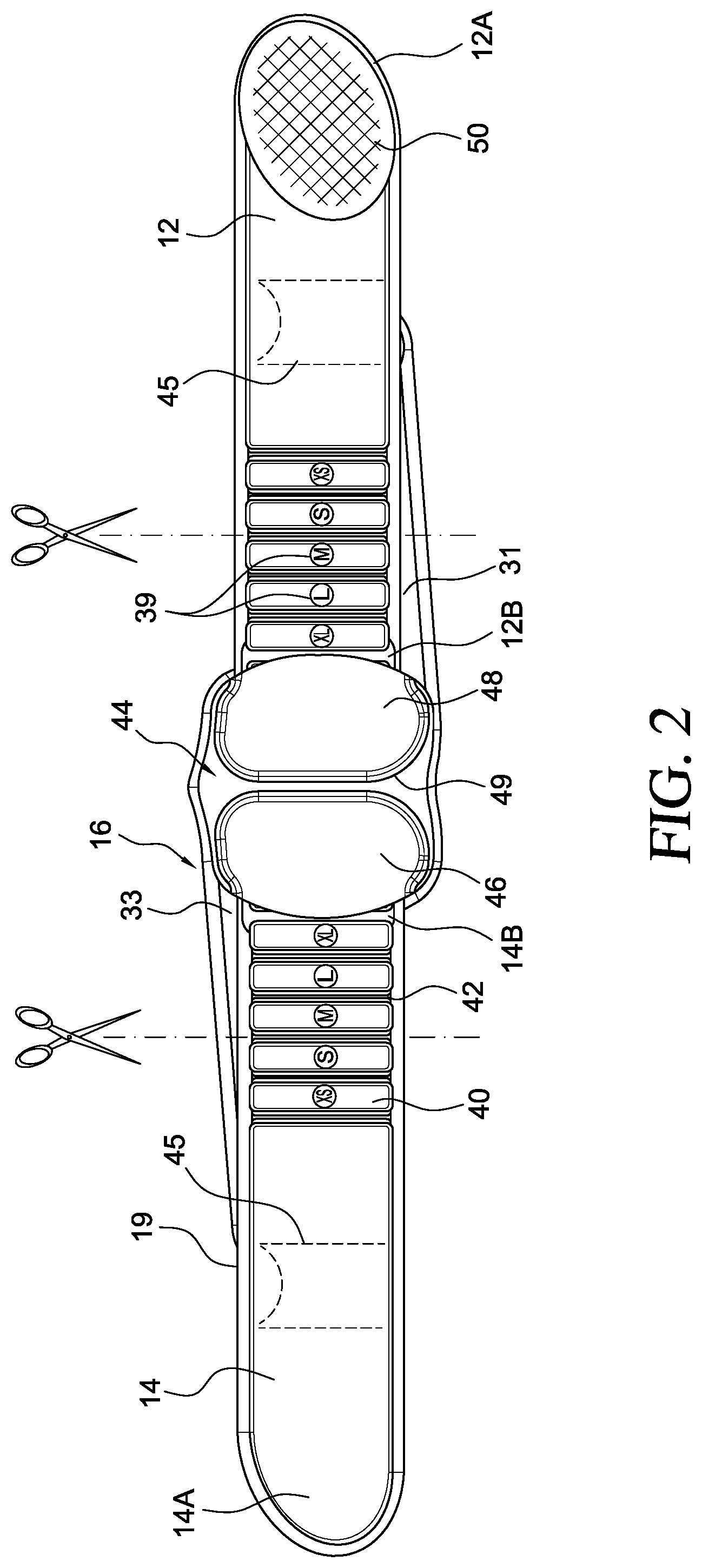
In observing a first embodiment of the orthopedic device shown in FIG. 1, the orthopedic device is in the form of a lumbo-sacral support 10 having first and second elongate belt members 12, 14 each including first and second end portions 12A, 14A; 12B, 14B. The belt members 12, 14 are securable to one another at their first end portions 12A, 14A. The belt members 12, 14 are slidably connected at their second end portions 12B, 14B to a back plate 22, and are coupled to one another via a closure system 23. The closure system 23 is arranged to move the first and second belt members 12, 14 relative to the back plate 22. A cover 16 is secured to the back plate 22 and conceals the closure system 23, and is adjustably securable to the belt members 12, 14.
Turning to FIGS. 1 and 2, the belt members 12, 14 each define an attachment portion 13, 15 located at their first end portions 12A, 14A. The front surface of the belt members 12, 14 (as shown in the orientation of FIG. 1) is generally defined as a hook-receiving or loop material. The rear surface of one of the belt members 14 (as shown in the orientation of FIG. 2), has a hook-type material section 50 which is securable over the front surface of either of the belt members 12, 14. This attachment arrangement permits easy adjustment of the belt members about the waist of the wearer.
According to the embodiment shown in FIG. 1, the attachment portions 13, 15 each define corresponding geometric shapes. For example, the illustrated attachment portions have an oval shape which, in combination with properly sizing the belt members for the dimensions of the wearer, allow for easy alignment since the wearer can mate the corresponding shapes to one another. This arrangement allows for the wearer to align the belt members at the same location over repeated uses. Then, upon proper alignment of the belt members, the wearer can just adjust the tension of the support only by pulling the arms and tensioning elements to different locations; the adjustment of the belt members remains constant and it will be easier for the clinician to merely advise just the settings of the arms instead of having to also advise on settings of the belt members relative to one another.
The belt members may be formed from a stretchable or non-stretchable material. Moreover, the belt members may have a padded core with localized areas of increased and decreased padding according to placement locations on the wearer. The belt members may have color coded sections, as in the attachment portions 13, 15, which are provided to direct the wearer as to the particular locations at which the belt members are to secure to one another.
At least in part to minimize uncomfortable pressure exerted on the wearer, the belt members define padded areas 17 surrounding the attachment portions 13, 15. These padded areas may be formed in accordance with thermoforming principles described in U.S. Pat. Nos. 5,334,135, 5,695,452 and 5,823,981, incorporated herein by reference. In addition, the belt members 12, 14 include a padded edging 19 which provides pressure relief along the edges of the belt members against the wearer. Additional padding may be provided anywhere along the device as considered necessary by the wearer or the clinician.
The belt members 12, 14 define an array of thinned sections 42 beginning at the second end portions 12B, 14B and extending toward the first end portion 12A, 14A. Between these thinned sections 42 are padded areas 40 having greater thickness than the thinned sections 42. The thinned sections 42 are preferably trimmable to reduce the length of the belt members 12, 14. A back panel 44 may be secured to a rear side of the back plate 22, and in combination with the padded areas 40, provide compressible padding to the areas surrounding the lumbo-sacral region of the wearer. Alternatively, the back panel may be replaced with a rigid panel of any of the types shown herein, and particularly by example in FIGS. 5-7.
Due to their thinned nature, sections 42 may be provided with some stretchability to the belt members, thereby allowing the belt members to better accommodate the wearer's anatomy and movement. Alternatively, the sections 42 may be formed from stretchable segments connected to the padded areas to greatly enhance any stretching of the belt members. It should be understood, however, that the belt members can be configured to either stretch or not stretch, or have localized areas of increased stretching.
Size selection indicia 39 are provided on the padded areas 40 so as to show particular size configurations. Instead of requiring a vast variety of supports having different lengths, reduced thickness or thinned sections 42 enable easy adjustment in length of the belt members by facilitating reduction of the length of the belt members by cutting along the thinned sections.
For example, the belt members may each have a first predetermined length and are reducible in length from their second end portions. The belt members have a plurality of spaced sections delimited by the thinned sections which allow for severing at these thinned sections in order to reduce the length of the belt. After the belt member has been reduced in length, the new, reduced second end portion of the belt member secures to the closure system.
The belt members may be adaptable to include various drug delivery devices, stiffeners, temperature therapy devices, and electrical stimulation treatment devices. For example, the belt members may be formed using features described in U.S. patent application Ser. No. 11/733,865 and published as U.S. patent application publication 2007/0237808, incorporated herein by reference. Also, the belt members may be configured with attachment or enclosure means or pocket 43 to accommodate other orthopedic devices, such a shell in a hip brace of the type described in U.S. patent application Ser. No. 11/438,474 and published as U.S. patent application publication 2006/0264790, incorporated herein by reference. The belt members also may define closeable pockets 45 to include any of the aforementioned treatment devices.
Turning to an embodiment of the back plate in reference to FIGS. 3, 4A and 4B, the back plate 22 slidably connects to the belt members 12, 14. According to this embodiment, the back plate is flexible or bendable to accommodate the anatomy of a wearer's back when the closure system is employed. The ability to bend about the wearer's back is particularly advantageous since the back plate can be used to support a variety of anatomical contours of a single wearer or a variety of wearers. However, while the back plate is bendable about the wearer's back, it provides sufficient rigidity to support the lumbo-sacral region of the wearer. In an alternative, the back plate may be custom formed so as to correspond to exact contours of a particular wearer wherein the back plate is substantially rigid or semi-rigid.
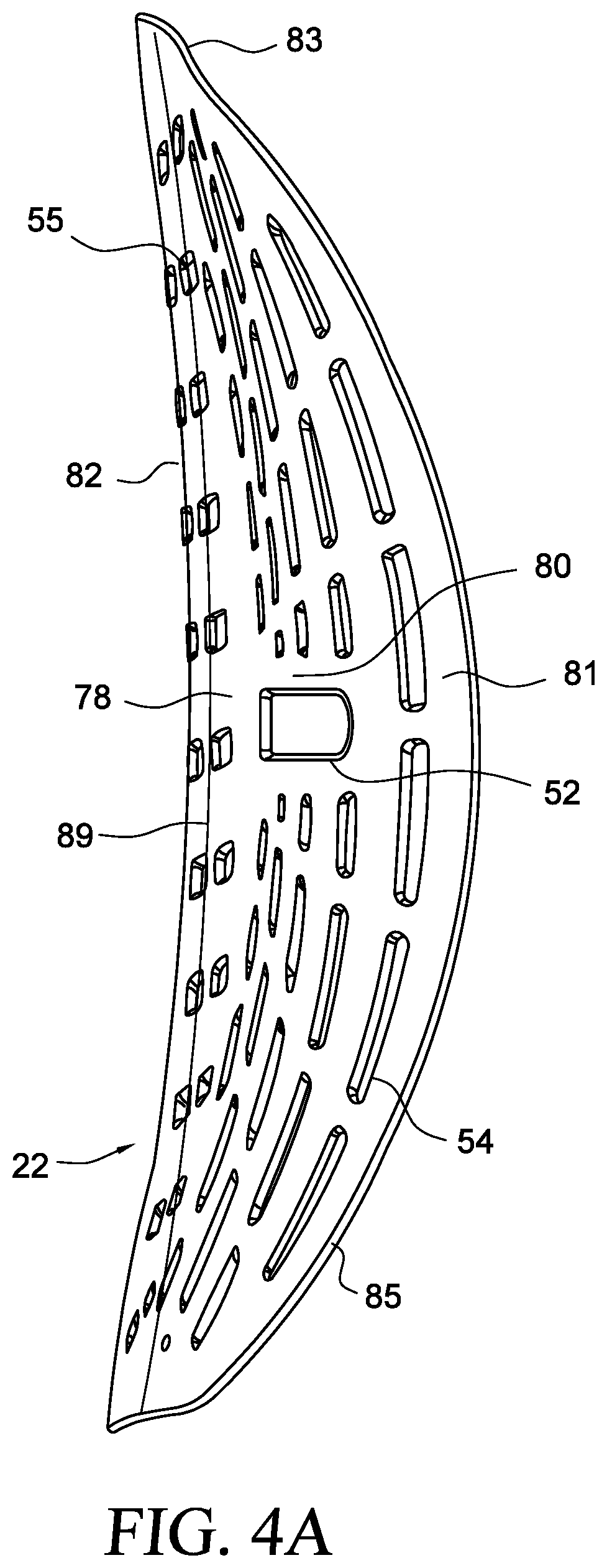
The back plate 22 has a particular anatomical geometry that is arranged to closely accommodate a wide variety of different back anatomies. For example, the plate 22 is configured to relieve pressure over a spinal region of a human back by having an outwardly directed curvature 78 on the centerline 89 generally protruding away from the spinal region. The plate 22 is arranged to apply even pressure over a paraspinal musculature of a human back by having an inwardly directed contour 80 extending over the paraspinal musculature. The plate 22 includes side wing portions 81 which are inwardly contoured toward the wearer, a tapered top portion 83 and generally rounded side portions 85, which provide coverage over side portions of the lumbar region of a wearer's back, and contribute to better pressure distribution over sensitive and less sensitive areas of a wearer's back.
The plate 22 defines a general arcuate contour 82 which provides lordosis support for the wearer. The general arcuate contour 82 is an inwardly directed contour which spans along the centerline 89 of the back plate, from the top portion of the back plate to the bottom portion of the back plate. This contour 82, in combination with pressure exerted on the plate 22 via the closure system, introduces and maintains correct lumbar lordosis for pain relief, spinal stabilization and improved posture. Because the plate is anatomically contoured with the aforementioned features, better hydrostatic lift is also created when the abdominal cavity is gently compressed and the intra-abdominal pressure is increased. Better pelvic stabilization is created by the anatomical shape of the plate since it is arranged to properly align the pelvis in relation to the spine, thereby reducing pain in the lumbo-sacral region of a wearer's back. Again, in combination with closure system, the plate allows for improved immobilization of a wearer's back by immobilizing flexion, extension, pelvic tilt, spinal rotation and lateral bending.
The back plate 22 is formed with a plurality of ventilation openings 54 allowing for a circulation of air between the back of the wearer and back plate 22. The ventilation openings 54 also permit the back plate to be sized larger than conventional back plates since it can cover a greater surface area of the wearer's back without causing undue warming of the wearer's back. Further, since the openings 54 can be arranged in a particular pattern, they can be placed in locations to facilitate greater bending of the back plate, for example at a center pattern 55 extending about the centerline of the back plate and along the outwardly directed curvature 78.
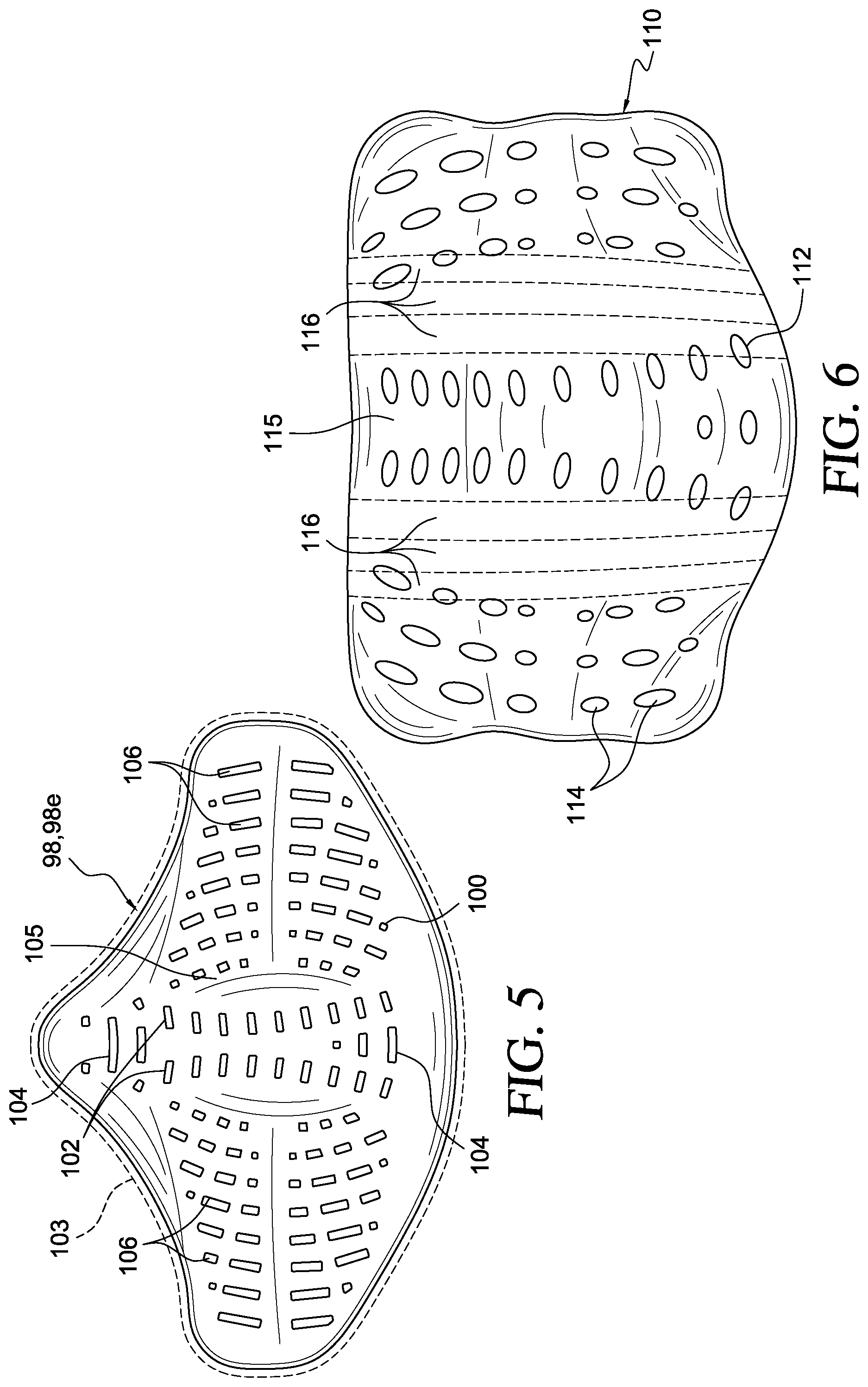
Of particular focus is the back plate variation shown in FIG. 5. Again, as with the back plate 22 of FIGS. 4A and 4B, the back plate 98 has a pattern of openings 100 which are arranged to facilitate both bending along a center line such that a pair of an array of openings 102 is located on opposed sides of the centerline. Also provided between end portions of the pair of an array of openings 102 is another array of openings 106 which further assist in the bending of the back plate 98. On opposed sides of the back plate 98 are patterns of openings which closely follow the contours of the back plate 98 when arranged in a bent configuration. The plate 98 may include an outwardly bowed portion 105 to accommodate the spinal region of a wearer, as well as a plurality of openings 104 extending generally along the spinal region so as to provide enhance breathability and flexibility. A cover 103 of a variety of types may be secured to or surround the plate 98.
Of course, it will be understood that the patterns of the openings defined by the back plate variations shown herein are not limitative, but a variety of patterns fall within the scope of the invention to facilitate bending of the back plate and assist in ventilation the support.
The plate shown in FIG. 5 may be arranged as a rigid panel 98R provided in addition to the back plate 22, and may be pivotally connected to an inner side of the plate adjacent a wearer's back, such as at locating element 242 in FIG. 9. The rigid panel may be surrounded by padding material and the padding material may be substantially ventilated using any of the padding materials described herein for use in connection with the belt members and the back plate.
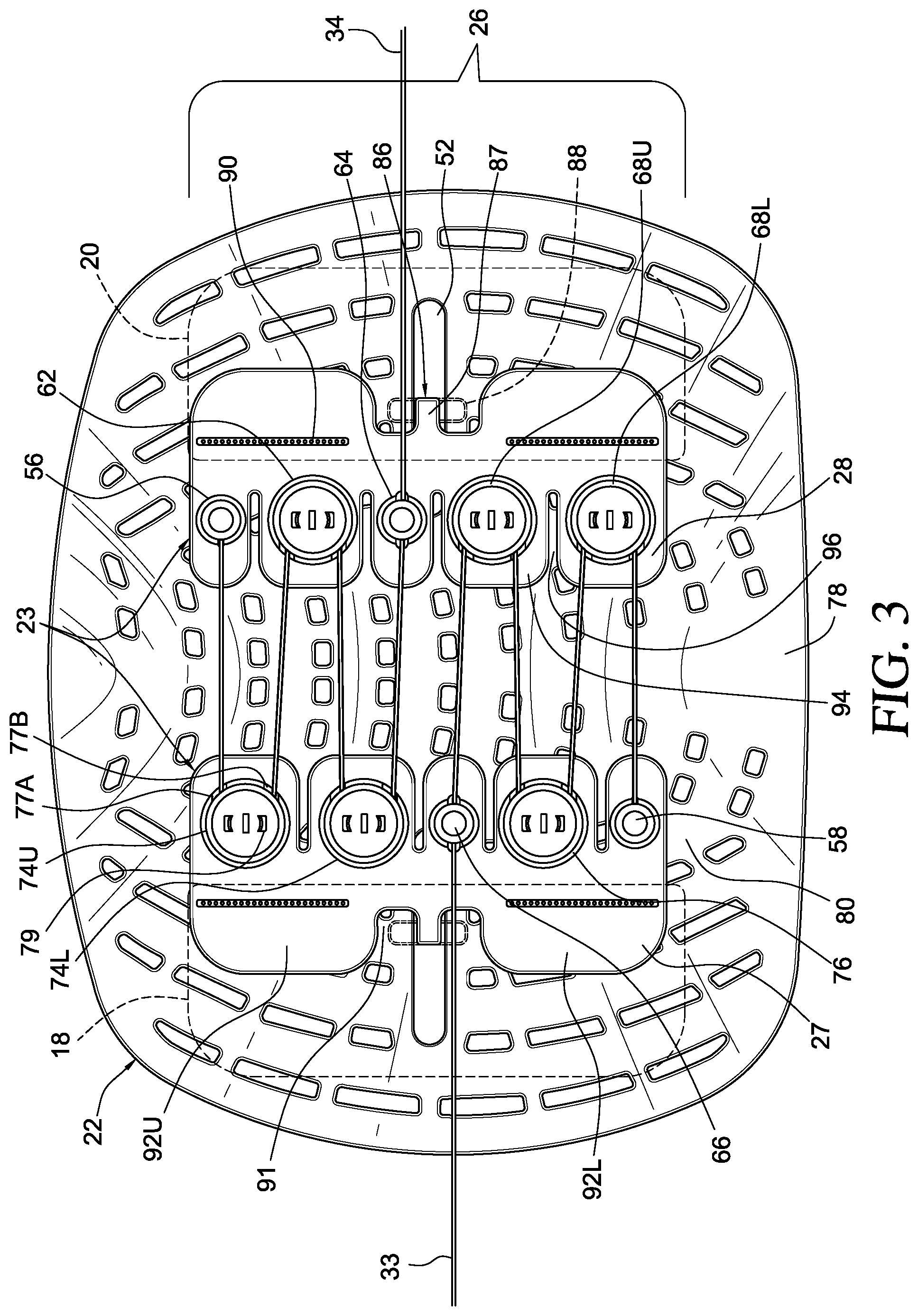
Turning to a variation of the closure system according to the embodiment of FIG. 1, FIG. 3 shows a closure system 23 including first and second pulley systems 24, 26, and first and second tensioning elements 32, 34 coupled to the pulley systems 24, 26 and arranged to tighten the device about the wearer's torso. The pulley systems 24, 26 are connected to the second end portions 12B, 14B of the belt members 12, 14 via belt attachments 18, 20. The closure system 23 is slidably mounted to the plate 22 and arranged to move the belt members 12, 14 relative to the plate 22 between first and second linear directions; outward (A) and inward (B) directions, as shown in FIG. 1.
The tensioning element may be a cable, cord, strap or other suitable element used to allow the user to apply tension and pressure over the lumbar region of the back via the closure system.
The pulley systems 24, 26 include first and second pulley connectors 27, 28 which secure to the first and second belt members 12, 14, respectively, via the belt attachments 18, 20, and secure on opposed sides of the plate 22 in the inwardly directed contour 80 extending over the paraspinal musculature of a wearer's back. The first tensioning element 32 which extends outwardly from the first pulley system 24 at a lower portion whereas the second tensioning element 34 extends outwardly from the second pulley system 26 at an upper portion.
The pulley connector 27 includes a top set of pulleys comprising a top upper pulley 74U and a top lower pulley 74L through which the second tensioning element 34 extends. A first end of the second tensioning element 34 is fixably secured to the anchor post 56 carried by the pulley connector 28. The second tensioning element 34 runs between the top upper pulley 74U on the pulley connector 27 by extending through inlet 77A and outlet 77B and wrapping around a spindle or bearing 79 mounted in each individual pulley. The second tensioning element 34 extends through the top pulley 62 on the pulley connector 28, returning to the top lower pulley 74L, and then being directed through outlet post 64.
The tensioning element 32 is arranged to extend between the pulley connectors 27, 28, while having a first end fixably secured to anchor post 58 carried by the pulley connector 27. The tensioning element 32 also extends between bottom pulleys 68U, 68L located on the pulley connector 28, and the pulley 76 so as to eventually extend through outlet post 66 on the pulley connector 27.
It is preferred, while not limiting, that there are fewer pulleys amounting to an 8:1 pulley system (combined with both pulley connectors, and 4:1 for each tensioning element). It has been found that when there is less travel of the tensioning element through the pulley system, easier adjustment of the pressure on the lumbar region of the wearer is obtained. When combined with the bearings inside the pulleys, there is an elimination of friction which greatly improves the ability for wearers of the device to make adjustments of the tensioning elements. This arrangement leads to improved immobilization of the lumbar region, while providing improved pelvic stabilization, hydrostatic lift and lordosis support.
A sliding arrangement 86 is used to mount the pulley connectors 27, 28 of the pulley systems 24, 26 onto the panel 22. Each pulley connector 27, 28 defines a neck 87 extending outwardly and downward from an outer side (contrasted with an inner side oriented towards the centerline of the back plate). An elongate arm 88 extends in a cross-wise manner from the neck 87.
The neck 87 is arranged to slidably engage a slot 52 formed by the back plate 22, and located in the inwardly directed contour 80 extending over the paraspinal musculature and outside of the outwardly directed curvature 78. The arm 88 retains the neck 87 within the slot 52 and generally slides against a rear surface of the back plate 22 as the second pulley connector 26 is moved relative to the back plate between the directions A, B shown in FIG. 1. The downward bend of the neck 87 may be configured in a manner that permits the second pulley connector to adjustably rotate relative to the back plate in order to permit additional adjustment of the back plate relative to the second belt member.
The pulley connectors 27, 28 each define upper and lower tabs 92U, 92L along the outer side, and a recess 91 in which the sliding arrangement 86 is located. The pulley connectors 27, 28 also define a back mount 74 which are used to retain the belt attachments 18, 20 to the pulley connectors. Because the pulley connectors may be arranged in a resilient or semi-rigid configuration (while permitting some bending to accommodate tightening of the support about the torso of the wearer), a line of apertures 90 are likewise formed by the pulley connectors so as to permit the corresponding belt attachment to be stitched to the pulley connector.
The pulley connectors define a plurality of fingers 94 along the inner side. Each of the fingers 94 carries one of the pulleys, and each finger is spaced by a notch 96. The arrangement of the fingers 94 and the notches 96 permit flexure of the fingers relative to the remainder of the pulley connector, thereby better accommodating the support due to tightening of the tensioning elements.
It is preferable to include opposed tensioning elements of the type shown in the embodiment of FIG. 1 in order to eliminate rotation of the support on the wearer. In effect, the tensioning elements counteract rotation from one another, thereby more securely adjusting to the wearer when the tensioning elements are tensioned.
Accordingly to the embodiment of FIG. 1, the belt attachments 18, 20 are each defined as a pair of flaps having opposed surfaces of hook material. The hook material engages the hook-receiving material of the belt members and effectively couples the closure system to the belt members.
FIG. 4C shows how the advantageous arrangement of the embodiment of the device 230 having a closure system in combination with the plate 22 and associated belt members 12, 14 applies an even distribution of pressure 95 over the paraspinal musculature of a wearer's back. In this instance, a rigid panel 98R is provided in combination with the plate 22, but even without the rigid panel 98R, the even distribution of pressure 95 over the paraspinal musculature may be obtained. As for the spinal region, there is minimal pressure leading to relief 93 exerted on the wearer's back.
The result of the combination of these features of the device in FIG. 4C leads to a pressure mapping in FIG. 4D which shows the relief 93 along the spinal region and gentle even contact over the paraspinal musculature in the remaining areas of the lumbar region. It follows that there are no pressure spikes (or at least minimal) which may lead to discomfort when a wearer uses the device.
Referring back to the strap cover, FIG. 1 illustrates that the cover 16 extends over the back plate 22. According to this embodiment, the cover 16 is secured around the back plate 22 with stitching 30 along portions between the belt members 12, 14. The cover 16 defines first and second arms 31, 33 which generally correspond to the first and second belt members 12, 14, respectively. At least the first and second arms 31, 33 are elasticized and are readily positionable relative to the first and second belt members 12, 14.
The first and second arms 31, 33 define first and second channels 35, 37, respectively, through which the first and second tensioning elements 32, 34 extend, respectively. The channels 35, 37 may be formed in a variety of constructions, but it is preferable that they conceal the tensioning elements so as to prevent the tensioning elements from catching on any object that the wearer may contact or any clothing. For example, in embodiment of FIG. 1, the channels are sewn into two layers of material used to form the arms 31, 33. Alternatively, channels may be formed along the surface of the cover by adding a strip layer of material.
Each of the arms 31, 33 includes a handle 36, 38 which is secured to an end portion thereof. A second end of each tensioning element is secured to the handle 36, 38. The handle 36, 38 may be formed in a variety of different configurations, for example as having a raised handle portion of the type shown in FIG. 1 which permits the wearer to insert fingers into the handle portion to better grasp the handle and thereby easily tighten the arms (and tensioning elements) relative to the belt members. Of course, other grasping configurations are possible which allow for the wearer to easily grasp the end portions of the arms, as will be shown in FIGS. 11-15.
Each end portion of the arms includes an attachment portion which allows for securing the arm end portions relative to the belt member. For example, the outer surface of the belt members may be formed from a hook-receiving material and an inner side of the arms at a location generally corresponding to the handle may include a hook patch. Therefore, upon drawing the arms away from the back panel and by the tensioning elements, the wearer can secure the handles at a variety of locations on the belt members to tighten the support about the torso of the wearer.
In a variation of the cover, the handles may be removable from the arms and the tensioning elements so that the arms can be folded over to reduce their length for certain wearer's of the support having a narrower torso. Once the arms are properly sized, the handle may be attached to the arm having a reduced length and the tensioning element can accordingly be reattached.
In observing FIG. 2, the back panel 44 has cushioning features that are arranged to be adjacently placed against the wearer to provide comfort to the wearer. In particular, as the arms are tightened relative to the belt members, the pressure exerted against the wearer is minimized by the back panel. The back panel comprises first and second padded regions 46, 48 which are spaced by a thinned transition area 49. The transition area 49 permits better bending of the back panel 44 as the back plate 22 is similarly bent to accommodate the wearer.
The back panel 44 is shaped in an ergonomic form much like the aforementioned form of the back plate 22. Further, the back panel 44 may be formed from a ventilated three-dimensional fabric or a thermoformed padding material or combination thereof, as discussed above in connection with the belt members, so as to work in combination with the ventilation openings of the back plate to better provide a circulation of air through the support to allow for added comfort to the wearer.
FIG. 6 illustrates an embodiment of a front plate 110 which may be used in combination with the support 10. The front plate 110 removably secures to the inner surface of the belt members. The front plate 110 defines a pattern of openings 112, in a similar manner to the openings 102 of the back plate 98, which assist in bending the front plate about the torso when tightened against the user. The front plate 110 also defines a plurality of ventilation openings 114 which further assist in permitting a circulation of air to make the support more comfortable to the wearer. A plurality of openings 115 are particularly provided along the spinal region to provide ventilation and flexibility.
The front plate may be wrapped with a fabric material, such as a three-dimensional fabric of any type described by U.S. patent application Ser. No. 11/723,604 and published as U.S. patent application publication 2007/0185425, incorporated herein by reference. The fabric may be combined with a padding material, such as foam, and is preferably breathable so as to work in combination with the ventilation openings.
As depicted by the sections 116 in FIG. 6, the front and back plates may define a surface curvature (resulting in the plates having a curved cross-section) which follows the contours of general human anatomy. In other words, the front and back plates are not flat plates, but have a specific geometry which applies more even pressure onto the wearer than in conventional flat plates. For example, surface curvatures in the back plate can lift the plate away from the spinal column of the wearer and apply even pressure on either side of the spinal column so as to form a shape which imparts a very rigid plate when placed proximate to the wearer with a thin sheet of plastic forming the plate. It will be understood, however, that the support is not limited to including curved front and back plates; conventional flat plates may be employed.
As illustrated in FIG. 7, a variation of the back plate or rigid panel 117 is shown having a variety of different size configurations 118, 122, 124, 126. These size configurations each have a trim line 120 which is formed by a reduced thickness enabling the clinician to trim the back plate to a suitable size corresponding to the wearer. The back panel and the front plate may also have such trim lines so that the entirety of the support along with the belt members may be modified to the appropriate size of the wearer.
In referring to FIG. 8, an embodiment of the arms belonging to the cover is shown as having a dosage meter. In this variation, the arms comprise a strap 200 having a strap body 202 divided by a stitched divider 212. The divider 212 forms upper and lower channels 208, 210 through which upper and lower tensioning elements 204, 206 connecting to a closure system are inserted. The tensioning elements 204, 206 secure to a handle 214 having a grasping feature 216 in the form of an opening.
The tensioning elements 204, 206 are connected to a tension meter 218 which provides indicia showing relative degrees of tightening of the tensioning elements about the torso of the wearer. The tension meter may include a spring which elongates at prescribed tension settings which can correspond to indicia. The purpose of the tension meter is to provide a calibrated load that is measured by the clinician so that instructions can be given to the wearer at which tension setting the wearer should adjust the tensioning elements.
In a variation, the tension meter may include printing on an elastic segment which is revealed once the tensioning elements and the elastic are stretched to a certain point.
In observing FIGS. 9 and 10, another embodiment of the orthopedic device is shown bearing some features different from the embodiment of FIG. 1. According to this embodiment, the device 230 includes first and second belt members 232, 234 which are secured to a back plate 236 via belt attachments 260, 262. The back plate 236 is shown as having a covering 237. The back plate 236 is contoured down the middle or spinal region 240 to correspond to the anatomy of the lower back or lumbar region of the back, as well as regions 254, 258 outside the middle region 240 in a manner described above in connection with other embodiments of the back plate. A breathable covering 264 surrounds portions of the periphery of the back plate 236.
The first belt member 232 includes a fastening element 238 located on the inner surface, such as hook material, which secures to the outer surface of the second belt member 234.
An inner surface of the covering 237 includes a locating element 242 which allows for the user to align and mate to a corresponding supplementary support element thereto. For example, a bladder system 257, which is either inflatable or pre-inflated, may be secured to the covering 237. By providing the locating element, the wearer can be assured that the supplementary support element is positioned in the proper location. Alternatively, a rigid panel 259, such as the rigid panel 98R may be secured at the locating element 242 so as to provide additional support to the plate.
The locating element 242 may be a colored patch having a contrast relative to the color of the covering which is adapted to engage hook elements located on a supplementary support element. The end portion of the second belt member 204 may likewise include another locating element 244 which is located on the front of the user or abdominal region, and arranged to receive another supplementary support element, such as an anatomically contoured front plate 256.
As shown in FIG. 10, the device 230 includes a closure system which uses tensioning elements 246, 250 having handles 248, 252 located at the end thereof. The tensioning elements 246, 250 are exposed and the handles 248, 252 are adapted to engage a hook receivable outer covering 266 of the belt members 232, 234. A hook element 268 is provided on the belt member 232 to secure to the outer covering.
Turning to FIGS. 11-15, an example of a handle 300 useable in the device 230 shown in FIGS. 9 and 10 is depicted.
FIG. 11 illustrates the handle 300 as including a first part 302 which definitively defines a periphery of the handle 300. A second part 304 is integrally secured to the first part 302, and is at least exposed on the inner surface of the handle 300, as shown in FIG. 12. The second part 304 extends from the mid-span 320 to the front portion 314 of the handle 300. The first part 302 is substantially flexible, and the second part 304 is more rigid than the first portion 302.
In accordance with one variation, the first part 302 is constructed from a polymeric material having flexibility and resiliency. The second part 304 is also constructed from a polymeric material which is substantially rigid. The first and second parts are integrally secured to one another forming a single component. A leading section 312 of the second part 304 is exposed on the outer surface at the front portion 314, as depicted by FIG. 11, whereas the entirety of the periphery of the second part 304 is exposed on the inner surface of the handle, as depicted by FIG. 12. As shown in FIGS. 13-15, the second part 304 is retained within the first part 302, and is flush with the periphery of the first part 302.
The handle 300 defines an opening 306 located near a mid-span 320 and rear portion 308 of the handle 300. The rear portion 308 of the handle, as delimited by one end of the mid-span at 320, is substantially flexible due to the lack of the second portion 304. On an undersurface of the handle, as depicted in FIG. 12, a patch of hook material 310 extends from the front portion 314 to an end of the mid-span delimited by line 320, and the hook material 310 tracks at least the periphery of the second part 304. This allows for the user to easily flex and remove the handle 300 from the outer surface of the belt members. In other words, in an inner surface of the handle may include a hook material located at the second handle portion and only at a location on the first handle portion adjacent the second end portion
In yet another variation, anchors having a shape generally conforming to at least part of the handles may be secured to the belt members so that the handle is secured at the anchors. The anchors can have a retention wall which includes a lip preventing further movement of the handle relative to the back plate so as to define a maximum tension that the wearer should set the arms. The clinician can set the anchors at various locations on the belt members as the treatment of the wearer changes, and more or less tension is required.
The handle 300 includes a recess 316 for securing to the cord belonging to the closure system. An opening 318 at the middle of the thickness of the handle is defined which is in communication with the recess 316. The opening 318 is located at the front portion 314 through which the cord extends to the closure system thereby assuring that the cord is pulled generally along the axis of the handle.
As illustrated in FIG. 13, because the second part 304 is substantially rigid, the handle 300 is contoured with bend 316 so as to be anatomically compliant to the torso of the wearer.
Suitable fasteners 324, such as rivets, may be used to secure the hook material onto the handle 300. In variations, other types of fasteners may be used in place of hook and loop material to secure the tensioning elements to the handles. Examples include buckles, snaps and other suitable types of corresponding fasteners on the belt members and the handles.
While the foregoing embodiments have been described and shown, it is understood that alternatives and modifications of these embodiments, such as those suggested by others, may be made to fall within the scope of the invention. Moreover, any of the principles described herein may be extended to any other orthopedic devices.
* * * * *
References
D00000
D00001
D00002
D00003
D00004
D00005
D00006
D00007
D00008
D00009
D00010
XML
uspto.report is an independent third-party trademark research tool that is not affiliated, endorsed, or sponsored by the United States Patent and Trademark Office (USPTO) or any other governmental organization. The information provided by uspto.report is based on publicly available data at the time of writing and is intended for informational purposes only.
While we strive to provide accurate and up-to-date information, we do not guarantee the accuracy, completeness, reliability, or suitability of the information displayed on this site. The use of this site is at your own risk. Any reliance you place on such information is therefore strictly at your own risk.
All official trademark data, including owner information, should be verified by visiting the official USPTO website at www.uspto.gov. This site is not intended to replace professional legal advice and should not be used as a substitute for consulting with a legal professional who is knowledgeable about trademark law.