Pump assembly
Dietzsch , et al. November 3, 2
U.S. patent number 10,823,167 [Application Number 16/263,203] was granted by the patent office on 2020-11-03 for pump assembly. This patent grant is currently assigned to WILDEN PUMP AND ENGINEERING LLC. The grantee listed for this patent is WILDEN PUMP AND ENGINEERING LLC. Invention is credited to Maclovio Antonio Aguilar Sepulveda, Curtis W. Dietzsch, Nathan Hale, William K. Watson, Sr..


| United States Patent | 10,823,167 |
| Dietzsch , et al. | November 3, 2020 |
Pump assembly
Abstract
A pump assembly includes a pump and a base. The pump has mounts located at multiple positions on the pump to effect different configurations of the assembly. Each mount includes two engagements spaced apart on the pump. The base has a retainer constructed to slidably engage one engagement and a seat constructed to support the other engagement. The seat has a socket with two holes extending into the base. A bracket includes a jaw engageable with the second engagement and two locking pins extending from the bracket for sliding engagement with the socket. The locking pins retain the bracket and jaw from moving away from the base. A fastener engages the bracket with the base so the two locking pins cannot slidably disengage the socket.
| Inventors: | Dietzsch; Curtis W. (Riverside, CA), Watson, Sr.; William K. (Upland, CA), Hale; Nathan (Hesperia, CA), Aguilar Sepulveda; Maclovio Antonio (Riverside, CA) | ||||||||||
|---|---|---|---|---|---|---|---|---|---|---|---|
| Applicant: |
|
||||||||||
| Assignee: | WILDEN PUMP AND ENGINEERING LLC
(Grand Terrace, CA) |
||||||||||
| Family ID: | 1000005156463 | ||||||||||
| Appl. No.: | 16/263,203 | ||||||||||
| Filed: | January 31, 2019 |
Prior Publication Data
| Document Identifier | Publication Date | |
|---|---|---|
| US 20200248683 A1 | Aug 6, 2020 | |
| Current U.S. Class: | 1/1 |
| Current CPC Class: | F04B 43/06 (20130101); F04B 39/121 (20130101); F04B 53/16 (20130101); F04B 45/043 (20130101); F04B 45/053 (20130101); F04B 53/22 (20130101); F04B 43/025 (20130101); F04B 39/14 (20130101); F04B 43/026 (20130101); F04B 45/04 (20130101) |
| Current International Class: | F04B 53/22 (20060101); F04B 43/02 (20060101); F04B 45/04 (20060101); F04B 39/12 (20060101); F04B 45/053 (20060101); F04B 53/16 (20060101); F04B 39/14 (20060101); F04B 43/06 (20060101) |
References Cited [Referenced By]
U.S. Patent Documents
| 3022740 | February 1962 | Wilfley |
| 3169486 | February 1965 | Freed |
| 4877984 | October 1989 | Colwell et al. |
| 4900224 | February 1990 | Timperi |
| 5184941 | February 1993 | King |
| 5221192 | June 1993 | Heflin |
| 5354182 | October 1994 | Niemiec |
| D382277 | August 1997 | Feitel |
| 5760513 | June 1998 | Morishita et al. |
| 5860794 | January 1999 | Hand |
| 6336794 | January 2002 | Kim |
| D512441 | December 2005 | Iwata |
| 7614855 | November 2009 | Cook |
| 8066028 | November 2011 | Kees |
| 8109741 | February 2012 | Huang |
| 8360745 | January 2013 | Dietzsch |
| 9862267 | February 2018 | Gerhardt et al. |
| D817360 | May 2018 | Dietzsch |
| 2003/0030021 | February 2003 | Hawkins |
| 2005/0095152 | May 2005 | Dale |
| 2011/0186709 | August 2011 | Stupnik |
| 2016/0201663 | July 2016 | Treml |
| 2019/0170132 | June 2019 | Zhang |
Other References
|
International Search Report & Written Opinion re PCT/US20/15479, dated Apr. 20, 2020. cited by applicant. |
Primary Examiner: Bobish; Christopher S
Attorney, Agent or Firm: Karish & Bjorgum, PC
Claims
What is claimed is:
1. A pump assembly comprising an air driven diaphragm pump with a housing, an intake port and an outlet port, the ports being adjacent one another on a periphery of the housing, the pump including at least two mounts, each mount including a pair of engagements spaced apart on the pump, the mounts being angularly displaced from one another; a base including a retainer constructed to slidably engage a first engagement of the pair of engagements and a seat constructed to support a second engagement of the pair of engagements with the retainer slidably engaged with the first engagement of the pair of engagements, the seat having a socket; a bracket including a jaw engageable with the second one of the pair of engagements and a locking pin having a surface facing the jaw and engageable with the socket; a fastener engaged with the bracket and the base with the locking pin engaged with the socket; the base having a central hole therethrough receiving the ports with the pump mounted to the base at a first of the at least two mounts, and having spaced cradle elements supporting the pump with the pump mounted to the base at a second of the at least two mounts with the ports angularly displaced from the central hole.
2. A pump assembly comprising a pump including at least one mount, each mount including two engagements spaced apart on the pump; a base including a retainer constructed to slidably engage a respective first engagement of the pair of engagements and a seat constructed to support a respective second engagement of the pair of engagements with the retainer slidably engaged with the first engagement of the pair of engagements, the seat having a post and a socket having two holes extending into the base, each of the two holes having an undercut section in the base; a bracket including a channel, a jaw engageable with the second engagement of the pair of engagements and two locking pins extending from the bracket, each of the two locking pins having a lug with a surface facing the jaw and engageable in one of the holes with one of the undercut sections, respectively, the channel receiving the post with the socket holes receiving the locking pins, the bracket sliding on the seat with the channel positioned about the post, the second of the two engagements being fixed between the seat and the jaw with the lugs engaged with the undercut sections; a fastener engaging the bracket and the post of the seat with the lugs engaged with the undercut sections.
3. The pump assembly of claim 2, the fastener restraining the locking pins from lateral disengaging from the socket.
4. The pump assembly of claim 2, the retainer and the jaw constructed to engage each of the respective engagements.
5. The pump assembly of claim 2, the pump including two mounts, the mounts being perpendicular to one another.
6. The pump assembly of claim 5, the pump being an air driven diaphragm pump with a housing, an intake port and an outlet port, the ports being adjacent one another on a periphery of the housing, the base having a central hole therethrough receiving the ports with the pump mounted to the base at a first of the two mounts and having spaced cradle elements supporting the pump with the pump mounted to the base at a second of the two mounts with the ports angularly displaced from the central hole.
Description
BACKGROUND OF THE INVENTION
The field of the present invention is pumps.
Many pumps have the capability of operating in multiple orientations. An advantage of this capability is that the pump may be oriented to most conveniently interface with plumbing and other devices associated with the pump. The pump also may be oriented to most conveniently be stably supported or fixedly mounted to existing structure.
Many applications for certain types of pumps such as air driven diaphragm pumps are advantaged by secure attachment because of unbalanced accelerations during operation. At the same time, such pumps have versatile capabilities and operate in multiple orientations, making them useful as tools taken from application to application. A secure and versatile mounting can be advantageous.
SUMMARY OF THE INVENTION
The present invention is directed to the assembly of a pump with a base. To accomplish the assembly, a mount includes a retainer and a seat on the base to mount the pump having two mutually-displaced engagements. A bracket cooperates with the seat to capture one of the engagements. The bracket includes a jaw and a locking device with a surface facing the jaw. The locking device engages with a socket in the base. The jaw and the seat thus retain the pump. A fastener engages both the bracket and the base to retain the bracket locked with the engagement of the mount. With multiple mounts, the base can be mountable in various orientations to the pump engagements.
In the preferred embodiment, an air driven diaphragm pump has a generally cylindrical shape with inlet and outlet manifolds adjacent to one another extending from the periphery. The pump has a plurality of angularly spaced mounts, each with two engagements. Each engagement is defined by opposite facing, uniformly spaced surfaces on the pump. There are three mounts angularly spaced at 90.degree. from the most adjacent mount, allowing three pump orientations. The engagements of each mount being opposite facing, uniformly spaced surfaces, the pump may be engaged with the base in either direction with any of the three mounts.
The base is a functional plate. A hole therethrough accommodates the ports in one pump orientation. The base retainer is conveniently a passive hook spaced from the base to receive the spaced surfaces of an engagement on the pump. A seat also passively receives the associated engagement. The bracket includes a jaw that is spaced from the seat to meet the spaced surfaces of the associated engagement of the mount when the bracket is positioned on the seat. There are two locking pins on the bracket that engage the socket in the seat with the bracket positioned on the base. These locking pins include lugs facing the jaw which engage undercut sections in the socket by sliding the bracket on the base. The lugs engaging the socket retain the bracket in engagement with the pump. The fastener, cooperating with an aligning post and channel, is used to keep the lugs engaged with the socket.
Accordingly, it is a principal object of the present invention to provide a versatile pump and mounting assembly. Other and further objects and advantages will appeal hereinafter.
BRIEF DESCRIPTION OF THE DRAWINGS
FIG. 1 is an isometric view of a pump assembly illustrating the retainer of the base with the pump in a first orientation;
FIG. 2 is an isometric view of the pump assembly illustrating the seat and bracket of the base with the pump in the first orientation;
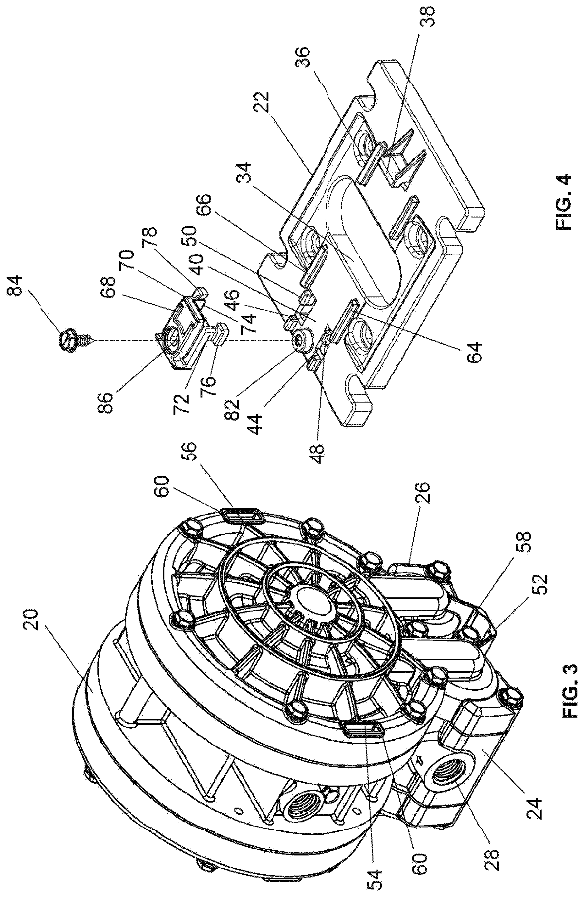
FIG. 3 is an isometric view of the pump without a base assembled therewith;
FIG. 4 is an isometric exploded assembly view of the base, bracket and fastener of the assembly;
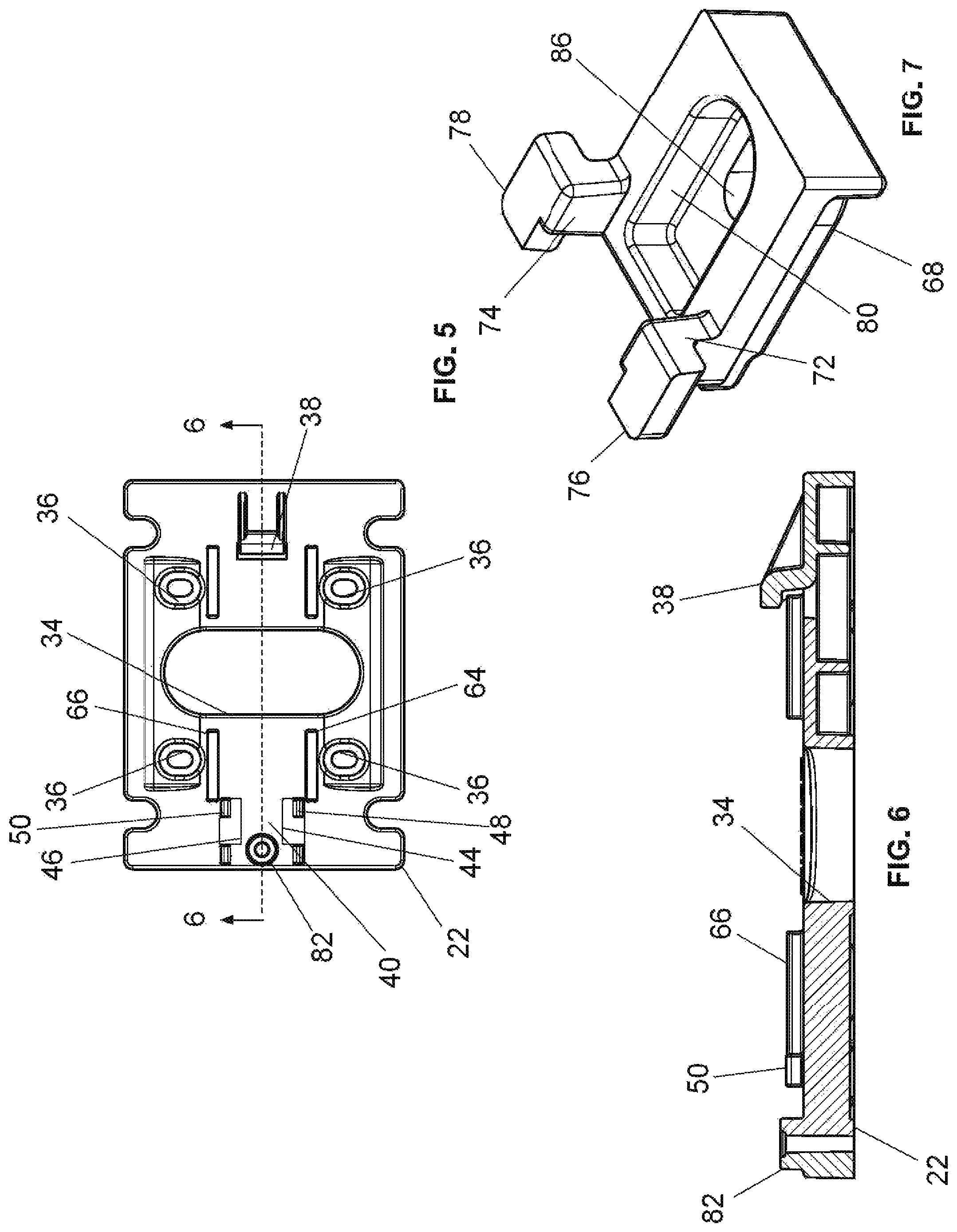
FIG. 5 is an orthographic plan view of the base of the pump assembly;
FIG. 6 is a cross-sectional view of the base taken along line 6-6 of FIG. 5;
FIG. 7 is an isometric bottom view of the bracket of the pump assembly from the back end of the bracket;
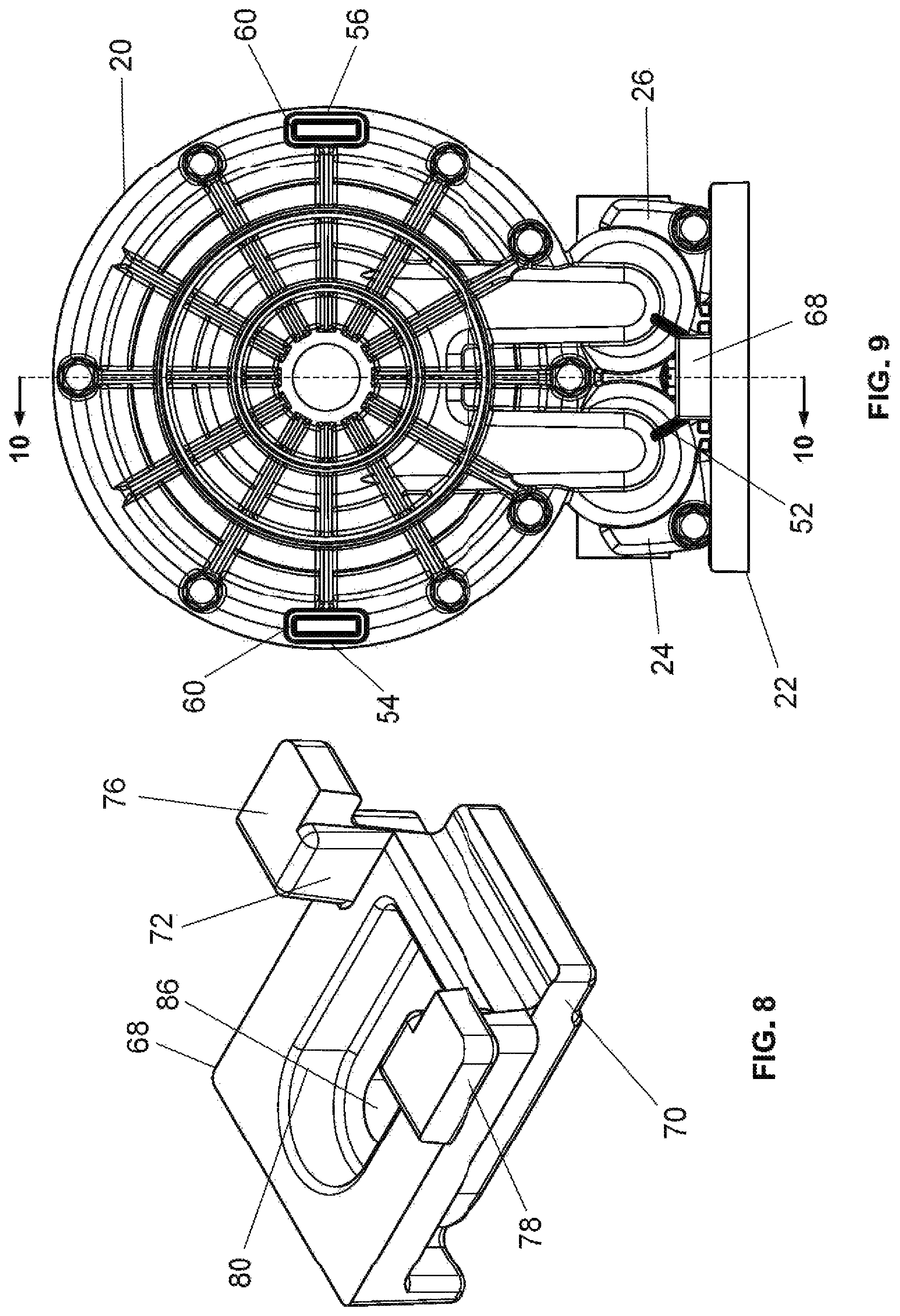
FIG. 8 is an isometric bottom view of the bracket of the pump assembly from the jaw end of the bracket;
FIG. 9 is a front view of the pump assembly illustrating the bracket of the mount with the base in the first orientation;
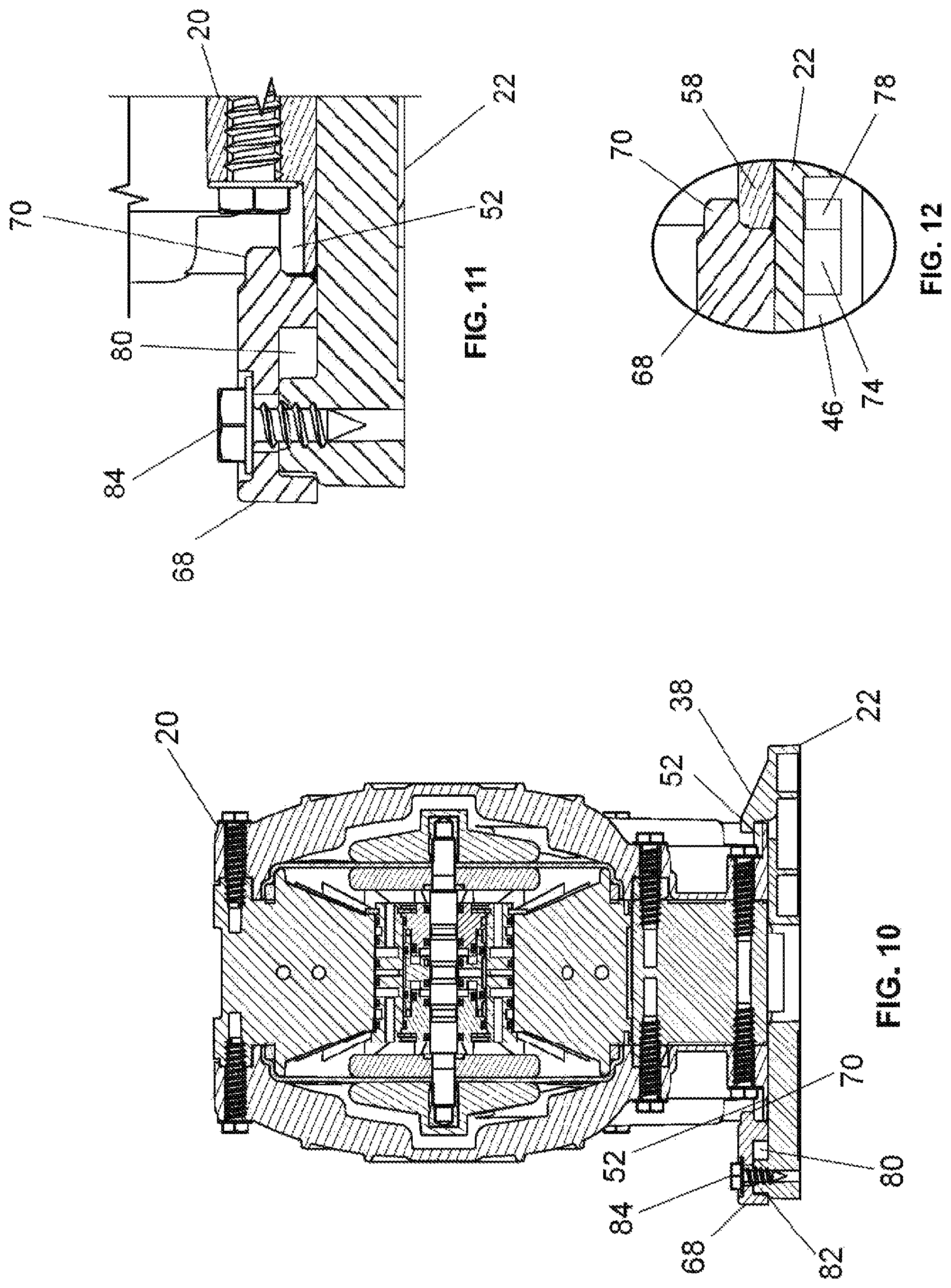
FIG. 10 is a cross-sectional view of the pump assembly taken along line 10-10 of FIG. 9;
FIG. 11 is a detail view of the bracket assembly as shown in cross section in FIG. 10;
FIG. 12 is a detail view of the bracket assembly taken in cross section through a hole in the slot of the base.
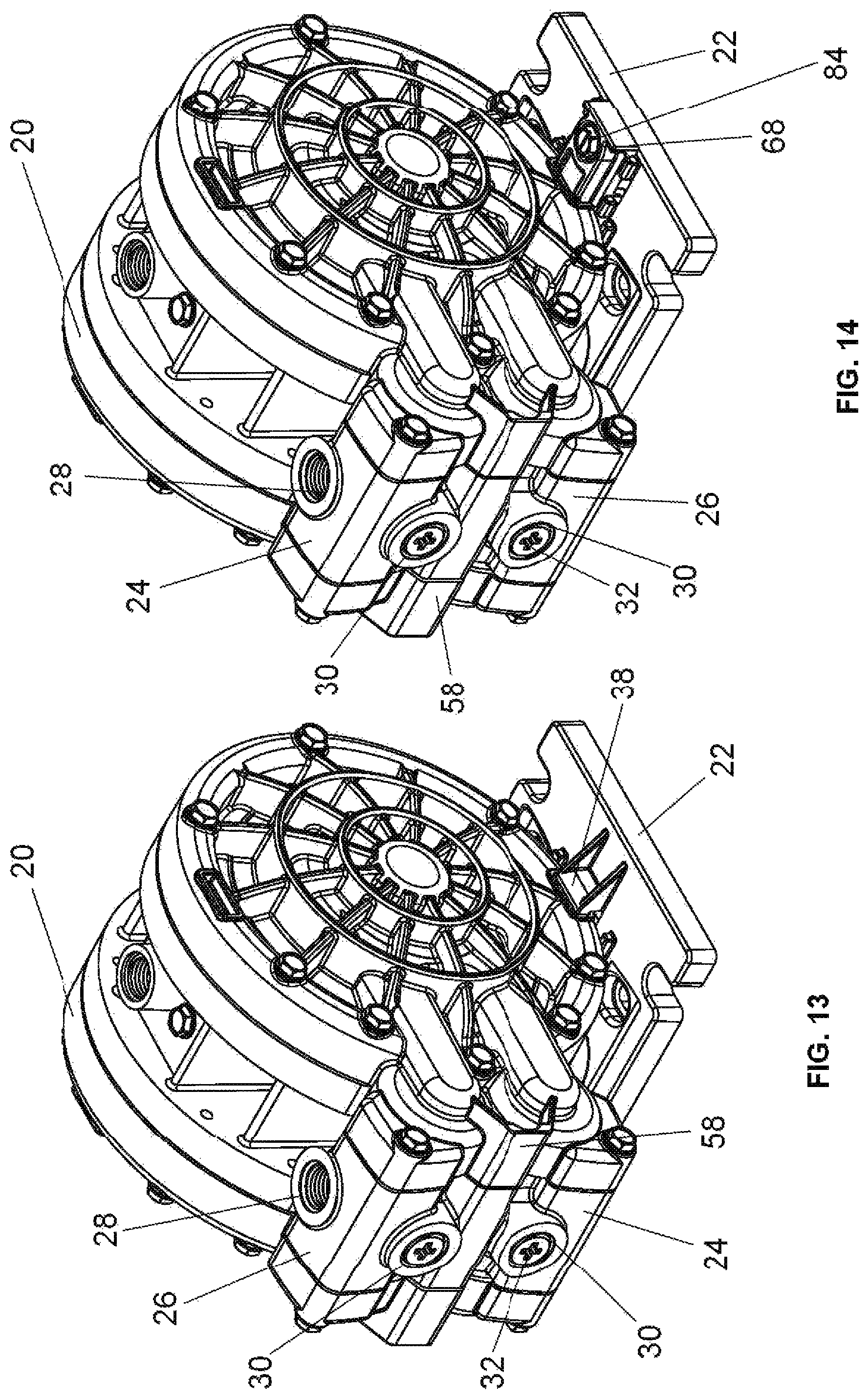
FIG. 13 is an isometric view of the pump assembly illustrating the retainer of the base with the pump in a second orientation;
FIG. 14 is an isometric view of the pump assembly illustrating the seat and bracket of the base with the pump in the second orientation.
DETAILED DESCRIPTION OF THE PREFERRED EMBODIMENTS
Turning in detail to the drawings, a pump 20 is illustrated with a base 22 in a single preferred embodiment in all of FIGS. 1 through 14. The pump illustrated is an air driven double diaphragm pump generally cylindrical in configuration with inlet and outlet manifolds 24, 26 adjacent one another and extending from the periphery of the generally cylindrical pump body. The manifolds 24, 26 each include two ports 28, 30 at 90.degree. to one another for added versatility of attachment for pumped fluid. As visible in FIGS. 13 and 14, one of the two ports 28, 30 on each may be blocked by a threaded plug 32 to provide a single inlet and single outlet for the pumped fluid to and from the pump 20.
The base 22 is a functional plate having a central hole 34 therethrough. The base 22 further includes four mounting holes 36 for affixing the base to a structure. A retainer 38 located on the surface of the base 22 defines a hook with a fixed space between the surface of the base 22 and the hook of the retainer 38. The base 22 further includes a seat 40, which in the preferred embodiment is part of the surface of the base 22. The seat includes a socket defined by two holes 44, 46 to either side of a planar portion of the seat 40. Each of the two holes 44, 46 has an undercut section in the base covered by base portions 48, 50.
The pump 20 includes a plurality of mounts. There is a central mount 52 located adjacent the inlet manifold 24 and outlet manifold 26 and two side mounts 54, 56 placed on the pump 20 at 90.degree. in each direction from the most adjacent central mount 52. Each mount 52, 54, 56 includes two engagements displaced from one another to either side of the pump 20. Each of these mutually displaced engagements includes two opposite facing, uniformly spaced surfaces on the pump 20. In the case of the central mount 52, each engagement 58 is a plate on the pump 20 with access to both sides of the plate. The engagements 60 of the side mounts 54, 56 are defined by holes 60 in the pump case and the outside periphery of the pump case where the pump is cradled by the base 22. The surface of each of the holes 60 of the side mounts 54, 56 most adjacent the outer periphery is spaced the same distance from the base 22 with the pump 20 positioned on the base 22.
In the preferred embodiment with three mounts 52, 54, 56, the pump 20 may be secured to the base 22 in two orientations, with the manifolds 24, 26 at the base 22 and with the manifolds 24, 26 extending laterally in either direction relative to the base 22. FIGS. 1 and 2 illustrate the first pump orientation, while FIGS. 13 and 14 illustrate the second orientation with the manifolds 24, 26 extending laterally relative to the base 22. The mounts 52, 54, 56, have the same attachment spacing at each engagement 58, 60 to provide for the retainer 38 and the base 22 to receive either engagement 58, 60. It is noted that the base 22 is rotated 180.degree. between the views in FIGS. 1 and 2 and also rotated the same between the views in FIGS. 13 and 14.
When the central mount 52 is associated with the base 22, a planar portion 62, exposed in FIGS. 13 and 14, rests on the base 22. In this orientation, the retainer 38 and the seat 40 are to either end of the planar portion 62. With the manifolds 24, 26 extending laterally, one or the other of the holes associated with the side mounts 54, 56 are aligned with the retainer 38 and seat 40. Cradle elements 64, 66 on the surface of the base 22 receive the cylinder-like sidewall of the pump 20. To engage the pump 20 and the base 22 into position on either the planer portion 62 or the cradle elements 64, 66, the engagement 58, 60 on one side of the pump 20 can be first slidably engaged with the retainer 38 on the base 22. With the engagement 58, 60 in place with the retainer 38, the engagement 58, 60 on the other side of the pump can be passively received by the seat 40 or the cradle elements 64, 66.
A bracket 68 as shown in detail in FIGS. 7, 8 and 11, is to be associated with the seat 40 and the socket. The bracket 68 includes a jaw 70. The jaw 70 is positioned the same distance from the seat when the bracket 68 is on the seat 40 as the distance between the opposite facing, uniformly spaced surfaces of the engagements 58, 60. The bracket further includes locking pins 72, 74 which extend through the holes 44, 46 of the socket 42. Two lugs 76, 78 are located at the ends of the locking pins 72, 74. The upper surfaces of these lugs 76, 78 face the jaw 70. These surfaces are spaced below the underside of the bracket 68 by a distance equal to the thickness of the base 22 between the seat 40 and the undercut sections of the two holes 44, 46 in the socket.
With the bracket 68 in place, the jaw 70 is located above the surface of the bracket 68 to receive the engagement 58, 60; and the surfaces of the lugs 76, 78 facing the jaw 70 are located below the surface of the base 22 to engage the undercut sections defined by the base portions 48, 50 through the holes 44, 46 of the socket 42. See the FIG. 12 detail. When the lugs 76, 78 are so engaged with the base 22, the jaw 70 retains the engagement 58, 60 on the base 22 because of the engagement of the lugs 76, 78 with the base 22 independently of any fastener.
The bracket 68 further includes a channel 80; and the base 22 includes a post 82 extending into the channel 80. Because of the channel 80 and because the two holes 44, 46 in the socket 42 also provide clearance, the bracket 68 can be in sliding engagement and disengagement of the lugs 76, 78 with the undercut sections of the two holes 44, 46 of the socket. Thus, the bracket 68 has a locked position with the engagement 58, 60 and an unlocked position displaced from the engagement 58, 60.
A fastener 84 is positioned in the bracket 68 through an access hole 86 into the channel 80. The fastener 84 is threaded into the post 82 where it is retained. With the fastener 84 not compressing against the bracket 68, the bracket 68 can be slid back and forth into and out of engagement with the engagement 58, 60. With the fastener 84 tightened to compress against the bracket 68 and with the bracket 68 advanced to engage the jaw 70 with the engagement 58, 60 and the lugs 76, 78 with the undercut portions of the socket, the bracket is locked in place and the engagement secured. The holding force of the bracket 68 on the engagement 58, 60 is provided by the lugs 76, 78 and not by the fastener 84. Rather, the fastener simply is used to resist sliding of the bracket 68 into and out of engagement with the engagement 58, 60.
The components of the pump assembly are such that there is flexibility available for assembly of the base 22 and pump 20. FIGS. 1 and 2 reflect the first two orientations with the base 22 reversed relative to the pump 20. The same is true for the third and fourth orientations of the pump 20 with the base 22 reflected in FIGS. 13 and 14. The three engagements 58, 60 add further flexibility. Additional configurations are available by choosing one or the other of the ports 28, 30 in each of the inlet manifold 24 and outlet manifold 26.
Thus, a pump assembly with a versatile and secure mounting is disclosed. While embodiments and applications of this invention have been shown and described, it would be apparent to those skilled in the art that many more modifications are possible without departing from the inventive concepts herein. The invention, therefore is not to be restricted except in the spirit of the appended claims.
* * * * *
D00000
D00001
D00002
D00003
D00004
D00005
D00006
XML
uspto.report is an independent third-party trademark research tool that is not affiliated, endorsed, or sponsored by the United States Patent and Trademark Office (USPTO) or any other governmental organization. The information provided by uspto.report is based on publicly available data at the time of writing and is intended for informational purposes only.
While we strive to provide accurate and up-to-date information, we do not guarantee the accuracy, completeness, reliability, or suitability of the information displayed on this site. The use of this site is at your own risk. Any reliance you place on such information is therefore strictly at your own risk.
All official trademark data, including owner information, should be verified by visiting the official USPTO website at www.uspto.gov. This site is not intended to replace professional legal advice and should not be used as a substitute for consulting with a legal professional who is knowledgeable about trademark law.