Unicast forwarding of adaptive-routing notifications
Levy , et al. October 27, 2
U.S. patent number 10,819,621 [Application Number 15/050,480] was granted by the patent office on 2020-10-27 for unicast forwarding of adaptive-routing notifications. This patent grant is currently assigned to MELLANOX TECHNOLOGIES TLV LTD.. The grantee listed for this patent is Mellanox Technologies TLV Ltd.. Invention is credited to Benny Koren, Gil Levy, Alex Shpiner.


| United States Patent | 10,819,621 |
| Levy , et al. | October 27, 2020 |
Unicast forwarding of adaptive-routing notifications
Abstract
A method for communication includes, in a first network switch that is part of a communication network having a topology, detecting a compromised ability to forward a flow of packets originating from a source endpoint to a destination endpoint. In response to detecting the compromised ability, the first network switch identifies, based on the topology, a second network switch that lies on a current route of the flow, and also lies on one or more alternative routes from the source endpoint to the destination endpoint that do not traverse the first network switch. A notification, which is addressed individually to the second network switch and requests the second network switch to reroute the flow, is sent from the first network switch.
| Inventors: | Levy; Gil (Hod Hasharon, IL), Shpiner; Alex (Nesher, IL), Koren; Benny (Zichron Yaakov, IL) | ||||||||||
|---|---|---|---|---|---|---|---|---|---|---|---|
| Applicant: |
|
||||||||||
| Assignee: | MELLANOX TECHNOLOGIES TLV LTD.
(Ra'anana, IL) |
||||||||||
| Family ID: | 1000005144813 | ||||||||||
| Appl. No.: | 15/050,480 | ||||||||||
| Filed: | February 23, 2016 |
Prior Publication Data
| Document Identifier | Publication Date | |
|---|---|---|
| US 20170244630 A1 | Aug 24, 2017 | |
| Current U.S. Class: | 1/1 |
| Current CPC Class: | H04L 45/22 (20130101); H04L 45/28 (20130101); H04L 43/0811 (20130101); H04L 45/48 (20130101) |
| Current International Class: | H04L 12/703 (20130101); H04L 12/26 (20060101); H04L 12/707 (20130101); H04L 12/753 (20130101) |
References Cited [Referenced By]
U.S. Patent Documents
| 4312064 | January 1982 | Bench et al. |
| 6115385 | September 2000 | Vig |
| 6169741 | January 2001 | Lemaire et al. |
| 6480500 | November 2002 | Erimli et al. |
| 6532211 | March 2003 | Rathonyi et al. |
| 6553028 | April 2003 | Tang et al. |
| 6614758 | September 2003 | Wong |
| 6665297 | December 2003 | Harigochi et al. |
| 6775268 | August 2004 | Wang et al. |
| 6795886 | September 2004 | Nguyen |
| 6804532 | October 2004 | Moon et al. |
| 6807175 | October 2004 | Jennings et al. |
| 6831918 | December 2004 | Kavak |
| 6912589 | June 2005 | Jain et al. |
| 6912604 | June 2005 | Tzeng et al. |
| 6950428 | September 2005 | Horst et al. |
| 7010607 | March 2006 | Bunton |
| 7076569 | July 2006 | Bailey et al. |
| 7234001 | June 2007 | Simpson et al. |
| 7274869 | September 2007 | Pan et al. |
| 7286535 | October 2007 | Ishikawa et al. |
| 7676597 | March 2010 | Kagan et al. |
| 7746854 | June 2010 | Ambe et al. |
| 7899930 | March 2011 | Turner et al. |
| 7924837 | April 2011 | Shabtay et al. |
| 7936770 | May 2011 | Frattura et al. |
| 7969980 | June 2011 | Florit et al. |
| 8094569 | January 2012 | Gunukula et al. |
| 8175094 | May 2012 | Bauchot et al. |
| 8195989 | June 2012 | Lu et al. |
| 8213315 | July 2012 | Crupnicoff et al. |
| 8401012 | March 2013 | Underwood et al. |
| 8489718 | July 2013 | Brar et al. |
| 8495194 | July 2013 | Brar et al. |
| 8576715 | November 2013 | Bloch et al. |
| 8605575 | December 2013 | Gunukula et al. |
| 8621111 | December 2013 | Marr et al. |
| 8625427 | January 2014 | Terry et al. |
| 8681641 | March 2014 | Sajassi et al. |
| 8755389 | June 2014 | Poutievski et al. |
| 8774063 | July 2014 | Beecroft |
| 8873567 | October 2014 | Mandal et al. |
| 8908704 | December 2014 | Koren et al. |
| 9014006 | April 2015 | Haramaty et al. |
| 9042234 | May 2015 | Liljenstolpe et al. |
| 9571400 | February 2017 | Mandal et al. |
| 2001/0043614 | November 2001 | Viswanadham et al. |
| 2002/0009073 | January 2002 | Furukawa et al. |
| 2002/0013844 | January 2002 | Garrett et al. |
| 2002/0026525 | February 2002 | Armitage |
| 2002/0039357 | April 2002 | Lipasti et al. |
| 2002/0071439 | June 2002 | Reeves et al. |
| 2002/0085586 | July 2002 | Tzeng |
| 2002/0136163 | September 2002 | Kawakami et al. |
| 2002/0138645 | September 2002 | Shinomiya |
| 2002/0141412 | October 2002 | Wong |
| 2002/0165897 | November 2002 | Kagan et al. |
| 2002/0176363 | November 2002 | Durinovic-Johri et al. |
| 2003/0016624 | January 2003 | Bare |
| 2003/0039260 | February 2003 | Fujisawa |
| 2003/0065856 | April 2003 | Kagan et al. |
| 2003/0079005 | April 2003 | Myers et al. |
| 2003/0097438 | May 2003 | Bearden et al. |
| 2003/0223453 | December 2003 | Stoler et al. |
| 2004/0024903 | February 2004 | Costatino et al. |
| 2004/0062242 | April 2004 | Wadia et al. |
| 2004/0111651 | June 2004 | Mukherjee et al. |
| 2004/0202473 | October 2004 | Nakamura et al. |
| 2005/0013245 | January 2005 | Sreemanthula et al. |
| 2005/0154790 | July 2005 | Nagata et al. |
| 2005/0157641 | July 2005 | Roy |
| 2005/0259588 | November 2005 | Preguica |
| 2006/0126627 | June 2006 | Diouf |
| 2006/0143300 | June 2006 | See et al. |
| 2006/0182034 | August 2006 | Klinker et al. |
| 2006/0215645 | September 2006 | Kangyu |
| 2006/0291480 | December 2006 | Cho et al. |
| 2007/0030817 | February 2007 | Arunachalam et al. |
| 2007/0058536 | March 2007 | Vaananen et al. |
| 2007/0058646 | March 2007 | Hermoni |
| 2007/0070998 | March 2007 | Sethuram et al. |
| 2007/0091911 | April 2007 | Watanabe et al. |
| 2007/0104192 | May 2007 | Yoon et al. |
| 2007/0183418 | August 2007 | Riddoch et al. |
| 2007/0223470 | September 2007 | Stahl |
| 2007/0237083 | October 2007 | Oh et al. |
| 2008/0002690 | January 2008 | Ver Steeg et al. |
| 2008/0101378 | May 2008 | Krueger |
| 2008/0112413 | May 2008 | Pong |
| 2008/0165797 | July 2008 | Aceves |
| 2008/0186981 | August 2008 | Seto et al. |
| 2008/0189432 | August 2008 | Abali et al. |
| 2008/0267078 | October 2008 | Farinacci et al. |
| 2008/0298248 | December 2008 | Roeck et al. |
| 2009/0010159 | January 2009 | Brownell et al. |
| 2009/0022154 | January 2009 | Kiribe et al. |
| 2009/0097496 | April 2009 | Nakamura et al. |
| 2009/0103534 | April 2009 | Malledant et al. |
| 2009/0119565 | May 2009 | Park et al. |
| 2009/0262741 | October 2009 | Jungck et al. |
| 2010/0020796 | January 2010 | Park et al. |
| 2010/0039959 | February 2010 | Gilmartin |
| 2010/0049942 | February 2010 | Kim et al. |
| 2010/0111529 | May 2010 | Zeng et al. |
| 2010/0141428 | June 2010 | Mildenberger et al. |
| 2010/0216444 | August 2010 | Mariniello et al. |
| 2010/0284404 | November 2010 | Gopinath et al. |
| 2010/0290385 | November 2010 | Ankaiah et al. |
| 2010/0290458 | November 2010 | Assarpour et al. |
| 2010/0315958 | December 2010 | Luo et al. |
| 2011/0019673 | January 2011 | Fernandez |
| 2011/0080913 | April 2011 | Liu et al. |
| 2011/0085440 | April 2011 | Owens et al. |
| 2011/0085449 | April 2011 | Jeyachandran et al. |
| 2011/0090784 | April 2011 | Gan |
| 2011/0164496 | July 2011 | Loh et al. |
| 2011/0164518 | July 2011 | Daraiseh |
| 2011/0225391 | September 2011 | Burroughs et al. |
| 2011/0249679 | October 2011 | Lin et al. |
| 2011/0255410 | October 2011 | Yamen et al. |
| 2011/0265006 | October 2011 | Morimura et al. |
| 2011/0299529 | December 2011 | Olsson et al. |
| 2012/0020207 | January 2012 | Corti |
| 2012/0075999 | March 2012 | Ko et al. |
| 2012/0082057 | April 2012 | Welin et al. |
| 2012/0144064 | June 2012 | Parker et al. |
| 2012/0144065 | June 2012 | Parker et al. |
| 2012/0147752 | June 2012 | Ashwood-Smith et al. |
| 2012/0163797 | June 2012 | Wang |
| 2012/0170582 | July 2012 | Abts et al. |
| 2012/0207175 | August 2012 | Raman et al. |
| 2012/0287791 | November 2012 | Xi et al. |
| 2012/0300669 | November 2012 | Zahavi |
| 2012/0314706 | December 2012 | Liss |
| 2013/0044636 | February 2013 | Koponen et al. |
| 2013/0071116 | March 2013 | Ong |
| 2013/0083701 | April 2013 | Tomic et al. |
| 2013/0114599 | May 2013 | Arad |
| 2013/0114619 | May 2013 | Wakumoto |
| 2013/0159548 | June 2013 | Vasseur |
| 2013/0170451 | July 2013 | Krause et al. |
| 2013/0204933 | August 2013 | Cardona et al. |
| 2013/0208720 | August 2013 | Ellis et al. |
| 2013/0242745 | September 2013 | Umezuki |
| 2013/0297757 | November 2013 | Han et al. |
| 2013/0301646 | November 2013 | Bogdanski et al. |
| 2013/0315237 | November 2013 | Kagan et al. |
| 2013/0322256 | December 2013 | Bader et al. |
| 2013/0329727 | December 2013 | Rajagopalan et al. |
| 2013/0336116 | December 2013 | Vasseur et al. |
| 2013/0336164 | December 2013 | Yang et al. |
| 2014/0016457 | January 2014 | Enyedi |
| 2014/0022942 | January 2014 | Han et al. |
| 2014/0043959 | February 2014 | Owens et al. |
| 2014/0059440 | February 2014 | Sasaki et al. |
| 2014/0105034 | April 2014 | Sun |
| 2014/0140341 | May 2014 | Bataineh et al. |
| 2014/0169173 | June 2014 | Naouri |
| 2014/0192646 | July 2014 | Mir et al. |
| 2014/0198636 | July 2014 | Thayalan et al. |
| 2014/0211631 | July 2014 | Haramaty |
| 2014/0269305 | September 2014 | Nguyen |
| 2014/0313880 | October 2014 | Lu et al. |
| 2014/0328180 | November 2014 | Kim et al. |
| 2014/0343967 | November 2014 | Baker |
| 2015/0030033 | January 2015 | Vasseur et al. |
| 2015/0052252 | February 2015 | Gilde et al. |
| 2015/0092539 | April 2015 | Sivabalan et al. |
| 2015/0098466 | April 2015 | Haramaty et al. |
| 2015/0124815 | May 2015 | Beliveau et al. |
| 2015/0127797 | May 2015 | Attar et al. |
| 2015/0131663 | May 2015 | Brar et al. |
| 2015/0163144 | June 2015 | Koponen et al. |
| 2015/0172070 | June 2015 | Csaszar |
| 2015/0194215 | July 2015 | Douglas et al. |
| 2015/0195204 | July 2015 | Haramaty et al. |
| 2015/0249590 | September 2015 | Gusat |
| 2015/0372898 | December 2015 | Haramaty et al. |
| 2015/0372916 | December 2015 | Haramaty et al. |
| 2016/0014636 | January 2016 | Bahr et al. |
| 2016/0043933 | February 2016 | Gopalarathnam |
| 2016/0080120 | March 2016 | Unger et al. |
| 2016/0080321 | March 2016 | Pan et al. |
| 2016/0182378 | June 2016 | Basavaraja et al. |
| 2017/0054591 | February 2017 | Hyoudou |
| 2017/0358111 | December 2017 | Madsen |
| 2018/0139132 | May 2018 | Edsall et al. |
| 2020/0042667 | February 2020 | Swaminathan et al. |
| 2012037494 | Mar 2012 | WO | |||
| 2016105446 | Jun 2016 | WO | |||
Other References
|
Leiserson, C E., "Fat-Trees: Universal Networks for Hardware Efficient Supercomputing", IEEE Transactions on Computers, vol. C-34, No. 10, pp. 892-901, Oct. 1985. cited by applicant . Ohring et al., "On Generalized Fat Trees", Proceedings of the 9th International Symposium on Parallel Processing, pp. 37-44, Santa Barbara, USA, Apr. 25-28, 1995. cited by applicant . Zahavi, E., "D-Mod-K Routing Providing Non-Blocking Traffic for Shift Permutations on Real Life Fat Trees", CCIT Technical Report #776, Technion--Israel Institute of Technology, Haifa, Israel, Aug. 2010. cited by applicant . Yuan et al., "Oblivious Routing for Fat-Tree Based System Area Networks with Uncertain Traffic Demands", Proceedings of ACM SIGMETRICS--the International Conference on Measurement and Modeling of Computer Systems, pp. 337-348, San Diego, USA, Jun. 12-16, 2007. cited by applicant . Matsuoka S., "You Don't Really Need Big Fat Switches Anymore--Almost", IPSJ SIG Technical Reports, vol. 2003, No. 83, pp. 157-162, year 2003. cited by applicant . Kim et al., "Technology-Driven, Highly-Scalable Dragonfly Topology", 35th International Symposium on Computer Architecture, pp. 77-78, Beijing, China, Jun. 21-25, 2008. cited by applicant . Jiang et al., "Indirect Adaptive Routing on Large Scale Interconnection Networks", 36th International Symposium on Computer Architecture, pp. 220-231, Austin, USA, Jun. 20-24, 2009. cited by applicant . Minkenberg et al., "Adaptive Routing in Data Center Bridges", Proceedings of 17th IEEE Symposium on High Performance Interconnects, New York, USA, pp. 33-41, Aug. 25-27, 2009. cited by applicant . Kim et al., "Adaptive Routing in High-Radix Clos Network", Proceedings of the 2006 ACM/IEEE Conference on Supercomputing (SC2006), Tampa, USA, Nov. 2006. cited by applicant . Infiniband Trade Association, "InfiniBandTM Architecture Specification vol. 1", Release 1.2.1, Nov. 2007. cited by applicant . Culley et al., "Marker PDU Aligned Framing for TCP Specification", IETF Network Working Group, RFC 5044, Oct. 2007. cited by applicant . Shah et al., "Direct Data Placement over Reliable Transports", IETF Network Working Group, RFC 5041, Oct. 2007. cited by applicant . Martinez et al., "Supporting fully adaptive routing in Infiniband networks", Proceedings of the International Parallel and Distributed Processing Symposium (IPDPS'03),Apr. 22-26, 2003. cited by applicant . Joseph, S., "Adaptive routing in distributed decentralized systems: NeuroGrid, Gnutella & Freenet", Proceedings of Workshop on Infrastructure for Agents, MAS and Scalable MAS, Montreal, Canada, 11 pages, year 2001. cited by applicant . Gusat et al., "R3C2: Reactive Route & Rate Control for CEE", Proceedings of 18th IEEE Symposium on High Performance Interconnects, New York, USA, pp. 50-57, Aug. 10-27, 2010. cited by applicant . Wu et al., "DARD: Distributed adaptive routing datacenter networks", Proceedings of IEEE 32nd International Conference Distributed Computing Systems, pp. 32-41, Jun. 18-21, 2012. cited by applicant . Ding et al., "Level-wise scheduling algorithm for fat tree interconnection networks", Proceedings of the 2006 ACM/IEEE Conference on Supercomputing (SC 2006), 9 pages, Nov. 2006. cited by applicant . U.S. Appl. No. 14/046,976 Office Action dated Jun. 2, 2015. cited by applicant . Li et al., "Multicast Replication Using Dual Lookups in Large Packet-Based Switches", 2006 IET International Conference on Wireless, Mobile and Multimedia Networks, pp. 1-3, Nov. 6-9, 2006. cited by applicant . Nichols et al., "Definition of the Differentiated Services Field (DS Field) in the IPv4 and IPv6 Headers", Network Working Group, RFC 2474, 20 pages, Dec. 1998. cited by applicant . Microsoft., "How IPv4 Multicasting Works", 22 pages, Mar. 28, 2003. cited by applicant . Suchara et al., "Network Architecture for Joint Failure Recovery and Traffic Engineering", Proceedings of the ACM SIGMETRICS joint international conference on Measurement and modeling of computer systems, pp. 97-108, Jun. 7-11, 2011. cited by applicant . IEEE 802.1Q, "IEEE Standard for Local and metropolitan area networks Virtual Bridged Local Area Networks", IEEE Computer Society, 303 pages, May 19, 2006. cited by applicant . Plummer, D., "An Ethernet Address Resolution Protocol," Network Working Group ,Request for Comments (RFC) 826, 10 pages, Nov. 1982. cited by applicant . Hinden et al., "IP Version 6 Addressing Architecture," Network Working Group ,Request for Comments (RFC) 2373, 26 pages, Jul. 1998. cited by applicant . U.S. Appl. No. 12/910,900 Office Action dated Apr. 9, 2013. cited by applicant . U.S. Appl. No. 14/046,976 Office Action dated Jan. 14, 2016. cited by applicant . Raindel et al., U.S. Appl. No. 14/673,892, filed Mar. 31, 2015. cited by applicant . "Equal-cost multi-path routing", Wikipedia, 2 pages, Oct. 13, 2014. cited by applicant . Thaler et al., "Multipath Issues in Unicast and Multicast Next-Hop Selection", Network Working Group, RFC 2991, 9 pages, Nov. 2000. cited by applicant . Nkposong et al., "Experiences with BGP in Large Scale Data Centers:Teaching an old protocol new tricks", 44 pages, Jan. 31, 3014. cited by applicant . Mahalingam et al., "VXLAN: A Framework for Overlaying Virtualized Layer 2 Networks over Layer 3 Networks", Internet Draft, 20 pages, Aug. 22, 2012. cited by applicant . Sinha et al., "Harnessing TCP's Burstiness with Flowlet Switching", 3rd ACM SIGCOMM Workshop on Hot Topics in Networks (HotNets), 6 pages, Nov. 11, 2004. cited by applicant . Vishnu et al., "Hot-Spot Avoidance With Multi-Pathing Over InfiniBand: An MPI Perspective", Seventh IEEE International Symposium on Cluster Computing and the Grid (CCGrid'07), 8 pages, year 2007. cited by applicant . NOWLAB--Network Based Computing Lab, 2 pages, years 2002-2015 http://nowlab.cse.ohio-state.edu/publications/conf-presentations/2007/vis- hnu-ccgrid07.pdf. cited by applicant . Alizadeh et al.,"CONGA: Distributed Congestion-Aware Load Balancing for Datacenters", Cisco Systems, 12 pages, Aug. 9, 2014. cited by applicant . Geoffray et al., "Adaptive Routing Strategies for Modern High Performance Networks", 16th IEEE Symposium on High Performance Interconnects (HOTI '08), pp. 165-172, Aug. 26-28, 2008. cited by applicant . Anderson et al., "On the Stability of Adaptive Routing in the Presence of Congestion Control", IEEE INFOCOM, 11 pages, 2003. cited by applicant . Perry et al., "Fastpass: A Centralized "Zero-Queue" Datacenter Network", M.I.T. Computer Science & Artificial Intelligence Lab, 12 pages, year 2014. cited by applicant . Glass et al., "The turn model for adaptive routing", Journal of the ACM, vol. 41, No. 5, pp. 874-903, Sep. 1994. cited by applicant . U.S. Appl. No. 14/662,259 Office Action dated Sep. 22, 2016. cited by applicant . Afek et al., "Sampling and Large Flow Detection in SDN", SIGCOMM '15, pp. 345-346, Aug. 17-21, 2015, London, UK. cited by applicant . Haramaty et al., U.S. Appl. No. 14/970,608, filed Dec. 16, 2015. cited by applicant . U.S. Appl. No. 14/745,488 Office Action dated Dec. 6, 2016. cited by applicant . U.S. Appl. No. 14/337,334 Office Action dated Oct. 20, 2016. cited by applicant . Dally et al., "Deadlock-Free Message Routing in Multiprocessor Interconnection Networks", IEEE Transactions on Computers, vol. C-36, No. 5, May 1987, pp. 547-553. cited by applicant . Prisacari et al., "Performance implications of remote-only load balancing under adversarial traffic in Dragonflies", Proceedings of the 8th International Workshop on Interconnection Network Architecture: On-Chip, Multi-Chip, 4 pages, Jan. 22, 2014. cited by applicant . Garcia et al., "On-the-Fly 10 Adaptive Routing in High-Radix Hierarchical Networks," Proceedings of the 2012 International Conference on Parallel Processing (ICPP), pp. 279-288, Sep. 10-13, 2012. cited by applicant . Zahavi et al., "Distributed Adaptive Routing for Big-Data Applications Running on Data Center Networks," Proceedings of the Eighth ACM/IEEE Symposium on Architectures for Networking and Communication Systems, New York, USA, pp. 99-110, Oct. 29-30, 2012. cited by applicant . U.S. Appl. No. 14/732,853 Office Action dated Jan. 26, 2017. cited by applicant . U.S. Appl. No. 14/970,608 Office Action dated May 30, 2017. cited by applicant . U.S. Appl. No. 14/673,892 Office Action dated Jun. 1, 2017. cited by applicant . U.S. Appl. No. 14/970,608 office action dated Nov. 1, 2017. cited by applicant . U.S. Appl. No. 15/152,077 office action dated Dec. 1, 2017. cited by applicant . U.S. Appl. No. 15/387,718 office action dated Mar. 9, 2018. cited by applicant . U.S. Appl. No. 15/356,588 office action dated Jul. 11, 2018. cited by applicant . U.S. Appl. No. 15/152,077 office action dated Jul. 16, 2018. cited by applicant . U.S. Appl. No. 15/356,588 office action dated Feb. 7, 2019. cited by applicant . U.S. Appl. No. 15/218,028 office action dated Feb. 6, 2019. cited by applicant . U.S. Appl. No. 15/356,588 Advisory Action dated May 23, 2019. cited by applicant . U.S. Appl. No. 15/896,088 office action dated Jun. 12, 2019. cited by applicant . U.S. Appl. No. 15/356,588 office action dated Aug. 12, 2019. cited by applicant . U.S. Appl. No. 15/218,028 office action dated Jun. 26, 2019. cited by applicant . CN Application # 2017100777076 office action dated Nov. 1, 2019. cited by applicant . Cao et al., "Implementation Method for High-radix Fat-tree Deterministic Source-routing Interconnection Network", Computer Science ,vol. 39, Issue 12, pp. 33-37, 2012. cited by applicant . U.S. Appl. No. 16/240,749 office action dated Jul. 28, 2020. cited by applicant. |
Primary Examiner: Jiang; Charles C
Assistant Examiner: Preval; Voster
Attorney, Agent or Firm: Kligler & Associates Patent Attorneys Ltd
Claims
The invention claimed is:
1. A method for communication in a communication network that includes network switches arranged in multiple levels, the method comprising: detecting, in a first network switch, a compromised ability of the first network switch to forward a flow of packets originating from a source endpoint to a destination endpoint over a route of network switches; in response to detecting the compromised ability, selecting, by the first network switch, a second network switch in the route, which is not an immediately previous hop in the route; and sending from the first network switch to the second network switch, a unicast notification addressed only to the second network switch, requesting the second network switch to reroute the flow.
2. The method according to claim 1, and comprising receiving the unicast notification by the second network switch, and, in response to the unicast notification, rerouting the flow to an alternative route.
3. The method according to claim 1, wherein sending the unicast notification comprises routing the unicast notification over a second route that differs from a reverse of the route.
4. The method according to claim 1, wherein the communication network has a Fat-Tree (FT) topology, wherein the multiple levels comprise at least a leaf level and a spine level, and wherein each route initially traverses a respective upwards segment that begins at the leaf level and traverses increasing levels, and then traverses a respective downwards segment that traverses decreasing levels and ends at the leaf level.
5. The method according to claim 1, wherein sending the unicast notification comprises holding in the first network switch a data structure that records, per endpoint, a respective address of a network switch that (i) is in the level that is one level below the first network switch and (ii) lies on the upwards segment of a route from that endpoint to the first network switch, querying the data structure for an address of the network switch associated with the source endpoint, and addressing the unicast notification to the queried address.
6. The method according to claim 5, wherein the data structure is also used for routing packets from the first network switch to destination endpoints.
7. A network switch in a communication network that includes network switches arranged in multiple levels, the network switch comprising: multiple ports, configured to exchange packets with the communication network; and packet processing circuitry, configured to: detect a compromised ability of the network switch to forward a flow of packets originating from a source endpoint to a destination endpoint over a route of network switches; and in response to detecting the compromised ability, select a second network switch in the route, which is not an immediately previous hop in the route, and send via one of the ports a unicast notification addressed only to the second network switch, requesting the second network switch to reroute the flow.
8. The network switch according to claim 7, wherein the packet processing circuitry is configured to send the unicast notification over a second route that differs from a reverse of the route of the flow.
9. The network switch according to claim 7, wherein the communication network has a Fat-Tree (FT) topology, wherein the multiple levels comprise at least a leaf level and a spine level, and wherein each route initially traverses a respective upwards segment that begins at the leaf level and traverses increasing levels, and then traverses a respective downwards segment that traverses decreasing levels and ends at the leaf level.
10. The network switch according to claim 7, wherein the packet processing circuitry is configured to hold in a data structure that records, per endpoint, a respective address of a network switch that (i) is in the level that is one level below the first network switch and (ii) lies on the upwards segment of a route from that endpoint to the first network switch, to query the data structure for an address of the network switch associated with the source endpoint, and to address the unicast notification to the queried address.
11. The network switch according to claim 10, wherein the packet processing circuitry is configured to use the data structure for routing packets from the network switch to destination endpoints.
12. A computer software product, the product comprising a tangible non-transitory computer-readable medium in which program instructions are stored, which instructions, when read by a processor in a first network switch that is part of a communication network including network switches arranged in multiple levels, cause the processor to: detect a compromised ability of the first network switch to forward a flow of packets originating from a source endpoint to a destination endpoint over a route of network switches; and in response to detecting the compromised ability, select a second network switch in the route, which is not an immediately previous hop in the route, and send a unicast notification addressed only to the second network switch, requesting the second network switch to reroute the flow.
13. The method according to claim 4, wherein the first network switch is located on the downwards segment of the route and wherein selecting the second network switch comprises selecting a network switch on an upwards segment of the route.
14. The method according to claim 4, wherein selecting the second network switch comprises selecting a network switch which belongs to a level of the communication network that is exactly one level below the first network switch.
15. The method according to claim 1, wherein selecting the second network switch comprises querying a database in the first network switch with an address of the source endpoint to receive an identity of the second network switch.
16. The method according to claim 1, wherein selecting the second network switch comprises querying a forwarding table in the first network switch.
Description
FIELD OF THE INVENTION
The present invention relates generally to communication networks, and particularly to methods and systems for forwarding of adaptive-routing notifications.
BACKGROUND OF THE INVENTION
Various techniques for routing packets through communication networks are known in the art. Some known techniques select routing paths for packets based on the network state, e.g., traffic load or congestion. Such techniques are sometimes referred to as Adaptive Routing (AR). For example, U.S. Pat. No. 8,576,715, whose disclosure is incorporated herein by reference, describes a method for communication that includes routing a first packet, which belongs to a given packet flow, over a first routing path through a communication network. A second packet, which follows the first packet in the given packet flow, is routed using a time-bounded Adaptive Routing (AR) mode, by evaluating a time gap between the first and second packets, routing the second packet over the first routing path if the time gap does not exceed a predefined threshold, and, if the time gap exceeds the predefined threshold, selecting a second routing path through the communication network that is potentially different from the first routing path, and routing the second packet over the second routing path.
U.S. Patent Application Publication 2015/0372916, whose disclosure is incorporated herein by reference, describes a network element that includes circuitry and one or more interfaces. The interfaces are configured to connect to a communication network. The circuitry is configured to assign multiple egress interfaces corresponding to respective different paths via the communication network for routing packets to a given destination-address group, to hold, for the given destination-address group, respective state information for each of multiple sets of hash results, to receive via an ingress interface a packet destined to the given destination-address group, to calculate a given hash result for the packet and identify a given set of hash results in which the given hash result falls, and to forward the packet via one of the multiple egress interfaces in accordance with the state information corresponding to the given destination-address group and the given set of hash results.
U.S. Pat. No. 9,014,006 and U.S. Patent Application Publication 2015/0195204, whose disclosures are incorporated herein by reference, describe a method including receiving in a network switch of a communication network communication traffic that originates from a source node and arrives over a route through the communication network traversing one or more preceding network switches, for forwarding to a destination node. In response to detecting in the network switch a compromised ability to forward the communication traffic to the destination node, a notification is sent to the preceding network switches. The notification is to be consumed by the preceding network switches and requests the preceding network switches to modify the route so as not to traverse the network switch.
SUMMARY OF THE INVENTION
An embodiment that is described herein provides a method for communication including, in a first network switch that is part of a communication network having a topology, detecting a compromised ability to forward a flow of packets originating from a source endpoint to a destination endpoint. In response to detecting the compromised ability, the first network switch identifies, based on the topology, a second network switch that lies on a current route of the flow, and also lies on one or more alternative routes from the source endpoint to the destination endpoint that do not traverse the first network switch. A notification, which is addressed individually to the second network switch and requests the second network switch to reroute the flow, is sent from the first network switch.
In some embodiments, the method further includes receiving the notification by the second network switch, and, in response to the notification, rerouting the flow to one of the alternative routes. In an embodiment, sending the notification includes routing the notification over a route that differs from a reverse of the current route of the flow.
In some embodiments, the topology is a Fat-Tree (FT) topology, in which network switches are arranged in multiple levels including at least a leaf level and a spine level, and in which each route initially traverses an upwards segment that begins at the leaf level and traverses increasing levels, and then traverses a downwards segment that traverses decreasing levels and ends at the leaf level. In an example embodiment, the first network switch belongs to a given level of the FT topology, and identifying the second network switch includes selecting, in an intermediate level that is lower than the given level, an only network switch that lies on the upwards segment of the current route of the flow. In a disclosed embodiment, the intermediate level is one level lower than the given level.
In some embodiments, identifying the second network switch includes holding in the first network switch a data structure that records, per endpoint, a respective network switch in the intermediate level that lies on the upwards segment of a route from that endpoint to the first network switch, and querying the data structure for the network switch associated with the source endpoint. In an embodiment, the data structure is also used for routing packets from the first network switch to destination endpoints. In other embodiments, identifying the second network switch and sending the notification include identifying two or more second switches, and sending respective unicast notifications to the identified two or more second switches.
There is additionally provided, in accordance with an embodiment of the present invention, a network switch in a communication network having a topology. The network switch include multiple ports configured to exchange packets with the communication network, and packet processing circuitry. The packet processing circuitry is configured to detect a compromised ability to forward via the ports a flow of packets originating from a source endpoint to a destination endpoint, to identify, in response to detecting the compromised ability, based on the topology, a second network switch that lies on a current route of the flow, and also lies on one or more alternative routes from the source endpoint to the destination endpoint that do not traverse the network switch, and to send via one of the ports a notification, which is addressed individually to the second network switch and requests the second network switch to reroute the flow.
There is further provided, in accordance with an embodiment of the present invention, a computer software product, the product including a tangible non-transitory computer-readable medium in which program instructions are stored, which instructions, when read by a processor in a first network switch that is part of a communication network having a topology, cause the processor to detect a compromised ability to forward a flow of packets originating from a source endpoint to a destination endpoint, to identify, in response to the compromised ability, based on the topology, a second network switch that lies on a current route of the flow, and also lies on one or more alternative routes from the source endpoint to the destination endpoint that do not traverse the first network switch, and to send from the first network switch a notification, which is addressed individually to the second network switch and requests the second network switch to reroute the flow.
The present invention will be more fully understood from the following detailed description of the embodiments thereof, taken together with the drawings in which:
BRIEF DESCRIPTION OF THE DRAWINGS
FIG. 1 is a block diagram that schematically illustrates a Fat-Tree (FT) network, in accordance with an embodiment of the present invention; and
FIG. 2 is a flow chart that schematically illustrates a method for forwarding Adaptive-Routing Notifications (ARN) in a FT network, in accordance with an embodiment of the present invention.
DETAILED DESCRIPTION OF EMBODIMENTS
Overview
Embodiments of the present invention that are described herein provide improved methods and systems for adaptive routing of packets in communication networks. The embodiments described herein refer mainly to multi-level full FT networks. The disclosed techniques, however, are also applicable in other suitable network topologies such as quasi-FT networks, networks that use Multi-chassis Link Aggregation (MLAG), and multi-port hosts.
In some embodiments, a FT network comprises multiple interconnected network switches that are arranged in levels. The endpoints, i.e., the hosts served by the network, are connected to the switches in the lowest level, also referred to as leaf switches. The switches in the highest level are referred to as spine switches.
Any route through the FT network comprises an "upwards" segment followed by a "downwards" segment. The upwards segment begins at the leaf switch that serves the source endpoint, and proceeds upwards in the order of levels. The downwards segment proceeds downwards in the order of levels, until reaching the leaf switch that serves the destination endpoint.
As will be shown and demonstrated below, full FT networks have the following properties: When routing packets upwards, a switch always has a choice of two or more possible routes en-route to a given destination endpoint. In the downwards direction, on the other hand, a given destination endpoint is reachable from a given switch over only a single possible route. In a given switch in level X, the source address of a packet received from a higher-level switch uniquely defines the switch in level X-1 that forwarded that packet upwards.
The embodiments described herein provide a high-performance adaptive routing scheme that exploits these properties. The description that follows refers to full FT networks simply as FT networks, for the sake of clarity. Generalization to Quasi-FT and other network topologies is addressed further below.
In some embodiments, a current route is set-up for forwarding a flow of packets from a source endpoint to a destination endpoint. At some point in time, a switch along the downwards segment of the current route identifies congestion on the output port used for forwarding the flow, and is therefore compromised in its ability to continue forwarding the packets of the flow over the current route.
Since the congested switch is part of the downwards segment of a full FT network, it cannot reroute the flow locally via a different port. Instead, the congested switch identifies an alternative switch that will reroute the flow. The identified switch (referred to as the "rerouting switch") belongs to the next-lower level of the FT network and is part of the upwards segment of the current route. In accordance with the FT properties above, this choice guarantees that the rerouting switch has at least one alternative routing option. Moreover, for the particular congested switch, the identity of the rerouting switch is defined uniquely by the identity of the source endpoint (and thus by the source address specified in the packets of the flow).
Typically, the congested switch holds a database that specifies a respective rerouting switch per source endpoint. The congested switch identifies the rerouting switch by querying the database with the source address extracted from the packets of the flow. In some embodiments the same database already exists in the congested switch, for routing packets in the opposite direction. In such embodiments, the database does not need to be created and maintained for the purpose of adaptive routing. An additional attribute may be added, per source address, specifying the address of the rerouting switch to be selected.
Having identified the rerouting switch, the congested switch generates and sends an Adaptive Routing Notification (ARN) that requests the rerouting switch to reroute the flow. The ARN typically comprises a unicast packet that is addressed individually to the rerouting switch. In response to receiving the ARN, the rerouting switch reroutes the flow to an alternative route that reaches the destination endpoint but does not traverse the congested switch.
Unlike other possible solutions, the techniques described herein do not involve sending a notification hop-by-hop in the reverse direction of the current route, or any multicast notification, in an attempt to find a suitable rerouting switch. Instead, in the disclosed embodiments the congested switch uses its knowledge of the network topology to select the appropriate rerouting switch, and then sends a unicast notification that is addressed to that switch. The disclosed techniques are therefore fast and accurate, and incur little traffic overhead.
System Description
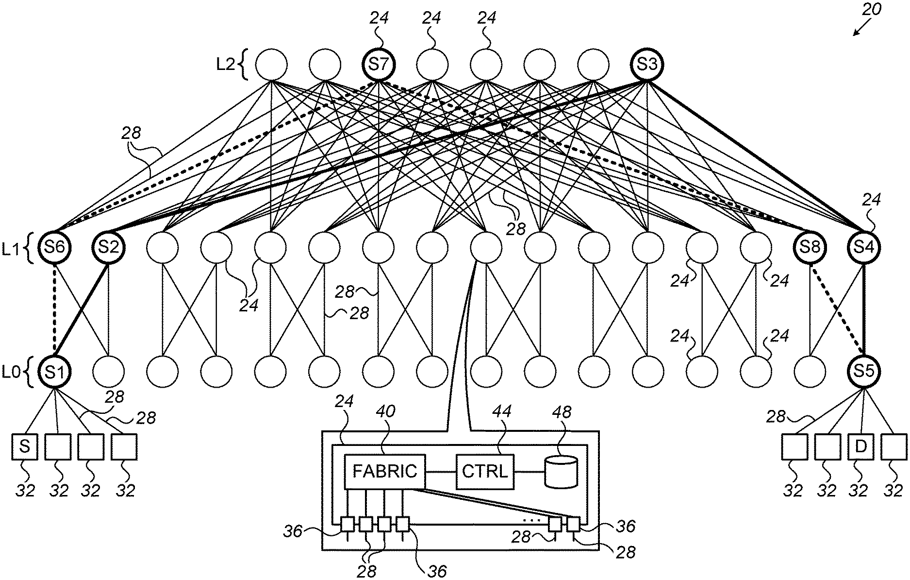
FIG. 1 is a block diagram that schematically illustrates a communication network 20, in accordance with an embodiment of the present invention. Network 20 comprises multiple network switches 24 that are interconnected by network links 28. Network 20 provides connectivity and communication services to multiple endpoints 32.
Endpoints 32, also referred to as hosts, may comprise any suitable computing platforms such as servers, workstations or personal computers. Network 20 may operate in accordance with any suitable communication protocol, such as Ethernet or Infiniband.
Switches 24 may comprise network switches, routers or any other suitable network elements that route or forward packets. In the context of the present patent application and in the claims, the terms "switch" and "network switch" refer to any such network element. In most of the embodiments described herein, including the example of FIG. 1, network 20 has a Fat-Tree (FT) topology. In the FT topology, switches 24 are arranged in two or more levels, denoted L0, L1, L2, . . . . Endpoints 32 are connected to switches 24 in the lowest level, denoted L0. This level is referred to as the leaf level. The highest level, in the present example L2, is referred to as the spine level.
An inset at the bottom of FIG. 1 shows the internal structure of switches 24. In this embodiment, each switch comprises multiple ports 36, a switch fabric 40, a control unit 44 and a memory 48. Ports 36 are connected to respective network links 28, and are configured to send and receive packets to and from the network (e.g., to or from an adjacent switch 24 or an endpoint 32). Fabric 40 is configured to forward packets between ports 36. Control unit 44 is configured to control and manage switch 24, including configuring fabric 40 to apply the desired forwarding operations. Memory 48 is configured to store forwarding tables and/or other relevant information.
The configurations of network 20 and switches 24 shown in FIG. 1 are example configurations that are depicted purely for the sake of conceptual clarity. In alternative embodiments, any other suitable network and/or switch configuration can be used. For example, although FIG. 1 shows a three-level FT network, the disclosed techniques can be used in FT networks having any other suitable number of levels. Further alternatively, the disclosed techniques are not limited to FT networks, and can be used in networks having other suitable topologies.
The different elements of switches 24 may be implemented using any suitable hardware, such as in an Application-Specific Integrated Circuit (ASIC) or Field-Programmable Gate Array (FPGA). Memory 48 may comprise, for example, a Random Access Memory (RAM), a Flash memory or other suitable type of memory. In some embodiments, some elements of switches 24 can be implemented using software, or using a combination of hardware and software elements. In the context of the present patent application and in the claims, fabric 40, control unit 44 and memory 48 are referred to as packet processing circuitry that carries out the disclosed techniques. In alternative embodiments, the packet processing circuitry can be implemented in any other suitable manner.
In some embodiments, control units 44 of switches 24 comprise general-purpose processors, which are programmed in software to carry out the functions described herein. The software may be downloaded to the processors in electronic form, over a network, for example, or it may, alternatively or additionally, be provided and/or stored on non-transitory tangible media, such as magnetic, optical, or electronic memory.
Generating Unicast Congestion Notifications
In an FT network, any route from a source endpoint to a destination endpoint comprises an "upwards" segment followed by a "downwards" segment. The upwards segment begins at the switch that serves the source endpoint in the leaf level L0, and proceeds upwards in the order of levels (but not necessarily all the way to the spine level). The downwards segment proceeds downwards in the order of levels, until reaching the switch that serves the destination endpoint in the leaf level L0.
Consider, for example, a route shown in bold in FIG. 1, from a source endpoint 32 denoted S to a destination endpoint 32 denoted D. The upwards segment of this route traverses switches denoted S1, S2 and S3. The downwards segment of this route traverses switches denoted S3, S4 and S5. Another possible route from S to D, marked with dashed lines in the figure, has an upwards segment that traverses switches denoted S1, S6 and S7, and then a downwards segment that traverses switches denoted S7, S8 and S5.
Generally, the full-FT topology has the following properties: Property I: In the upwards direction, switches always have a choice of two or more possible routes en-route to a given destination endpoint. In the downwards direction, on the other hand, a given destination endpoint is reachable from a given switch over only a single possible route. Property II: For a given destination endpoint, any routing decision taken by a switch along the upwards segment unambiguously defines the highest-level switch to be traversed, and the entire downwards segment of the route. Property III: For a given source endpoint, and for a given switch in a level X along the downward segment of a route, the upwards segment can only traverse a single possible switch in any level lower than X. In particular, for a given switch in level X along the downward segment, the upwards segment can only traverse one possible switch in level X-1. Thus, in a given switch in level X, the source address of a packet received from a higher-level switch uniquely defines the switch in level X-1 that forwarded that packet upwards. This property is based on a more fundamental property--A packet forwarded downwards via a specific switch in level X uniquely defines (for a given source address) another switch in level X via which the packet was forwarded upwards. For a specific source address, to pass via a specific switch at level X in the upward segment, there is only a single possible choice of a switch at level X-1 in the upward segment.
In some embodiments of the present invention, switches 24 carry out an adaptive routing scheme that exploits the above properties. Consider a flow of packets that originates from a source endpoint S and is destined to a destination endpoint D. The flow is initially routed through FT network 20 along a certain route having an upwards segment and a downwards segment.
In an example embodiment, a switch 24 that lies on the downwards segment of the route encounters congestion at the output port it uses to forward the flow downwards. The congestion prevents the switch from continuing to forward the packets of the flow over the current route. Since the switch in question is on the downwards segment, it cannot choose an alternative route that reaches the same destination endpoint (see PROPERTY I above).
In order to recover from this situation, the switch selects an alternative switch along the current route, and requests the alternative switch to reroute the flow. In the description that follows, the former switch is referred to as the congested switch, and the latter switch is referred to as the rerouting switch.
Because of PROPERTY I above, the rerouting switch should lie on the upwards segment of the current route, so that it will have at least one alternative routing option. In an embodiment, the congested switch is on level X of the FT network. The congested switch chooses a switch in level X-1 that lies on the upwards segment of the current route, to serve as the rerouting switch. In accordance with PROPERTY III above, only a single switch in level X-1 lies on the upwards segment of the current route, and, for a given congested switch, the identity of this rerouting switch is uniquely defined by the identity of the source endpoint (and thus by the source address of the packets in the flow).
In some embodiments, each switch 24 holds a database or any other suitable data structure that records, per source address, the identity of the switch in the next-lower level that will serve as the rerouting switch. The database is typically stored in memory 48 of the switch. Note that a given source address may be mapped to different rerouting switches in the databases of different switches. In a given switch, however, each source address is mapped to a unique respective rerouting switch.
Each switch 24 may use any suitable technique for constructing the database, i.e., for obtaining a mapping between each source address and a respective rerouting switch in the next-lower level. In one embodiment, this mapping already exists in the switch--It is the same mapping used for forwarding packets in the opposite direction to this endpoint. Alternatively, the database may be pre-programmed into each switch, or learned adaptively during operation. In some embodiments, the addressing scheme used in network 20 is location-based, in which case database 24 may be simplified.
Thus, when a need arises to reroute a flow, the congested switch queries its database with the source address of the flow, and retrieves the identity (e.g., the address) of the rerouting switch. The congested switch then generates a notification packet, referred to as "adaptive routing notification (ARN)," "congestion notification" or simply "notification." The ARN comprises a unicast packet that is addressed individually to the specific rerouting switch selected by the congested switch.
The congested switch sends the ARN to the rerouting switch. The rerouting switch receives the ARN, and in response may reroute the flow to an alternative route that reaches the destination endpoint but does not traverse the congested switch. Note that, since the ARN is addressed explicitly to the rerouting switch, it can be forwarded to the rerouting switch over any desired route, not necessarily over the reverse direction of the route of the flow.
For example, with reference to FIG. 1, consider a scenario in which switch S4 (on the downwards segment of the current route from S to D marked in bold) is the congested switch. Switch S4 is in level L1, and therefore the rerouting switch is one of the switches in level L0. In accordance with the database in switch S4, the rerouting switch is necessarily switch S1. Switch S4 thus sends an ARN to switch S1. In response, switch S1 reroutes the flow to an alternative route (shown in dashed lines) that reaches endpoint D but does not traverse the congested switch S4.
FIG. 2 is a flow chart that schematically illustrates a method for forwarding ARNs in FT network 20, in accordance with an embodiment of the present invention. The method begins with a switch 24 at level X of FT network 20 receiving from level X+1 packets of a certain flow, at a packet reception step 60. The packets originate from source endpoint S, and are to be forwarded downwards to level X-1 en-route to destination endpoint S.
At a congestion checking step 64, the switch checks for congestion at the egress port designated for forwarding the packets of the flow. If no congestion exists, the method loops back to step 60 above.
If congestion is detected, the congested switch queries its database to identify the appropriate rerouting switch in level X-1, at a rerouting identification step 68. At a notification step 72, the congested switch generates and sends a unicast ARN, which is addressed individually to the identified rerouting switch. Subsequently, the rerouting switch receives the ARN and reroutes the flow.
In the example above, a congested switch in level X of the FT network selects a rerouting switch in level X-1. In alternative embodiments, a congested switch in level X may select a rerouting switch in any level that is lower than X, e.g., in level X-2 or X-3 (if such levels exist). The latter choice of rerouting switch will also result in a route that does not traverse the congested switch, but may also reroute some additional traffic that did not traverse the congested switch in the first place.
The examples above refer mainly to a congested switch in the downstream segment. In alternative embodiments, the disclosed techniques can also be carried out in a switch that is part of the upstream segment, but is nevertheless unable to reroute the traffic locally. For example, in such a switch all possible egress ports leading to the possible alternative routes may be congested. For example, the aggregate bandwidth over the upstream ports of the switch (the ports connecting to upper-level switches) may be smaller than the aggregate bandwidth over the downstream ports (the ports connecting to lower-level switches). This scenario is sometimes referred to as oversubscription. In such an embodiment, being aware of the network topology, the congested switch may select the previous switch in the upwards segment as the rerouting switch, and send a unicast ARN to that switch.
As noted above, the disclosed techniques are not limited to full FT networks. For example, in some embodiments the disclosed techniques are implemented in a quasi-FT network. Unlike full FT, in a quasi-FT network a switch in the downwards segment of a route may have one or more options for rerouting in case of congestion on the current egress port. In such cases, the terms "congestion" or "compromised ability to forward packets" refers to congestion or compromised ability on all possible egress ports. Moreover, in a quasi-FT network, for a given congested switch and a given source address, there may exist two or more rerouting switches. Thus, in some embodiments the congested switch identifies two or more rerouting switches, and sends a respective unicast ARN to each of them.
In some embodiments, source endpoint S is connected to two or more leaf switches in level L0, for example using different ports of a multi-port Network Interface Controller (NIC) of the endpoint. This sort of configuration is sometimes referred to as Multi-chassis Link Aggregation (MLAG). When using MLAG, packets originating from the source endpoint may enter network 20 via two or more different switches, and thus traverse two or more different routes to the destination endpoint D. Therefore, in these embodiments the congested switch identifies two or more rerouting switches (one per each of the two or more current routes from S to D), and sends the ARN to each of the rerouting switches.
Although the embodiments described herein refer mainly to congestion control, the disclosed techniques can also be used for mitigating failures such as port failure or link failure. In the present context, both congestion and failure are referred to herein as "compromised ability" of a switch to forward packets to a destination endpoint. Upon detecting compromised ability to forward packets, a switch may use the disclosed techniques for identifying a rerouting switch and sending a unicast ARN to the rerouting switch.
It will be appreciated that the embodiments described above are cited by way of example, and that the present invention is not limited to what has been particularly shown and described hereinabove. Rather, the scope of the present invention includes both combinations and sub-combinations of the various features described hereinabove, as well as variations and modifications thereof which would occur to persons skilled in the art upon reading the foregoing description and which are not disclosed in the prior art. Documents incorporated by reference in the present patent application are to be considered an integral part of the application except that to the extent any terms are defined in these incorporated documents in a manner that conflicts with the definitions made explicitly or implicitly in the present specification, only the definitions in the present specification should be considered.
* * * * *
References
D00000
D00001
D00002
XML
uspto.report is an independent third-party trademark research tool that is not affiliated, endorsed, or sponsored by the United States Patent and Trademark Office (USPTO) or any other governmental organization. The information provided by uspto.report is based on publicly available data at the time of writing and is intended for informational purposes only.
While we strive to provide accurate and up-to-date information, we do not guarantee the accuracy, completeness, reliability, or suitability of the information displayed on this site. The use of this site is at your own risk. Any reliance you place on such information is therefore strictly at your own risk.
All official trademark data, including owner information, should be verified by visiting the official USPTO website at www.uspto.gov. This site is not intended to replace professional legal advice and should not be used as a substitute for consulting with a legal professional who is knowledgeable about trademark law.