Ferroresonant transformer for use in uninterruptible power supplies
Le , et al. October 27, 2
U.S. patent number 10,819,144 [Application Number 15/495,407] was granted by the patent office on 2020-10-27 for ferroresonant transformer for use in uninterruptible power supplies. This patent grant is currently assigned to ALPHA TECHNOLOGIES SERVICES, INC.. The grantee listed for this patent is Alpha Technologies Inc.. Invention is credited to Litcho Datzov, Thanh Le, James Richardson.

| United States Patent | 10,819,144 |
| Le , et al. | October 27, 2020 |
Ferroresonant transformer for use in uninterruptible power supplies
Abstract
A ferroresonant transformer assembly, which is adapted to be connected to a primary power source, an inverter system, a resonant capacitor, and at least one load, comprises a core, a main shunt, and first, second, and third windings. The main shunt is arranged to define a primary side and a secondary side of the ferroresonant transformer. The first windings are arranged on the primary side of the ferroresonant transformer and are configured to be operatively connected to the primary power source. The second windings are arranged on the secondary side of the ferroresonant transformer and are configured to be operatively connected to the inverter system. The third windings arranged on the secondary side of the ferroresonant transformer and are configured to be selectively operatively connected to or disconnected from the resonant capacitor.
| Inventors: | Le; Thanh (Ferndale, WA), Richardson; James (Bellingham, WA), Datzov; Litcho (Bellingham, WA) | ||||||||||
|---|---|---|---|---|---|---|---|---|---|---|---|
| Applicant: |
|
||||||||||
| Assignee: | ALPHA TECHNOLOGIES SERVICES,
INC. (Bellingham, WA) |
||||||||||
| Family ID: | 1000005145561 | ||||||||||
| Appl. No.: | 15/495,407 | ||||||||||
| Filed: | April 24, 2017 |
Prior Publication Data
| Document Identifier | Publication Date | |
|---|---|---|
| US 20170229906 A1 | Aug 10, 2017 | |
Related U.S. Patent Documents
| Application Number | Filing Date | Patent Number | Issue Date | ||
|---|---|---|---|---|---|
| 14071497 | Nov 4, 2013 | 9633781 | |||
| 12803787 | Nov 5, 2013 | 8575779 | |||
| 61305926 | Feb 18, 2010 | ||||
| Current U.S. Class: | 1/1 |
| Current CPC Class: | H02J 9/062 (20130101); H01F 27/28 (20130101); H01F 27/24 (20130101); H01F 38/14 (20130101); H01F 27/40 (20130101); H02J 9/067 (20200101); Y10T 29/49073 (20150115) |
| Current International Class: | H01F 27/24 (20060101); H02J 9/06 (20060101); H01F 27/40 (20060101); H01F 38/14 (20060101); H01F 27/28 (20060101) |
| Field of Search: | ;307/66 |
References Cited [Referenced By]
U.S. Patent Documents
| 352105 | November 1886 | Zipernowsky et al. |
| 375614 | December 1887 | Eickmeyer |
| 414266 | November 1889 | Thomson |
| 1718238 | June 1929 | Kettering et al. |
| 1950396 | March 1934 | Boucher |
| 2007415 | July 1935 | Walker |
| 2014101 | September 1935 | Bryan |
| 2037183 | April 1936 | Strieby |
| 2036994 | December 1936 | Frank et al. |
| 2085072 | June 1937 | Bobe |
| 2165969 | July 1939 | Humbert et al. |
| 2240123 | April 1941 | Shoup et al. |
| 2302192 | November 1942 | Dannheiser |
| 2352073 | June 1944 | Boucher et al. |
| 2427678 | September 1947 | Laging |
| 2444794 | July 1948 | Uttal et al. |
| 2512976 | June 1950 | Smeltzly |
| 2688704 | September 1954 | Christenson |
| 2856543 | October 1958 | Dixon et al. |
| 2920211 | January 1960 | Gotoh |
| 2996656 | August 1961 | Sola |
| 3022458 | February 1962 | Sola |
| 3064195 | November 1962 | Freen |
| 3221172 | November 1965 | Rolison |
| 3283165 | November 1966 | Bloch |
| 3293445 | December 1966 | Levy |
| 3304599 | February 1967 | Nordin |
| 3305762 | February 1967 | Geib, Jr. |
| 3339080 | August 1967 | Howald |
| 3345517 | October 1967 | Smith |
| 3348060 | October 1967 | Jamieson |
| 3389329 | June 1968 | Quirk et al. |
| 3435358 | March 1969 | Rheinfelder |
| 3458710 | July 1969 | Dodge |
| 3521152 | July 1970 | Emerson |
| 3525035 | August 1970 | Kakalec |
| 3525078 | August 1970 | Baggott |
| 3546571 | December 1970 | Fletcher et al. |
| 3590362 | June 1971 | Kakalec |
| 3636368 | January 1972 | Sia |
| 3678284 | July 1972 | Peters |
| 3678377 | July 1972 | Chiffert |
| 3686561 | August 1972 | Spreadbury |
| 3691393 | September 1972 | Papachristou |
| 3742251 | June 1973 | Thompson et al. |
| 3823358 | July 1974 | Rey |
| 3859589 | January 1975 | Rush |
| 3860748 | January 1975 | Everhart et al. |
| 3873846 | March 1975 | Morio et al. |
| 3909560 | September 1975 | Martin et al. |
| 3916295 | October 1975 | Hunter |
| 3938033 | February 1976 | Borkovitz et al. |
| 3943447 | March 1976 | Shomo, III |
| 4004110 | January 1977 | Whyte |
| 4010381 | March 1977 | Fickenscher et al. |
| 4122382 | October 1978 | Bernstein |
| 4130790 | December 1978 | Heisey |
| 4170761 | October 1979 | Koppehele |
| 4217533 | August 1980 | Van Beek |
| 4251736 | February 1981 | Coleman |
| 4262245 | April 1981 | Wendt |
| 4270080 | May 1981 | Kostecki |
| 4277692 | July 1981 | Small |
| 4313060 | January 1982 | Fickenscher et al. |
| 4353014 | October 1982 | Willis |
| 4366389 | December 1982 | Hussey |
| 4366390 | December 1982 | Rathmann |
| 4385263 | May 1983 | Luz et al. |
| 4400624 | August 1983 | Ebert, Jr. |
| 4400625 | August 1983 | Hussey |
| 4423379 | December 1983 | Jacobs et al. |
| 4460834 | July 1984 | Gottfried |
| 4466041 | August 1984 | Witulski et al. |
| 4472641 | September 1984 | Dickey et al. |
| 4475047 | October 1984 | Ebert, Jr. |
| 4510401 | April 1985 | Legoult |
| 4604530 | August 1986 | Shibuya |
| 4616305 | October 1986 | Damiano et al. |
| 4628426 | December 1986 | Steigerwald |
| 4631471 | December 1986 | Fouad et al. |
| 4656412 | April 1987 | McLyman |
| 4670702 | June 1987 | Yamada et al. |
| 4673825 | June 1987 | Raddi et al. |
| 4686375 | August 1987 | Gottfried |
| 4697134 | September 1987 | Burkum et al. |
| 4700122 | October 1987 | Cimino et al. |
| 4709318 | November 1987 | Gephart et al. |
| 4719427 | January 1988 | Morishita et al. |
| 4719550 | January 1988 | Powell et al. |
| 4775800 | January 1988 | Wood |
| 4724290 | February 1988 | Campbell |
| 4724478 | February 1988 | Masuko et al. |
| 4730242 | March 1988 | Divan |
| 4733223 | March 1988 | Gilbert |
| 4740739 | April 1988 | Quammen et al. |
| 4745299 | May 1988 | Eng et al. |
| 4748341 | May 1988 | Gupta |
| 4748342 | May 1988 | Dijkmans |
| 4763014 | August 1988 | Model et al. |
| 4791542 | December 1988 | Piaskowski |
| 4829225 | May 1989 | Podrazhansky et al. |
| 4860185 | August 1989 | Brewer et al. |
| 4864483 | September 1989 | Divan |
| 4882717 | November 1989 | Hayakawa et al. |
| 4885474 | December 1989 | Johnstone et al. |
| 4890213 | December 1989 | Seki |
| 4916329 | April 1990 | Dang et al. |
| 4920475 | April 1990 | Rippel |
| 4922125 | May 1990 | Casanova et al. |
| 4926084 | May 1990 | Furutsu et al. |
| 4943763 | July 1990 | Bobry |
| 4952834 | August 1990 | Okada |
| 4954741 | September 1990 | Furutsu et al. |
| 4975649 | December 1990 | Bobry |
| 4988283 | January 1991 | Nagasawa et al. |
| 5010469 | April 1991 | Bobry |
| 5017800 | May 1991 | Divan |
| 5027264 | June 1991 | DeDoncker et al. |
| 5029285 | July 1991 | Bobry |
| 5057698 | October 1991 | Widener et al. |
| 5099410 | March 1992 | Divan |
| 5137020 | August 1992 | Wayne et al. |
| 5148043 | September 1992 | Hirata et al. |
| 5154986 | October 1992 | Takechi et al. |
| 5168205 | December 1992 | Kan et al. |
| 5172009 | December 1992 | Mohan |
| 5185536 | February 1993 | Johnson, Jr. et al. |
| 5193067 | March 1993 | Sato et al. |
| 5198698 | March 1993 | Paul et al. |
| 5198970 | March 1993 | Kawabata et al. |
| 5200643 | April 1993 | Brown |
| 5224025 | June 1993 | Divan et al. |
| 5229650 | July 1993 | Kita et al. |
| 5237208 | August 1993 | Tominaga et al. |
| 5281919 | January 1994 | Palanisamy |
| 5302858 | April 1994 | Folts |
| 5334057 | August 1994 | Blackwell |
| 5400005 | March 1995 | Bobry |
| 5402053 | March 1995 | Divan et al. |
| 5410720 | April 1995 | Osterman |
| 5440179 | August 1995 | Severinsky |
| 5457377 | October 1995 | Jonsson |
| 5483463 | January 1996 | Qin et al. |
| 5532525 | July 1996 | Kaiser et al. |
| 5579197 | November 1996 | Mengelt et al. |
| 5602462 | February 1997 | Stich et al. |
| 5610451 | March 1997 | Symonds |
| 5635773 | June 1997 | Stuart |
| 5638244 | June 1997 | Mekanik et al. |
| 5642002 | June 1997 | Mekanik et al. |
| 5739595 | April 1998 | Mekanik et al. |
| 5745356 | April 1998 | Tassitino, Jr. et al. |
| 5747887 | May 1998 | Takanaga et al. |
| 5747888 | May 1998 | Zilberberg |
| 5760495 | June 1998 | Mekanik |
| 5768117 | June 1998 | Takahashi et al. |
| 5783932 | July 1998 | Mamba et al. |
| 5790391 | August 1998 | Stich et al. |
| 5804890 | September 1998 | Kakalec et al. |
| 5844327 | December 1998 | Batson |
| 5880536 | March 1999 | Mardirossian |
| 5892431 | April 1999 | Osterman |
| 5897766 | April 1999 | Kawatsu |
| 5901057 | May 1999 | Brand et al. |
| 5925476 | July 1999 | Kawatsu |
| 5961604 | October 1999 | Anderson et al. |
| 5982412 | November 1999 | Nulty |
| 5982645 | November 1999 | Levran et al. |
| 5982652 | November 1999 | Simonelli et al. |
| 5994793 | November 1999 | Bobry |
| 5994794 | November 1999 | Wehrlen |
| 6011324 | January 2000 | Kohlstruck et al. |
| 6014015 | January 2000 | Thorne et al. |
| 6028414 | February 2000 | Chouinard et al. |
| 6069412 | May 2000 | Raddi et al. |
| 6074246 | June 2000 | Seefeldt et al. |
| 6100665 | August 2000 | Alderman |
| 6198178 | March 2001 | Schienbein et al. |
| 6212081 | April 2001 | Sakai |
| 6218744 | April 2001 | Zahrte et al. |
| 6288456 | September 2001 | Crafty |
| 6288916 | September 2001 | Liu et al. |
| 6295215 | September 2001 | Faria et al. |
| 6348782 | February 2002 | Oughton, Jr. |
| 6426610 | July 2002 | Janik |
| 6433905 | August 2002 | Price et al. |
| 6465910 | October 2002 | Young et al. |
| 6486399 | November 2002 | Armstrong et al. |
| 6602627 | August 2003 | Liu et al. |
| 6738435 | May 2004 | Becker |
| 6841971 | January 2005 | Spee et al. |
| 6906933 | June 2005 | Taimela |
| 6933626 | August 2005 | Oughton |
| 7040920 | May 2006 | Johnson et al. |
| 7182632 | February 2007 | Johnson et al. |
| 7449798 | November 2008 | Suzuki et al. |
| 7567520 | July 2009 | Ostrosky |
| 8575779 | November 2013 | Le et al. |
| 9030045 | May 2015 | Richardson et al. |
| 9030048 | May 2015 | Heidenreich et al. |
| 9234916 | January 2016 | Peck et al. |
| 9633781 | April 2017 | Le et al. |
| 9812900 | November 2017 | Richardson et al. |
| 2005/0258927 | November 2005 | Lu |
| 2007/0262650 | November 2007 | Li |
| 2009/0076661 | March 2009 | Pearson et al. |
| 2009/0196082 | August 2009 | Mazumder et al. |
| 2009/0240377 | September 2009 | Batzler et al. |
| 2010/0191387 | July 2010 | Warren et al. |
| 2010/0324548 | December 2010 | Godara et al. |
| 2011/0187197 | August 2011 | Moth |
| 2011/0238345 | September 2011 | Gauthier et al. |
| 2011/0273151 | November 2011 | Lesso et al. |
| 2012/0091811 | April 2012 | Heidenreich et al. |
| 2012/0212051 | August 2012 | Heidenreich et al. |
| 2012/0217800 | August 2012 | Heidenreich et al. |
| 2012/0217806 | August 2012 | Heidenreich et al. |
| 2012/0217808 | August 2012 | Richardson et al. |
| 2013/0162650 | June 2013 | Marivoet et al. |
| 2014/0062189 | March 2014 | Le et al. |
| 2015/0241892 | August 2015 | Gaucher et al. |
| 2015/0244211 | August 2015 | Richardson et al. |
| 2017/0229906 | August 2017 | Le et al. |
| 2018/0062427 | March 2018 | Richardson et al. |
| 2019/0079571 | March 2019 | Faley et al. |
| 2019/0081479 | March 2019 | Faley et al. |
| 2858015 | Apr 2015 | EP | |||
| 005201 | Apr 1885 | GB | |||
| 260731 | Sep 1925 | GB | |||
| 2005118 | Apr 1979 | GB | |||
| 2120474 | Nov 1983 | GB | |||
| 2137033 | Mar 1984 | GB | |||
| 2171861 | Sep 1986 | GB | |||
| 2185326 | Oct 1986 | GB | |||
| 2355350 | Apr 2001 | GB | |||
| 2304335 | Aug 2007 | RU | |||
| WO 8501842 | Apr 1985 | WO | |||
| 2009094540 | Jul 2009 | WO | |||
| 2010135406 | Nov 2010 | WO | |||
| 2011103131 | Dec 2011 | WO | |||
| 2017044970 | Mar 2017 | WO | |||
| 2019014682 | Jan 2019 | WO | |||
| 2019051321 | Mar 2019 | WO | |||
| 2019051499 | Mar 2019 | WO | |||
Other References
|
European Patent Office, "Extended European Search Report", Application No. 16845289.4, dated Dec. 19, 2018, 10 pages. cited by applicant . International Searching Authority, ISR & Written Opinion, PCT/US2018/050094, dated Dec. 27, 2018, 7 pages. cited by applicant . International Searching Authority, ISR & Written Opinion, PCT/US2018/050500, dated Feb. 28, 2019, 6 pages. cited by applicant. |
Primary Examiner: Barnie; Rexford N
Assistant Examiner: Vu; Toan T
Attorney, Agent or Firm: Schacht; Michael R. Schacht Law Office, Inc.
Parent Case Text
RELATED APPLICATIONS
This application, U.S. patent application Ser. No. 15/495,407 filed Apr. 24, 2017 is a continuation of U.S. patent application Ser. No. 14/071,497, filed Nov. 4, 2013, now U.S. Pat. No. 9,633,781, which issued on Apr. 25, 2017.
U.S. patent application Ser. No. 14/071,497 is a continuation of U.S. patent application Ser. No. 12/803,787 filed Jul. 7, 2010, now U.S. Pat. No. 8,575,779 which issued Nov. 5, 2013.
U.S. patent application Ser. No. 12/803,787 claims benefit of U.S. Provisional Patent Application Ser. No. 61/305,926 filed Feb. 18, 2010, now expired.
The contents of all related applications listed above are incorporated herein by reference.
Claims
What is claimed is:
1. A ferroresonant transformer assembly adapted to be connected to a primary power source, an inverter system, a resonant capacitor, and at least one load, the ferroresonant transformer assembly comprising: a core; a main shunt arranged to define, a primary side and a secondary side of the ferroresonant transformer assembly; first windings arranged on the primary side of the ferroresonant transformer assembly, where the first windings are configured to be operatively connected to the primary power source; second windings arranged on the secondary side of the ferroresonant transformer assembly, where the second windings are configured to be operatively connected to the inverter system; and third windings arranged on the secondary side of the ferroresonant transformer assembly, the third windings are configured to be selectively operatively connected to or disconnected from the resonant capacitor; a first tap connector operatively connected to a first intermediate point of the third windings; a second tap connector operatively connected to a second intermediate point of the third windings; and a cable assembly operatively connected between a selected tap connector selected from the first and second tap connectors and at least one of a plurality of loads.
2. A ferroresonant transformer assembly as recited in claim 1, in which the cable assembly is operatively connected between the selected tap connector and a plurality of loads.
3. A ferroresonant transformer assembly as recited in claim 1, in which the main shunt is formed by an inductor.
4. A ferroresonant transformer assembly as recited in claim 1, further comprising a minor shunt arranged between the second windings and the third windings.
5. An uninterruptible power supply system adapted to be connected to a primary power source, a battery system, and at least one load, the uninterruptible power supply comprising: a ferroresonant transformer comprising a core; a main shunt arranged to define a primary side and a secondary side of the ferroresonant transformer; first windings arranged on the primary side of the ferroresonant transformer; second windings arranged on the secondary side of the ferroresonant transformer; and third windings arranged on the secondary side of the ferroresonant transformer; and an inverter, where the inverter is operatively connected to the second windings; and a resonant capacitor, where the resonant capacitor is selectively operatively connected to or disconnected from the third windings; wherein the first windings are operatively connected to the primary power source; the inverter is operatively connected to the battery system; in a line mode, the resonant capacitor is connected to the third windings and power flows from the primary source to the at least one load through the ferroresonant transformer; and in a standby mode, the resonant capacitor is disconnected from the third windings and power flows from the inverter to the at least one load through the ferroresonant transformer.
6. An uninterruptible power supply system as recited in claim 5, further comprising a select switch, where the select switch is configured to: connect the resonant capacitor to the third windings when the uninterruptible power supply is in the line mode; and disconnect the resonant capacitor from the third windings when the uninterruptible power supply is in the standby mode.
7. An uninterruptible power supply system as recited in claim 5, in which the main shunt is formed by an inductor.
8. An uninterruptible power supply system as recited in claim 5, in which the ferroresonant transformer further comprises a minor shunt arranged between the second windings and the third windings.
9. An uninterruptible power supply system as recited in claim 5, in which the inverter is pulse-width modulated.
10. An uninterruptible power supply system as recited in claim 5, in which the inverter is a switch mode power supply.
11. An uninterruptible power supply system as recited in claim 5, in which the primary power source is a utility power supply.
12. An uninterruptible power supply system as recited in claim 5, further comprising a filter capacitor operatively connected across at least a portion of the third windings.
13. A method of supplying uninterruptible power to at least one load from a primary power source and a battery system, the method comprising the steps of: providing a ferroresonant transformer comprising a core; a main shunt arranged to define a primary side and a secondary side of the ferroresonant transformer; first windings arranged on the primary side of the ferroresonant transformer; second windings arranged on the secondary side of the ferroresonant transformer; and third windings arranged on the secondary side of the ferroresonant transformer; and operatively connecting an inverter to the second windings; operatively connecting the first windings to the primary power source; operatively connecting the inverter to the battery system; in a line mode, operatively connecting a resonant capacitor to the third windings and power flows from the primary source to the at least one load through the ferroresonant transformer; and in a standby mode, disconnecting the resonant capacitor from the third windings and power flows from the inverter to the at least one load through the ferroresonant transformer.
14. A method as recited in claim 13, further comprising the steps of: providing a select switch; operating the select switch to connect the resonant capacitor to the third windings when the uninterruptible power supply is in the line mode; and operating the select switch to disconnect the resonant capacitor from the third windings when the uninterruptible power supply is in the standby mode.
15. A method as recited in claim 13, in which the step of providing the ferroresonant transformer comprises the step of arranging an inductor to form the main shunt.
16. A method as recited in claim 13, in which the step of providing the ferroresonant transformer comprises the step of arranging a minor shunt the second windings and the third windings.
17. A method as recited in claim 13, in which the step of providing the inverter comprises the step of providing a pulse-width modulated inverter.
18. A method as recited in claim 13, in which the step of providing the inverter comprises the step of providing a switch mode power supply.
19. A method as recited in claim 13, in which the step of operatively connecting the first windings to the primary power source comprises the step of operatively connecting the first windings to a utility power supply.
20. A method as recited in claim 13, further comprising the step of operatively connecting a filter capacitor across at least a portion of the third windings.
Description
TECHNICAL FIELD
The present invention relates the generation of a standby power signal and, more specifically, to uninterruptible power supply systems and methods using ferroresonant transformers.
BACKGROUND
Uninterruptible power supplies (UPS's) have long been used to provide at least temporary auxiliary power to electronic devices. Typically, a UPS is configured to switch between a primary power source and a standby power source as necessary to maintain constant power to a load.
For example, the primary power source may be a utility power supply, and the standby power source may take the form of a battery system. The UPS will normally operate in a line mode in which the utility power signal is passed to the load when the utility power signal is within predefined parameters. In the line mode, the UPS will typically also charge the battery system. When the utility power falls outside of the predefined parameters, the UPS will switch to standby mode in which an AC signal is generated based on the energy stored in the battery system.
A class of UPS's employs a ferroresonant transformer. A ferroresonant transformer is a saturating transformer that employs a tank circuit comprised of a resonant winding and capacitor to produce a nearly constant average output even if the input to the transformer varies. A typical UPS employing a ferroresonant transformer takes advantage of the voltage regulating properties of a ferroresonant transformer in both line and standby modes. In the context of a UPS, a ferroresonant transformer thus provides surge suppression, isolation, short circuit protection, and voltage regulation without the use of active components.
Conventionally, a ferroresonant transformer configured for use in a UPS system includes a core and an inductor arranged relative to the core to define: (a) a primary or input side of the transformer and (b) a secondary or output side of the transformer. A conventional ferroresonant transformer used in a UPS will further comprise input windings and inverter (resonant) windings arranged on the primary or input side and output windings on the secondary or output side.
An object of the present invention is to provide improved ferroresonant transformers for use in UPS systems.
SUMMARY
The present invention may be embodied as a ferroresonant transformer assembly, which is adapted to be connected to a primary power source, an inverter system, a resonant capacitor, and at least one load, comprises a core, a main shunt, and first, second, and third windings. The main shunt is arranged to define a primary side and a secondary side of the ferroresonant transformer. The first windings are arranged on the primary side of the ferroresonant transformer and are configured to be operatively connected to the primary power source. The second windings are arranged on the secondary side of the ferroresonant transformer and are configured to be operatively connected to the inverter system. The third windings arranged on the secondary side of the ferroresonant transformer and are configured to be selectively operatively connected to or disconnected from the resonant capacitor.
The present invention may also be embodied as an uninterruptible power supply system adapted to be connected to a primary power source, a battery system, and at least one load. In this example, the uninterruptible power supply comprises a ferroresonant transformer, an inverter, and a resonant capacitor. The ferroresonant transformer comprises a core, a main shunt, and first, second, and third windings. The main shunt is arranged to define a primary side and a secondary side of the ferroresonant transformer. The first windings are arranged on the primary side of the ferroresonant transformer. The second windings are arranged on the secondary side of the ferroresonant transformer. The third windings are arranged on the secondary side of the ferroresonant transformer. The inverter is operatively connected to the second windings. The resonant capacitor is selectively operatively connected to or disconnected from the third windings. The first windings are operatively connected to the primary power source. The inverter is operatively connected to the battery system. In a line mode, the resonant capacitor is connected to the third windings and power flows from the primary source to the at least one load through the ferroresonant transformer. In a standby mode, the resonant capacitor is disconnected from the third windings and power flows from the inverter to the at least one load through the ferroresonant transformer.
The present invention may also be embodied as a method of supplying uninterruptible power to at least one load from a primary power source and a battery system comprising the following steps. A ferroresonant transformer comprising a core, a main shunt, and first, second, and third windings is provided. The main shunt is arranged to define a primary side and a secondary side of the ferroresonant transformer. The first windings are arranged on the primary side of the ferroresonant transformer. The second windings are arranged on the secondary side of the ferroresonant transformer. The third windings arranged on the secondary side of the ferroresonant transformer. An inverter is operatively connected to the second windings. The first windings are operatively connected to the primary power source. The inverter is operatively connected to the battery system. In a line mode, a resonant capacitor is operatively connected to the third windings and power flows from the primary source to the at least one load through the ferroresonant transformer. In a standby mode, the resonant capacitor is disconnected from the third windings and power flows from the inverter to the at least one load through the ferroresonant transformer.
DESCRIPTION OF THE DRAWINGS
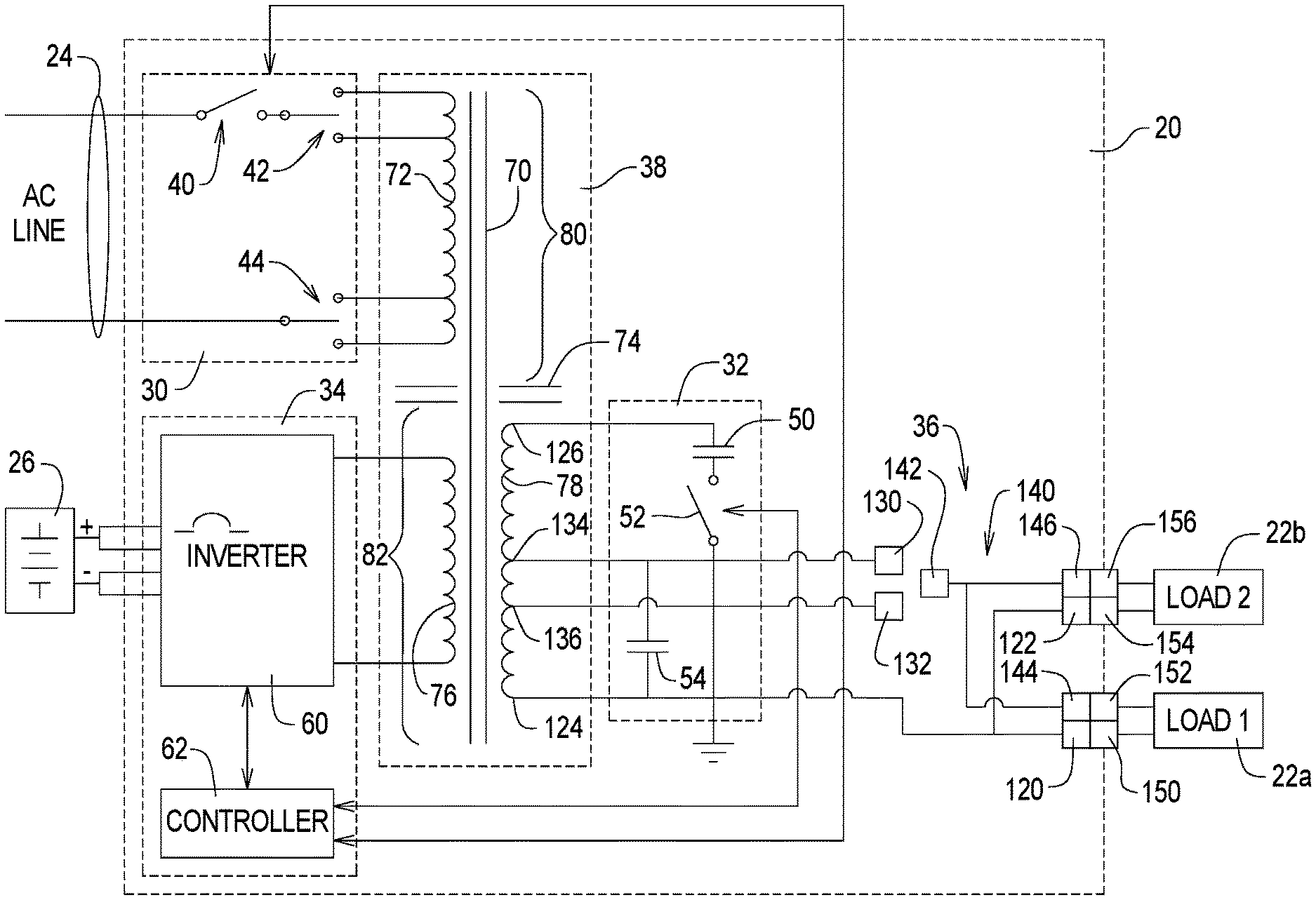
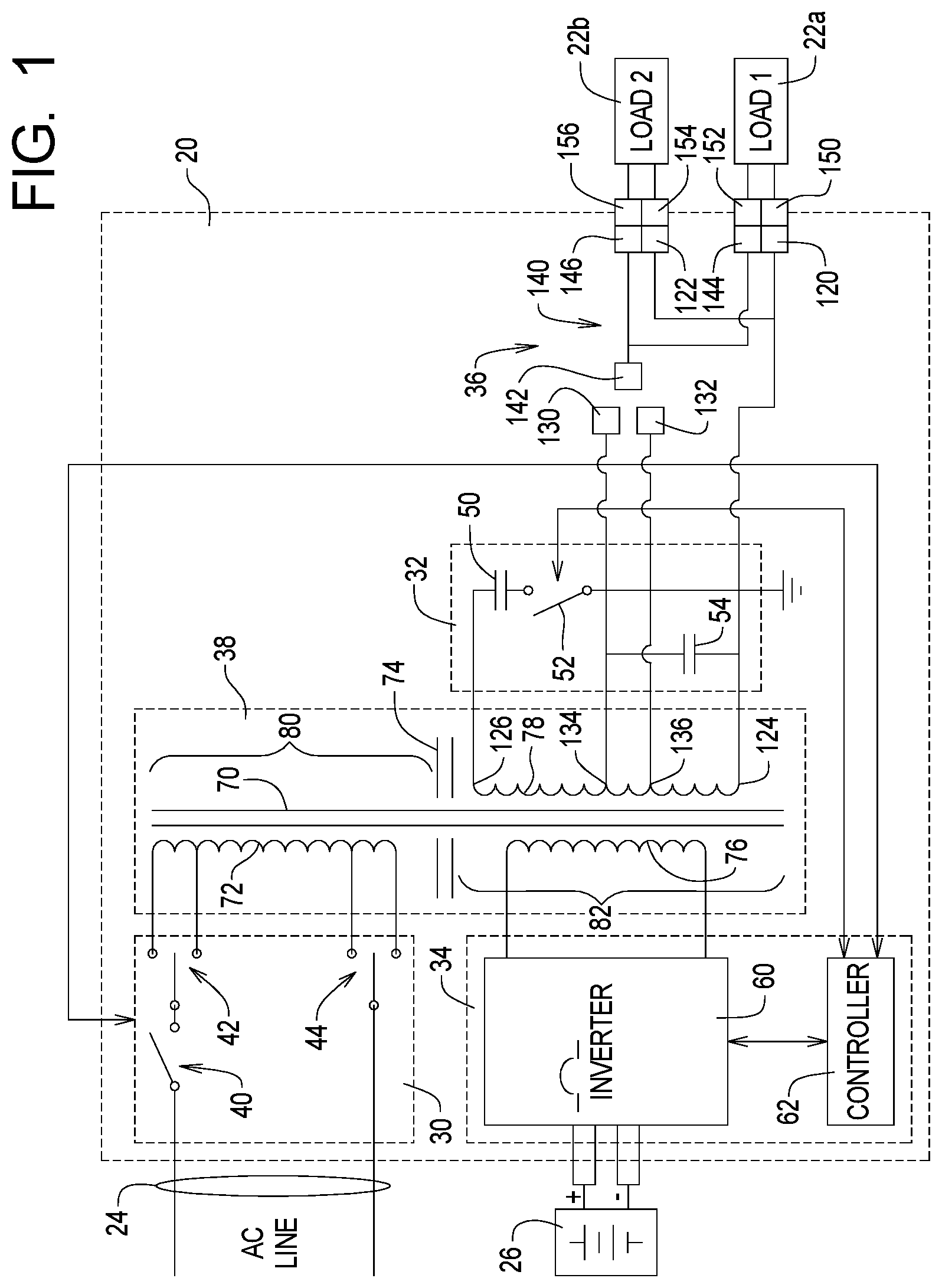
FIG. 1 is a simplified block diagram of a first embodiment of an uninterruptible power supply system using a ferroresonant transformer system constructed in accordance with, and embodying, the principles of the present invention;
FIG. 2 is a somewhat schematic view of a ferroresonant transformer forming a part of the UPS system depicted in FIG. 1;
FIG. 3 is a perspective view of the ferroresonant transformer depicted in FIG. 2;
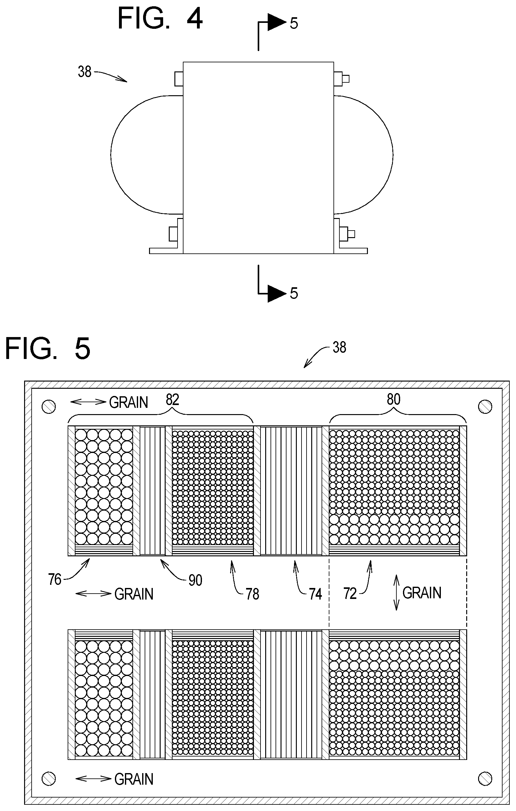
FIG. 4 is a side elevation view of the ferroresonant transformer depicted in FIGS. 2 and 3; and
FIG. 5 is a section view taken along lines 5-5 in FIG. 4.
DETAILED DESCRIPTION
Referring initially to FIG. 1 of the drawing, depicted therein is a first example of an uninterruptible power supply (UPS) system 20 constructed in accordance with, and embodying, the principles of the present invention.
The example UPS system 20 supplies power to a load 22 based on a primary power signal present on an AC power line 24 (line mode) or a secondary power signal generated by a battery pack 26 (standby mode). While the example secondary power signal is generated by a battery pack in the example UPS system 20, alternative power sources such as generators, fuel cells, solar cells, and the like may be used as the secondary power source.
The example UPS system 20 comprises an input section 30, an output section 32, an inverter section 34, a cable assembly 36, and a ferroresonant transformer 38.
The example input section 30 comprises a main switch 40 and first and second select switches 42 and 44. The example output section 32 comprises an output or resonant capacitor 50 and, optionally, a select switch 52 and a filter capacitor 54.
When the select switch 52 is closed, the output capacitor 50 forms a resonant or tank circuit with the transformer 38 as will be described in further detail below. When the select switch 52 is open, the output capacitor 50 is removed from the circuit formed by the output section 32 and transformer 38, and the filter capacitor 54 filters the output of this circuit.
The inverter section 34 comprises an inverter circuit 60. The inverter circuit 60 may be an H-bridge circuit or any other circuit capable of producing an appropriate AC power signal based on a DC power signal obtained from the battery pack 26. In particular, the inverter circuit 60 is pulse-width modulated, and the inverter section 34 functions as a switch mode power supply when the UPS system operates in the standby mode. The inverter section 34 and the inverter circuit 60 are or may be conventional and will not be described herein in further detail.
A controller 62 may be optionally included in the inverter section 34. If used, the controller 62 operates the switches 40 and 52 and controls the inverter circuit 60. The controller 62 may further control the charging of the battery pack 26 when the UPS system 20 operates in line mode based on the temperature, voltage, and/or current signals associated with the battery pack 26.
The ferroresonant transformer 38 comprises a core 70, input windings 72, an inductor 74, inverter windings 76, and output windings 78. The core 70 is or may be a conventional laminate structure. As shown in FIG. 2, the inductor 74 defines a primary side 80 and a secondary side 82 of the transformer 38. In the example transformer 38, only the input windings 72 are on the primary side 80 of the transformer 38. The inverter windings 76 and output windings 78 are on the secondary side 82 of the transformer 38. In particular, the output windings 78 are arranged between the inverter windings 76 and the inductor 74, and the inductor 74 is arranged between the output windings 78 and the input windings 72.
As perhaps best shown in FIGS. 3 and 5, the transformer 38 depicted in FIGS. 1 and 2 defines the following arrangement of windings and shunts: the input windings 72, a large (or main) shunt formed by the inductor 74, output windings 78, and inverter windings 76. FIGS. 3 and 5 further illustrate that, in the example transformer 38, a small (or minor) shunt 90 is arranged between the output windings 78 and the inverter windings 76. The small shunt 90 does not significantly affect the electromagnetic properties of the transformer 38 in the context of the overall UPS system 20 but is used in the example transformer 38 to allow the transformer 38 to operate as described herein in the context of the UPS system 20.
In the line mode, the AC power line 24 forms a primary power source that causes a primary signal to be present on the input windings 72. The input windings 72 are electromagnetically coupled to the output windings 78 such that a first output signal is supplied to one or both of the loads 22a and 22b when the UPS system 20 operates in the line mode.
In the standby mode, the battery pack 26 and inverter section 34 form a secondary power source that causes a secondary signal to be present on the inverter windings 76. The inverter windings 76 are electromagnetically coupled to the output windings 78 such that a second output signal is supplied to one or both of the loads 22a and 22b when the UPS system 20 operates in the standby mode.
The construction details of the transformer 38 are not critical to the general principles of the present invention and will depend upon a particular implementation of the UPS system 20 in which the transformer 38 is designed to operate. The example transformer 38 has the following characteristics:
TABLE-US-00001 stacking 3 .times. 3 interleaved stack height approximately 109.73 MM (4.32'') shunts positioned in cores such that there is equal overhang on both sides keeper cut from E lamination at both ends of stack; tape tightly across keeper after E-I compaction to reduce noise lamination compact E-I lamination together without air gap sleevings nylon sleevings used with bolts shims use wood shims to fill in gaps between windings and core small shunt approximately 2.00 mm (0.075'') thick (4 pcs grade H50 or 3 pcs M54 shunt lamination); polyester tape large shunt approximately 16 mm (0.625'') thick (stack height adjusted to meet short circuit current requirement); polyester tape core E-I lamination; grain orientation as shown in FIG. 3 varnish penetrate at least 80% of the windings and be fully cured
The example cable assembly 36 connects the output section 32 to one of first and second example loads 22a or 22b. In particular, the cable assembly 36 comprises first and second winding connectors 120 and 122 operatively connected to a first end 124 of the output windings 78. A second end 126 of the output windings 78 is connected to the output capacitor 50. The cable assembly 36 further comprises first and second tap connectors 130 and 132 operatively connected to first and second intermediate points 134 and 136, respectively, of the output windings 78. The example cable assembly 36 additionally comprises a selection cable 140 comprising a selection connector 142 and first and second output connectors 144 and 146. The first load 22a comprises first and second load connectors 150 and 152, while the second load 22b comprises second and third load connectors 154 and 156.
Using the example cable assembly 36, the selection connector 142 is connected to either the first tap connector 130 or the second tap connector 132 depending upon the voltage requirements of the loads 22a and 22b. The first and third load connectors 150 and 154 are connected to the first and second winding connectors 120 and 122, and the second and fourth winding connectors 152 and 156 are connected to the first and second output connectors 144 and 146, respectively. The cable assembly 36 thus allows one or both of the loads 22a and 22b to be connected to the output section 32 and the output windings 78 and, more specifically, to an appropriate portion of the output windings 78 as determined by the first and second tap connectors 130 and 132. The selection of the appropriate tap connector 130 or 132 is based on the voltage requirements of the loads 22a and 22b.
Given the foregoing, it should be apparent that the principles of the present invention may be embodied in forms other than those described above. The scope of the present invention should thus be determined the claims to be appended hereto and not the foregoing detailed description of the invention.
* * * * *
D00000
D00001
D00002
D00003
XML
uspto.report is an independent third-party trademark research tool that is not affiliated, endorsed, or sponsored by the United States Patent and Trademark Office (USPTO) or any other governmental organization. The information provided by uspto.report is based on publicly available data at the time of writing and is intended for informational purposes only.
While we strive to provide accurate and up-to-date information, we do not guarantee the accuracy, completeness, reliability, or suitability of the information displayed on this site. The use of this site is at your own risk. Any reliance you place on such information is therefore strictly at your own risk.
All official trademark data, including owner information, should be verified by visiting the official USPTO website at www.uspto.gov. This site is not intended to replace professional legal advice and should not be used as a substitute for consulting with a legal professional who is knowledgeable about trademark law.