90-degree interlocking geometry for introducer for facilitating deployment of microwave radiating catheter
Brannan , et al. October 27, 2
U.S. patent number 10,813,692 [Application Number 15/426,230] was granted by the patent office on 2020-10-27 for 90-degree interlocking geometry for introducer for facilitating deployment of microwave radiating catheter. This patent grant is currently assigned to COVIDIEN LP. The grantee listed for this patent is COVIDIEN LP. Invention is credited to Joseph D. Brannan, Eric W. Larson.


View All Diagrams
| United States Patent | 10,813,692 |
| Brannan , et al. | October 27, 2020 |
90-degree interlocking geometry for introducer for facilitating deployment of microwave radiating catheter
Abstract
A microwave ablation system includes a first cannula, a trocar insertable through the first cannula and configured to facilitate insertion of the first cannula into a target tissue, and a microwave antenna assembly configured to interlock with the first cannula, the microwave antenna assembly including a coaxial feedline having a radiating section formed thereon, the microwave antenna configured to be inserted into the first cannula. The microwave ablation system further includes an actuator operatively connected to one of the first cannula or microwave antenna assembly. Operation of the actuator between a first position and a second position exposes the radiating section of the microwave antenna assembly from a distal portion of the first cannula.
| Inventors: | Brannan; Joseph D. (Lyons, CO), Larson; Eric W. (Littleton, CO) | ||||||||||
|---|---|---|---|---|---|---|---|---|---|---|---|
| Applicant: |
|
||||||||||
| Assignee: | COVIDIEN LP (Mansfield,
MA) |
||||||||||
| Family ID: | 1000005139625 | ||||||||||
| Appl. No.: | 15/426,230 | ||||||||||
| Filed: | February 7, 2017 |
Prior Publication Data
| Document Identifier | Publication Date | |
|---|---|---|
| US 20170245930 A1 | Aug 31, 2017 | |
Related U.S. Patent Documents
| Application Number | Filing Date | Patent Number | Issue Date | ||
|---|---|---|---|---|---|
| 62301255 | Feb 29, 2016 | ||||
| Current U.S. Class: | 1/1 |
| Current CPC Class: | A61B 18/1815 (20130101); A61B 2018/00011 (20130101); A61B 2018/1869 (20130101); A61B 2018/00577 (20130101); A61B 2018/00023 (20130101); A61B 2018/00184 (20130101) |
| Current International Class: | A61B 18/18 (20060101); A61B 18/00 (20060101) |
| Field of Search: | ;606/33-41 |
References Cited [Referenced By]
U.S. Patent Documents
| D223367 | April 1972 | Kountz |
| D263020 | February 1982 | Rau, III |
| D266842 | November 1982 | Villers et al. |
| D278306 | April 1985 | McIntosh |
| 4583589 | April 1986 | Kasevich |
| D295893 | May 1988 | Sharkany et al. |
| D295894 | May 1988 | Sharkany et al. |
| 4846171 | July 1989 | Kauphusman et al. |
| 5301687 | April 1994 | Wong et al. |
| 5342357 | August 1994 | Nardella |
| 5342393 | August 1994 | Stack |
| 5364392 | November 1994 | Warner et al. |
| 5370644 | December 1994 | Langberg |
| D354218 | January 1995 | Van de Peer |
| 5413571 | May 1995 | Katsaros et al. |
| 5529067 | June 1996 | Larsen et al. |
| 5540715 | July 1996 | Katsaros et al. |
| 5545137 | August 1996 | Rudie et al. |
| 5582617 | December 1996 | Klieman et al. |
| 5603697 | February 1997 | Grundy et al. |
| 5624392 | April 1997 | Saab |
| 5630833 | May 1997 | Katsaros et al. |
| 5649959 | July 1997 | Hannam et al. |
| 5685839 | November 1997 | Edwards et al. |
| 5693082 | December 1997 | Warner et al. |
| 5741249 | April 1998 | Moss et al. |
| 5817119 | October 1998 | Klieman et al. |
| 5846248 | December 1998 | Chu et al. |
| 5974343 | October 1999 | Brevard et al. |
| 5980505 | November 1999 | Wilson |
| 5993447 | November 1999 | Blewett et al. |
| 5995875 | November 1999 | Blewett et al. |
| 6014581 | January 2000 | Whayne et al. |
| 6026331 | February 2000 | Feldberg et al. |
| D424693 | May 2000 | Pruter |
| D424694 | May 2000 | Tetzlaff et al. |
| D425201 | May 2000 | Tetzlaff et al. |
| 6061551 | May 2000 | Sorrells et al. |
| 6066139 | May 2000 | Ryan et al. |
| 6068627 | May 2000 | Orszulak et al. |
| 6099550 | August 2000 | Yoon |
| 6106524 | August 2000 | Eggers et al. |
| 6117101 | September 2000 | Diederich et al. |
| 6139527 | October 2000 | Laufer et al. |
| 6186978 | February 2001 | Samson et al. |
| 6188355 | February 2001 | Gilboa |
| 6210367 | April 2001 | Carr |
| 6221039 | April 2001 | Durgin et al. |
| 6235024 | May 2001 | Tu |
| 6239724 | May 2001 | Doron et al. |
| 6277113 | August 2001 | Berube |
| D449886 | October 2001 | Tetzlaff et al. |
| 6352503 | March 2002 | Matsui et al. |
| 6355016 | March 2002 | Bagaoisan et al. |
| 6375634 | April 2002 | Carroll |
| D457958 | May 2002 | Dycus et al. |
| D457959 | May 2002 | Tetzlaff et al. |
| 6398781 | June 2002 | Goble et al. |
| 6413255 | July 2002 | Stern |
| 6419680 | July 2002 | Cosman et al. |
| 6427089 | July 2002 | Knowlton |
| 6485486 | November 2002 | Trembly et al. |
| 6496737 | December 2002 | Rudie et al. |
| 6496738 | December 2002 | Carr |
| 6514249 | February 2003 | Maguire et al. |
| 6527753 | March 2003 | Sekine et al. |
| 6547788 | April 2003 | Maguire et al. |
| 6575969 | June 2003 | Rittman, III et al. |
| 6599288 | July 2003 | Maguire et al. |
| 6629951 | October 2003 | Laufer et al. |
| 6629974 | October 2003 | Penny et al. |
| 6635055 | October 2003 | Cronin |
| 6645234 | November 2003 | Evans et al. |
| 6652515 | November 2003 | Maguire et al. |
| 6676657 | January 2004 | Wood |
| D487039 | February 2004 | Webster et al. |
| 6689127 | February 2004 | Gough et al. |
| 6706040 | March 2004 | Mahon et al. |
| 6723091 | April 2004 | Goble et al. |
| 6740108 | May 2004 | Just et al. |
| 6770070 | August 2004 | Balbierz |
| 6773409 | August 2004 | Truckai et al. |
| 6780183 | August 2004 | Jimenez, Jr. et al. |
| 6786905 | September 2004 | Swanson et al. |
| D496997 | October 2004 | Dycus et al. |
| D499181 | November 2004 | Dycus et al. |
| 6869431 | March 2005 | Maguire et al. |
| 6893436 | May 2005 | Woodard et al. |
| 6898454 | May 2005 | Atalar et al. |
| 6932776 | August 2005 | Carr |
| 6997925 | February 2006 | Maguire et al. |
| 7004938 | February 2006 | Ormsby et al. |
| 7047063 | May 2006 | Burbank et al. |
| 7047068 | May 2006 | Haissaguerre |
| D525361 | July 2006 | Hushka |
| 7089063 | August 2006 | Lesh et al. |
| 7113832 | September 2006 | Longo |
| D531311 | October 2006 | Guerra et al. |
| D533942 | December 2006 | Kerr et al. |
| D535027 | January 2007 | James et al. |
| 7179255 | February 2007 | Lettice et al. |
| 7197356 | March 2007 | Carr |
| D541418 | April 2007 | Schechter et al. |
| 7200445 | April 2007 | Dalbec et al. |
| D541938 | May 2007 | Kerr et al. |
| 7233820 | June 2007 | Gilboa |
| 7261001 | August 2007 | Heijnsdijk et al. |
| 7263398 | August 2007 | Carr |
| 7285116 | October 2007 | de la Rama et al. |
| 7294125 | November 2007 | Phalen et al. |
| 7294127 | November 2007 | Leung et al. |
| 7300436 | November 2007 | Penny et al. |
| 7303558 | December 2007 | Swanson |
| 7318823 | January 2008 | Sharps et al. |
| D564662 | March 2008 | Moses et al. |
| 7387626 | June 2008 | Edwards et al. |
| 7402168 | July 2008 | Sanderson et al. |
| 7410486 | August 2008 | Fuimaono et al. |
| D576932 | September 2008 | Strehler |
| 7467015 | December 2008 | van der Weide |
| 7507229 | March 2009 | Hewitt et al. |
| D594736 | June 2009 | Esjunin |
| D594737 | June 2009 | Kelly et al. |
| 7559916 | July 2009 | Smith et al. |
| 7608056 | October 2009 | Kennedy, II |
| 7611508 | November 2009 | Yang et al. |
| D606203 | December 2009 | Husheer et al. |
| D613412 | April 2010 | DeCarlo |
| 7713259 | May 2010 | Gosiengfiao et al. |
| 7734330 | June 2010 | Carr |
| 7769469 | August 2010 | Carr et al. |
| 7771425 | August 2010 | Dycus et al. |
| 7783336 | August 2010 | Macfarlane et al. |
| 7850685 | December 2010 | Kunis et al. |
| 7871406 | January 2011 | Nields et al. |
| 7879031 | February 2011 | Peterson |
| 7879033 | February 2011 | Sartor et al. |
| D634010 | March 2011 | DeCarlo |
| 7921855 | April 2011 | Danek et al. |
| 7933660 | April 2011 | Carr |
| 7993351 | August 2011 | Worley et al. |
| 8027712 | September 2011 | Sioshansi et al. |
| 8152795 | April 2012 | Farr et al. |
| 8155416 | April 2012 | Nields et al. |
| 8181995 | May 2012 | DeCarlo |
| 8182466 | May 2012 | Stehr et al. |
| 8224424 | July 2012 | Burbank et al. |
| 8226566 | July 2012 | Nita |
| 8251987 | August 2012 | Willyard |
| 8280486 | October 2012 | Miller et al. |
| 8287463 | October 2012 | Field et al. |
| 8289551 | October 2012 | Wu |
| 8292881 | October 2012 | Brannan et al. |
| 8303581 | November 2012 | Arts et al. |
| 8306602 | November 2012 | Sirimanne et al. |
| 8340740 | December 2012 | Holzer et al. |
| D681810 | May 2013 | DeCarlo |
| 8476242 | July 2013 | Mon |
| 8480665 | July 2013 | DeCarlo |
| 8494246 | July 2013 | Trumer et al. |
| 8545496 | October 2013 | Arts et al. |
| 8597291 | December 2013 | Arts et al. |
| 8632461 | January 2014 | Glossop |
| 8655454 | February 2014 | Prakash et al. |
| 8768485 | July 2014 | Hancock et al. |
| 8795268 | August 2014 | Willyard |
| 8852180 | October 2014 | Brannan |
| 8892185 | November 2014 | Chi Sing et al. |
| 8906008 | December 2014 | Brannan et al. |
| 8920410 | December 2014 | Brannan |
| 8945113 | February 2015 | Brannan et al. |
| 8951225 | February 2015 | Evard et al. |
| 8968290 | March 2015 | Brannan et al. |
| 8968300 | March 2015 | Brannan |
| 9017328 | April 2015 | Bahney |
| 9044254 | June 2015 | Ladtkow et al. |
| 9066681 | June 2015 | Arts et al. |
| 9119650 | September 2015 | Brannan et al. |
| 9161814 | October 2015 | Brannan et al. |
| 9168178 | October 2015 | Reid, Jr. et al. |
| 9192308 | November 2015 | Brannan et al. |
| 9192426 | November 2015 | Brannan et al. |
| 9192439 | November 2015 | Dunning et al. |
| 9192440 | November 2015 | Rossetto |
| 9247992 | February 2016 | Ladtkow et al. |
| 9247993 | February 2016 | Ladtkow et al. |
| 9259269 | February 2016 | Ladtkow et al. |
| 9301723 | April 2016 | Brannan et al. |
| 9332959 | May 2016 | Arts et al. |
| 9358067 | June 2016 | Lee et al. |
| 9364278 | June 2016 | DeCarlo et al. |
| 9370392 | June 2016 | Sharonov |
| 9370398 | June 2016 | Ladtkow et al. |
| 9375196 | June 2016 | Zheng et al. |
| 9375283 | June 2016 | Arts et al. |
| 9439712 | September 2016 | Sharonov |
| 9498286 | November 2016 | Brannan et al. |
| 9504524 | November 2016 | Behnke, II |
| 9522033 | December 2016 | Brannan |
| 9526568 | December 2016 | Ohri et al. |
| 9549757 | January 2017 | Arts et al. |
| 2001/0056289 | December 2001 | Sippensgroenewegen |
| 2002/0022835 | February 2002 | Lee |
| 2002/0022836 | February 2002 | Goble et al. |
| 2002/0026187 | February 2002 | Swanson |
| 2002/0040185 | April 2002 | Atalar et al. |
| 2002/0042564 | April 2002 | Cooper et al. |
| 2002/0049370 | April 2002 | Laufer et al. |
| 2003/0028095 | February 2003 | Tulley et al. |
| 2003/0060813 | March 2003 | Loeb et al. |
| 2003/0191451 | October 2003 | Gilmartin |
| 2003/0212394 | November 2003 | Pearson et al. |
| 2004/0030262 | February 2004 | Fisher et al. |
| 2004/0049254 | March 2004 | Longo |
| 2004/0073238 | April 2004 | Makower |
| 2004/0082860 | April 2004 | Haissaguerre |
| 2004/0097805 | May 2004 | Verard et al. |
| 2004/0133254 | July 2004 | Sterzer et al. |
| 2004/0176740 | September 2004 | Chouinard |
| 2005/0015081 | January 2005 | Turovskiy et al. |
| 2005/0043713 | February 2005 | Zhou |
| 2005/0080333 | April 2005 | Piron et al. |
| 2005/0080334 | April 2005 | Willis |
| 2005/0096502 | May 2005 | Khalili |
| 2005/0113640 | May 2005 | Saadat et al. |
| 2005/0215942 | September 2005 | Abrahamson et al. |
| 2005/0245919 | November 2005 | van der Welde |
| 2005/0245920 | November 2005 | Vitullo et al. |
| 2005/0273006 | December 2005 | Stewart et al. |
| 2006/0004351 | January 2006 | Arless et al. |
| 2006/0009833 | January 2006 | Chobotov et al. |
| 2006/0089637 | April 2006 | Werneth et al. |
| 2006/0100614 | May 2006 | Long |
| 2006/0155270 | July 2006 | Hancock et al. |
| 2006/0167416 | July 2006 | Mathis et al. |
| 2006/0173280 | August 2006 | Goosen et al. |
| 2006/0241564 | October 2006 | Corcoran et al. |
| 2006/0253102 | November 2006 | Nance et al. |
| 2006/0253126 | November 2006 | Bjerken et al. |
| 2006/0258955 | November 2006 | Hoffman et al. |
| 2007/0027385 | February 2007 | Brister et al. |
| 2007/0032723 | February 2007 | Glossop |
| 2007/0060944 | March 2007 | Boldenow et al. |
| 2007/0077230 | April 2007 | Mon |
| 2007/0088319 | April 2007 | Martone |
| 2007/0129717 | June 2007 | Brown et al. |
| 2007/0185554 | August 2007 | Appling et al. |
| 2007/0208301 | September 2007 | Evard et al. |
| 2007/0282319 | December 2007 | van der Weide et al. |
| 2007/0287912 | December 2007 | Khuri-Yakub et al. |
| 2007/0299353 | December 2007 | Harlev et al. |
| 2008/0033286 | February 2008 | Whitmore et al. |
| 2008/0033424 | February 2008 | van der Weide et al. |
| 2008/0091169 | April 2008 | Heideman et al. |
| 2008/0147056 | June 2008 | van der Weide et al. |
| 2008/0208031 | August 2008 | Kurpad et al. |
| 2008/0208039 | August 2008 | Kurpad et al. |
| 2008/0228167 | September 2008 | Mittermeyer et al. |
| 2008/0255507 | October 2008 | Mushtaha |
| 2008/0262342 | October 2008 | Averbruch |
| 2008/0262472 | October 2008 | Lunn et al. |
| 2008/0269601 | October 2008 | Schwamb |
| 2009/0018403 | January 2009 | Black et al. |
| 2009/0076409 | March 2009 | Wu et al. |
| 2009/0076498 | March 2009 | Saadat et al. |
| 2009/0080604 | March 2009 | Shores et al. |
| 2009/0187180 | July 2009 | Brannan |
| 2009/0216115 | August 2009 | Seiler et al. |
| 2009/0222002 | September 2009 | Bonn et al. |
| 2009/0234220 | September 2009 | Maschke |
| 2009/0259105 | October 2009 | Miyano et al. |
| 2009/0295674 | December 2009 | Bonn |
| 2009/0312754 | December 2009 | Lenihan et al. |
| 2010/0004631 | January 2010 | Zhou |
| 2010/0036369 | February 2010 | Hancock |
| 2010/0053015 | March 2010 | Willyard |
| 2010/0076424 | March 2010 | Carr |
| 2010/0121319 | May 2010 | Chu et al. |
| 2010/0160719 | June 2010 | Kassab et al. |
| 2010/0185191 | July 2010 | Carr et al. |
| 2010/0234726 | September 2010 | Sirimanne et al. |
| 2010/0249754 | September 2010 | Griffin et al. |
| 2010/0256621 | October 2010 | Babkin et al. |
| 2010/0262134 | October 2010 | Jensen et al. |
| 2010/0268196 | October 2010 | Hastings et al. |
| 2010/0305559 | December 2010 | Brannan et al. |
| 2010/0312096 | December 2010 | Guttman et al. |
| 2011/0004205 | January 2011 | Chu et al. |
| 2011/0009895 | January 2011 | Gertner |
| 2011/0029049 | February 2011 | Vertikov et al. |
| 2011/0034913 | February 2011 | Brannan |
| 2011/0034917 | February 2011 | Brannan |
| 2011/0040300 | February 2011 | Brannan |
| 2011/0046622 | February 2011 | McAuley |
| 2011/0054458 | March 2011 | Behnke |
| 2011/0060326 | March 2011 | Smith et al. |
| 2011/0077634 | March 2011 | Brannan |
| 2011/0077635 | March 2011 | Bonn |
| 2011/0077638 | March 2011 | Brannan |
| 2011/0085720 | April 2011 | Barak et al. |
| 2011/0118721 | May 2011 | Brannan |
| 2011/0118723 | May 2011 | Turner et al. |
| 2011/0130750 | June 2011 | Ormsby et al. |
| 2011/0166518 | July 2011 | Nguyen et al. |
| 2011/0166519 | July 2011 | Nguyen et al. |
| 2011/0200171 | August 2011 | Beetel et al. |
| 2011/0238083 | September 2011 | Moll et al. |
| 2011/0282336 | November 2011 | Brannan et al. |
| 2011/0301587 | December 2011 | Deem et al. |
| 2011/0319880 | December 2011 | Prakash et al. |
| 2012/0029359 | February 2012 | Sterzer et al. |
| 2012/0029503 | February 2012 | Bonn |
| 2012/0035603 | February 2012 | Lenihan |
| 2012/0065481 | March 2012 | Hunter et al. |
| 2012/0071822 | March 2012 | Romo et al. |
| 2012/0078175 | March 2012 | Vreeman |
| 2012/0078230 | March 2012 | Lowe et al. |
| 2012/0101370 | April 2012 | Razzaque et al. |
| 2012/0172680 | July 2012 | Gelfand et al. |
| 2012/0172860 | July 2012 | Brannan |
| 2012/0259326 | October 2012 | Brannan |
| 2012/0277730 | November 2012 | Salahieh et al. |
| 2013/0090552 | April 2013 | Ramamurthy et al. |
| 2013/0116679 | May 2013 | Van der Weide et al. |
| 2013/0137977 | May 2013 | Eder |
| 2013/0197481 | August 2013 | Guo et al. |
| 2013/0197482 | August 2013 | Akitomo |
| 2013/0225942 | August 2013 | Holsing et al. |
| 2013/0225943 | August 2013 | Holsing et al. |
| 2013/0225973 | August 2013 | Gertner |
| 2013/0225994 | August 2013 | Hsu et al. |
| 2013/0231556 | September 2013 | Holsing et al. |
| 2013/0261617 | October 2013 | Podhajsky |
| 2013/0310823 | November 2013 | Gelfand et al. |
| 2013/0317495 | November 2013 | Brannan |
| 2013/0324910 | December 2013 | Ohri et al. |
| 2013/0324911 | December 2013 | Ohri et al. |
| 2013/0338477 | December 2013 | Glossop et al. |
| 2013/0345541 | December 2013 | Nau, Jr. |
| 2013/0345552 | December 2013 | Arts et al. |
| 2014/0005657 | January 2014 | Brannan et al. |
| 2014/0018793 | January 2014 | Sharonov |
| 2014/0024909 | January 2014 | Vij et al. |
| 2014/0066922 | March 2014 | Coe et al. |
| 2014/0094789 | April 2014 | Brannan |
| 2014/0094793 | April 2014 | Sharonov |
| 2014/0094794 | April 2014 | Orszulak |
| 2014/0296875 | October 2014 | Moll et al. |
| 2015/0141985 | May 2015 | Mayse et al. |
| 2800312 | Nov 2011 | CA | |||
| 2832593 | Jul 2012 | CA | |||
| 1103807 | Mar 2003 | CN | |||
| 1489807 | Apr 2004 | CN | |||
| 101589458 | Nov 2009 | CN | |||
| 102711643 | Oct 2012 | CN | |||
| 102802548 | Nov 2012 | CN | |||
| 202568444 | Dec 2012 | CN | |||
| 102846376 | Jan 2013 | CN | |||
| 102883659 | Jan 2013 | CN | |||
| 103841913 | Jun 2014 | CN | |||
| 104042340 | Sep 2014 | CN | |||
| 390937 | Mar 1924 | DE | |||
| 1099658 | Feb 1961 | DE | |||
| 1139927 | Nov 1962 | DE | |||
| 1149832 | Jun 1963 | DE | |||
| 1439302 | Jan 1969 | DE | |||
| 2439587 | Feb 1975 | DE | |||
| 2455174 | May 1975 | DE | |||
| 2407559 | Aug 1975 | DE | |||
| 2415263 | Oct 1975 | DE | |||
| 2429021 | Jan 1976 | DE | |||
| 2460481 | Jun 1976 | DE | |||
| 2602517 | Jul 1976 | DE | |||
| 2504280 | Aug 1976 | DE | |||
| 2627679 | Jan 1977 | DE | |||
| 2540968 | Mar 1977 | DE | |||
| 2820908 | Nov 1978 | DE | |||
| 2803275 | Aug 1979 | DE | |||
| 2823291 | Nov 1979 | DE | |||
| 2946728 | May 1981 | DE | |||
| 3143421 | May 1982 | DE | |||
| 3045996 | Jul 1982 | DE | |||
| 3120102 | Dec 1982 | DE | |||
| 3510586 | Oct 1986 | DE | |||
| 3604823 | Aug 1987 | DE | |||
| 8712328 | Feb 1988 | DE | |||
| 3711511 | Jun 1988 | DE | |||
| 3904558 | Aug 1990 | DE | |||
| 3942998 | Jul 1991 | DE | |||
| 4238263 | May 1993 | DE | |||
| 04303882 | Feb 1995 | DE | |||
| 4339049 | May 1995 | DE | |||
| 29616210 | Nov 1996 | DE | |||
| 19608716 | Apr 1997 | DE | |||
| 19751106 | May 1998 | DE | |||
| 19717411 | Nov 1998 | DE | |||
| 19751108 | May 1999 | DE | |||
| 19801173 | Jul 1999 | DE | |||
| 19848540 | May 2000 | DE | |||
| 10224154 | Dec 2003 | DE | |||
| 10310765 | Sep 2004 | DE | |||
| 10328514 | Mar 2005 | DE | |||
| 102004022206 | Dec 2005 | DE | |||
| 202005015147 | Feb 2006 | DE | |||
| 102009015699 | May 2010 | DE | |||
| 246350 | Nov 1987 | EP | |||
| 0521264 | Jan 1993 | EP | |||
| 556705 | Aug 1993 | EP | |||
| 0558429 | Sep 1993 | EP | |||
| 0648515 | Apr 1995 | EP | |||
| 836868 | Apr 1998 | EP | |||
| 882955 | Dec 1998 | EP | |||
| 1034747 | Sep 2000 | EP | |||
| 1034748 | Sep 2000 | EP | |||
| 1055400 | Nov 2000 | EP | |||
| 1159926 | Mar 2003 | EP | |||
| 2147651 | Jan 2010 | EP | |||
| 2322113 | May 2011 | EP | |||
| 2371314 | Oct 2011 | EP | |||
| 179 607 | Nov 1906 | FR | |||
| 1 275 415 | Nov 1961 | FR | |||
| 1 347 865 | Jan 1964 | FR | |||
| 2 235 669 | Jan 1975 | FR | |||
| 2 276 027 | Jan 1976 | FR | |||
| 2 313 708 | Dec 1976 | FR | |||
| 2 502 935 | Oct 1982 | FR | |||
| 2 517 953 | Jun 1983 | FR | |||
| 2 573 301 | May 1986 | FR | |||
| 2 862 813 | May 2005 | FR | |||
| 2 864 439 | Jul 2005 | FR | |||
| 55106 | Jan 1993 | JP | |||
| 0540112 | Feb 1993 | JP | |||
| 06343644 | Dec 1994 | JP | |||
| 07265328 | Oct 1995 | JP | |||
| 08056955 | Mar 1996 | JP | |||
| 08252263 | Oct 1996 | JP | |||
| 09000492 | Jan 1997 | JP | |||
| 09010223 | Jan 1997 | JP | |||
| 11244298 | Sep 1999 | JP | |||
| 2000342599 | Dec 2000 | JP | |||
| 2000350732 | Dec 2000 | JP | |||
| 20018944 | Jan 2001 | JP | |||
| 2001003776 | Jan 2001 | JP | |||
| 200129356 | Feb 2001 | JP | |||
| 200137775 | Feb 2001 | JP | |||
| 2001128990 | May 2001 | JP | |||
| 2001231870 | Aug 2001 | JP | |||
| 2001518351 | Oct 2001 | JP | |||
| 2008142467 | Jun 2008 | JP | |||
| 2011516184 | May 2011 | JP | |||
| 2012187405 | Oct 2012 | JP | |||
| 20070093068 | Sep 2007 | KR | |||
| 20100014406 | Feb 2010 | KR | |||
| 20120055063 | May 2012 | KR | |||
| 166452 | Jan 1965 | SU | |||
| 401367 | Oct 1973 | SU | |||
| 727201 | Apr 1980 | SU | |||
| 9416632 | Aug 1994 | WO | |||
| 9724074 | Jul 1997 | WO | |||
| 0010456 | Mar 2000 | WO | |||
| 0036985 | Jun 2000 | WO | |||
| 0057811 | Oct 2000 | WO | |||
| 0100114 | Jan 2001 | WO | |||
| 0167035 | Sep 2001 | WO | |||
| 0245790 | Jun 2002 | WO | |||
| 2006084676 | Aug 2006 | WO | |||
| 2008068485 | Jun 2008 | WO | |||
| 2010035831 | Apr 2010 | WO | |||
| 2011063061 | May 2011 | WO | |||
| 2011139589 | Nov 2011 | WO | |||
| 2011140087 | Nov 2011 | WO | |||
| 2012071388 | May 2012 | WO | |||
| 2013192553 | Dec 2013 | WO | |||
| 2014025551 | Feb 2014 | WO | |||
Other References
|
European Search Report for corresponding European Application No. 17158082.2 dated Jul. 24, 2017. cited by applicant . B. F. Mullan et al., (May 1999) "Lung Nodules: Improved Wire for CT-Guided Localization," Radiology 211:561-565. cited by applicant . Chung et al., "Clinical Experience of Sutureless Closed Hemontoidectomy with LigaSureTM " Diseases of the Colon & Rectum, vol. 46, No. 1, Jan. 2003. cited by applicant . E. David Crawford, "Use of a Novel Vessel Sealing Technology in Management of the Dorsal Veinous Complex" Sales/Product Literature 2000. cited by applicant . Esterline, "Light Key Projection Keyboard" Advanced Input Systems, located at: <http://www.advanced-input.com/lightkey> 2002. cited by applicant . Geddes et al., "The Measurement of Physiologic Events by Electrical Impedence" Am. J. MI, Jan. Mar. 1964, pp. 16-27. cited by applicant . Goldberg et al., "Image-guided Radiofrequency Tumor Ablation: Challenges and Opportunities--Part I", (2001) J Vasc. Interv. Radiol, vol. 12, pp. 1021-1032. cited by applicant . Goldberg et al. (1995) "Saline-enhanced RF Ablation: Demonstration of Efficacy and Optimization of Parameters", Radiology, 197(P): 140 (Abstr). cited by applicant . Goldberg et al., "Tissue Ablation with Radiofrequency: Effect of Probe Size, Gauge, Duration, and Temperature on Lesion Volume" Acad Radio (1995) vol. 2, No. 5, pp. 399-404. cited by applicant . H. Schwarzmaier et al., "Magnetic Resonance Imaging of Microwave Induced Tissue Heating" Dept. of Laser Medicine & Dept. of Diagnostic Radiology; Heinrich-Heine-University, Duesseldorf, Germany; Dec. 8, 1994; pp. 729-731. cited by applicant . Heniford et al., "Initial Results with an Electrothermal Bipolar Vessel Sealer" Surgical Endoscopy (2001) 15:799-801. cited by applicant . Herman at al., "Laparoscopic Intestinal Resection With the LigaSureTM Vessel Sealing System: A Case Report" Innovations That Work, Feb. 2002. cited by applicant . Humphries Jr. et al., "Finite-Element Codes to Model Electrical Heating and Non-LInear Thermal Transport in Biological Media", Proc. ASME HTD-355, 131 (1997). cited by applicant . Ian D. McRury et al., The Effect of Ablation Sequence and Duration on Lesion Shape Using Rapidly Pulsed Radiofrequency Energy Through Electrodes, Feb. 2000, Springer Netherlands, vol. 4; No. 1, pp. 307-320. cited by applicant . Jarrett et al., "Use of the LigaSureTM Vessel Sealing System for Peri-Hilar Vessels in Laparoscopic Nephrectomy" Sales/Product Literature 2000. cited by applicant . Johnson et al., "Evaluation of a Bipolar Electrothermal Vessel Sealing Device in Hemorrhoidectomy" Sales/Product Literature, Jan. 2004. cited by applicant . Johnson, "Evaluation of the LigaSureTM Vessel Sealing System in Hemorrhoidectormy" American College of Surgeons (ACS) Clinic La Congress Poster (2000). cited by applicant . Johnson et al., "New Low-Profile Applicators for Local Heating of Tissues", IEEE Transactions on Biomedical Engineering, vol. BME-31, No. 1, Jan. 1984, pp. 28-37. cited by applicant . Johnson, "Use of the LigaSureTM Vessel Sealing System in Bloodless Hemorrhoidectomy" Innovations That Work, Mar. 2000. cited by applicant . Joseph G. Andriole M.D. et al., "Biopsy Needle Characteristics Assessed in the Laboratory", Radiology 148: 659-662, Sep. 1983. cited by applicant . Joseph Ortenberg, "LigaSureTM System Used in Laparoscopic 1st and 2nd Stage Orchiopexy" Innovations That Work, Nov. 2002. cited by applicant . Kennedy et al., "High-burst-strength, feedback-controlled bipolar vessel sealing" Surgical Endoscopy (1998) 12: 876-878. cited by applicant . Kopans, D.B. et al., (Nov. 1985) "Spring Hookwire Breast Lesion Localizer: Use with Rigid-Compression. Mammographic Systems," Radiology 157(2):537-538. cited by applicant . Koyle et al., "Laparoscopic Palomo Varicocele Ligation in Children and Adolescents" Pediatric Endosurgery & Innovative Techniques, vol. 6, No. 1, 2002. cited by applicant . Anonymous. (1987) Homer Mammalok.TM. Breast Lesion NeedlelWire Localizer, Namic .RTM. Angiographic Systems . Division, Glens Falls, New York, (Hospital products price list), 4 pages. cited by applicant . T.Seki et al., (1994) "Ultrasonically Guided Percutaneous Microwave Coagulation Therapy for Small Hepatocellular Carcinoma," Cancer 74(3):817-825. cited by applicant . Carbonell et al., "Comparison of the Gyms PlasmaKinetic Sealer and the Valleylab LigaSure.TM. Device in the Hemostasis of Small, Medium, and Large-Sized Arteries" Carolinas Laparoscopic and Advanced Surgery Program, Carolinas MedicalCenter,Chartotte, NC 2003. cited by applicant . Ni Wei et al., "A Signal Processing Method for the Coriolis Mass Flowmeter Based on a Normalized . . . " Journal of Applied Sciences-Yingyong Kexue Xuebao, Shangha CN, vol. 23, No. 2:(Mar. 2005); pp. 160-184. cited by applicant . B. Levy M.D. et al., "Randomized Trial of Suture Versus Electrosurgical Bipolar Vessel Sealing in Vaginal Hysterectomy" Obstetrics & Gynecology, vol. 102, No. 1, Jul. 2003. cited by applicant . B. Levy M.D. et al., "Update on Hysterectomy New Technologies and Techniques" OBG Management, Feb. 2003. cited by applicant . B. Levy M.D., "Use of a New Vessel Ligation Device During Vaginal Hysterectomy" FIGO 2000, Washington, D.C. cited by applicant . B. T. Heniford M.D. et al., "Initial Research and Clinical Results with an Electrothermal Bipolar Vessel Sealer" Oct. 1999. cited by applicant . Bergdahl et al., "Studies on Coagulation and the Development of an Automatic Computerized Bipolar Coagulator" Journal of Neurosurgery 75:1 (Jul. 1991), pp. 148-151. cited by applicant . Bulletin of the American Physical Society, vol. 47, No. 5, Aug. 2002, p. 41. cited by applicant . C. F. Gottlieb et al., "Interstitial Microwave Hyperthermia Applicators having Submillimetre Diameters", Int. J. Hyperthermia, vol. 6, No. 3, pp. 707-714, 1990. cited by applicant . C. H. Durney et al., "Antennas for Medical Applications", Antenna Handbook: Theory Application and Design, p. 24-40, Van Nostrand Reinhold, 1988 New York, V.T. Lo, S.W. Lee. cited by applicant . Carus et al., "Initial Experience With the LigaSure.TM. Vessel Sealing System in Abdominal Surgery" Innovations That Work, Jun. 2002. cited by applicant . Chicharo et al., "A Sliding Goertzel Algorithm" Aug. 1996 DOS pp. 283-297 Signal Processing, Elsevier Science Publishers B.V. Amsterdam, NL, vol. 52, No. 3. cited by applicant . Chou, C.K., (1995) "Radiofrequency Hyperthermia in Cancer Therapy," Chapter 941n Biologic Effects of Nonionizing Electromagnetic Fields, CRC Press, Inc., pp. 1424-1428. cited by applicant . Cosman et al., "Methods of Making Nervous System Lesions" In William RH, Rengachary SS (eds): Neurosurgery, New York: McGraw-Hill, vol. 111, (1984), pp. 2490-2499. cited by applicant . Cosman et al., "Radiofrequency Lesion Generation and its Effect on Tissue Impedence", Applied Neurophysiology, 51:230-242, 1988. cited by applicant . Cosman et al., "Theoretical Aspects of Radiofrequency Lesions in the Dorsal Root Entry Zone" Neurosurgery 15: (1984), pp. 945-950. cited by applicant . Crawford et al., "Use of the LigaSure.TM. Vessel Sealing System in Urologic Cancer Surger" Grand Rounds in Urology 1999, vol. 1, Issue 4, pp. 10-17. cited by applicant . Dulemba et al., "Use of a Bipolar Electrothermal Vessel Sealer in Laparoscopically Assisted Vaginal Hysterectomy" Sales/Product Literature; Jan. 2004. cited by applicant . E. David Crawford, "Evaluation of a New Vessel Sealing Device in Urologic Cancer Surgery" Sales/Product Literature 2000. cited by applicant . Esterline Product Literature, "Light Key: Visualize a Virtual Keyboard. One With No Moving Parts", Nov. 1, 2003; 4 pages. cited by applicant . Notification of the First Office Action issued by the State Intellectual Property Office of the People's Republic of China dated Jan. 28, 2019 in corresponding Chinese Patent Application No. 201710109752.5, with English translation. cited by applicant . LigaSureTM Vessel Sealing System, the Seal of Confidence in General , Gynecologic, Urologic, and Laparaoscopic Surgery, Sales/Product Literature, Jan. 2004. cited by applicant . Livraghi et al., (1995) "Saline-enhanced RF Tissue Ablation in the Treatment of Liver Metastases", Radiology, p. 140 (Abstr). cited by applicant . Lyndon B. Johnson Space Center, Houston, Texas, "Compact Directional Microwave Antenna for Localized Heating," NASA Tech Briefs, Mar. 2008. cited by applicant . M. A. Astrahan, "A Localized Current Field Hyperthermia System for Use with 192-Iridium Interstitial Implants" Medical Physics. 9(3), May/Jun. 1982. cited by applicant . Magdy F. Iskander et al., "Design Optimization of Interstitial Antennas", IEEE Transactions on Biomedical Engineering, vol. 36, No. 2, Feb. 1989, pp. 238-246. cited by applicant . McGahan et al., (1995) "Percutaneous Ultrasound-guided Radiofrequency Electrocautery Ablation of Prostate Tissue in Dogs", Acad Radiol, vol. 2, No. 1: pp. 61-65. cited by applicant . McLellan et al., "Vessel Sealing for Hemostasis During Pelvic Surgery" Int'l Federation of Gynecology and Obstetrics FIGO World Congress 2000, Washington, DC. cited by applicant . MDTECH product literature (Dec. 1999) "FlexStrand": product description, 1 page. cited by applicant . MDTECH product literature (Mar. 2000) I'D Wire: product description, 1 page. cited by applicant . Medtrex Brochure "The O.R. Pro 300" 1 page, Sep. 1998. cited by applicant . Michael Choti, "Abdominoperineal Resection with the LigaSureTM Vessel Sealing System and LigaSureTM Atlas 20 cm Open Instrument" Innovations That Work, Jun. 2003. cited by applicant . Muller et al., "Extended Left Hemicolectomy Using the LigaSureTM Vessel Sealing System" Innovations That Work. LJ, Sep. 1999. cited by applicant . Murakami, R. et al., (1995). "Treatment of Hepatocellular Carcinoma: Value of Percutaneous Microwave Coagulation," American Journal of Radiology (AJR) 164:1159-1164. cited by applicant . Ogden, "Goertzel Alternative to the Fourier Transform" Jun. 1993 pp. 485-487 Electronics World; Reed Business Publishing, Sutton, Surrey, BG, vol. 99, No. 9, 1687. cited by applicant . Olsson M.D. et al., "Radical Cystectomy in Females" Current Surgical Techniques in Urology, vol. 14, Issue 3, 2001. cited by applicant . Organ, L W, "Electrophysiologic Principles of Radiofrequency Lesion Making" Appl. Neurophysiol, vol. 39: pp. 69-76 (1976/77). cited by applicant . P.R. Stauffer et al., "Interstitial Heating Technologies", Thermoradiotheray and Thermochemotherapy (1995) vol. I, Biology, Physiology, Physics, pp. 279-320. cited by applicant . Palazzo et al., "Randomized clinical trial of LigaSureTM versus open haemorrhoidectomy" British Journal of Surgery 2002,89,154-157 "Innovations in Electrosurgery" Sales/Product Literature; Dec. 31, 2000. cited by applicant . Paul G. Horgan, "A Novel Technique for Parenchymal Division During Hepatectomy" The American Journal of Surgery, vol. 181, No. 3, Apr. 2001, pp. 236-237. cited by applicant . Peterson et al., "Comparison of Healing Process Following Ligation with Sutures and Bipolar Vessel Sealing" Surgical Technology International (2001). cited by applicant . R. Gennari et al., (Jun. 2000) "Use of Technetium-99m-Labeled Colloid Albumin for Preoperative and Intraoperative Localization of Non palpable Breast Lesions," American College of Surgeons. 190(6):692-699. cited by applicant . Valleylab Brochure, "Reducing Needlestick Injuries in the Operating Room" 1 page, Mar. 2001. cited by applicant . Reidenbach, (1995) "First Experimental Results with Special Applicators for High-Frequency Interstitial Thermotherapy", Society Minimally Invasive Therapy, 4(Suppl 1):40 (Abstr). cited by applicant . Richard Wolf Medical Instruments Corp. Brochure, "Kleppinger Bipolar Forceps & Bipolar Generator" 3 pages, Jan. 1989. cited by applicant . Rothenberg et al., "Use of the LigaSureTM Vessel Sealing System in Minimally Invasive Surgery in Children" Int'L Pediatric Endosurgery Group (I PEG) 2000. cited by applicant . Sayfan et al., "Sutureless Closed Hemorrhoidectomy: A New Technique" Annals of Surgery, vol. 234, No. 1, Jul. 2001, pp. 21-24. cited by applicant . Sengupta et al., "Use of a Computer-Controlled Bipolar Diathermy System in Radical Prostatectomies and Other Open Urological Surgery" ANZ Journal of Surgery (2001) 71.9 pp. 538-540. cited by applicant . Sigel et al., "The Mechanism of Blood Vessel Closure by High Frequency Electrocoagulation" Surgery Gynecology & Obstetrics, Oct. 1965 pp. 823-831. cited by applicant . Solbiati et al., (2001) "Percutaneous Radio-frequency Ablation of Hepatic Metastases from Colorectal Cancer: Long-term Results in 117 Patients", Radiology, vol. 221, pp. 159-166. cited by applicant . Solbiati et al. (1995) "Percutaneous US-guided RF Tissue Ablation of Liver Metastases: Long-term Follow-up", Radiology, pp. 195-203. cited by applicant . Strasberg et al., "Use of a Bipolar Vassel-Sealing Device for Parenchymal Transection During Liver Surgery" Journal of Gastrointestinal Surgery, vol. 6, No. 4, Jul./Aug. 2002 pp. 569-574. cited by applicant . Sugita et al., "Bipolar Coagulator with Automatic Thermocontrol" J. Neurosurg., vol. 41, Dec. 1944, pp. 777-779. cited by applicant . Sylvain Labonte et al., "Monopole Antennas for Microwave Catheter Ablation", IEEE Trans. on Microwave Theory and Techniques, vol. 44, No. 10, pp. 1832-1840, Oct. 1995. cited by applicant . T. Matsukawa et al., "Percutaneous Microwave Coagulation Therapy in Liver Tumors", Acta Radiologica, vol. 38, pp. 410-415, 1997. cited by applicant . Urologix, Inc.--Medical Professionals: TargisTM Technology (Date Unknown). "Overcoming the Challenge" located at: <http://www.urologix.com!medicaUtechnology.html > Nov. 18, 1999; 3 pages. cited by applicant . Urrutia et al., (1988). "Retractable-Barb Needle for Breast Lesion Localization: Use in 60 Cases," Radiology 169 (3):845-847. cited by applicant . Valleylab Brochure, "Valleylab Electroshield Monitoring System" 2 pages, Nov. 1995. cited by applicant . ValleyLab Brochure, "Electosurgery: A Historical Overview", Innovations in Electrosurgery, 1999. cited by applicant . Vallfors et al., "Automatically Controlled Bipolar Electrocoagulation-`COA-COMP`" Neurosurgical Review 7:2-3 (1984) pp. 187-190. cited by applicant . W. Scott Helton, "LigaSureTM Vessel Sealing System: Revolutionary Hemostasis Product for General Surgery" Sales/Product Literature 1999. cited by applicant . Wald et al., "Accidental Burns", JAMA, Aug. 16, 1971, vol. 217, No. 7, pp. 916-921. cited by applicant . Walt Boyles, "Instrumentation Reference Book", 2002, Butterworth-Heinemann, pp. 262-264. cited by applicant . Wonnell et al., "Evaluation of Microwave and Radio Frequency Catheter Ablation in a Myocardium-Equivalent Phantom Model", IEEE Transactions on Biomedical Engineering, vol. 39, No. 10, Oct. 1992; pp. 1086-1095. cited by applicant . Alexander et al., "Magnetic Resonance Image-Directed Stereotactic Neurosurgery: Use of Image Fusion with Computerized Tomography to Enhance Spatial Accuracy" Journal Neurosurgery, 83 (1995), pp. 271-276. cited by applicant . Anderson et al., "A Numerical Study of Rapid Heating for High Temperature Radio Frequency Hyperthermia" International Journal of Bio-Medical Computing, 35 (1994), pp. 297-307. cited by applicant . Anonymous. (1999) Auto Suture MIBB Site Marker: Single Use Clip Applier, United States Surgical (Product Instructions), 2 pages. cited by applicant . Anonymous. (2001) Disposable Chiba Biopsy Needles and Trays, Biopsy and Special Purpose Needles Cook Diagnostic and Interventional Products Catalog (products list), 4 pages. cited by applicant . Anonymous. (1999) MIBB Site Marker, United States Surgical (Sales brochure), 4 pages. cited by applicant . Anonymous. Blunt Tubes with Finished Ends. Pointed Cannula, Popper & Sons Biomedical Instrument Division, (Products Price List), one page, Jul. 19, 2000. cited by applicant . Anonymous. Ground Cannulae, ISPG, New Milford, CT, (Advertisement) one page, Jul. 19, 2000. cited by applicant. |
Primary Examiner: Peffley; Michael F
Assistant Examiner: Vahdat; Khadijeh A
Parent Case Text
The present application claims the benefit of and priority to U.S. Provisional Application Ser. No. 62/301,255, filed on Feb. 29, 2016, the entire contents of which are incorporated herein by reference.
Claims
The invention claimed is:
1. A microwave ablation assembly, comprising: a first cannula; a trocar insertable through the first cannula and configured to facilitate insertion of the first cannula into a target tissue; a microwave antenna assembly configured to interlock with the first cannula, the microwave antenna assembly including a coaxial feedline having a radiating section formed thereon, the microwave antenna assembly configured to be inserted into the first cannula; a housing coupled to the microwave antenna assembly and including an inflow port and an outflow port, the inflow port and the outflow port configured to receive a fluid for cooling the microwave antenna assembly; an actuator operatively connected to one of the first cannula or the microwave antenna assembly and having an outer surface defining an opening therethrough, the actuator disposed around at least a portion of the housing such that the inflow port and the outflow port extend through the opening, wherein operation of the actuator between a first position and a second position exposes the radiating section of the microwave antenna assembly from a distal portion of the first cannula.
2. The microwave ablation assembly according to claim 1, further comprising a transition head adapted to connect the microwave antenna assembly to a microwave transmission cable assembly.
3. The microwave ablation assembly according to claim 2, wherein the inflow port provides ingress of the fluid to the housing and the outflow port provides egress of the fluid from the housing.
4. The microwave ablation assembly according to claim 3, further comprising a second cannula extending from the housing, in fluid communication with the inflow and outflow ports, and receiving the microwave antenna assembly, wherein the fluid flows through the second cannula and over the microwave antenna assembly.
5. The microwave ablation assembly system according to claim 3, wherein the transition head includes a first section and a second section, the first section adapted to be coupled to a distal end of a microwave transmission cable assembly and the second section adapted to be coupled to a proximal end of the coaxial feed line.
6. The microwave ablation assembly according to claim 5, further including an o-ring adapted to fit on the second section of the transition head, which is adapted to be received within the housing such that the o-ring forms a fluid tight seal between the second section of the transition head and the housing upon connection.
7. The microwave ablation assembly according to claim 1, wherein the inflow port and the outflow port are parallel to each other, and perpendicular to a longitudinal axis defined by the housing.
8. The microwave ablation assembly of claim 1, further comprising a pair of pins received in a respective pair of recesses on opposing surfaces of the actuator.
9. The microwave ablation assembly according to claim 8, further comprising a locking spindle, wherein the locking spindle is assembled over the actuator.
10. The microwave ablation assembly according to claim 9, wherein the locking spindle further comprises a body portion defining a pair of longitudinal slots on opposing surfaces thereof.
11. The microwave ablation assembly according to claim 10, wherein each longitudinal slot of the pair of longitudinal slots separates a first end of the longitudinal slot from a second end of the longitudinal slot.
12. The microwave ablation assembly according to claim 11, wherein the actuator includes a sliding spindle which is configured to slide within the locking spindle such that the pair of pins travel along the pair of longitudinal slots to lock between the first ends and the second ends.
13. The microwave ablation assembly system according to claim 12, wherein the actuator further includes a control ring assembled over a portion of the locking spindle and the sliding spindle.
14. The microwave ablation assembly according to claim 13, wherein the control ring includes a body portion, a pair of opposing projections extending from the body portion, and a pair of opposing elongated camming surfaces configured and dimensioned to receive the pair of pins and guide longitudinal movement thereof.
15. The microwave ablation assembly according to claim 14, wherein a nose cone is assembled over a portion of the control ring, the nose cone having a proximal end and a distal end, the distal end having a tip portion with a locking mechanism, and the proximal end defining a cut-out portion configured to receive the outflow port therethrough.
16. The microwave ablation assembly according to claim 15, further comprising a retaining ring formed on the locking spindle and configured to secure the nose cone to the locking spindle.
17. The microwave ablation assembly according to claim 14, wherein upon actuation of the actuator, the sliding spindle and second cannula remain stationary, and the first cannula is drawn in the direction of the sliding spindle to expose the second cannula and the radiating section of the microwave antenna assembly located therein.
18. The microwave ablation system according to claim 17, wherein the locking spindle, the control ring, and the nose cone are drawn in the direction of the sliding spindle to expose the second cannula and the radiating section of the microwave antenna assembly located therein.
19. A microwave ablation assembly, comprising: a cannula defining a lumen; a microwave antenna configured to be inserted through the lumen defined by the cannula; an actuator coupled to the microwave antenna and having a housing configured to interlock with the cannula upon insertion of the microwave antenna through the lumen, the actuator movable to position a radiating section of the microwave antenna distal to a distal end of the cannula for treating tissue; an inflow port extending through an opening defined through an outer surface of the housing of the actuator and configured to provide ingress of a fluid for cooling the microwave antenna; and an outflow port extending through the opening defined through the outer surface of the housing of the actuator and configured to provide egress of the fluid.
Description
BACKGROUND
1. Technical Field
The present disclosure relates generally to microwave catheters, and, more particularly, to a 90-degree interlocking geometry for an introducer used to facilitate deployment of a microwave radiating catheter.
2. Discussion of Related Art
Electromagnetic fields can be used to heat and destroy tumor cells. Treatment may involve inserting ablation probes into tissues where cancerous tumors have been identified. Once the ablation probes are properly positioned, the ablation probes induce electromagnetic fields within the tissue surrounding the ablation probes.
In the treatment of diseases such as cancer, certain types of tumor cells have been found to denature at elevated temperatures that are slightly lower than temperatures normally injurious to healthy cells. Known treatment methods, such as hyperthermia therapy, heat diseased cells to temperatures above 41.degree. C. while maintaining adjacent healthy cells below the temperature at which irreversible cell destruction occurs. These methods involve applying electromagnetic fields to heat or ablate tissue.
Devices utilizing electromagnetic fields have been developed for a variety of uses and applications. Typically, apparatuses for use in ablation procedures include a power generation source, e.g., a microwave generator that functions as an energy source and a surgical instrument (e.g., microwave ablation probe having an antenna assembly) for directing energy to the target tissue. The generator and surgical instrument are typically operatively coupled by a cable assembly having a plurality of conductors for transmitting energy from the generator to the instrument, and for communicating control, feedback, and identification signals between the instrument and the generator.
There are several types of microwave probes in use, e.g., monopole, dipole, and helical, which may be used in tissue ablation applications. The heating of tissue for thermal ablation is accomplished through a variety of approaches, including conduction of heat from an applied surface or element, ionic agitation by electrical current flowing from an electrode to a ground pad (current-based technology), optical wavelength absorption, or, in the case of microwave ablation, by dielectric relaxation of water molecules within an antenna electromagnetic field (field-based technology).
Because of the various components needed in a microwave ablation assembly, the weight of the microwave ablation assembly is increased, thus causing difficultly in handling of such assembly. The weight of the microwave ablation assembly may limit the surgeon's capability of using surgical tools simultaneously with the microwave ablation assembly, as well as causing fatigue on the hands and arms of the surgeon when performing minimally-invasive procedures. Accordingly, there is a need for an apparatus that would facilitate one-handed actuation and manipulation of the catheter and surgical instrument leaving one hand to perform other tasks, as well as for an apparatus that would limit the number of steps required, as each step causes movement of the catheter within the patient.
SUMMARY
One aspect of the present disclosure is directed to a microwave ablation assembly including a first cannula, a trocar insertable through the first cannula and configured to facilitate insertion of the first cannula into a target tissue, and a microwave antenna assembly configured to interlock with the first cannula. The microwave antenna assembly includes a coaxial feedline having a radiating section formed thereon, the microwave antenna assembly configured to be inserted into the first cannula. The microwave ablation assembly further includes an actuator operatively connected to one of the first cannula or microwave antenna assembly, where operation of the actuator between a first position and a second position exposes the radiating section of the microwave antenna assembly from a distal portion of the first cannula.
The microwave ablation assembly may include a transition head adapted to connect the microwave antenna assembly to a microwave transmission cable assembly. Additionally the microwave ablation assembly may include a multi-lumen housing having a hub formed at a proximal end thereof, the hub defining a longitudinal axis there through, and including an inflow port and an outflow port to provide respective ingress and egress of a coolant to and from the multi-lumen housing for cooling the microwave antenna assembly.
The microwave ablation assembly may include a second cannula extending from the multi-lumen housing, in fluid communication with the inflow and outflow ports, and receiving the microwave antenna assembly, wherein coolant flows through the second cannula and over the microwave antenna assembly.
In accordance with a further aspect of the disclosure, the inflow port and the outflow port are parallel to each other, and perpendicular to the longitudinal axis defined by the hub. Further, the transition head may include a first section and a second section, the first section adapted to be coupled to a distal end of a microwave transmission cable assembly and the second section adapted to be coupled to a proximal end of the coaxial feed line. Still further, the microwave ablation assembly may include an o-ring adapted to fit on the second section of the transition head which is adapted to be received within the hub of the multi-lumen housing such that the o-ring forms a fluid tight seal between the second section of the transition head and the hub upon connection.
In accordance with a further aspect of the disclosure, the actuator defines a pair of recesses on opposed surfaces thereof, and an opening for exposing the inflow port, the outflow port, and the distal end of the cable assembly. Pins may be received in the pair of recesses on opposed surfaces of the actuator. Further, a locking spindle may be incorporated where the locking spindle is assembled over the actuator. The locking spindle may include a body portion defining a pair of longitudinal slots on opposed surfaces thereof, where the longitudinal slots each separate a first end from a second end.
In a further aspect of the disclosure, the actuator may include a sliding spindle which is configured to slide within the locking spindle such that the pins travel along the pair of longitudinal slots to lock between the first ends and the second ends. The actuator may include a control ring assembled over a portion of the locking spindle and the sliding spindle. The control ring may include a body portion, a pair of opposed projections extending from the body portion, and a pair of opposed elongated camming surfaces configured and dimensioned to receive the pins and guide longitudinal movement thereof.
A nose cone may be assembled over a portion of the control ring, the nose cone having a proximal end and a distal end, the distal end having a tip portion with a locking mechanism, and the proximal end defining a cut-out portion configured to receive the outflow port there through. The locking spindle may include a retaining ring configured to secure the nose cone to the locking spindle. A housing formed on a proximal region of the first cannula may be configured to mate with the locking mechanism of the nose cone.
In accordance with aspects of the present disclosure, upon actuation of the actuator the sliding spindle and second cannula remain stationary and the first cannula is drawn in the direction of the sliding spindle to expose the second cannula and the radiating section of the microwave antenna assembly located therein. Additionally or alternatively, the locking spindle, the control ring, and the nose cone may be drawn in the direction of the sliding spindle to expose the second cannula and the radiating section of the microwave antenna assembly located therein.
Further, to the extent consistent, any of the aspects described herein may be used in conjunction with any or all of the other aspects described herein.
BRIEF DESCRIPTION OF THE DRAWINGS
Various aspects of the present disclosure are described hereinbelow with reference to the drawings, which are incorporated in and constitute a part of this specification, wherein:
FIG. 1 is a perspective view of a microwave transmission and radiation component, in accordance with aspects of the present disclosure;
FIG. 2 is a perspective view of a transmission head of the microwave transmission and radiation component of FIG. 1, in accordance with aspects of the present disclosure;
FIG. 3 is a cross-sectional view of a multi-lumen overmolded fluid hub, in accordance with aspects of the present disclosure;
FIG. 4 is a perspective view of a coaxial feedline having a microwave radiating section of FIG. 1 inserted through the multi-lumen overmolded fluid hub of FIG. 3, in accordance with aspects of the present disclosure;
FIG. 5 is a cross-sectional view of the coaxial feedline having the microwave radiating section of FIG. 1 inserted into the multi-lumen overmolded fluid hub of FIG. 3, in accordance with aspects of the present disclosure;
FIG. 6 is a perspective view of a sliding spindle, in accordance with aspects of the present disclosure;
FIG. 7 is a cross-sectional view of the sliding spindle of FIG. 6 assembled onto at least the multi-lumen overmolded fluid hub of FIG. 3, in accordance with aspects of the present disclosure;
FIG. 8 is a perspective view of the sliding spindle of FIG. 6 assembled onto the microwave transmission and radiation component of FIG. 1, in accordance with aspects of the present disclosure;
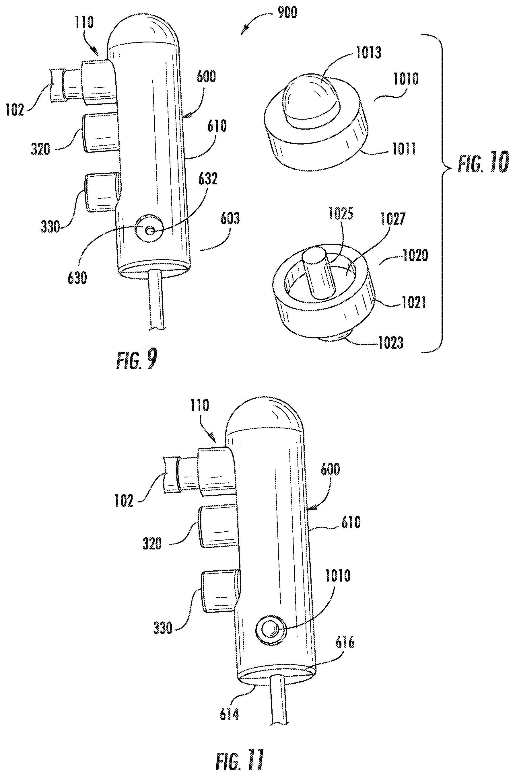
FIG. 9 is an enlarged view of the sliding spindle of FIG. 6 depicting a recess for receiving a pin, in accordance with aspects of the present disclosure;
FIG. 10 is a perspective view of a pair of pins inserted into recesses of the sliding spindle of FIG. 6, in accordance with aspects of the present disclosure;
FIG. 11 is an enlarged view of the sliding spindle of FIG. 6 depicting the pair of pins of FIG. 10 inserted thereto, in accordance with aspects of the present disclosure;
FIG. 12 is a perspective view of a locking spindle, in accordance with aspects of the present disclosure;
FIG. 13 is an enlarged view of the locking spindle of FIG. 12 assembled onto the sliding spindle of FIG. 6, in accordance with aspects of the present disclosure;
FIG. 14A is a perspective view of a first embodiment of a control ring, in accordance with aspects of the present disclosure;
FIG. 14B is a perspective view of a second embodiment of a control ring, in accordance with aspects of the present disclosure;
FIG. 15A is a cross-sectional view of the control ring of FIG. 14A assembled onto the locking spindle of FIG. 12, where the control ring is in a first or deployed position, in accordance with aspects of the present disclosure;
FIG. 15B is a cross-sectional view of the control ring of FIG. 14A assembled onto the locking spindle of FIG. 12, where the control ring is in a second or retracted position, in accordance with aspects of the present disclosure;
FIG. 16A is a cross-sectional view of the control ring of FIG. 14A assembled onto the locking spindle of FIG. 12, where the control ring is in the second position, in accordance with aspects of the present disclosure;
FIG. 16B is a cross-sectional view of the control ring of FIG. 14A assembled onto the locking spindle of FIG. 12, where the control ring is in the first position, in accordance with aspects of the present disclosure;
FIG. 17 is an enlarged view of the control ring assembled onto the locking spindle, the locking spindle assembled onto the sliding spindle, and the sliding spindle assembled onto the microwave transmission and radiation component, and depicting the inflow and outflow ports, in accordance with aspects of the present disclosure;
FIG. 18 is a perspective view of a nose cone, in accordance with aspects of the present disclosure;
FIG. 19 is a perspective view of the nose cone of FIG. 18 assembled onto the control ring of FIG. 14A, in accordance with aspects of the present disclosure;
FIG. 20 is a cross-sectional view of a portion of the nose cone, the nose cone connected to a retaining ring of the locking spindle to secure the nose cone to the locking spindle, in accordance with aspects of the present disclosure;
FIG. 21 is an enlarged view of the nose cone of FIG. 18 illustrating a hinge component, in accordance with aspects of the present disclosure;
FIG. 22 is a perspective view of a surgical system including a microwave catheter and an access channel device assembled in a manner described with reference to FIGS. 1-20, in accordance with aspects of the present disclosure;
FIG. 23A is a perspective view of a cannula, in accordance with aspects of the present disclosure;
FIG. 23B is a perspective view of a trocar, in accordance with aspects of the present disclosure;
FIG. 23C is a perspective view of the trocar of FIG. 23B being inserted within the cannula of FIG. 23A, in accordance with aspects of the present disclosure;
FIG. 23D is a perspective view of the trocar of FIG. 23B fully inserted within the cannula of FIG. 23A, in accordance with aspects of the present disclosure; and
FIG. 24 is a perspective view of the cannula/trocar assembly of FIG. 23D mounted onto the nose cone of FIG. 18 and the microwave radiation section of FIG. 1, in accordance with aspects of the present disclosure.
DETAILED DESCRIPTION
The present disclosure is directed to a microwave catheter connected to an access channel device at a 90-degree angle or in a substantially perpendicular configuration. The 90-degree transition geometry is enabled by the use of a 90-degree transition head, as well as a multi-lumen overmolded fluid hub having an inflow port and an outflow port that may be substantially parallel to each other. The 90-degree connection or 90-degree interlocking geometry between the microwave catheter and the access channel device reduces the load or pressure applied to the surgeon's hands and arms when manipulating such devices. Additionally, the 90-degree connection or 90-degree interlocking geometry between the microwave catheter and the access channel device enables quick separation of the cannula from the trocar so that the access channel device can be easily placed at a target location. Moreover, the 90-degree connection or 90-degree interlocking geometry between the microwave catheter and the access channel device enables needle-like placement of an elongated non-rigid microwave radiation catheter into targeted tissue for thermal ablation during open, laparoscopic or transcutaneous procedures without a guide wire or pre-established access path.
Embodiments of the microwave ablation systems and components are described with reference to the accompanying drawings. Like reference numerals may refer to similar or identical elements throughout the description of the figures. As shown in the drawings and as used in this description, the term "proximal" refers to that portion of the apparatus, or component of the apparatus, closer to the user and the term "distal" refers to that portion of the apparatus, or a component of the apparatus, farther from the user.
This description may use the phrases "in an embodiment," "in embodiments," "in some embodiments," or "in other embodiments," which may each refer to one or more of the same or different embodiments in accordance with the present disclosure.
As it is used in this description, "microwave" generally refers to electromagnetic waves in the frequency range of 300 megahertz (MHz) (3.times.10.sup.8 cycles/second) to 300 gigahertz (GHz) (3.times.10.sup.11 cycles/second). As it is used in this description, "ablation procedure" generally refers to any ablation procedure, such as, for example, microwave ablation, radiofrequency (RF) ablation, or microwave or RF ablation-assisted resection. As it is used in this description, "transmission line" generally refers to any transmission medium that can be used for the propagation of signals from one point to another. As it is used in this description, "fluid" generally refers to a liquid, a gas, or both. The term "coolant" may be used interchangeable with the term "fluid."
Reference will now be made in detail to embodiments of the present disclosure. While certain exemplary embodiments of the present disclosure will be described, it will be understood that it is not intended to limit the embodiments of the present disclosure to those described embodiments. To the contrary, reference to embodiments of the present disclosure is intended to cover alternatives, modifications, and equivalents as may be included within the spirit and scope of the embodiments of the present disclosure as defined by the appended claims.
Referring initially to FIG. 1, the microwave transmission and radiation component 100 includes a microwave transmission cable assembly 102 connected to a microwave antenna assembly 108 via a transition head 110. The microwave antenna assembly 108 includes a feedline 106 and a radiating section 106a located at a distal portion thereof and in electrical communication with the coaxial feed line 106. The transition head 110 may be referred to as a 90-degree transition head 110. The microwave transmission cable assembly 102 has a proximal end 101 and a distal end 103. The proximal end 101 may have a spring-biased coupling element 104. The spring-biased coupling element 104 may be coupled to a housing 2212 (FIG. 22) for connection to a microwave generator. The microwave antenna assembly 108 has a proximal end 105 and a distal end 107. In some embodiments, the microwave transmission cable assembly 102 has a first diameter and the coaxial feed line 106 has a second diameter, the first diameter being greater than the second diameter. The transition head 110 allows for a 90-degree connection to be established between the microwave transmission cable assembly 102 and the coaxial feed line 106 of the microwave antenna assembly 108, as described in detail below with reference to FIG. 2.
As shown in FIG. 2, the transition head 110 is formed by a first section 111 and a second section 113. The first and second sections 111, 113 are perpendicular to each other and form a 90-degree angle therebetween. The first and second sections 111, 113 form a 90-degree interlocking geometry. The first section 111 is coupled to the proximal end 105 of the coaxial feed line 106. The second section 113 is coupled to the distal end 103 of the microwave transmission cable assembly 102 via a tubular member 118. A 90-degree coaxial cable connector (not shown but incorporated into the transition head 110) enables electrical connection between the microwave transmission cable assembly 102 and the coaxial feed line 106. The first section 111 further includes an o-ring 115 circumferentially positioned about a portion thereof. The o-ring 115 does not contact the second section 113, but ensures a water tight seal when the transition head 110 is integrated with a multi-lumen hub as described below with respect to FIG. 3.
As shown in FIG. 3, the multi-lumen hub 300 includes a body portion or hub 310. The body portion 310 has a proximal end 301 and a distal end 303. The body portion 310 defines an upper body portion 311 and a lower body portion 313. The upper body portion 311 defines a chamber 312 and the lower body portion 313 houses a cannula 314. The chamber 312 is in fluid communication with the cannula 314. The cannula 314 defines a longitudinal axis "X" therethrough.
The cannula 314 may be formed of a rigid or a flexible material. In certain embodiments a combination of rigid (e.g., steel or ceramic) and flexible (e.g., polymeric materials) may be employed. Further, the cannula 314 may be pre-curved or shaped to reach a desired location within the physiology of a patient. Still further, the cannula 314 may employ one or more pairs of steering wires, enabling the cannula to be articulated in one or more directions. The use of a flexible material enables the advancement and navigation of the cannula 314 for the proper placement of the radiating section 106a housed therein, as will be described herein below.
The multi-lumen hub 300 includes an inflow port 320 and an outflow port 330. The inflow port 320 may also be referred to as a fluid intake port and the outflow port 330 may also be referred to as a fluid return port. The inflow port 320 defines an inflow lumen 322 therethrough and the outflow port 330 defines an outflow lumen 332 therethrough. The inflow and outflow ports 320, 330 provide respective ingress and egress of a fluid or coolant to and from the body portion 310 of the multi-lumen hub 300 for cooling the coaxial feed line 106 and radiating section 106a of the microwave transmission and radiation component 100 of FIG. 1.
The inflow port 320 is substantially parallel to the outflow port 330. Thus, the inflow lumen 322 of the inflow port 320 is also substantially in parallel to the outflow lumen 332 of the outflow port 330. The inflow and outflow ports 320, 330 may be substantially perpendicular to the longitudinal axis "X" defined by the cannula 314. The inflow and outflow ports 320, 330 have substantially circular openings. However, one skilled in the art may contemplate various geometrical openings for inflow and outflow ports 320, 330. The inflow port 320 cooperates with the upper body portion 311 of the body portion 310, whereas the outflow port 330 cooperates with the lower body section 313 of the body portion 310. The inflow port 320 is in fluid communication with the chamber 312, whereas the outflow port 330 is in fluid communication with the cannula 314. The cannula 314 extends beyond a distal end of the lower body portion 313 of the body portion 310. The diameter of the inflow and outflow lumens 322, 332 are greater than the diameter of the cannula 314. The diameter of the chamber 312 is greater than the diameter of the inflow and outflow ports 320, 330.
Referring to FIG. 4, the assembled view 400 of the microwave transmission and radiation component 100 and the multi-lumen overmolded fluid hub 300 is shown. The microwave transmission and radiation component 100 is inserted into the multi-lumen hub 300. Cannula 314 receives the coaxial feed line 106 and radiating section 106a of the microwave transmission and radiation component 100. The o-ring 115 (FIG. 2) is positioned in chamber 312 (FIG. 3) to secure the second section 113 of the transition head 110 adjacent the proximal end 301 of the multi-lumen hub 300 at a region 410.
The cannula 314 and the multi-lumen hub 300 define a longitudinal axis "X" therethrough. The microwave transmission cable assembly 102 defines a longitudinal axis "Y" extending therethrough. The longitudinal axis "X" is substantially perpendicular to the longitudinal axis "Y." Thus, the multi-lumen hub 300 is assembled at a 90-degree angle with respect to the microwave transmission cable assembly 102. As a result, the 90-degree interlocking geometry of the transition head 110 enables a 90-degree placement or positioning of the multi-lumen hub 300 with respect to the microwave transmission cable assembly 102.
Referring to FIG. 5, the first section 111 of the transition head 110 is inserted into or received within the chamber 312 of the body portion 310 of the multi-lumen hub 300. The second section 113 of the transition head 110 is secured adjacent the proximal end 301 of the multi-lumen hub 300 at a region 410. The second section 113 of the transition head 110 seals off the chamber 312 via the o-ring 115. The o-ring 115 sits at the proximal end 301 of the upper body portion 311 and within the chamber 312. The o-ring 115 circumferentially engages an inner surface of the chamber 312 to form a tight seal thereof.
Additionally, the cross-sectional view 500 illustrates a connecting member 120 for coupling the end 118 of the microwave transmission cable assembly 102 to the coaxial feed line 106. The connecting member 120 is fully positioned within the second section 113 of the transition head 110.
In FIG. 5, the inflow port 320 is substantially parallel to the outflow port 330. The inflow and outflow ports 320, 330 may be substantially in parallel to the microwave transmission cable assembly 102. Thus, the microwave transmission cable assembly 102, the inflow port 320, and the outflow port 330 are all substantially perpendicular to the multi-lumen hub 300 and with the coaxial feed line 106. The coaxial feed line 106 extends the length of the cannula 314. The cannula 314 is in fluid communication with both the inflow port 320 and the outflow port 330 such that a coolant flows along the coaxial feed line 106 and around the radiating section 106a formed on a distal portion of the coaxial feed line 106.
Referring to FIG. 6, an actuator is shown, such as for example, a sliding spindle 600 that includes a body portion 610 having a proximal portion 601 and a distal portion 603. The proximal portion 601 defines, for example, a dome-shaped portion 612. The body portion 610 further defines an opening 620, as well as a pair of recesses 630. The recesses 630 are positioned on opposed sides of the distal portion 603 of the body portion 610. The recesses 630 are offset from the opening 620. The offset may be a 90-degree offset. Each of the pair of recesses 630 includes an aperture 632. The body portion 610 is defined by a first body section 614 and a second body section 616 which are joined to form the body portion 610. The distal portion 603 of the sliding spindle 600 further defines an aperture 618. The aperture 618 is configured to allow the coaxial cannula 314 to pass therethrough, as discussed below with reference to FIG. 7.
The elongated body portion 610 of the sliding spindle 600 is assembled over the multi-lumen hub 300 and the transition head 110. The second section 113 of the transition head 110, the inflow port 320, and the outflow port 330 extend through the opening 620 (FIG. 6) of the body portion 610. Both the first section 111 and the second section 113 of the transition head 110 are at least partially enclosed within the sliding spindle 600. The dome-shaped portion 612 of the body portion 610 of the spindle 600 is secured adjacent the second section 113 of the transition head 110. The cannula 314 of the multi-lumen hub 300 extends through the aperture 618 of the sliding spindle 600. The cannula 314 defines a longitudinal axis "X" extending through the multi-lumen hub 300 and the sliding spindle 600.
Referring to FIG. 8, the assembled view 800 of the microwave transmission and radiation component 100 and the multi-lumen overmolded fluid hub 300 and the sliding spindle 600 is shown. The microwave transmission and radiation component 100 is inserted into the multi-lumen hub 300 such that the coaxial feed line 106 and radiating section 106a are received within the cannula 314. Then the sliding spindle 600 is assembled over the multi-lumen hub 300. The cannula 314 and the multi-lumen hub 300, and the sliding spindle 600 define a longitudinal axis "X" therethrough. The microwave transmission cable assembly 102 defines a longitudinal axis "Y" extending therethrough. The longitudinal axis "X" is substantially perpendicular to the longitudinal axis "Y." Thus, the sliding spindle 600 and the multi-lumen hub 300 are assembled at a 90-degree angle with respect to the microwave transmission cable assembly 102.
In FIG. 9, the recess 630 is a circular recess defined at the distal portion 603 of the body portion 610 of the sliding spindle 600. In the embodiment depicted in FIG. 9, a similar recess 630 on the other side of the sliding spindle 600 is present (not shown). Therefore, a pair of recesses 630 are defined on diametrically opposed surfaces of the distal portion 603 of the body portion 610. The recesses 630 are each configured to receive a pair of pins 1010, 1020 shown in FIG. 10. The first pin 1010 includes a first section 1011 and a second section 1013. The second pin 1020 is similar to the first pin 1010, but is shown in an inverted configuration with respect to the first pin 1010. The second pin 1020 includes a first section 1021 and a second section 1023. The second pin 1020 also includes a rod 1025 extending away from the first section 1021. The first section 1021 defines an annular recess 1027 surrounding the rod 1025. The rod 1025 is configured to be received within an aperture 632 of the recess 630 to secure the second pin 1020 to the recess 630 of the sliding spindle 600. As can be appreciated, a spring (not shown) may be received in the annular recess 1027 to push the pins 1010 and 1020 away from the body portion 610 of the sliding spindle 600, when the pins 1010, 1020 are received within the recesses 630, as shown in FIG. 11, and in accordance with embodiments described below.
Referring to FIG. 12, the locking spindle 1200 includes a body portion 1205 having a proximal end 1201 and a distal end 1203. The distal end 1203 includes a retaining ring 1210. The body portion 1205 includes an opening 1250 for receiving the inflow port 320, the outflow port 330, and the microwave transmission cable assembly 102 (FIG. 13). The body portion 1205 further includes a pair of longitudinal slots 1220. As shown in FIG. 12, the longitudinal slots 1220 separate a first circular end 1222 from a second circular end 1224. The pair of longitudinal slots 1220 and their respective first and second circular ends 1222, 1224 are configured to receive the pins 1010, 1020 (FIG. 10) as will described in further detail below. The distal end 1203 may further define an aperture 1215 for receiving the cannula 314 (FIG. 13) into which the feed line 106 and radiating section 106a have been inserted. The longitudinal slots 1220 may also be referred to as camming surfaces. The first and second circular ends 1222, 1224 may be of equal size.
The body portion 1205 also includes an opening or cut-out 1230. The opening 1230 extends a length of the body portion 1205 such that the inflow port 320, the outflow port 330, and the distal end 103 of the microwave transmission cable assembly 102 are accommodated therein (FIG. 16B). The opening 1230 may be offset from the pair of longitudinal slots 1220. The offset may be a 90-degree offset.
Referring to FIG. 13, the assembled view 1300 illustrates the sliding spindle 600 assembled over the multi-lumen hub 300 received in the locking spindle 1200 such that the pins 1010, 1020 of the sliding spindle 600 engage their respective longitudinal slots 1220 of the locking spindle 1200. The pins 1010, 1020 slide along their respective longitudinal slots 1220 such that the pins 1010, 1020 travel from or between the first circular end 1222 and the second circular end 1224. A biasing means, such as a spring (not shown) forces the pins 1010, 1020, away from the body portion 610 of the sliding spindle 600 and into engagement with the circular end 1222, as shown in FIG. 13.
Referring to FIG. 14A, an actuator, such as a control ring 1400A is shown and includes a body portion 1410 having a proximal end 1401 and a distal end 1403. The proximal end 1401 has a pair of projections 1430 extending outward from the body portion 1410. The pair of projections 1430 defines a first arm section 1432 and a second arm section 1434. The first arm section 1432 is substantially perpendicular to the body portion 1410 or the longitudinal axis "Z" defined through the body portion 1410. The second arm portion 1434 is, for example, a curved portion. The pair of projections 1430 forms a handle member for manual manipulation. The body portion 1410 also defines an opening or cut-out 1420 for receiving or accommodating therein the inflow port 320, the outflow port 330, and the microwave transmission cable assembly 102 (FIG. 17). The control ring 1400A further defines a channel or through passage 1450 therethrough. The interior surface of the control ring 1400A may include one or more stops 1460.
Referring to FIG. 14B, the control ring 1400B includes a body portion 1410' having a proximal end 1401' and a distal end 1403'. The proximal end 1401' has a first pair of projections 1430' extending outward from the body portion 1410' and a second pair of projections 1440' extending outward from the body portion 1410'. The first and second pair of projections 1430', 1440' may be substantially perpendicular to the body portion 1410' or the longitudinal axis "Z" defined through the body portion 1410'. The first and second pair of projections 1430', 1440' may form a handle member for manual manipulation. The body portion 1410' also defines an opening or cut-out 1420' for receiving or accommodating therein the inflow port 320, the outflow port 330, and the microwave transmission cable assembly 102 (FIG. 17). The control ring 1400B further defines a channel 1450' therethrough. The interior surface of the control ring 1400B may include one or more stops 1460'.
Both the sliding spindle 600 and the control arm 1400A are described herein as an actuator. One of skill in the art will recognize that in accordance with the present disclosure these two actuators may operate individually or in concert, and they may act on different components of the assemblies described herein.
The deployment of the cannula 314 housing the coaxial feed line 106 and radiating section 106a will now be described with reference to FIGS. 15A and 15B. FIG. 15A is a cross-sectional view 1500A of the control ring 1400A of FIG. 14A assembled onto the locking spindle 1200 of FIG. 12 and sliding spindle 600 of FIG. 11, where the cannula 314 is in a deployed position, in accordance with aspects of the present disclosure.
FIG. 15A, the control ring 1400A is assembled onto or mounted on the locking spindle 1200 such that the pins 1010, 1020 of the sliding spindle 600 travel along the slotted openings 1220 of locking spindle 1200. The opening 1420 (FIG. 14A) may extend a substantial length of the body portion 1410 of the control ring 1400A. In the deployed position, the sliding spindle 600 rests in the lower portion of the area 1550 defined by the locking spindle 1200, and the pins 1010, 1020 rest within the second circular ends 1224 proximate the distal end 1403 of the control ring 1400A. The second sections 1013, 1023 (FIG. 10) of the pins 1010, 1020, respectively, are protruding members such that when the pins are depressed into the recesses 630 of the sliding spindle 600, they permit the movement of the sliding spindle 600 relative to the locking spindle 1200 via slotted opening 1220 and prevent the removal of the sliding spindle 600 from the locking spindle 1200.
FIG. 15B is a cross-sectional view 1500B of the control ring 1400A of FIG. 14A assembled onto the locking spindle 1200 of FIG. 12 and sliding spindle 600 of FIG. 11, where the cannula 314 is in a retracted position, in accordance with aspects of the present disclosure.
In the retracted position, the sliding spindle 600 rests in the upper portion of the area 1550 defined by the locking spindle 1200. In both these configurations, the transition head 110 remains secured to the multi-lumen hub 300 within the sliding spindle 600, and the cannula 314 moves relative to the locking spindle 1200. In the retracted position, the pins 1010, 1020 rest within the first circular ends 1222 or at the proximal end 1401 of the control ring 1400A.
Additionally, since the control ring 1400A is mounted onto the locking spindle 1200, the control ring 1400A also moves relative to the sliding spindle 600. Thus, when a holding force "A" is applied to the sliding spindle, and an actuating force "C" is applied to the pair of projections 1430, of the control ring 1400A such that the sliding spindle 600 does not move, the control ring 1400A moves in a direction "B." This movement results in the change depicted by comparison of FIG. 15B, retracted position, to FIG. 15A, deployed position. In such a transition, the pins 1010, 1020 travel along their respective longitudinal slots 1220 between the first circular ends 1222 and the second circular ends 1224. The sliding spindle 600 engages the inner surface 1525 of the locking spindle 1200 within the area 1550. Thus, the locking spindle 1200 selectively locks the sliding spindle 600 between an extended position and a retracted position. As a result, the cannula 314 may be extended and retracted based on relative movement of the sliding spindle 600 and the control ring 1400A and the locking spindle 1200.
FIG. 16A shows an alternate view of the control ring 1400A of FIG. 14A assembled onto the locking spindle 1200 of FIG. 12, where the cannula 314 and sliding spindle 600 are in the retracted position. Similarly, FIG. 16B shows an alternate view of the control ring 1400A of FIG. 14A assembled onto the locking spindle 1200 of FIG. 12, where cannula 314 is placed in the deployed position. FIGS. 16A and 16B show the inflow port 320, the outflow port 330, and the microwave transmission cable assembly 102 extending through the opening 1230 (FIG. 12) of the locking spindle 1200 and the opening 1420 (FIG. 14A) of the control ring 1400A. In addition, the inflow port 320, the outflow port 330, and the distal end 103 of the microwave transmission cable assembly 102 move within the area defined by the opening 1230 of the locking spindle 1200 and the opening 1420 of the control ring 1400A (when transitioning between extended and retracted positions).
As noted above with reference to FIGS. 16A and 16B, the inflow port 320, the outflow port 330, and the distal end 103 of the microwave transmission cable assembly 102 move within the area defined by the opening 1230 (FIG. 12) of the locking spindle 1200 and the opening 1420 of the control ring 1400A (when transitioning between extended and retracted positions). The openings 1230 and 1420 overlap each other. FIG. 17 also provides an alternate perspective view of the sliding spindle 600, within the locking spindle 1200, and the control ring 1400A.
FIG. 18 depicts a nose cone 1800 for connection to locking spindle 1200. The nose cone 1800 includes a body portion 1810 defining an upper body section 1811 and a lower body section 1813. The upper body section 1811 includes a cut-out section 1815. The body portion 1810 has a distal portion 1820 formed at the lower body section 1813. The distal portion 1820 has an aperture 1830.
Referring to FIG. 19, the upper body portion 1811 is configured to receive the distal end 1203 of the locking spindle 1200 (FIG. 12) and the distal end 1403 (FIG. 17) of the control ring 1400A. The cut-out section 1815 of the upper body portion 1811 is configured to surround the outflow port 330. The cannula 314 extends through the aperture 1830 of the distal portion 1820 of the nose cone 1800. Thus, the aperture 1830 is adapted and dimensioned to receive the cannula 314.
As shown in FIG. 20, the nose cone 1800 includes a recess 2010 on an inner surface 2012 thereof for receiving a retaining ring 1210 of the locking spindle 1200. The recess 2010 is an annular recess defined along the inner surface 2012 of the nose cone 1800. The retaining ring 1210 interacts with the recess 2010 to secure the nose cone 1800 to the locking spindle 1200.
In FIG. 21, the locking mechanism 2110 is shown positioned on a distal end 2114 of a flat surface 2112 of the distal portion 1820 of the nose cone 1800. The locking mechanism 2110 is configured to mate with a trocar/cannula assembly described below with reference to FIGS. 23A-23D.
FIG. 22 depicts a fully assembled microwave ablation assembly 2200 including a housing 2212 covering spring-biased coupling element 104 for connection to a microwave generator. The microwave transmission cable assembly 102 may include covering having a slot 2214 through which a first fluid flow channel 2216 and a second fluid flow channel 2218 exit. The first fluid flow channel 2216 is connected to the inflow port 320 and the second fluid flow channel is connected to the outflow port 330. Though not shown, the microwave generator may include a fluid source and enable connection of the fluid source through the housing 2212.
Insertion and deployment of the microwave ablation assembly 2200 is described with reference to FIGS. 23A-24. FIG. 23A depicts a rigid cannula 2310 including a housing 2316 connected to a shaft 2312 having a distal portion 2314. The housing 2316 includes a slot 2318 for receiving a locking mechanism 2328 or 2110. FIG. 23B shows the trocar 2320, which includes a retaining member 2326 connected to a shaft portion 2322 having a distal tip 2324. The retaining member 2326 includes a locking mechanism 2328. Referring now to FIGS. 23C and 23D, the locking mechanism 2328 of the trocar 2320 mates with the slot 2318 of the housing 2316 of the cannula 2310. The locking mechanism 2328 secures the trocar 2320 to the cannula 2310. The trocar 2320 is thus releasably coupled to the cannula 2310. The distal tip 2324 may be a relatively pointed tip to pierce through tissue.
Typically a clinician, when performing for example a liver ablation procedure, will acquire a series of images to identify the location of a tumor or lesion for ablation. Once identified, the clinician will seek to place the cannula 2310 and trocar 2320 assembly as shown in FIG. 23D proximate that tumor or lesion. This placement may be performed through a variety of techniques including under fluoroscopy, ultrasound, MRI, and CT imaging techniques either alone or in combination with one or more navigation techniques, such as electromagnetic navigation. Once the cannula 2310 and trocar 2320 assembly is positioned in a desired location within a patient proximate the tumor or lesion, the trocar 2320 may be removed. The cannula 2310 remains in place ready to receive the microwave ablation assembly 2200 or where appropriate the performance of one or more pre-treatment biopsies.
The microwave ablation assembly 2200 may then be placed within the cannula 2310 at the desired location proximate the tumor or lesion and secured to the cannula 2310 via locking mechanism 2110 on the nose cone 1800 and slot 2310 on the housing 2316 of the cannula 2310. However, to protect the feed line 106 and radiating section 106a, within the cannula 314, the cannula 314 is not yet deployed from the cannula 2310. To deploy the cannula 314, within which is housed the feed line 106 and, more specifically, the radiating section 106a, the control ring 1400A and locking spindle 1200 must be compressed relative to the sliding spindle 600. By the relative movement of the locking spindle over the sliding spindle 600 (which is preferably held stationary), the cannula 2310 is retracted relative to the cannula 314, exposing the cannula 314, and specifically, the radiating section 106a housed therein.
FIG. 24 shows the cannula 314 extended beyond the distal end of the cannula 2310. In this position, the cannula 2310 has been retracted, thus exposing cannula 314 and the radiating section 106a of the microwave ablation assembly 2200. The cannula 314 has been exposed by application of pressure on the control ring 1400a (FIG. 14A) which overcomes the retaining force imparted by the pins 1020, 1030 (FIG. 10), thus allowing control ring 1400a and locking spindle 1200 (FIG. 12) to move relative to the sliding spindle 600 (FIG. 6). In this position, the microwave assembly 2210 is in a position to perform an ablation.
As described herein, in a preferred embodiment of the present disclosure, the sliding spindle 600, the multi-lumen housing 300, and the microwave transmission and radiation component 100 remain fixed in space (or remain stationary) when the cannula 314, and more particularly the radiating section 106a is deployed to a surgical site or target. The locking spindle 1200, the control ring 1400A, and the nose cone 1800 are drawn in a direction away from the surgical site when the radiating section 106a is deployed to the surgical site or target.
The present disclosure enables placement of a cannula 314, which may be flexible, including radiating section 106a, from a non-radiofrequency transparent access lumen such as cannula 2310 in a variety of interventional procedure types. These interventional procedures include transcutaneous placement (analogous to rigid biopsy kit), open procedure (rigid-needle-like), laparoscopic procedure (hand assisted placement). By use of the cannula 2310 and trocar 2320, an access path to a particular treatment site can be considered separately from the energy delivery device constraints. It is further envisioned that the methods and devices described herein can enable vascular access, whereby a cannula 314, being of flexible construction could be placed with steerable guide-wires. Still further, hybrid procedures utilizing a cannula 314 that is partially rigid and partially flexible are also contemplated.
In accordance with another aspect of the present disclosure, access approaches are envisioned where following placement of the cannula 2310 and removal of the trocar 2320, the cannula 314, which may include steerable guide wires or may be inserted through a flexible guide sheath with steerable guide-wire can extend the access path with 4-dimensional freedom.
The systems and methods of the present disclosure enable an improved workflow by separating the clinician's needs during the access channel placement from the clinician's needs associated with energy delivery. By utilizing the cannula 2310 and trocar 2320 separately, from the microwave ablation assembly 2200, the clinician does not have to deal with constraints of the microwave ablation assembly 2200 while placing the cannula 2310. This removal of the concerns of microwave cables, fluid lines, device weight, handle length, etc., greatly improves the clinician's ability to focus on cannula 2310 placement at or near the target site, and further allows for easier imaging of the placement site (e.g., by fluoroscopy or CT imaging). Still further, because the microwave and fluid componentry is not employed during the cannula 2310 insertion steps, through space savings within the device, the trocar 2320 and cannula 2310 may `onboard` additional capabilities such as EM navigation sensors, temperature sensors, device fixation features, and other diagnostic capabilities.
In accordance with the present disclosure, the cannula 2310 may have a smaller diameter gauge or French size) than existing devices for placement of microwave ablation components. Indeed, the cannula 2310 may be one of a series of cannulas which are used to dilate the size of the opening in order to receive the microwave ablation assembly 2200.
Detailed embodiments of devices, systems incorporating such devices, and methods using the same as described herein. However, these detailed embodiments are merely examples of the disclosure, which may be embodied in various forms. Therefore, specific structural and functional details disclosed herein are not to be interpreted as limiting, but merely as a basis for the claims and as a representative basis for allowing one skilled in the art to variously employ the present disclosure in appropriately detailed structure.
While several embodiments of the disclosure have been shown in the drawings, it is not intended that the disclosure be limited thereto, as it is intended that the disclosure be as broad in scope as the art will allow and that the specification be read likewise. Any combination of the above embodiments is also envisioned and is within the scope of the appended claims. Therefore, the above description should not be construed as limiting, but merely as exemplifications of particular embodiments. Those skilled in the art will envision other modifications within the scope of the claims appended hereto.
* * * * *
References
D00000
D00001
D00002
D00003
D00004
D00005
D00006
D00007
D00008
D00009
D00010
D00011
D00012

D00013

D00014

D00015

D00016

D00017

D00018
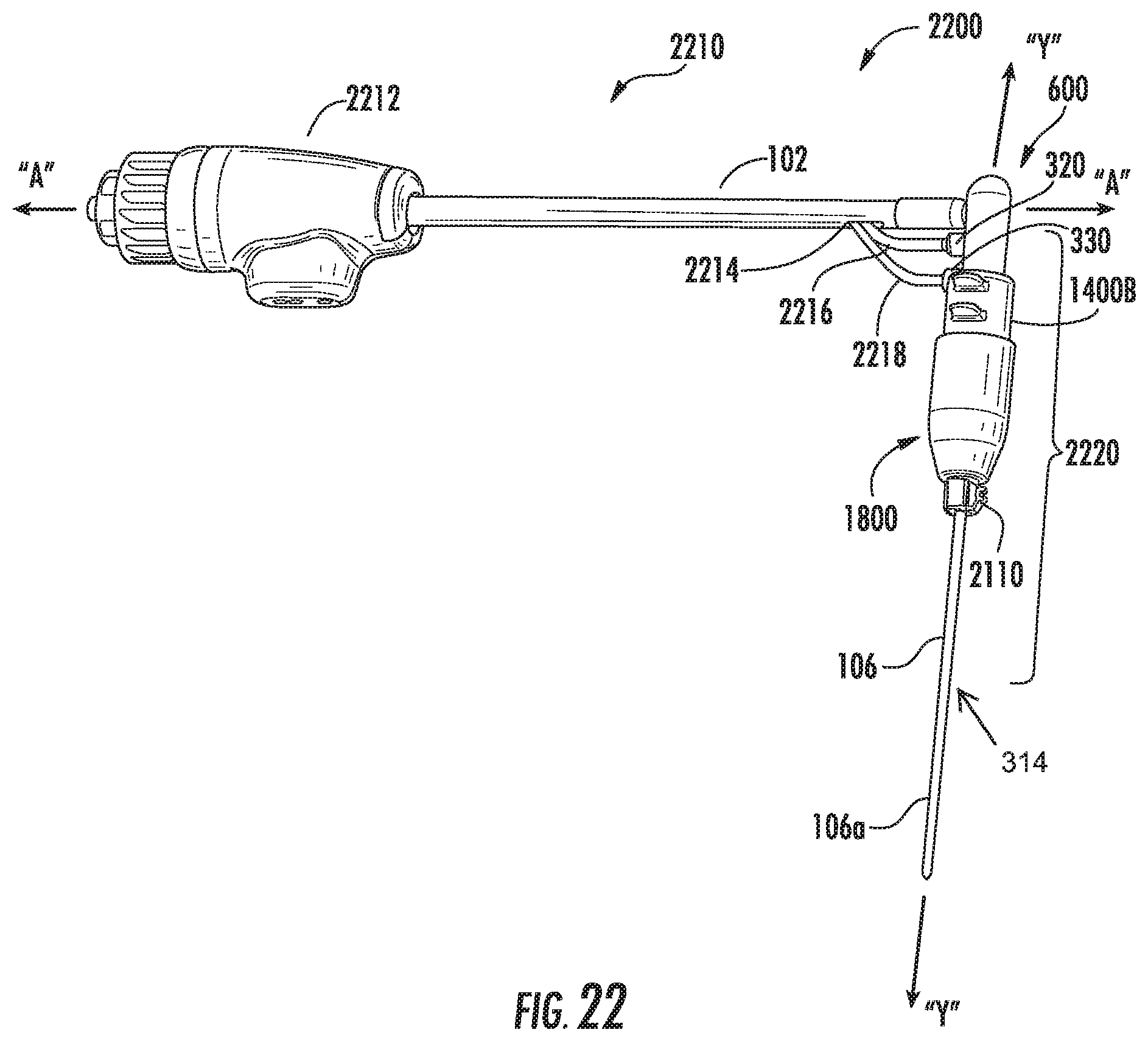
D00019

D00020

XML
uspto.report is an independent third-party trademark research tool that is not affiliated, endorsed, or sponsored by the United States Patent and Trademark Office (USPTO) or any other governmental organization. The information provided by uspto.report is based on publicly available data at the time of writing and is intended for informational purposes only.
While we strive to provide accurate and up-to-date information, we do not guarantee the accuracy, completeness, reliability, or suitability of the information displayed on this site. The use of this site is at your own risk. Any reliance you place on such information is therefore strictly at your own risk.
All official trademark data, including owner information, should be verified by visiting the official USPTO website at www.uspto.gov. This site is not intended to replace professional legal advice and should not be used as a substitute for consulting with a legal professional who is knowledgeable about trademark law.