Nose knife
Haruna , et al. October 27, 2
U.S. patent number 10,813,654 [Application Number 16/341,431] was granted by the patent office on 2020-10-27 for nose knife. This patent grant is currently assigned to MANI, INC.. The grantee listed for this patent is MANI, Inc.. Invention is credited to Shinichi Haruna, Masaaki Matsutani, Masato Suda.


| United States Patent | 10,813,654 |
| Haruna , et al. | October 27, 2020 |
Nose knife
Abstract
A nose knife with good usability and little interference with tools such as an endoscope in nasal cavity surgery is provided, and includes a handle, a shank, and a blade. The shank includes a straight part connected straight to the handle along the same axis, and a curved part integrally connected to the front end of the straight part. The blade is provided at the front end of the curved part. A tip of the blade is angled 65 degrees to 75 degrees inclusive relative to the axis of the straight part.
| Inventors: | Haruna; Shinichi (Shimotsuga-gun, JP), Suda; Masato (Utsunomiya, JP), Matsutani; Masaaki (Utsunomiya, JP) | ||||||||||
|---|---|---|---|---|---|---|---|---|---|---|---|
| Applicant: |
|
||||||||||
| Assignee: | MANI, INC. (Utsunomiya-shi,
Tochigi, JP) |
||||||||||
| Family ID: | 1000005139589 | ||||||||||
| Appl. No.: | 16/341,431 | ||||||||||
| Filed: | October 11, 2017 | ||||||||||
| PCT Filed: | October 11, 2017 | ||||||||||
| PCT No.: | PCT/JP2017/036786 | ||||||||||
| 371(c)(1),(2),(4) Date: | April 11, 2019 | ||||||||||
| PCT Pub. No.: | WO2018/070409 | ||||||||||
| PCT Pub. Date: | April 19, 2018 |
Prior Publication Data
| Document Identifier | Publication Date | |
|---|---|---|
| US 20190262017 A1 | Aug 29, 2019 | |
Foreign Application Priority Data
| Oct 13, 2016 [JP] | 2016-201636 | |||
| Current U.S. Class: | 1/1 |
| Current CPC Class: | A61B 17/3211 (20130101); A61B 17/32 (20130101); A61B 17/24 (20130101) |
| Current International Class: | A61B 17/24 (20060101); A61B 17/3211 (20060101); A61B 17/32 (20060101) |
References Cited [Referenced By]
U.S. Patent Documents
| 1339691 | May 1920 | Diamant |
| 1628275 | May 1927 | Robinson |
| 3256874 | June 1966 | De Marco |
| 4572180 | February 1986 | Deenadayalu |
| 5152744 | October 1992 | Krause |
| 5203865 | April 1993 | Siepser |
| 5217476 | June 1993 | Wishinsky |
| 5234452 | August 1993 | Wang-On |
| 5282796 | February 1994 | Knoepfler |
| 5282816 | February 1994 | Miller |
| 5320635 | June 1994 | Smith |
| 5336235 | August 1994 | Myers |
| 5522829 | June 1996 | Michalos |
| 5876416 | March 1999 | Hill |
| 5893861 | April 1999 | Yumoto |
| D423669 | April 2000 | Huttner |
| D428489 | July 2000 | Huttner |
| 7055248 | June 2006 | Cote |
| 7331956 | February 2008 | Hovda |
| 10238417 | March 2019 | Carpenter |
| 2001/0029386 | October 2001 | Matsutani |
| 2003/0074014 | April 2003 | Castaneda |
| 2004/0024401 | February 2004 | Garito |
| 2004/0089159 | May 2004 | Matsutani |
| 2004/0133224 | July 2004 | Scheller |
| 2004/0153108 | August 2004 | Matsutani |
| 2004/0243157 | December 2004 | Connor |
| 2004/0260276 | December 2004 | Rudko |
| 2006/0029906 | February 2006 | Hill |
| 2006/0058824 | March 2006 | Kozlowski |
| 2006/0263745 | November 2006 | Lasner |
| 2006/0276816 | December 2006 | Eckman |
| 2007/0073282 | March 2007 | McGaffigan |
| 2007/0129751 | June 2007 | Muni |
| 2008/0065222 | March 2008 | Hamada |
| 2008/0269791 | October 2008 | Hoenes |
| 2013/0066164 | March 2013 | Nakamura |
| 2015/0018714 | January 2015 | Chen |
| 2016/0030368 | February 2016 | Atkins, Jr. |
| 2017/0014152 | January 2017 | Noui |
| 2017/0164975 | June 2017 | Wu |
| S60128611 | Aug 1985 | JP | |||
| H04067414 | Jun 1992 | JP | |||
| 2004147914 | May 2004 | JP | |||
| 2006006692 | Jan 2006 | JP | |||
| 2009511097 | Mar 2009 | JP | |||
| 2012074084 | Jun 2012 | WO | |||
| 2015132401 | Sep 2015 | WO | |||
Other References
|
Review_of_Computer-Aided_Sinus_Surgery, Byung-Ju Yi, Hyun-Soo Yoon, Hanyang Medical Rev 2016;36:248-253. cited by examiner . International Search Report (ISR) for Application No. PCT/JP2017/036786 dated Nov. 7, 2017. cited by applicant . Translation of the ISR for Application No. PCT/JP2017/036786 dated Nov. 7, 2017. cited by applicant . Written Opinion of the International Search Authority for Application No. PCT/JP2017/036786 dated Nov. 7, 2017. cited by applicant. |
Primary Examiner: Michalski; Sean M
Attorney, Agent or Firm: Isshiki International Law Office Farrar, Esq.; Joseph P.
Claims
The invention claimed is:
1. A nose knife comprising: a handle having a non-slip surface and a circular cross-section; a shank including a single straight part, extending the length of the shank, connected to the handle and aligned with a main longitudinal axis of the handle, and a curved part integrally connected to a front end of the straight part; and a blade with a cutting edge, provided at a front end of the curved part of the shank, wherein a tip of the blade is angled 65 degrees to 75 degrees inclusive relative to a central axis of the straight part of the shank, wherein the nose knife is configured to be rotated around the longitudinal axis of the handle so as to make an incision.
2. The nose knife of claim 1, wherein a length of the straight part is 50 mm to 60 mm inclusive, and the tip of the blade is located 10 mm to 20 mm inclusive from the central axis of the straight part in a perpendicular direction to the central axis.
3. The nose knife of claim 1, wherein a cross-sectional shape of the straight part is a circle having a diameter of 1.5 mm to 2.5 mm inclusive.
4. The nose knife of claim 2, wherein a cross-sectional shape of the straight part is a circle having a diameter of 1.5 mm to 2.5 mm inclusive.
Description
CROSS REFERENCE TO RELATED APPLICATIONS
The present application is a national phase entry under 35 U.S.C. .sctn. 371 of International Application No. PCT/JP2017/036786, filed Oct. 11, 2017, which claims priority from Japanese Application No. JP2016-201636, filed Oct. 13, 2016, the entire disclosures of which are hereby incorporated by reference herein.
TECHNICAL FIELD
The present invention relates to a nose knife used in nasal cavity surgery.
BACKGROUND ART
A dedicated nose knife is used in surgery for nasal cavity diseases. FIG. 4 shows diagrams (a) and (b) exemplifying conventionally used nose knives.
A nose knife 100 in FIG. 4(a) includes a linear shank 11 having a cross-sectional circular shape, a handle 13 applied with a non-slip surface on the base end side of the shank 11, and a blade 12 on the front end side. The diameter of the cross-section of the shank 11 is approximately 3 mm, and length from the base end side of the shank 11 to the blade tip of the blade 12 is approximately 55 mm. The blade 12 is formed protruding slightly from the front end side of the shank 11 and bending from there at nearly a right angle.
A nose knife 101 of FIG. 4(b) includes a shank 11 having a cross-sectional shape of an approximately 2 mm.times.4 mm rectangle. Length from the base end side of the shank 11 to the blade tip of the blade 12 is approximately 43 mm. The shank 11 has a linear shape, and a cross-section decreasing from the middle toward the blade 12. Note that while it is difficult to use the nose knife 101 while rotating it around the axis since the cross-section of the shank 11 is approximately rectangular, it does not slip easily and incisions, etc., may be surely made.
In the case of nasal cavity surgery, the nose knife is inserted in a nostril, and incising and sampling and paring body tissue off, etc., are carried out. At this time, since the nasal cavity is narrow and the interior is difficult to see, an endoscope is often inserted in the nostril at the same time as the nose knife is done in the same way so as to provide treatment in recent years. Here, in the case of the nose knives 100 and 101 as illustrated in FIG. 4(a) and FIG. 4(b), since the shank 11 is thick and has a short length, the handle 13 touches the endoscope, whereby the endoscope and the nose knife interfere with each other. Therefore, a thinner and longer shank of the nose knife is preferred when considering only usability. However, since there are cases where a relatively large force is applied when sampling body tissue, etc., the shank requires a certain amount of strength. That is, the shape of the shank should be determined taking usability and strength into account.
Moreover, an angle between the handle and the blade needs to be given attention as well in order to improve usability of the nose knife. In Patent Document 1 (JP 2004-147914A), for example, curved parts are provided in two places from the handle to the blade tip so as to improve visibility of the knife during surgery, and to make the angle of the knife main body at which it touches a blood vessel be diversely variable.
PRIOR ART DOCUMENTS
Patent Documents
[Patent Document 1] JP 2004-147914A
DISCLOSURE OF THE INVENTION
Problem to be Solved by the Invention
In light of the problem, the present invention aims to provide a nose knife with good usability and little interference with tools such as an endoscope.
Solution to the Problem
The nose knife of the present invention for solving the above problem includes a handle, a shank, and a blade. The shank is characterized in that it includes a straight part connected straight to the handle along the same axis of the handle, and a curved part integrally connected to the front end of the straight part, and the blade is provided at the front end of the curved part, and direction of a blade tip of the blade is 65 degrees to 75 degrees inclusive to the axis line of the straight part.
Moreover, length of the straight part is 50 mm to 60 mm inclusive, and the blade tip of the blade may be located 10 mm to 20 mm inclusive from the central axial line of the straight part in a perpendicular direction to the central axial line. Furthermore, cross-sectional shape of the straight part may be a circle having a diameter of 1.5 mm to 2.5 mm inclusive.
Advantageous Effect of the Invention
According to the nose knife of the present invention, usability of the nose knife in surgery may be improved by providing a curved part and providing a blade at a desired angle.
Furthermore, since the blade tip of the blade is only a desired distance from the straight part, the incision range when the handle is rotated may be enlarged. Moreover, making the cross-sectional shape of the straight part be a circle with a small diameter allows reduction in interference with tools such as an endoscope, thereby improving usability.
BRIEF DESCRIPTION OF THE DRAWINGS
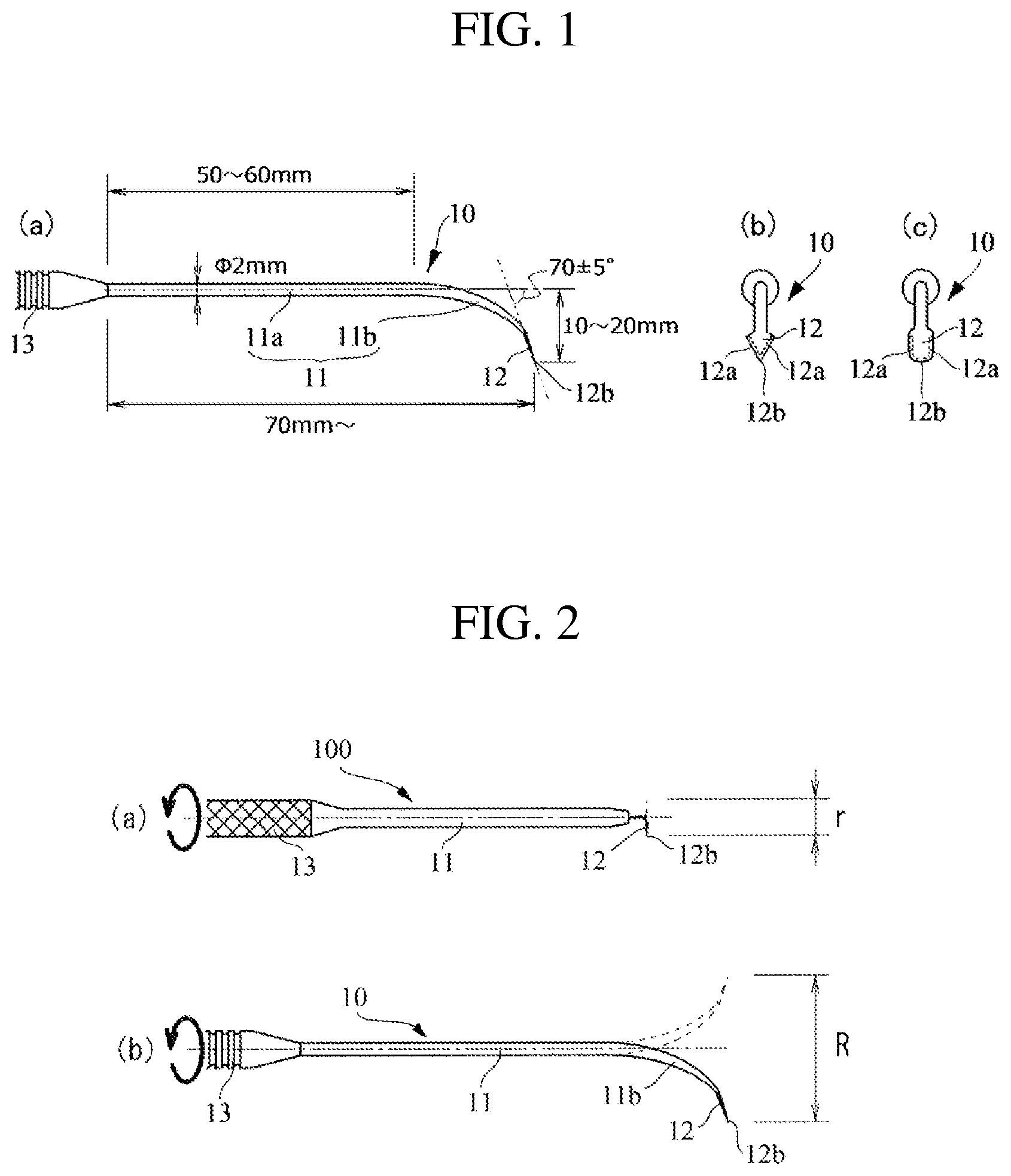
FIG. 1 shows diagrams for describing a nose knife of the present invention, wherein (a) is a side view thereof, (b) is a front view thereof, and (c) is a front view of a different blade form;
FIG. 2 shows diagrams comparing incision ranges of nose knives, wherein (a) is a conventional nose knife and (b) is the nose knife of the present invention;
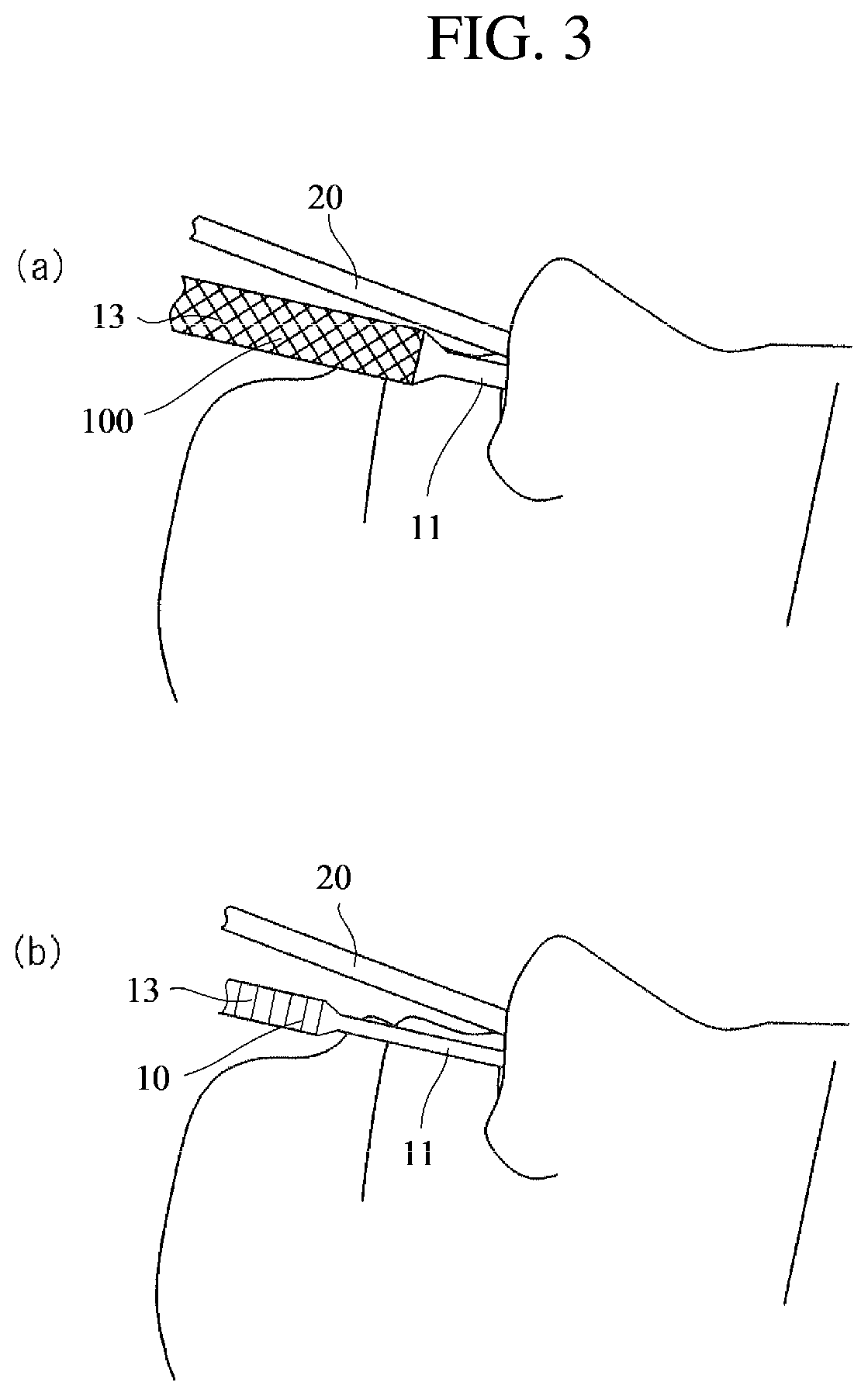
FIG. 3 shows diagrams describing states where an endoscope and a nose knife are inserted in a nostril, wherein (a) is a conventional nose knife and (b) is the nose knife of the present invention; and
FIG. 4 shows diagrams exemplifying conventionally used nose knives (a) and (b).
DESCRIPTION OF EMBODIMENTS
An embodiment according to the present invention is described below with reference to the accompanying drawings.
FIG. 1 shows diagrams for describing a nose knife of the present invention, wherein FIG. 1(a) is a side view thereof, FIG. 1(b) is a front view thereof, and FIG. 1(c) is a front view of a different blade form. A general structure of this nose knife 10 includes a handle 13, a shank 11, and a blade 12.
The handle 13 is a part for a surgeon to grasp during nasal cavity surgery, and is often subjected to non-slip processing. Note that the structure of a non-slip surface is not particularly limited since there are various non-slip processing methods. Moreover, since the nose knife 10 may be rotated around the axis of the handle 13 so as to make an incision, it is good that the cross-section of the handle 13 has a circular shape.
The shank 11 is made up of a straight part 11a connected straight to the handle 13 along the same axis thereof, and a curved part 11b integrally connected to the front end of the straight part 11a. Length of the straight part 11a is preferably 50 to 60 mm, and the entire length of the curved part 11b and the blade 12 added thereto is 70 mm or greater. There is a merit that the longer the length of the shank 11, the further into the nasal cavity the blade 12 reaches; however, if it is too long, usability is degraded, and therefore the resulting optimal length of the straight part 11a is 50 to 60 mm. Note that this length is long enough for the nose knife, allowing it to be used to incise and pare off portions that could not be reached in the past.
The cross-sectional shape of the straight part 11a is preferably a circle with a basic diameter of 2.0 mm within the range of 1.5 to 2.5 mm. This size of the straight part 11a has a small cross section, thereby allowing reduction in mutual interference between the nose knife and the endoscope when they are inserted into a nostril. However, a problem of strength occurs if it is too narrow, and thus the smallest value of the diameter is set to 1.5 mm.
While both of the blades 12 illustrated in FIGS. 1(b) and 1(c) are connected integrally to the front end of the curved part 11b, the blade 12 illustrated in FIG. 1(b) is provided with cutting edges 12a in two directions from a pointed end, and the blade 12 illustrated in FIG. 1(c) is provided with U-shaped cutting edges 12a. In this case, for the pointed cutting edges 12a, a blade tip 12b is a pointed end of the cutting edges 12a, and for the U-shaped cutting edges 12a, it indicates a location farthest from front ends of the curved part 11b at the bottom side of the U. The shape of the blade 12 itself is not particularly limited and may be either one of FIGS. 1(b) and 1(c); however, assuming that the blade tip 12b passes first through body tissue to make an incision, etc., it is preferred that the direction of the blade tip 12b of the blade 12 should be at an angle of approximately 70 degrees plus or minus 5 degrees to the axis direction of the straight part 11a. However, the angle may be set to approximately 90 degrees according to conditions such as location of incision or paring off.
Moreover, the blade tip 12b is located 10 to 20 mm away from the central axial line of the straight part 11a in a perpendicular direction. FIG. 2 shows diagrams comparing incision ranges of nose knives, wherein FIG. 2(a) is a conventional nose knife and FIG. 2(b) is the nose knife of the present invention. The diagrams illustrate ranges for incising, etc., when the respective nose knives 100 and 10 are rotated around the axis. While the blade 12 can only be moved within a range r with the conventional nose knife 100, the blade 12 can be moved within a larger range R than the range r with the nose knife 10 having the curved part 11b according to the present invention. In other words, even with the same rotating angle, the nose knife 10 of the present invention may achieve a larger incision range. Note that the incision range is larger as distance from the central axial line of the straight part 11a to the blade tip 12b is larger, but if it is too large, usability of the nose knife 10 is degraded, and curving of the curved part 11b is increased, thereby leading to a problem of strength.
In this case, the distance from the central axial line of the straight part 11a to the blade tip 12b is determined by the bending shape of the curved part 11b and the angle of the blade 12. In the case where an endoscope is not used, shape of the curved part 11b and angle of the blade 12 need to be determined taking into consideration visual performance of the blade 12 during surgery, as with conventional technology.
In this manner, a conclusion has been made that with consideration of balance between incision range and usability, etc., location of the blade tip 12b is preferably within a range of 10 to 20 mm in a perpendicular direction from the central axial line of the straight part 11a, and the angle of the blade 12 is optimally approximately 70 degrees plus or minus 5 degrees to the axis direction of the straight part 11a.
The diameter of the shank 11 of the conventional nose knife is typically approximately 3.0 mm, which is determined so as to ensure flexural capacity because relatively large force is applied when the body tissue of the nasal cavity, etc., are sampled. However, use of an endoscope for nasal cavity surgery has increased in recent years, where in that case, both the nose knife and the endoscope are inserted in the nostril. FIG. 3 shows diagrams describing states where an endoscope and a nose knife are inserted in a nostril, wherein FIG. 3(a) is a conventional nose knife and FIG. 3(b) is the nose knife of the present invention.
Naturally, when both the nose knife 10 and the endoscope 20 are inserted in a nostril, a smaller diameter of the shank 11 of the nose knife 10 is preferred since interference with the endoscope 20 is reduced. Moreover, since the handle 13 typically has a larger cross-section than that of the shank 11, interference between the handle 13 and the endoscope 20 also requires attention. Taking this into consideration, making the shank 11 of the nose knife 10 of the present invention narrower and longer than that of the conventional nose knife 100 reduces interference between the handle 13 and the endoscope 20.
As described above, the nose knife of the present invention has excellent usability, little interference with an endoscope, and secures sufficient strength, thereby providing excellent beneficial effects.
EXPLANATION OF REFERENCE NUMERALS
10: Nose knife
11: Shank
11a: Straight part
11b: Curved part
12: Blade
12a: Cutting edge
12b: Blade tip
13: Handle
20: Endoscope
* * * * *
D00000
D00001
D00002
D00003
XML
uspto.report is an independent third-party trademark research tool that is not affiliated, endorsed, or sponsored by the United States Patent and Trademark Office (USPTO) or any other governmental organization. The information provided by uspto.report is based on publicly available data at the time of writing and is intended for informational purposes only.
While we strive to provide accurate and up-to-date information, we do not guarantee the accuracy, completeness, reliability, or suitability of the information displayed on this site. The use of this site is at your own risk. Any reliance you place on such information is therefore strictly at your own risk.
All official trademark data, including owner information, should be verified by visiting the official USPTO website at www.uspto.gov. This site is not intended to replace professional legal advice and should not be used as a substitute for consulting with a legal professional who is knowledgeable about trademark law.