Field drainage system and method
Schletzbaum September 29, 2
U.S. patent number 10,787,784 [Application Number 16/565,382] was granted by the patent office on 2020-09-29 for field drainage system and method. The grantee listed for this patent is Joseph L. Schletzbaum. Invention is credited to Joseph L. Schletzbaum.
| United States Patent | 10,787,784 |
| Schletzbaum | September 29, 2020 |
Field drainage system and method
Abstract
A field drainage system includes mainline pipes or trunks, which are placed in trenches. Riser assemblies are mounted on the mainline pipes with saddles. The saddles include saddle bases placed on top of the mainline pipe and saddle inlet couplings which communicate with upwardly-open openings in the mainline pipe. The riser assemblies include transitions, which connect to the saddle inlet couplings, and riser extensions which extend upwardly from the riser assembly transitions. The riser transitions can be inverted for measuring cut off lengths of the riser transitions, using the field surface as a guide. Multiple apertures are formed in the riser extension for admitting groundwater for drainage.
| Inventors: | Schletzbaum; Joseph L. (Atchison, KS) | ||||||||||
|---|---|---|---|---|---|---|---|---|---|---|---|
| Applicant: |
|
||||||||||
| Family ID: | 1000005081982 | ||||||||||
| Appl. No.: | 16/565,382 | ||||||||||
| Filed: | September 9, 2019 |
Prior Publication Data
| Document Identifier | Publication Date | |
|---|---|---|
| US 20200080269 A1 | Mar 12, 2020 | |
Related U.S. Patent Documents
| Application Number | Filing Date | Patent Number | Issue Date | ||
|---|---|---|---|---|---|
| 62728259 | Sep 7, 2018 | ||||
| Current U.S. Class: | 1/1 |
| Current CPC Class: | E02B 11/005 (20130101) |
| Current International Class: | E02B 11/00 (20060101) |
References Cited [Referenced By]
U.S. Patent Documents
| 770019 | September 1904 | Neireiter |
| 902104 | October 1908 | Neireiter |
| 5316410 | May 1994 | Blume |
| 5380121 | January 1995 | Schluter |
| 5536420 | July 1996 | Oyzboyd |
| 5810509 | September 1998 | Nahlik et al. |
| 5908266 | June 1999 | Miller |
| 6077423 | June 2000 | Roy |
| 6746179 | June 2004 | Kerkhoff |
| 7264418 | September 2007 | Houck |
| 7473373 | January 2009 | Danler |
| 9045874 | June 2015 | Kondas |
| 2005/0100412 | May 2005 | Houck |
| 2006/0088382 | April 2006 | Nelson |
| 2011/0064521 | March 2011 | Schafer |
| 2011/0174378 | July 2011 | Leung |
| 511677 | Aug 1939 | GB | |||
| 1201854 | Aug 1970 | GB | |||
Attorney, Agent or Firm: Law Office of Mark Brown, LLC Brown; Mark E.
Parent Case Text
CROSS-REFERENCE TO RELATED APPLICATION
This application claims priority in U.S. Provisional Patent Application No. 62/728,259, filed Sep. 7, 2018, which is incorporated herein by reference.
Claims
Having thus described the invention, what is claimed as new and desired to be secured by Letters Patent is:
1. A field drainage system comprising: a subsurface mainline drainage pipe with an upwardly-open inlet opening; a riser assembly including: a saddle including a saddle base overlying said mainline pipe and a saddle inlet coupling extending upwardly from said saddle base and opening into said mainline pipe inlet opening; a riser transition including: a riser transition lower subsection with a lower, open end; a riser transition upper subsection with an open, upper end; a riser extension including: and open lower end received in said transition upper subsection upper end; multiple openings between said riser extension lower and upper ends; and said riser extension configured for extending above grade whereby said openings are exposed for receiving field drainage.
2. The field drainage system according to claim 1 wherein said mainline drainage pipe comprises corrugated pipe.
3. The field drainage system according to claim 1 wherein said saddle base comprises an arcuate section of corrugated pipe overlying said mainline drainage pipe.
4. The field drainage system according to claim 1 wherein said riser transition lower subsection comprises corrugated pipe.
5. The field drainage system according to claim 1 wherein said riser extension includes vertical ribs extending generally parallel to an axis of said riser extension and protruding outwardly from a riser extension outer surface.
6. The field drainage system according to claim 1 wherein said riser transition is configured for being cut to length to accommodate different subsurface depths of said mainline trunk.
7. The field drainage system according to claim 1 wherein said saddle base is secured on said mainline drainage pipe by an encircling connector.
8. The field drainage system according to claim 1 wherein said encircling connector comprises a hose clamp.
9. The field drainage system according to claim 1 wherein said encircling connector comprises a twist tie.
10. The field drainage system according to claim 1, which includes multiple mainline pipes buried in subsurface trenches at spaced intervals in said field, and multiple riser assemblies mounted on and draining into each mainline pipe.
11. A field drainage system comprising: a subsurface mainline corrugated drainage pipe with an upwardly-open inlet opening; a riser assembly including: a corrugated pipe saddle including a saddle base comprises an arcuate section of corrugated pipe overlying said mainline drainage pipe saddle base overlying said mainline pipe and a saddle inlet coupling extending upwardly from said saddle base and opening into said mainline pipe inlet opening; a riser transition including: a corrugated pipe riser transition lower subsection with a lower, open end; a riser transition upper subsection with an open, upper end; a riser extension including: and open lower end received in said transition upper subsection upper end; a closed upper end; multiple openings between said riser extension lower and upper ends; and vertical ribs extending generally parallel to an axis of said riser extension and protruding outwardly from a riser extension outer surface; said riser extension configured for extending above grade whereby said openings are exposed for receiving field drainage; said riser transition is configured for being cut to length to accommodate different subsurface depths of said mainline trunk; and said saddle base being secured on said mainline drainage pipe by an encircling connector.
12. The field drainage system according to claim 11 wherein said encircling connector comprises a hose clamp.
13. The field drainage system according to claim 11 wherein said encircling connector comprises a twist tie.
14. A method of draining a field, which includes the steps of: providing multiple mainline pipes; providing each said mainline pipe with an upwardly-open inlet opening; burying said mainline pipes in subsurface trenches at spaced intervals in said field; providing multiple riser assemblies each mounted on and draining into each mainline pipe a subsurface mainline drainage pipe; providing each riser assembly with: a saddle including a saddle base overlying said mainline pipe and a saddle inlet coupling extending upwardly from said saddle base and opening into said mainline pipe inlet opening; a riser transition including: a riser transition lower subsection with a lower, open end; a riser transition upper subsection with an open, upper end; a riser extension including: and and open lower end received in said transition upper subsection upper end; multiple openings between said riser extension lower and upper ends; and extending each said riser extension above grade whereby said openings are exposed for receiving field drainage; with said mainline drainpipe placed in a trench, placing said riser section upside down in said saddle inlet coupling; cutting said transition section at field grade; and inverting said transition section.
15. The field drainage method according to claim 14 wherein said mainline drainage pipe comprises corrugated pipe.
16. The field drainage method according to claim 14 wherein said saddle base comprises an arcuate section of corrugated pipe overlying said mainline drainage pipe.
17. The field drainage method according to claim 14 wherein said riser transition lower subsection comprises corrugated pipe.
18. The field drainage method according to claim 14 wherein said riser extension includes vertical ribs extending generally parallel to an axis of said riser extension and protruding outwardly from a riser extension outer surface.
19. The field drainage method according to claim 14 wherein said riser transition is configured for being cut to length to accommodate different subsurface depths of said mainline trunk.
20. The field drainage method according to claim 14, which includes the additional step of connecting said saddle base to said mainline drainage pipe.
Description
BACKGROUND OF THE INVENTION
1. Field of the Invention
The present invention relates generally to field drainage systems and methods, and in particular to a drainage network including subsurface trunk lines fed by risers extending above grade.
2. Description of the Related Art
Agricultural fields and other areas benefit from effective drainage. For example, topsoil conservation is important in many areas. Uncontrolled drainage can cause erosion problems and loss of topsoil, which is important to the productivity of agricultural operations. Such systems should accommodate a variety of field topographies and be easily adaptable with drainage lines (e.g., trunks) that can be installed at different depths below grade.
Heretofore there has not been available a field drainage system or method with the advantages and features of the present invention.
BRIEF SUMMARY OF THE INVENTION
The present invention generally provides a system and method for effectively draining agricultural and other fields, which can efficiently be installed and accommodate a variety of field topographies.
BRIEF DESCRIPTION OF THE DRAWINGS
The drawings constitute a part of this specification and include exemplary embodiments of the present invention illustrating various objects and features thereof.
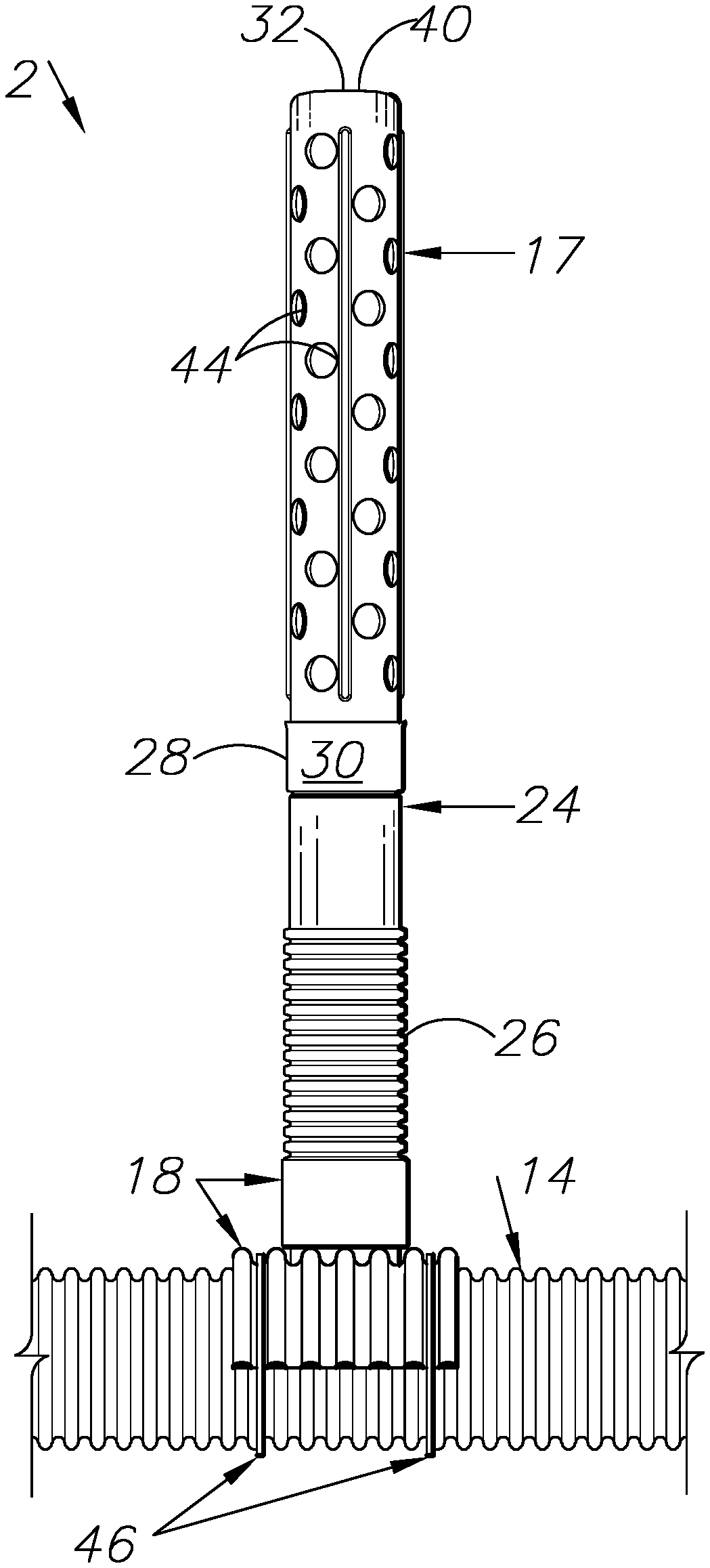
FIG. 1 is a side elevational view of a field drainage system embodying an aspect or embodiment of the present invention.
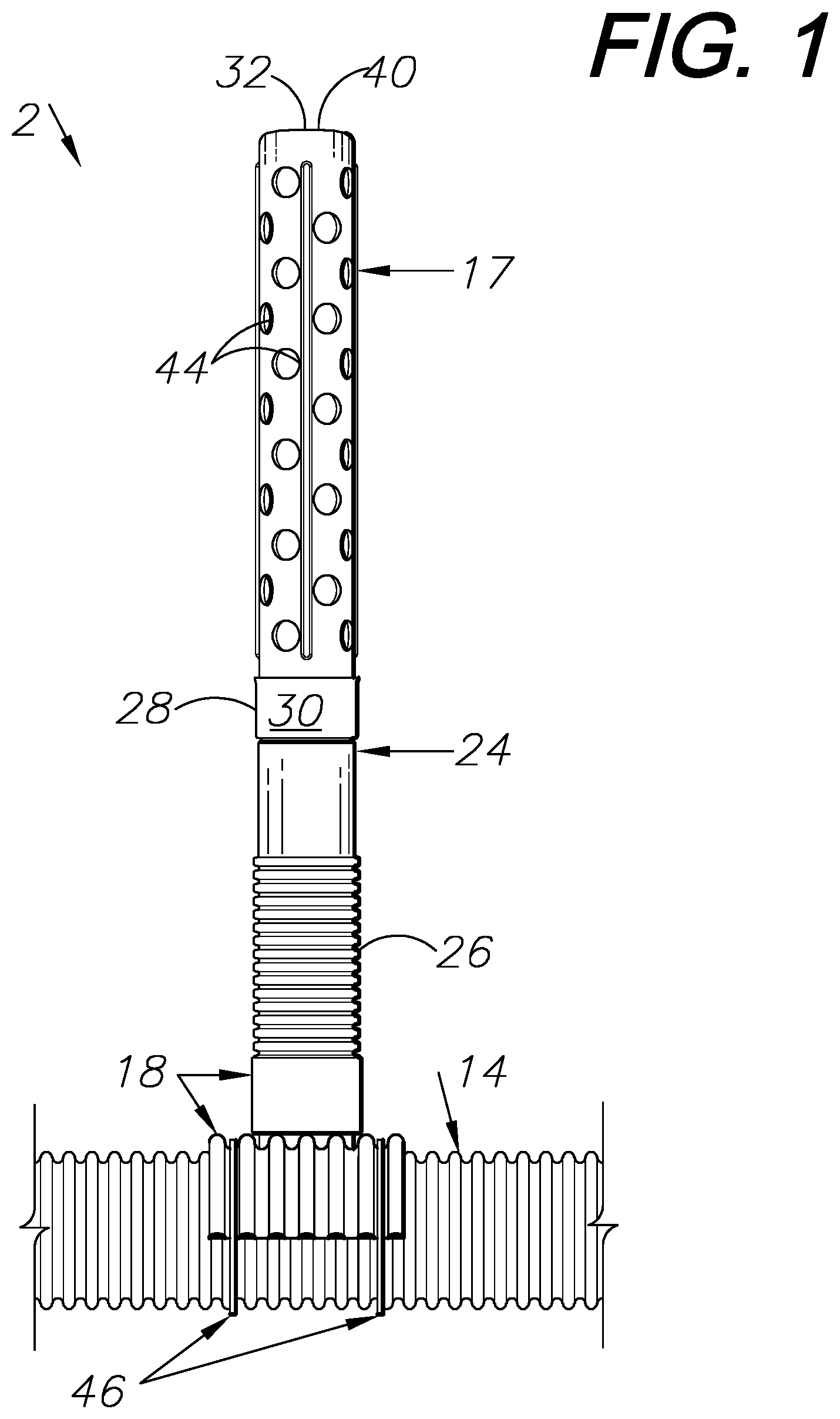
FIG. 2 is an exploded, side elevational view of the field drainage system.
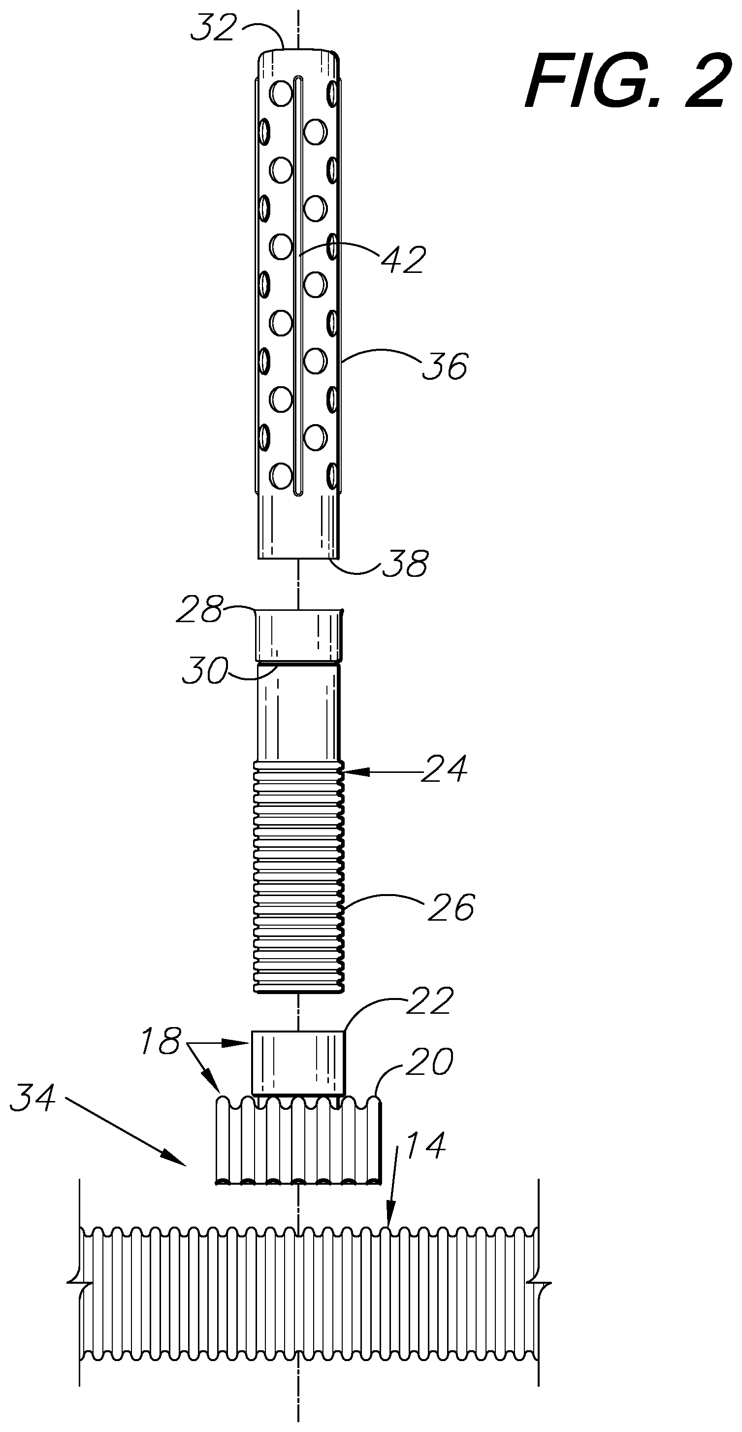
FIG. 3 is a perspective of a portion of the field drainage system.
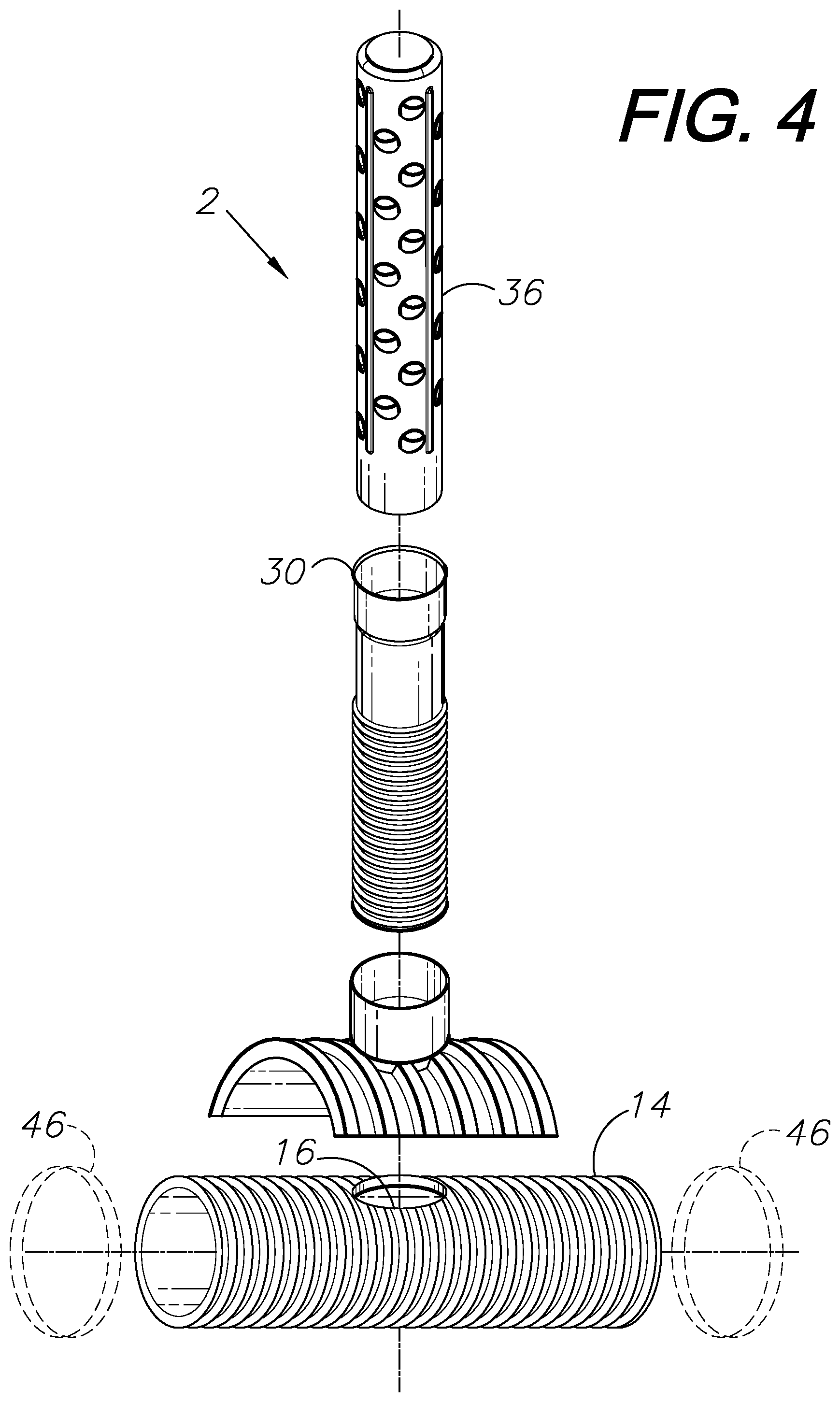
FIG. 4 is an exploded, perspective view of the field drainage system.
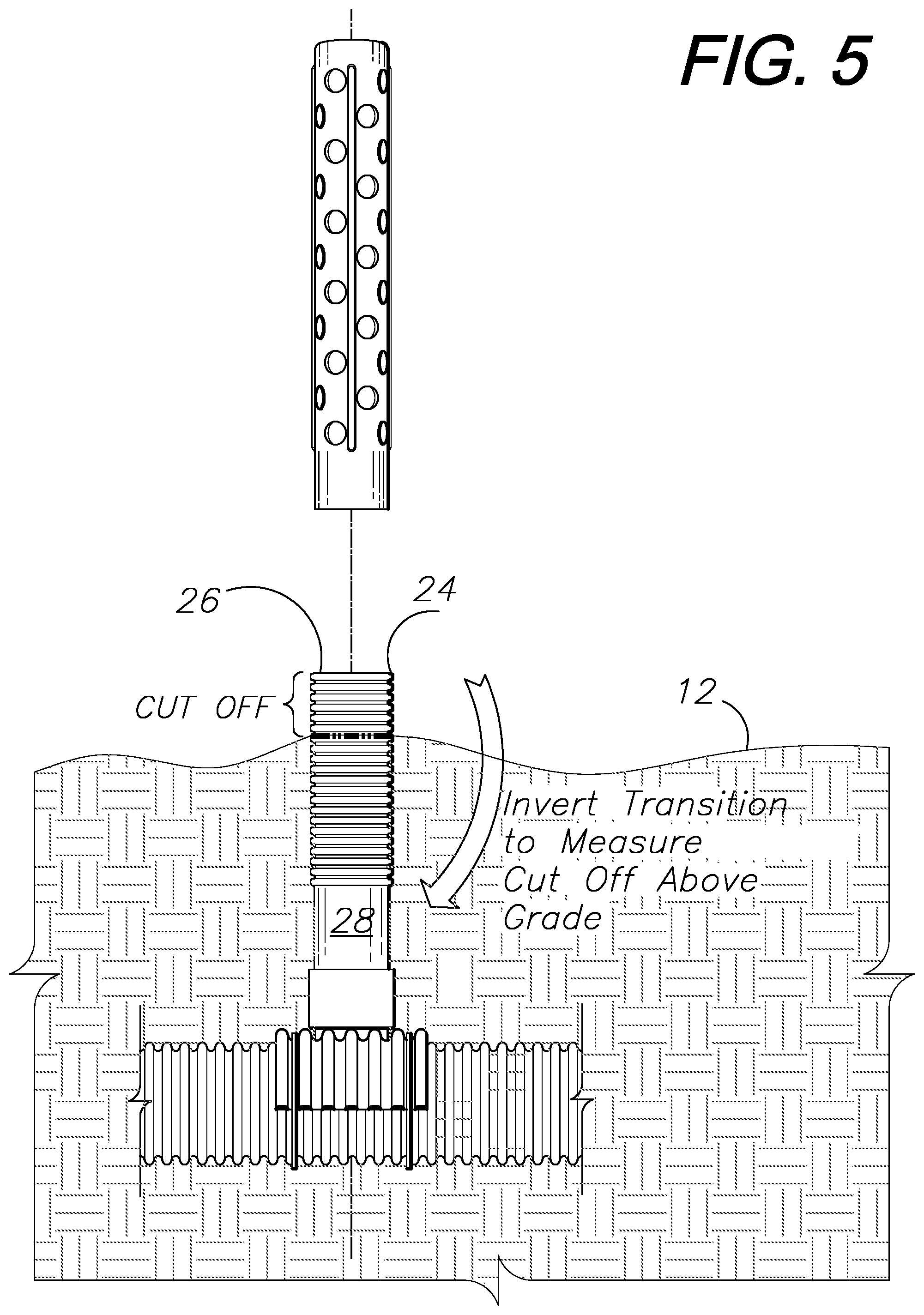
FIG. 5 shows the field drainage system installed with a riser extension inverted for measuring a cut-off location to remove excess length.
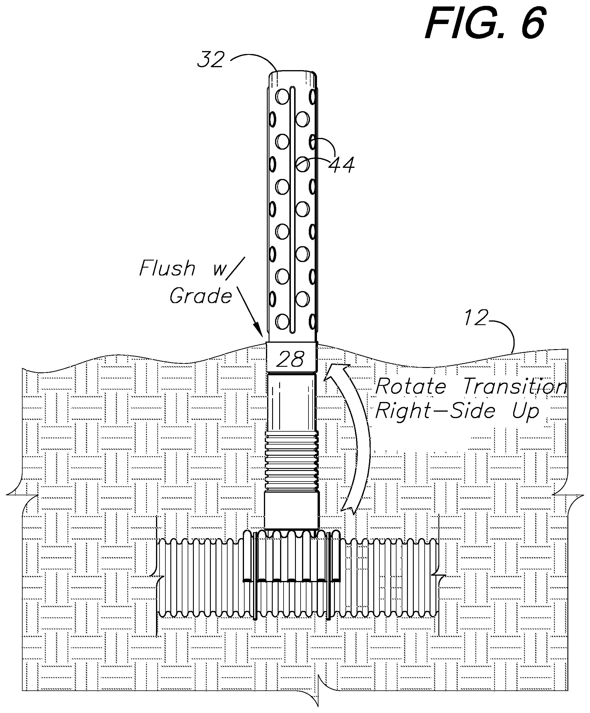
FIG. 6 shows the field drainage system with the riser extension right-side-up.
DETAILED DESCRIPTION OF THE PREFERRED EMBODIMENTS
I. Introduction and Environment
As required, detailed aspects of the present invention are disclosed herein, however, it is to be understood that the disclosed aspects are merely exemplary of the invention, which may be embodied in various forms. Therefore, specific structural and functional details disclosed herein are not to be interpreted as limiting, but merely as a basis for the claims and as a representative basis for teaching one skilled in the art how to variously employ the present invention in virtually any appropriately detailed structure.
Certain terminology will be used in the following description for convenience in reference only and will not be limiting. For example, up, down, front, back, right and left refer to the invention as orientated in the view being referred to. The words, "inwardly" and "outwardly" refer to directions toward and away from, respectively, the geometric center of the aspect being described and designated parts thereof. Forwardly and rearwardly are generally in reference to the direction of travel, if appropriate. Said terminology will include the words specifically mentioned, derivatives thereof and words of similar meaning.
II. Preferred Embodiment
As shown in the drawings, a field drainage system 2 embodying an aspect of the present invention can be installed in fields 12 and other areas requiring surface water and runoff drainage. Main lines or trunks 14 are laid in excavated trenches at an appropriate depth. The main lines 14 include openings 16 located at spaced intervals and oriented upwardly.
A respective riser assembly 17 is placed over and communicates with each trunk opening 16. Each riser assembly 17 includes a saddle 18 with an arcuate saddle base 20 and a coupling 22 extending downwardly through the base 20 and extending upwardly from the saddle base 20. The coupling 22 defines an inside diameter. A riser extension 24 of the riser assembly 17 includes a lower, corrugated subsection 26 and an upper, smooth-walled subsection 28, which includes an annular, inwardly-extending stop 30 spaced slightly below an upper end 32 of the riser extension 17. A lower end 34 of the riser extension 17 is telescopically received in the saddle coupling 22.
The riser assembly 17 further includes a riser extension 36 with an open, lower end 38 received in the saddle inlet coupling 22 and a closed, upper end 40. Vertical ribs 42 extend longitudinally along the riser extension 36 between its ends 38, 40 and facilitate sloughing trash and other debris. Moreover, the vertical ribs strengthen the riser extensions 36. Water is admitted into the riser extension 36 through openings 44. Each opening 44 is preferably about two inches in diameter, which allows relatively small debris objects to flow into the riser extension 36, and blocks larger objects, such as plant stalks and other field debris (i.e., "field trash"). The riser extension is preferably designed to minimize trash wraparound, which could interfere with field drainage.
When the system is installed, the riser extension 24 can be inverted (FIG. 5) and the grade level can be used to determine the excess length of riser extension 24 to cut off. For final installation the riser extension 24 is placed right-side-up (FIG. 6) and its corrugated, lower end 34 is received in the saddle inlet coupling 22.
The saddle 18 can optionally be secured to the trunk line 14 by an encircling connector 46 (FIGS. 1, 5, 6). Without limitation, the encircling connector 46 can comprise a hose clamp or a twist tie. Alternatively, the saddle 18 can be secured to the trunk line 14 by fasteners, such as screws, wires and other fasteners.
The components of the field drainage system can be installed in various configurations to accommodate field conditions. For example, the pipe section diameters can vary based on anticipated drainage flow, field trash and other variables. Depending on the depth of the main line (trunk) 14, one or more additional riser extension(s) 24 can be installed. For example, with the main or trunk line 14 buried relatively deeply below grade 12, such an extended riser extension (or sections) 24 of dual-wall pipe may be needed to elevate the riser extension 36 to a proper elevation above finished grade 12. The riser extensions 24 can comprise dual-wall corrugated pipe, similar to the lower subsection 26 of the riser extension 24. Fields 12 can be provided with multiple trunks 14, each receiving runoff and standing water from multiple riser assemblies 17. Networks of such drainage system components can be placed for gravity drainage. For example, the trunks 14 can drain to natural watercourses, ponds, lakes, streams, rivers, etc., or to lower-elevation areas for additional draining, surface application, pumping, etc.
The drainage system 2 is usable in both tillage and no-till applications, and in terraced and non-terraced fields. The components of the system 2 can comprise any suitable material, such as high-density polyethylene (HDPE) plastic.
It is to be understood that while certain embodiments and/or aspects of the invention have been shown and described, the invention is not limited thereto and encompasses various other embodiments and aspects.
* * * * *
D00000
D00001
D00002
D00003
D00004
D00005
D00006
XML
uspto.report is an independent third-party trademark research tool that is not affiliated, endorsed, or sponsored by the United States Patent and Trademark Office (USPTO) or any other governmental organization. The information provided by uspto.report is based on publicly available data at the time of writing and is intended for informational purposes only.
While we strive to provide accurate and up-to-date information, we do not guarantee the accuracy, completeness, reliability, or suitability of the information displayed on this site. The use of this site is at your own risk. Any reliance you place on such information is therefore strictly at your own risk.
All official trademark data, including owner information, should be verified by visiting the official USPTO website at www.uspto.gov. This site is not intended to replace professional legal advice and should not be used as a substitute for consulting with a legal professional who is knowledgeable about trademark law.