Strengthening variable thickness glass
Weber Sept
U.S. patent number 10,781,135 [Application Number 13/235,036] was granted by the patent office on 2020-09-22 for strengthening variable thickness glass. This patent grant is currently assigned to APPLE INC.. The grantee listed for this patent is Douglas J. Weber. Invention is credited to Douglas J. Weber.


| United States Patent | 10,781,135 |
| Weber | September 22, 2020 |
Strengthening variable thickness glass
Abstract
Apparatus, systems and methods for increasing the strength of glass are disclosed. The use of multi-bath chemical processing for a glass article can facilitate controlled chemical strengthening. Through multi-bath (or multi-step) chemical processing, differing levels of strengthening can be achieved for different portion of glass articles. The multi-bath chemical processing can be achieved through the use of successive chemical baths. Accordingly, glass articles that have undergone multi-bath chemical processing are able to be not only thin but also sufficiently strong and resistant to damage. The strengthened glass articles are well suited for use in consumer products, such as consumer electronic devices (e.g., portable electronic devices). In one embodiment, the glass member can pertain to a glass cover for a housing of an electronic device.
| Inventors: | Weber; Douglas J. (Arcadia, CA) | ||||||||||
|---|---|---|---|---|---|---|---|---|---|---|---|
| Applicant: |
|
||||||||||
| Assignee: | APPLE INC. (Cupertino,
CA) |
||||||||||
| Family ID: | 1000005068132 | ||||||||||
| Appl. No.: | 13/235,036 | ||||||||||
| Filed: | September 16, 2011 |
Prior Publication Data
| Document Identifier | Publication Date | |
|---|---|---|
| US 20120236526 A1 | Sep 20, 2012 | |
Related U.S. Patent Documents
| Application Number | Filing Date | Patent Number | Issue Date | ||
|---|---|---|---|---|---|
| 61453398 | Mar 16, 2011 | ||||
| Current U.S. Class: | 1/1 |
| Current CPC Class: | C03C 21/002 (20130101) |
| Current International Class: | C03C 21/00 (20060101) |
| Field of Search: | ;65/30.1,30.13,30.14,111,114-116 |
References Cited [Referenced By]
U.S. Patent Documents
| 2643020 | June 1953 | Dalton |
| 3415637 | December 1968 | Glynn |
| 3441398 | April 1969 | Hess |
| 3467508 | September 1969 | Loukes et al. |
| 3498773 | March 1970 | Due et al. |
| 3558415 | January 1971 | Rieser et al. |
| 3607172 | September 1971 | Poole et al. |
| 3619240 | November 1971 | Toussaint et al. |
| 3626723 | December 1971 | Plumat |
| 3652244 | March 1972 | Plumat |
| 3753840 | August 1973 | Plumat |
| 3798013 | March 1974 | Inoue et al. |
| 3843472 | October 1974 | Toussaint et al. |
| 3857689 | December 1974 | Koizumi et al. |
| 3926605 | December 1975 | Kunkle |
| 3951707 | April 1976 | Kurtz et al. |
| 4015045 | March 1977 | Rinehart |
| 4052184 | October 1977 | Anderson |
| 4119760 | October 1978 | Rinehart |
| 4156755 | May 1979 | Rinehart |
| 4165228 | August 1979 | Ebata et al. |
| 4148082 | December 1979 | Ganswein et al. |
| 4212919 | July 1980 | Hoda |
| 4218230 | August 1980 | Hogan |
| 4346601 | August 1982 | France |
| 4353649 | October 1982 | Kishii |
| 4425810 | January 1984 | Simon et al. |
| 4537820 | August 1985 | Nowobliski et al. |
| 4646722 | March 1987 | Silverstein et al. |
| 4733973 | March 1988 | Machak et al. |
| 4842629 | June 1989 | Clemens et al. |
| 4844724 | July 1989 | Sakai et al. |
| 4846868 | July 1989 | Aratani |
| 4849002 | July 1989 | Rapp |
| 4872896 | October 1989 | LaCourse et al. |
| 4911743 | March 1990 | Bagby |
| 4937129 | June 1990 | Yamazaki |
| 4957364 | September 1990 | Chesler |
| 4959548 | September 1990 | Kupperman et al. |
| 4983197 | January 1991 | Froning et al. |
| 4986130 | January 1991 | Engelhaupt et al. |
| 5041173 | August 1991 | Shikata et al. |
| 5104435 | April 1992 | Oikawa et al. |
| 5129934 | July 1992 | Koss |
| 5157746 | October 1992 | Tobita et al. |
| 5160523 | November 1992 | Honkanen et al. |
| 5254149 | October 1993 | Hashemi et al. |
| 5269888 | December 1993 | Morasca |
| 5281303 | January 1994 | Beguin et al. |
| 5369267 | November 1994 | Johnson et al. |
| 5411563 | May 1995 | Yeh |
| 5437193 | August 1995 | Schleitweiler et al. |
| 5445871 | August 1995 | Murase et al. |
| 5483261 | January 1996 | Yasutake |
| 5488204 | January 1996 | Mead et al. |
| 5525138 | June 1996 | Hashemi et al. |
| 5625154 | April 1997 | Matsuhiro et al. |
| 5654057 | August 1997 | Kitayama |
| 5725625 | March 1998 | Kitayama et al. |
| 5733622 | March 1998 | Starcke et al. |
| 5766493 | June 1998 | Shin |
| 5780371 | July 1998 | Rifqi et al. |
| 5816225 | October 1998 | Koch et al. |
| 5825352 | October 1998 | Bisset et al. |
| 5826601 | October 1998 | Muraoka et al. |
| 5835079 | November 1998 | Shieh |
| 5880411 | March 1999 | Gillespie et al. |
| 5930047 | July 1999 | Gunz et al. |
| 5953094 | September 1999 | Matsuoka et al. |
| 5985014 | November 1999 | Ueda et al. |
| 6050870 | April 2000 | Suginoya et al. |
| 6114039 | September 2000 | Rifqui |
| 6120908 | September 2000 | Papanu et al. |
| 6166915 | December 2000 | Lake et al. |
| 6188391 | February 2001 | Seely et al. |
| 6245313 | June 2001 | Suzuki et al. |
| 6287674 | September 2001 | Verlinden et al. |
| 6307590 | October 2001 | Yoshida |
| 6310610 | October 2001 | Beaton et al. |
| 6323846 | November 2001 | Westerman et al. |
| 6325704 | December 2001 | Brown et al. |
| 6327011 | December 2001 | Kim |
| 6350664 | February 2002 | Haji et al. |
| 6393180 | May 2002 | Farries et al. |
| 6429840 | August 2002 | Sekiguchi |
| 6516634 | February 2003 | Green et al. |
| 6521862 | February 2003 | Brannon |
| 6621542 | September 2003 | Aruga |
| 6690387 | February 2004 | Zimmerman et al. |
| 6718612 | April 2004 | Bajorek |
| 6769274 | August 2004 | Cho et al. |
| 6772610 | August 2004 | Albrand et al. |
| 6810688 | November 2004 | Duisit et al. |
| 6936741 | August 2005 | Munnig et al. |
| 6955971 | October 2005 | Ghyselen et al. |
| 6996324 | February 2006 | Hiraka et al. |
| 7012700 | March 2006 | De Groot et al. |
| 7013709 | March 2006 | Hajduk et al. |
| 7015894 | March 2006 | Morohoshi |
| 7070837 | July 2006 | Ross |
| 7166531 | January 2007 | Van Den Hoek et al. |
| 7184064 | February 2007 | Zimmerman et al. |
| 7461564 | December 2008 | Glaesemann |
| 7558054 | July 2009 | Prest et al. |
| 7626807 | December 2009 | Hsu |
| 7663607 | February 2010 | Hotelling et al. |
| 7810355 | October 2010 | Feinstein et al. |
| 7872644 | January 2011 | Hong et al. |
| 7918019 | April 2011 | Chang et al. |
| 8013834 | September 2011 | Kim |
| 8110268 | February 2012 | Hegemier et al. |
| 8111248 | February 2012 | Lee et al. |
| 8312743 | November 2012 | Pun et al. |
| 8391010 | March 2013 | Rothkopf |
| 8393175 | March 2013 | Kohli et al. |
| 8551283 | October 2013 | Pakula et al. |
| 8673163 | March 2014 | Zhong |
| 8684613 | April 2014 | Weber et al. |
| 8824140 | September 2014 | Prest |
| 9128666 | September 2015 | Werner |
| 2002/0035853 | March 2002 | Brown et al. |
| 2002/0105793 | August 2002 | Oda |
| 2002/0155302 | October 2002 | Smith et al. |
| 2002/0157199 | October 2002 | Piltingsrud |
| 2003/0024274 | February 2003 | Cho et al. |
| 2003/0057183 | March 2003 | Cho et al. |
| 2003/0077453 | July 2003 | Oaku et al. |
| 2003/0234771 | December 2003 | Mulligan et al. |
| 2004/0051944 | March 2004 | Stark |
| 2004/0119701 | June 2004 | Mulligan et al. |
| 2004/0137828 | July 2004 | Takashashi et al. |
| 2004/0142118 | July 2004 | Takechi |
| 2004/0163414 | August 2004 | Eto et al. |
| 2005/0058423 | March 2005 | Brinkmann et al. |
| 2005/0105071 | May 2005 | Ishii |
| 2005/0135724 | June 2005 | Helvajian et al. |
| 2005/0174525 | August 2005 | Tsuboi |
| 2005/0193772 | September 2005 | Davidson et al. |
| 2005/0245165 | November 2005 | Harada et al. |
| 2005/0259438 | November 2005 | Mizutani |
| 2005/0285991 | December 2005 | Yamazaki |
| 2006/0026521 | February 2006 | Hotelling et al. |
| 2006/0055936 | March 2006 | Yun et al. |
| 2006/0063351 | March 2006 | Jain |
| 2006/0070694 | April 2006 | Rehfeld et al. |
| 2006/0097991 | May 2006 | Hotelling et al. |
| 2006/0197753 | September 2006 | Hotelling et al. |
| 2006/0227331 | October 2006 | Wollmer et al. |
| 2006/0238695 | October 2006 | Miyamoto |
| 2006/0250559 | November 2006 | Bocko et al. |
| 2006/0268528 | November 2006 | Zadeksky et al. |
| 2006/0292822 | December 2006 | Xie |
| 2006/0294420 | December 2006 | Schneider |
| 2007/0003796 | January 2007 | Isono et al. |
| 2007/0013822 | January 2007 | Kawata et al. |
| 2007/0029519 | February 2007 | Kikuyama et al. |
| 2007/0030436 | February 2007 | Sasabayashi |
| 2007/0039353 | February 2007 | Kamiya |
| 2007/0046200 | March 2007 | Fu et al. |
| 2007/0063876 | March 2007 | Wong |
| 2007/0089827 | April 2007 | Funatsu |
| 2007/0122542 | May 2007 | Halsey et al. |
| 2007/0132737 | June 2007 | Mulligan et al. |
| 2007/0196578 | August 2007 | Karp et al. |
| 2007/0236618 | October 2007 | Magg et al. |
| 2008/0020919 | January 2008 | Murata |
| 2008/0026260 | January 2008 | Kawai |
| 2008/0074028 | March 2008 | Ozolins et al. |
| 2008/0094716 | April 2008 | Ushiro et al. |
| 2008/0135175 | June 2008 | Higuchi |
| 2008/0158181 | July 2008 | Hamblin et al. |
| 2008/0202167 | August 2008 | Cavallaro et al. |
| 2008/0230177 | September 2008 | Crouser et al. |
| 2008/0243321 | October 2008 | Walser et al. |
| 2008/0261057 | October 2008 | Slobodin |
| 2008/0264176 | October 2008 | Bertrand et al. |
| 2008/0286548 | November 2008 | Ellison et al. |
| 2009/0011803 | January 2009 | Weber et al. |
| 2009/0046240 | February 2009 | Bolton |
| 2009/0067141 | March 2009 | Dabov et al. |
| 2009/0090694 | April 2009 | Hotelling |
| 2009/0091551 | April 2009 | Hotelling et al. |
| 2009/0096937 | April 2009 | Bauer et al. |
| 2009/0153729 | June 2009 | Hiltunen et al. |
| 2009/0162703 | June 2009 | Kawai |
| 2009/0197048 | August 2009 | Amin et al. |
| 2009/0202808 | August 2009 | Glaesemann et al. |
| 2009/0220761 | September 2009 | Dejneka et al. |
| 2009/0257189 | October 2009 | Wang et al. |
| 2009/0324899 | December 2009 | Feinstein et al. |
| 2009/0324939 | December 2009 | Feinstein et al. |
| 2010/0009154 | January 2010 | Allan et al. |
| 2010/0024484 | February 2010 | Kashima |
| 2010/0028607 | February 2010 | Lee et al. |
| 2010/0062284 | March 2010 | Watanabe et al. |
| 2010/0119846 | May 2010 | Sawada |
| 2010/0137031 | June 2010 | Griffin et al. |
| 2010/0154992 | June 2010 | Feinstein et al. |
| 2010/0167059 | July 2010 | Hasimoto et al. |
| 2010/0171920 | July 2010 | Nishiyama |
| 2010/0179044 | July 2010 | Sellier et al. |
| 2010/0206008 | August 2010 | Harvey et al. |
| 2010/0215862 | August 2010 | Gomez et al. |
| 2010/0216514 | August 2010 | Smoyer et al. |
| 2010/0224767 | September 2010 | Kawano et al. |
| 2010/0265188 | October 2010 | Chang et al. |
| 2010/0279067 | November 2010 | Sabia et al. |
| 2010/0285275 | November 2010 | Baca et al. |
| 2010/0296027 | November 2010 | Matsuhira et al. |
| 2010/0315570 | December 2010 | Dinesh et al. |
| 2010/0315909 | December 2010 | Altenhoven et al. |
| 2010/0321305 | December 2010 | Chang et al. |
| 2011/0003619 | January 2011 | Bolton |
| 2011/0012873 | January 2011 | Prest et al. |
| 2011/0019123 | January 2011 | Prest |
| 2011/0019354 | January 2011 | Prest et al. |
| 2011/0030209 | February 2011 | Chang et al. |
| 2011/0050657 | March 2011 | Yamada |
| 2011/0063550 | March 2011 | Gettemy et al. |
| 2011/0067447 | March 2011 | Zadesky et al. |
| 2011/0072856 | March 2011 | Davidson et al. |
| 2011/0102346 | May 2011 | Orsley et al. |
| 2011/0159321 | June 2011 | Eda et al. |
| 2011/0164372 | July 2011 | McClure et al. |
| 2011/0182084 | July 2011 | Tomlinson |
| 2011/0186345 | August 2011 | Pakula et al. |
| 2011/0188846 | August 2011 | Sorg |
| 2011/0199687 | August 2011 | Sellier et al. |
| 2011/0248152 | October 2011 | Svajda et al. |
| 2011/0255000 | October 2011 | Weber et al. |
| 2011/0255250 | October 2011 | Dinh |
| 2011/0267833 | November 2011 | Verrat-Debailleul et al. |
| 2011/0279383 | November 2011 | Wilson et al. |
| 2011/0300908 | December 2011 | Grespan et al. |
| 2012/0018323 | January 2012 | Johnson et al. |
| 2012/0027399 | February 2012 | Yeates |
| 2012/0227399 | February 2012 | Yeates |
| 2012/0099113 | April 2012 | de Boer et al. |
| 2012/0105400 | May 2012 | Mathew et al. |
| 2012/0118628 | May 2012 | Pakula et al. |
| 2012/0135195 | May 2012 | Glaesemann et al. |
| 2012/0136259 | May 2012 | Milner et al. |
| 2012/0151760 | June 2012 | Steijner |
| 2012/0188743 | July 2012 | Wilson et al. |
| 2012/0196071 | August 2012 | Cornejo et al. |
| 2012/0202040 | August 2012 | Barefoot et al. |
| 2012/0236477 | September 2012 | Weber et al. |
| 2012/0236526 | September 2012 | Weber et al. |
| 2012/0281381 | November 2012 | Sanford |
| 2012/0328843 | December 2012 | Cleary et al. |
| 2013/0071601 | March 2013 | Bibl et al. |
| 2013/0083506 | April 2013 | Wright et al. |
| 2013/0213565 | August 2013 | Lee et al. |
| 2014/0176779 | June 2014 | Weber et al. |
| 283 630 | Oct 1970 | AT | |||
| 1369449 | Sep 2002 | CN | |||
| 1672468 | Sep 2005 | CN | |||
| 1693247 | Nov 2005 | CN | |||
| 1694589 | Nov 2005 | CN | |||
| 101025502 | Aug 2007 | CN | |||
| 101206314 | Jun 2008 | CN | |||
| 101939266 | Jan 2011 | CN | |||
| 102117104 | Jul 2011 | CN | |||
| 102131357 | Jul 2011 | CN | |||
| 101267509 | Aug 2011 | CN | |||
| 102591576 | Jul 2012 | CN | |||
| 202799425 | Mar 2013 | CN | |||
| 103958423 | Jul 2014 | CN | |||
| 14 96 586 | Jun 1969 | DE | |||
| 17 71 268 | Dec 1971 | DE | |||
| 32 12 612 | Oct 1983 | DE | |||
| 103 22 350 | Dec 2004 | DE | |||
| 1038663 | Sep 2000 | EP | |||
| 1 206 422 | Nov 2002 | EP | |||
| 1 593 658 | Nov 2005 | EP | |||
| 1592073 | Nov 2005 | EP | |||
| 2025556 | Feb 2009 | EP | |||
| 2036867 | Mar 2009 | EP | |||
| 2075237 | Jul 2009 | EP | |||
| 2233447 | Sep 2010 | EP | |||
| 2483216 | Aug 2012 | EP | |||
| 2635540 | Sep 2013 | EP | |||
| 2 797 627 | Feb 2001 | FR | |||
| 2 801 302 | May 2001 | FR | |||
| 1 346 747 | Feb 1974 | GB | |||
| B S42-011599 | Jun 1963 | JP | |||
| B-S48-006925 | Mar 1973 | JP | |||
| 52031757 | Mar 1977 | JP | |||
| 55 067529 | May 1980 | JP | |||
| 55-95645 | Jul 1980 | JP | |||
| A S55-136979 | Oct 1980 | JP | |||
| 55 144450 | Nov 1980 | JP | |||
| A S59-013638 | Jan 1984 | JP | |||
| A S61-097147 | May 1986 | JP | |||
| 63 060129 | Mar 1988 | JP | |||
| AS63106617 | May 1988 | JP | |||
| 05249422 | Sep 1993 | JP | |||
| 6242260 | Sep 1994 | JP | |||
| A H07-050144 | Feb 1995 | JP | |||
| Hei 8-274054 | Oct 1996 | JP | |||
| 52031757 | Mar 1997 | JP | |||
| A-H09-073072 | Mar 1997 | JP | |||
| A H09-507206 | Jul 1997 | JP | |||
| 09-312245 | Dec 1997 | JP | |||
| A H11-281501 | Oct 1999 | JP | |||
| A 2000-086261 | Mar 2000 | JP | |||
| 2000-163031 | Jun 2000 | JP | |||
| 2002/03895 | Jul 2000 | JP | |||
| 200203895 | Jul 2000 | JP | |||
| A 2001-083887 | Mar 2001 | JP | |||
| A 2002-160932 | Jun 2002 | JP | |||
| 2002-342033 | Nov 2002 | JP | |||
| A 2002-338283 | Nov 2002 | JP | |||
| A2003502257 | Jan 2003 | JP | |||
| A 2004-094256 | Mar 2004 | JP | |||
| A2004-339019 | Dec 2004 | JP | |||
| 2005162549 | Jun 2005 | JP | |||
| A 2005-156766 | Jun 2005 | JP | |||
| A 2005140901 | Jun 2005 | JP | |||
| 2005353592 | Dec 2005 | JP | |||
| A 2000-348338 | Dec 2005 | JP | |||
| 2007-099557 | Apr 2007 | JP | |||
| 2008007360 | Jan 2008 | JP | |||
| 2008-63166 | Mar 2008 | JP | |||
| 2008-192194 | Aug 2008 | JP | |||
| A 2008-195602 | Aug 2008 | JP | |||
| A 2008-216938 | Sep 2008 | JP | |||
| A 2008-306149 | Dec 2008 | JP | |||
| A 2009-167086 | Jul 2009 | JP | |||
| A 2009-234856 | Oct 2009 | JP | |||
| A2009230341 | Oct 2009 | JP | |||
| 2010 064943 | Mar 2010 | JP | |||
| A 2010-060908 | Mar 2010 | JP | |||
| A 2010-116276 | May 2010 | JP | |||
| U3162733 | Aug 2010 | JP | |||
| 2010/195600 | Sep 2010 | JP | |||
| A 2010-237493 | Oct 2010 | JP | |||
| A 2011-032140 | Feb 2011 | JP | |||
| A 2011-158799 | Aug 2011 | JP | |||
| A 2011-231009 | Nov 2011 | JP | |||
| A 2013-537723 | Oct 2013 | JP | |||
| 2010-2006-005920 | Jan 2006 | KR | |||
| 10-2010-0019526 | Feb 2010 | KR | |||
| 10-2011-0030919 | Mar 2011 | KR | |||
| 201007521 | Feb 2010 | TW | |||
| 201235744 | Sep 2012 | TW | |||
| WO 00/47529 | Aug 2000 | WO | |||
| WO 02/42838 | May 2002 | WO | |||
| WO 2004/014109 | Feb 2004 | WO | |||
| WO 2004-061806 | Jul 2004 | WO | |||
| WO 2004/106253 | Dec 2004 | WO | |||
| WO 2007/089054 | Aug 2007 | WO | |||
| WO 2008/143999 | Nov 2008 | WO | |||
| WO 2009/003029 | Dec 2008 | WO | |||
| WO 2009/078406 | Jun 2009 | WO | |||
| WO 2009/102326 | Aug 2009 | WO | |||
| WO 2010/005578 | Jan 2010 | WO | |||
| WO 2010/014163 | Feb 2010 | WO | |||
| WO 2010/019829 | Feb 2010 | WO | |||
| WO 2010/080988 | Jul 2010 | WO | |||
| WO 2010/101961 | Sep 2010 | WO | |||
| WO 2011/008433 | Jan 2011 | WO | |||
| WO2010/027565 | Feb 2011 | WO | |||
| WO 2011/041484 | Apr 2011 | WO | |||
| WO 2012/015960 | Feb 2012 | WO | |||
| WO 2012/027220 | Mar 2012 | WO | |||
| WO 2012/106280 | Aug 2012 | WO | |||
| WO 2013/106242 | Jul 2013 | WO | |||
Other References
|
Chemically Strengthened Glass, Wikipedia, Apr. 19, 2009, http://en/wikipedia.org/w/index.php?title=Chemically_strengthened_glass&o- ldid=284794988. cited by applicant . Wikipedia: "Iphone 4", www.wikipedia.org, retrived Oct. 31, 2011, 15 pgs. cited by applicant . "Toward Making Smart Phone Touch-Screens More Glare and Smudge Resistant", e! Science News, http://eciencenews.com/articles/2009/08/19toward.making.smart.phone.touch- .screens.more.glare.and.smudge.resistant, Aug. 19, 2009, 1 pg. cited by applicant . Arun K. Varshneya, Chemical Strengthening of Glass: Lessons Learned and Yet to be Learned International Journal of Applied Glass Science, 2010, 1, 2, pp. 131-142. cited by applicant . Aben "Laboratory of Photoelasticity", Institute of Cybernetics at TTU, www.ioc.ee/res/photo.html, Oct. 5, 2000. cited by applicant . Forooghian et al., Investigative Ophthalmology & Visual Science; Oct. 2008, vol. 49, No. 10. cited by applicant . International Search Report and Written Opinion for PCT/US2012/029279, dated Jul. 25, 2012. cited by applicant . Office Action for Taiwanese Patent Application No. 101109011, dated Nov. 14, 2013. cited by applicant . Final Office Action for Japanese Patent Application No. 2013-558184, dated Jul. 3, 2015. cited by applicant . Second Notice of Preliminary Rejection for Korean Patent Application No. 10-2013-7024531, dated Aug. 26, 2015. cited by applicant . Kingery et al., "Introduction to Ceramics" 2nd Ed. John Wiley & Sons, 1976, pp. 792 and 833-844. cited by applicant . Office Action for Chinese Patent Application No. 201280013356.8, dated Dec. 31, 2015. cited by applicant . Ohkuma, "Development of a Manufacturing Process of a Thin, Lightweight LCD Cell", Department of Cell Process Development, IBM, Japan, Section 13.4. cited by applicant . Lee et al., "A Multi-Touch Three Dimensional Touch-Sensitive Tablet", Proceedings of CHI: ACM Conference on Human Factors in Computing Systems, Apr. 1985, pp. 21-25. cited by applicant . Rubine, "The Automatic Recognition of Gestures", CMU-CS-91-202, Submitted in Partial Fulfillment of the Requirements of the Degree of Doctor of Philosophy in Computer Science at Carnegie Mellon University, Dec. 1991, 285 pages. cited by applicant . Rubine, "Combining Gestures and Direct Manipulation", CHI '92, May 1992, pp. 659-660. cited by applicant . Westerman, "Hand Tracking, Finger Identification and Chrodic Manipulation of a Multi-Touch Surface", A Dissertation Submitted to the Faculty of the University of Delaware in Partial Fulfillment of the Requirements for the degree of Doctor of Philosophy in Electrical Engineering, Spring 1999, 364 pages. cited by applicant . International Preliminary Report of Patentability for International Appliation No. PCT/US2012/029279, dated Sep. 17, 2013. cited by applicant . Karlsson et al., "The Technology of Chemical Glass Strengthening-a review", Apr. 2010, Glass Technology, European Journal of Glass Science and Technology A., vol. 51, No. 2, pp., 41-54. cited by applicant . Office Action for Japanese Patent Application No. 2013-558184, dated Aug. 25, 2014. cited by applicant . Notice of Preliminary Rejection for Korean Patent Application No. 10-2013-7024531, dated Dec. 10, 2014. cited by applicant . First Office Action for Chinese Patent Application No. 201280013356.8, dated Apr. 16, 2015. cited by applicant . Mehrl et al., "Designer's Noticebook: Proximity Detection IR LED and Optical Crosstalk," http://ams.com/eng/content/view/download/145137, Aug. 1, 2011, 5 pages. cited by applicant . Wikipedia: "Iphone 4," www.wikipedia.org, retrieved Oct. 31, 2011, 15 pages. cited by applicant. |
Primary Examiner: Wilson; Michael H.
Assistant Examiner: Krinker; Yana B
Attorney, Agent or Firm: Brownstein Hyatt Farber Schreck, LLP
Parent Case Text
CROSS-REFERENCE TO RELATED APPLICATION
This application claims priority benefit of U.S. Provisional Application No. 61/453,398, filed Mar. 16, 2011, and entitled "STRENGTHENING VARIABLE THICKNESS GLASS," which is hereby incorporated herein by reference.
Claims
What is claimed is:
1. A method for chemically strengthening a piece of glass for use as a cover for an electronic device, the method comprising: providing a piece of glass, the piece of glass having: a first portion defining a middle region of a substantially planar top surface of the piece of glass and having a first thickness that is between 0.2 mm and 0.4 mm thick; and a second portion defining a side region along a periphery of the substantially planar top surface of the piece of glass and having a second thickness that is between 0.6 mm and 1.0 mm thick; applying a mask to the first portion of the piece of glass; chemically strengthening the second portion of the piece of glass by placing the piece of glass in a first bath; subsequently removing the mask from the first portion of the piece of glass; chemically strengthening the first portion and the second portion of the piece of glass by placing the piece of glass in a second bath, such that: the chemically strengthened first portion has a first depth of layer of between 30 microns and 40 microns; and the chemically strengthened second portion has a second depth of layer of between 50 microns and 60 microns; and positioning the piece of glass over a display of an electronic device.
2. A method as recited in claim 1, wherein the chemically strengthening of the first portion to the first depth of layer of between 30 microns and 40 microns provides a first predetermined characteristic to the first portion.
3. A method as recited in claim 2, wherein the chemically strengthening of the second portion to the second depth of layer of between 50 microns and 60 microns provides a second predetermined characteristic to the second portion.
4. A method as recited in claim 3, wherein: the first predetermined characteristic pertains to a first central tension limit; and the second predetermined characteristic pertains to a second-central tension limit.
5. A method as recited in claim 1, wherein the piece of glass has a thickness of not more than about 0.6 mm.
6. A method as recited in claim 1, wherein the first thickness is between about 20-70% of the second thickness.
7. A method for strengthening a piece of glass, the piece of glass comprising: a first portion defining a middle region of a substantially planar first surface and having a first thickness that is between 0.2 mm and 0.4 mm thick, and a second portion defining a side region of the substantially planar first surface and having a second thickness that is between 0.6 mm and 1.0 mm thick, the side region extending around a periphery of the middle region, the method comprising: applying a first mask to the second portion of the piece of glass; chemically strengthening the first portion to a first depth of layer of between 30 microns and 40 microns; subsequently removing the first mask from the second portion; applying a second mask to the first portion; chemically strengthening the second portion to a second depth of layer of between 50 microns and 60 microns; subsequently removing the second mask from the first portion; and attaching the piece of glass to a portable electronic device to define an outer surface of the portable electronic device.
8. A method as recited in claim 7, wherein the first thickness of the piece of glass is not more than about 0.6 mm.
9. A method as recited in claim 8, wherein the chemically strengthening of the first portion comprises placing the piece of glass in a first potassium solution.
10. A method as recited in claim 9, wherein the chemically strengthening of the second portion comprises placing the piece of glass in the first potassium solution or a second potassium solution.
11. A method as recited in claim 7, wherein the first thickness is 20-70% of the second thickness.
12. A method for strengthening a piece of glass for a housing for a portable electronic device defining a substantially planar surface and having a thinner region and a thicker region, the method comprising: applying a first mask to the thinner region of the piece of glass; chemically strengthening the thicker region; subsequently removing the first mask from the thinner region; and chemically strengthening both the thinner region and the thicker region, such that; the chemically strengthened thinner region has a first depth of layer of between 30 microns and 40 microns; and the chemically strengthened thicker region has a second depth of layer of between 50 microns and 60 microns, wherein the thinner region corresponds to a middle region of the substantially planar surface having a first thickness that is between 0.2 and 0.4 mm thick, and the thicker region corresponds to a side region of the substantially planar surface surrounding the thinner region and having a second thickness that is between 0.6 to 1.0 mm thick; and attaching the piece of glass to the portable electronic device.
13. A method as recited in claim 12, wherein the second thickness of the thicker region is not more than about 0.6 mm.
14. A method as recited in claim 12, wherein: the chemically strengthening of the thicker region comprises placing the piece of glass in a first potassium solution, and the chemically strengthening of the thinner region comprises placing the piece of glass in the first potassium solution or a second potassium solution.
15. A method for processing a glass piece for use as a cover for an electronic device, the method comprising: masking a first portion of the glass piece to block ion exchange; submerging the glass piece in a heated ion bath to facilitate ion exchange with at least a second portion of the glass piece other than the first portion which is masked; removing the glass piece from the heated ion bath after a first predetermined duration; unmasking the first portion of the glass piece after removing the glass piece from the heated ion bath; subsequently submerging the glass piece in the heated ion bath or another heated ion bath to facilitate ion exchange with at least the first portion of the glass piece; and removing the glass piece from the heated ion bath or the another heated ion bath after a second predetermined duration; and positioning the glass piece over a display of an electronic device, wherein the glass piece defines a substantially planar surface having a middle region and an outer peripheral region, the first portion defines at least part of the middle region of the substantially planar surface and has a first thickness that is between 0.2 and 0.4 mm thick, the first portion has a first depth of layer of between 30 microns and 40 microns, the second portion defines at least part of the outer peripheral region of the substantially planar surface and has a second thickness that is between 0.6 to 1.0 mm thick, and the second portion has a second depth of layer of between 50 microns and 60 microns.
16. A method as recited in claim 15, wherein the method further comprises: performing post-processing on the glass piece following removal of the glass piece from the heated ion bath or the another heated ion bath.
17. A method as recited in claim 15, wherein positioning the glass piece comprises attaching the glass piece to a portable electronic device, the glass piece serving as a portion of an outer surface of a housing of the portable electronic device.
18. A method as recited in claim 15, wherein the glass piece has a thickness of not more than about 0.6 mm.
19. A consumer electronic product, comprising: a housing having a front surface, a back surface and side surfaces; electrical components provided at least partially internal to the housing, the electrical components including at least a controller, a memory, and a display, the display being provided at or adjacent the front surface of the housing; and a cover glass provided at or over the front surface of the housing such that it is provided over the display, the cover glass comprising: a middle region defining a first substantially planar surface and having a first thickness between 0.2 and 0.4 mm and a first level of chemical strengthening that has a first depth of layer of between 30 microns and 40 microns; and a side region along a periphery of the cover glass, defining a second substantially planar surface that is substantially coplanar with the first substantially planar surface and having a second thickness between 0.6 to 1.0 mm and a second level of chemical strengthening that has a second depth of layer of between 50 microns and 60 microns.
20. A consumer electronic product as recited in claim 19, wherein the middle region is chemically strengthened to a lesser depth than the side region.
Description
BACKGROUND OF THE INVENTION
Conventionally, some portable electronic devices use glass as a part of their devices, either internal or external. Externally, a glass part can be provided as part of a housing, such a glass part is often referred to as a cover glass. The transparent and scratch-resistance characteristics of glass make it well suited for such applications. Internally, glass parts can be provided to support display technology. More particularly, for supporting a display, a portable electronic device can provide a display technology layer beneath an outer cover glass. A sensing arrangement can also be provided with or adjacent the display technology layer. By way of example, the display technology layer may include or pertain to a Liquid Crystal Display (LCD) that includes a Liquid Crystal Module (LCM). The LCM generally includes an upper glass sheet and a lower glass sheet that sandwich a liquid crystal layer therebetween. The sensing arrangement may be a touch sensing arrangement such as those used to create a touch screen. For example, a capacitive sensing touch screen can include substantially transparent sensing points or nodes dispersed about a sheet of glass.
Unfortunately, however, use of glass with portable electronic devices requires that the glass be relatively thin. Generally speaking, the thinner the glass the more susceptible the glass is to damage when the portable electronic device is stressed or placed under a significant force. Chemically strengthening has been used to strengthen glass. While chemically strengthening is effective, there is a continuing need to provide improved ways to strengthen glass, namely, thin glass.
SUMMARY
The invention relates generally to increasing the strength of glass. The use of multi-bath chemical processing for a glass article can facilitate controlled chemical strengthening. Through multi-bath (or multi-step) chemical processing, differing levels of strengthening can be achieved for different portion of glass articles. The multi-bath chemical processing can be achieved through the use of successive chemical baths. Accordingly, glass articles that have undergone multi-bath chemical processing are able to be not only thin but also sufficiently strong and resistant to damage. The strengthened glass articles are well suited for use in consumer products, such as consumer electronic devices (e.g., portable electronic devices).
The invention can be implemented in numerous ways, including as a method, system, device, or apparatus. Several embodiments of the invention are discussed below.
As a method for chemically strengthening a piece of glass, one embodiment can, for example, include at least: providing a piece of glass, the piece of glass having a first portion and a second portion, the first portion having a first thickness, the second portion having a second thickness, the second thickness being different than the first thickness; chemically strengthening the first portion to a first level; and chemically strengthening the second portion to a second level, the second level being different than the first level.
As a method for strengthening a piece of glass, the piece of glass having a first region with a first thickness and a second region with a second thickness, one embodiment can, for example, include at least: applying a first mask to the second region of the piece of glass; chemically strengthening the first region; subsequently removing the first mask from the second region; applying a second mask to the first region; chemically strengthening the second region; and subsequently removing the second mask from the first region.
As a method for strengthening a piece of glass, the piece of glass having a thinner region and a thicker region, another embodiment can, for example, include at least: applying a first mask to the thinner region of the piece of glass; chemically strengthening the thicker region; subsequently removing the first mask from the thinner region; and chemically strengthening both the thinner region and the thicker region.
As a method for processing a glass piece to improve its strength, one embodiment can, for example, include at least: masking a first portion of the glass piece to block ion exchange; submerging the glass piece in a heated ion bath to facilitate ion exchange with at least a portion of the glass piece other than the first portion which is masked; removing the glass piece from the heated ion bath after a first predetermined duration; unmasking the first portion of the glass piece after removing the glass piece from the heated ion bath; subsequently submerging the glass piece in the heated ion bath or another heated ion bath to facilitate ion exchange with at least the first portion of the glass piece; and removing the glass piece from the heated ion bath or the another heated ion bath after a second predetermined duration.
As a consumer electronic product, one embodiment can, for example, include at least a housing having a front surface, a back surface and side surfaces. At least partially internal to the housing, are electrical components. The electrical components can include at least a controller, a memory, and a display. The display can be provided at or adjacent the front surface of the housing. A cover glass can be provided at or over the front surface of the housing such that it is provided over the display. The cover glass can have a varied thickness at a plurality of different portions, and the plurality of different portions can be strengthened chemically strengthening differently.
Other aspects and advantages of the invention will become apparent from the following detailed description taken in conjunction with the accompanying drawings which illustrate, by way of example, the principles of the invention.
BRIEF DESCRIPTION OF THE DRAWINGS
The invention will be readily understood by the following detailed description in conjunction with the accompanying drawings, wherein like reference numerals designate like structural elements, and in which:
FIG. 1 illustrates a glass strengthening system according to one embodiment.
FIG. 2 illustrates a glass article according to one embodiment.
FIG. 3 illustrates a glass article according to another embodiment.
FIG. 4 is a cross-sectional diagram of a glass article according to still another embodiment.
FIG. 5 is a flow diagram of a glass strengthening process according to one embodiment.
FIGS. 6A-6F illustrate processing to chemically strengthened a glass article.
FIG. 7 is a flow diagram of a glass strengthening process according to another embodiment.
FIGS. 8A-8E illustrate processing to chemically strengthened a glass article.
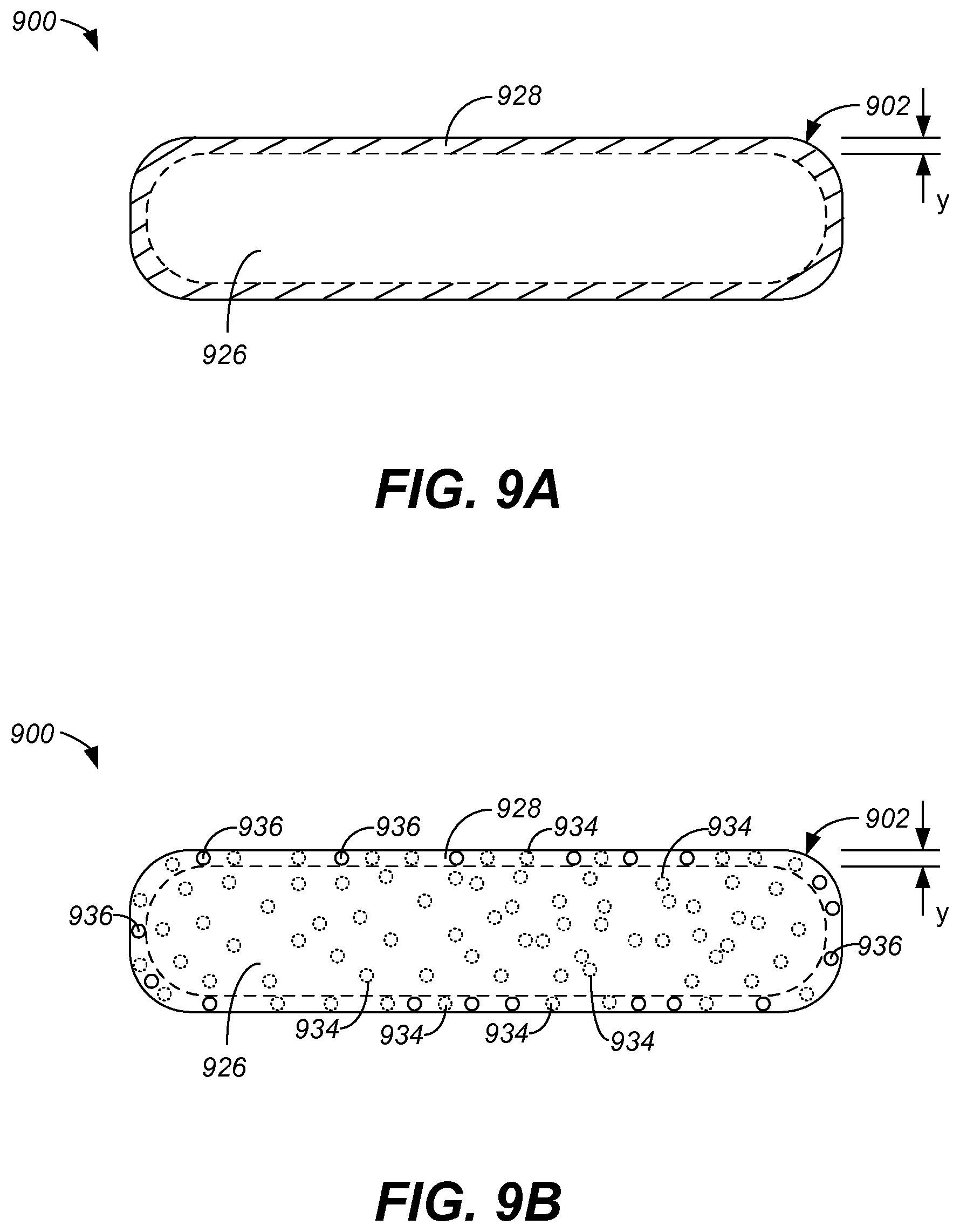
FIG. 9A is a cross-sectional diagram of a glass cover which has been chemically treated such that a chemically strengthened layer is created according to one embodiment.
FIG. 9B is a cross-sectional diagram of a glass cover which has been chemically treated, as shown to include a chemically treated portion in which potassium ions have been implanted according to one embodiment.
FIG. 10 is a diagrammatic representation of a chemical treatment process that involves submerging a glass cover in an ion bath according to one embodiment.
FIGS. 11A and 11B are diagrammatic representations of electronic device according to one embodiment.
FIGS. 12A and 12B are diagrammatic representations of electronic device according to another embodiment.
DETAILED DESCRIPTION OF EMBODIMENTS OF THE INVENTION
The invention relates generally to increasing the strength of glass. The use of multi-bath chemical processing for a glass article can facilitate controlled chemical strengthening. Through multi-bath (or multi-step) chemical processing, differing levels of strengthening can be achieved for different portion of glass articles. The multi-bath chemical processing can be achieved through the use of successive chemical baths. Accordingly, glass articles that have undergone multi-bath chemical processing are able to be not only thin but also sufficiently strong and resistant to damage. The strengthened glass articles are well suited for use in consumer products, such as consumer electronic devices (e.g., portable electronic devices).
Embodiments of the invention can relate to apparatus, systems and methods for improving strength of a thin glass member for a consumer product, such as a consumer electronic device. In one embodiment, the glass member may be an outer surface of a consumer electronic device. For example, the glass member may, for example, correspond to a glass cover that helps form part of a display area of the electronic device (i.e., situated in front of a display either as a separate part or integrated within the display). As another example, the glass member may form a part of a housing for the consumer electronic device (e.g., may form an outer surface other than in the display area). In another embodiment, the glass member may be an inner component of a consumer electronic device. For example, the glass member can be a component glass piece of a LCD display provided internal to the housing of the consumer electronic device.
The apparatus, systems and methods for improving strength of thin glass are especially suitable for glass covers or displays (e.g., LCD displays), particularly those assembled in small form factor electronic devices such as handheld electronic devices (e.g., mobile phones, media players, personal digital assistants, remote controls, etc.). The glass can be thin in these small form factor embodiments, such as less than 3 mm, or more particularly between 0.3 and 2.5 mm. The apparatus, systems and methods can also be used for glass covers or displays for other devices including, but not limited to including, relatively larger form factor electronic devices (e.g., portable computers, tablet computers, displays, monitors, televisions, etc.). The glass can also be thin in these larger form factor embodiments, such as less than 5 mm, or more particularly between 0.3 and 3 mm.
Embodiments of the invention are discussed below with reference to FIGS. 1-12B. However, those skilled in the art will readily appreciate that the detailed description given herein with respect to these figures is for explanatory purposes as the invention extends beyond these limited embodiments. The illustrations provided in these figures are not necessarily drawn to scale; instead, the illustrations are presented in a manner to facilitate presentation.
FIG. 1 illustrates a glass strengthening system 100 according to one embodiment. The glass strengthening system 100 receives a glass article 102 to be strengthened through chemical processing. The glass article 102 is provided to a first bath station in which a first bath 104 is provided. The glass article 102 can be inserted (e.g., immersed) into the first bath 104 which includes a potassium solution 106. Next, the glass article 102 is removed from the first bath station and provided to a second bath station. The second bath station provides a second bath 108. The glass article can be inserted (e.g., immersed) into the second bath 108 which includes a potassium solution 110. Later, the glass article 102 is removed from the second bath 108. At this point, the glass article has been first enhanced and then strengthened. Through use of the multiple stages of chemical strengthening as well as masking portions of the glass article 102, the chemical strengthening can be controllably induced into the glass article 102.
Furthermore, following removal of the glass article from the second bath 108, post-processing can be performed on the glass article 102. Post-processing can vary widely dependent on intended application for the glass article. However, post-processing can, for example, include one or more of rinsing, polishing, annealing and the like.
The potassium solution 106 within the first bath 104 can be heated to a predetermined temperature, and the glass article 102 can be immersed within the first bath 104 for a predetermined period of time (duration). The degree of chemical strengthening of the glass article 102 is dependent on: (1) type of glass, (2) concentration of bath (e.g., K concentration), (3) time in the first bath 104, and (4) temperature of the first bath 104. Likewise, the potassium solution 110 within the second bath 108 can heated to a predetermined temperature, and the glass article 102 can be immersed within the second bath 108 for a predetermined period of time. The degree of chemically strengthening provided by the second bath 108 to the glass article is similarly dependent on: (1) type of glass, (2) concentration of bath (e.g., K concentration), (3) time in the second bath 108, and (4) temperature of the second bath 108.
In one implementation, the glass for the glass article 102 can, for example, be alumina silicate glass, soda lime glass or Lithium-based glass. Also, glass from different suppliers, even if the same type of glass, can have different properties and thus may require different values. In one embodiment the first bath 104 and the second bath 108 can be potassium nitrate (KNO3) baths. The time for the glass article 102 to remain immersed in the first bath 104 can, for example, be about 2-20 hours and the temperature for the first bath 104 can be about 350-450 degrees Celsius. The time for the glass article 102 to remain immersed in the second bath 108 can, for example, be about 2-20 hours and the temperature for the second bath 108 can be about 350-450 degrees Celsius. Also, an electronic field can be induced to assist with the chemical strengthening process, which would lower the duration of time the glass article 103 is to be immersed in an ion exchange bath and/or facilitate enhanced chemical strengthening.
FIG. 2 illustrates a glass article 200 according to one embodiment. The glass article 200 has a uniform thickness (t). Typically, the thickness for the glass article 200 depends on its usage. As an example, if the glass article 200 is destined for use as part of a portable electronic device, the thickness tends to be rather thin, such as on the order of 0.5 to 5.0 mm. The glass article 200 has an outer surface 202. When the glass article 200 is chemically strengthened, such as by placing the glass article 200 in a heated ion bath, ion exchange with other ions present at the outer surface 202 of the glass article. Accordingly, during the chemical strengthening, the ion exchange can be controlled to occur to a determined depth of layer (DoL). The result is an outer strengthened region 204 of the glass article 200. The amount of chemical strengthening and the depth of the depth of layer (DoL) depends on various criteria including thickness of the glass article 200, intended usage of the glass article 200, type of glass, concentration of the ion bath, temperature of the ion bath, and others. As an example, the depth of layer could range from 10-200 .mu.m.
FIG. 3 illustrates a glass article 300 according to another embodiment. The glass article 300 has an outer surface 302 and a variable thickness. Unlike FIG. 2, the glass article 300 has a variable thickness. In particular, the glass article 300 can include side regions 304 and a middle region 306. In the example illustrated in FIG. 3, the middle region 306 has a thickness that is substantially different from a thickness (t) of the side regions 304. For example, the thickness of the middle region 306 can be 20-70% of the thickness (t) of the side regions 304. Typically, the thickness (t) for the glass article 300 depends on its usage. As an example, if the glass article 300 is destined for use as part of a portable electronic device, the thickness tends to be rather thin, such as on the order of 0.3 to 2.0 mm.
Nevertheless, if the glass article 300 is chemically strengthened by placing the glass article 300 in a heated ion bath, ion exchange with other ions at the surface 302 of the glass article can occur. The ion exchange occurs to pay determined depth of layer (DL L). Hence, similar to FIG. 2, the chemical strengthening serves to strengthen an outer peripheral region 308 of the glass article 300. In this embodiment, the depth of layer (DoL) is generally uniform across the outer periphery of the glass article 300. However, since the middle region 306 has a smaller thickness than do the side regions 304, the depth of layer can be restricted so that the middle region 306 (which is the thinner region) is not placed under too much central tension. Consequently, with respect to the glass article 300, if chemical strengthening is performed in a uniform fashion such as illustrated in FIG. 3, the depth of layer for such chemical strengthening may be unduly limited or not optimized.
FIG. 4 is a cross-sectional diagram of a glass article 400 according to still another embodiment. The glass article 400 illustrated in FIG. 4 has an outer surface 402. The glass article 400 has a variable thickness in which side regions 404 are thicker than an inner region 406. In the example illustrated in FIG. 4, the middle region 406 has a thickness that is substantially different from a thickness (t) of the side regions 404. For example, the thickness of the middle region 406 can be 20-70% of the thickness (t) of the side regions 404. Typically, the thickness (t) for the glass article 400 depends on its usage. As an example, if the glass article 400 is destined for use as part of a portable electronic device, the thickness tends to be rather thin, such as on the order of 0.5 to 5.0 mm.
Through chemical strengthening, the glass article 400 can be rendered stronger. Given that the glass article 400 has a variable thickness, the chemical strengthening provided to the different regions can be separately controlled. For example, the chemical strengthening for the different regions can be optimized for it features, characteristics or usage.
In the embodiment illustrated in FIG. 4, the side regions 404 which are thicker than the middle region 406 can be chemically strengthened to a greater extent than the middle region 406. Specifically, as depicted in FIG. 4, the side regions 404 show that a chemical strengthened region 408 is provided to a first depth of layer (DoL-1), and the middle region 406 shows that a chemical strengthened region 410 has a second depth of layer (DoL-2). As clearly depicted in FIG. 4, the first depth of layer (DoL-1) is greater than the second depth of layer (DoL-2). Since the side regions 404 are thicker regions of the glass article 400, greater amounts of chemical strengthening can be safely provided to the side regions 404. For the middle portion 406, chemical strengthening can be performed, but due to its relative thinness, the amount, level or degree of chemical strengthening can be less than that of the side regions 404.
In one embodiment, the ability to separately control the amount of chemical strengthening provided to different regions of glass article, allows chemical strengthening to be optimized on a per region basis. Consequently, a glass article having variable thickness can be chemically strengthened in a manner that optimizes chemical strengthening for each of the distinct regions.
FIG. 5 is a flow diagram of a glass strengthening process 500 according to one embodiment. The glass strengthening process 500 is particularly well-suited for strengthening a glass article that has regions of different thickness. For example, the glass strengthening process 500 can yield the glass article 400 shown in FIG. 4 which has different degree, amount or level of chemically strengthening applied to different regions.
The glass strengthening process 500 can initially obtain 502 a glass article that is to be strengthened. The glass article can be configured to have a first region with a first thickness and a second region with a second thickness. In other words, the glass article can be considered to have variable thickness.
After the glass article is obtained 502, a first mask can be applied 504 to the second region of the glass article. The glass article can then be chemically strengthened 506. More particularly, the first region of the glass article can be chemically strengthened 506, while the second region is not chemically strengthened. The first mask can serves to inhibit chemical strengthening from being performed with respect to the second region. After the chemical strengthening 506 has concluded, the first mask can be removed 508 from the second region. Then, a second mask can be applied 510 to the first region of the glass article. The second mask can serve to inhibit chemical strengthening from being performed with respect to the first region.
After the second mask has been applied 510, the glass article can again be chemically strengthened 512. At this point, the second region of the glass article is being chemically strengthened 512, while the second mask serves to prevent additional chemical strengthening to the first region of the class article. After the chemical strengthening 512 has concluded, the second mask can be removed 514 from the first region. Following the removal 514 of the second mask from the first region, the glass strengthening process 500 can end.
Additionally, although not shown, additional post-processing can be performed with respect to the glass member. Still further, the glass article can eventually be used in a consumer electronic device, such as a handheld electronic device where the glass article can form, for example, a portion of said outer housing.
Although the first mask and the second mask can be formed such that chemically strengthening is completely blocked by the mask material, it should be understood that the mask material might only reduce chemical strengthening. The masking material can vary, including a metal layer (e.g., foil), polyimide, and the like. Photolithographic patterning or etching can be used to pattern the mask material. The metal layer can, for example, be aluminum.
FIGS. 6A-6F illustrate processing to chemically strengthened a glass article 600. The processing can correspond to the glass strengthening process 500 illustrated in FIG. 5. In FIG. 6A, the glass article 600 is shown having a variable thickness. The glass article 600 has a thick region 602 with a thickness t1, and a thin region 604 having a thickness t2. In FIG. 6B, a mask 606 can then be applied over the thin region 604 of the glass article 600. Then, as illustrated in FIG. 6C, upon placing the glass article 600 with the applied mask 606 into a chemical strengthening bath, a peripheral region 608 of the thick region 602 can be chemically strengthened. The chemical strengthening at the peripheral region 608 has a controlled first depth of layer. Following the chemical strengthening that results in the peripheral region 608 of the thick region 602, the glass article 600 can be removed from the chemical strengthening bath and the mask 606 can be removed. In FIG. 6D, a second mask 610 can be applied to the thick region 602 of the glass article 600. Then, as illustrated in FIG. 6E, upon placing the glass article 600 with the applied second mask 610 into a chemical strengthening bath (which can be the same as the above-described chemical strengthening bath or a new chemical strengthening bath) so that a peripheral region 612 of the thin region 604 can be chemically strengthened. The chemical strengthening of the peripheral region 612 has a second depth of layer. In this example, the second depth of layer is less than the first depth of layer. Following the chemical strengthening that results in the peripheral region 612 of the thin region 604, the glass article 600 can be removed from the chemical strengthening bath and the mask 610 can be removed. Consequently, as shown in FIG. 6F, the resulting glass article 600' represents a strengthened version of the glass article 600 in which the thick region 602 is chemically strengthened to a greater extent than the thin region 604. Advantageously, the different regions of the glass article 600 are able to be chemically strengthened differently for better performance.
Following such chemical strengthening, depending on the type of glass, the glass article 600' having a 1 mm thickness can have a central tension (CT) of about 20-100 MPa (Mega Pascals) at a central portion, the peripheral portion 612 can have a peak compressive stress at the surface 602 of about 300-1100 MPa, and the depth of the compressive layer (i.e., depth of layer) can be about 20-150 microns. As examples, the glass article 600' can be formed of aluminosilicate glass or lithium-aluminosilicate glass. In a more specific embodiment, the glass article 600' having a 1 mm thickness can have a central tension (CT) of about 50-60 MPa (Mega Pascals) at a central portion, the peripheral portion 612 can have a peak compressive stress at the surface 602 of about 700-800 MPa, and the depth of the compressive layer (i.e., depth of layer) can be about 50-60 microns for the thick region 602 and about 30-40 microns for the thin region 604.
FIG. 7 is a flow diagram of a glass strengthening process 700 according to another embodiment. The glass strengthening process 700 can initially obtain 702 a glass article to be chemically strengthened.
The glass strengthening process 700 is particularly well-suited for strengthening a glass article that has regions of different thickness. For example, the glass strengthening process 700 can yield the glass article 400 shown in FIG. 4 which has different degree, amount or level of chemically strengthening applied to different regions.
In this embodiment, the glass article has at least a plurality of distinct regions, with one of the regions corresponding to a thinner region and another of the regions corresponding to a sticker region. Once the glass article has been obtained 702, a mask can be applied 704 to the thinner region. Next, the thicker region of the glass article can be chemically strengthened 706. At this point, the mask that has been applied 704 to the thinner region of the glass article serves to inhibit chemical strengthening of the thinner region. After the chemical strengthening 706 of the thicker region has concluded, the mask can be removed 708 from the thinner region. Thereafter, the glass article, including both the thinner region and the thicker region, can be chemically strengthened 710. Following the chemical strengthening 710, the glass strengthening process 700 can end.
Additionally, although not shown, additional post-processing can be performed with respect to the glass member. Still further, the glass article can eventually be used in a consumer electronic device, such as a handheld electronic device where the glass article can form, for example, a portion of said outer housing.
Although the mask applied 704 to the thinner region can be formed such that chemically strengthening is completely blocked by the mask material. Alternatively, the mask applied 704 to the thicker region can partially block chemical strengthening. The masking material can vary, including a metal layer (e.g., foil), polyimide, and the like. Photolithographic patterning or etching can be used to pattern the mask material. The metal layer can, for example, be aluminum.
FIGS. 8A-8E illustrate processing to chemically strengthened a glass article 800. The processing can correspond to the glass strengthening process 700 illustrated in FIG. 7. In FIG. 8A, the glass article 800 is shown having a variable thickness. The glass article 800 has a thick region 802 with a thickness t1, and a thin region 804 having a thickness t2. In FIG. 8B, a mask 806 can then be applied over the thin region 804 of the glass article 800. Then, as illustrated in FIG. 8C, upon placing the glass article 800 with the applied mask 806 into a chemical strengthening bath, a peripheral region 808 of the thick region 802 can be chemically strengthened. The chemical strengthening at the peripheral region 808 has a controlled first depth of layer (DoL-1). Following the chemical strengthening that results in the peripheral region 808 of the thick region 802, the glass article 800 can be removed from the chemical strengthening bath and the mask 806 can be removed. FIG. 8C illustrates the glass article 800 after the chemical strengthening and removal of the mask 806.
Then, as illustrated in FIG. 8E, upon placing the glass article 800 (with no mask applied) into a chemical strengthening bath (which can be the same as the above-described chemical strengthening bath or a new chemical strengthening bath) so that a peripheral region 808 of the thick region 802 as well as a peripheral region 810 of the thin region 804 can be chemically strengthened. The chemical strengthening of the peripheral region 810 following the subsequent chemical strengthening has a second depth of layer (DoL-2). Additionally, the chemical strengthening of the peripheral region 808 can provide further chemical strengthening to the peripheral region 808 of the thick region 802. The chemical strengthening of the peripheral region 808 following the subsequent chemical strengthening has a third depth of layer (DoL-3). In this example, the second depth of layer is less than the third depth of layer. Following the subsequent chemical strengthening that results in the peripheral region 810 of the thin region 804 as well as in the peripheral region 808 of the thick region 802, the glass article 800 can be removed from the chemical strengthening bath. Consequently, as shown in FIG. 8E, the resulting glass article 800' represents a strengthened version of the glass article 800 in which the thick region 802 is chemically strengthened to a greater extent than the thin region 804. Advantageously, the different regions of the glass article 800 are able to be chemically strengthened differently for better performance.
Following such chemical strengthening, depending on the type of glass, the glass article 800' having a 1 mm thickness can have a central tension (CT) of about 20-100 MPa (Mega Pascals) at a central portion, the peripheral portion 808 can have a peak compressive stress at its surface of about 300-1100 MPa, and the depth of the compressive layer (i.e., depth of layer) can be about 20-150 microns. As examples, the glass article 800' can be formed of aluminosilicate glass or lithium-aluminosilicate glass. In a more specific embodiment, the glass article 800' having a 1 mm thickness can have a central tension (CT) of about 50-60 MPa (Mega Pascals) at a central portion, the peripheral portion 808 can have a peak compressive stress at the surface of about 700-800 MPa, and the depth of the compressive layer (i.e., depth of layer) can be about 50-60 microns for the thick region 802 and about 30-40 microns for the thin region 804.
A glass cover which has undergone a chemical strengthening process generally includes a chemically strengthened layer, as previously mentioned. FIG. 9A is a cross-sectional diagram of a glass cover which has been chemically treated such that a chemically strengthened layer is created according to one embodiment. A glass cover 900 includes a chemically strengthened layer 928 and a non-chemically strengthened portion 926. Although the glass cover 900 is, in one embodiment, subjected to chemical strengthening as a whole, the outer surfaces receive the strengthening. The effect of the strengthening is that the non-chemically strengthened portion 926 is in tension, while the chemically strengthened layer 928 is in compression. While glass cover 900 in FIG. 9A is shown as having a rounded edge geometry 902, it should be appreciated that glass cover 900 may generally have any edge geometry, though rounded geometries at edges may allow for increased strengthening of the edges of glass cover 900. Rounded edge geometry 902 is depicted by way of example, and not for purposes of limitation.
FIG. 9B is a cross-sectional diagram of a glass cover which has been chemically treated, as shown to include a chemically treated portion in which potassium ions have been implanted according to one embodiment. Chemically strengthened layer 928 has a thickness (y) which may vary depending upon the requirements of a particular system in which glass cover 900 is to be utilized. Non-chemically strengthened portion 926 generally includes Na.sup.+ ions 934 but no Alkali metal ions 936. A chemical strengthening process causes chemically strengthened layer 928 to be formed such that chemically strengthened layer 928 includes both Na.sup.+ ions 934 and Alkali metal ions 936.
FIG. 10 is a diagrammatic representation of a chemical treatment process that involves submerging a glass cover in an ion bath according to one embodiment. When glass cover 1000, which is partially shown in cross-section, is submerged or soaked in a heated ion bath 1032, diffusion occurs. As shown, Alkali metal ions 1034 (e.g., Sodium (Na)) which are present in glass cover 1000 diffuse into ion bath 1032 while Alkali metal ions 1036 (e.g., potassium (K)) in ion bath 1032 diffuse into glass cover 1000, such that a chemically strengthened layer 1028 is formed. In other words, Alkali metal ions 1036 from ion bath 1032 can be exchanged with Na.sup.+ ions 1034 to form chemically strengthened layer 1028. Alkali metal ions 1036 typically would not diffuse into a center portion 1026 of glass cover 1000. By controlling the duration (i.e., time) of a chemical strengthening treatment, temperature and/or the concentration of Alkali metal ions 1036 in ion bath 1032, the thickness (y) of chemically strengthened layer 1028 may be substantially controlled.
The concentration of Alkali metal ions in an ion bath may be varied while a glass cover is soaking in the ion bath. In other words, the concentration of Alkali metal ions in an ion bath may be maintained substantially constant, may be increased, and/or may be decreased while a glass cover is submerged in the ion bath without departing from the spirit or the scope of the present invention. For example, as Alkali metal ions displace Na.sup.+ ions in the glass, the Na.sup.+ ions become part of the ion bath. Hence, the concentration of Alkali metal ions in the ion bath may change unless additional Alkali metal ions are added into the ion bath.
As previously discussed, glass covers can be used as an outer surface of portions of a housing for electronic devices, such as portable electronic devices. Those portable electronic devices that are small and highly portable can be referred to as handheld electronic devices. A handheld electronic device may, for example, function as a media player, phone, internet browser, email unit or some combination of two or more of such. A handheld electronic device generally includes a housing and a display area.
FIGS. 11A and 11B are diagrammatic representations of electronic device 1100 according to one embodiment. FIG. 11A illustrates a top view for the electronic device 1100, and FIG. 11B illustrates a cross-sectional side view for electronic device 1100 with respect to reference line A-A'. Electronic device 1100 can include housing 1102 that has glass cover window 1104 (glass cover) as a top surface. Cover window 1104 is primarily transparent so that display assembly 1106 is visible through cover window 1104. Cover window 1104 can be chemically strengthened using the multi-bath chemical processing described herein. Display assembly 1106 can, for example, be positioned adjacent cover window 1104. Housing 1102 can also contain internal electrical components besides the display assembly, such as a controller (processor), memory, communications circuitry, etc. Display assembly 1106 can, for example, include a LCD module. By way of example, display assembly 1106 may include a Liquid Crystal Display (LCD) that includes a Liquid Crystal Module (LCM). In one embodiment, cover window 1104 can be integrally formed with the LCM. Housing 1102 can also include an opening 1108 for containing the internal electrical components to provide electronic device 1100 with electronic capabilities. In one embodiment, housing 1102 need not include a bezel for cover window 1104. Instead, cover window 1104 can extend across the top surface of housing 1102 such that the edges of cover window 1104 can be aligned (or substantially aligned) with the sides of housing 1102. The edges of cover window 1104 can remain exposed. Although the edges of cover window 1104 can be exposed as shown in FIGS. 11A and 11B, in alternative embodiment, the edges can be further protected. As one example, the edges of cover window 1104 can be recessed (horizontally or vertically) from the outer sides of housing 1102. As another example, the edges of cover window 1104 can be protected by additional material placed around or adjacent the edges of cover window 1104.
Cover window 1104 may generally be arranged or embodied in a variety of ways. By way of example, cover window 1104 may be configured as a protective glass piece that is positioned over an underlying display (e.g., display assembly 1106) such as a flat panel display (e.g., LCD) or touch screen display (e.g., LCD and a touch layer). Alternatively, cover window 1104 may effectively be integrated with a display, i.e., glass window may be formed as at least a portion of a display. Additionally, cover window 1104 may be substantially integrated with a touch sensing device such as a touch layer associated with a touch screen. In some cases, cover window 1104 can serve as the outer most layer of the display.
FIGS. 12A and 12B are diagrammatic representations of electronic device 1200 according to another embodiment. FIG. 12A illustrates a top view for electronic device 1200, and FIG. 12B illustrates a cross-sectional side view for electronic device 1200 with respect to reference line B-B'. Electronic device 1200 can include housing 1202 that has glass cover window 1204 (glass cover) as a top surface. In this embodiment, cover window 1204 can be protected by side surfaces 1203 of housing 1202. Here, cover window 1204 does not fully extend across the top surface of housing 1202; however, the top surface of side surfaces 1203 can be adjacent to and aligned vertically with the outer surface of cover window 1204. Since the edges of cover window 1204 can be rounded for enhanced strength, there may be gaps 1205 that are present between side surfaces 1203 and the peripheral edges of cover window 1204. Gaps 1205 are typically very small given that the thickness of cover window 1204 is thin (e.g., less than 3 mm). However, if desired, gaps 1205 can be filled by a material. The material can be plastic, rubber, metal, etc. The material can conform in gap 1205 to render the entire front surface of electronic device 1200 flush, even across gaps 1205 proximate the peripheral edges of cover window 1204. The material filling gaps 1205 can be compliant. The material placed in gaps 1205 can implement a gasket. By filling the gaps 1205, otherwise probably undesired gaps in the housing 1202 can be filled or sealed to prevent contamination (e.g., dirt, water) forming in the gaps 1205. Although side surfaces 1203 can be integral with housing 1202, side surface 1203 could alternatively be separate from housing 1202 and, for example, operate as a bezel for cover window 1204.
Cover window 1204 is primarily transparent so that display assembly 1206 is visible through cover window 1204. Display assembly 1206 can, for example, be positioned adjacent cover window 1204. Housing 1202 can also contain internal electrical components besides the display assembly, such as a controller (processor), memory, communications circuitry, etc. Display assembly 1206 can, for example, include a LCD module. By way of example, display assembly 1206 may include a Liquid Crystal Display (LCD) that includes a Liquid Crystal Module (LCM). In one embodiment, cover window 1204 is integrally formed with the LCM. Housing 1202 can also include an opening 1208 for containing the internal electrical components to provide electronic device 1200 with electronic capabilities.
The front surface of electronic device 1200 can also include user interface control 1208 (e.g., click wheel control). In this embodiment, cover window 1204 does not cover the entire front surface of electronic device 1200. Electronic device 1200 essentially includes a partial display area that covers a portion of the front surface.
Cover window 1204 may generally be arranged or embodied in a variety of ways. By way of example, cover window 1204 may be configured as a protective glass piece that is positioned over an underlying display (e.g., display assembly 1206) such as a flat panel display (e.g., LCD) or touch screen display (e.g., LCD and a touch layer). Alternatively, cover window 1204 may effectively be integrated with a display, i.e., glass window may be formed as at least a portion of a display. Additionally, cover window 1204 may be substantially integrated with a touch sensing device such as a touch layer associated with a touch screen. In some cases, cover window 1204 can serve as the outer most layer of the display.
As noted above, the electronic device can be a handheld electronic device or a portable electronic device. The invention can serve to enable a glass cover to be not only thin but also adequately strong. Since handheld electronic devices and portable electronic devices are mobile, they are potentially subjected to various different impact events and stresses that stationary devices are not subjected to. As such, the invention is well suited for implementation of glass surfaces for handheld electronic device or a portable electronic device that are designed to be thin.
The strengthened glass, e.g., glass covers or cover windows, is particularly useful for thin glass applications. For example, the thickness of a glass cover being strengthened can be between about 0.5-2.5 mm. In other embodiments, the strengthening is suitable for glass products whose thickness is less than about 2 mm, or even thinner than about 1 mm, or still even thinner than about 0.6 mm.
Chemically strengthening glass, e.g., glass covers or cover windows, can be more effective for edges of glass that are rounded by a predetermined edge geometry having a predetermined curvature (or edge radius) of at least 10% of the thickness applied to the corners of the edges of the glass. In other embodiments, the predetermined curvature can be between 20% to 50% of the thickness of the glass. A predetermined curvature of 50% can also be considered a continuous curvature, one example of which is illustrated in FIG. 3E.
In one embodiment, the size of the glass cover depends on the size of the associated electronic device. For example, with handheld electronic devices, the size of the glass cover is often not more than five (5) inches (about 12.7 cm) diagonal. As another example, for portable electronic devices, such as smaller portable computers or tablet computers, the size of the glass cover is often between four (4) (about 10.2 cm) to twelve (12) inches (about 30.5 cm) diagonal. As still another example, for portable electronic devices, such as full size portable computers, displays (including televisions) or monitors, the size of the glass cover is often between ten (10) (about 25.4 cm) to twenty (20) inches (about 50.8 cm) diagonal or even larger.
However, it should be appreciated that with larger screen sizes, the thickness of the glass layers may need to be greater. The thickness of the glass layers may need to be increased to maintain planarity of the larger glass layers. While the displays can still remain relatively thin, the minimum thickness can increase with increasing screen size. For example, the minimum thickness of the glass cover can correspond to about 0.3 mm for small handheld electronic devices, about 0.5 mm for smaller portable computers or tablet computers, about 1.0 mm or more for full size portable computers, displays or monitors, again depending on the size of the screen. However, more generally, the thickness of the glass cover can depend on the application and/or the size of electronic device.
As discussed above, glass cover or, more generally, a glass piece may be chemically treated such that surfaces of the glass are effectively strengthened. Through such strengthening, glass pieces can be made stronger so that thinner glass pieces can be used with consumer electronic device. Thinner glass with sufficient strength allows for consumer electronic device to become thinner.
The techniques describe herein may be applied to glass surfaces used by any of a variety of electronic devices including but not limited handheld electronic devices, portable electronic devices and substantially stationary electronic devices. Examples of these include any known consumer electronic device that includes a display. By way of example, and not by way of limitation, the electronic device may correspond to media players, mobile phones (e.g., cellular phones), PDAs, remote controls, notebooks, tablet PCs, monitors, all in one computers and the like.
The various aspects, features, embodiments or implementations of the invention described above can be used alone or in various combinations.
Additional details on strengthening edges of glass articles and/or different chemical baths can be found in: (i) U.S. Provisional Patent Application No. 61/156,803, filed Mar. 2, 2009 and entitled "TECHNIQUES FOR STRENGTHENING GLASS COVERS FOR PORTABLE ELECTRONIC DEVICES", which is herein incorporated by reference; (ii) International Patent Application No. PCT/US2010/025979, filed Mar. 2, 2010 and entitled "Techniques for Strengthening Glass Covers for Portable Electronic Devices", which is herein incorporated by reference; (iii) U.S. Provisional Patent Application No. 61/374,988, filed Aug. 18, 2010, and entitled "ENHANCED STRENGTHING OF GLASS", which is hereby incorporated herein by reference; (iv) U.S. patent application Ser. No. 12/895,823, filed Sep. 30, 2010 and entitled "ENHANCED STRENGTHENING OF GLASS"; (v) U.S. patent application Ser. No. 12/895,372, filed Sep. 30, 2010 and entitled "TECHNIQUES FOR STRENGTHENING GLASS COVERS FOR PORTABLE ELECTRONIC DEVICES", which is herein incorporated by reference; (vi) U.S. patent application Ser. No. 12/895,393, filed Sep. 30, 2010 and entitled "TECHNIQUES FOR STRENGTHENING GLASS COVERS FOR PORTABLE ELECTRONIC DEVICES", which is herein incorporated by reference; (vii) U.S. Provisional Patent Application No. 61/301,585, filed Feb. 4, 2010 and entitled "TECHNIQUES FOR STRENGTHENING GLASS COVERS FOR PORTABLE ELECTRONIC DEVICES," which is hereby incorporated herein by reference; (viii) U.S. Provisional Patent Application No. 61/410,290, filed Nov. 4, 2010, and entitled "ENHANCED STRENGTHING OF GLASS", which is hereby incorporated herein by reference; (ix) PCT International Application No. PCT/US2011/023499, filed Feb. 2, 2011, and entitled "ENHANCED CHEMICAL STRENGTHENING GLASS OF COVERS FOR PORTABLE ELECTRONIC DEVICES", which is hereby incorporated herein by reference; (x) U.S. patent application Ser. No. 12/847,926, filed Jul. 30, 2010, and entitled "ELECTRONIC DEVICE HAVING SELECTIVELY STRENGTHENING GLASS COVER GLASS", which is hereby incorporated herein by reference; (xi) U.S. Provisional Patent Application No. 61/453,404, filed Mar. 16, 2011, and entitled "ELECTRONIC DEVICE HAVING SELECTIVELY STRENGTHENED GLASS", which is hereby incorporated herein by reference; (xii) U.S. patent application Ser. No. 13/235,090, filed concurrently, and entitled "ELECTRONIC DEVICE HAVING SELECTIVELY STRENGTHENED GLASS", which is hereby incorporated herein by reference.
Although only a few embodiments of the invention have been described, it should be understood that the invention may be embodied in many other specific forms without departing from the spirit or the scope of the present invention. By way of example, the steps associated with the methods of the invention may vary widely. Steps may be added, removed, altered, combined, and reordered without departing from the spirit of the scope of the invention. Similarly, while operations are depicted in the drawings in a particular order, this should not be understood as requiring that such operations be performed in the particular order shown or in sequential order, or that all illustrated operations be performed, to achieve desirable results.
While this specification contains many specifics, these should not be construed as limitations on the scope of the disclosure or of what may be claimed, but rather as descriptions of features specific to particular embodiment of the disclosure. Certain features that are described in the context of separate embodiments can also be implemented in combination. Conversely, various features that are described in the context of a single embodiment can also be implemented in multiple embodiments separately or in any suitable subcombination. Moreover, although features may be described above as acting in certain combinations, one or more features from a claimed combination can in some cases be excised from the combination, and the claimed combination may be directed to a subcombination or variation of a subcombination.
While this invention has been described in terms of several embodiments, there are alterations, permutations, and equivalents, which fall within the scope of this invention. It should also be noted that there are many alternative ways of implementing the methods and apparatuses of the present invention. It is therefore intended that the following appended claims be interpreted as including all such alterations, permutations, and equivalents as fall within the true spirit and scope of the present invention.
* * * * *
References
D00000
D00001
D00002
D00003
D00004
D00005
D00006
D00007
D00008
D00009
D00010
XML
uspto.report is an independent third-party trademark research tool that is not affiliated, endorsed, or sponsored by the United States Patent and Trademark Office (USPTO) or any other governmental organization. The information provided by uspto.report is based on publicly available data at the time of writing and is intended for informational purposes only.
While we strive to provide accurate and up-to-date information, we do not guarantee the accuracy, completeness, reliability, or suitability of the information displayed on this site. The use of this site is at your own risk. Any reliance you place on such information is therefore strictly at your own risk.
All official trademark data, including owner information, should be verified by visiting the official USPTO website at www.uspto.gov. This site is not intended to replace professional legal advice and should not be used as a substitute for consulting with a legal professional who is knowledgeable about trademark law.