Automatically assessing an anatomical surface feature and securely managing information related to the same
Fairbairn , et al. Sept
U.S. patent number 10,777,317 [Application Number 15/974,433] was granted by the patent office on 2020-09-15 for automatically assessing an anatomical surface feature and securely managing information related to the same. This patent grant is currently assigned to ARANZ Healthcare Limited. The grantee listed for this patent is ARANZ Healthcare Limited. Invention is credited to Michael David John Bryce, Bruce Leslie Keith Davey, Christopher Keith Fairbairn, Mark Arthur Nixon, Brent Stephen Robinson.


View All Diagrams
| United States Patent | 10,777,317 |
| Fairbairn , et al. | September 15, 2020 |
Automatically assessing an anatomical surface feature and securely managing information related to the same
Abstract
A facility for procuring and analyzing information about an anatomical surface feature from a caregiver that is usable to generate an assessment of the surface feature is described. The facility displays information about the surface feature used in the assessment of the surface feature. The facility obtains user input and/or data generated by an image capture device to assess the surface feature or update an existing assessment of the surface feature.
| Inventors: | Fairbairn; Christopher Keith (Christchurch, NZ), Bryce; Michael David John (Kaiapoi, NZ), Davey; Bruce Leslie Keith (Christchurch, NZ), Nixon; Mark Arthur (Christchurch, NZ), Robinson; Brent Stephen (Christchurch, NZ) | ||||||||||
|---|---|---|---|---|---|---|---|---|---|---|---|
| Applicant: |
|
||||||||||
| Assignee: | ARANZ Healthcare Limited
(Christchurch, NZ) |
||||||||||
| Family ID: | 1000005059862 | ||||||||||
| Appl. No.: | 15/974,433 | ||||||||||
| Filed: | May 8, 2018 |
Prior Publication Data
| Document Identifier | Publication Date | |
|---|---|---|
| US 20180254100 A1 | Sep 6, 2018 | |
Related U.S. Patent Documents
| Application Number | Filing Date | Patent Number | Issue Date | ||
|---|---|---|---|---|---|
| 15144722 | May 2, 2016 | 10013527 | |||
| Current U.S. Class: | 1/1 |
| Current CPC Class: | G16H 30/20 (20180101); H04N 1/00209 (20130101); G16H 15/00 (20180101); G06T 7/62 (20170101); H04N 1/00244 (20130101); H04N 7/185 (20130101); G16H 30/40 (20180101); G06T 7/0012 (20130101); H04N 13/204 (20180501); G06T 2207/10024 (20130101); G06T 2207/10012 (20130101); G06T 2207/10028 (20130101); G06T 2200/24 (20130101); G06T 2207/30004 (20130101); G06T 2207/20092 (20130101) |
| Current International Class: | G16H 30/40 (20180101); H04N 7/18 (20060101); H04N 1/00 (20060101); H04N 13/204 (20180101); G16H 15/00 (20180101); G06T 7/62 (20170101); G16H 30/20 (20180101); G06T 7/00 (20170101) |
References Cited [Referenced By]
U.S. Patent Documents
| 3259612 | July 1966 | Peter |
| 3335716 | August 1967 | Alt et al. |
| 4090501 | May 1978 | Chaitin |
| 4170987 | October 1979 | Anselmo et al. |
| 4236082 | November 1980 | Butler |
| 4505583 | March 1985 | Konomi |
| 4515165 | May 1985 | Carroll |
| 4535782 | August 1985 | Zoltan |
| 4556057 | December 1985 | Hiruma et al. |
| 4724480 | February 1988 | Hecker et al. |
| 4736739 | April 1988 | Flaton |
| 4768513 | September 1988 | Suzuki |
| 4773097 | September 1988 | Suzaki et al. |
| 4821117 | April 1989 | Sekiguchi |
| 4839807 | June 1989 | Doi et al. |
| 4851984 | July 1989 | Doi et al. |
| 4894547 | January 1990 | Leffell et al. |
| 4930516 | June 1990 | Alfano et al. |
| 4957114 | September 1990 | Zeng et al. |
| 4979815 | December 1990 | Tsikos |
| 4996994 | March 1991 | Steinhauer et al. |
| D315901 | April 1991 | Knowles |
| 5003977 | April 1991 | Suzuki et al. |
| 5016173 | May 1991 | Kenet et al. |
| 5036853 | August 1991 | Jeffcoat et al. |
| 5080100 | January 1992 | Trotel |
| 5157461 | October 1992 | Page |
| 5174297 | December 1992 | Daikuzono |
| 5241468 | August 1993 | Kenet |
| 5270168 | December 1993 | Grinnell |
| 5319550 | June 1994 | Griffith |
| 5363854 | November 1994 | Martens et al. |
| 5369496 | November 1994 | Alfano et al. |
| 5396331 | March 1995 | Kitoh et al. |
| 5408996 | April 1995 | Salb |
| 5421337 | June 1995 | Richards-Kortum et al. |
| 5515449 | May 1996 | Tsuruoka et al. |
| 5519208 | May 1996 | Esparza et al. |
| 5528703 | June 1996 | Lee |
| 5531520 | July 1996 | Grimson et al. |
| 5532824 | July 1996 | Harvey et al. |
| 5561526 | October 1996 | Huber et al. |
| 5588428 | December 1996 | Smith et al. |
| 5590660 | January 1997 | MacAulay et al. |
| 5603318 | February 1997 | Heilbrun et al. |
| 5627907 | May 1997 | Gur et al. |
| 5644141 | July 1997 | Hooker et al. |
| 5648915 | July 1997 | McKinney et al. |
| 5673300 | September 1997 | Reckwerdt et al. |
| 5689575 | November 1997 | Sako et al. |
| 5699798 | December 1997 | Hochman et al. |
| 5701902 | December 1997 | Vari et al. |
| 5717791 | February 1998 | Labaere et al. |
| D393068 | March 1998 | Kodama |
| 5740268 | April 1998 | Nishikawa et al. |
| 5749830 | May 1998 | Kaneko et al. |
| 5784162 | July 1998 | Cabib et al. |
| 5791346 | August 1998 | Craine et al. |
| 5799100 | August 1998 | Clarke et al. |
| 5810014 | September 1998 | Davis et al. |
| 5836872 | November 1998 | Kenet et al. |
| 5910972 | June 1999 | Ohkubo et al. |
| 5921937 | July 1999 | Davis et al. |
| 5946645 | August 1999 | Rioux et al. |
| 5957837 | September 1999 | Raab |
| 5967797 | October 1999 | Maldonado |
| 5967979 | October 1999 | Taylor et al. |
| 5969822 | October 1999 | Fright et al. |
| 5974165 | October 1999 | Giger et al. |
| 6032070 | February 2000 | Flock et al. |
| 6081612 | June 2000 | Gutkowicz-Krusin et al. |
| 6081739 | June 2000 | Lemchen |
| 6091995 | July 2000 | Ingle et al. |
| 6101408 | August 2000 | Craine et al. |
| 6208749 | March 2001 | Gutkowicz-Krusin et al. |
| 6215893 | April 2001 | Leshem et al. |
| 6265151 | July 2001 | Canter et al. |
| 6266453 | July 2001 | Hibbard et al. |
| 6272278 | August 2001 | Takahata et al. |
| 6278793 | August 2001 | Gur et al. |
| 6307957 | October 2001 | Gutkowicz-Krusin et al. |
| 6324417 | November 2001 | Cotton |
| D453350 | February 2002 | Fenton |
| 6359513 | March 2002 | Kuo et al. |
| 6359612 | March 2002 | Peter |
| D455166 | April 2002 | Raad |
| 6381026 | April 2002 | Schiff et al. |
| 6381488 | April 2002 | Dickey et al. |
| 6392744 | May 2002 | Holec |
| 6396270 | May 2002 | Smith |
| 6413212 | July 2002 | Raab |
| 6421463 | July 2002 | Poggio et al. |
| 6427022 | July 2002 | Craine et al. |
| 6491632 | December 2002 | Taylor |
| 6567682 | May 2003 | Osterweil et al. |
| 6594388 | July 2003 | Gindele et al. |
| 6594516 | July 2003 | Steckner et al. |
| 6603552 | August 2003 | Cline et al. |
| 6611617 | August 2003 | Crampton |
| 6611833 | August 2003 | Johnson |
| 6631286 | October 2003 | Pfeiffer et al. |
| 6648820 | November 2003 | Sarel |
| 6671349 | December 2003 | Griffith |
| 6678001 | January 2004 | Elberbaum |
| 6690964 | February 2004 | Bieger et al. |
| 6715675 | April 2004 | Rosenfeld |
| 6754370 | June 2004 | Hall-Holt et al. |
| 6770186 | August 2004 | Rosenfeld et al. |
| 6798571 | September 2004 | Wetzel et al. |
| 6809803 | October 2004 | O'Brien et al. |
| 6810279 | October 2004 | Mansfield et al. |
| 6816606 | November 2004 | Wetzel et al. |
| 6816847 | November 2004 | Toyama |
| 6862410 | March 2005 | Miyoshi |
| 6862542 | March 2005 | Lockhart et al. |
| 6873340 | March 2005 | Luby |
| 6873716 | March 2005 | Bowker |
| 6879394 | April 2005 | Amblard et al. |
| 6907193 | June 2005 | Kollias et al. |
| 6915073 | July 2005 | Seo |
| 6922523 | July 2005 | Merola et al. |
| 6941323 | September 2005 | Galperin |
| 6961517 | November 2005 | Merola et al. |
| 6968094 | November 2005 | Gallagher |
| 6993169 | January 2006 | Wetzel et al. |
| 7006223 | February 2006 | Mullani |
| 7013172 | March 2006 | Mansfield et al. |
| 7015906 | March 2006 | Olschewski et al. |
| 7027153 | April 2006 | Mullani |
| 7040536 | May 2006 | Rosenfeld |
| 7054674 | May 2006 | Cane et al. |
| 7064311 | June 2006 | Jung et al. |
| 7068828 | June 2006 | Kim et al. |
| 7068836 | June 2006 | Rubbert et al. |
| 7074509 | July 2006 | Rosenfeld et al. |
| 7103205 | September 2006 | Wang et al. |
| 7106885 | September 2006 | Osterweil et al. |
| 7127094 | October 2006 | Elbaum et al. |
| 7127280 | October 2006 | Dauga |
| 7128894 | October 2006 | Tannous et al. |
| 7130465 | October 2006 | Muenzenmayer et al. |
| 7136191 | November 2006 | Kaltenbach et al. |
| D533555 | December 2006 | Odhe et al. |
| 7155049 | December 2006 | Wetzel et al. |
| 7162063 | January 2007 | Craine et al. |
| 7167243 | January 2007 | Mullani |
| 7167244 | January 2007 | Mullani |
| 7181363 | February 2007 | Ratti et al. |
| 7194114 | March 2007 | Schneiderman |
| 7212660 | May 2007 | Wetzel et al. |
| 7227621 | June 2007 | Lee et al. |
| 7233693 | June 2007 | Momma |
| D547347 | July 2007 | Kim |
| 7248724 | July 2007 | Gutenev |
| D554682 | November 2007 | Martinez |
| 7295226 | November 2007 | Meron et al. |
| 7298881 | November 2007 | Giger et al. |
| D561804 | February 2008 | Asai |
| 7347365 | March 2008 | Rowe |
| 7376346 | May 2008 | Merola et al. |
| 7400754 | July 2008 | Jung et al. |
| 7421102 | September 2008 | Wetzel et al. |
| 7426319 | September 2008 | Takahashi |
| 7440597 | October 2008 | Rowe |
| 7450783 | November 2008 | Talapov et al. |
| 7460250 | December 2008 | Keightley et al. |
| 7474415 | January 2009 | Lin et al. |
| 7487063 | February 2009 | Tubic et al. |
| 7489799 | February 2009 | Nilsen et al. |
| 7495208 | February 2009 | Czarnek et al. |
| 7496399 | February 2009 | Maschke |
| 7509861 | March 2009 | Masotti et al. |
| 7538869 | May 2009 | Treado et al. |
| 7545963 | June 2009 | Rowe |
| D597205 | July 2009 | Koch |
| 7580590 | August 2009 | Lin et al. |
| 7581191 | August 2009 | Rice et al. |
| 7587618 | September 2009 | Inui et al. |
| 7595878 | September 2009 | Nelson et al. |
| D603441 | November 2009 | Wada |
| 7613335 | November 2009 | McLennan et al. |
| 7620211 | November 2009 | Browne et al. |
| 7647085 | January 2010 | Cane et al. |
| 7668350 | February 2010 | Rowe |
| 7684589 | March 2010 | Nilsen et al. |
| 7724379 | May 2010 | Kawasaki et al. |
| 7729747 | June 2010 | Stranc et al. |
| 7735729 | June 2010 | Rowe |
| 7738032 | June 2010 | Kollias et al. |
| 7751594 | July 2010 | Rowe et al. |
| 7765487 | July 2010 | Cable |
| 7819311 | October 2010 | Rowe et al. |
| 7869641 | January 2011 | Wetzel et al. |
| 7876948 | January 2011 | Wetzel et al. |
| 7881777 | February 2011 | Docherty et al. |
| 7894645 | February 2011 | Barsky |
| 7912320 | March 2011 | Minor |
| 7912534 | March 2011 | Grinvald et al. |
| 7916834 | March 2011 | Piorek et al. |
| 7931149 | April 2011 | Gilad et al. |
| 8000776 | August 2011 | Gono |
| 8019801 | September 2011 | Robb et al. |
| 8026942 | September 2011 | Payonk et al. |
| 8071242 | December 2011 | Rosenfeld et al. |
| 8078262 | December 2011 | Murphy et al. |
| 8094294 | January 2012 | Treado et al. |
| 8105233 | January 2012 | Abou El Kheir |
| D653687 | February 2012 | Yu |
| 8123704 | February 2012 | Richards |
| 8150500 | April 2012 | Goldman et al. |
| 8161826 | April 2012 | Taylor |
| 8165357 | April 2012 | Rowe |
| 8184873 | May 2012 | Rowe et al. |
| D662122 | June 2012 | Goodwin |
| 8213695 | July 2012 | Zouridakis |
| 8218873 | July 2012 | Boncyk et al. |
| 8218874 | July 2012 | Boncyk et al. |
| 8224077 | July 2012 | Boncyk et al. |
| 8224078 | July 2012 | Boncyk et al. |
| 8224079 | July 2012 | Boncyk et al. |
| 8229185 | July 2012 | Ennis et al. |
| 8238623 | August 2012 | Stephan et al. |
| 8306334 | November 2012 | Paschalakis et al. |
| 8326031 | December 2012 | Boncyk et al. |
| 8335351 | December 2012 | Boncyk et al. |
| 8437544 | May 2013 | Boncyk et al. |
| 8457395 | June 2013 | Boncyk et al. |
| 8463030 | June 2013 | Boncyk et al. |
| 8463031 | June 2013 | Boncyk et al. |
| 8467600 | June 2013 | Boncyk et al. |
| 8467602 | June 2013 | Boncyk et al. |
| 8478036 | July 2013 | Boncyk et al. |
| 8478037 | July 2013 | Boncyk et al. |
| 8480641 | July 2013 | Jacobs |
| 8488880 | July 2013 | Boncyk et al. |
| 8494264 | July 2013 | Boncyk et al. |
| 8520942 | August 2013 | Boncyk et al. |
| 8533879 | September 2013 | Taylor |
| 8548245 | October 2013 | Boncyk et al. |
| 8548278 | October 2013 | Boncyk et al. |
| 8582817 | November 2013 | Boncyk et al. |
| 8588476 | November 2013 | Spicola, Jr. |
| 8588527 | November 2013 | Boncyk et al. |
| D697210 | January 2014 | Delaney et al. |
| 8638986 | January 2014 | Jiang et al. |
| 8661915 | March 2014 | Taylor |
| 8712193 | April 2014 | Boncyk et al. |
| 8718410 | May 2014 | Boncyk et al. |
| 8734342 | May 2014 | Cable |
| 8755053 | June 2014 | Fright et al. |
| 8768052 | July 2014 | Kawano |
| 8774463 | July 2014 | Boncyk et al. |
| 8787621 | July 2014 | Spicola, Sr. et al. |
| 8787630 | July 2014 | Rowe |
| 8795169 | August 2014 | Cosentino et al. |
| 8798368 | August 2014 | Boncyk et al. |
| 8800386 | August 2014 | Taylor |
| 8814841 | August 2014 | Hartwell |
| 8824738 | September 2014 | Boncyk et al. |
| 8837868 | September 2014 | Boncyk et al. |
| 8842941 | September 2014 | Boncyk et al. |
| D714940 | October 2014 | Kim |
| 8855423 | October 2014 | Boncyk et al. |
| 8861859 | October 2014 | Boncyk et al. |
| 8867839 | October 2014 | Boncyk et al. |
| 8873891 | October 2014 | Boncyk et al. |
| 8875331 | November 2014 | Taylor |
| 8885983 | November 2014 | Boncyk et al. |
| 8892190 | November 2014 | Docherty et al. |
| 8904876 | December 2014 | Taylor et al. |
| 8913800 | December 2014 | Rowe |
| 8923563 | December 2014 | Boncyk et al. |
| 8938096 | January 2015 | Boncyk et al. |
| 8939918 | January 2015 | Richards |
| 8948459 | February 2015 | Boncyk et al. |
| 8948460 | February 2015 | Boncyk et al. |
| D724216 | March 2015 | Gant et al. |
| 8997588 | April 2015 | Taylor |
| 9014513 | April 2015 | Boncyk et al. |
| 9014514 | April 2015 | Boncyk et al. |
| 9014515 | April 2015 | Boncyk, et al. |
| 9020305 | April 2015 | Boncyk et al. |
| 9025813 | May 2015 | Boncyk et al. |
| 9025814 | May 2015 | Boncyk et al. |
| 9031278 | May 2015 | Boncyk et al. |
| 9036947 | May 2015 | Boncyk et al. |
| 9036948 | May 2015 | Boncyk et al. |
| 9041810 | May 2015 | Ecker et al. |
| 9110925 | August 2015 | Boncyk et al. |
| 9116920 | August 2015 | Boncyk et al. |
| 9135355 | September 2015 | Boncyk et al. |
| 9141714 | September 2015 | Boncyk et al. |
| 9148562 | September 2015 | Boncyk et al. |
| D740945 | October 2015 | Booth |
| 9154694 | October 2015 | Boncyk et al. |
| 9154695 | October 2015 | Boncyk et al. |
| 9167800 | October 2015 | Spicola, Jr. |
| 9179844 | November 2015 | Fright et al. |
| 9186053 | November 2015 | Viola |
| 9224205 | December 2015 | Tsin et al. |
| 9235600 | January 2016 | Boncyk et al. |
| 9244943 | January 2016 | Boncyk et al. |
| 9262440 | February 2016 | Boncyk et al. |
| 9288271 | March 2016 | Boncyk et al. |
| 9311540 | April 2016 | Ecker et al. |
| 9311552 | April 2016 | Boncyk et al. |
| 9311553 | April 2016 | Boncyk et al. |
| 9311554 | April 2016 | Boncyk et al. |
| 9317769 | April 2016 | Boncyk et al. |
| 9324004 | April 2016 | Boncyk et al. |
| 9330326 | May 2016 | Boncyk et al. |
| 9330327 | May 2016 | Boncyk et al. |
| 9330328 | May 2016 | Boncyk et al. |
| 9330453 | May 2016 | Soldatitsch et al. |
| 9342748 | May 2016 | Boncyk et al. |
| 9377295 | June 2016 | Fright et al. |
| 9395234 | July 2016 | Cosentino et al. |
| 9399676 | July 2016 | Schurpf et al. |
| 9438775 | September 2016 | Powers |
| 9451928 | September 2016 | Falco et al. |
| 9861285 | January 2018 | Fright et al. |
| 9955910 | May 2018 | Fright et al. |
| 2002/0054297 | May 2002 | Lee et al. |
| 2002/0149585 | October 2002 | Kacyra et al. |
| 2002/0197600 | December 2002 | Maione et al. |
| 2003/0004405 | January 2003 | Townsend et al. |
| 2003/0006770 | January 2003 | Smith |
| 2003/0031383 | February 2003 | Gooch |
| 2003/0036751 | February 2003 | Anderson et al. |
| 2003/0085908 | May 2003 | Luby |
| 2003/0164841 | September 2003 | Myers |
| 2003/0164875 | September 2003 | Myers |
| 2003/0229514 | December 2003 | Brown |
| 2003/0231793 | December 2003 | Crampton |
| 2004/0014165 | January 2004 | Keidar et al. |
| 2004/0059199 | March 2004 | Thomas et al. |
| 2004/0080497 | April 2004 | Enmei |
| 2004/0117343 | June 2004 | Johnson |
| 2004/0136579 | July 2004 | Gutenev |
| 2004/0146290 | July 2004 | Kollias et al. |
| 2004/0201694 | October 2004 | Gartstein et al. |
| 2004/0225222 | November 2004 | Zeng et al. |
| 2004/0264749 | December 2004 | Skladnev et al. |
| 2005/0012817 | January 2005 | Hampapur et al. |
| 2005/0027567 | February 2005 | Taha |
| 2005/0033142 | February 2005 | Madden et al. |
| 2005/0084176 | April 2005 | Talapov et al. |
| 2005/0094262 | May 2005 | Spediacci et al. |
| 2005/0111757 | May 2005 | Brackett et al. |
| 2005/0154276 | July 2005 | Barducci et al. |
| 2005/0190988 | September 2005 | Feron |
| 2005/0237384 | October 2005 | Jess et al. |
| 2005/0259281 | November 2005 | Boust |
| 2005/0273011 | December 2005 | Hattery et al. |
| 2005/0273267 | December 2005 | Maione |
| 2006/0008178 | January 2006 | Seeger et al. |
| 2006/0012802 | January 2006 | Shirley |
| 2006/0036135 | February 2006 | Kern |
| 2006/0036156 | February 2006 | Lachaine et al. |
| 2006/0044546 | March 2006 | Lewin et al. |
| 2006/0055943 | March 2006 | Kawasaki et al. |
| 2006/0058665 | March 2006 | Chapman |
| 2006/0072122 | April 2006 | Hu et al. |
| 2006/0073132 | April 2006 | Congote |
| 2006/0089553 | April 2006 | Cotton |
| 2006/0098876 | May 2006 | Buscema |
| 2006/0135953 | June 2006 | Kania et al. |
| 2006/0151601 | July 2006 | Rosenfeld |
| 2006/0204072 | September 2006 | Wetzel et al. |
| 2006/0210132 | September 2006 | Christiansen et al. |
| 2006/0222263 | October 2006 | Carlson |
| 2006/0268148 | November 2006 | Kollias et al. |
| 2006/0269125 | November 2006 | Kalevo et al. |
| 2006/0293613 | December 2006 | Fatehi et al. |
| 2007/0065009 | March 2007 | Ni et al. |
| 2007/0097381 | May 2007 | Tobiason et al. |
| 2007/0125390 | June 2007 | Afriat et al. |
| 2007/0129602 | June 2007 | Bettesh et al. |
| 2007/0229850 | October 2007 | Herber |
| 2007/0273894 | November 2007 | Johnson |
| 2007/0276195 | November 2007 | Xu et al. |
| 2007/0276309 | November 2007 | Xu et al. |
| 2008/0006282 | January 2008 | Sukovic |
| 2008/0021329 | January 2008 | Wood et al. |
| 2008/0045807 | February 2008 | Psota et al. |
| 2008/0088704 | April 2008 | Wendelken et al. |
| 2008/0098322 | April 2008 | Champion et al. |
| 2008/0126478 | May 2008 | Ferguson et al. |
| 2008/0165357 | July 2008 | Stem |
| 2008/0232679 | September 2008 | Hahn |
| 2008/0246759 | October 2008 | Summers |
| 2008/0275315 | November 2008 | Oka et al. |
| 2008/0285056 | November 2008 | Blayvas |
| 2008/0312642 | December 2008 | Kania et al. |
| 2008/0312643 | December 2008 | Kania et al. |
| 2009/0116712 | May 2009 | Al-Moosawi et al. |
| 2009/0118720 | May 2009 | Black et al. |
| 2009/0213213 | August 2009 | Fright et al. |
| 2009/0221874 | September 2009 | Vinther |
| 2009/0225333 | September 2009 | Bendall |
| 2009/0234313 | September 2009 | Mullejeans et al. |
| 2010/0004564 | January 2010 | Jendle |
| 2010/0020164 | January 2010 | Perrault |
| 2010/0091104 | April 2010 | Sprigle et al. |
| 2010/0111387 | May 2010 | Christiansen, II et al. |
| 2010/0121201 | May 2010 | Papaionnou |
| 2010/0149551 | June 2010 | Malinkevich |
| 2010/0156921 | June 2010 | McLennan et al. |
| 2010/0191126 | July 2010 | Al-Moosawi et al. |
| 2010/0278312 | November 2010 | Ortiz |
| 2011/0125028 | May 2011 | Wood et al. |
| 2011/0190637 | August 2011 | Knobel et al. |
| 2012/0035469 | February 2012 | Whelan et al. |
| 2012/0059266 | March 2012 | Davis et al. |
| 2012/0078088 | March 2012 | Whitestone et al. |
| 2012/0078113 | March 2012 | Whitestone et al. |
| 2012/0253200 | October 2012 | Stolka et al. |
| 2012/0265236 | October 2012 | Wesselmann |
| 2012/0275668 | November 2012 | Chou et al. |
| 2013/0051651 | February 2013 | Leary et al. |
| 2013/0137991 | May 2013 | Fright et al. |
| 2013/0335545 | December 2013 | Darling |
| 2014/0048687 | February 2014 | Drzymala et al. |
| 2014/0088402 | March 2014 | Xu |
| 2014/0354830 | December 2014 | Schafer et al. |
| 2015/0077517 | March 2015 | Powers |
| 2015/0089994 | April 2015 | Richards |
| 2015/0142462 | May 2015 | Vaidya |
| 2015/0150457 | June 2015 | Wu et al. |
| 2015/0214993 | July 2015 | Huang |
| 2015/0250416 | September 2015 | LaPlante et al. |
| 2015/0265236 | September 2015 | Garner et al. |
| 2015/0270734 | September 2015 | Davison et al. |
| 2016/0157725 | June 2016 | Munoz |
| 2016/0206205 | July 2016 | Wu et al. |
| 2016/0259992 | September 2016 | Knodt et al. |
| 2016/0261133 | September 2016 | Wang |
| 2016/0262659 | September 2016 | Fright et al. |
| 2016/0284084 | September 2016 | Gurcan et al. |
| 2016/0338594 | November 2016 | Spahn et al. |
| 2017/0079577 | March 2017 | Fright et al. |
| 2017/0084024 | March 2017 | Gurevich |
| 2017/0086940 | March 2017 | Nakamura |
| 2017/0127196 | May 2017 | Blum et al. |
| 2018/0132726 | May 2018 | Dickie et al. |
| 2018/0214071 | August 2018 | Fright et al. |
| 2018/0271378 | September 2018 | Fright et al. |
| 2642841 | Mar 1978 | DE | |||
| 3420588 | Dec 1984 | DE | |||
| 4120074 | Jan 1992 | DE | |||
| 119660 | Sep 1984 | EP | |||
| 355221 | Feb 1990 | EP | |||
| 552526 | Jul 1993 | EP | |||
| 650694 | May 1995 | EP | |||
| 1210906 | Jun 2002 | EP | |||
| 1248237 | Oct 2002 | EP | |||
| 1351036 | Oct 2003 | EP | |||
| 1584405 | Oct 2005 | EP | |||
| 1611543 | Jan 2006 | EP | |||
| 1946567 | Jul 2008 | EP | |||
| 2570206 | Mar 1986 | FR | |||
| 293713 | Sep 1997 | NZ | |||
| WO2000003210 | Jan 2000 | WO | |||
| WO2000030337 | May 2000 | WO | |||
| WO2002065069 | Jun 2002 | WO | |||
| WO2002001143 | Jul 2002 | WO | |||
| WO2002093450 | Nov 2002 | WO | |||
| WO2004092874 | Oct 2004 | WO | |||
| WO2004095372 | Nov 2004 | WO | |||
| WO2005033620 | Apr 2005 | WO | |||
| 2006078902 | Jul 2006 | WO | |||
| 2007029038 | Mar 2007 | WO | |||
| 2007043899 | Apr 2007 | WO | |||
| 2007059780 | May 2007 | WO | |||
| 2008033010 | Mar 2008 | WO | |||
| 2008039539 | Apr 2008 | WO | |||
| 2008048424 | Apr 2008 | WO | |||
| 2008057056 | May 2008 | WO | |||
| 2008071414 | Jun 2008 | WO | |||
| 2008080385 | Jul 2008 | WO | |||
| 2009046218 | Apr 2009 | WO | |||
| 2010048960 | May 2010 | WO | |||
| WO2012146720 | Nov 2012 | WO | |||
| 2016199134 | Dec 2016 | WO | |||
| 2018185560 | Oct 2018 | WO | |||
Other References
|
Afromowitz, et al., "Multispectral Imaging of Burn Wounds: A New Clinical Instrument for Evaluating Burn Depth", IEEE Transactions on Biomedical Engineering, vol. 35, No. 10, pp. 842-850; Oct. 1988. cited by applicant . Ahroni, JH et al "Reliability of computerized wound surface area determinations" Wounds: A Compendium of Clinical Research and Practice, No. 4, (1992) 133-137. cited by applicant . Anderson, R., et al. "The Optics of Human Skin", The Journal of Investigative Dermatology, vol. 77, No. 1, pp. 13-19; Jul. 1981. cited by applicant . Armstrong, DG et al "Diabetic foot ulcers: prevention, diagnosis and classification" Am Fam Physician Mar. 15, 1998; 57 (6) :1325-32, 1337-8. cited by applicant . Bale, S, Harding K, Leaper D. An Introduction to Wounds. Emap Healthcare Ltd 2000. cited by applicant . Beaumont, E et al "RN Technology Scorecard: Wound Care Science at the Crossroads" American Journal of Nursing Dec. 1998 98(12):16-18, 20-21. cited by applicant . Bergstrom, N, Bennett MA, Carlson CE. Treatment of Pressure Ulcers: Clinical Practice Guideline No. 15. Rockville, MD: U.S. Department of Health and Human Services. Public Health Service, Agency for Health Care Policy and Research 1994: 95-0652: [O]. cited by applicant . Berriss 1997: Automatic Quantitative Analysis of Healing Skin Wounds using Colour Digital Image Processing: William Paul Berriss, Stephen John Sangwine [E]. cited by applicant . Binder, et al., "Application of an artificial neural network in epiluminescence microscopy pattern analysis of pigmented skin lesions: a pilot study", British Journal of Dermatology 130; pp. 460-465; 1994. cited by applicant . Bland, JM et al "Measurement error and correlation coefficients" BMJ Jul. 6, 1996; 313 (7048) :41-2. cited by applicant . Bland, JM et al "Measurement error" BMJ Jun. 29, 1996; 312 (7047) :1654. cited by applicant . Bohannon Richard; Barbara A Pfaller Documentation of Wound Surface Area from Tracings of Wound Perimeters [E]. cited by applicant . Bostock, et al, Toward a neural network based system for skin cancer diagnosis; IEEE Conference on Artificial neural Networks, ISBN: 0-85296-573-7, pp. 215-219, May 1993. cited by applicant . BPG2005: Assessment and Management of Foot Ulcers for People with Diabetes: Nursing Best Practice Guidelines, Toronto, Ontario [E], Mar. 2013. cited by applicant . Briggs Corporation: Managed care making photo documentation a wound care standard. Wound care solutions product catalog 1997. cited by applicant . Brown, G "Reporting outcomes for Stage IV pressure ulcer healing: a proposal" Adv Skin Wound Care (2000)13:277-83. cited by applicant . Callieri 2003: Callieri M, Cignoni P, Pingi P, Scopigno R. Derma: Monitoring the evolution of skin lesions with a 3D system, VMV 2003. 8th International Fall Workshop, Vision, Modeling, and Visualization 2003, Nov. 19-21, 2003, Munich, Germany [E]. cited by applicant . Campana: XML-based synchronization of mobile medical devices [E], 2002, 2 Pages. cited by applicant . Cascinelli, N., et al. "Results obtained by using a computerized image analysis system designed as an aid to diagnosis of cutaneous melanoma", Melanoma Research, vol. 2, pp. 163-170, 1992. cited by applicant . Collins, C et al "The Role of Ultrasound in Lower Extremity Wound Management" International Journal of Lower Extremity Wounds (2002) 1: 229-235. cited by applicant . Daubechies, I., "The Wavelet Transform, Time-Frequency Localization and Signal Analysis", IEEE Trans Inform Theory, vol. 36, No. 5, pp. 961-1005; Sep. 1990. cited by applicant . De Vet, HC et al "Current challenges in clinimetrics" J Clin Epidemiol Dec. (2003); 56 (12) :1137-41. cited by applicant . Debray, M., Couturier P, Greuillet F, Hohn C, Banerjee S, Gavazzi G, Franco A. "A preliminary study of the feasibility of wound telecare for the elderly." Journal of Telemedicine & Telecare 2001: 7(6): 353-8. [A]. cited by applicant . Duff, et al. (2003), Loftus Hills A, Morrell C 2000 Clinical. Guidelines for the management of venous leg ulcers: Implementation Guide. Royal College of Nursing; 2000: 001 (213): 1-48. [E]. cited by applicant . Ercal, F., "Detection of Skin Tumor Boundaries in Color Images", IEEE Transactions of Medical Imaging, vol. 12, No. 3, pp. 624-627, Sep. 1993. cited by applicant . Ercal, F., et al. "Neural Network Diagnosis of Malignant Melanoma From Color Images", IEEE Transactions of Biomedical Engineering, vol. 41, No. 9, pp. 837-845, Sep. 1994. cited by applicant . Ferrell, B "Pressure ulcers. Assessment of healing" Clin Geriatr Med (1997)13:575-87. cited by applicant . Fitzpatrick, R et al "Evaluating patient-based outcome measures for use in clinical trials" Health Technol Assess (1998); 2 (14): i-iv, 1-74. cited by applicant . Flahr, et al. 2005: Clinimetrics and Wound Science [E]. cited by applicant . Flanagan, M. "Improving accuracy of wound measurement in clinical practice" Ostomy Wound Manage Oct. 2003 49(10):28-40. cited by applicant . Flanagan, M., "Wound measurement: can it help us to monitor progression to healing?" JWound Care May 12, 2003(5):189-94. cited by applicant . Gilman, T "Wound outcomes: the utility of surface measures" Int J Low Extrem Wounds Sep. 2004; 3 (3) :125-32. cited by applicant . Goldman, RJ "The patientcom, 1 year later" Adv Skin Wound Care Nov.-Dec. 2002; 15 (6) :254, 256. cited by applicant . Goldman, RJ et al "More than one way to measure a wound: An overview of tools and techniques" Adv Skin Wound Care (2002) 15:236-45. cited by applicant . Golston, et al. "Automatic Detection of Irregular Borders in Malanoma and Other Skin Tumors", Computerized Medical Imaging and Graphics, vol. 16, No. 3, pp. 199-203, 1992. cited by applicant . Graaf, R., et al. "Optical properties of human dermis in vitro and in vivo", Applied Optics, vol. 32, No. 4, pp. 435-447, Feb. 1, 1993. cited by applicant . Greene, A., "Computer image analysis in the diagnosis of melanoma", Journal of the American Academy of Dermatology; vol. 31, No. 6, pp. 958-964, 1994. cited by applicant . Griffin, JW et al "A comparison of photographic and transparency-based methods for measuring wound surface area" Phys Ther Feb. 1993; 73 (2) :117-22. cited by applicant . Hansen 1997: Wound Status Evaluation Using Color Image Processing Gary: L. Hansen, Ephraim M. Sparrow, Jaydeep Y. Kokate, Keith J. Leland, and Paul A. Iaizzo [E]. cited by applicant . Hayes 2003: Hayes S, Dodds, S. Digital photography in wound care. Nursing Times 2003:9(42):48-9. [A]. cited by applicant . Herbin, et al, Color Quantitation Through Image Processing in Dermatology; IEEE Transaction on Medical Imaging, vol. 9, Issue 3, pp. 262-269, Sep. 1990. cited by applicant . Hibbs, P "The economics of pressure ulcer prevention" Decubitus Aug. 1988; 1 (3) :32-8. cited by applicant . Houghton 2000: Houghton PE, Kincaid CB, Campbell KE, Woodbury MG, Keast DH. Photographic assessment of the appearance of chronic pressure and leg ulcers. Ostomy Wound management 2000: 46(4): 20-6, 28-30. [A]. cited by applicant . Huang, C., et al."Border irregularity: atypical moles versus melanoma", Eur J Dermatol, vol. 6, pp. 270-273, Jun. 1996. cited by applicant . Iakovou, D. et al., "Integrated sensors for robotic laser welding," Proceedings of the Third International WLT-Conference on Lasers in Manufacturing, Jun. 2005, pp. 1-6. cited by applicant . International Search Report and Written Opinion for International Application No. PCT/US2004/028445 filed Sep. 1, 2004. cited by applicant . Johnson, JD (1995) Using ulcer surface area and volume to document wound size. cited by applicant . Jones, et al, An Instrument to Measure the Dimension of Skin Wounds; IEEE Transaction on Biomedical Engineering, ISSN: 0018-9294; vol. 42, Issue 5, pp. 464-470, May 1995. cited by applicant . Jones, TD "Improving the Precision of Leg Ulcer Area Measurement with Active Contour Models", PhD Thesis (1999) http://www.comp.glam.ac.uklpages/staff/tjones/ThesisOL/Title.Htm. cited by applicant . Jones, TD et al "An active contour model for measuring the area of leg ulcers" IEEE Trans Med Imaging Dec. (2000) 19(12):1202-10. cited by applicant . Kenet, R. et al."Clinical Diagnosis of Pigmented Lesions Using Digital Epiluminescence Microscopy", Arch Dermatol, vol. 129, pp. 157-174; Feb. 1993. cited by applicant . Kloth, LC et al "A Randomized Controlled Clinical Trial to Evaluate the Effects of Noncontact Normothermic Wound Therapy on Chronic Full-thickness Pressure Ulcers" Advances in Skin & Wound Care Nov./Dec. 15, 2002(6):270-276. cited by applicant . Koren, et al, Interactive Wavelet Processing and Techniques Applied to Digital Mammography; IEEE Conference Proceedings, ISBN: 0-7803-3192-3; vol. 3, pp. 1415-1418, May 1996. cited by applicant . Kovesi, P., "Image Features From Phase Congruency", University of Western Australia, pp. 1-30; Technical Report 9/4, Revised Jun. 1995. cited by applicant . Krouskop, TA et al "A noncontact wound measurement system" J Rehabil Res Dev May-Jun. 2002 39(3):337-45. cited by applicant . Kundin 1989: Kudin JI. A new way to size up a wound. American Journal of Nursing 1989: (2):206-7. cited by applicant . Langemo, DK et al "Comparison of 2 Wound Volume Measurement Methods" Advances in Skin & Wound Care Jul./Aug. 2001, vol. 14(4), 190-196. cited by applicant . Langemo, DK et al "Two- dimensional wound measurement: comparison of 4 techniques" Advances in Wound Care Nov.-Dec. 11, 1998(7):337-43. cited by applicant . Laughton, C et al "A comparison of four methods of obtaining a negative impression of the foot" J Am Podiatr Med Assoc May 2002; 92 (5) :261-8. cited by applicant . Lee, et al, A Multi-stage Segmentation Method for Images of Skin Lesions; IEEE Conference Proceedings on Communication, Computers, and Signal Processing, ISBN 0-7803-2553-2, pp. 602-605, May 1995. cited by applicant . Levoy, et al. "The Digital Michelangelo Project: 3D Scanning of Large Statues," ACM, 2000. cited by applicant . Lewis 1997: Lewis P, McCann R, Hidalgo P, Gorman M. Use of store and forward technology for vascular nursing teleconsultation service. Journal of Vascular Nursing 1997. 15(4): 116-23. [A]. cited by applicant . Lewis, JS, Achilefu S, Garbow JR, Laforest R, Welch MJ., Small animal imaging. current technology and perspectives for oncological imaging, Radiation Sciences, Washington University School of Medicine, Saint Louis, MO, USA, Eur J Cancer. Nov. 2002;38(16):2173-88. cited by applicant . Li, D. 2004, Database design and implementation for wound measurement system. Biophotonics, 2004: 42-43. [E]. cited by applicant . Lorimer, K "Continuity through best practice: design and implementation of a nurse-led community leg-ulcer service" Can J Nurs Res Jun. 2004 36(2):105-12. cited by applicant . Lowery et al., "Technical Overview of a Web-based Telemedicine System for Wound Assessment," Advances in Skin & Wound Care, Jul./Aug. 2002, pp. 165-169, vol. 15, No. 4. cited by applicant . Lowson, S., "The safe practitioner: Getting the record straight: the need for accurate documentation," J Wound Care, Dec. 2004, vol. 13, No. 10, [retrieved on Dec. 17, 2004). Retrieved from the Internet: <URL: http://www.journalofwoundcare.com/nav?page=jowc.article&resource=I455125&- gt;, 2 pages. cited by applicant . Lucas, C., "Pressure ulcer surface area measurement using instant full-scale photography and transparency tracings," Advances in Skin & Wound Care, Jan./Feb. 2002, [retrieved on Jul. 28, 2006]. Retrieved from the Internet: <URL: http://www.findarticles.com/p/articles/mi_qa3977/is_200201 /ai_n904 . . . >, 7 pages. cited by applicant . Lunt, M.J., "Review of duplex and colour Doppler imaging of lower-limb arteries and veins," World Wide Wounds, 2000, [retrieved on Apr. 17, 2005]. Retrieved from the Internet: <URL: http://www.worldwidewounds.com/2000/sept/Michael-Lunt/Dopple . . . >, 6 pages. cited by applicant . Maglogiannis et al., "A system for the acquisition of reproducible digital skin lesions images," Technol and Health Care, 2003, pp. 425-441, vol. 11. cited by applicant . Malian et al., "MEDPHOS: A New Photogrammetric System for Medical Measurement," 2004, Commission V, WG V/3, 6 pages. cited by applicant . Mallat, S., et al. "Characterization of signals from multiscale edges", IEEE Trans Patt and Mech Int'l; 14:710-732; 1992. cited by applicant . Marchesini, R., et al. "In vivo Spectrophotometric Evaluation of Neoplastic and Non-Neoplastic Skin Pigmented Lesions. III. CCD Camera-Based Reflectance Imaging", Photochemistry and Photobiology, vol. 62, No. 1, pp. 151-154; 1995. cited by applicant . Marjanovic et al., "Measurement of the volume of a leg ulcer using a laser scanner," Physiol. Meas., 1998, pp. 535-543, vol. 19. cited by applicant . Mastronjcola et al., "Burn Depth Assessment Using a Tri-stimulus Colorimeter," Wounds--ISSN: !044-7946, Sep. 2005, pp. 255-258, vol. 17, No. 9. cited by applicant . McCardle, J., "Visitrak: wound measurement as an aid to making treatment decisions," The Diabetic Foot, Winter 2005, [retrieved on Mar. 30, 2008). Retrieved from the Internet: <URL: http://findarticles.com/p/articles/mi_mOMDQ/is_ 4_8/ai_n16043804/print>, 4 pages. cited by applicant . Menzies, S., "The Morphologic Criteria of the Pseudopod in Surface Microscopy", Arch Dermatol, vol. 131, pp. 436-440, Apr. 1995. cited by applicant . Nachbar, et al., "The ABCD rule of dermatology", Journal of the American Academy of Dermatology, vol. 3, No. 4, pp. 551-559, Apr. 1994. cited by applicant . National Pressure Ulcer Advisory Panel, "FAQ: Photography for pressure ulcer documentation," 1 1 P56, 4 pages . cited by applicant . National Pressure Ulcer Advisory Panel, Position Statement, 1998, [retrieved on Jan. 6, 2005]. Retrieved from the Internet: <URL: http://www.npuap.org/>, 2 pages (Pressure Ulcer Healing Chart attached, 2 pages). cited by applicant . Oduncu et al., "Analysis of Skin Wound Images Using Digital Color Image Processing: A Preliminary Communication," Lower Extremity Wounds, 2004, pp. 151-156, vol. 3, No. 3. cited by applicant . Pages, Jordi, et al., "Plane-to-plane positioning from image-based visual serving and structured light," Proceedings of 2004 IEEE/RSJ International Conference on Intelligent Robots and Systems, Sep. 28-Oct. 2, 2004, pp. 1004-1009. cited by applicant . Patete et al., "A non-invasive, three-dimensional, diagnostic laser imaging system for accurate wound analysis," Physiol. Meas., 1996, pp. 71-79, vol. 17. cited by applicant . Pehamberger, H., et al. "In vivo epiluminescence microscopy of pigmented skin lesions. I. Pattern analysis of pigmented skin lesions", Journal of American Academy of Dermatology, vol. 17, No. 4, pp. 571-583, Oct. 1987. cited by applicant . Plassman, et al. "Problems of Assessing Wound Size," Would healing Research Unit, University of Wales College of Medicine, Cardiff CF4 4XN, Wales, UK (1993) (Unpublished). cited by applicant . Plassmann et al., "MAVIS: a non-invasive instrument to measure area and volume of wounds," Medical Engineering & Physics, 1998, pp. 332-338, vol. 20. cited by applicant . Plassmann, P., "Recording Wounds--Documenting Woundcare," Medical Computing Group, 1998, pp. 1-31. cited by applicant . Romanelli et al., "Technological Advances in Wound Bed Measurements," Wounds, 2002, pp. 58-66, vol. 14, No. 2, [retrieved on Apr. 8, 2005]. Retrieved from the Internet: <URL: http:/lwww.medscape.com/viewarticle/430900 _print>, 8 pages. cited by applicant . Russell, L., "The importance of wound documentation & classification," British J Nursing, 1999, pp. 1342-1354, vol. 8, No. 20. cited by applicant . Salcido, R., "The Future of Wound Measurement," Advances in Skin & Wound Care, Mar./Apr. 2003, pp. 54, 56, vol. 13, No. 2. cited by applicant . Salmhofer, et al., "Wound teleconsultation in patients with chronic leg ulcers," 2005. cited by applicant . Sani-Kick et al., "Recording and Transmission of Digital Wound Images with the Help of a Mobile Device," 2002, 2 pages. cited by applicant . Santamaria et al., "The effectiveness of digital imaging and remote expert wound consultation on healing rates in chronic lower leg ulcers in the Kimberley region of Western Australia," Primary Intention, May 2004, pp. 62-70, vol. 12, No. 2. cited by applicant . Schindewolf, et al. "Comparison of classification rates for conventional and dermatoscopic images of malignant and benign melanocytic lesions using computerized colour image analysis", Eur J Dermatol, vol. 3, No. 4, pp. 299-303, May 1993. cited by applicant . Schindewolf, T., et al. "Classification of Melanocytic Lesions with Color and Texture Analysis Using Digital Image Processing", The International Academy of Cytology, Analytical and Quantitative Cytology and Histology, vol. 15, No. 1, pp. 1-11, Feb. 1993. cited by applicant . Schindewolf, T., et al. "Evaluation of different image acquisition techniques for a computer vision system in the diagnosis of malignant melanoma", Journal of the American Academy of Dermatology, vol. 31, No. 1, pp. 33-41, Jul. 1994. cited by applicant . Schultz et al., "Wound bed preparation: a systematic approach to wound management," Wound Repair and Regeneration, Mar./Apr. 2003, p. SI-S28, vol. 1 1, No. 2, Supplement. cited by applicant . Sheehan et al., "Percent Change in Wound Area of Diabetic Foot Ulcers Over a 4-Week Period is a Robust Predictor of Complete Healing in a 12-Week Prospective Trial," Diabetes Care, Jun. 2003, pp. 1879-1882, vol. 26, No. 6. cited by applicant . Sheng, Chao, Brian W. Pogue, Hamid Dehghani, Julia A. O'Hara, P. J. Hoopes, Numerical light dosimetry in murine tissue: analysis of tumor curvature and angle of incidence effects upon fluence in the tissue, Proc. SPIE, vol. 4952, 39 (2003), DOI:10.1117/12.474081, Online Publication Date: Jul. 28, 2003. cited by applicant . Smith & Nephew, "Leg ulcer guidelines: a pocket guide for practice," National Guideline Clearinghouse, U.S. Dept of Health & Human Services, 2002, [retrieved on Jan. 10, 2012]. Retrieved from the Internet: <URL: http://guidelines.gov/content.aspx?id=9830&search=Pressure+Ulcer>, 17 pages. cited by applicant . Smith & Nephew, "Visitrak Wound Measurement Device," Wound Management, [retrieved on Apr. 7, 2005]. Retrieved from the Internet: <URL: http://wound.smith-nephew.com/us/node.asp?NodeId=3 I 20>, 7 pages. cited by applicant . Smith & Nephew, "Guidelines for the Management of Leg Ulcers in Ireland" www.smith-nephew.com. cited by applicant . Smith et al., "Three-Dimensional Laser Imaging System for Measuring Wound Geometry," Lasers in Surgery and Medicine, 1998, pp. 87-93, vol. 23. cited by applicant . Sober, et al., "Computerized Digital Image Analysis: An Aid for Melanoma Diagnosis", The Journal of Dermatology, vol. 21, pp. 885-890, 1994. cited by applicant . Solomon et al., "The use of video image analysis for the measurement of venous ulcers," . British J Dermatology, 1995, pp. 565-570, vol. I 33. cited by applicant . Steiner, A., "In vivo epiluminescence microscopy of pigmented skin lesions. II. Diagnosis of small pigmented skin lesions and early detection of malignant melanoma", Journal of the American Academy of Dermatology, vol. 17, No. 4, pp. 584-591; Oct. 1987. cited by applicant . Stoecker, et al. "Automatic Detection of Asymmetry in Skin Tumors", Computerized Medical Imaging and Graphics, vol. 16, No. 3, pp. 191-197, 1992. cited by applicant . Takiwaki, et al., "A rudimentary system for automatic discrimination among basic skin lesions on the basis of color analysis of video images", Journal of the American Academy of Dermatology, vol. 32, No. 4, pp. 600-604, Apr. 1995. cited by applicant . Tellez, R., "Managed Care Making Photo Documentation a Wound Care Standard," Wound Care, 1997, [retrieved on Aug. 29, 2005]. Retrieved from the Internet: <URL: http://woundcare.org/newsvol2n4/arl.htm>, 2 pages. cited by applicant . Thawer et al., "A Comparison of Computer-Assisted and Manual Wound Size Measurement," Ostomy Wound Management, Oct. 2002, pp. 46-53, vol. 48, No. IO. cited by applicant . Umbaugh et al., "Automatic Color Segmentation Algorithms with Application to Skin Tumor Feature Identification", IEEE Engineering in Medicine and Biology, pp. 75-82, Sep. 1993. cited by applicant . Umbaugh, et al., "An Automatic Color Segmentation Algorithm with Application to Identification of Skin Tumor Borders", Computerized Medical Imaging and Graphics, vol. 16, No. 3, pp. 227-235, May-Jun. 1992. cited by applicant . Umbaugh, et al., "Automatic Color Segmentation of Images with Application to Detection of Variegated Coloring in Skin Tumors", IEEE Engineering in Medicine and Biology Magazine, Dec. 1989, pp. 43-52. cited by applicant . Vermolen et al., "A simplified model for growth factor induced healing of circular wounds," 2005, pp. 1-15. cited by applicant . Voigt, H., et al. "Topodermatographic Image Analysis for Melanoma Screening and the Quantitative Assessment of Tumor Dimension Parameters of the Skin", Cancer, vol. 75, No. 4, Feb. 15, 1995. cited by applicant . Walker, N, Rogers A, Birchall N, Norton R, MacMahon S. Leg ulcers in New Zealand: age at onset, recurrence and provision of care in an urban population. NZ Med J; 2002; 115(1156):286-9. cited by applicant . Walker, N, Vandal A, Holden K, Rogers A, Birchall N, Norton R, Triggs C, MacMahon S. Does capture-recapture analysis provide more reliable estimates of the incidence and prevalence of leg ulcers in the community? Aust NZJ Public Health 2002; 26(5):451-5. cited by applicant . Walker, N., Rodgers A, Birchall N, Norton R, MacMahon S. The occurrence of leg ulcers in Auckland: results of a population-based study. NZ Med J; 2002: 115 (1151): 159-162. cited by applicant . Wallenstein et al., "Statistical analysis of wound-healing rates for pressure ulcers," Amer J Surgery, Jul. 2004 (Supplement), pp. 73S-78S, vol. 188. cited by applicant . Wilbright, W.A., The Use of Telemedicine in the Management of Diabetes-Related Foot Ulceration: A Pilot Study, Advances in Skin & Wound Care, Jun. 2004, [retrieved on Jul. 28, 2006]. Retrieved from the Internet: <URL: http://www.findarticles.com/p/articles/mi_qa3977/is_200406/ai_n942 . . . >, 6 pages. cited by applicant . Wild et al., "Wound healing analysis and measurement by means of colour segmentation," ETRS Poster Presentation V28, Sep. 15, 2005, V28-I 7, 1 page. cited by applicant . Williams, C., "The Verge Videometer wound measurement package," British J Nursing, Feb./Mar. 2000, pp. 237-239, vol. 9, No. 4. cited by applicant . Woodbury et al., Pressure ulcer assessment instruments: a critical appraisal, Ostomy Wound Management, May 1999, pp. 48-50, 53-55, vol. 45, No. 5, [retrieved on Dec. 8, 2005]. Retrieved from the Internet: <URL: http://gateway.ut.ovid.com.ezproxy.otago.ac.nzigw2/ovidweb.cgi>, 2 pages. cited by applicant . Woodbury, M.G., "Development, Validity, Reliability, and Responsiveness of a New Leg Ulcer Measurement Tool," Advances in Skin & Wound Care, May 2004, [retrieved on Jul. 28, 2006]. Retrieved from the Internet:. cited by applicant . Zhao, et al, The Classification of the Depth of Burn Injury Using Hybrid Neural Network; IEEE Conference on Engineering in Medicine and Biology Society, ISBN 0-7803-2475-7; vol. 1, pp. 815-816, Sep. 1995. cited by applicant . Zimmet, "Venous Leg Ulcers: Evaluation and Management," American College of Phlebology. 1998. cited by applicant . Zuijlen, PPM., Angeles AP, Suijker MH, Kreis RW, Middelkoop E. Reliability and Accuracy of Techniques for Surface Area Measurements of Wounds and Scars. The International Journal of Lower Extremity Wounds 2004: 3(1) 7-11. cited by applicant . Thali, M.J., et al. "Optical 3D surface digitizing in forensic medicine: 3D documentation of skin and bone injuries." Forensic Science International. 2003. cited by applicant . Ahn et al., "Advances in Wound Photography and Assessment Methods," Advances in Skin & Wound Care, Feb. 2008, pp. 85-93. cited by applicant . Bolton, L., "Re Measuring Wound Length, Width, and Area: Which Technique?" Letters, Advances in Skin & Wound Care, pp. 450-452, vol. 21, No. 10. cited by applicant . Briers, J.D., "Laser speckle contast imaging for measuring blood flow," Optica Applicata, 2007, pp. 139-152, vol. XXXVII, No. 1-2. cited by applicant . Cardinal et al., "Early healing rates and wound area measurements are reliable predictors of later complete wound closure," Wound Rep. Reg., 2008, pp. 19-22, vol. 16. cited by applicant . Cardinal et al., "Wound shape geometry measurements correlate to eventual wound healing," Wound Rep. Reg., 2009, pp. 173-178, vol. 17. cited by applicant . Cleator et al., "Mobile wound care: Transforming care through technology," Rehab & Community Care Medicine, Winter 2008, pp. 14-15. cited by applicant . De Vet, H C., et al., "When to use agreement versus reliability measures", J Clin Eoidemiol 59 (10), (Oct. 2006), 1033-9. cited by applicant . Duckworth et al., "A Clinically Affordable Non-Contact Wound Measurement Device," 2007, pp. 1-3. cited by applicant . Fette, A.M., "A clinimetric analysis of wound measurement tools," World Wide Wounds, 2006, [retrieved on Jul. 26, 2006]. Retrieved from the Internet: <URL: http://www.worldwidewounds.com/2006/January/Fette/Clinimetric-Ana . . . >, 6 pages. cited by applicant . Gethin et al., "Wound Measurement: the contribution to practice," EWMA Journal, 2007, pp. 26-28, vol. 7, No. 1. cited by applicant . Haghpanah et al., "Reliability of Electronic Versus Manual Wound Measurement Techniques," Arch Phys Med Rehabil, Oct. 2006, pp. 1396-1402, vol. 87. cited by applicant . HSA Global, "Mobile Wound Care", Marketing material (2009). cited by applicant . International Search Report and Written Opinion dated Jan. 23, 2019, International Application No. PCT/IB2018/000447, 20 pages. cited by applicant . International Search Report and Written Opinion dated Jul. 2, 2019, International Application No. PCT/IB2018/001572, 17 pages. cited by applicant . International Search Report and Written Opinion dated Mar. 1, 2007, International Application No. PCT/NZ2006/000262, 12 pages. cited by applicant . Kecelj-Leskovec et al., "Measurement of venous leg ulcers with a laser-based three-dimensional method: Comparison to computer planimetry with photography," Wound Rep Reg, 2007, pp. 767-771, vol. 15. cited by applicant . Khashram et al., "Effect of TNP on the microbiology of venous leg ulcers: a pilot study," J Wound Care, Apr. 2009, pp. 164-167, vol. 18, No. 4. cited by applicant . Korber et al., "Three-dimensional documentation of wound healing: First results of a new objective method for measurement," JDDG, Oct. 2006, (Band 4), pp. 848-854. cited by applicant . Lakovou, D. et al., "Integrated sensors for robotic laser welding," Proceedings of the Third International WLT-Conference on Lasers in Manufacturing, Jun. 2005, pp. 1-6. cited by applicant . Langemo et al., "Measuring Wound Length, Width, and Area: Which Technique?", Advances in Skin & Wound Care, Jan. 2008, pp. 42-45, vol. 21, No. I. cited by applicant . Liu et al., "Wound measurement by curvature maps: a feasibility study," Physiol. Meas., 2006, pp. I 107-1123, vol. 27. cited by applicant . Molnar et al., "Use of Standardized, Quantitative Digital Photography in a Multicenter Web-based Study," 2009, ePlasty, pp. 19-26, vol. 9. cited by applicant . Payne, C., "Cost benefit comparison of plaster casts and optical scans of the foot for the manufacture of foot orthoses," AJPM, 2007, pp. 29-31, vol. 41, No. 2. cited by applicant . Rogers et al., "Measuring Wounds: Which Stick to Use?", Podiatry Management, Aug. 2008, pp. 85-90. cited by applicant . Salcido, R., "Pressure Ulcers and Wound Care," Physical Medicine and Rehabilitation, eMedicine, 2006, [retrieved on]. Retrieved from the Internet: <URL: http://www.emedicine.com/pmr/topic 179.htrn>, 25 pages. cited by applicant . Shaw et al., "An Evaluation of Three Wound Measurement Techniques in Diabetic Foot Wounds," Diabetes Care, 2007, [retrieved on Mar. 30, 2008]. Retrieved from the Internet: <URL: http://care.diabetesjournals.org/cgi/content/full/30/ I 0/2641 ?ck=nck>, 5 pages. cited by applicant . Treuillet et al., "Three-Dimensional Assessment of Skin Wounds Using a Standard Digital Camera," IEEE Transactions on Medical Imaging, May 2009, pp. 752-762, vol. 28, No. 5. cited by applicant . Wang et al., "A comparison of digital planimetry and transparency tracing based methods for measuring diabetic cutaneous ulcer surface area," Zhongguo Xiu Fu Chong Jian Wai Ke Za Zhi, May 2008, pp. 563-566, vol. 22, No. 5, [retrieved on Sep. 15, 2009]. Retrieved from the Internet: <URL: http://www.ncbi.nlm.nih.gov/pu bmed/ I 8630436?ordinalpos= I &itool=E . . . >, I page. cited by applicant . Wendelken et al., "Key Insights on Mapping Wounds With Ultrasound," Podiatry Today, Jul. 2008, [retrieved on Jul. 14, 2008]. Retrieved from the Internet: <URL: http://www.podiatrytoday.com/article/5831>, 5 pages. cited by applicant. |
Primary Examiner: Pham; Nam D
Attorney, Agent or Firm: Perkins Coie LLP
Parent Case Text
CROSS-REFERENCE TO RELATED APPLICATION
This application is a continuation of U.S. patent application Ser. No. 15/144,722, filed May 2, 2016, now U.S. Pat. No. 10,013,527, the disclosure of which is incorporated herein by reference in its entirety.
Claims
We claim:
1. A computer-implemented method for evaluating one or more anatomical surface features ("surface features") of a patient, the method comprising: receiving, at a non-volatile storage device, two or more data sets, each data set characterizing one of the one or more surface features, wherein each of the two or more data sets is generated at and received from a remote data capture device; storing the two or more data sets in a patient profile at the non-volatile storage device; receiving user instructions assigning a first data set of the two or more data sets to a first surface feature profile associated with a first surface feature of the one or more surface features; storing the first data set in the first surface feature profile; determining, based on the first data set, one or more first surface feature measurements; storing, at the non-volatile storage device, the determined one or more first surface feature measurements; and displaying one or more of the determined one or more first surface feature measurements on a web-based interface.
2. The method of claim 1, further comprising: receiving user instructions assigning a second data set of the two or more data sets to a second surface feature profile associated with a second surface feature of the one or more surface features; storing the second data set in the second surface feature profile; determining, based on the second data set, one or more second surface feature measurements; storing, at the non-volatile storage device, the determined one or more second surface feature measurements; and displaying one or more of the determined one or more second surface feature measurements on the web-based interface.
3. The method of claim 1, further comprising receiving the user instructions assigning the first data set via the web-based interface.
4. The method of claim 1, further comprising, after capture of the two or more data sets, displaying a representation of each of the two or more data sets to a user via the web-based interface.
5. The method of claim 1 wherein the user instructions assigning the first data set comprise a user dragging a representation of the first data set into a wound area on the web-based interface.
6. The method of claim 5 wherein the representation of the first data set includes a preview image based on a captured image of the first data set.
7. The method of claim 1 wherein none of the two or more data sets, or the determined one or more first surface feature measurements, are stored in a non-volatile memory of the data capture device.
8. The method of claim 1, wherein the one or more first surface feature measurements include an area of the first surface feature and a volume of the first surface feature.
9. The method of claim 1 wherein the first data set includes (a) image data characterizing the first surface feature and (b) depth data characterizing a depth of the first surface feature, and wherein the method further includes automatically determining an outline of the first surface feature based on the raw data.
10. The method of claim 1, further comprising obtaining, at the web-based interface, user input identifying an outline of the first surface feature.
11. The method of claim 1, further comprising obtaining, at the web-based interface, user input characterizing the surface feature and storing, at the non-volatile storage device, the user input.
12. A non-transitory computer-readable storage medium encoded with instructions that, when executed by a processor, causes the processor to perform a method for evaluating an anatomical surface feature ("surface feature"), the method comprising: receiving, at a server computer, two or more data sets, each data set characterizing one of the one or more surface features, wherein each of the two or more data sets is generated at and received from a remote data capture device; storing the two or more data sets in a patient profile at a non-volatile memory of the server computer, receiving user instructions assigning a first data set of the two or more data sets to a first surface feature profile associated with a first surface feature of the one or more surface features; storing the first data set in the first surface feature profile at a non-volatile memory of the server computer; with a processor at the server computer, determining, based on the first data set, one or more first surface feature measurements; storing, at a non-volatile memory of the server computer, the determined one or more first surface feature measurements; and displaying one or more of the determined one or more first surface feature measurements on a web-based interface.
13. The non-transitory computer-readable storage medium of claim 12, the method further comprising: receiving user instructions assigning a second data set of the two or more data sets to a second surface feature profile associated with a second surface feature of the one or more surface features; storing the second data set in the second surface feature profile; determining, based on the second data set, one or more second surface feature measurements; storing, at the non-volatile storage device, the determined one or more second surface feature measurements; and displaying one or more of the determined one or more second surface feature measurements on the web-based interface.
14. The non-transitory computer-readable storage medium of claim 12, the method further comprising receiving the user instructions assigning the first data set via the web-based interface.
15. The non-transitory computer-readable storage medium of claim 12, the method further comprising, after capture of the two or more data sets, displaying a representation of each of the two or more data sets to a user via the web-based interface.
16. The non-transitory computer-readable storage medium of claim 12, wherein the user instructions assigning the first data set comprise a user dragging a representation of the first data set into a wound area on the web-based interface.
17. The non-transitory computer-readable storage medium of claim 16, wherein the representation of the first data set includes a preview image based on a captured image of the first data set.
18. The non-transitory computer-readable storage medium of claim 12, wherein none of the two or more data sets, or the determined one or more first surface feature measurements, are stored in a non-volatile memory of the data capture device.
19. The non-transitory computer-readable storage medium of claim 12, wherein the one or more first surface feature measurements include an area of the first surface feature and a volume of the first surface feature.
20. The non-transitory computer-readable storage medium of claim 12, wherein the first data set includes (a) image data characterizing the first surface feature and (b) depth data characterizing a depth of the first surface feature, and wherein the method further includes automatically determining an outline of the first surface feature based on the raw data.
21. The non-transitory computer-readable storage medium of claim 12, further comprising obtaining, at the web-based interface, user input identifying an outline of the first surface feature.
22. The non-transitory computer-readable storage medium of claim 12, further comprising obtaining, at the web-based interface, user input characterizing the surface feature and storing, at the non-volatile storage device, the user input.
Description
TECHNICAL FIELD
The present technology is generally related to devices, systems, and methods for assessing anatomical surface features and securely managing information related to the same.
BACKGROUND
Various techniques have been used to monitor anatomical surface features, such as wounds, ulcers, sores, lesions, tumors etc. (herein referred to collectively as "surface features") both within hospitals and outside hospitals (e.g. domiciliary-based care, primary care facilities, hospice and palliative care facilities, etc.). Wounds, for example, are typically concave and up to about 250 millimeters across. Manual techniques are often labor-intensive and require examination and contact by skilled personnel. Such measurements may be inaccurate, and there may be significant variation between measurements made by different personnel. Further, these approaches may not preserve any visual record for review by an expert or for subsequent comparison. Accordingly, there is a need for improved systems for assessing surface features.
BRIEF DESCRIPTION OF THE DRAWINGS
Many aspects of the present disclosure can be better understood with reference to the following drawings. The components in the drawings are not necessarily to scale. Instead, emphasis is placed on illustrating clearly the principles of the present disclosure.
FIG. 1 is a diagram showing some of the components typically incorporated in at least some of the computer systems and other devices on which the facility executes.
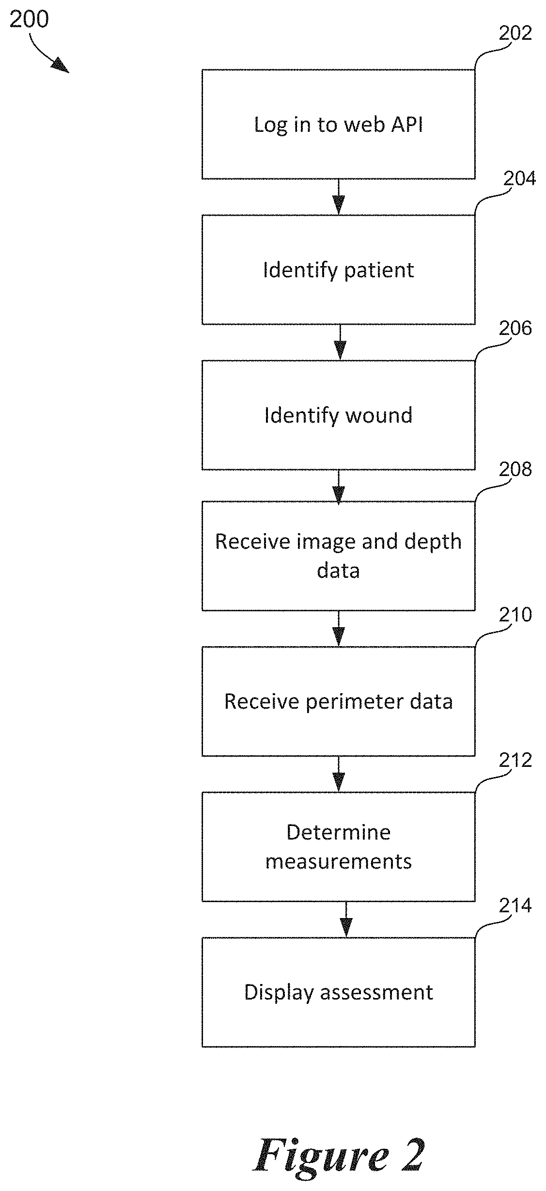
FIG. 2 is a flow diagram showing steps typically performed by the facility to automatically assess an anatomical surface feature of a human patient.
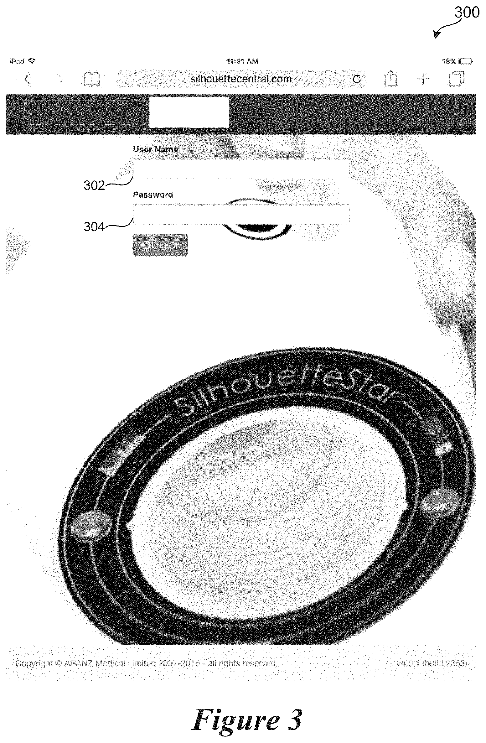
FIG. 3 is a display diagram showing a sample display typically presented by the facility to permit the user to enter a username and password to access the facility.
FIG. 4 is a display diagram showing a sample display typically presented by the facility to permit the user to select an existing patient profile and/or create a new patient profile.
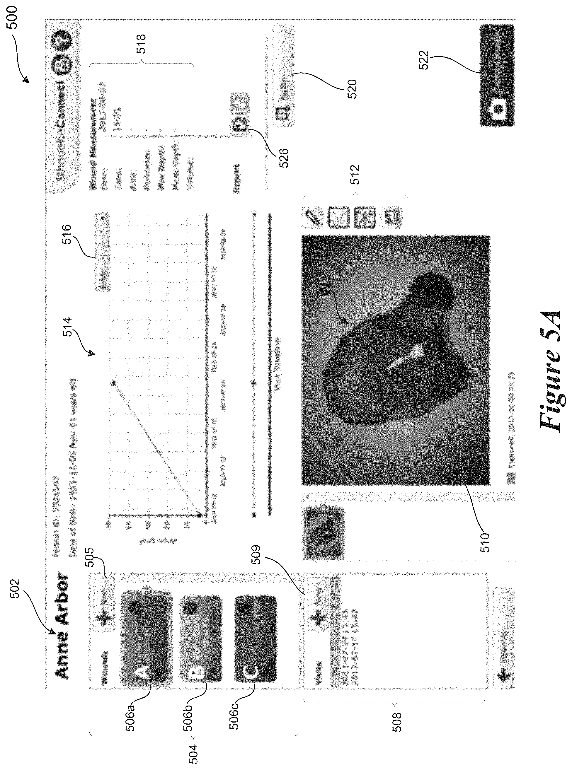
FIG. 5A is a display diagram showing a sample display typically presented by the facility to display surface feature information for a selected patient and enable the user to capture additional images of the surface feature.
FIG. 5B is a display diagram showing a sample display typically presented by the facility to enable the user to automatically couple a particular capture device to the facility.
FIG. 6 is a display diagram showing a sample display typically presented by the facility to display one or more captured images and enable the user to assign a new image to a pre-existing wound.
FIG. 7 is a display diagram showing a sample display typically presented by the facility to display a captured image of a surface feature and enable the user to outline the perimeter of the surface feature within the captured image.
FIG. 8 is a display diagram showing a portion of the display shown in FIG. 7 after the facility has determined one or more measurements characterizing the surface feature and has displayed those measurements to the user.
FIG. 9 is a display diagram showing a sample display typically presented by the facility to present an updated surface feature assessment for a selected patient.
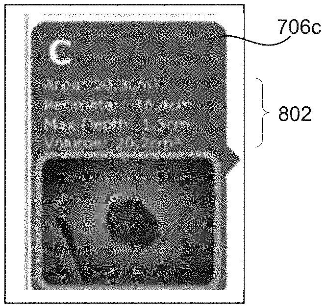
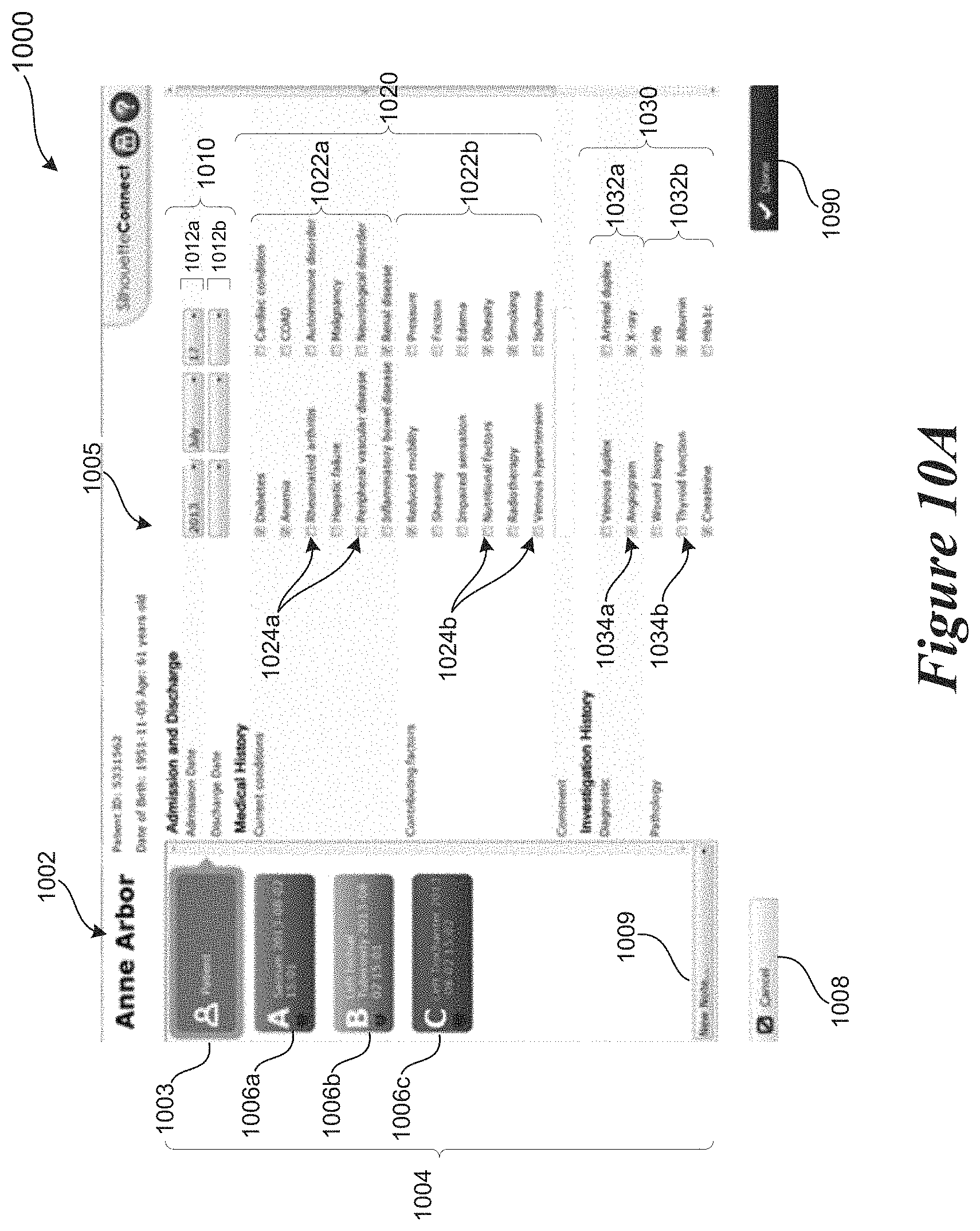
FIGS. 10A-10D are display diagrams showing sample displays typically presented by the facility to enable the user to provide notes characterizing the surface feature.
FIG. 11 is a display diagram showing a sample display typically presented by the facility when the user selects the create report button.
FIGS. 12A-12D are display diagrams showing a sample display typically presented by the facility to display a report characterizing the surface feature.
DETAILED DESCRIPTION
Overview
Described herein is a software facility for automatically assessing an anatomical surface feature ("the facility"), such as a wound, and for managing information related to assessed anatomical surface features across a range of patients and institutions. While the following discussion liberally employs the term "wound" to refer to the anatomical surface feature(s) being assessed, those skilled in the art will appreciate that the facility may be straightforwardly applied to anatomical surface features of other types, such as ulcers, sores, lesions, tumors, bruises, burns, moles, psoriasis, keloids, skin cancers, erythema, cellulitis, and the like. Similarly, a wide variety of users may use the facility, including doctors, nurses, technologists, or any other caregiver of the patient.
As used herein, the terms "computer" and "computing device" generally refer to devices that have a processor and non-transitory memory, as well as any data processor or any device capable of communicating with a network. Data processors include programmable general-purpose or special-purpose microprocessors, programmable controllers, application-specific integrated circuits (ASICs), programming logic devices (PLDs), system on chip (SOC) or system on module (SOM) ("SOC/SOM"), an ARM class CPU with embedded Linux or Android operating system or the like, or a combination of such devices. Computer-executable instructions may be stored in memory, such as random access memory (RAM), read-only memory (ROM), flash memory, or the like, or a combination of such components. Computer-executable instructions may also be stored in one or more storage devices, such as magnetic or optical-based disks, flash memory devices, or any other type of non-volatile storage medium or non-transitory medium for data. Computer-executable instructions may include one or more program modules, which include routines, programs, objects, components, data structures, and so on that perform particular tasks or implement particular abstract data types.
Anatomical Surface Feature Assessment
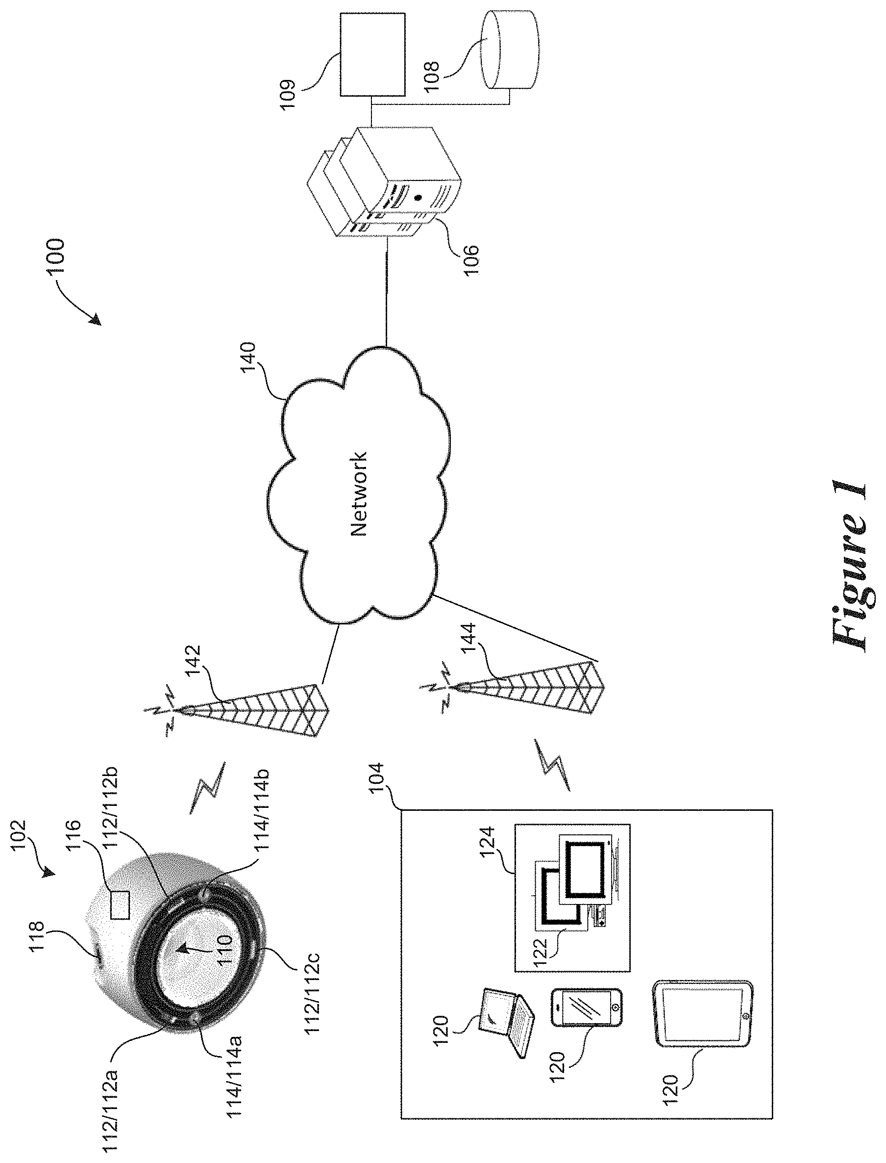
FIG. 1 is a block diagram showing a sample environment having multiple components n which the facility executes. The environment 100 may include one or more capture devices 102, one or more personal computing devices 104, one or more server computers 106, and one or more persistent storage devices 108. The capture device 102 and the personal computing device 104 communicate (wirelessly or through a wired connection) with the server computer 106 through a network 140 such as, for example, a Local Area Network (LAN), a Wide Area Network (WAN), and/or the Internet. In the embodiment shown in FIG. 1, the capture device 102 does not communicate directly with the personal computing device 104. For example, the capture device 102 may communicate wirelessly with a first base station or access point 142 using a wireless mobile telephone standard, such as the Global System for Mobile Communication (GSM), or another wireless standard, such as IEEE 802.11, and the first base station or access point 142 communicates with the server computer 106 via the network 140. Likewise, the computing device 104 may communicate wirelessly with a second base station or access point 144 using a wireless mobile telephone standard, such as the Global System for Mobile Communication (GSM), or another wireless standard, such as IEEE 802.11, and the second base station or access point 144 communicates with the server computer 106 via the network 140. As such, confidential patient data generated by the capture device 102 is only temporarily stored locally, or not at all, and instead is permanently stored at the storage device 108 associated with the server computer 106. The facility can be practiced on any of the computing devices disclosed herein (e.g., one or more personal computing devices 104, one or more server computers 106, etc.), and may include an interface module that generates graphical user interfaces (GUIs) to allow users to access the facility (as described in greater detail below with reference to FIGS. 3-12D).
The personal computing device 104 can include one or more portable computing devices 120 (e.g., a smart phone, a laptop, a tablet, etc.) and/or one or more desktop computing devices 122. During data capture with the capture device 102 at the point-of-care, the personal computing device 104 may also be present (i.e., in the same treatment room), or the personal computing device 104 may be remote (i.e., outside of the treatment room but in the same treatment facility, outside of the treatment room and remote from the treatment facility, etc.). The desktop computing devices 122, if utilized, are typically associated with a particular property, e.g., a medical treatment center 124 (e.g., a hospital, a doctor's office, a clinic, etc.). The portable computing devices 120 and desktop computing devices 124 communicate with each other and the server computer 106 through networks including, for example, the Internet. In some instances the portable computing devices 120 and desktop computing devices 122 may communicate with each other through other wireless protocols, such as near field or Bluetooth.
The capture device 102 is a handheld, portable imaging device that includes one or more sensing devices for generating data characterizing the wound ("wound data") at the point-of-care. In the embodiment shown in FIG. 1, the capture device 102 includes an image sensor 110 (e.g., a digital camera), a depth sensor 112 (also known as a "range imager"), and a computing device 116 (shown schematically) in communication with the image sensor 110 and the depth sensor 112. The computing device 116 is also in wireless communication with the server computer 106 (e.g., via the network 140). The image sensor 110 is configured to generate image data of the wound (e.g., pixels containing RGB color data), and the depth sensor 112 is configured to generate depth data characterizing the depth or topography of the wound. For example, in some embodiments the depth sensor 112 is a structured light device configured to emit structured light (e.g., one or more lasers, DLP projectors, film projectors, etc. where the emitted light may be infra-red, visible, ultraviolet, etc.) in a predetermined arrangement toward the wound. In such embodiments, for example, the depth sensor 112 may comprise three laser elements (labeled 112a-112c) spaced apart around a circumference of the capture device 102. The laser elements 112a-112c have a fixed positional relationship with respect to one another, and also with respect to the image sensor 110. Together the laser elements 112a-112c can be configured to create a structured light pattern (e.g., a laser point(s), a laser fan(s), etc.) In other embodiments, the depth sensor 112 can include other suitable devices for range imaging, such as an ultrasonic sensor, a stereo camera, a plenoptic camera, a time-of-flight camera, etc.
The capture device 102 also includes a rechargeable power source and an actuator 118 (e.g., a button, a switch, etc.) for initiating data capture. When a user presses the button 118, the computing device 116 simultaneously activates both the image sensor 110 and the depth sensor 112 to generate both the image data and the depth data. The computing device 116 then communicates the image data and the depth data to the remote server computer 106 for further processing by the facility. In some embodiments, the computing device 116 wirelessly communicates with the server computer 106 (e.g., over a network). Such a cordless arrangement can be advantageous as it allows the user greater freedom of movement with the capture device 102, which can be especially beneficial when trying to access certain anatomical locations. Also, the absence of a cord reduces the surface area available at the point-of-care on which bacteria and/or other unwanted microorganisms may bind and travel. In some embodiments, the capture device 102 may be permanently cordless (i.e., no input port), and in other embodiments, the capture device 102 may be configured to detachably receive an electronic connector, such as a power cord or a USB cord. The computing device 116 may automatically transfer the captured data to the remote server computer 106 (e.g., over the network 140) at the moment the data is captured. In certain embodiments, however, the computing device 116 may not be in communication with the network 140; in such scenarios, the captured data may be temporarily stored in the volatile and/or non-volatile memory of the capture device 102 for later transfer to the server computer 106.
The capture device 102 may include additional features for enhancing data collection of the wound, such as one or more light sources 114 (e.g., a light emitting diode (LED), an incandescent light source, an ultraviolet light source, etc.) for illuminating the wound before or during data capture, an indicator (not shown) configured to provide a visual and/or audio signal (e.g., images, text, lights, etc.) to the user, a thermal camera, a video camera, and/or one or more input/output devices (e.g., a microphone, a speaker, a port for communicating electrically with external components, such as a power source, the personal computing device 104, etc.). In some embodiments, the capture device 102 is configured for wireless charging, e.g., via a dock or cradle (not shown). In such embodiments, the charging cradle may also serve as an access point for the network 140. As discussed in greater detail below with reference to FIGS. 5A-5B, the capture device 102 and/or image sensor 110 may also be configured to capture images of barcodes and/or QR codes displayed on the computing device 104, such as a barcode and/or a QR code that enable the capture device 102 to connect to the network 140.
Those skilled in the art will appreciate that the capture device 102 may have other configurations than that shown in FIG. 1. For example, although the image sensor 110, depth sensor 112, and computing device 116 are shown as part of a single component and/or within the same housing, in other embodiments, any or all of the of the image sensor 110, the depth sensor 112, and the computing device 116 can be separate components. Likewise, in some embodiments, the capture device 102 does not include separate image and depth sensors, and instead includes a stereo camera that is configured to generate both image data and depth data. Additional details regarding suitable capture devices 102 and methods of use can be found in U.S. Pat. No. 8,755,053, filed May 11, 2009 and U.S. Pat. No. 9,179,844, filed Nov. 27, 2012, both of which are incorporated herein by reference in their entireties.
As discussed above, the facility may include an interface module that generates graphical user interfaces (GUIs) to allow users to access the facility. The interface module also provides application programming interfaces (APIs) to enable communication and interfacing with the facility. APIs may be used by other applications, web portals, or distributed system components to use the system. For example, an application operating on a personal computing device may use an API to interface with system servers and receive capture data from the system. The API may utilize, for example, Representational State Transfer (REST) architecture and Simple Object Access Protocol (SOAP) protocols.
FIG. 2 is a flow diagram showing steps typically performed by the facility to assess a wound of a patient and/or manage data (including meta data) related to the wound. At step 202, the facility provides a display that solicits the user to enter login information (e.g., a username and password) to permit the user to access the facility and/or the storage device 108 (see, for example, FIG. 3). At step 204, the facility solicits the user to identify the patient having a wound needing assessment (see, for example, FIG. 4). If the patient is new to the database, the facility enables the user to create a new data structure (or profile) for the patient, and a new data structure (or profile) for the wound that is associated with the patient's profile. If the patient already exists in the database, then the facility displays a unique identifier for the patient or otherwise enables the user to access the already-existing patient profile. Once the facility has identified the patient, the facility solicits the user to identify the wound to be reviewed and/or assessed (see, for example, FIG. 5A). If the wound has not yet been entered into the patient profile, the facility enables the user to create a new data structure (or profile) for the wound and associates that data structure with the already-existing patient profile. If the wound already exists in the patient profile, then the facility displays a unique identifier for the particular wound or otherwise enables the user to access the already-existing wound profile. At some point after the facility has identified the corresponding patient and wound profile, the facility receives new image data, new depth data, and new outline data characterizing the wound and assigns the new data to the wound profile (steps 208-210). As shown at steps 212-214, the facility then analyzes this data to determine one or more wound measurements (such as wound area and wound volume), and displays the wound measurements to the user.
Those skilled in the art will appreciate that the steps shown in FIG. 2 may be altered in a variety of ways. For example, the order of the steps may be rearranged, sub steps may be performed in parallel, shown steps may be omitted, other steps may be included, etc.
FIGS. 3-12D contain sample displays presented by the facility in some embodiments in performing portions of the method shown in FIG. 2. In the following discussion, the user interacts with the facility through a web-based interface, and thus all tasks or modules of the facility are performed at a remote server computer (such as server computer 106). However, the facility can also be practiced in distributed computing environments, where tasks or modules of the facility are performed by multiple remote processing devices (such as the personal computing device 104 and the server computer 106), which are linked through a communications network, such as a Local Area Network ("LAN"), Wide Area Network ("WAN"), or the Internet. For example, those skilled in the relevant art will recognize that portions of the facility may reside on a server computer, while corresponding portions reside on a remote or personal computing device. In such a distributed computing environment, program modules or subroutines may be located in and executed on both local and remote memory storage devices. Aspects of the facility described herein may be stored or distributed on tangible, non-transitory computer-readable media, including magnetic and optically readable and removable computer discs, stored in firmware in chips (e.g., EEPROM chips). Alternatively, aspects of the facility may be distributed electronically over the Internet or over other networks (including wireless networks).
To begin a wound assessment, a caregiver may first provide a username and password to gain access to the interface module. For example, FIG. 3 is a display diagram showing a sample display 300 typically presented by the facility that solicits the user to enter a username and password to access the programs and data stored at the storage device 108. As shown in FIG. 3, the display 300 includes a username field 302 and a password field 304.
FIG. 4 is a display diagram showing a sample display 400 typically presented by the facility to permit the user to select an existing patient profile and/or create a new patient profile. The display 400 includes a generic search field 412 for searching for a particular patient by name, birthday, unique identifier, and/or assessment date. The display 400 further includes a control 404 to create a new patient profile. The display 400 may also include an existing patient table 402 listing existing patient profiles in rows 421-424. Each row is divided into the following sortable and/or filterable columns: a first name column 431 containing the first name of an already-assessed patient, a last name column 432 containing the last name of an already-assessed patient, a date-of-birth column 433 containing the date of birth of an already-assessed patient, a patient ID column 434 containing the patient ID of an already-assessed patient, a "#" column 435 containing the number of wound assessments performed on the already-assessed patient, and a number of active orders column 436 containing indicated the number of orders for new assessments that are currently pending. Orders for new assessments might come, for example, from an Electronic Medical Records (EMR) system attached to the server computer 106. In the sample display 400 shown in FIG. 4, row 421 indicates that patient Harriet Jones has at least one wound that has been previously assessed by the facility, and that Harriet Jones' date of birth is Jan. 15, 1976 and patient ID is 9990532, and that Harriet Jones has two assessments completed but no orders for another assessment. (It will be appreciated that the patient information used in the displays and examples herein are fictitious.) While the contents of patient table 400 are included to pose a comprehensible example, those skilled in the art will appreciate that the facility can use a patient table having columns corresponding to different and/or a larger number of attributes, as well as a larger number of rows to accommodate additional patients. Attributes that may be used include, for example, number of wounds actively being monitored, date and/or time of the most recent assessment, date and/or time of the first assessment, name or other identifier of the caregiver that gave the last assessment, etc. For a variety of reasons, certain values may be omitted from the patient table.
When the user clicks on one of the rows 421-424 of already-assessed patients listed (i.e., to selected a particular patient profile), the facility displays additional information on the selected patient. For example, FIG. 5A is a display diagram showing a sample wound information display 500 typically presented by the facility for review of wounds already being monitored or assessed by the facility. Display 500 includes a patient identifier 502, a wound identifier area 504, a visit area 508, an image area 510, an analytics area 514, and a wound measurement area 518. The wound identifier area 504 includes a button 505 for adding a new wound profile, as well as buttons 506a-506c, each of which correspond to a wound of the patient that is being monitored. As shown in FIG. 5A, the buttons 506a-506c identify the corresponding monitored wound by anatomical reference. For example, button A refers to a wound found at or near the sacrum of the patient. The buttons 506a-506c may also be color-coded. When the user selects one of the buttons 506a-506c, the facility displays information related to the selected wound, such as the most recent wound image 510, analytics 514 showing progress of the selected wound, and wound measurements 518. The sample display 500 of FIG. 5A shows a display after a user has selected wound A (by clicking on button 506a).
The visit area 508 displays the dates and times of previous assessments for the selected wound. The user may select a particular visit to review the wound assessment from the selected visit. The visit area includes a button 509 for creating a new visit for the selected wound. The wound image area 510 displays an image of the wound W. The default image is that from the most recent assessment (or visit), although the user can view wound images from earlier visits by selecting the particular visit in the visit area 508. The wound image area 510 can include buttons 512 that allow the user to manipulate the displayed image. In some embodiments, the wound image area 510 may include display a three-dimensional model of the wound. The wound measurement area 518 displays one or more wound measurements, such as wound area, wound volume, wound outline, the maximum depth of the wound, the minimum depth of the wound, etc. In display 500, the wound measurement area 518 is blank, as the user has not yet generated new capture data. As shown in the display 500' of FIG. 9 (discussed below), the facility will display the measurements once the user has captured new wound data. The analytics area 514 displays additional information to the user based on the facility's analysis of the wound measurements over time. For example, the analytics area 514 of the display 500 shows a graph plotting the measured area of wound A over time. The graph indicates that wound A has been previously assessed two times, and that the area of the wound increased between those assessments. The analytics area 514 may include a button 516 that, when selected, displays a drop-down menu of wound measurement options that may be plotted over time and displayed for the user.
In some embodiments, the facility may enable the user to couple (i.e., pair, associate, etc.) the capture device 102 to the facility so that the capture device 102 may automatically send captured data to a specific patient profile in the storage device 108 that is accessible by the facility for processing. In FIG. 5A, for example, the display 500 includes a button 522 that, when selected by the user, causes the facility to dynamically generate coupling information. FIG. 5B is a display diagram showing a sample display 550 having coupling information 556 that may be presented by the facility to the user. In FIG. 5B, the coupling information 556 is displayed as a QR code. In other embodiments, however, the coupling information 556 can have other configurations, such as a bar code, text that the user may enter into an input element of the capture device 102, etc. The user may scan or otherwise detect the coupling information 556 with the capture device 102 (e.g., via the image sensor 110 of the capture device 102) to automatically place the capture device 102 in communication with a particular patient profile in the storage device 108. The coupling information 556, for example, can include a network identifier and password (e.g., an SSID and SSID password), an Internet address (e.g., the URL for the interface module), and a patient identifier for directing the capture device 102 to the particular patient profile at the storage device 108. Once the capture device 102 is wirelessly coupled to the server computer 106 and/or storage device 108, the user can position the capture device 102 near the wound being assessed and begin capturing wound data. Each time the user actuates the actuator 118 (FIG. 1) on the capture device 102, the capture device 102 automatically populates the patient profile at the storage device 108 with a new data set. The user may select button 554 to view the captured images and/or data. Each new data set may be displayed by the facility as an unassigned image button, as discussed in greater detail below with reference to FIG. 6.
It will be appreciated that the coupling information 556 may be encrypted to protect the patient's confidential information. For example, in the embodiment shown in FIG. 5B, the QR code 556 is encrypted such that a screen shot of display 552 will not provide the coupling information and/or provide access to a recipient of the screen shot.
The present technology includes additional methods for coupling the capture device 102 to the facility. For example, in some embodiments, some or all of the coupling information may be received from an identifier on the patient, such as a patient wristband. As another example, in some embodiments the facility may display a list of capture devices 102 available on the network 140 (FIG. 1) (e.g., a plurality of capture devices 102 may be dispersed amongst different examination rooms in a medical treatment center, and at least a portion of those devices may be coupled to the same wireless network). The facility may display (e.g., via the interface module) each of the capture devices 102 available, and enable the user to select the appropriate capture device 102 for pairing. The facility may then solicit the user to input a patient identifier and/or additional information for connecting the capture device 102 to the facility and/or server computer 106. In yet another embodiment, the capture device 102 may be placed in direct communication with the personal computing device 104 (e.g., via a USB cord), and the user may input pairing information into a local program executing on the personal computing device 104 and/or a web-based interface executing on the remote server computer 106.
In some embodiments (not shown), the wound information display 500 includes a button that, when selected by the user, causes a live image from the capture device 102 (FIG. 1) to be displayed on the interface module. For example, should the personal computing device 104 also be present at the point-of-care, the user may utilize the display of the personal computing device 104 to properly position the capture device 102 from the wound. In other embodiments, the capture device 102 has a display and/or the facility does not display a live image of the wound on the personal computing device 104 during image capture. The facility may further include a button (not shown) on the image capture display (not shown) that, once the user is finished capturing wound data, the user may select the button to begin assigning the captured images (containing the image data and the depth data) to the corresponding wound profile. For example, FIG. 6 is a display diagram showing a sample display 600 typically presented by the facility to display one or more captured images and enable the user to assign newly-captured wound data with a pre-existing wound. As shown in FIG. 6, the display 600 includes a new image area 604, a wound identifier area 612 having buttons 614 (similar to buttons 506a-506c in FIG. 5A), an image area 616, and a trace button 618. The new image area 604 includes an "unassigned" area 603 having buttons 606a-606e, each of which correspond to a new or unassigned image. Each of the buttons 606a-606e may include a small, preview image of the captured image so that the user can easily distinguish between the new images. To assign a new image to a wound profile, the user may drag and drop the button 606a-606e over the corresponding button 614a-c in the wound area. The facility also displays a discard button 615 for the user to remove unwanted images.
Once the captured data has been assigned to a corresponding wound profile, the user may select the trace button 618, which causes the facility to display an interface that solicits the user to manually trace the outline of the wound. In certain embodiments, the facility utilizes image processing techniques to automatically determine an outline or outline of the wound. In such embodiments, the facility may nevertheless solicit the user to view and edit the automatically generated outline. FIG. 7, for example, is a display diagram showing a sample display 700 typically presented by the facility to display a captured image of a wound W and solicit the user to outline the outline of the wound within the captured image. The display 700 includes an image identifier area 704 and an editing area 705. The identifier area includes buttons 706a-706c (only buttons 706b and 706c shown in FIG. 7) that identify the image (with a preview image) and wound (e.g., by color and/or by reference letters "B" and "C" that correspond to a particular wound profile). When a user selects a button 706a-706c, an enlarged view of the image appears in the editing area 705. The editing area 705 includes editing buttons 710 that enable the user to edit or manipulate the image. Button 710a, for example, enables the user to click various points around the outline of the wound W, and the facility automatically displays a line (line "a") connecting the points. Button 710b enables the user to draw a continuous line (line "b") around the outline of the wound W. As shown in FIG. 7, the resulting outline line can be a combination of one or both techniques. In other embodiments, the facility may include other editing techniques. For example, in a particular embodiment, the facility may display a suggested outline line for the user and one or more buttons for adjusting the automatically generated line.
Once the outline data is generated (either automatically by the facility, manually by the user's input, or a combination of both), the facility then utilizes the captured data (image data and depth data) and the outline data to determine one or more wound measurements, which in some embodiments may include generating a three-dimensional model of the wound. The facility may then update the corresponding wound identifier button 706a-706c to display the determined wound measurements. FIG. 8, for example, is a display diagram showing an enlarged view of the button 706c shown in the display 700 of FIG. 7 after being updated to include the newly determined wound measurements 802.
FIG. 9 is an updated version 500' of the sample wound information display 500 (FIG. 5A) after the facility has updated the measurement area 518', image area 510', and analytics area 514' to include the new capture data, outline data, and wound measurements. Updated graph 514', for example, includes an additional data point (as compared to the graph of FIG. 5A).
The facility may optionally include a button 520 that enables the user to enter additional notes characterizing a wound and/or the patient. For example, FIGS. 10A-10D are display diagrams showing a sample display 1000 presented by the facility to the user when the user selects button 520. The display 1000 includes an identifier area 1004 having a patient button 1003 and wound identifier buttons 1006a-c (similar to buttons 506a-c), and a notation area 1005. After selecting any of the patient buttons 1003 and wound identifier buttons 1006a-c, the facility displays a notation area 1005 solicits the user for input regarding the selected patient and/or wound. Display 1000 shows a sample notation area 1005 after the user has selected the patient button 1003. As shown in FIGS. 10A-10D, the notation area 1005 can include various topic areas 1010, 1020, 1030, 1040, 1050, 1060, 1070, and 1080 (referred to collectively as "topic areas 1010-1080"), such as admission and discharge, medical history, investigation history, wound appearance, wound margins, surrounding skin, exudate, and wound pain. It will be appreciated that the facility may display more or fewer notation topics. The facility may divide each of the topic areas 1010-1080 into one or more sub-topics (the sub-topics for topic area 1020 are labeled 1022a, 1022b, etc.), and each of the sub-topics may include one or more input options (the input options for sub-topic 1022a are labeled 1024a, etc.). In some embodiments, the facility may include a text field (not shown) that enables the user to enter personalized notes. When the user is finished, the user may select the "done" button 1090 to return to the updated wound information display 500' (FIG. 9).
The facility also enables the user to generate a report one or more of the wounds, or the patient, generally. For example, FIG. 11 is a display diagram showing a sample display 1100 typically presented by the facility when the user selects the "create report" 526 button on the wound information display 500, 500', and FIGS. 12A-12D, for example, are display diagrams showing a sample display 1200 typically presented by the facility to display the generated report.
Although the facility is described above as providing the user a means of interacting by displaying one or more selectable buttons, it will be appreciated that other means of interacting with or controlling the facility, personal computing device, and/or capture device are within the scope of the present technology. For example, in some embodiments, in addition to or in place of any of the buttons described above, the user may interact with the facility with audio (via a microphone) and/or tactile commands (e.g., a foot control, etc.).
In those embodiments of capture devices 102 having a plurality of structured light elements (such as lasers), the capture device 102 may be configured to capture data based on a predetermined capture sequence (for example, instructions executed by the computing device 116 (FIG. 1)). An example capture sequence utilized by the capture device 102 starts with an RGB (or texture) frame captured while the light source 114 (FIG. 1) emits light. The RGB frame is followed by capture of individual frames for each structured light element (a frame is captured while each structured light element is turned on by itself), as well as a frame for the combination of structured light elements. During capture of the RGB frame, the structured light elements 112 do not emit light. Likewise, during capture of the structured light frames, the light source 114 does not emit light. However, post-capture processing methods require that only one type of light source (regardless of the number of light sources per type) is enabled during the capture sequence. Existing imaging devices meet this requirement by configuring the image sensor to operate in a "single frame capture mode" (i.e., pauses are inserted between consecutive frames of the capture sequence). However, because of the added pauses, "single frame capture mode" results in an increase in total capture time. To address this shortcoming, the image sensor 110 may be configured to operate in video mode (continuous streaming) which reduce capture times because it eliminates the pauses and "pipelines" the imaging processing steps. Suitable image sensors that operate in video mode include, for example, a 5-megapixel Omnivision OV5640 image sensor. Such image sensors, however, often utilize a rolling shutter (i.e., only a fraction of the sensor rows are exposed to light at any instant). For some of the image sensors that utilize a rolling shutter, the end the current frame and the beginning of the next frame overlap, and thus two disjoint fractions of the sensor rows are exposed to light at the same instant. This overlap results in cross-talk between successive frames. To avoid the potential for such cross-talk to reduce the utility of the captured frames, a specific capture sequence is employed and one or more multiplicative binary masks are applied to the structured light frames that reject the cross-talk from the previous frame (and also the next frame in cases where illumination for the next frame is pre-enabled) and also range gate the laser returns to certain depths (e.g., between 200 mm and 350 mm). In these and other embodiments, the image sensor 110 may additionally or alternatively be configured to operate in a "single frame capture mode." Additionally, because the capture device 102 is a handheld device and relative motion inevitably occurs between the capture device 102 and the patient over the course of the capture sequence, the facility and/or capture device 102 of the present technology may include one or more motion compensation algorithms to reduce or eliminate the negative effect of such motion on the resulting image and/or data quality.
Conclusion
It will be appreciated by those skilled in the art that the above-described facility may be straightforwardly adapted or extended in various ways. For example, the facility may use a variety of user interfaces to collect various information usable in determining valuations from users and other people knowledgeable about homes, and a variety of user interfaces to display refined valuations. While the foregoing description makes reference to particular embodiments, the scope of the invention is defined solely by the claims that follow and the elements recited therein.
While computing devices configured as described above are typically used to support the operation of the facility, one of ordinary skill in the art will appreciate that the facility may be implemented using devices of various types and configurations, and having various components. For example, in some instances the capture devices 102 and the personal computing devices 104 may communicate directly with each other (in addition to communicating with the server computer 106) through a wired or wireless connection. Such a configuration could provide the user a live image of the wound faster and/or provide a higher quality live preview image. In such embodiments, suitable restrictions can be administered when sending and storing patient data to ensure confidentiality. In another variation, the capture device 102 is only in communication (wired or wirelessly) with the computing device 104, and the computing device 104 communicates with the server computer 106 (e.g., via cellular data protocols), thereby serving as a pass through for patient data without permanently storing the patient data. In yet another variation, the facility may route communications from the capture devices 102 and the computing devices 104 through a common access point, rather than the two separate access points (first and second access points 140, 142) shown in FIG. 1. Additionally, the facility may provide the user with audit information for the assessments (e.g., who performed the assessments, who accessed the assessments, etc.).
Although not required, aspects of the present technology have been described in the general context of computer-executable instructions, such as routines executed by a general-purpose computer, a personal computer, a server, or other computing system. The present technology can also be embodied in a special purpose computer or data processor that is specifically programmed, configured, or constructed to perform one or more of the computer-executable instructions explained in detail herein.
* * * * *
References
-
comp.glam.ac.uklpages/staff/tjones/ThesisOL/Title.Htm
-
journalofwoundcare.com/nav?page=jowc.article&resource=I455125
-
findarticles.com/p/articles/mi_qa3977/is_200201/ai_n904
-
worldwidewounds.com/2000/sept/Michael-Lunt/Dopple
-
findarticles.com/p/articles/mi_mOMDQ/is_4_8/ai_n16043804/print
-
npuap.org
-
lmedscape.com/viewarticle/430900_print
-
guidelines.gov/content.aspx?id=9830&search=Pressure+Ulcer
-
wound.smith-nephew.com/us/node.asp?NodeId=3I20
-
smith-nephew.com
-
woundcare.org/newsvol2n4/arl.htm
-
-
gateway.ut.ovid.com.ezproxy.otago.ac.nzigw2/ovidweb.cgi
-
-
emedicine.com/pmr/topic179.htrn
-
care.diabetesjournals.org/cgi/content/full/30/I0/2641?ck=nck
-
ncbi.nlm.nih.gov/pubmed/I8630436?ordinalpos=I&itool=E
-
podiatrytoday.com/article/5831
D00000
D00001
D00002
D00003
D00004
D00005
D00006
D00007
D00008
D00009
D00010
D00011
D00012

D00013
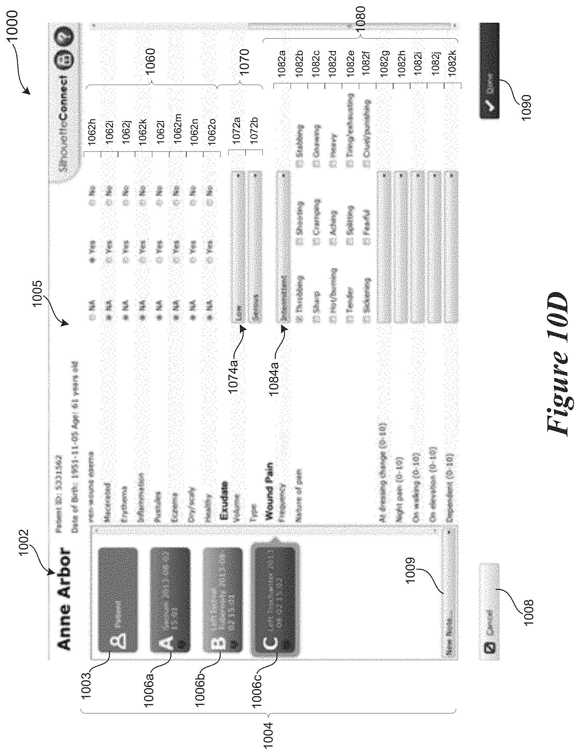
D00014

D00015
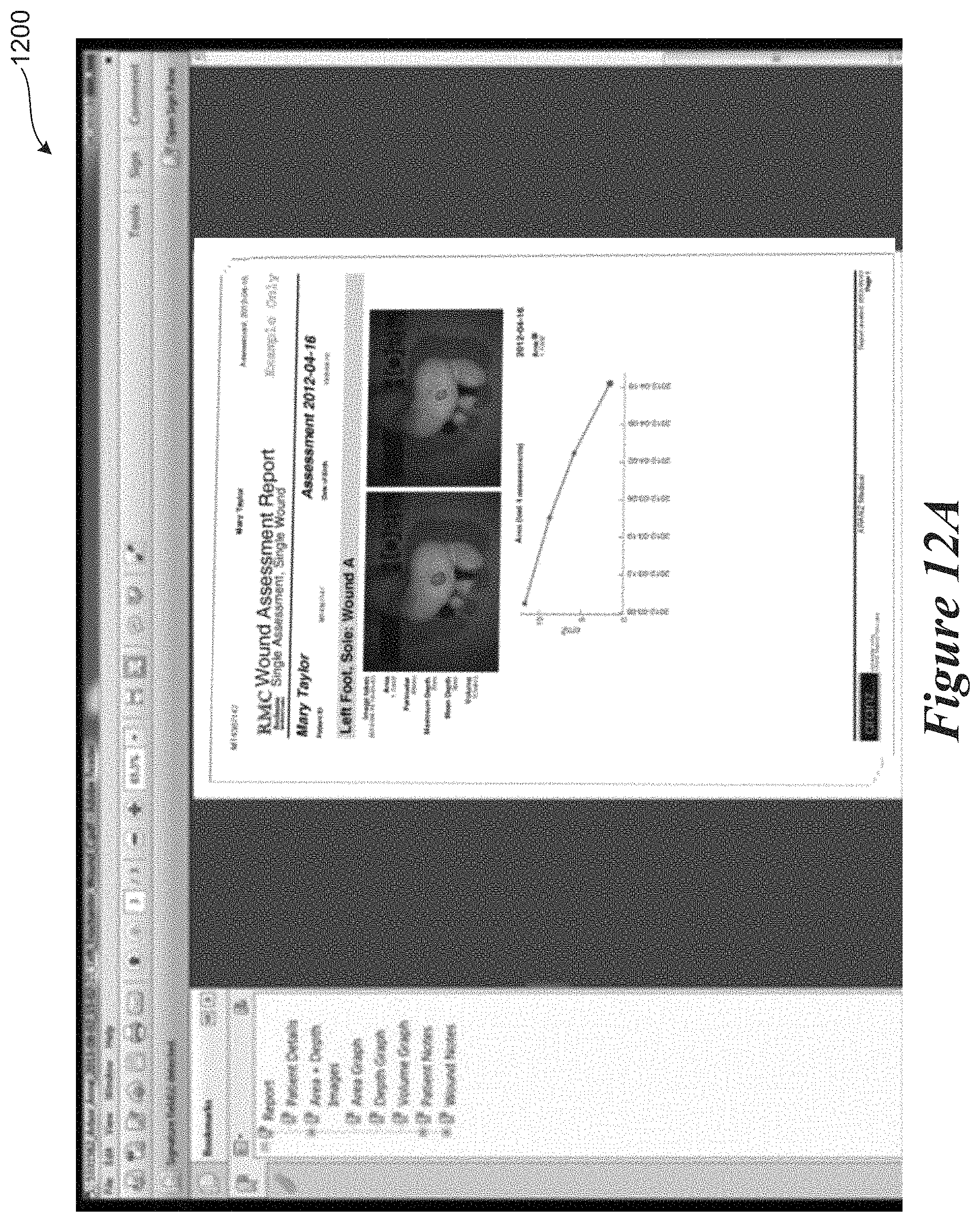
D00016
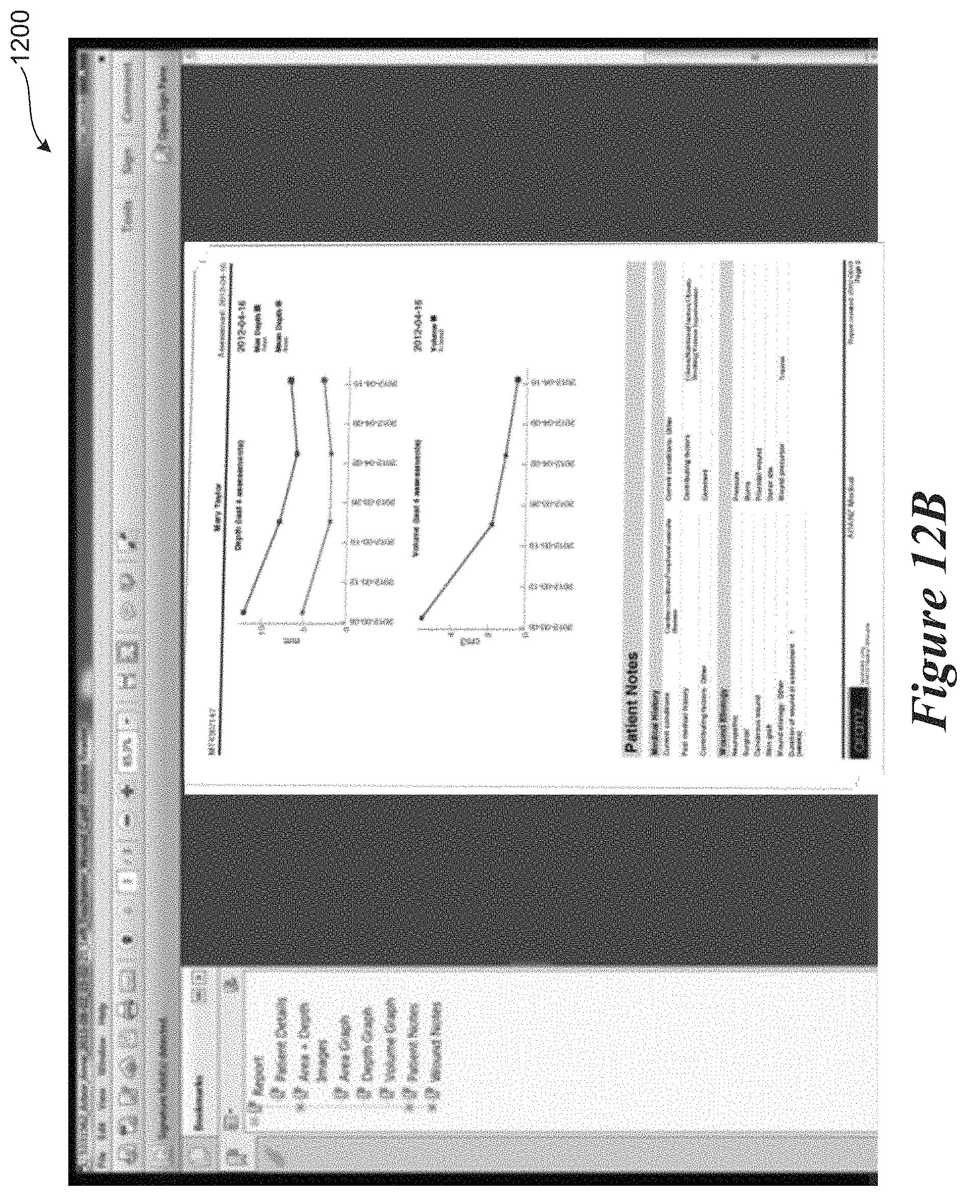
D00017

D00018

XML
uspto.report is an independent third-party trademark research tool that is not affiliated, endorsed, or sponsored by the United States Patent and Trademark Office (USPTO) or any other governmental organization. The information provided by uspto.report is based on publicly available data at the time of writing and is intended for informational purposes only.
While we strive to provide accurate and up-to-date information, we do not guarantee the accuracy, completeness, reliability, or suitability of the information displayed on this site. The use of this site is at your own risk. Any reliance you place on such information is therefore strictly at your own risk.
All official trademark data, including owner information, should be verified by visiting the official USPTO website at www.uspto.gov. This site is not intended to replace professional legal advice and should not be used as a substitute for consulting with a legal professional who is knowledgeable about trademark law.