Systems and methods for estimating depth from projected texture using camera arrays
Venkataraman , et al. Sep
U.S. patent number 10,767,981 [Application Number 16/177,191] was granted by the patent office on 2020-09-08 for systems and methods for estimating depth from projected texture using camera arrays. This patent grant is currently assigned to FotoNation Limited. The grantee listed for this patent is FotoNation Limited. Invention is credited to Jacques Duparre, Kartik Venkataraman.


View All Diagrams
| United States Patent | 10,767,981 |
| Venkataraman , et al. | September 8, 2020 |
Systems and methods for estimating depth from projected texture using camera arrays
Abstract
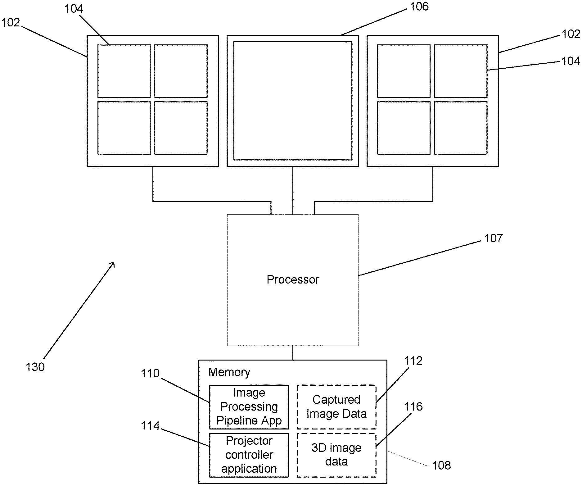
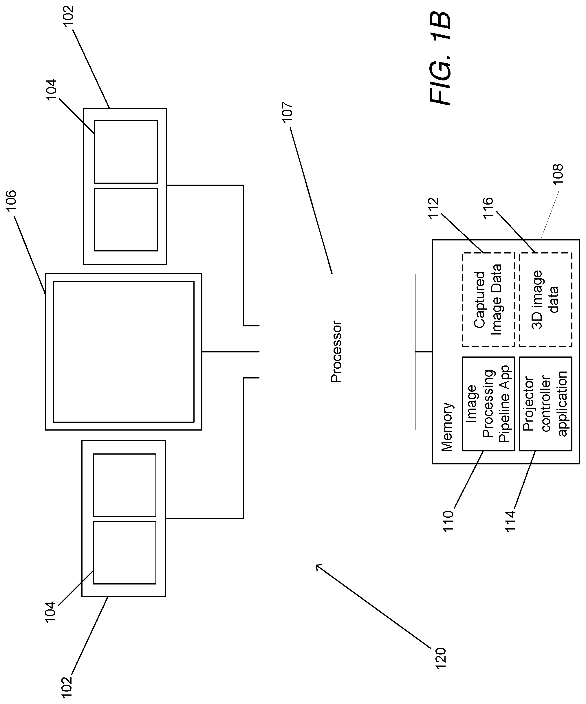
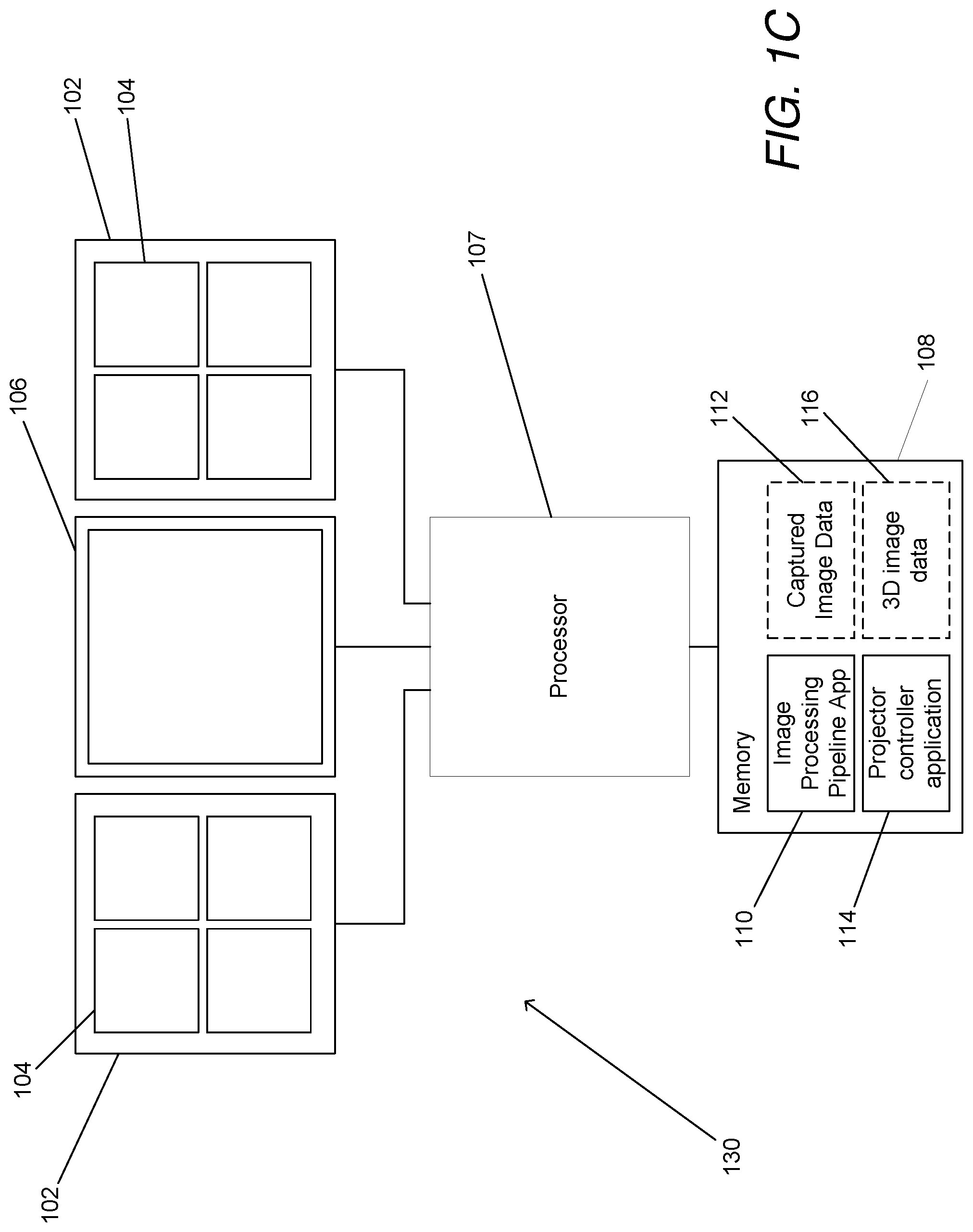
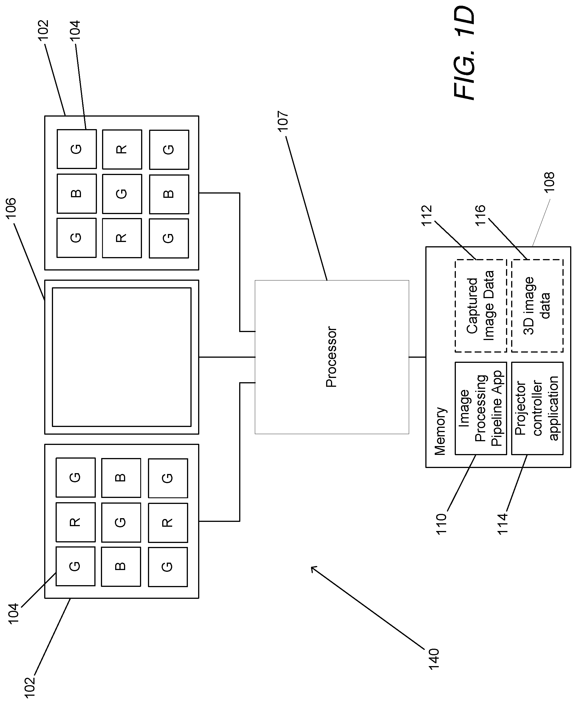
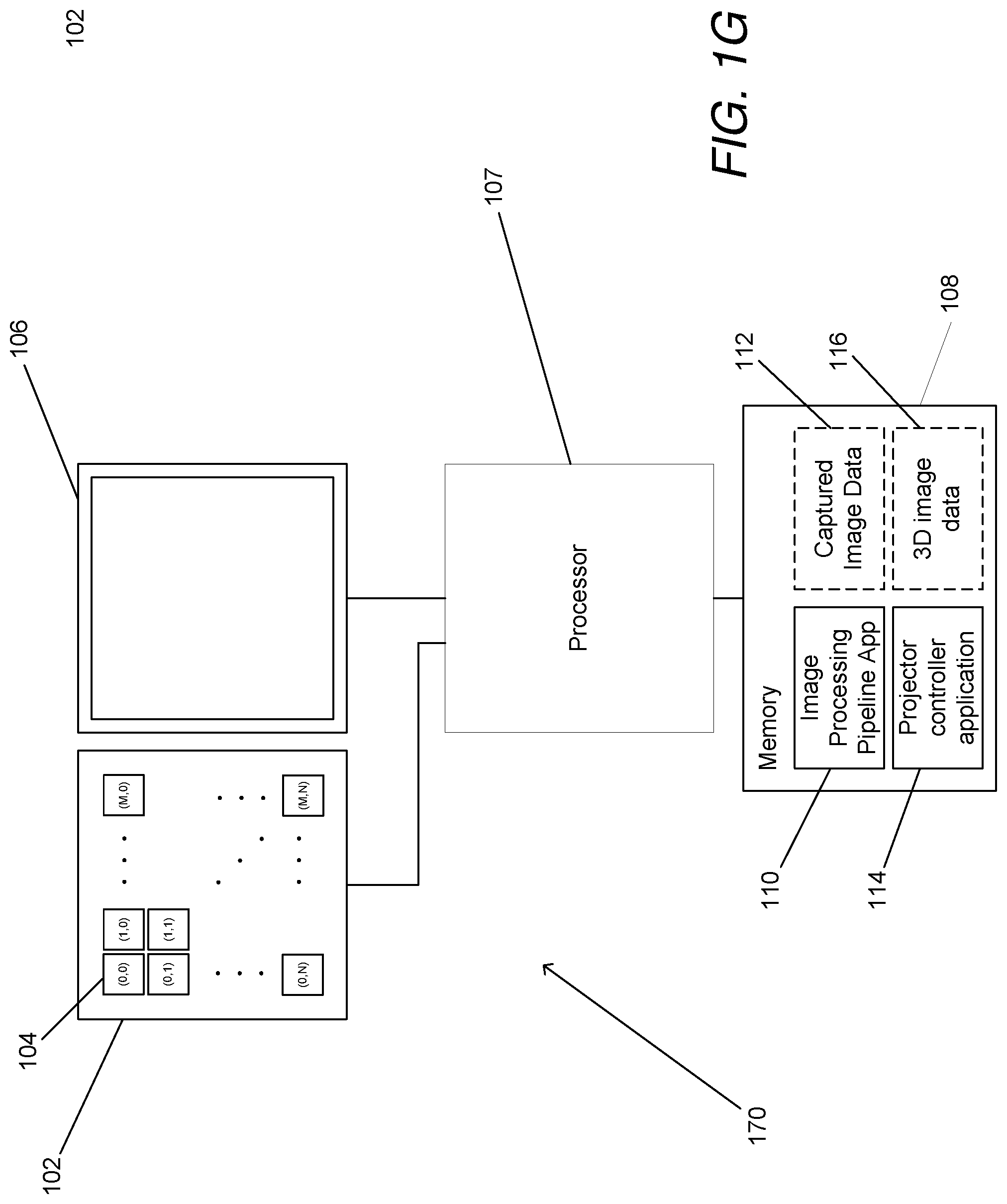
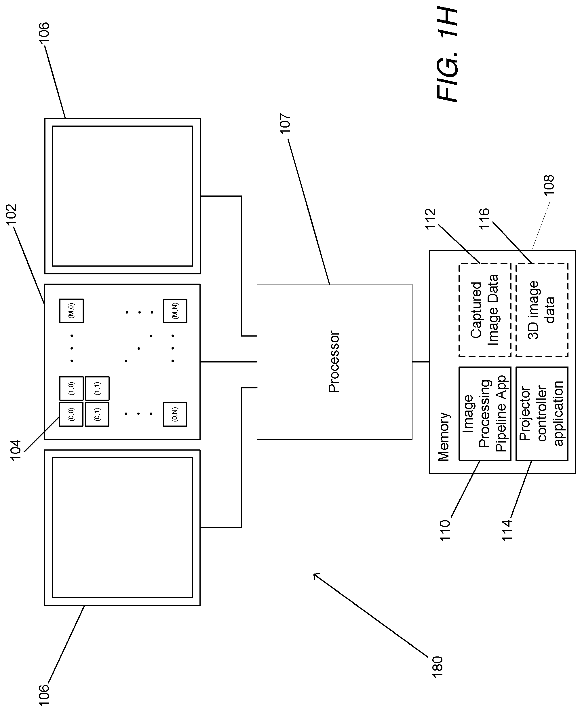
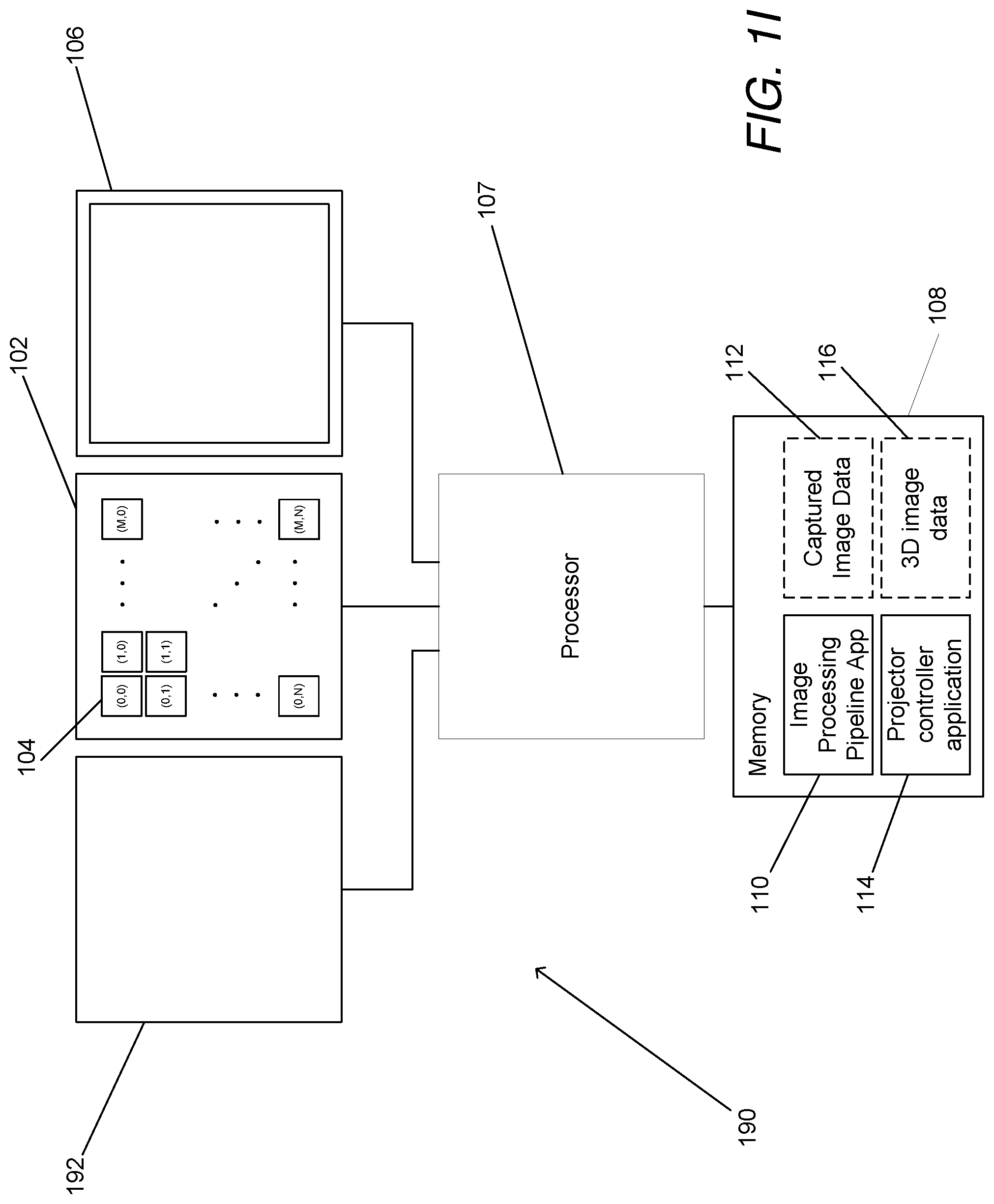
Systems and methods in accordance with embodiments of the invention estimate depth from projected texture using camera arrays. One embodiment of the invention includes: at least one two-dimensional array of cameras comprising a plurality of cameras; an illumination system configured to illuminate a scene with a projected texture; a processor; and memory containing an image processing pipeline application and an illumination system controller application. In addition, the illumination system controller application directs the processor to control the illumination system to illuminate a scene with a projected texture. Furthermore, the image processing pipeline application directs the processor to: utilize the illumination system controller application to control the illumination system to illuminate a scene with a projected texture capture a set of images of the scene illuminated with the projected texture; determining depth estimates for pixel locations in an image from a reference viewpoint using at least a subset of the set of images. Also, generating a depth estimate for a given pixel location in the image from the reference viewpoint includes: identifying pixels in the at least a subset of the set of images that correspond to the given pixel location in the image from the reference viewpoint based upon expected disparity at a plurality of depths along a plurality of epipolar lines aligned at different angles; comparing the similarity of the corresponding pixels identified at each of the plurality of depths; and selecting the depth from the plurality of depths at which the identified corresponding pixels have the highest degree of similarity as a depth estimate for the given pixel location in the image from the reference viewpoint.
| Inventors: | Venkataraman; Kartik (San Jose, CA), Duparre; Jacques (Jena, DE) | ||||||||||
|---|---|---|---|---|---|---|---|---|---|---|---|
| Applicant: |
|
||||||||||
| Assignee: | FotoNation Limited (Galway,
IE) |
||||||||||
| Family ID: | 1000005041984 | ||||||||||
| Appl. No.: | 16/177,191 | ||||||||||
| Filed: | October 31, 2018 |
Prior Publication Data
| Document Identifier | Publication Date | |
|---|---|---|
| US 20190063905 A1 | Feb 28, 2019 | |
Related U.S. Patent Documents
| Application Number | Filing Date | Patent Number | Issue Date | ||
|---|---|---|---|---|---|
| 14547048 | Nov 18, 2014 | 10119808 | |||
| 61905423 | Nov 18, 2013 | ||||
| Current U.S. Class: | 1/1 |
| Current CPC Class: | G06T 7/596 (20170101); G06T 7/557 (20170101); G01B 11/22 (20130101); G01B 11/2545 (20130101); G06T 7/521 (20170101); G06T 7/40 (20130101); G06T 2207/10024 (20130101) |
| Current International Class: | G01B 11/22 (20060101); G01B 11/25 (20060101); G06T 7/521 (20170101); G06T 7/593 (20170101); G06T 7/557 (20170101); G06T 7/40 (20170101) |
| Field of Search: | ;348/135 |
References Cited [Referenced By]
U.S. Patent Documents
| 4124798 | November 1978 | Thompson |
| 4198646 | April 1980 | Alexander et al. |
| 4323925 | April 1982 | Abell et al. |
| 4460449 | July 1984 | Montalbano |
| 4467365 | August 1984 | Murayama et al. |
| 4652909 | March 1987 | Glenn |
| 4899060 | February 1990 | Lischke |
| 4962425 | October 1990 | Rea |
| 5005083 | April 1991 | Grage |
| 5070414 | December 1991 | Tsutsumi |
| 5144448 | September 1992 | Hornbaker et al. |
| 5157499 | October 1992 | Oguma et al. |
| 5325449 | June 1994 | Burt |
| 5327125 | July 1994 | Iwase et al. |
| 5463464 | October 1995 | Ladewski |
| 5488674 | January 1996 | Burt |
| 5629524 | May 1997 | Stettner et al. |
| 5638461 | June 1997 | Fridge |
| 5757425 | May 1998 | Barton et al. |
| 5793900 | August 1998 | Nourbakhsh et al. |
| 5801919 | September 1998 | Griencewic |
| 5808350 | September 1998 | Jack et al. |
| 5832312 | November 1998 | Rieger et al. |
| 5833507 | November 1998 | Woodgate et al. |
| 5880691 | March 1999 | Fossum et al. |
| 5911008 | June 1999 | Niikura et al. |
| 5933190 | August 1999 | Dierickx et al. |
| 5963664 | October 1999 | Kumar et al. |
| 5973844 | October 1999 | Burger |
| 6002743 | December 1999 | Telymonde |
| 6005607 | December 1999 | Uomori et al. |
| 6034690 | March 2000 | Gallery et al. |
| 6069351 | May 2000 | Mack |
| 6069365 | May 2000 | Chow et al. |
| 6095989 | August 2000 | Hay et al. |
| 6097394 | August 2000 | Levoy et al. |
| 6124974 | September 2000 | Burger |
| 6130786 | October 2000 | Osawa et al. |
| 6137100 | October 2000 | Fossum et al. |
| 6137535 | October 2000 | Meyers |
| 6141048 | October 2000 | Meyers |
| 6160909 | December 2000 | Melen |
| 6163414 | December 2000 | Kikuchi et al. |
| 6172352 | January 2001 | Liu et al. |
| 6175379 | January 2001 | Uomori et al. |
| 6205241 | March 2001 | Melen |
| 6239909 | May 2001 | Hayashi et al. |
| 6292713 | September 2001 | Jouppi et al. |
| 6340994 | January 2002 | Margulis et al. |
| 6358862 | March 2002 | Ireland et al. |
| 6373518 | April 2002 | Sogawa |
| 6419638 | July 2002 | Hay et al. |
| 6443579 | September 2002 | Myers |
| 6445815 | September 2002 | Sato |
| 6476805 | November 2002 | Shum et al. |
| 6477260 | November 2002 | Shimomura |
| 6502097 | December 2002 | Chan et al. |
| 6525302 | February 2003 | Dowski, Jr. et al. |
| 6552742 | April 2003 | Seta |
| 6563537 | May 2003 | Kawamura et al. |
| 6571466 | June 2003 | Glenn et al. |
| 6603513 | August 2003 | Berezin |
| 6611289 | August 2003 | Yu |
| 6627896 | September 2003 | Hashimoto et al. |
| 6628330 | September 2003 | Lin |
| 6628845 | September 2003 | Stone et al. |
| 6635941 | October 2003 | Suda |
| 6639596 | October 2003 | Shum et al. |
| 6647142 | November 2003 | Beardsley |
| 6657218 | December 2003 | Noda |
| 6671399 | December 2003 | Berestov |
| 6674892 | January 2004 | Melen |
| 6750904 | June 2004 | Lambert |
| 6765617 | July 2004 | Tangen et al. |
| 6771833 | August 2004 | Edgar |
| 6774941 | August 2004 | Boisvert et al. |
| 6788338 | September 2004 | Dinev |
| 6795253 | September 2004 | Shinohara |
| 6801653 | October 2004 | Wu et al. |
| 6819328 | November 2004 | Moriwaki et al. |
| 6819358 | November 2004 | Kagle et al. |
| 6879735 | April 2005 | Portniaguine et al. |
| 6897454 | May 2005 | Sasaki et al. |
| 6903770 | June 2005 | Kobayashi et al. |
| 6909121 | June 2005 | Nishikawa |
| 6917702 | July 2005 | Beardsley |
| 6927922 | August 2005 | George |
| 6958862 | October 2005 | Joseph |
| 6985175 | January 2006 | Iwai et al. |
| 7015954 | March 2006 | Foote et al. |
| 7085409 | August 2006 | Sawhney |
| 7161614 | January 2007 | Yamashita et al. |
| 7199348 | April 2007 | Olsen et al. |
| 7206449 | April 2007 | Raskar et al. |
| 7215364 | May 2007 | Wachtel et al. |
| 7235785 | June 2007 | Hornback et al. |
| 7245761 | July 2007 | Swaminathan et al. |
| 7262799 | August 2007 | Suda |
| 7292735 | November 2007 | Blake et al. |
| 7295697 | November 2007 | Satoh |
| 7333651 | February 2008 | Kim et al. |
| 7369165 | May 2008 | Bosco et al. |
| 7391572 | June 2008 | Jacobowitz et al. |
| 7408725 | August 2008 | Sato |
| 7425984 | September 2008 | Chen |
| 7430312 | September 2008 | Gu |
| 7471765 | December 2008 | Jaffray et al. |
| 7496293 | February 2009 | Shamir et al. |
| 7564019 | July 2009 | Olsen |
| 7599547 | October 2009 | Sun et al. |
| 7606484 | October 2009 | Richards et al. |
| 7620265 | November 2009 | Wolff |
| 7633511 | December 2009 | Shum et al. |
| 7639435 | December 2009 | Chiang et al. |
| 7639838 | December 2009 | Nims |
| 7646549 | January 2010 | Zalevsky et al. |
| 7657090 | February 2010 | Omatsu et al. |
| 7667824 | February 2010 | Moran |
| 7675080 | March 2010 | Boettiger |
| 7675681 | March 2010 | Tomikawa et al. |
| 7706634 | April 2010 | Schmitt et al. |
| 7723662 | May 2010 | Levoy et al. |
| 7738013 | June 2010 | Galambos et al. |
| 7741620 | June 2010 | Doering et al. |
| 7782364 | August 2010 | Smith |
| 7826153 | November 2010 | Hong |
| 7840067 | November 2010 | Shen et al. |
| 7912673 | March 2011 | Hebert et al. |
| 7924321 | April 2011 | Nayar et al. |
| 7956871 | June 2011 | Fainstain et al. |
| 7965314 | June 2011 | Miller et al. |
| 7973834 | July 2011 | Yang |
| 7986018 | July 2011 | Rennie |
| 7990447 | August 2011 | Honda et al. |
| 8000498 | August 2011 | Shih et al. |
| 8013904 | September 2011 | Tan et al. |
| 8027531 | September 2011 | Wilburn et al. |
| 8044994 | October 2011 | Vetro et al. |
| 8055466 | November 2011 | Bryll |
| 8077245 | December 2011 | Adamo et al. |
| 8089515 | January 2012 | Chebil et al. |
| 8098297 | January 2012 | Crisan et al. |
| 8098304 | January 2012 | Pinto et al. |
| 8106949 | January 2012 | Tan et al. |
| 8111910 | February 2012 | Tanaka |
| 8126279 | February 2012 | Marcellin et al. |
| 8130120 | March 2012 | Kawabata et al. |
| 8131097 | March 2012 | Lelescu et al. |
| 8149323 | April 2012 | Li |
| 8164629 | April 2012 | Zhang |
| 8169486 | May 2012 | Corcoran et al. |
| 8180145 | May 2012 | Wu et al. |
| 8189065 | May 2012 | Georgiev et al. |
| 8189089 | May 2012 | Georgiev et al. |
| 8194296 | June 2012 | Compton |
| 8212914 | July 2012 | Chiu |
| 8213711 | July 2012 | Tam |
| 8231814 | July 2012 | Duparre |
| 8242426 | August 2012 | Ward et al. |
| 8244027 | August 2012 | Takahashi |
| 8244058 | August 2012 | Intwala et al. |
| 8254668 | August 2012 | Mashitani et al. |
| 8279325 | October 2012 | Pitts et al. |
| 8280194 | October 2012 | Wong et al. |
| 8284240 | October 2012 | Saint-Pierre et al. |
| 8289409 | October 2012 | Chang |
| 8289440 | October 2012 | Pitts et al. |
| 8290358 | October 2012 | Georgiev |
| 8294099 | October 2012 | Blackwell, Jr. |
| 8294754 | October 2012 | Jung et al. |
| 8300085 | October 2012 | Yang et al. |
| 8305456 | November 2012 | McMahon |
| 8315476 | November 2012 | Georgiev et al. |
| 8345144 | January 2013 | Georgiev et al. |
| 8360574 | January 2013 | Ishak et al. |
| 8400555 | March 2013 | Georgiev |
| 8406562 | March 2013 | Bassi et al. |
| 8411146 | April 2013 | Twede |
| 8416282 | April 2013 | Lablans |
| 8446492 | May 2013 | Nakano et al. |
| 8456517 | June 2013 | Mor et al. |
| 8493496 | July 2013 | Freedman et al. |
| 8514291 | August 2013 | Chang |
| 8514491 | August 2013 | Duparre |
| 8541730 | September 2013 | Inuiya |
| 8542933 | September 2013 | Venkataraman et al. |
| 8553093 | October 2013 | Wong et al. |
| 8559705 | October 2013 | Ng |
| 8559756 | October 2013 | Georgiev et al. |
| 8565547 | October 2013 | Strandemar |
| 8576302 | November 2013 | Yoshikawa |
| 8577183 | November 2013 | Robinson |
| 8581995 | November 2013 | Lin et al. |
| 8619082 | December 2013 | Ciurea et al. |
| 8648918 | February 2014 | Kauker et al. |
| 8648919 | February 2014 | Mantzel et al. |
| 8655052 | February 2014 | Spooner et al. |
| 8682107 | March 2014 | Yoon et al. |
| 8687087 | April 2014 | Pertsel et al. |
| 8692893 | April 2014 | McMahon |
| 8754941 | June 2014 | Sarwari et al. |
| 8773536 | July 2014 | Zhang |
| 8780113 | July 2014 | Ciurea et al. |
| 8804255 | August 2014 | Duparre |
| 8823813 | September 2014 | Mantzel et al. |
| 8830375 | September 2014 | Ludwig |
| 8831367 | September 2014 | Venkataraman et al. |
| 8831377 | September 2014 | Pitts et al. |
| 8836793 | September 2014 | Kriesel et al. |
| 8842201 | September 2014 | Tajiri |
| 8854462 | October 2014 | Herbin et al. |
| 8861089 | October 2014 | Duparre |
| 8866912 | October 2014 | Mullis |
| 8866920 | October 2014 | Venkataraman et al. |
| 8866951 | October 2014 | Keelan |
| 8878950 | November 2014 | Lelescu et al. |
| 8885059 | November 2014 | Venkataraman et al. |
| 8885922 | November 2014 | Ito et al. |
| 8896594 | November 2014 | Xiong et al. |
| 8896719 | November 2014 | Venkataraman et al. |
| 8902321 | December 2014 | Venkataraman et al. |
| 8928793 | January 2015 | McMahon |
| 8977038 | March 2015 | Tian et al. |
| 9001226 | April 2015 | Ng et al. |
| 9019426 | April 2015 | Han et al. |
| 9025894 | May 2015 | Venkataraman |
| 9025895 | May 2015 | Venkataraman |
| 9030528 | May 2015 | Pesach et al. |
| 9031335 | May 2015 | Venkataraman |
| 9031342 | May 2015 | Venkataraman |
| 9031343 | May 2015 | Venkataraman |
| 9036928 | May 2015 | Venkataraman |
| 9036931 | May 2015 | Venkataraman et al. |
| 9041823 | May 2015 | Venkataraman et al. |
| 9041824 | May 2015 | Lelescu et al. |
| 9041829 | May 2015 | Venkataraman et al. |
| 9042667 | May 2015 | Venkataraman et al. |
| 9047684 | June 2015 | Lelescu et al. |
| 9049367 | June 2015 | Venkataraman et al. |
| 9055233 | June 2015 | Venkataraman et al. |
| 9060120 | June 2015 | Venkataraman et al. |
| 9060124 | June 2015 | Venkataraman et al. |
| 9077893 | July 2015 | Venkataraman et al. |
| 9094661 | July 2015 | Venkataraman et al. |
| 9100586 | August 2015 | McMahon et al. |
| 9100635 | August 2015 | Duparre et al. |
| 9123117 | September 2015 | Ciurea et al. |
| 9123118 | September 2015 | Ciurea et al. |
| 9124815 | September 2015 | Venkataraman et al. |
| 9124831 | September 2015 | Mullis |
| 9124864 | September 2015 | Mullis |
| 9128228 | September 2015 | Duparre |
| 9129183 | September 2015 | Venkataraman et al. |
| 9129377 | September 2015 | Ciurea et al. |
| 9143711 | September 2015 | McMahon |
| 9147254 | September 2015 | Ciurea et al. |
| 9185276 | November 2015 | Rodda et al. |
| 9188765 | November 2015 | Venkataraman et al. |
| 9191580 | November 2015 | Venkataraman et al. |
| 9197821 | November 2015 | McMahon |
| 9210392 | December 2015 | Nisenzon et al. |
| 9214013 | December 2015 | Venkataraman et al. |
| 9235898 | January 2016 | Venkataraman et al. |
| 9235900 | January 2016 | Ciurea et al. |
| 9240049 | January 2016 | Ciurea et al. |
| 9253380 | February 2016 | Venkataraman et al. |
| 9253397 | February 2016 | Lee et al. |
| 9256974 | February 2016 | Hines |
| 9264592 | February 2016 | Rodda et al. |
| 9264610 | February 2016 | Duparre |
| 9361662 | June 2016 | Lelescu et al. |
| 9374512 | June 2016 | Venkataraman et al. |
| 9412206 | August 2016 | McMahon et al. |
| 9413953 | August 2016 | Maeda |
| 9426343 | August 2016 | Rodda et al. |
| 9426361 | August 2016 | Venkataraman et al. |
| 9438888 | September 2016 | Venkataraman et al. |
| 9445003 | September 2016 | Lelescu et al. |
| 9456134 | September 2016 | Venkataraman et al. |
| 9456196 | September 2016 | Kim et al. |
| 9462164 | October 2016 | Venkataraman et al. |
| 9485496 | November 2016 | Venkataraman et al. |
| 9497370 | November 2016 | Venkataraman et al. |
| 9497429 | November 2016 | Mullis et al. |
| 9516222 | December 2016 | Duparre et al. |
| 9519972 | December 2016 | Venkataraman et al. |
| 9521319 | December 2016 | Rodda et al. |
| 9521416 | December 2016 | McMahon et al. |
| 9536166 | January 2017 | Venkataraman et al. |
| 9576369 | February 2017 | Venkataraman et al. |
| 9578237 | February 2017 | Duparre et al. |
| 9578259 | February 2017 | Molina |
| 9602805 | March 2017 | Venkataraman et al. |
| 9633442 | April 2017 | Venkataraman et al. |
| 9635274 | April 2017 | Lin et al. |
| 9638883 | May 2017 | Duparre |
| 9661310 | May 2017 | Deng et al. |
| 9706132 | July 2017 | Nisenzon et al. |
| 9712759 | July 2017 | Venkataraman et al. |
| 9733486 | August 2017 | Lelescu et al. |
| 9741118 | August 2017 | Mullis |
| 9743051 | August 2017 | Venkataraman et al. |
| 9749547 | August 2017 | Venkataraman et al. |
| 9749568 | August 2017 | McMahon |
| 9754422 | September 2017 | McMahon et al. |
| 9766380 | September 2017 | Duparre et al. |
| 9769365 | September 2017 | Jannard |
| 9774789 | September 2017 | Ciurea et al. |
| 9774831 | September 2017 | Venkataraman et al. |
| 9787911 | October 2017 | McMahon et al. |
| 9794476 | October 2017 | Nayar et al. |
| 9800856 | October 2017 | Venkataraman et al. |
| 9800859 | October 2017 | Venkataraman et al. |
| 9807382 | October 2017 | Duparre et al. |
| 9811753 | November 2017 | Venkataraman et al. |
| 9813616 | November 2017 | Lelescu et al. |
| 9813617 | November 2017 | Venkataraman et al. |
| 9858673 | January 2018 | Ciurea et al. |
| 9864921 | January 2018 | Venkataraman et al. |
| 9888194 | February 2018 | Duparre |
| 9898856 | February 2018 | Yang et al. |
| 9917998 | March 2018 | Venkataraman et al. |
| 9924092 | March 2018 | Rodda et al. |
| 9936148 | April 2018 | McMahon |
| 9955070 | April 2018 | Lelescu et al. |
| 9986224 | May 2018 | Mullis |
| 10009538 | June 2018 | Venkataraman et al. |
| 10019816 | July 2018 | Venkataraman et al. |
| 10027901 | July 2018 | Venkataraman et al. |
| 10089740 | October 2018 | Srikanth et al. |
| 10091405 | October 2018 | Molina |
| 10119808 | November 2018 | Venkataraman et al. |
| 10122993 | November 2018 | Venkataraman et al. |
| 10127682 | November 2018 | Mullis |
| 10142560 | November 2018 | Venkataraman et al. |
| 10182216 | January 2019 | Mullis et al. |
| 10275676 | April 2019 | Venkataraman et al. |
| 10306120 | May 2019 | Duparre |
| 10311649 | June 2019 | McMohan et al. |
| 10334241 | June 2019 | Duparre et al. |
| 10366472 | July 2019 | Lelescu et al. |
| 10375302 | August 2019 | Nayar et al. |
| 10375319 | August 2019 | Venkataraman et al. |
| 10380752 | August 2019 | Ciurea et al. |
| 10390005 | August 2019 | Nisenzon et al. |
| 10430682 | October 2019 | Venkataraman et al. |
| 10462362 | October 2019 | Lelescu et al. |
| 10542208 | January 2020 | Lelescu et al. |
| 10638099 | April 2020 | Mullis et al. |
| 2001/0005225 | June 2001 | Clark et al. |
| 2001/0019621 | September 2001 | Hanna et al. |
| 2001/0028038 | October 2001 | Hamaguchi et al. |
| 2001/0038387 | November 2001 | Tomooka et al. |
| 2002/0012056 | January 2002 | Trevino |
| 2002/0015536 | February 2002 | Warren |
| 2002/0027608 | March 2002 | Johnson et al. |
| 2002/0028014 | March 2002 | Ono |
| 2002/0039438 | April 2002 | Mori et al. |
| 2002/0057845 | May 2002 | Fossum |
| 2002/0061131 | May 2002 | Sawhney et al. |
| 2002/0063807 | May 2002 | Margulis |
| 2002/0075450 | June 2002 | Aratani |
| 2002/0087403 | July 2002 | Meyers et al. |
| 2002/0089596 | July 2002 | Suda |
| 2002/0094027 | July 2002 | Sato et al. |
| 2002/0101528 | August 2002 | Lee |
| 2002/0113867 | August 2002 | Takigawa et al. |
| 2002/0113888 | August 2002 | Sonoda et al. |
| 2002/0118113 | August 2002 | Oku et al. |
| 2002/0120634 | August 2002 | Min et al. |
| 2002/0122113 | September 2002 | Foote et al. |
| 2002/0163054 | November 2002 | Suda et al. |
| 2002/0167537 | November 2002 | Trajkovic |
| 2002/0171666 | November 2002 | Endo et al. |
| 2002/0177054 | November 2002 | Saitoh et al. |
| 2002/0190991 | December 2002 | Efran et al. |
| 2002/0195548 | December 2002 | Dowski, Jr. et al. |
| 2003/0025227 | February 2003 | Daniell |
| 2003/0026474 | February 2003 | Yano |
| 2003/0086079 | May 2003 | Barth et al. |
| 2003/0124763 | July 2003 | Fan et al. |
| 2003/0140347 | July 2003 | Varsa |
| 2003/0156189 | August 2003 | Utsumi et al. |
| 2003/0179418 | September 2003 | Wengender et al. |
| 2003/0188659 | October 2003 | Merry et al. |
| 2003/0190072 | October 2003 | Adkins et al. |
| 2003/0198377 | October 2003 | Ng |
| 2003/0211405 | November 2003 | Venkataraman |
| 2004/0003409 | January 2004 | Berstis |
| 2004/0008271 | January 2004 | Hagimori et al. |
| 2004/0012689 | January 2004 | Tinnerino |
| 2004/0027358 | February 2004 | Nakao |
| 2004/0047274 | March 2004 | Amanai |
| 2004/0050104 | March 2004 | Ghosh et al. |
| 2004/0056966 | March 2004 | Schechner et al. |
| 2004/0061787 | April 2004 | Liu et al. |
| 2004/0066454 | April 2004 | Otani et al. |
| 2004/0071367 | April 2004 | Irani et al. |
| 2004/0075654 | April 2004 | Hsiao et al. |
| 2004/0096119 | May 2004 | Williams |
| 2004/0100570 | May 2004 | Shizukuishi |
| 2004/0105021 | June 2004 | Hu et al. |
| 2004/0114807 | June 2004 | Lelescu et al. |
| 2004/0141659 | July 2004 | Zhang |
| 2004/0151401 | August 2004 | Sawhney et al. |
| 2004/0165090 | August 2004 | Ning |
| 2004/0169617 | September 2004 | Yelton et al. |
| 2004/0170340 | September 2004 | Tipping et al. |
| 2004/0174439 | September 2004 | Upton |
| 2004/0179008 | September 2004 | Gordon et al. |
| 2004/0179834 | September 2004 | Szajewski |
| 2004/0196379 | October 2004 | Chen et al. |
| 2004/0207600 | October 2004 | Zhang et al. |
| 2004/0207836 | October 2004 | Chhibber et al. |
| 2004/0213449 | October 2004 | Safaee-Rad et al. |
| 2004/0218809 | November 2004 | Blake et al. |
| 2004/0234873 | November 2004 | Venkataraman |
| 2004/0239782 | December 2004 | Equitz et al. |
| 2004/0239885 | December 2004 | Jaynes et al. |
| 2004/0240052 | December 2004 | Minefuji et al. |
| 2004/0251509 | December 2004 | Choi |
| 2004/0264806 | December 2004 | Herley |
| 2005/0006477 | January 2005 | Patel |
| 2005/0007461 | January 2005 | Chou et al. |
| 2005/0009313 | January 2005 | Suzuki et al. |
| 2005/0010621 | January 2005 | Pinto et al. |
| 2005/0012035 | January 2005 | Miller |
| 2005/0036778 | February 2005 | DeMonte |
| 2005/0047678 | March 2005 | Jones et al. |
| 2005/0048690 | March 2005 | Yamamoto |
| 2005/0068436 | March 2005 | Fraenkel et al. |
| 2005/0083531 | April 2005 | Millerd et al. |
| 2005/0084179 | April 2005 | Hanna et al. |
| 2005/0128509 | June 2005 | Tokkonen et al. |
| 2005/0128595 | June 2005 | Shimizu |
| 2005/0132098 | June 2005 | Sonoda et al. |
| 2005/0134698 | June 2005 | Schroeder |
| 2005/0134699 | June 2005 | Nagashima |
| 2005/0134712 | June 2005 | Gruhlke et al. |
| 2005/0147277 | July 2005 | Higaki et al. |
| 2005/0151759 | July 2005 | Gonzalez-Banos et al. |
| 2005/0168924 | August 2005 | Wu et al. |
| 2005/0175257 | August 2005 | Kuroki |
| 2005/0185711 | August 2005 | Pfister et al. |
| 2005/0205785 | September 2005 | Hornback et al. |
| 2005/0219264 | October 2005 | Shum et al. |
| 2005/0219363 | October 2005 | Kohler et al. |
| 2005/0224843 | October 2005 | Boemler |
| 2005/0225654 | October 2005 | Feldman et al. |
| 2005/0265633 | December 2005 | Piacentino et al. |
| 2005/0275946 | December 2005 | Choo et al. |
| 2005/0286612 | December 2005 | Takanashi |
| 2005/0286756 | December 2005 | Hong et al. |
| 2006/0002635 | January 2006 | Nestares et al. |
| 2006/0007331 | January 2006 | Izumi et al. |
| 2006/0013318 | January 2006 | Webb et al. |
| 2006/0018509 | January 2006 | Miyoshi |
| 2006/0023197 | February 2006 | Joel |
| 2006/0023314 | February 2006 | Boettiger et al. |
| 2006/0028476 | February 2006 | Sobel et al. |
| 2006/0029270 | February 2006 | Berestov et al. |
| 2006/0029271 | February 2006 | Miyoshi et al. |
| 2006/0033005 | February 2006 | Jerdev et al. |
| 2006/0034003 | February 2006 | Zalevsky |
| 2006/0034531 | February 2006 | Poon et al. |
| 2006/0035415 | February 2006 | Wood |
| 2006/0038891 | February 2006 | Okutomi et al. |
| 2006/0039611 | February 2006 | Rother et al. |
| 2006/0046204 | March 2006 | Ono et al. |
| 2006/0049930 | March 2006 | Zruya et al. |
| 2006/0050980 | March 2006 | Kohashi et al. |
| 2006/0054780 | March 2006 | Garrood et al. |
| 2006/0054782 | March 2006 | Olsen et al. |
| 2006/0055811 | March 2006 | Frtiz et al. |
| 2006/0069478 | March 2006 | Iwama |
| 2006/0072029 | April 2006 | Miyatake et al. |
| 2006/0087747 | April 2006 | Ohzawa et al. |
| 2006/0098888 | May 2006 | Morishita |
| 2006/0103754 | May 2006 | Wenstrand et al. |
| 2006/0119597 | June 2006 | Oshino |
| 2006/0125936 | June 2006 | Gruhike et al. |
| 2006/0138322 | June 2006 | Costello et al. |
| 2006/0139475 | June 2006 | Esch et al. |
| 2006/0152803 | July 2006 | Provitola |
| 2006/0157640 | July 2006 | Perlman et al. |
| 2006/0159369 | July 2006 | Young |
| 2006/0176566 | August 2006 | Boettiger et al. |
| 2006/0187322 | August 2006 | Janson, Jr. et al. |
| 2006/0187338 | August 2006 | May et al. |
| 2006/0197937 | September 2006 | Bamji et al. |
| 2006/0203100 | September 2006 | Ajito et al. |
| 2006/0203113 | September 2006 | Wada et al. |
| 2006/0210146 | September 2006 | Gu |
| 2006/0210186 | September 2006 | Berkner |
| 2006/0214085 | September 2006 | Olsen |
| 2006/0221250 | October 2006 | Rossbach et al. |
| 2006/0239549 | October 2006 | Kelly et al. |
| 2006/0243889 | November 2006 | Farnworth et al. |
| 2006/0251410 | November 2006 | Trutna |
| 2006/0274174 | December 2006 | Tewinkle |
| 2006/0278948 | December 2006 | Yamaguchi et al. |
| 2006/0279648 | December 2006 | Senba et al. |
| 2006/0289772 | December 2006 | Johnson et al. |
| 2007/0002159 | January 2007 | Olsen et al. |
| 2007/0008575 | January 2007 | Yu et al. |
| 2007/0009150 | January 2007 | Suwa |
| 2007/0024614 | February 2007 | Tam |
| 2007/0030356 | February 2007 | Yea et al. |
| 2007/0035707 | February 2007 | Margulis |
| 2007/0036427 | February 2007 | Nakamura et al. |
| 2007/0040828 | February 2007 | Zalevsky et al. |
| 2007/0040922 | February 2007 | McKee et al. |
| 2007/0041391 | February 2007 | Lin et al. |
| 2007/0052825 | March 2007 | Cho |
| 2007/0083114 | April 2007 | Yang et al. |
| 2007/0085917 | April 2007 | Kobayashi |
| 2007/0092245 | April 2007 | Bazakos et al. |
| 2007/0102622 | May 2007 | Olsen et al. |
| 2007/0116447 | May 2007 | Ye |
| 2007/0126898 | June 2007 | Feldman et al. |
| 2007/0127831 | June 2007 | Venkataraman |
| 2007/0139333 | June 2007 | Sato et al. |
| 2007/0140685 | June 2007 | Wu |
| 2007/0146503 | June 2007 | Shiraki |
| 2007/0146511 | June 2007 | Kinoshita et al. |
| 2007/0153335 | July 2007 | Hosaka |
| 2007/0158427 | July 2007 | Zhu et al. |
| 2007/0159541 | July 2007 | Sparks et al. |
| 2007/0160310 | July 2007 | Tanida et al. |
| 2007/0165931 | July 2007 | Higaki |
| 2007/0166447 | July 2007 | Ur-Rehman et al. |
| 2007/0171290 | July 2007 | Kroger |
| 2007/0177004 | August 2007 | Kolehmainen et al. |
| 2007/0182843 | August 2007 | Shimamura et al. |
| 2007/0201859 | August 2007 | Sarrat |
| 2007/0206241 | September 2007 | Smith et al. |
| 2007/0211164 | September 2007 | Olsen et al. |
| 2007/0216765 | September 2007 | Wong et al. |
| 2007/0225600 | September 2007 | Weibrecht et al. |
| 2007/0228256 | October 2007 | Mentzer |
| 2007/0236595 | October 2007 | Pan et al. |
| 2007/0242141 | October 2007 | Ciurea |
| 2007/0247517 | October 2007 | Zhang et al. |
| 2007/0257184 | November 2007 | Olsen et al. |
| 2007/0258006 | November 2007 | Olsen et al. |
| 2007/0258706 | November 2007 | Raskar et al. |
| 2007/0263113 | November 2007 | Baek et al. |
| 2007/0263114 | November 2007 | Gurevich et al. |
| 2007/0268374 | November 2007 | Robinson |
| 2007/0296721 | December 2007 | Chang et al. |
| 2007/0296832 | December 2007 | Ota et al. |
| 2007/0296835 | December 2007 | Olsen |
| 2007/0296847 | December 2007 | Chang et al. |
| 2007/0297696 | December 2007 | Hamza |
| 2008/0006859 | January 2008 | Mionetto et al. |
| 2008/0019611 | January 2008 | Larkin et al. |
| 2008/0024683 | January 2008 | Damera-Venkata et al. |
| 2008/0025649 | January 2008 | Liu et al. |
| 2008/0030592 | February 2008 | Border et al. |
| 2008/0030597 | February 2008 | Olsen et al. |
| 2008/0043095 | February 2008 | Vetro et al. |
| 2008/0043096 | February 2008 | Vetro et al. |
| 2008/0054518 | March 2008 | Ra et al. |
| 2008/0056302 | March 2008 | Erdal et al. |
| 2008/0062164 | March 2008 | Bassi et al. |
| 2008/0079805 | April 2008 | Takagi et al. |
| 2008/0080028 | April 2008 | Bakin et al. |
| 2008/0084486 | April 2008 | Enge et al. |
| 2008/0088793 | April 2008 | Sverdrup et al. |
| 2008/0095523 | April 2008 | Schilling-Benz et al. |
| 2008/0099804 | May 2008 | Venezia et al. |
| 2008/0106620 | May 2008 | Sawachi |
| 2008/0112059 | May 2008 | Choi et al. |
| 2008/0112635 | May 2008 | Kondo et al. |
| 2008/0117289 | May 2008 | Schowengerdt et al. |
| 2008/0118241 | May 2008 | Tekolste et al. |
| 2008/0131019 | June 2008 | Ng |
| 2008/0131107 | June 2008 | Ueno |
| 2008/0151097 | June 2008 | Chen et al. |
| 2008/0152215 | June 2008 | Horie et al. |
| 2008/0152296 | June 2008 | Oh et al. |
| 2008/0156991 | July 2008 | Hu et al. |
| 2008/0158259 | July 2008 | Kempf et al. |
| 2008/0158375 | July 2008 | Kakkori et al. |
| 2008/0158698 | July 2008 | Chang et al. |
| 2008/0165257 | July 2008 | Boettiger |
| 2008/0174670 | July 2008 | Olsen et al. |
| 2008/0187305 | August 2008 | Raskar et al. |
| 2008/0193026 | August 2008 | Horie et al. |
| 2008/0211737 | September 2008 | Kim et al. |
| 2008/0218610 | September 2008 | Chapman et al. |
| 2008/0218611 | September 2008 | Parulski et al. |
| 2008/0218612 | September 2008 | Border et al. |
| 2008/0218613 | September 2008 | Janson et al. |
| 2008/0219654 | September 2008 | Border et al. |
| 2008/0239116 | October 2008 | Smith |
| 2008/0240598 | October 2008 | Hasegawa |
| 2008/0247638 | October 2008 | Tanida et al. |
| 2008/0247653 | October 2008 | Moussavi et al. |
| 2008/0272416 | November 2008 | Yun |
| 2008/0273751 | November 2008 | Yuan et al. |
| 2008/0278591 | November 2008 | Barna et al. |
| 2008/0278610 | November 2008 | Boettiger |
| 2008/0284880 | November 2008 | Numata |
| 2008/0291295 | November 2008 | Kato et al. |
| 2008/0298674 | December 2008 | Baker et al. |
| 2008/0310501 | December 2008 | Ward et al. |
| 2009/0027543 | January 2009 | Kanehiro |
| 2009/0050946 | February 2009 | Duparre et al. |
| 2009/0052743 | February 2009 | Techmer |
| 2009/0060281 | March 2009 | Tanida et al. |
| 2009/0066693 | March 2009 | Carson |
| 2009/0079862 | March 2009 | Subbotin |
| 2009/0086074 | April 2009 | Li et al. |
| 2009/0091645 | April 2009 | Trimeche et al. |
| 2009/0091806 | April 2009 | Inuiya |
| 2009/0092363 | April 2009 | Daum et al. |
| 2009/0096050 | April 2009 | Park |
| 2009/0102956 | April 2009 | Georgiev |
| 2009/0103792 | April 2009 | Rahn et al. |
| 2009/0109306 | April 2009 | Shan |
| 2009/0127430 | May 2009 | Hirasawa et al. |
| 2009/0128644 | May 2009 | Camp et al. |
| 2009/0128833 | May 2009 | Yahav |
| 2009/0129667 | May 2009 | Ho et al. |
| 2009/0140131 | June 2009 | Utagawa et al. |
| 2009/0141933 | June 2009 | Wagg |
| 2009/0147919 | June 2009 | Goto et al. |
| 2009/0152664 | June 2009 | Klem et al. |
| 2009/0167922 | July 2009 | Perlman et al. |
| 2009/0167934 | July 2009 | Gupta |
| 2009/0175349 | July 2009 | Ye et al. |
| 2009/0179142 | July 2009 | Duparre et al. |
| 2009/0180021 | July 2009 | Kikuchi et al. |
| 2009/0200622 | August 2009 | Tai et al. |
| 2009/0201371 | August 2009 | Matsuda et al. |
| 2009/0207235 | August 2009 | Francini et al. |
| 2009/0219435 | September 2009 | Yuan et al. |
| 2009/0225203 | September 2009 | Tanida et al. |
| 2009/0237520 | September 2009 | Kaneko et al. |
| 2009/0245573 | October 2009 | Saptharishi et al. |
| 2009/0256947 | October 2009 | Ciurea et al. |
| 2009/0263017 | October 2009 | Tanbakuchi |
| 2009/0268192 | October 2009 | Koenck et al. |
| 2009/0268970 | October 2009 | Babacan et al. |
| 2009/0268983 | October 2009 | Stone et al. |
| 2009/0273663 | November 2009 | Yoshida et al. |
| 2009/0274387 | November 2009 | Jin |
| 2009/0279800 | November 2009 | Uetani et al. |
| 2009/0284651 | November 2009 | Srinivasan |
| 2009/0290811 | November 2009 | Imai |
| 2009/0297056 | December 2009 | Lelescu et al. |
| 2009/0302205 | December 2009 | Olsen et al. |
| 2009/0317061 | December 2009 | Jung et al. |
| 2009/0322876 | December 2009 | Lee et al. |
| 2009/0323195 | December 2009 | Hembree et al. |
| 2009/0323206 | December 2009 | Oliver et al. |
| 2009/0324118 | December 2009 | Maslov et al. |
| 2010/0002126 | January 2010 | Wenstrand et al. |
| 2010/0002313 | January 2010 | Duparre et al. |
| 2010/0002314 | January 2010 | Duparre |
| 2010/0007714 | January 2010 | Kim et al. |
| 2010/0013927 | January 2010 | Nixon |
| 2010/0044815 | February 2010 | Chang et al. |
| 2010/0045809 | February 2010 | Packard |
| 2010/0053342 | March 2010 | Hwang et al. |
| 2010/0053347 | March 2010 | Agarwala et al. |
| 2010/0053600 | March 2010 | Tanida et al. |
| 2010/0060746 | March 2010 | Olsen et al. |
| 2010/0073463 | March 2010 | Momonoi et al. |
| 2010/0074532 | March 2010 | Gordon |
| 2010/0085351 | April 2010 | Deb et al. |
| 2010/0085425 | April 2010 | Tan |
| 2010/0086227 | April 2010 | Sun et al. |
| 2010/0091389 | April 2010 | Henriksen et al. |
| 2010/0097491 | April 2010 | Farina et al. |
| 2010/0103175 | April 2010 | Okutomi et al. |
| 2010/0103259 | April 2010 | Tanida et al. |
| 2010/0103308 | April 2010 | Butterfield et al. |
| 2010/0111444 | May 2010 | Coffman |
| 2010/0118127 | May 2010 | Nam et al. |
| 2010/0128145 | May 2010 | Pitts et al. |
| 2010/0129048 | May 2010 | Pitts et al. |
| 2010/0133230 | June 2010 | Henriksen et al. |
| 2010/0133418 | June 2010 | Sargent et al. |
| 2010/0141802 | June 2010 | Knight et al. |
| 2010/0142828 | June 2010 | Chang et al. |
| 2010/0142839 | June 2010 | Lakus-Becker |
| 2010/0157073 | June 2010 | Kondo et al. |
| 2010/0165152 | July 2010 | Lim |
| 2010/0166410 | July 2010 | Chang et al. |
| 2010/0171866 | July 2010 | Brady et al. |
| 2010/0177411 | July 2010 | Hegde et al. |
| 2010/0182406 | July 2010 | Benitez |
| 2010/0194860 | August 2010 | Mentz et al. |
| 2010/0194901 | August 2010 | van Hoorebeke et al. |
| 2010/0195716 | August 2010 | Gunnewiek et al. |
| 2010/0201809 | August 2010 | Oyama et al. |
| 2010/0201834 | August 2010 | Maruyama et al. |
| 2010/0202054 | August 2010 | Niederer |
| 2010/0202683 | August 2010 | Robinson |
| 2010/0208100 | August 2010 | Olsen et al. |
| 2010/0214423 | August 2010 | Ogawa |
| 2010/0220212 | September 2010 | Perlman et al. |
| 2010/0223237 | September 2010 | Mishra et al. |
| 2010/0225740 | September 2010 | Jung et al. |
| 2010/0231285 | September 2010 | Boomer et al. |
| 2010/0238327 | September 2010 | Griffith et al. |
| 2010/0244165 | September 2010 | Lake et al. |
| 2010/0245684 | September 2010 | Xiao et al. |
| 2010/0254627 | October 2010 | Panahpour Tehrani et al. |
| 2010/0259610 | October 2010 | Petersen et al. |
| 2010/0265346 | October 2010 | Iizuka |
| 2010/0265381 | October 2010 | Yamamoto et al. |
| 2010/0265385 | October 2010 | Knight et al. |
| 2010/0277629 | November 2010 | Tanaka |
| 2010/0281070 | November 2010 | Chan et al. |
| 2010/0289941 | November 2010 | Ito et al. |
| 2010/0290483 | November 2010 | Park et al. |
| 2010/0302423 | December 2010 | Adams, Jr. et al. |
| 2010/0309292 | December 2010 | Ho et al. |
| 2010/0309368 | December 2010 | Choi et al. |
| 2010/0321595 | December 2010 | Chiu et al. |
| 2010/0321640 | December 2010 | Yeh et al. |
| 2010/0329556 | December 2010 | Mitarai et al. |
| 2010/0329582 | December 2010 | Albu et al. |
| 2011/0001037 | January 2011 | Tewinkle |
| 2011/0018973 | January 2011 | Takayama |
| 2011/0019048 | January 2011 | Raynor et al. |
| 2011/0019243 | January 2011 | Constant, Jr. et al. |
| 2011/0031381 | February 2011 | Tay et al. |
| 2011/0032341 | February 2011 | Ignatov et al. |
| 2011/0032370 | February 2011 | Ludwig |
| 2011/0033129 | February 2011 | Robinson |
| 2011/0038536 | February 2011 | Gong |
| 2011/0043604 | February 2011 | Peleg et al. |
| 2011/0043613 | February 2011 | Rohaly et al. |
| 2011/0043661 | February 2011 | Podoleanu |
| 2011/0043665 | February 2011 | Ogasahara |
| 2011/0043668 | February 2011 | McKinnon et al. |
| 2011/0044502 | February 2011 | Liu et al. |
| 2011/0051255 | March 2011 | Lee et al. |
| 2011/0055729 | March 2011 | Mason et al. |
| 2011/0064327 | March 2011 | Dagher et al. |
| 2011/0069189 | March 2011 | Venkataraman |
| 2011/0080487 | April 2011 | Venkataraman et al. |
| 2011/0085028 | April 2011 | Samadani et al. |
| 2011/0090217 | April 2011 | Mashitani et al. |
| 2011/0108708 | May 2011 | Olsen et al. |
| 2011/0115886 | May 2011 | Nguyen |
| 2011/0121421 | May 2011 | Charbon |
| 2011/0122308 | May 2011 | Duparre |
| 2011/0128393 | June 2011 | Tavi et al. |
| 2011/0128412 | June 2011 | Milnes et al. |
| 2011/0129165 | June 2011 | Lim et al. |
| 2011/0141309 | June 2011 | Nagashima et al. |
| 2011/0142138 | June 2011 | Tian et al. |
| 2011/0149408 | June 2011 | Hahgholt et al. |
| 2011/0149409 | June 2011 | Haugholt et al. |
| 2011/0150321 | June 2011 | Cheong et al. |
| 2011/0153248 | June 2011 | Gu et al. |
| 2011/0157321 | June 2011 | Nakajima et al. |
| 2011/0157451 | June 2011 | Chang |
| 2011/0169994 | July 2011 | DiFrancesco et al. |
| 2011/0176020 | July 2011 | Chang |
| 2011/0181797 | July 2011 | Galstian et al. |
| 2011/0193944 | August 2011 | Lian et al. |
| 2011/0199458 | August 2011 | Hayasaka et al. |
| 2011/0200319 | August 2011 | Kravitz et al. |
| 2011/0206291 | August 2011 | Kashani et al. |
| 2011/0207074 | August 2011 | Hall-Holt et al. |
| 2011/0211068 | September 2011 | Yokota |
| 2011/0211077 | September 2011 | Nayar et al. |
| 2011/0211824 | September 2011 | Georgiev et al. |
| 2011/0221599 | September 2011 | Hogasten |
| 2011/0221658 | September 2011 | Haddick et al. |
| 2011/0221939 | September 2011 | Jerdev |
| 2011/0221950 | September 2011 | Oostra |
| 2011/0222757 | September 2011 | Yeatman, Jr. et al. |
| 2011/0228142 | September 2011 | Brueckner |
| 2011/0228144 | September 2011 | Tian et al. |
| 2011/0234841 | September 2011 | Akeley et al. |
| 2011/0241234 | October 2011 | Duparre |
| 2011/0242342 | October 2011 | Goma et al. |
| 2011/0242355 | October 2011 | Goma et al. |
| 2011/0242356 | October 2011 | Aleksic et al. |
| 2011/0243428 | October 2011 | Das Gupta et al. |
| 2011/0255592 | October 2011 | Sung |
| 2011/0255745 | October 2011 | Hodder et al. |
| 2011/0261993 | October 2011 | Weiming et al. |
| 2011/0267264 | November 2011 | McCarthy et al. |
| 2011/0267348 | November 2011 | Lin |
| 2011/0273531 | November 2011 | Ito et al. |
| 2011/0274175 | November 2011 | Sumitomo |
| 2011/0274366 | November 2011 | Tardif |
| 2011/0279705 | November 2011 | Kuang et al. |
| 2011/0279721 | November 2011 | McMahon |
| 2011/0285701 | November 2011 | Chen et al. |
| 2011/0285866 | November 2011 | Bhrugumalla et al. |
| 2011/0285910 | November 2011 | Bamji et al. |
| 2011/0292216 | December 2011 | Fergus et al. |
| 2011/0298898 | December 2011 | Jung et al. |
| 2011/0298917 | December 2011 | Yanagita |
| 2011/0300929 | December 2011 | Tardif et al. |
| 2011/0310980 | December 2011 | Mathew |
| 2011/0316968 | December 2011 | Taguchi et al. |
| 2011/0317766 | December 2011 | Lim, II et al. |
| 2012/0012748 | January 2012 | Pain et al. |
| 2012/0014456 | January 2012 | Martinez Bauza et al. |
| 2012/0019530 | January 2012 | Baker |
| 2012/0019700 | January 2012 | Gaber |
| 2012/0023456 | January 2012 | Sun et al. |
| 2012/0026297 | February 2012 | Sato |
| 2012/0026342 | February 2012 | Yu et al. |
| 2012/0026366 | February 2012 | Golan et al. |
| 2012/0026451 | February 2012 | Nystrom |
| 2012/0038745 | February 2012 | Yu et al. |
| 2012/0039525 | February 2012 | Tian et al. |
| 2012/0044249 | February 2012 | Mashitani et al. |
| 2012/0044372 | February 2012 | Cote et al. |
| 2012/0051624 | March 2012 | Ando |
| 2012/0056982 | March 2012 | Katz et al. |
| 2012/0057040 | March 2012 | Park et al. |
| 2012/0062697 | March 2012 | Treado et al. |
| 2012/0062702 | March 2012 | Jiang et al. |
| 2012/0062756 | March 2012 | Tian |
| 2012/0069235 | March 2012 | Imai |
| 2012/0081519 | April 2012 | Goma |
| 2012/0086803 | April 2012 | Malzbender et al. |
| 2012/0105590 | May 2012 | Fukumoto et al. |
| 2012/0105654 | May 2012 | Kwatra et al. |
| 2012/0105691 | May 2012 | Waqas et al. |
| 2012/0113232 | May 2012 | Joblove |
| 2012/0113318 | May 2012 | Galstian et al. |
| 2012/0113413 | May 2012 | Miahczylowicz-Wolski et al. |
| 2012/0114224 | May 2012 | Xu et al. |
| 2012/0120264 | May 2012 | Lee et al. |
| 2012/0127275 | May 2012 | Von Zitzewitz et al. |
| 2012/0147139 | June 2012 | Li et al. |
| 2012/0147205 | June 2012 | Lelescu et al. |
| 2012/0153153 | June 2012 | Chang et al. |
| 2012/0154551 | June 2012 | Inoue |
| 2012/0155830 | June 2012 | Sasaki et al. |
| 2012/0163672 | June 2012 | McKinnon |
| 2012/0163725 | June 2012 | Fukuhara |
| 2012/0169433 | July 2012 | Mullins et al. |
| 2012/0170134 | July 2012 | Bolis et al. |
| 2012/0176479 | July 2012 | Mayhew et al. |
| 2012/0176481 | July 2012 | Lukk et al. |
| 2012/0188235 | July 2012 | Wu et al. |
| 2012/0188341 | July 2012 | Klein Gunnewiek et al. |
| 2012/0188389 | July 2012 | Lin et al. |
| 2012/0188420 | July 2012 | Black et al. |
| 2012/0188634 | July 2012 | Kubala et al. |
| 2012/0198677 | August 2012 | Duparre |
| 2012/0200669 | August 2012 | Lai |
| 2012/0200726 | August 2012 | Bugnariu |
| 2012/0200734 | August 2012 | Tang |
| 2012/0206582 | August 2012 | DiCarlo et al. |
| 2012/0219236 | August 2012 | Ali et al. |
| 2012/0224083 | September 2012 | Jovanovski et al. |
| 2012/0229602 | September 2012 | Chen et al. |
| 2012/0229628 | September 2012 | Ishiyama et al. |
| 2012/0237114 | September 2012 | Park et al. |
| 2012/0249550 | October 2012 | Akeley et al. |
| 2012/0249750 | October 2012 | Izzat et al. |
| 2012/0249836 | October 2012 | Ali et al. |
| 2012/0249853 | October 2012 | Krolczyk et al. |
| 2012/0250990 | October 2012 | Bocirnea |
| 2012/0262601 | October 2012 | Choi et al. |
| 2012/0262607 | October 2012 | Shimura et al. |
| 2012/0268574 | October 2012 | Gidon et al. |
| 2012/0274626 | November 2012 | Hsieh |
| 2012/0287291 | November 2012 | McMahon et al. |
| 2012/0290257 | November 2012 | Hodge et al. |
| 2012/0293489 | November 2012 | Chen et al. |
| 2012/0293624 | November 2012 | Chen et al. |
| 2012/0293695 | November 2012 | Tanaka |
| 2012/0307093 | December 2012 | Miyoshi |
| 2012/0307099 | December 2012 | Yahata et al. |
| 2012/0314033 | December 2012 | Lee et al. |
| 2012/0314937 | December 2012 | Kim et al. |
| 2012/0327222 | December 2012 | Ng et al. |
| 2013/0002828 | January 2013 | Ding et al. |
| 2013/0003184 | January 2013 | Duparre |
| 2013/0010073 | January 2013 | Do et al. |
| 2013/0016245 | January 2013 | Yuba |
| 2013/0016885 | January 2013 | Tsujimoto et al. |
| 2013/0022111 | January 2013 | Chen et al. |
| 2013/0027580 | January 2013 | Olsen et al. |
| 2013/0033579 | February 2013 | Wajs |
| 2013/0033585 | February 2013 | Li et al. |
| 2013/0038696 | February 2013 | Ding et al. |
| 2013/0047396 | February 2013 | Au et al. |
| 2013/0050504 | February 2013 | Safaee-Rad et al. |
| 2013/0050526 | February 2013 | Keelan |
| 2013/0057710 | March 2013 | McMahon |
| 2013/0070060 | March 2013 | Chatterjee |
| 2013/0076967 | March 2013 | Brunner et al. |
| 2013/0077859 | March 2013 | Stauder et al. |
| 2013/0077880 | March 2013 | Venkataraman et al. |
| 2013/0077882 | March 2013 | Venkataraman et al. |
| 2013/0083172 | April 2013 | Baba |
| 2013/0088489 | April 2013 | Schmeitz et al. |
| 2013/0088637 | April 2013 | Duparre |
| 2013/0093842 | April 2013 | Yahata |
| 2013/0100254 | April 2013 | Morioka et al. |
| 2013/0107061 | May 2013 | Kumar et al. |
| 2013/0113888 | May 2013 | Koguchi |
| 2013/0113899 | May 2013 | Morohoshi et al. |
| 2013/0113939 | May 2013 | Strandemar |
| 2013/0120536 | May 2013 | Song et al. |
| 2013/0120605 | May 2013 | Georgiev et al. |
| 2013/0121559 | May 2013 | Hu |
| 2013/0128068 | May 2013 | Georgiev et al. |
| 2013/0128069 | May 2013 | Georgiev et al. |
| 2013/0128087 | May 2013 | Georgiev et al. |
| 2013/0128121 | May 2013 | Agarwala et al. |
| 2013/0135315 | May 2013 | Bares |
| 2013/0135448 | May 2013 | Nagumo et al. |
| 2013/0147979 | June 2013 | McMahon et al. |
| 2013/0155050 | June 2013 | Rastogi et al. |
| 2013/0162641 | June 2013 | Zhang et al. |
| 2013/0169754 | July 2013 | Aronsson et al. |
| 2013/0176394 | July 2013 | Tian et al. |
| 2013/0208138 | August 2013 | Li |
| 2013/0215108 | August 2013 | McMahon et al. |
| 2013/0215231 | August 2013 | Hiramoto et al. |
| 2013/0222556 | August 2013 | Shimada |
| 2013/0222656 | August 2013 | Kaneko |
| 2013/0223759 | August 2013 | Nishiyama et al. |
| 2013/0229540 | September 2013 | Farina et al. |
| 2013/0230237 | September 2013 | Schlosser et al. |
| 2013/0250123 | September 2013 | Zhang et al. |
| 2013/0250150 | September 2013 | Malone et al. |
| 2013/0258067 | October 2013 | Zhang et al. |
| 2013/0259317 | October 2013 | Gaddy |
| 2013/0265459 | October 2013 | Duparre et al. |
| 2013/0274596 | October 2013 | Azizian et al. |
| 2013/0274923 | October 2013 | By et al. |
| 2013/0286236 | October 2013 | Mankowski |
| 2013/0293760 | November 2013 | Nisenzon et al. |
| 2013/0308197 | November 2013 | Duparre |
| 2013/0321581 | December 2013 | El-ghoroury et al. |
| 2013/0321589 | December 2013 | Kirk et al. |
| 2013/0335598 | December 2013 | Gustavsson et al. |
| 2013/0342641 | December 2013 | Morioka et al. |
| 2014/0002674 | January 2014 | Duparre et al. |
| 2014/0002675 | January 2014 | Duparre et al. |
| 2014/0009586 | January 2014 | McNamer et al. |
| 2014/0013273 | January 2014 | Ng |
| 2014/0037137 | February 2014 | Broaddus et al. |
| 2014/0037140 | February 2014 | Benhimane et al. |
| 2014/0043507 | February 2014 | Wang et al. |
| 2014/0059462 | February 2014 | Wernersson |
| 2014/0076336 | March 2014 | Clayton et al. |
| 2014/0078333 | March 2014 | Miao |
| 2014/0079336 | March 2014 | Venkataraman et al. |
| 2014/0081454 | March 2014 | Nuyujukian et al. |
| 2014/0085502 | March 2014 | Lin et al. |
| 2014/0092281 | April 2014 | Nisenzon et al. |
| 2014/0098266 | April 2014 | Nayar et al. |
| 2014/0098267 | April 2014 | Tian et al. |
| 2014/0104490 | April 2014 | Hsieh et al. |
| 2014/0118493 | May 2014 | Sali et al. |
| 2014/0118584 | May 2014 | Lee et al. |
| 2014/0125771 | May 2014 | Grossmann et al. |
| 2014/0132810 | May 2014 | McMahon |
| 2014/0139642 | May 2014 | Ni et al. |
| 2014/0140626 | May 2014 | Cho et al. |
| 2014/0146132 | May 2014 | Bagnato et al. |
| 2014/0146201 | May 2014 | Knight et al. |
| 2014/0176592 | June 2014 | Wilburn et al. |
| 2014/0183334 | July 2014 | Wang et al. |
| 2014/0186045 | July 2014 | Poddar et al. |
| 2014/0192154 | July 2014 | Jeong et al. |
| 2014/0192253 | July 2014 | Laroia |
| 2014/0198188 | July 2014 | Izawa |
| 2014/0204183 | July 2014 | Lee et al. |
| 2014/0218546 | August 2014 | McMahon |
| 2014/0232822 | August 2014 | Venkataraman et al. |
| 2014/0240528 | August 2014 | Venkataraman et al. |
| 2014/0240529 | August 2014 | Venkataraman et al. |
| 2014/0253738 | September 2014 | Mullis |
| 2014/0267243 | September 2014 | Venkataraman et al. |
| 2014/0267286 | September 2014 | Duparre |
| 2014/0267633 | September 2014 | Venkataraman et al. |
| 2014/0267762 | September 2014 | Mullis et al. |
| 2014/0267829 | September 2014 | McMahon et al. |
| 2014/0267890 | September 2014 | Lelescu et al. |
| 2014/0285675 | September 2014 | Mullis |
| 2014/0300706 | October 2014 | Song |
| 2014/0313315 | October 2014 | Shoham et al. |
| 2014/0321712 | October 2014 | Ciurea et al. |
| 2014/0333731 | November 2014 | Venkataraman et al. |
| 2014/0333764 | November 2014 | Venkataraman et al. |
| 2014/0333787 | November 2014 | Venkataraman et al. |
| 2014/0340539 | November 2014 | Venkataraman et al. |
| 2014/0347509 | November 2014 | Venkataraman et al. |
| 2014/0347748 | November 2014 | Duparre |
| 2014/0354773 | December 2014 | Venkataraman et al. |
| 2014/0354843 | December 2014 | Venkataraman et al. |
| 2014/0354844 | December 2014 | Venkataraman et al. |
| 2014/0354853 | December 2014 | Venkataraman et al. |
| 2014/0354854 | December 2014 | Venkataraman et al. |
| 2014/0354855 | December 2014 | Venkataraman et al. |
| 2014/0355870 | December 2014 | Venkataraman et al. |
| 2014/0368662 | December 2014 | Venkataraman et al. |
| 2014/0368683 | December 2014 | Venkataraman et al. |
| 2014/0368684 | December 2014 | Venkataraman et al. |
| 2014/0368685 | December 2014 | Venkataraman et al. |
| 2014/0368686 | December 2014 | Duparre |
| 2014/0369612 | December 2014 | Venkataraman et al. |
| 2014/0369615 | December 2014 | Venkataraman et al. |
| 2014/0376825 | December 2014 | Venkataraman et al. |
| 2014/0376826 | December 2014 | Venkataraman et al. |
| 2015/0002734 | January 2015 | Lee |
| 2015/0003752 | January 2015 | Venkataraman et al. |
| 2015/0003753 | January 2015 | Venkataraman et al. |
| 2015/0009353 | January 2015 | Venkataraman et al. |
| 2015/0009354 | January 2015 | Venkataraman et al. |
| 2015/0009362 | January 2015 | Venkataraman et al. |
| 2015/0015669 | January 2015 | Venkataraman et al. |
| 2015/0035992 | February 2015 | Mullis |
| 2015/0036014 | February 2015 | Lelescu et al. |
| 2015/0036015 | February 2015 | Lelescu et al. |
| 2015/0042766 | February 2015 | Ciurea et al. |
| 2015/0042767 | February 2015 | Ciurea et al. |
| 2015/0042833 | February 2015 | Lelescu et al. |
| 2015/0049915 | February 2015 | Ciurea et al. |
| 2015/0049916 | February 2015 | Ciurea et al. |
| 2015/0049917 | February 2015 | Ciurea et al. |
| 2015/0055884 | February 2015 | Venkataraman et al. |
| 2015/0085073 | March 2015 | Bruls et al. |
| 2015/0085174 | March 2015 | Shabtay et al. |
| 2015/0091900 | April 2015 | Yang et al. |
| 2015/0098079 | April 2015 | Montgomery et al. |
| 2015/0104076 | April 2015 | Hayasaka |
| 2015/0104101 | April 2015 | Bryant et al. |
| 2015/0122411 | May 2015 | Rodda et al. |
| 2015/0124059 | May 2015 | Georgiev et al. |
| 2015/0124113 | May 2015 | Rodda et al. |
| 2015/0124151 | May 2015 | Rodda et al. |
| 2015/0138346 | May 2015 | Venkataraman et al. |
| 2015/0146029 | May 2015 | Venkataraman et al. |
| 2015/0146030 | May 2015 | Venkataraman et al. |
| 2015/0161798 | June 2015 | Venkataraman et al. |
| 2015/0199793 | July 2015 | Venkataraman et al. |
| 2015/0199841 | July 2015 | Venkataraman et al. |
| 2015/0235476 | August 2015 | McMahon et al. |
| 2015/0243480 | August 2015 | Yamada |
| 2015/0244927 | August 2015 | Laroia et al. |
| 2015/0248744 | September 2015 | Hayasaka |
| 2015/0254868 | September 2015 | Srikanth et al. |
| 2015/0264337 | September 2015 | Venkataraman et al. |
| 2015/0296137 | October 2015 | Duparre et al. |
| 2015/0312455 | October 2015 | Venkataraman et al. |
| 2015/0326852 | November 2015 | Duparre et al. |
| 2015/0332468 | November 2015 | Hayasaka et al. |
| 2015/0373261 | December 2015 | Rodda et al. |
| 2016/0037097 | February 2016 | Duparre |
| 2016/0044252 | February 2016 | Molina |
| 2016/0044257 | February 2016 | Venkataraman et al. |
| 2016/0057332 | February 2016 | Ciurea et al. |
| 2016/0065934 | March 2016 | Kaza et al. |
| 2016/0163051 | June 2016 | Mullis |
| 2016/0165106 | June 2016 | Duparre |
| 2016/0165134 | June 2016 | Lelescu et al. |
| 2016/0165147 | June 2016 | Nisenzon et al. |
| 2016/0165212 | June 2016 | Mullis |
| 2016/0195733 | July 2016 | Lelescu et al. |
| 2016/0198096 | July 2016 | McMahon et al. |
| 2016/0227195 | August 2016 | Venkataraman et al. |
| 2016/0249001 | August 2016 | McMahon |
| 2016/0255333 | September 2016 | Nisenzon et al. |
| 2016/0266284 | September 2016 | Duparre et al. |
| 2016/0267665 | September 2016 | Venkataraman et al. |
| 2016/0267672 | September 2016 | Ciurea et al. |
| 2016/0269626 | September 2016 | McMahon |
| 2016/0269627 | September 2016 | McMahon |
| 2016/0269650 | September 2016 | Venkataraman et al. |
| 2016/0269651 | September 2016 | Venkataraman et al. |
| 2016/0269664 | September 2016 | Duparre |
| 2016/0316140 | October 2016 | Nayar et al. |
| 2017/0006233 | January 2017 | Venkataraman et al. |
| 2017/0048468 | February 2017 | Pain et al. |
| 2017/0053382 | February 2017 | Lelescu et al. |
| 2017/0054901 | February 2017 | Venkataraman et al. |
| 2017/0070672 | March 2017 | Rodda et al. |
| 2017/0070673 | March 2017 | Lelescu et al. |
| 2017/0078568 | March 2017 | Venkataraman et al. |
| 2017/0085845 | March 2017 | Venkataraman et al. |
| 2017/0094243 | March 2017 | Venkataraman et al. |
| 2017/0099465 | April 2017 | Mullis et al. |
| 2017/0163862 | June 2017 | Molina |
| 2017/0178363 | June 2017 | Venkataraman et al. |
| 2017/0187933 | June 2017 | Duparre |
| 2017/0188011 | June 2017 | Panescu et al. |
| 2017/0244960 | August 2017 | Ciurea et al. |
| 2017/0257562 | September 2017 | Venkataraman et al. |
| 2017/0365104 | December 2017 | McMahon et al. |
| 2018/0007284 | January 2018 | Venkataraman et al. |
| 2018/0013945 | January 2018 | Ciurea et al. |
| 2018/0024330 | January 2018 | Laroia |
| 2018/0035057 | February 2018 | McMahon et al. |
| 2018/0040135 | February 2018 | Mullis |
| 2018/0048830 | February 2018 | Venkataraman et al. |
| 2018/0048879 | February 2018 | Venkataraman et al. |
| 2018/0081090 | March 2018 | Duparre et al. |
| 2018/0097993 | April 2018 | Nayar et al. |
| 2018/0109782 | April 2018 | Duparre et al. |
| 2018/0124311 | May 2018 | Lelescu et al. |
| 2018/0139382 | May 2018 | Venkataraman et al. |
| 2018/0197035 | July 2018 | Venkataraman et al. |
| 2018/0211402 | July 2018 | Ciurea et al. |
| 2018/0240265 | August 2018 | Yang et al. |
| 2018/0270473 | September 2018 | Mullis |
| 2018/0302554 | October 2018 | Lelescu et al. |
| 2018/0330182 | November 2018 | Venkataraman et al. |
| 2019/0098209 | March 2019 | Venkataraman et al. |
| 2019/0109998 | April 2019 | Venkataraman et al. |
| 2019/0215496 | July 2019 | Mullis et al. |
| 2019/0289176 | September 2019 | Duparre |
| 2019/0347768 | November 2019 | Lelescu et al. |
| 2019/0356863 | November 2019 | Venkataraman et al. |
| 2019/0362515 | November 2019 | Ciurea et al. |
| 2019/0364263 | November 2019 | Jannard et al. |
| 2020/0026948 | January 2020 | Venkataraman et al. |
| 1619358 | May 2005 | CN | |||
| 1669332 | Sep 2005 | CN | |||
| 1839394 | Sep 2006 | CN | |||
| 1985524 | Jun 2007 | CN | |||
| 101010619 | Aug 2007 | CN | |||
| 101064780 | Oct 2007 | CN | |||
| 101102388 | Jan 2008 | CN | |||
| 101147392 | Mar 2008 | CN | |||
| 201043890 | Apr 2008 | CN | |||
| 101427372 | May 2009 | CN | |||
| 101606086 | Dec 2009 | CN | |||
| 101883291 | Nov 2010 | CN | |||
| 102037717 | Apr 2011 | CN | |||
| 102375199 | Mar 2012 | CN | |||
| 104081414 | Oct 2014 | CN | |||
| 104508681 | Apr 2015 | CN | |||
| 104662589 | May 2015 | CN | |||
| 104685513 | Jun 2015 | CN | |||
| 104685860 | Jun 2015 | CN | |||
| 104081414 | Aug 2017 | CN | |||
| 104662589 | Aug 2017 | CN | |||
| 107230236 | Oct 2017 | CN | |||
| 107346061 | Nov 2017 | CN | |||
| 104685513 | Apr 2018 | CN | |||
| 104335246 | Sep 2018 | CN | |||
| 602011041799.1 | Sep 2017 | DE | |||
| 0677821 | Oct 1995 | EP | |||
| 0840502 | May 1998 | EP | |||
| 1201407 | May 2002 | EP | |||
| 1355274 | Oct 2003 | EP | |||
| 1734766 | Dec 2006 | EP | |||
| 1243945 | Jan 2009 | EP | |||
| 2026563 | Feb 2009 | EP | |||
| 2104334 | Sep 2009 | EP | |||
| 2244484 | Oct 2010 | EP | |||
| 0957642 | Apr 2011 | EP | |||
| 2336816 | Jun 2011 | EP | |||
| 2339532 | Jun 2011 | EP | |||
| 2381418 | Oct 2011 | EP | |||
| 2502115 | Sep 2012 | EP | |||
| 2652678 | Oct 2013 | EP | |||
| 2761534 | Aug 2014 | EP | |||
| 2867718 | May 2015 | EP | |||
| 2873028 | May 2015 | EP | |||
| 2888698 | Jul 2015 | EP | |||
| 2888720 | Jul 2015 | EP | |||
| 2901671 | Aug 2015 | EP | |||
| 2973476 | Jan 2016 | EP | |||
| 3066690 | Sep 2016 | EP | |||
| 2652678 | Sep 2017 | EP | |||
| 2817955 | Apr 2018 | EP | |||
| 3328048 | May 2018 | EP | |||
| 3075140 | Jun 2018 | EP | |||
| 2482022 | Jan 2012 | GB | |||
| 2708/CHENP/2014 | Aug 2015 | IN | |||
| 59-025483 | Feb 1984 | JP | |||
| 64-037177 | Feb 1989 | JP | |||
| 02-285772 | Nov 1990 | JP | |||
| 06129851 | May 1994 | JP | |||
| 07-015457 | Jan 1995 | JP | |||
| H0756112 | Mar 1995 | JP | |||
| 09171075 | Jun 1997 | JP | |||
| 09181913 | Jul 1997 | JP | |||
| 10253351 | Sep 1998 | JP | |||
| 11142609 | May 1999 | JP | |||
| 11223708 | Aug 1999 | JP | |||
| 11325889 | Nov 1999 | JP | |||
| 2000209503 | Jul 2000 | JP | |||
| 2001008235 | Jan 2001 | JP | |||
| 2001194114 | Jul 2001 | JP | |||
| 2001264033 | Sep 2001 | JP | |||
| 2001277260 | Oct 2001 | JP | |||
| 2001337263 | Dec 2001 | JP | |||
| 2002195910 | Jul 2002 | JP | |||
| 2002205310 | Jul 2002 | JP | |||
| 2002250607 | Sep 2002 | JP | |||
| 2002252338 | Sep 2002 | JP | |||
| 2003094445 | Apr 2003 | JP | |||
| 2003139910 | May 2003 | JP | |||
| 2003163938 | Jun 2003 | JP | |||
| 2003298920 | Oct 2003 | JP | |||
| 2004221585 | Aug 2004 | JP | |||
| 2005116022 | Apr 2005 | JP | |||
| 2005181460 | Jul 2005 | JP | |||
| 2005295381 | Oct 2005 | JP | |||
| 2005303694 | Oct 2005 | JP | |||
| 2005341569 | Dec 2005 | JP | |||
| 2005354124 | Dec 2005 | JP | |||
| 2006033228 | Feb 2006 | JP | |||
| 2006033493 | Feb 2006 | JP | |||
| 2006047944 | Feb 2006 | JP | |||
| 2006258930 | Sep 2006 | JP | |||
| 2007520107 | Jul 2007 | JP | |||
| 2007259136 | Oct 2007 | JP | |||
| 2008039852 | Feb 2008 | JP | |||
| 2008055908 | Mar 2008 | JP | |||
| 2008507874 | Mar 2008 | JP | |||
| 2008172735 | Jul 2008 | JP | |||
| 2008258885 | Oct 2008 | JP | |||
| 2009064421 | Mar 2009 | JP | |||
| 2009132010 | Jun 2009 | JP | |||
| 2009300268 | Dec 2009 | JP | |||
| 2010139288 | Jun 2010 | JP | |||
| 2011017764 | Jan 2011 | JP | |||
| 2011030184 | Feb 2011 | JP | |||
| 2011109484 | Jun 2011 | JP | |||
| 2011523538 | Aug 2011 | JP | |||
| 2011203238 | Oct 2011 | JP | |||
| 2012504805 | Feb 2012 | JP | |||
| 2013509022 | Mar 2013 | JP | |||
| 2013526801 | Jun 2013 | JP | |||
| 2014521117 | Aug 2014 | JP | |||
| 2014535191 | Dec 2014 | JP | |||
| 2015522178 | Aug 2015 | JP | |||
| 2015534734 | Dec 2015 | JP | |||
| 2016524125 | Aug 2016 | JP | |||
| 6140709 | May 2017 | JP | |||
| 2017163550 | Sep 2017 | JP | |||
| 2017163587 | Sep 2017 | JP | |||
| 2017531976 | Oct 2017 | JP | |||
| 6546613 | Jul 2019 | JP | |||
| 6630891 | Dec 2019 | JP | |||
| 2019220957 | Dec 2019 | JP | |||
| 2020017999 | Jan 2020 | JP | |||
| 20110097647 | Aug 2011 | KR | |||
| 20170063827 | Jun 2017 | KR | |||
| 101824672 | Feb 2018 | KR | |||
| 101843994 | Mar 2018 | KR | |||
| 102002165 | Jul 2019 | KR | |||
| 191151 | Jul 2013 | SG | |||
| 11201500910 | Oct 2015 | SG | |||
| 200828994 | Jul 2008 | TW | |||
| 200939739 | Sep 2009 | TW | |||
| 201228382 | Jul 2012 | TW | |||
| I535292 | May 2016 | TW | |||
| 1994020875 | Sep 1994 | WO | |||
| 2005057922 | Jun 2005 | WO | |||
| 2006039906 | Apr 2006 | WO | |||
| 2006039906 | Apr 2006 | WO | |||
| 2007013250 | Feb 2007 | WO | |||
| 2007083579 | Jul 2007 | WO | |||
| 2007134137 | Nov 2007 | WO | |||
| 2008045198 | Apr 2008 | WO | |||
| 2008050904 | May 2008 | WO | |||
| 2008108271 | Sep 2008 | WO | |||
| 2008108926 | Sep 2008 | WO | |||
| 2008150817 | Dec 2008 | WO | |||
| 2009073950 | Jun 2009 | WO | |||
| 2009151903 | Dec 2009 | WO | |||
| 2009157273 | Dec 2009 | WO | |||
| 2010037512 | Apr 2010 | WO | |||
| 2011008443 | Jan 2011 | WO | |||
| 2011026527 | Mar 2011 | WO | |||
| 2011046607 | Apr 2011 | WO | |||
| 2011055655 | May 2011 | WO | |||
| 2011063347 | May 2011 | WO | |||
| 2011105814 | Sep 2011 | WO | |||
| 2011116203 | Sep 2011 | WO | |||
| 2011063347 | Oct 2011 | WO | |||
| 2011143501 | Nov 2011 | WO | |||
| 2012057619 | May 2012 | WO | |||
| 2012057620 | May 2012 | WO | |||
| 2012057620 | May 2012 | WO | |||
| 2012057621 | May 2012 | WO | |||
| 2012057622 | May 2012 | WO | |||
| 2012057623 | May 2012 | WO | |||
| 2012074361 | Jun 2012 | WO | |||
| 2012078126 | Jun 2012 | WO | |||
| 2012082904 | Jun 2012 | WO | |||
| 2012155119 | Nov 2012 | WO | |||
| 2013003276 | Jan 2013 | WO | |||
| 2013043751 | Mar 2013 | WO | |||
| 2013043761 | Mar 2013 | WO | |||
| 2013049699 | Apr 2013 | WO | |||
| 2013055960 | Apr 2013 | WO | |||
| 2013119706 | Aug 2013 | WO | |||
| 2013126578 | Aug 2013 | WO | |||
| 2013166215 | Nov 2013 | WO | |||
| 2014004134 | Jan 2014 | WO | |||
| 2014005123 | Jan 2014 | WO | |||
| 2014031795 | Feb 2014 | WO | |||
| 2014052974 | Apr 2014 | WO | |||
| 2014032020 | May 2014 | WO | |||
| 2014078443 | May 2014 | WO | |||
| 2014130849 | Aug 2014 | WO | |||
| 2014133974 | Sep 2014 | WO | |||
| 2014138695 | Sep 2014 | WO | |||
| 2014138697 | Sep 2014 | WO | |||
| 2014144157 | Sep 2014 | WO | |||
| 2014145856 | Sep 2014 | WO | |||
| 2014149403 | Sep 2014 | WO | |||
| 2014149902 | Sep 2014 | WO | |||
| 2014150856 | Sep 2014 | WO | |||
| 2014153098 | Sep 2014 | WO | |||
| 2014159721 | Oct 2014 | WO | |||
| 2014159779 | Oct 2014 | WO | |||
| 2014160142 | Oct 2014 | WO | |||
| 2014164550 | Oct 2014 | WO | |||
| 2014164909 | Oct 2014 | WO | |||
| 2014165244 | Oct 2014 | WO | |||
| 2014133974 | Apr 2015 | WO | |||
| 2015048694 | Apr 2015 | WO | |||
| 2015070105 | May 2015 | WO | |||
| 2015074078 | May 2015 | WO | |||
| 2015081279 | Jun 2015 | WO | |||
| 2015134996 | Sep 2015 | WO | |||
| 2016054089 | Apr 2016 | WO | |||
Other References
|
Wei Jiang, and Masatoshi Okutomi, Shigeki Sugimoto, "Panoramic 3D Reconstruction Using Rotational Stereo Camera with Simple Epipolar Constraints", IEEE Computer Society Conference on Computer Vision and Pattern Recognition, 2006. (Year: 2006). cited by examiner . Crabb et al., "Real-time foreground segmentation via range and color imaging", 2008 IEEE Computer Society Conference on Computer Vision and Pattern Recognition Workshops, Anchorage, AK, USA, Jun. 23-28, 2008, pp. 1-5. cited by applicant . Debevec et al., "Recovering High Dynamic Range Radiance Maps from Photographs", Computer Graphics (ACM SIGGRAPH Proceedings), Aug. 16, 1997, 10 pgs. cited by applicant . Do, Minh N. "Immersive Visual Communication with Depth", Presented at Microsoft Research, Jun. 15, 2011, Retrieved from: http://minhdo.ece.illinois.edu/talks/ImmersiveComm.pdf, 42 pgs. cited by applicant . Do et al., "Immersive Visual Communication", IEEE Signal Processing Magazine, vol. 28, Issue 1, Jan. 2011, DOI: 10.1109/MSP.2010.939075, Retrieved from: http://minhdo.ece.illinois.edu/publications/ImmerComm_SPM.pdf, pp. 58-66. cited by applicant . Drouin et al., "Fast Multiple-Baseline Stereo with Occlusion", Fifth International Conference on 3-D Digital Imaging and Modeling (3DIM'05), Ottawa, Ontario, Canada, Jun. 13-16, 2005, pp. 540-547. cited by applicant . Drouin et al., "Geo-Consistency for Wide Multi-Camera Stereo", 2005 IEEE Computer Society Conference on Computer Vision and Pattern Recognition (CVPR'05), vol. 1, Jun. 20-25, 2005, pp. 351-358. cited by applicant . Drouin et al., "Improving Border Localization of Multi-Baseline Stereo Using Border-Cut", International Journal of Computer Vision, Jul. 5, 2006, vol. 83, Issue 3, 8 pgs. cited by applicant . Drulea et al., "Motion Estimation Using the Correlation Transform", IEEE Transactions on Image Processing, Aug. 2013, vol. 22, No. 8, pp. 3260-3270, first published May 14, 2013. cited by applicant . Duparre et al., "Artificial apposition compound eye fabricated by micro-optics technology", Applied Optics, Aug. 1, 2004, vol. 43, No. 22, pp. 4303-4310. cited by applicant . Duparre et al., "Artificial compound eye zoom camera", Bioinspiration & Biomimetics, Nov. 21, 2008, vol. 3, pp. 1-6. cited by applicant . Duparre et al., "Artificial compound eyes--different concepts and their application to ultra flat image acquisition sensors", MOEMS and Miniaturized Systems IV, Proc. SPIE 5346, Jan. 24, 2004, pp. 89-100. cited by applicant . Duparre et al., "Chirped arrays of refractive ellipsoidal microlenses for aberration correction under oblique incidence", Optics Express, Dec. 26, 2005, vol. 13, No. 26, pp. 10539-10551. cited by applicant . Duparre et al., "Micro-optical artificial compound eyes", Bioinspiration & Biomimetics, Apr. 6, 2006, vol. 1, pp. R1-R16. cited by applicant . Duparre et al., "Microoptical artificial compound eyes--from design to experimental verification of two different concepts", Proc. of SPIE, Optical Design and Engineering II, vol. 5962, Oct. 17, 2005, pp. 59622A-1-59622A-12. cited by applicant . Duparre et al., "Microoptical Artificial Compound Eyes--Two Different Concepts for Compact Imaging Systems", 11th Microoptics Conference, Oct. 30-Nov. 2, 2005, 2 pgs. cited by applicant . Duparre et al., "Microoptical telescope compound eye", Optics Express, Feb. 7, 2005, vol. 13, No. 3, pp. 889-903. cited by applicant . Duparre et al., "Micro-optically fabricated artificial apposition compound eye", Electronic Imaging--Science and Technology, Prod. SPIE 5301, Jan. 2004, pp. 25-33. cited by applicant . Duparre et al., "Novel Optics/Micro-Optics for Miniature Imaging Systems", Proc. of SPIE, Apr. 21, 2006, vol. 6196, pp. 619607-1-619607-15. cited by applicant . Duparre et al., "Theoretical analysis of an artificial superposition compound eye for application in ultra flat digital image acquisition devices", Optical Systems Design, Proc. SPIE 5249, Sep. 2003, pp. 408-418. cited by applicant . Duparre et al., "Thin compound-eye camera", Applied Optics, May 20, 2005, vol. 44, No. 15, pp. 2949-2956. cited by applicant . Duparre et al., "Ultra-Thin Camera Based on Artificial Apposition Compound Eyes", 10th Microoptics Conference, Sep. 1-3, 2004, 2 pgs. cited by applicant . Eng et al., "Gaze correction for 3D tele-immersive communication system", IVMSP Workshop, 2013 IEEE 11th. IEEE, Jun. 10, 2013, 4 pgs. cited by applicant . Fanaswala, "Regularized Super-Resolution of Multi-View Images", Retrieved on Nov. 10, 2012 (Nov. 10, 2012). Retrieved from the Internet at URL:<http://www.site.uottawa.ca/-edubois/theses/Fanaswala_thesis.pdf&g- t;, 2009, 163 pgs. cited by applicant . Fang et al., "Volume Morphing Methods for Landmark Based 3D Image Deformation", SPIE vol. 2710, Proc. 1996 SPIE Intl Symposium on Medical Imaging, Newport Beach, CA, Feb. 10, 1996, pp. 404-415. cited by applicant . Farrell et al., "Resolution and Light Sensitivity Tradeoff with Pixel Size", Proceedings of the SPIE Electronic Imaging 2006 Conference, Feb. 2, 2006, vol. 6069, 8 pgs. cited by applicant . Farsiu et al., "Advances and Challenges in Super-Resolution", International Journal of Imaging Systems and Technology, Aug. 12, 2004, vol. 14, pp. 47-57. cited by applicant . Farsiu et al., "Fast and Robust Multiframe Super Resolution", IEEE Transactions on Image Processing, Oct. 2004, published Sep. 3, 2004, vol. 13, No. 10, pp. 1327-1344. cited by applicant . Farsiu et al., "Multiframe Demosaicing and Super-Resolution of Color Images", IEEE Transactions on Image Processing, Jan. 2006, vol. 15, No. 1, date of publication Dec. 12, 2005, pp. 141-159. cited by applicant . Fecker et al., "Depth Map Compression for Unstructured Lumigraph Rendering", Proc. SPIE 6077, Proceedings Visual Communications and Image Processing 2006, Jan. 18, 2006, pp. 60770B-1-60770B-8. cited by applicant . Feris et al., "Multi-Flash Stereopsis: Depth Edge Preserving Stereo with Small Baseline Illumination", IEEE Trans on PAMI, 2006, 31 pgs. cited by applicant . Fife et al., "A 3D Multi-Aperture Image Sensor Architecture", Custom Integrated Circuits Conference, 2006, CICC '06, IEEE, pp. 281-284. cited by applicant . Fife et al., "A 3MPixel Multi-Aperture Image Sensor with 0.7Mu Pixels in 0.11Mu CMOS", ISSCC 2008, Session 2, Image Sensors & Technology, 2008, pp. 48-50. cited by applicant . Fischer et al., "Optical System Design", 2nd Edition, SPIE Press, Feb. 14, 2008, pp. 191-198. cited by applicant . Fischer et al., "Optical System Design", 2nd Edition, SPIE Press, Feb. 14, 2008, pp. 49-58. cited by applicant . Gastal et al., "Shared Sampling for Real-Time Alpha Matting", Computer Graphics Forum, EUROGRAPHICS 2010, vol. 29, Issue 2, May 2010, pp. 575-584. cited by applicant . Georgeiv et al., "Light Field Camera Design for Integral View Photography", Adobe Systems Incorporated, Adobe Technical Report, 2003, 13 pgs. cited by applicant . Georgiev et al., "Light-Field Capture by Multiplexing in the Frequency Domain", Adobe Systems Incorporated, Adobe Technical Report, 2003, 13 pgs. cited by applicant . Goldman et al., "Video Object Annotation, Navigation, and Composition", In Proceedings of UIST 2008, Oct. 19-22, 2008, Monterey CA, USA, pp. 3-12. cited by applicant . Gortler et al., "The Lumigraph", In Proceedings of SIGGRAPH 1996, published Aug. 1, 1996, pp. 43-54. cited by applicant . Gupta et al., "Perceptual Organization and Recognition of Indoor Scenes from RGB-D Images", 2013 IEEE Conference on Computer Vision and Pattern Recognition, Jun. 23-28, 2013, Portland, OR, USA, pp. 564-571. cited by applicant . Hacohen et al., "Non-Rigid Dense Correspondence with Applications for Image Enhancement", ACM Transactions on Graphics, vol. 30, No. 4, Aug. 7, 2011, 9 pgs. cited by applicant . Hamilton, "JPEG File Interchange Format, Version 1.02", Sep. 1, 1992, 9 pgs. cited by applicant . Hardie, "A Fast Image Super-Algorithm Using an Adaptive Wiener Filter", IEEE Transactions on Image Processing, Dec. 2007, published Nov. 19, 2007, vol. 16, No. 12, pp. 2953-2964. cited by applicant . Hasinoff et al., "Search-and-Replace Editing for Personal Photo Collections", 2010 International Conference: Computational Photography (ICCP) Mar. 2010, pp. 1-8. cited by applicant . Hernandez-Lopez et al., "Detecting objects using color and depth segmentation with Kinect sensor", Procedia Technology, vol. 3, Jan. 1, 2012, pp. 196-204, XP055307680, ISSN: 2212-0173, DOI: 10.1016/j.protcy.2012.03.021. cited by applicant . Holoeye Photonics AG, "LC 2012 Spatial Light Modulator (transmissive)", Sep. 18, 2013, retrieved from https://web.archive.org/web/20130918151716/http://holoeye.com/spatial-lig- ht-modulators/lc-2012-spatial-light-modulator/ on Oct. 20, 2017, 3 pages. cited by applicant . Holoeye Photonics AG, "Spatial Light Modulators", Oct. 2, 2013, Brochure retrieved from https://web.archive.org/web/20131002061028/http://holoeye.com/wp-content/- uploads/Spatial_Light_Modulators.pdf on Oct. 13, 2017, 4 pgs. cited by applicant . Holoeye Photonics AG, "Spatial Light Modulators", Sep. 18, 2013, retrieved from https://web.archive.org/web/20130918113140/http://holoeye.com/spatia- l-light-modulators/ on Oct. 13, 2017, 4 pages. cited by applicant . Horisaki et al., "Irregular Lens Arrangement Design to Improve Imaging Performance of Compound-Eye Imaging Systems", Applied Physics Express, Jan. 29, 2010, vol. 3, pp. 022501-1-022501-3. cited by applicant . Horisaki et al., "Superposition Imaging for Three-Dimensionally Space-Invariant Point Spread Functions", Applied Physics Express, Oct. 13, 2011, vol. 4, pp. 112501-1-112501-3. cited by applicant . Horn et al., "LightShop: Interactive Light Field Manipulation and Rendering", In Proceedings of I3D, Jan. 1, 2007, pp. 121-128. cited by applicant . Isaksen et al., "Dynamically Reparameterized Light Fields", In Proceedings of SIGGRAPH 2000, pp. 297-306. cited by applicant . Izadi et al., "KinectFusion: Real-time 3D Reconstruction and Interaction Using a Moving Depth Camera", UIST'11, Oct. 16-19, 2011, Santa Barbara, CA, pp. 559-568. cited by applicant . Janoch et al., "A category-level 3-D object dataset: Putting the Kinect to work", 2011 IEEE International Conference on Computer Vision Workshops (ICCV Workshops), Nov. 6-13, 2011, Barcelona, Spain, pp. 1168-1174. cited by applicant . Jarabo et al., "Efficient Propagation of Light Field Edits", In Proceedings of SIACG 2011, pp. 75-80. cited by applicant . International Search Report and Written Opinion for International Application PCT/US2011/064921, completed Feb. 25, 2011, dated Mar. 6, 2012, 17 pgs. cited by applicant . International Search Report and Written Opinion for International Application PCT/US2012/037670, Completed Jul. 5, 2012, dated Jul. 18, 2012, 9 pgs. cited by applicant . International Search Report and Written Opinion for International Application PCT/US2012/044014, completed Oct. 12, 2012, dated Oct. 26, 2012, 15 pgs. cited by applicant . International Search Report and Written Opinion for International Application PCT/US2012/056151, completed Nov. 14, 2012, dated Nov. 30, 2012, 10 pgs. cited by applicant . International Search Report and Written Opinion for International Application PCT/US2012/058093, completed Nov. 15, 2012, dated Nov. 29, 2012, 12 pgs. cited by applicant . International Search Report and Written Opinion for International Application PCT/US2012/059813, completed Dec. 17, 2012, dated Jan. 7, 2013, 8 pgs. cited by applicant . International Search Report and Written Opinion for International Application PCT/US2014/022123, completed Jun. 9, 2014, dated Jun. 25, 2014, 5 pgs. cited by applicant . International Search Report and Written Opinion for International Application PCT/US2014/023762, Completed May 30, 2014, dated Jul. 3, 2014, 6 Pgs. cited by applicant . International Search Report and Written Opinion for International Application PCT/US2014/024903, completed Jun. 12, 2014, dated Jun. 27, 2014, 13 pgs. cited by applicant . International Search Report and Written Opinion for International Application PCT/US2014/024947, Completed Jul. 8, 2014, dated Aug 5, 2014, 8 Pgs. cited by applicant . International Search Report and Written Opinion for International Application PCT/US2014/028447, completed Jun. 30, 2014, dated Jul. 21, 2014, 8 Pgs. cited by applicant . International Search Report and Written Opinion for International Application PCT/US2014/029052, completed Jun. 30, 2014, dated Jul. 24, 2014, 10 Pgs. cited by applicant . International Search Report and Written Opinion for International Application PCT/US2014/030692, completed Jul. 28, 2014, dated Aug. 27, 2014, 7 Pgs. cited by applicant . International Search Report and Written Opinion for International Application PCT/US2014/064693, Completed Mar. 7, 2015, dated Apr. 2, 2015, 15 pgs. cited by applicant . International Search Report and Written Opinion for International Application PCT/US2014/066229, Completed Mar. 6, 2015, dated Mar. 19, 2015, 9 Pgs. cited by applicant . International Search Report and Written Opinion for International Application PCT/US2014/067740, Completed Jan. 29, 2015, dated Mar. 3, 2015, 10 pgs. cited by applicant . Office Action for U.S. Appl. No. 12/952,106, dated Aug. 16, 2012, 12 pgs. cited by applicant . "Exchangeable image file format for digital still cameras: Exif Version 2.2", Japan Electronics and Information Technology Industries Association, Prepared by Technical Standardization Committee on AV & IT Storage Systems and Equipment, JEITA CP-3451, Apr. 2002, Retrieved from: http://www.exif.org/Exif2-2.PDF, 154 pgs. cited by applicant . "File Formats Version 6", Alias Systems, 2004, 40 pgs. cited by applicant . "Light fields and computational photography", Stanford Computer Graphics Laboratory, Retrieved from: http://graphics.stanford.edu/projects/lightfield/, Earliest publication online: Feb. 10, 1997, 3 pgs. cited by applicant . Aufderheide et al., "A MEMS-based Smart Sensor System for Estimation of Camera Pose for Computer Vision Applications", Research and Innovation Conference 2011, Jul. 29, 2011, pp. 1-10. cited by applicant . Baker et al., "Limits on Super-Resolution and How to Break Them", IEEE Transactions on Pattern Analysis and Machine Intelligence, Sep. 2002, vol. 24, No. 9, pp. 1167-1183. cited by applicant . Barron et al., "Intrinsic Scene Properties from a Single RGB-D Image", 2013 IEEE Conference on Computer Vision and Pattern Recognition, Jun. 23-28, 2013, Portland, OR, USA, pp. 17-24. cited by applicant . Bennett et al., "Multispectral Bilateral Video Fusion", 2007 IEEE Transactions on Image Processing, vol. 16, No. 5, May 2007, published Apr. 16, 2007, pp. 1185-1194. cited by applicant . Bennett et al., "Multispectral Video Fusion", Computer Graphics (ACM SIGGRAPH Proceedings), Jul. 25, 2006, published Jul. 30, 2006, 1 pg. cited by applicant . Bertalmio et al., "Image Inpainting", Proceedings of the 27th Annual Conference on Computer Graphics and Interactive Techniques, 2000, ACM Pres/Addison-Wesley Publishing Co., pp. 417-424. cited by applicant . Bertero et al., "Super-resolution in computational imaging", Micron, Jan. 1, 2003, vol. 34, Issues 6-7, 17 pgs. cited by applicant . Bishop et al., "Full-Resolution Depth Map Estimation from an Aliased Plenoptic Light Field", ACCV Nov. 8, 2010, Part II, LNCS 6493, pp. 186-200. cited by applicant . Bishop et al., "Light Field Superresolution", Computational Photography (ICCP), 2009 IEEE International Conference, Conference Date Apr. 16-17, published Jan. 26, 2009, 9 pgs. cited by applicant . Bishop et al., "The Light Field Camera: Extended Depth of Field, Aliasing, and Superresolution", IEEE Transactions on Pattern Analysis and Machine Intelligence, May 2012, vol. 34, No. 5, published Aug. 18, 2011, pp. 972-986. cited by applicant . Borman, "Topics in Multiframe Superresolution Restoration", Thesis of Sean Borman, Apr. 2004, 282 pgs. cited by applicant . Borman et al, "Image Sequence Processing", Dekker Encyclopedia of Optical Engineering, Oct. 14, 2002, 81 pgs. cited by applicant . Borman et al., "Block-Matching Sub-Pixel Motion Estimation from Noisy, Under-Sampled Frames--An Empirical Performance Evaluation", Proc SPIE, Dec. 28, 1998, vol. 3653, 10 pgs. cited by applicant . Borman et al., "Image Resampling and Constraint Formulation for Multi-Frame Super-Resolution Restoration", Proc. SPIE, published Jul. 1, 2003, vol. 5016, 12 pgs. cited by applicant . Borman et al., "Linear models for multi-frame super-resolution restoration under non-affine registration and spatially varying PSF", Proc. SPIE, May 21, 2004, vol. 5299, 12 pgs. cited by applicant . Borman et al., "Nonlinear Prediction Methods for Estimation of Clique Weighting Parameters in NonGaussian Image Models", Proc. SPIE, Sep. 22, 1998, vol. 3459, 9 pgs. cited by applicant . Borman et al., "Simultaneous Multi-Frame MAP Super-Resolution Video Enhancement Using Spatio-Temporal Priors", Image Processing, 1999, ICIP 99 Proceedings, vol. 3, pp. 469-473. cited by applicant . Borman et al., "Super-Resolution from Image Sequences--A Review", Circuits & Systems, 1998, pp. 374-378. cited by applicant . Bose et al., "Superresolution and Noise Filtering Using Moving Least Squares", IEEE Transactions on Image Processing, Aug. 2006, vol. 15, Issue 8, published Jul. 17, 2006, pp. 2239-2248. cited by applicant . Boye et al., "Comparison of Subpixel Image Registration Algorithms", Proc. of SPIE--IS&T Electronic Imaging, Feb. 3, 2009, vol. 7246, pp. 72460X-1-72460X-9; doi: 10.1117/12.810369. cited by applicant . Bruckner et al., "Artificial compound eye applying hyperacuity", Optics Express, Dec. 11, 2006, vol. 14, No. 25, pp. 12076-12084. cited by applicant . Bruckner et al., "Driving microoptical imaging systems towards miniature camera applications", Proc. SPIE, Micro-Optics, May 13, 2010, 11 pgs. cited by applicant . Bruckner et al., "Thin wafer-level camera lenses inspired by insect compound eyes", Optics Express, Nov. 22, 2010, vol. 18, No. 24, pp. 24379-24394. cited by applicant . Bryan et al., "Perspective Distortion from Interpersonal Distance Is an Implicit Visual Cue for Social Judgments of Faces", PLOS One, vol. 7, Issue 9, Sep. 26, 2012, e45301, doi:10.1371/journal.pone.0045301, 9 pages. cited by applicant . Capel, "Image Mosaicing and Super-resolution", Retrieved on Nov. 10, 2012, Retrieved from the Internet at URL:<http://citeseerx.ist.psu.edu/viewdoc/download?doi=10.1.1.226.2643- &rep=rep1 &type=pdf>, 2001, 269 pgs. cited by applicant . Carroll et al., "Image Warps for Artistic Perspective Manipulation", ACM Transactions on Graphics (TOG), vol. 29, No. 4, Jul. 26, 2010, Article No. 127, 9 pgs. cited by applicant . Chan et al., "Extending the Depth of Field in a Compound-Eye Imaging System with Super-Resolution Reconstruction", Proceedings--International Conference on Pattern Recognition, Jan. 1, 2006, vol. 3, pp. 623-626. cited by applicant . Chan et al., "Investigation of Computational Compound-Eye Imaging System with Super-Resolution Reconstruction", IEEE, ISASSP, Jun. 19, 2006, pp. 1177-1180. cited by applicant . Chan et al., "Super-resolution reconstruction in a computational compound-eye imaging system", Multidim Syst Sign Process, published online Feb. 23, 2007, vol. 18, pp. 83-101. cited by applicant . Chen et al., "Image Matting with Local and Nonlocal Smooth Priors", CVPR '13 Proceedings of the 2013 IEEE Conference on Computer Vision and Pattern Recognition, Jun. 23, 2013, pp. 1902-1907. cited by applicant . Chen et al., "Interactive deformation of light fields", Symposium on Interactive 3D Graphics, 2005, pp. 139-146. cited by applicant . Chen et al., "KNN matting", 2012 IEEE Conference on Computer Vision and Pattern Recognition, Jun. 16-21, 2012, Providence, RI, USA, pp. 869-876. cited by applicant . Chen et al., "KNN Matting", IEEE Transactions on Pattern Analysis and Machine Intelligence, Sep. 2013, vol. 35, No. 9, pp. 2175-2188. cited by applicant . Collins et al., "An Active Camera System for Acquiring Multi-View Video", IEEE 2002 International Conference on Image Processing, Date of Conference: Sep. 22-25, 2002, Rochester, NY, 4 pgs. cited by applicant . Cooper et al., "The perceptual basis of common photographic practice", Journal of Vision, vol. 12, No. 5, Article 8, May 25, 2012, pp. 1-14. cited by applicant . Robert et al., "Dense Depth Map Reconstruction : A Minimization and Regularization Approach which Preserves Discontinuities", European Conference on Computer Vision (ECCV), pp. 439-451, (1996). cited by applicant . Robertson et al., "Dynamic Range Improvement Through Multiple Exposures", In Proc. of the Int. Conf. on Image Processing, 1999, 5 pgs. cited by applicant . Robertson et al., "Estimation-theoretic approach to dynamic range enhancement using multiple exposures", Journal of Electronic Imaging, Apr. 2003, vol. 12, No. 2, pp. 219-228. cited by applicant . Roy et al., "Non-Uniform Hierarchical Pyramid Stereo for Large Images", Computer and Robot Vision, 2002, pp. 208-215. cited by applicant . Sauer et al., "Parallel Computation of Sequential Pixel Updates in Statistical Tomographic Reconstruction", ICIP 1995 Proceedings of the 1995 International Conference on Image Processing, Date of Conference: Oct. 23-26, 1995, pp. 93-96. cited by applicant . Scharstein et al., "High-Accuracy Stereo Depth Maps Using Structured Light", IEEE Computer Society Conference on Computer Vision and Pattern Recognition (CVPR 2003), Jun. 2003, vol. 1, pp. 195-202. cited by applicant . Seitz et al., "Plenoptic Image Editing", International Journal of Computer Vision 48, Conference Date Jan. 7, 1998, 29 pgs., DOI: 10.1109/ICCV.1998.710696 Source: DBLP Conference: Computer Vision, Sixth International Conference. cited by applicant . Shotton et al., "Real-time human pose recognition in parts from single depth images", CVPR 2011, Jun. 20-25, 2011, Colorado Springs, CO, USA, pp. 1297-1304. cited by applicant . Shum et al., "A Review of Image-based Rendering Techniques", Visual Communications and Image Processing 2000, May 2000, 12 pgs. cited by applicant . Shum et al., "Pop-Up Light Field: An Interactive Image-Based Modeling and Rendering System", Apr. 2004, ACM Transactions on Graphics, vol. 23, No. 2, pp. 143-162. Retrieved from http://131.107.65.14/en-us/um/people/jiansun/papers/PopupLightField_TOG.p- df on Feb. 5, 2014. cited by applicant . Silberman et al., "Indoor segmentation and support inference from RGBD images", ECCV'12 Proceedings of the 12th European conference on Computer Vision, vol. Part V, Oct. 7-13, 2012, Florence, Italy, pp. 746-760. cited by applicant . Stober, "Stanford researchers developing 3-D camera with 12,616 lenses", Stanford Report, Mar. 19, 2008, Retrieved from: http://news.stanford.edu/news/2008/march19/camera-031908.html, 5 pgs. cited by applicant . Stollberg et al., "The Gabor superlens as an alternative wafer-level camera approach inspired by superposition compound eyes of nocturnal insects", Optics Express, Aug. 31, 2009, vol. 17, No. 18, pp. 15747-15759. cited by applicant . Sun et al., "Image Super-Resolution Using Gradient Profile Prior", 2008 IEEE Conference on Computer Vision and Pattern Recognition, Jun. 23-28, 2008, 8 pgs.; DOI: 10.1109/CVPR.2008.4587659. cited by applicant . Taguchi et al., "Rendering-Oriented Decoding for a Distributed Multiview Coding System Using a Coset Code", Hindawi Publishing Corporation, EURASIP Journal on Image and Video Processing, vol. 2009, Article ID 251081, Online: Apr. 22, 2009, 12 pages. cited by applicant . Takeda et al., "Super-resolution Without Explicit Subpixel Motion Estimation", IEEE Transaction on Image Processing, Sep. 2009, vol. 18, No. 9, pp. 1958-1975. cited by applicant . Tallon et al., "Upsampling and Denoising of Depth Maps Via Joint-Segmentation", 20th European Signal Processing Conference, Aug. 27-31, 2012, 5 pgs. cited by applicant . Tanida et al., "Color imaging with an integrated compound imaging system", Optics Express, Sep. 8, 2003, vol. 11, No. 18, pp. 2109-2117. cited by applicant . Tanida et al., "Thin observation module by bound optics (TOMBO): concept and experimental verification", Applied Optics, Apr. 10, 2001, vol. 40, No. 11, pp. 1806-1813. cited by applicant . Tao et al., "Depth from Combining Defocus and Correspondence Using Light-Field Cameras", ICCV '13 Proceedings of the 2013 IEEE International Conference on Computer Vision, Dec. 1, 2013, pp. 673-680. cited by applicant . Taylor, "Virtual camera movement: The way of the future?", American Cinematographer, vol. 77, No. 9, Sep. 1996, pp. 93-100. cited by applicant . Tseng et al., "Automatic 3-D depth recovery from a single urban-scene image", 2012 Visual Communications and Image Processing, Nov. 27-30, 2012, San Diego, CA, USA, pp. 1-6. cited by applicant . Vaish et al., "Reconstructing Occluded Surfaces Using Synthetic Apertures: Stereo, Focus and Robust Measures", 2006 IEEE Computer Society Conference on Computer Vision and Pattern Recognition (CVPR'06), vol. 2, Jun. 17-22, 2006, pp. 2331-2338. cited by applicant . Vaish et al., "Synthetic Aperture Focusing Using a Shear-Warp Factorization of the Viewing Transform", IEEE Workshop on A3DISS, CVPR, 2005, 8 pgs. cited by applicant . Vaish et al., "Using Plane + Parallax for Calibrating Dense Camera Arrays", IEEE Conference on Computer Vision and Pattern Recognition (CVPR), 2004, 8 pgs. cited by applicant . Van Der Wal et al., "The Acadia Vision Processor", Proceedings Fifth IEEE International Workshop on Computer Architectures for Machine Perception, Sep. 13, 2000, Padova, Italy, pp. 31-40. cited by applicant . Veilleux, "CCD Gain Lab: The Theory", University of Maryland, College Park--Observational Astronomy (ASTR 310), Oct. 19, 2006, pp. 1-5 (online], [retrieved on May 13, 2014]. Retrieved from the Internet <URL: http://www.astro.umd.edu/.about.veilleux/ASTR310/fall06/ccd_theo- ry.pdf, 5 pgs. cited by applicant . Venkataraman et al., "PiCam: An Ultra-Thin High Performance Monolithic Camera Array", ACM Transactions on Graphics (TOG), ACM, US, vol. 32, No. 6, Nov. 1, 2013, pp. 1-13. cited by applicant . Vetro et al., "Coding Approaches for End-To-End 3D TV Systems", Mitsubishi Electric Research Laboratories, Inc., TR2004-137, Dec. 2004, 6 pgs. cited by applicant . Viola et al., "Robust Real-time Object Detection", Cambridge Research Laboratory, Technical Report Series, Compaq, CRL 2001/01, Feb. 2001, Printed from: http://www.hpl.hp.com/techreports/Compaq-DEC/CRL-2001-1.pdf, 30 pgs. cited by applicant . Vuong et al., "A New Auto Exposure and Auto White-Balance Algorithm to Detect High Dynamic Range Conditions Using CMOS Technology", Proceedings of the World Congress on Engineering and Computer Science 2008, WCECS 2008, Oct. 22-24, 2008. cited by applicant . Wang, "Calculation of Image Position, Size and Orientation Using First Order Properties", Dec. 29, 2010, OPTI521 Tutorial, 10 pgs. cited by applicant . Wang et al., "Automatic Natural Video Matting with Depth", 15th Pacific Conference on Computer Graphics and Applications, PG '07, Oct. 29-Nov. 2, 2007, Maui, HI, USA, pp. 469-472. cited by applicant . Wang et al., "Image and Video Matting: A Survey", Foundations and Trends, Computer Graphics and Vision, vol. 3, No. 2, 2007, pp. 91-175. cited by applicant . Wang et al., "Soft scissors: an interactive tool for realtime high quality matting", ACM Transactions on Graphics (TOG)--Proceedings of ACM SIGGRAPH 2007, vol. 26, Issue 3, Article 9, Jul. 2007, 6 pages, published Aug. 5, 2007. cited by applicant . Wetzstein et al., "Computational Plenoptic Imaging", Computer Graphics Forum, 2011, vol. 30, No. 8, pp. 2397-2426. cited by applicant . Wheeler et al., "Super-Resolution Image Synthesis Using Projections Onto Convex Sets in the Frequency Domain", Proc. SPIE, Mar. 11, 2005, vol. 5674, 12 pgs. cited by applicant . Wieringa et al., "Remote Non-invasive Stereoscopic Imaging of Blood Vessels: First In-vivo Results of a New Multispectral Contrast Enhancement Technology", Annals of Biomedical Engineering, vol. 34, No. 12, Dec. 2006, pp. 1870-1878, Published online Oct. 12, 2006. cited by applicant . Wikipedia, "Polarizing Filter (Photography)", retrieved from http://en.wikipedia.org/wiki/Polarizing_filter_(photography) on Dec. 12, 2012, last modified on Sep. 26, 2012, 5 pgs. cited by applicant . Wilburn, "High Performance Imaging Using Arrays of Inexpensive Cameras", Thesis of Bennett Wilburn, Dec. 2004, 128 pgs. cited by applicant . Wilburn et al., "High Performance Imaging Using Large Camera Arrays", ACM Transactions on Graphics, Jul. 2005, vol. 24, No. 3, pp. 1-12. cited by applicant . Wilburn et al., "High-Speed Videography Using a Dense Camera Array", Proceedings of the 2004 IEEE Computer Society Conference on Computer Vision and Pattern Recognition, 2004, CVPR 2004, vol. 2, Jun. 27-Jul. 2, 2004, pp. 294-301. cited by applicant . Wilburn et al., "The Light Field Video Camera", Proceedings of Media Processors 2002, SPIE Electronic Imaging, 2002, 8 pgs. cited by applicant . Wippermann et al., "Design and fabrication of a chirped array of refractive ellipsoidal micro-lenses for an apposition eye camera objective", Proceedings of SPIE, Optical Design and Engineering II, Oct. 15, 2005, 59622C-1-59622C-11. cited by applicant . Wu et al., "A virtual view synthesis algorithm based on image inpainting", 2012 Third International Conference on Networking and Distributed Computing, Hangzhou, China, Oct. 21-24, 2012, pp. 153-156. cited by applicant . Xu, "Real-Time Realistic Rendering and High Dynamic Range Image Display and Compression", Dissertation, School of Computer Science in the College of Engineering and Computer Science at the University of Central Florida, Orlando, Florida, Fall Term 2005, 192 pgs. cited by applicant . Yang et al., "A Real-Time Distributed Light Field Camera", Eurographics Workshop on Rendering (2002), published Jul. 26, 2002, pp. 1-10. cited by applicant . Yang et al., "Superresolution Using Preconditioned Conjugate Gradient Method", Proceedings of SPIE--The International Society for Optical Engineering, Jul. 2002, 8 pgs. cited by applicant . Yokochi et al., "Extrinsic Camera Parameter Estimation Based-on Feature Tracking and GPS Data", 2006, Nara Institute of Science and Technology, Graduate School of Information Science, LNCS 3851, pp. 369-378. cited by applicant . Zhang et al., "A Self-Reconfigurable Camera Array", Eurographics Symposium on Rendering, published Aug. 8, 2004, 12 pgs. cited by applicant . Zhang et al., "Depth estimation, spatially variant image registration, and super-resolution using a multi-lenslet camera", Proceedings of SPIE, vol. 7705, Apr. 23, 2010, pp. 770505-770505-8, XP055113797 ISSN: 0277-786X, DOI: 10.1117/12.852171. cited by applicant . Zheng et al., "Balloon Motion Estimation Using Two Frames", Proceedings of the Asilomar Conference on Signals, Systems and Computers, IEEE, Comp. Soc. Press, US, vol. 2 of 02, Nov. 4, 1991, pp. 1057-1061. cited by applicant . Zhu et al., "Fusion of Time-of-Flight Depth and Stereo for High Accuracy Depth Maps", 2008 IEEE Conference on Computer Vision and Pattern Recognition, Jun. 23-28, 2008, Anchorage, AK, USA, pp. 1-8. cited by applicant . Zomet et al., "Robust Super-Resolution", IEEE, 2001, pp. 1-6. cited by applicant . Jiang et al., "Panoramic 3D Reconstruction Using Rotational Stereo Camera with Simple Epipolar Constraints", 2006 IEEE Computer Society Conference on Computer Vision and Pattern Recognition (CVPR'06), vol. 1, Jun. 17-22, 2006, New York, NY, USA, pp. 371-378. cited by applicant . Joshi, Neel S. "Color Calibration for Arrays of Inexpensive Image Sensors", Master's with Distinction in Research Report, Stanford University, Department of Computer Science, Mar. 2004, 30 pgs. cited by applicant . Joshi et al., "Synthetic Aperture Tracking: Tracking Through Occlusions", ICCV IEEE 11th International Conference on Computer Vision; Publication [online]. Oct. 2007 [retrieved Jul. 28, 2014]. Retrieved from the Internet: <URL: http:I/ieeexplore.ieee.org/stamp/stamp.jsp?tp=&arnumber=4409032&isnumber=- 4408819>; pp. 1-8. cited by applicant . Kang et al., "Handling Occlusions in Dense Multi-view Stereo", Computer Vision and Pattern Recognition, 2001, vol. 1, pp. I-103-I-110. cited by applicant . Kim, "Scene Reconstruction from a Light Field", Master Thesis, Sep. 1, 2010 (Sep. 1, 2010), pp. 1-72. cited by applicant . Kim et al., "Scene reconstruction from high spatio-angular resolution light fields", ACM Transactions on Graphics (TOG)--SIGGRAPH 2013 Conference Proceedings, vol. 32 Issue 4, Article 73, Jul. 21, 2013, 11 pages. cited by applicant . Kitamura et al., "Reconstruction of a high-resolution image on a compound-eye image-capturing system", Applied Optics, Mar. 10, 2004, vol. 43, No. 8, pp. 1719-1727. cited by applicant . Konolige, Kurt "Projected Texture Stereo", 2010 IEEE International Conference on Robotics and Automation, May 3-7, 2010, p. 148-155. cited by applicant . Krishnamurthy et al., "Compression and Transmission of Depth Maps for Image-Based Rendering", Image Processing, 2001, pp. 828-831. cited by applicant . Kubota et al., "Reconstructing Dense Light Field From Array of Multifocus Images for Novel View Synthesis", IEEE Transactions on Image Processing, vol. 16, No. 1, Jan. 2007, pp. 269-279. cited by applicant . Kutulakos et al., "Occluding Contour Detection Using Affine Invariants and Purposive Viewpoint Control", Computer Vision and Pattern Recognition, Proceedings CVPR 94, Seattle, Washington, Jun. 21-23, 1994, 8 pgs. cited by applicant . Lai et al., "A Large-Scale Hierarchical Multi-View RGB-D Object Dataset", Proceedings--IEEE International Conference on Robotics and Automation, Conference Date May 9-13, 2011, 8 pgs., DOI:10.1109/ICRA.201135980382. cited by applicant . Lane et al., "A Survey of Mobile Phone Sensing", IEEE Communications Magazine, vol. 48, Issue 9, Sep. 2010, pp. 140-150. cited by applicant . Lee et al., "Automatic Upright Adjustment of Photographs", IEEE Conference on Computer Vision and Pattern Recognition (CVPR), 2012, pp. 877-884. cited by applicant . Lee et al., "Electroactive Polymer Actuator for Lens-Drive Unit in Auto-Focus Compact Camera Module", ETRI Journal, vol. 31, No. 6, Dec. 2009, pp. 695-702. cited by applicant . Lee et al., "Nonlocal matting", CVPR 2011, Jun. 20-25, 2011, pp. 2193-2200. cited by applicant . Lensvector, "How LensVector Autofocus Works", 2010, printed Nov. 2, 2012 from http://www.lensvector.com/overview.html, 1 pg. cited by applicant . Levin et al., "A Closed Form Solution to Natural Image Matting", IEEE Conference on Computer Vision and Pattern Recognition (CVPR), vol. 1, pp. 61-68, (2006). cited by applicant . Levin et al., "Spectral Matting", 2007 IEEE Conference on Computer Vision and Pattern Recognition, Jun. 17-22, 2007, Minneapolis, MN, USA, pp. 1-8. cited by applicant . Levoy, "Light Fields and Computational Imaging", IEEE Computer Society, Sep. 1, 2006, vol. 39, Issue No. 8, pp. 46-55. cited by applicant . Levoy et al., "Light Field Rendering", Proc. ADM SIGGRAPH '96, 1996, pp. 1-12. cited by applicant . Li et al., "A Hybrid Camera for Motion Deblurring and Depth Map Super-Resolution", Jun. 23-28, 2008, IEEE Conference on Computer Vision and Pattern Recognition, 8 pgs. Retrieved from www.eecis.udel.edu/.about.jye/lab_research/08/deblur-feng.pdf on Feb. 5, 2014. cited by applicant . Li et al., "Fusing Images With Different Focuses Using Support Vector Machines", IEEE Transactions on Neural Networks, vol. 15, No. 6, Nov. 8, 2004, pp. 1555-1561. cited by applicant . Lim, Jongwoo "Optimized Projection Pattern Supplementing Stereo Systems", 2009 IEEE International Conference on Robotics and Automation, May 12-17, 2009, pp. 2823-2829. cited by applicant . Liu et al., "Virtual View Reconstruction Using Temporal Information", 2012 IEEE International Conference on Multimedia and Expo, 2012, pp. 115-120. cited by applicant . Lo et al., "Stereoscopic 3D Copy & Paste", ACM Transactions on Graphics, vol. 29, No. 6, Article 147, Dec. 2010, pp. 147:1-147:10. cited by applicant . Martinez et al., "Simple Telemedicine for Developing Regions: Camera Phones and Paper-Based Microfluidic Devices for Real-Time, Off-Site Diagnosis", Analytical Chemistry (American Chemical Society), vol. 80, No. 10, May 15, 2008, pp. 3699-3707. cited by applicant . McGuire et al., "Defocus video matting", ACM Transactions on Graphics (TOG)--Proceedings of ACM SIGGRAPH 2005, vol. 24, Issue 3, Jul. 2005, pp. 567-576. cited by applicant . Merkle et al., "Adaptation and optimization of coding algorithms for mobile 3DTV", Mobile3DTV Project No. 216503, Nov. 2008, 55 pgs. cited by applicant . Mitra et al., "Light Field Denoising, Light Field Superresolution and Stereo Camera Based Refocussing using a GMM Light Field Patch Prior", Computer Vision and Pattern Recognition Workshops (CVPRW), 2012 IEEE Computer Society Conference on Jun. 16-21, 2012, pp. 22-28. cited by applicant . Moreno-Noguer et al., "Active Refocusing of Images and Videos", ACM Transactions on Graphics (TOG)--Proceedings of ACM SIGGRAPH 2007, vol. 26, Issue 3, Jul. 2007, 10 pages. cited by applicant . Muehlebach, "Camera Auto Exposure Control for VSLAM Applications", Studies on Mechatronics, Swiss Federal Institute of Technology Zurich, Autumn Term 2010 course, 67 pgs. cited by applicant . Nayar, "Computational Cameras: Redefining the Image", IEEE Computer Society, Aug. 14, 2006, pp. 30-38. cited by applicant . Ng, "Digital Light Field Photography", Thesis, Jul. 2006, 203 pgs. cited by applicant . Ng et al., "Light Field Photography with a Hand-held Plenoptic Camera", Stanford Tech Report CTSR 2005-02, Apr. 20, 2005, pp. 1-11. cited by applicant . Ng et al., "Super-Resolution Image Restoration from Blurred Low-Resolution Images", Journal of Mathematical Imaging and Vision, 2005, vol. 23, pp. 367-378. cited by applicant . Nguyen et al., "Error Analysis for Image-Based Rendering with Depth Information", IEEE Transactions on Image Processing, vol. 18, Issue 4, Apr. 2009, pp. 703-716. cited by applicant . Nguyen et al., "Image-Based Rendering with Depth Information Using the Propagation Algorithm", Proceedings. (ICASSP '05). IEEE International Conference on Acoustics, Speech, and Signal Processing, 2005, vol. 5, Mar. 23-23, 2005, pp. II-589-II-592. cited by applicant . Nishihara, H.K. "PRISM: A Practical Real-Time Imaging Stereo Matcher", Massachusetts Institute of Technology, A.I. Memo 780, May 1984, 32 pgs. cited by applicant . Nitta et al., "Image reconstruction for thin observation module by bound optics by using the iterative backprojection method", Applied Optics, May 1, 2006, vol. 45, No. 13, pp. 2893-2900. cited by applicant . Nomura et al., "Scene Collages and Flexible Camera Arrays", Proceedings of Eurographics Symposium on Rendering, Jun. 2007, 12 pgs. cited by applicant . Park et al., "Multispectral Imaging Using Multiplexed Illumination", 2007 IEEE 11th International Conference on Computer Vision, Oct. 14-21, 2007, Rio de Janeiro, Brazil, pp. 1-8. cited by applicant . Park et al., "Super-Resolution Image Reconstruction", IEEE Signal Processing Magazine, May 2003, pp. 21-36. cited by applicant . Parkkinen et al., "Characteristic Spectra of Munsell Colors", Journal of the Optical Society of America A, vol. 6, Issue 2, Feb. 1989, pp. 318-322. cited by applicant . Perwass et al., "Single Lens 3D-Camera with Extended Depth-of-Field", printed from www.raytrix.de, Jan. 22, 2012, 15 pgs. cited by applicant . Pham et al., "Robust Super-Resolution without Regularization", Journal of Physics: Conference Series 124, Jul. 2008, pp. 1-19. cited by applicant . Philips 3D Solutions, "3D Interface Specifications, White Paper", Feb. 15, 2008, 2005-2008 Philips Electronics Nederland B.V., Philips 3D Solutions retrieved from www.philips.com/3dsolutions, 29 pgs., Feb. 15, 2008. cited by applicant . Polight, "Designing Imaging Products Using Reflowable Autofocus Lenses", printed Nov. 2, 2012 from http://www.polight.no/tunable-polymer-autofocus-lens-html--11.html, 1 pg. cited by applicant . Pouydebasque et al., "Varifocal liquid lenses with integrated actuator, high focusing power and low operating voltage fabricated on 200 mm wafers", Sensors and Actuators A: Physical, vol. 172, Issue 1, Dec. 2011, pp. 280-286. cited by applicant . Protter et al., "Generalizing the Nonlocal-Means to Super-Resolution Reconstruction", IEEE Transactions on Image Processing, Dec. 2, 2008, vol. 18, No. 1, pp. 36-51. cited by applicant . Radtke et al., "Laser lithographic fabrication and characterization of a spherical artificial compound eye", Optics Express, Mar. 19, 2007, vol. 15, No. 6, pp. 3067-3077. cited by applicant . Rajan et al., "Simultaneous Estimation of Super Resolved Scene and Depth Map from Low Resolution Defocused Observations", IEEE Transactions on Pattern Analysis and Machine Intelligence, vol. 25, No. 9, Sep. 8, 2003, pp. 1-16. cited by applicant . Rander et al., "Virtualized Reality: Constructing Time-Varying Virtual Worlds From Real World Events", Proc. of IEEE Visualization '97, Phoenix, Arizona, Oct. 19-24, 1997, pp. 277-283, 552. cited by applicant . Rhemann et al, "Fast Cost-Volume Filtering for Visual Correspondence and Beyond", IEEE Trans. Pattern Anal. Mach. Intell, 2013, vol. 35, No. 2, pp. 504-511. cited by applicant . Rhemann et al., "A perceptually motivated online benchmark for image matting", 2009 IEEE Conference on Computer Vision and Pattern Recognition, Jun. 20-25, 2009, Miami, FL, USA, pp. 1826-1833. cited by applicant . Extended European Search Report for EP Application No. 11781313.9, Completed Oct. 1, 2013, dated Oct. 8, 2013, 6 pages. cited by applicant . Extended European Search Report for EP Application No. 13810429.4, Completed Jan. 7, 2016, dated Jan. 15, 2016, 6 Pgs. cited by applicant . Extended European Search Report for European Application EP12782935.6, completed Aug. 28, 2014, dated Sep. 4, 2014, 7 Pgs. cited by applicant . Extended European Search Report for European Application EP12804266.0, Report Completed Jan. 27, 2015, dated Feb. 3, 2015, 6 Pgs. cited by applicant . Extended European Search Report for European Application EP12835041.0, Report Completed Jan. 28, 2015, dated Feb. 4, 2015, 7 Pgs. cited by applicant . Extended European Search Report for European Application EP13751714.0, completed Aug. 5, 2015, dated Aug. 18, 2015, 8 Pgs. cited by applicant . Extended European Search Report for European Application EP13810229.8, Report Completed Apr. 14, 2016, dated Apr. 21, 2016, 7 pgs. cited by applicant . Extended European Search Report for European Application No. 13830945.5, Search completed Jun. 28, 2016, dated Jul. 7, 2016, 14 Pgs. cited by applicant . Extended European Search Report for European Application No. 13841613.6, Search completed Jul. 18, 2016, dated Jul. 26, 2016, 8 Pgs. cited by applicant . Extended European Search Report for European Application No. 14763087.5, Search completed Dec. 7, 2016, dated Dec. 19, 2016, 9 pgs. cited by applicant . Extended European Search Report for European Application No. 14860103.2, Search completed Feb. 23, 2017, dated Mar. 3, 2017, 7 Pgs. cited by applicant . Extended European Search Report for European Application No. 14865463.5, Search completed May 30, 2017, dated Jun. 8, 2017, 6 Pgs. cited by applicant . Extended European Search Report for European Application No. 15847754.7, Search completed Jan. 25, 2018, dated Feb. 9, 2018, 8 Pgs. cited by applicant . Extended European Search Report for European Application No. 18151530.5, Completed Mar. 28, 2018, dated Apr. 20, 2018,11 pages. cited by applicant . Supplementary European Search Report for EP Application No. 13831768.0, Search completed May 18, 2016, dated May 30, 2016, 13 Pgs. cited by applicant . Supplementary European Search Report for European Application 09763194.9, completed Nov. 7, 2011, dated Nov. 29, 2011, 9 pgs. cited by applicant . International Preliminary Report on Patentability for International Application No. PCT/US2009/044687, Completed Jul. 30, 2010, 9 pgs. cited by applicant . International Preliminary Report on Patentability for International Application No. PCT/US2012/056151, Report dated Mar. 25, 2014, 9 pgs. cited by applicant . International Preliminary Report on Patentability for International Application No. PCT/US2012/056166, Report dated Mar. 25, 2014, Report dated Apr. 3, 2014 8 pgs. cited by applicant . International Preliminary Report on Patentability for International Application No. PCT/US2012/058093, Report dated Sep. 18, 2013, dated Oct. 22, 2013, 40 pgs. cited by applicant . International Preliminary Report on Patentability for International Application No. PCT/US2012/059813, Search Completed Apr. 15, 2014, 7 pgs. cited by applicant . International Preliminary Report on Patentability for International Application No. PCT/US2013/059991, dated Mar. 17, 2015, dated Mar. 26, 2015, 8 pgs. cited by applicant . International Preliminary Report on Patentability for International Application PCT/US10/057661, dated May 22, 2012, dated May 31, 2012, 10 pages. cited by applicant . International Preliminary Report on Patentability for International Application PCT/US11/036349, Report dated Nov. 13, 2012, dated Nov. 22, 2012, 9 pages. cited by applicant . International Preliminary Report on Patentability for International Application PCT/US13/56065, dated Feb. 24, 2015, dated Mar. 5, 2015, 4 Pgs. cited by applicant . International Preliminary Report on Patentability for International Application PCT/US2011/064921, dated Jun. 18, 2013, dated Jun. 27, 2013, 14 pgs. cited by applicant . International Preliminary Report on Patentability for International Application PCT/US2013/024987, dated Aug. 12, 2014, 13 Pgs. cited by applicant . International Preliminary Report on Patentability for International Application PCT/US2013/027146, completed Aug. 26, 2014, dated Sep. 4, 2014, 10 Pgs. cited by applicant . International Preliminary Report on Patentability for International Application PCT/US2013/039155, completed Nov. 4, 2014, dated Nov. 13, 2014, 10 Pgs. cited by applicant . International Preliminary Report on Patentability for International Application PCT/US2013/046002, dated Dec. 31, 2014, dated Jan. 8, 2015, 6 Pgs. cited by applicant . International Preliminary Report on Patentability for International Application PCT/US2013/048772, dated Dec. 31, 2014, dated Jan. 8, 2015, 8 Pgs. cited by applicant . International Preliminary Report on Patentability for International Application PCT/US2013/056502, dated Feb. 24, 2015, dated Mar. 5, 2015, 7 Pgs. cited by applicant . International Preliminary Report on Patentability for International Application PCT/US2013/069932, dated May 19, 2015, dated May 28, 2015, 12 Pgs. cited by applicant . International Preliminary Report on Patentability for International Application PCT/US2014/017766, dated Aug. 25, 2015, dated Sep. 3, 2015, 8 Pgs. cited by applicant . International Preliminary Report on Patentability for International Application PCT/US2014/018084, dated Aug. 25, 2015, dated Sep. 3, 2015, 11 Pgs. cited by applicant . International Preliminary Report on Patentability for International Application PCT/US2014/018116, dated Sep. 15, 2015, dated Sep. 24, 2015, 12 Pgs. cited by applicant . International Preliminary Report on Patentability for International Application PCT/US2014/021439, dated Sep. 15, 2015, dated Sep. 24, 2015, 9 Pgs. cited by applicant . International Preliminary Report on Patentability for International Application PCT/US2014/022118, dated Sep. 8, 2015, dated Sep. 17, 2015, 4 pgs. cited by applicant . International Preliminary Report on Patentability for International Application PCT/US2014/022123, dated Sep. 8, 2015, dated Sep. 17, 2015, 4 Pgs. cited by applicant . International Preliminary Report on Patentability for International Application PCT/US2014/022774, dated Sep. 22, 2015, dated Oct. 1, 2015, 5 Pgs. cited by applicant . International Preliminary Report on Patentability for International Application PCT/US2014/023762, dated Mar. 2, 2015, dated Mar. 9, 2015, 10 Pgs. cited by applicant . International Preliminary Report on Patentability for International Application PCT/US2014/024407, dated Sep. 15, 2015, dated Sep. 24, 2015, 8 Pgs. cited by applicant . International Preliminary Report on Patentability for International Application PCT/US2014/024903, dated Sep. 15, 2015, dated Sep. 24, 2015, 12 Pgs. cited by applicant . International Preliminary Report on Patentability for International Application PCT/US2014/024947, dated Sep. 15, 2015, dated Sep. 24, 2015, 7 Pgs. cited by applicant . International Preliminary Report on Patentability for International Application PCT/US2014/025100, dated Sep. 15, 2015, dated Sep. 24, 2015, 4 Pgs. cited by applicant . International Preliminary Report on Patentability for International Application PCT/US2014/025904, dated Sep. 15, 2015, dated Sep. 24, 2015, 5 Pgs. cited by applicant . International Preliminary Report on Patentability for International Application PCT/US2014/028447, dated Sep. 15, 2015, dated Sep. 24, 2015, 7 Pgs. cited by applicant . International Preliminary Report on Patentability for International Application PCT/US2014/029052, dated Sep. 15, 2015, dated Sep. 24, 2015, 9 Pgs. cited by applicant . International Preliminary Report on Patentability for International Application PCT/US2014/030692, dated Sep. 15, 2015, dated Sep. 24, 2015, 6 Pgs. cited by applicant . International Preliminary Report on Patentability for International Application PCT/US2014/064693, dated May 10, 2016, dated May 19, 2016, 14 Pgs. cited by applicant . International Preliminary Report on Patentability for International Application PCT/US2014/066229, dated May 24, 2016, dated Jun. 2, 2016, 9 Pgs. cited by applicant . International Preliminary Report on Patentability for International Application PCT/US2014/067740, dated May 31, 2016, dated Jun. 9, 2016, 9 Pgs. cited by applicant . International Preliminary Report on Patentability for International Application PCT/US2015/019529, dated Sep. 13, 2016, dated Sep. 22, 2016, 9 Pgs. cited by applicant . International Preliminary Report on Patentability for International Application PCT/US2015/053013, dated Apr. 4, 2017, dated Apr. 13, 2017, 9 Pgs. cited by applicant . International Preliminary Report on Patentability for International Application PCT/US13/62720, dated Mar. 31, 2015, dated Apr. 9, 2015, 8 Pgs. cited by applicant . International Search Report and Written Opinion for International Application No. PCT/US13/46002, completed Nov. 13, 2013, dated Nov. 29, 2013, 7 pgs. cited by applicant . International Search Report and Written Opinion for International Application No. PCT/US13/56065, Completed Nov. 25, 2013, dated Nov. 26, 2013, 8 pgs. cited by applicant . International Search Report and Written Opinion for International Application No. PCT/US13/59991, Completed Feb. 6, 2014, dated Feb. 26, 2014, 8 pgs. cited by applicant . International Search Report and Written Opinion for International Application No. PCT/US2012/056166, Report Completed Nov. 10, 2012, dated Nov. 20, 2012, 9 pgs. cited by applicant . International Search Report and Written Opinion for International Application No. PCT/US2013/024987, Completed Mar. 27, 2013, dated Apr. 15, 2013, 14 pgs. cited by applicant . International Search Report and Written Opinion for International Application No. PCT/US2013/027146, completed Apr. 2, 2013, dated Apr. 19, 2013, 11 pgs. cited by applicant . International Search Report and Written Opinion for International Application No. PCT/US2013/039155, completed Jul. 1, 2013, dated Jul. 11, 2013, 11 Pgs. cited by applicant . International Search Report and Written Opinion for International Application No. PCT/US2013/048772, Completed Oct. 21, 2013, dated Nov. 8, 2013, 6 pgs. cited by applicant . International Search Report and Written Opinion for International Application No. PCT/US2013/056502, Completed Feb. 18, 2014, dated Mar. 19, 2014, 7 pgs. cited by applicant . International Search Report and Written Opinion for International Application No. PCT/US2013/069932, Completed Mar. 14, 2014, dated Apr. 14, 2014, 12 pgs. cited by applicant . International Search Report and Written Opinion for International Application No. PCT/US2015/019529, completed May 5, 2015, dated Jun. 8, 2015, 11 Pgs. cited by applicant . International Search Report and Written Opinion for International Application No. PCT/US2015/053013, completed Dec. 1, 2015, dated Dec. 30, 2015, 9 Pgs. cited by applicant . International Search Report and Written Opinion for International Application PCT/US11/36349, completed Aug. 11, 2011, dated Aug. 22, 2011, 11 pgs. cited by applicant . International Search Report and Written Opinion for International Application PCT/US13/62720, completed Mar. 25, 2014, dated Apr. 21, 2014, 9 Pgs. cited by applicant . International Search Report and Written Opinion for International Application PCT/US14/17766, completed May 28, 2014, dated Jun. 18, 2014, 9 Pgs. cited by applicant . International Search Report and Written Opinion for International Application PCT/US14/18084, completed May 23, 2014, dated Jun. 10, 2014, 12 pgs. cited by applicant . International Search Report and Written Opinion for International Application PCT/US14/18116, completed May 13, 2014, dated Jun. 2, 2014, 12 pgs. cited by applicant . International Search Report and Written Opinion for International Application PCT/US14/21439, completed Jun. 5, 2014, dated Jun. 20, 2014, 10 Pgs. cited by applicant . International Search Report and Written Opinion for International Application PCT/US14/22118, completed Jun. 9, 2014, dated Jun. 25, 2014, 5 pgs. cited by applicant . International Search Report and Written Opinion for International Application PCT/US14/22774 report completed Jun. 9, 2014, dated Jul. 14, 2014, 6 Pgs. cited by applicant . International Search Report and Written Opinion for International Application PCT/US14/24407, report completed Jun. 11, 2014, dated Jul. 8, 2014, 9 Pgs. cited by applicant . International Search Report and Written Opinion for International Application PCT/US14/25100, report completed Jul. 7, 2014, dated Aug. 7, 2014, 5 Pgs. cited by applicant . International Search Report and Written Opinion for International Application PCT/US14/25904, report completed Jun. 10, 2014, dated Jul. 10, 2014, 6 Pgs. cited by applicant . International Search Report and Written Opinion for International Application PCT/US2009/044687, completed Jan. 5, 2010, dated Jan. 13, 2010, 9 pgs. cited by applicant . International Search Report and Written Opinion for International Application PCT/US2010/057661, completed Mar. 9, 2011, dated Mar. 17, 2011, 14 pgs. cited by applicant . US 8,957,977, 08/2014, Venkataraman et al. (withdrawn) cited by applicant . Extended European Search Report for European Application No. 10832330.4, completed Sep. 26, 2013, dated Oct. 4, 2013, 7 pgs. cited by applicant . Extended European Search Report for European Application No. 11848308.0, Search completed Jan. 13, 2016, dated Jan. 22, 2016, 10 Pgs. cited by applicant. |
Primary Examiner: Abaza; Ayman A
Attorney, Agent or Firm: KPPB LLP
Parent Case Text
CROSS-REFERENCE TO RELATED APPLICATIONS
The current application is a continuation of U.S. patent application Ser. No. 14/547,048 entitled "Systems and Methods for Estimating Depth from Projected Texture using Camera Arrays" filed Nov. 18, 2014 which claims priority under 35 U.S.C. .sctn. 119(e) to U.S. Provisional Patent Application No. 61/905,423, entitled "Structured Lighting System for Depth Acquisition in Texture-less Regions using Camera Arrays" filed Nov. 18, 2013, the disclosures of which are incorporated herein by reference.
Claims
What is claimed is:
1. A camera array, comprising: at least two two-dimensional arrays of cameras comprising a first two-dimensional array of cameras and a second two-dimensional array of cameras, each comprising a plurality of cameras, wherein a horizontal baseline between the at least two two-dimensional arrays of cameras is larger than a vertical baseline between cameras within each array of cameras; an illumination system configured to illuminate a scene with a projected texture; a processor; memory containing an image processing pipeline application and an illumination system controller application; wherein the illumination system controller application directs the processor to control the illumination system to illuminate a scene with a projected texture; wherein the image processing pipeline application directs the processor to: utilize the illumination system controller application to control the illumination system to illuminate a scene with a projected texture; capture a set of images of the scene illuminated with the projected texture; determining depth estimates for pixel locations in an image from a reference viewpoint using at least a subset of the set of images, wherein generating a depth estimate for a given pixel location in the image from the reference viewpoint comprises: identifying pixels in the at least a subset of the set of images that correspond to the given pixel location in the image from the reference viewpoint based upon expected disparity at a plurality of depths along a plurality of epipolar lines aligned at different angles, wherein disparity observed along a first epipolar line corresponding to a horizontal baseline between a camera in the first two-dimensional array of cameras and a camera in the second two-dimensional array of cameras is greater than disparity observed along a second perpendicular epipolar line between at least two cameras within at least one of the two-dimensional arrays of cameras; comparing the similarity of the corresponding pixels identified at each of the plurality of depths; and selecting the depth from the plurality of depths at which the identified corresponding pixels have the highest degree of similarity as a depth estimate for the given pixel location in the image from the reference viewpoint.
2. The camera array of claim 1, wherein the at least two two-dimensional arrays of cameras are located in complementary occlusion zones surrounding the illumination system.
3. The camera array of claim 2, wherein a portion of a scene that is occluded in the field of view of at least one camera in a first of the two-dimensional arrays of cameras is visible in a plurality of cameras in a second of the arrays of cameras, where the first and second arrays of cameras are located in complementary occlusion zones on opposite sides of the illumination system.
4. The camera array of claim 3, wherein the at least two two-dimensional arrays of cameras comprises a pair of two-dimensional arrays of cameras located in complementary occlusion zones on either side of the illumination system.
5. The camera array of claim 4, wherein each array of cameras is a 2.times.2 array of monochrome cameras.
6. The camera array of claim 4, wherein the projected texture includes a first spatial pattern period in a first direction and a second larger spatial pattern period in a second direction.
7. The camera array of claim 1, wherein the at least two two-dimensional array of cameras comprises one two-dimensional array of cameras including a plurality of lower resolution cameras and at least one higher resolution camera.
8. The camera array of claim 7, wherein the two-dimensional array of cameras comprises at least one lower resolution camera located above, below, to the left, and to the right of the higher resolution camera.
9. The camera array of claim 8, wherein the higher resolution camera includes a Bayer filter pattern and the lower resolution cameras are monochrome cameras.
10. The camera array of claim 9, wherein the image processing pipeline application configures the higher resolution camera to capture texture information when the illumination system is not illuminating the scene using the projected pattern.
11. The camera array of claim 1, wherein the projected texture includes a first spatial pattern period in a first direction and a second larger spatial pattern period in a second direction.
12. The camera array of claim 1, wherein the illumination system is a static illumination system configured to project a fixed pattern.
13. The camera array of claim 1, wherein: the illumination system is a dynamic illumination system configured to project a controllable pattern; and the illumination system controller application directs the processor to control the pattern projected by the illumination system.
14. The camera array of claim 1, wherein the illumination system includes a spatial light modulator selected from the group consisting of a reflective liquid crystal on silicon microdisplay and a translucent liquid crystal microdisplay.
15. The camera array of claim 14, wherein the image processing pipeline application directs the processor to: utilize the illumination system controller application to control the illumination system to illuminate a scene with a first projected texture; capture a first set of images of the scene illuminated with the first projected texture; determine initial depth estimates for pixel locations in an image from a reference viewpoint using at least a subset of the first set of images; utilize the illumination system controller application to control the illumination system to illuminate a scene with a second projected texture selected based upon at least one initial depth estimate for a pixel location in an image from a reference viewpoint; capture a second set of images of the scene illuminated with the second projected texture; and determine updated depth estimates for pixel locations in an image from a reference viewpoint using at least a subset of the first set of images.
16. The camera array of claim 15, wherein the spatial pattern period of the second projected texture at the at least one initial depth estimate for a pixel location in an image from a reference viewpoint is higher than the spatial resolution of the plurality of cameras at the at least one initial depth estimate for a pixel location in an image from the reference viewpoint.
17. The camera array of claim 1, wherein the illumination system comprises an array of projectors.
18. The camera array of claim 17, wherein the array of projectors comprises projectors configured to project different patterns.
19. The camera array of claim 18, wherein the different patterns comprise patterns having different spatial pattern periods.
20. The camera array of claim 18, wherein: the projectors are configured to project controllable patterns; and the illumination system controller application directs the processor to control the patterns projected by the illumination system.
Description
FIELD OF THE INVENTION
The present application relates generally to the use of multi-baseline stereo systems to perform depth estimation and more specifically to the use of projected texture multi-baseline stereo systems for performing depth estimation.
BACKGROUND OF THE INVENTION
Camera arrays are typically passive depth acquisition devices that rely on texture in the scene to estimate depth. In image processing, the term texture or image texture is used to describe spatial arrangement of color or intensities in a region of an image. A region is considered to have texture when there is significant variation in color and/or intensity within the region. A region is said to be textureless when color and/or intensity are uniform or vary gradually. Disparity estimation processes used in multi-baseline stereo systems and camera arrays find correspondences between features visible in a set of images captured by the cameras in the system to determine depth. While this works for scenes with texture, depth estimation can fail in regions of a scene that lack texture due to insufficient features in the scene from which to determine pixel correspondences. Other depth cues can be used to compensate for an inability to recover depth based upon disparity including (but not limited to) shape from shading, depth from defocus, or other photogrammetry cues to determine depth in such flat (i.e. textureless) regions.
In a research report published in May of 1984 by the Artificial Intelligence Laboratory of the Massachusetts Institute of Technology entitled "PRISM: A Practical Real-Time Imaging Stereo Matcher" by Nishihara (A.I. Memo 780), a process for determining depth using binocular stereo in which a scene is illuminated with an unstructured texture pattern by a projector is disclosed. The illumination is intended to provide suitable matching targets on surfaces in which surface contrast is low compared with sensor noise and other inter-image distortions. The disclosed process illuminates the scene with a random pattern and the depth estimation process assumes no a priori knowledge of the illumination pattern.
Following the publication of the research report by the Artificial Intelligence Laboratory of the Massachusetts Institute of Technology, a number of research groups have observed that use of random projected patterns with binocular stereo cameras can lead to regions of depth ambiguity due to the projected pattern being too self-similar in specific regions of the projected pattern. Accordingly, alternative projection patterns have been proposed to avoid self-similar regions. J. Lim, "Optimized projection pattern supplementing stereo systems," in ICRA, 2009 proposes utilizing patterns generated using De Bruijn sequences and K. Klonige, "Projected Texture Stereo," in ICRA, 2010 proposes utilizing patterns generated based upon Hamming codes.
SUMMARY OF THE INVENTION
Systems and methods in accordance with embodiments of the invention estimate depth from projected texture using camera arrays. One embodiment of the invention includes: at least one two-dimensional array of cameras comprising a plurality of cameras; an illumination system configured to illuminate a scene with a projected texture; a processor; and memory containing an image processing pipeline application and an illumination system controller application. In addition, the illumination system controller application directs the processor to control the illumination system to illuminate a scene with a projected texture. Furthermore, the image processing pipeline application directs the processor to: utilize the illumination system controller application to control the illumination system to illuminate a scene with a projected texture capture a set of images of the scene illuminated with the projected texture; determining depth estimates for pixel locations in an image from a reference viewpoint using at least a subset of the set of images. Also, generating a depth estimate for a given pixel location in the image from the reference viewpoint includes: identifying pixels in the at least a subset of the set of images that correspond to the given pixel location in the image from the reference viewpoint based upon expected disparity at a plurality of depths along a plurality of epipolar lines aligned at different angles; comparing the similarity of the corresponding pixels identified at each of the plurality of depths; and selecting the depth from the plurality of depths at which the identified corresponding pixels have the highest degree of similarity as a depth estimate for the given pixel location in the image from the reference viewpoint.
In a further embodiment, the at least one two-dimensional array of cameras comprises at least two two-dimensional arrays of cameras located in complementary occlusion zones surrounding the illumination system.
In another embodiment, a portion of a scene that is occluded in the field of view of at least one camera in a first of the two-dimensional arrays of cameras is visible in a plurality of cameras in a second of the arrays of cameras, where the first and second arrays of cameras are located in complementary occlusion zones on opposite sides of the illumination system.
In still further embodiment, the at least two two-dimensional arrays of cameras comprises a pair of two-dimensional arrays of cameras located in complementary occlusion zones on either side of the illumination system.
In still another embodiment, each array of cameras is a 2.times.2 array of monochrome cameras.
In a yet further embodiment, the projected texture includes a first spatial pattern period in a first direction and a second larger spatial pattern period in a second direction.
In yet another embodiment, the at least one two-dimensional array of cameras comprises one two-dimensional array of cameras including a plurality of lower resolution cameras and at least one higher resolution camera.
In a further embodiment again, the two-dimensional array of cameras comprises at least one lower resolution camera located above, below, to the left, and to the right of the higher resolution camera.
In another embodiment again, the higher resolution camera includes a Bayer filter pattern and the lower resolution cameras are monochrome cameras.
In a further additional embodiment, the image processing pipeline application configures the higher resolution camera to capture texture information when the illumination system is not illuminating the scene using the projected pattern.
In another additional embodiment, the projected texture includes a first spatial pattern period in a first direction and a second larger spatial pattern period in a second direction.
In a still yet further embodiment, the illumination system is a static illumination system configured to project a fixed pattern
In still yet another embodiment, the illumination system is a dynamic illumination system configured to project a controllable pattern; and the illumination system controller application directs the processor to control the pattern projected by the illumination system.
In a still further embodiment again, the illumination system includes a spatial light modulator selected from the group consisting of a reflective liquid crystal on silicon microdisplay and a translucent liquid crystal microdisplay.
In still another embodiment again, the image processing pipeline application directs the processor to: utilize the illumination system controller application to control the illumination system to illuminate a scene with a first projected texture; capture a first set of images of the scene illuminated with the first projected texture; determine initial depth estimates for pixel locations in an image from a reference viewpoint using at least a subset of the first set of images; utilize the illumination system controller application to control the illumination system to illuminate a scene with a second projected texture selected based upon at least one initial depth estimate for a pixel location in an image from a reference viewpoint; capture a second set of images of the scene illuminated with the second projected texture; and determine updated depth estimates for pixel locations in an image from a reference viewpoint using at least a subset of the first set of images.
In a still further additional embodiment, the spatial pattern period of the second projected texture at the at least one initial depth estimate for a pixel location in an image from a reference viewpoint is higher than the spatial resolution of the plurality of cameras at the at least one initial depth estimate for a pixel location in an image from the reference viewpoint.
In still another additional embodiment, the illumination system comprises an array of projectors.
In a yet further embodiment again, the array of projectors comprises projectors configured to project different patterns.
In yet another embodiment again, the different patterns comprise patterns having different spatial pattern periods.
In a further additional embodiment again, the projectors are configured to project controllable patterns; and the illumination system controller application directs the processor to control the patterns projected by the illumination system.
In another additional embodiment again, the projected pattern is random.
In another further embodiment, the projected pattern includes a smaller spatial pattern period in a first direction and a larger spatial pattern period in a second direction perpendicular to the first direction.
In still another further embodiment, the image processing pipeline application directs the processor to: utilize the illumination system controller application to control the illumination system to illuminate a scene with a projected texture; capture a first set of images of the scene illuminated with the projected texture; determining depth estimates for pixel locations in an image from a first reference viewpoint using at least a subset of the first set of images; utilize the illumination system controller application to control the illumination system to prevent the illumination of the scene with the projected texture; capture at least one image of the scene in which the natural texture of the scene is visible; and collocate natural texture and depth information for the scene.
In yet another further embodiment, the image processing pipeline application directs the processor to collocate natural texture and depth information for the scene by assuming that the first set of images and the at least one image are captured from the same viewpoint.
In another further embodiment again, at least one image of the scene in which the natural texture of the scene is visible is part of a second set of images of the scene in which the natural texture of the scene is visible. In addition, the image processing pipeline application further directs the processor to determining depth estimates for pixel locations in an image from a second reference viewpoint using at least a subset of the second set of images. Furthermore, the image processing pipeline application directs the processor to collocate natural texture and depth information for the scene by: identifying similar features in depth maps generated using the first and second sets of images; estimate relative pose using the similar features; and reprojecting depth estimates obtained using the first set of information into the second reference viewpoint.
In another further additional embodiment, the image processing pipeline application directs the processor to composite reprojected depth estimates generated using the first set of images and depth estimates generated using the second set of images based upon information concerning the reliability of the depth estimates.
Still yet another further embodiment includes: at least a pair of arrays of cameras located in complementary occlusion zones on either side of the illumination system, where each array of cameras comprises a plurality of cameras; an illumination system configured to illuminate a scene with a projected texture; a processor; and memory containing an image processing pipeline application and an illumination system controller application. In addition, the illumination system controller application directs the processor to control the illumination system to illuminate a scene with a projected texture. Furthermore, the image processing pipeline application directs the processor to: utilize the illumination system controller application to control the illumination system to illuminate a scene with a projected texture; capture a set of images of the scene illuminated with the projected texture; determining depth estimates for pixel locations in an image from a reference viewpoint using at least a subset of the set of images. Also, generating a depth estimate for a given pixel location in the image from the reference viewpoint includes: identifying pixels in the at least a subset of the set of images that correspond to the given pixel location in the image from the reference viewpoint based upon expected disparity at a plurality of depths along a plurality of epipolar lines aligned at different angles; comparing the similarity of the corresponding pixels identified at each of the plurality of depths; and selecting the depth from the plurality of depths at which the identified corresponding pixels have the highest degree of similarity as a depth estimate for the given pixel location in the image from the reference viewpoint.
BRIEF DESCRIPTION OF THE DRAWINGS
FIG. 1A conceptually illustrates a camera array including a pair of arrays of cameras that each include an M.times.N arrays in accordance with an embodiment of the invention.
FIG. 1B conceptually illustrates a camera array including two arrays of cameras located on either side of an illumination system, where the arrays of cameras each include two monochrome cameras 104 in accordance with an embodiment of the invention.
FIG. 1C conceptually illustrates a camera array that utilizes two 2.times.2 arrays of monochrome cameras located in complementary occlusion zones on either size of an illumination system in accordance with an embodiment of the invention.
FIG. 1D conceptually illustrates a camera array including two 3.times.3 arrays of cameras located in complementary occlusion zones on either side of an illumination system, where each of the 3.times.3 arrays 102 of cameras forms .pi. filter group, in accordance with an embodiment of the invention.
FIG. 1E conceptually illustrates a camera array including two 1.times.4 linear arrays of cameras located in complementary occlusion zones on either side of an illumination system, where each of the 1.times.4 linear arrays 102 of cameras 104 includes two Green cameras, one Red camera, and one Blue camera, in accordance with an embodiment of the invention.
FIG. 1F conceptually illustrates a camera array including four arrays of cameras located in two pairs of complementary occlusion zones surrounding an illumination system in accordance with an embodiment of the invention.
FIG. 1G conceptually illustrates a camera array including a single array of cameras and a single illumination system in accordance with an embodiment of the invention.
FIG. 1H conceptually illustrates a camera array including two illumination systems located in complementary occlusion zones on either side of an array of cameras in accordance with an embodiment of the invention.
FIG. 1I conceptually illustrates a camera array including a conventional camera, an array of cameras, and an illumination system in accordance with an embodiment of the invention.
FIG. 2A conceptually illustrates epipolar lines utilized to perform disparity searches in a 2.times.2 array of monochrome cameras.
FIG. 2B conceptually illustrates epipolar lines utilized to perform disparity searches in a 5.times.5 array of monochrome cameras incorporating Green, Red and Blue cameras.
FIG. 3A conceptually illustrates a diffractive static illumination system in accordance with an embodiment of the invention.
FIG. 3B conceptually illustrates a static illumination system in which light from the light source is directly incident on the DOE.
FIG. 3C conceptually illustrates an illumination system including a reflective spatial light modulator system.
FIG. 3D conceptually illustrates an illumination system including a translucent spatial light modulator system.
FIG. 3E conceptually illustrates the comparative field of view onto which an illumination system projects light and the fields of view of cameras in a camera array.
FIG. 4A conceptually illustrates an array of projectors that project collimated light through DOEs in accordance with an embodiment of the invention.
FIG. 4B conceptually illustrates an array of projectors that project collimated light through DOEs through a lens that focuses the light on a focal plane in accordance with an embodiment of the invention.
FIG. 4C conceptually illustrates a projector array formed by a plurality of LEDS.
FIG. 4D conceptually illustrates an array of projectors that focuses light emerging from the projector microlenses on a focal plane using a lens in accordance with an embodiment of the invention.
FIGS. 4E-4I conceptually illustrate Gray code patterns that can be used to generate a non-random projected texture.
FIGS. 4J-4M conceptually illustrate the use of projected patterns incorporating randomly located dots having different sizes in accordance with some embodiments of the invention.
FIGS. 5A-5I illustrate camera array systems corresponding to the camera array systems illustrated in FIGS. 1A-1I with the exception that the illumination systems include an array of projectors.
FIG. 6 is a flow chart illustrating a process for collocating natural texture and depth information in accordance with an embodiment of the invention.
FIG. 7 is a flow chart illustrating a process for reprojecting depth information into the viewpoint of a set of texture information in accordance with an embodiment of the invention.
DETAILED DISCLOSURE OF THE INVENTION
Turning now to the drawings, systems and methods for estimating depth from projected texture using camera arrays in accordance with embodiments of the invention are illustrated. In several embodiments, a camera array is used to perform three-dimensional scanning of an object illuminated by a projected texture. In other embodiments, the camera array is configured to capture a depth map of a scene illuminated by a projected texture.
In many embodiments, a two dimensional array of cameras is utilized to capture a set of images of a scene illuminated by a projected texture and depth is estimated by performing disparity searches using the set of images. Corresponding pixels in the set of images captured by the cameras in the two dimensional array of cameras are located on different epipolar lines. When a random projection pattern is used, depth estimates can be unreliable where regions along an epipolar line are self-similar. With each increase in the number of different epipolar lines searched, the likelihood that a random projected pattern will be self-similar at each of the corresponding locations along the epipolar lines decreases.
In several embodiments, multiple cameras in the camera array are located in complementary occlusion zones around an illumination system so that depth estimates can be obtained when a projected pattern is occluded from the field of view of cameras located on one side of the illumination system by a foreground object. By distributing multiple cameras on either side of the illumination system, multiple cameras see the projected pattern in a region occluded from the fields of view of other cameras in the array. Therefore, depth estimates can be made using the subset of the images captured by the camera array in which the projected pattern is visible (i.e. unoccluded). In certain embodiments, the baseline between the camera arrays is larger than the baseline between cameras within a camera array. Accordingly, disparity observed along a first epipolar line will be significantly greater than disparity observed along a second (perpendicular) epipolar line. Therefore, a projected pattern can be utilized that incorporates a smaller spatial pattern period in a direction corresponding to the second epipolar line. For example, a pattern with a larger horizontal spatial pattern period than the vertical spatial pattern period can be utilized with a camera array in which a wide horizontal baseline exists between a pair of two-dimensional arrays of cameras and the largest vertical baseline between cameras in a two-dimensional array of cameras is significantly smaller than the horizontal baseline. In other embodiments, differences in spatial pattern periods can be employed along different axes within a projected pattern as appropriate to the requirements of a specific application.
In certain embodiments, a camera array including a set of lower resolution cameras and at least one higher resolution camera is utilized in combination with an illumination system. As is discussed in detail in U.S. Patent 2011/0069189 entitled "Capturing and Processing of Images Using Monolithic Camera Array with Heterogeneous Imagers" to Venkataraman et al. camera arrays can include cameras having different lenses and different resolutions. An array of lower resolution cameras can be utilized to estimate depth (irrespective of whether cameras in the array are located in complementary occlusion zones around the projector) and the higher resolution camera(s) utilized to acquire color information. In several embodiments, the lower resolution cameras are located in complementary occlusion zones around the higher resolution camera. In a number of embodiments at least one lower resolution camera is located above, below, to the left and to the right of the higher resolution camera.
A variety of illumination systems can be utilized to project texture. In several embodiments, static illumination systems are utilized that project a fixed pattern. In a number of embodiments, dynamic illumination systems are utilized in which the projected pattern is controllable. As discussed further below, camera arrays in accordance with many embodiments of the invention can control the projected pattern so that the spatial pattern period of the projected texture is selected to provide the greatest depth estimation precision at the depths at which objects are observed in the scene. In certain embodiments, an illumination system incorporating an array of projectors is utilized. In several embodiments, the projector array projects a fixed pattern. In other embodiments, the pattern projected by the projector array is controllable so that the spatial resolution of the intensity contrast is selected to provide the greatest depth estimation precision at the depths at which objects are observed in the scene. In a number of embodiments, the focal length of a projector in the illumination system is adjustable to coordinate spatial pattern period with the distance to an object within the scene.
Camera arrays that estimate depth using projected texture in accordance with embodiments of the invention are discussed further below.
Camera Arrays Incorporating Projectors
Passive depth acquisition systems, such as the camera arrays described in U.S. Pat. No. 8,619,082 entitled "Systems and Methods for Parallax Detection and Correction in Images Captured Using Array Cameras that Contain Occlusions using Subsets of Images to Perform Depth Estimation" to Ciurea et al., have a depth accuracy that is fundamentally dependent on three aspects of the camera array: (i) camera array geometry including (but not limited to) the baseline separation between the cameras in the array; (ii) focal length of the camera lenses; and (iii) pixel size of the sensors in each of the cameras. The relevant portions of U.S. Pat. No. 8,619,082 concerning depth estimation using sets of images is hereby incorporated by reference herein in its entirety. Generally, the accuracy of depth estimates made by performing disparity searches with respect to images captured by a camera array falls away inversely with distance of an object from the camera array. Illumination systems utilized in combination with camera arrays in accordance with many embodiments of the invention project texture so that, at any given distance from the camera array, the spatial density of contrasting intensities within the projected texture is no higher than the error in the depth generated by the disparity estimation algorithm at that distance. Stated another way, transitions between contrasting intensities in the projected texture are observable over two or more pixels. Where transitions between contrasting intensities in a projected texture have a spatial density that is higher than the spatial resolution of the cameras in the camera array, the images captured by the cameras in the array will average the projected texture with the result that the projected texture is less useful for performing depth estimation. In a number of embodiments, the illumination system is controllable so that the spatial density of projected texture is programmable. In this way, the projected texture can be dynamically configured based upon the distance of objects being illuminated.
A variety of camera arrays incorporating illumination systems in accordance with embodiments of the invention are illustrated in FIGS. 1A-1I and 5A-5I. The camera array 100 illustrated in FIG. 1A includes a pair of arrays 102 of cameras 104 that each include an M.times.N arrays of cameras 104. The camera arrays 102 are located in complementary occlusion zones on either size of an illumination system 106. The camera arrays 102 and the illumination system 106 are controlled and communicate with a processor 107. The processor is also configured to communicate with one or more different types of memory 108 that can be utilized to store an image processing pipeline application 110, image data 112 captured by the camera arrays 102, a projector controller application 114 and 3D image data 116. As is discussed further below, the 3D image data can include (but is not limited to) depth maps, meshes, color information, texture information, and/or point clouds. In many embodiments, the camera array is used as a 3D scanner to build a point cloud. In other embodiments, the camera array is used to capture images and/or video of a scene and corresponding depth maps.
A problem that can be encountered using an illumination system to project texture onto a scene for the purpose of performing depth estimation is that portions of the scene can be occluded in the field of view of one or more cameras in the camera array. Furthermore, foreground objects can occlude portions of the scene so that portions of the scene that are not illuminated by projected texture are visible within the field of view of one or more cameras in the camera array. In several embodiments, multiple cameras are located in complementary occlusion zones on either side of the projector. In this way, a portion of the scene that is not visible within the field of view of one or more cameras on a first side of the projector is visible within the field of view of multiple cameras on the opposite side of the projector.
When monochrome cameras are utilized to estimate depth, as few as two cameras can be located in complementary occlusion zones on either side of the projector. A camera array 120 including two arrays of cameras 102 located on either side of an illumination system 106, where the arrays of cameras each include two monochrome cameras 104 is illustrated in FIG. 1B. Suitable monochrome cameras include, but are not limited to, monochrome cameras that image the visible spectrum, monochrome cameras that image portions of the infrared (IR) spectrum, and/or monochrome cameras that image portions of the visible spectrum and portions of the IR spectrum.
In many embodiments, two dimensional arrays of cameras are utilized in complementary occlusion zones surrounding the illumination system. Estimating depth using a set of images captured by a linear array of cameras typically involves performing disparity searches along epipolar lines aligned at the same angle. As is discussed further below with reference to FIGS. 2A and 2B, estimating depth using a set of images captured by a two dimensional array of cameras typically involves performing disparity searches along epipolar lines aligned at different angles. When the illumination system 106 generates a random pattern, the likelihood that self-similar patches will exist in corresponding locations along multiple epipolar lines aligned at different angles is less likely than the case involving performing disparity searches along epipolar lines aligned at the same angle. Accordingly, the use of two dimensional arrays of cameras located in complementary occlusion zones around an illumination system can significantly enhance depth estimation performance. A camera array 130 that utilizes two 2.times.2 arrays 102 of monochrome cameras 104 located in complementary occlusion zones on either size of an illumination system 106 in accordance with an embodiment of the invention is illustrated in FIG. 1C. As noted above with respect to FIG. 1A, camera arrays in accordance with many embodiments of the invention can include any number of cameras in linear arrays and two-dimensional arrays located in complementary occlusion zones on either side of an illumination system.
The camera arrays described above with reference to FIGS. 1B and 1C include monochrome cameras. In several embodiments, the camera arrays can include cameras that image in multiple spectral channels such as (but not limited to) cameras that employ Bayer filters. In many embodiments, the arrays of cameras located in complementary occlusion zones on either side of an illumination system include different types of cameras. For example, cameras that capture different color channels can be located in each of the groups of cameras. So long as multiple cameras that capture image data in one color channel are located in each the complementary occlusion zones, then depth estimation can be performed within regions of the image that are occluded by foreground objects.
A camera array 140 including two 3.times.3 arrays 102 of cameras 104 located in complementary occlusion zones on either side of an illumination system 106, where each of the 3.times.3 arrays 102 of cameras forms .pi. filter group is illustrated in FIG. 1D. Each 3.times.3 array of cameras includes a central Green camera, a pair of Blue cameras and Red cameras in complementary occlusion zones on either side of the central Green camera and four Green cameras. In the illustrated embodiment, the pairs of Red and Blue cameras are in alternate complementary occlusion zones in each of the two arrays of cameras. In other embodiments, the same configuration of cameras can be utilized in each .pi. filter group. While specific .pi. filter groups are descried above with reference to FIG. 1D, .pi. filter groups that include a variety of different types of cameras including (but not limited to) central Bayer cameras, and central near-IR cameras are described in detail in U.S. Patent Publication No. 2013/0293760 entitled "Camera Modules Patterned with pi Filter Groups", to Nisenzon et al., the relevant disclosure from which concerning arrangements of cameras including different spectral filters in camera arrays is hereby incorporated by reference herein in its entirety.
A camera array 150 including two 1.times.4 linear arrays 102 of cameras 104 located in complementary occlusion zones on either side of an illumination system 106, where each of the 1.times.4 linear arrays 102 of cameras 104 includes two Green cameras, one Red camera, and one Blue camera, in accordance with an embodiment of the invention is illustrated in FIG. 1E. As can readily be appreciated, the number of cameras included in each linear array depends upon the number of spectral channels imaged by the camera array 150 and can include multiple cameras in each spectral channel located in each of the complementary occlusion zones as appropriate to the requirements of specific applications.
While the camera arrays described above with respect to FIGS. 1A-1E involve placement of arrays of cameras in complementary occlusion zones on either side of an illumination system, camera arrays in accordance with many embodiments of the invention can include multiple cameras placed in multiple sets of complementary occlusion zones surrounding an illumination system. A camera array 160 including four arrays 102 of cameras 104 located in two pairs of complementary occlusion zones surrounding an illumination system 106 is illustrated in FIG. 1F. In other embodiments, the illumination system can be completely surrounded or ringed by cameras. In several embodiments, cameras are placed in a single ring surrounding the illumination system so that the cameras form pairs of cameras in complementary occlusion zones on opposite sides of the ring. In many embodiments, the ring includes at least eight cameras. In certain embodiments, the ring includes at least 12 cameras. As can readily be appreciated, the number of cameras and the placement of the cameras in complementary occlusion zones surrounding the illumination system is largely dependent upon the requirements of a specific application.
While the placement of multiple cameras in complementary occlusion zones surrounding an illumination system can be desirable in many applications, camera arrays incorporating illumination systems for projecting texture in accordance with a number of embodiments of the invention can include cameras that are not located in complementary occlusion zones. Significant performance improvements can be achieved by simply pairing a single two-dimensional camera array with an illumination system (particularly in 3D scanning applications where occlusions are less of a concern). A camera array 170 including a single array 102 of cameras 104 and a single illumination system 106 in accordance with an embodiment of the invention is illustrated in FIG. 1G. As noted above and discussed further below with reference to FIGS. 2A and 2B, estimating depth using a set of images captured by a two dimensional array of cameras typically involves performing disparity searches along epipolar lines aligned at different angles. When the illumination system 106 generates a random pattern, the likelihood that self-similar patches will exist in corresponding locations along multiple epipolar lines aligned at different angles is less likely than the case involving performing disparity searches along epipolar lines aligned at the same angle. Accordingly, the use of a two dimensional array of cameras can significantly enhance depth estimation performance relative to the depth estimation performance achieved using a binocular pair. While a binocular pair will fail when a portion of the scene is occluded in the field of view of one of the cameras, the same is not necessarily true with a two dimensional array of cameras (depending upon the size of the two dimensional array). To the extent that foreground objects prevent portions of the scene from being illuminated with the projected texture, the camera array can attempt to perform depth estimation using the texture inherent to the scene and/or accommodate high uncertainty depths where insufficient texture is available. The same approach can be utilized by camera arrays that incorporate multiple cameras in complementary occlusion zones. Alternatively, such camera arrays can attempt to estimate depth from a virtual viewpoint collocated with the illumination system. In this way, only portions of the scene on which texture is projected are within the field of view of the virtual viewpoint.
The issue of foreground objects preventing illumination of portions of the scene by projected texture can be addressed by utilizing multiple projectors. Locating illumination systems in complementary occlusion zones on either side of the camera array increases the likelihood that a portion of the scene visible from the viewpoint of a reference camera in the camera array is illuminated by projected texture. A camera array 180 including two illumination systems located in complementary occlusion zones on either side of an array 102 of cameras 104 in accordance with an embodiment of the invention is illustrated in FIG. 1H. As can readily be appreciated, any number of illumination systems can be located in different complementary occlusion zones surrounding the array of cameras as appropriate to the requirements of specific applications. As discussed further below, many illumination systems utilized in accordance with embodiments of the invention incorporate arrays of projectors. In several embodiments, the camera array is surrounded by an array of projectors. In a number of embodiments, the camera array is surrounded by a ring of projectors. The specific configuration of the projectors in the array of projectors is largely dependent upon the requirements of a specific application.
In many applications, an array of cameras is paired with a conventional camera. In several embodiments, the array of cameras is utilized to perform a first function such as (but not limited to) capturing still photos and/or performing depth estimation. The conventional camera can be utilized to perform a second function such as (but not limited to) capturing video sequences and/or high resolution images. In a particular set of embodiments, the conventional camera is utilized to capture images and video sequences and the array of cameras is utilized to capture image data that is utilized to determine depth. Depth maps generated using the array of cameras can be reprojected into the field of view of the conventional camera. In a number of embodiments, the camera array includes one or more illumination systems that project texture onto a scene. In several embodiments, image data is captured by the conventional camera and then the scene is illuminated by the projected texture and image data is captured by the array of cameras. As can readily be appreciated, the sequencing of the capture of image data can be reversed. In other embodiments, image data is also captured by the array of cameras when the scene is not illuminated by the illumination system. Various processes for registering depth maps generated using a scene illuminated with projected texture and image data captured when the scene is not illuminated with projected texture are discussed further below. A camera array 190 including a conventional camera 192, an array 102 of cameras 104, and an illumination system 106 in accordance with an embodiment of the invention is illustrated in FIG. 1I. The conventional camera 192 is typically higher resolution than the cameras 104 in the array 102. The conventional camera 192 may, however, have the same resolution and/or a lower resolution to that of one or more of the cameras 104 in the array 102. In several embodiments, the conventional camera is a Bayer camera and the cameras 104 in the array 102 of cameras can include (but are not limited to) monochrome cameras of the same type, monochrome cameras that image different portions of the spectrum, and Bayer cameras. In many embodiments, the conventional camera 192 is formed as a first camera module and the array of cameras is formed as a second camera module. In other embodiments, the layout of the conventional camera and the array of cameras enables the use of a single camera module incorporating all of the cameras. In the illustrated embodiment, the array 102 of cameras 104 is located between the conventional camera 192 and the illumination system 106. Ideally, the array 102 of cameras 104 is located as close to the conventional camera 192 as possible so that very little of the scene visible within the field of view of the conventional camera is occluded from the fields of view of the cameras in the array of cameras. By locating the illumination system 106 on the opposite side of the array 102 of cameras 104 from the conventional camera 192, foreground objects are likely to prevent illumination of portions of the scene that are occluded in fields of view of the cameras in the array of cameras. In certain embodiments, an alternative configuration is utilized in which the conventional camera is located between the array of cameras and the illumination system. In a number of embodiments, cameras from the array are located in complementary occlusion zones surrounding the conventional camera. In many embodiments, at least one camera is located above, below, to the left, and to the right of the conventional camera. In several embodiments, illumination systems are located in complementary occlusion zones surrounding the array of cameras. In many embodiments, cameras in the array of cameras are located in complementary occlusion zones on either side of the conventional camera and illumination systems are located in complementary occlusion zones on either side of the conventional camera. In other embodiments, a single illumination system is adjacent a conventional camera surrounded by an array of cameras. As can readily be appreciated, the locations of one or more conventional camera(s), the cameras in the array of cameras, and one or more illumination systems is largely dependent upon the requirements of a specific application.
The camera arrays 102 can be constructed from an array camera module or sensor including an array of focal planes and an optic array including a lens stack for each focal plane in the array camera module. Sensors including multiple focal planes and the operation of such sensors are discussed in U.S. Patent Publication No. 2012/0012748 entitled "Architectures for System on Chip Array Cameras", to Pain et al., the relevant disclosure from which is incorporated herein by reference in its entirety. A sensor including a single array of pixels on which images are formed by the optics of each camera can also be utilized to capture image data. In several embodiments, each camera includes a separate sensor. In many embodiments, individual lens barrels are utilized to implement the optics of the camera. Array camera modules incorporating cameras implemented using combinations of separate sensors and optic arrays, separate sensors and separate lens barrels and a single sensor and separate lens barrels in accordance with embodiments of the invention are disclosed in U.S. patent application Ser. No. 14/536,537 entitled "Methods of Manufacturing Array Camera Modules Incorporating Independently Aligned Lens Stacks" to Rodda et al. filed Nov. 7, 2014, the relevant disclosure from which is incorporated by reference herein in its entirety. Light filters can be used within each optical channel formed by the optics of a camera in the array camera module to enable different cameras to capture image data with respect to different portions of the electromagnetic spectrum. As can readily be appreciated, the construction of an array of cameras utilized in combination with an illumination system is typically dependent upon the requirements of a specific application.
The illumination system 106 projects texture onto a scene that is utilized to estimate depths of objects within the scene. A variety of illumination systems can be utilized to project texture. In several embodiments, static illumination systems are utilized that project a fixed pattern. In a number of embodiments, dynamic illumination systems are utilized in which the projected pattern is controllable. As discussed further below, camera arrays in accordance with many embodiments of the invention can control the projected pattern so that the spatial pattern period of the projected texture is selected to provide the greatest depth estimation precision at the depths at which objects are observed in the scene. In certain embodiments, an illumination system incorporating an array of projectors is utilized. In several embodiments, the projector array projects a fixed pattern. In other embodiments, the pattern projected by the projector array is controllable so that the spatial resolution of the intensity contrast or spatial pattern period is selected to provide the greatest depth estimation precision at the depths at which objects are observed in the scene.
The processor 107 can include logic gates formed from transistors (or any other device) that are configured to dynamically perform actions based on the instructions stored in the memory. Accordingly, processors in accordance with many embodiments of the invention can be implemented using one or more microprocessor(s), coprocessor(s), application specific integrated circuit(s) and/or an appropriately configured field programmable gate array(s) that are directed using appropriate software to control various operating parameters of the camera arrays.
In a variety of embodiments, the memory 108 includes circuitry such as, but not limited to, memory cells constructed using transistors, that are configured to store instructions. The image processing pipeline application 110 and the projector controller application 114 are typically non-transitory machine readable instructions stored in the memory cells and utilized to direct the processor 107 to perform processes including (but not limited to) the various processes described below.
In many embodiments, the image processing pipeline application 110 controls the illumination of the scene via the illumination system 106 using the projector controller application 114. The image processing pipeline application 110 can control the capture of image data using an array 102 of cameras 104 to enable capture of an image and/or the natural texture of a scene. In several embodiments, the image processing pipeline application 110 can configure the processor 107 to process images captured by camera arrays 102 to produce a synthesized higher resolution image. Processes for performing super-resolution processing using image data captured by an array camera are described in U.S. Pat. No. 8,878,950 entitled "Systems and Methods for Synthesizing High Resolution Images Using Super-Resolution Processes" to Lelescu et al., the relevant disclosure from which including the disclosure related to performing super-resolution processes is hereby incorporated by reference in its entirety.
The image processing pipeline application 110 can also illuminate the scene using projected texture and estimate depths of objects within the scene using depth estimation processes similar to those described in U.S. Pat. No. 8,619,082 to Ciurea et al. and incorporated by reference above. The projected texture assists with depth estimation in textureless regions of the scene. In a number of embodiments, the image processing pipeline application 110 can use the projector controller application 114 to modify the modulation pattern of the projected texture to increase depth estimation precision at a specific distance from the camera array. In several embodiments, the image processing pipeline 110 collocates natural texture information and depth information to create a set of collocated depth and texture information. The collocation process assumes that the scene is static between the capture of a set of image data of the scene illuminated by projected texture and a set of image data captured when the scene is not illuminated by projected texture. In many embodiments, the collocation process utilizes a depth map generated from the set of images used to obtain the natural texture information. In a number of embodiments, the process of reprojecting the depth information into the field of view of the texture information (or vice versa) involves compositing depth information determined using projected texture and without projected texture. In certain embodiments, confidence maps are utilized to guide the compositing of depth information. Various processes for collocating depth and texture information in accordance with embodiments of the invention are discussed further below.
While specific camera arrays incorporating illumination systems are described above with reference to FIG. 1A-1I, any of a variety of camera arrays can be utilized in combination with a projection system to estimate depth based upon projected texture in accordance with embodiments of the invention. Before discussing various illumination systems that can be utilized in camera arrays to project texture in accordance with embodiments of the invention, the benefits that can be achieved when using two-dimensional arrays of cameras to perform depth estimation from projected texture generated by an illumination system in accordance with various embodiments of the invention are discussed further below.
Utilizing Epipolar Lines Aligned at Different Angles to Perform Disparity Searches
Use of a two-dimensional array of cameras to estimate depth can involve determining the similarity of corresponding pixels in a plurality of images at different depths. Due to the spatial relationship of cameras in a two-dimensional array of cameras, the epipolar lines searched during the disparity search are aligned at different angels. In a binocular stereo system that utilizes a random projected texture, self-similar regions of projected texture can result in incorrect depth estimates. When disparity searches are conducted across epipolar lines aligned at different angles, the likelihood that a random projected texture includes similar patterns in corresponding pixel locations along multiple epipolar lines aligned at different angles is low. Indeed, the likelihood decreases with the increase in the number of cameras in the array utilized to perform the epipolar line search. Epipolar lines utilized to perform disparity searches in a 2.times.2 array of monochrome cameras are illustrated in FIG. 2A. The camera 202 in the top right hand corner of the array forms a reference camera and arrows indicate the direction of anticipated shifts of corresponding pixels with depth in alternate view images captured by the remaining three cameras 204. As can readily be appreciated, disparity searches involve searching along three different epipolar lines aligned at different angles with respect to each other.
Epipolar lines utilized to perform disparity searches in a 5.times.5 array of monochrome cameras including 17 Green cameras 4 Red cameras and 4 Blue cameras are illustrated in FIG. 2A. Assuming that the disparity search is performed using only the corresponding pixels from the Green cameras, disparity searches involve searching along eight different epipolar lines aligned at different angles with respect to each other. In other embodiments, the number of epipolar lines searched can be increased by utilizing corresponding pixels in each of the three color channels in the manner described in U.S. Pat. No. 8,780,113 entitled "Systems and Methods for Performing Depth Estimation using Image Data from Multiple Spectral Channels", to Ciurea et al., the relevant disclosure from which is hereby incorporated by reference in its entirety. As can readily be appreciated, the specific number and type of cameras utilized to perform disparity searches is largely dependent upon the requirements of a specific application. By increasing the number of cameras in the array and/or the number of dimensions in the array (i.e. 1D to 2D), however, significant benefits can be achieved when estimating depth using projected textures irrespective of the size of the array. Where arrays of cameras are spaced with a wide baseline, the wide baseline can become the dominant epipolar direction. In several embodiments, projected patterns that are orthogonal to the dominant epipolar direction can increase the importance of other epipolar directions in the depth estimation process. Systems for projecting texture that can be utilized by camera arrays in accordance with embodiments of the invention are described further below.
Illumination Systems Utilized to Project Texture
A variety of illumination systems can be utilized to project texture for use in depth estimation in accordance with embodiments of the invention. In several embodiments, static illumination systems are utilized that project a fixed pattern. In a number of embodiments, dynamic illumination systems are utilized in which the projected pattern is controllable. As discussed further below, camera arrays in accordance with many embodiments of the invention can control the projected pattern so that the spatial resolution of the intensity contrast is selected to provide the greatest depth estimation precision at the depths at which objects are observed in the scene. In certain embodiments, an illumination system incorporating an array of projectors is utilized. In several embodiments, the projector array projects a fixed pattern. In other embodiments, the pattern projected by the projector array is controllable so that the spatial resolution of the intensity contrast is selected to provide the greatest depth estimation precision at the depths at which objects are observed in the scene.
Static Illumination Systems
A diffractive static illumination system in accordance with an embodiment of the invention is illustrated in FIG. 3A. The static illumination system 300 includes a light source 302. In several embodiments, the light source 302 is a monochromatic point source such as (but not limited to) a single mode fiber end face (potentially cleaned up by a spatial frequency filter), a laser diode, or a vertical-cavity surface-emitting laser (VCSEL). The light source 302 emits light that is collimated by a collimator 304 such as (but not limited to) a collimating lens. The collimated light is incident on a diffractive optical element (DOE) 306. If the DOE is designed appropriately to include a spherical phase component, the collimator 304 can be omitted from the static illumination system 300. A static illumination system 310 in which light from the light source 302 is directly incident on the DOE 306 is shown in FIG. 3B. In a number of embodiments, the DOE 306 is a phase grating such as binary or multilevel gratings. In other embodiments, amplitude gratings can also be utilized. In many embodiments, the features of the texture can be color or polarization and is not simply limited to spot shape and separation.
When using a conventional diffractive static illumination system, the angular period of the projected pattern is fixed or constant. In several embodiments, the projected texture can employ random texture, texture generated using De Bruijn sequences or texture generated based upon Hamming codes. As can readily be appreciated, any texture appropriate to the requirements of a specific application can be statically projected in accordance with embodiments of the invention by designing the potentially more complex DOE (theoretically any intensity distribution can be generated with the appropriately designed DOE from a coherent source). Random patterns are most desirable for the array camera in order to avoid confusion of the parallax detection process due to false parallax matches that can arise from a periodic texture pattern. Although, in many embodiments any of a variety of non-periodic texture and/or periodic texture patterns can be utilized as appropriate to the requirements of specific applications. Irrespective of the projected texture, texture projected by a static illumination system has a spatial pattern period that increases with distance. In several embodiments, the spatial period can be modified utilizing a controllable DOE to provide a spatial pattern period that is likely to yield the highest depth estimation precision at a given depth. In many embodiments, the system is designed so that suitable depth estimation precision is obtained at a minimum object distance. At the minimum object distance the pattern is determined so that adjacent points projected on the object at the minimum distance after being modulated by the camera array's blur (both lens and sensor) is still discernable as distinct points. Therefore, the modulation transfer function of the imaging systems needs to be taken into consideration in designing the density of projected patter at the minimum desired operating distance.
In several embodiments, an illumination system can be constructed using a light emitting diode as a light source. However, the LED needs to be structured and then imaged by a projection lens ("relayed") into the scene in order to provide projected texture. Alternatively, the LED can be homogenized (e.g. with a microlens array condenser) and illuminated a diaphragm that has the desired (de-magnified, ideally non-periodic) projection pattern in it, which is then also imaged into the scene. An appropriately configured LED can be utilized as a single device or as part of an array. In several embodiments, the typically lithographically manufactured diaphragm or array of diaphragms can be replaced by a translucent LCD in order to provide the flexibility to change the projection pattern. Various dynamic illumination systems in accordance with embodiments of the invention are described below.
Dynamic Illumination Systems
A variety of dynamic illumination systems can be constructed using devices such as (but not limited to) spatial light modulation systems. Spatial light modulation systems are devices that can be used to modulate in a controllable manner the amplitude, phase, and/or polarization of light waves in space and time. In a number of embodiments, the spatial light modulator system is implemented using a reflective liquid crystal on silicon microdisplay. In many instances a spatial light modulation system is pixelated, which means that different phase, transmission, and/or polarization parameters can be applied to different spatial locations within the spatial light modulation system. In this way, the spatial light modulation system acts as a programmable grating (within the limits of its pixilation) in the case of its use in a diffractive pattern generator and a programmable diaphragm in the case of a reflective projector. An illumination system 320 including a reflective spatial light modulator system 322 is illustrated in FIG. 3C. A controller 324 controls the modulation applied to the incident light generated by the light source 302. In the illustrated embodiment, the incident light is shown as calumniated by the collimator 304. As noted above, a collimator can be omitted where the modulation pattern is selected appropriately. The controller 324 can be implemented via a dedicated device and/or using a processor forming part of the camera array that incorporates the dynamic illumination system.
In several embodiments, the spatial light modulator system is implemented using a translucent liquid crystal microdisplay. An illumination system 330 including a translucent spatial light modulator system 332 is illustrated in FIG. 3D. A controller 334 controls the modulation applied to the incident light generated by the light source 302. In the illustrated embodiment, the incident light is shown as calumniated by the collimator 304. As noted above, a collimator can be omitted where the modulation pattern is selected appropriately. The controller 334 can be implemented via a dedicated device and/or using a processor forming part of the camera array that incorporates the dynamic illumination system.
The ability to control the modulation pattern enables the selection of a modulation pattern(s) that are specific to the depths of objects within a scene. In several embodiments, initial depth estimates are determined with respect to objects in a scene and the initial depth estimates utilized to generate a projected texture having spatial pattern periods determined based upon the depths of the objects illuminated by specific portions of the projected texture. Similar techniques can be utilized to generate a set of textures that provide different levels of depth estimation precision at various depths. These textures can then be projected in a sequence and the depth estimates obtained using the projected texture likely to yield the highest depth estimation precision utilized to determine distances to objects visible within the scene. In this way, each set of captured images is only utilized to perform depth estimation within a given range of disparities at which a given projected texture yields the highest depth estimation precision.
In several embodiments, the projected texture can employ random texture, texture generated using De Bruijn sequences or texture generated based upon Hamming codes. As noted above, the spatial pattern periods of different regions of the texture can be modified based upon the depths of the objects illuminated by the projected texture. Alternatively, textures that provide different levels of depth estimation precision at various depths can be projected in a sequence and the depth estimates obtained using the projected texture likely to yield the highest depth estimation precision utilized to determine distances to objects visible within the scene.
Irrespective of whether the illumination system is static or dynamic, the illumination system will ideally be designed to project texture across the entire field of view of each of the cameras in the camera array. When cameras are located in complementary occlusion zones on either side of an illumination system, the field of view onto which the illumination system projects texture is typically significantly larger than the fields of view of the cameras. The comparative field of view onto which an illumination system projects light and the fields of view of cameras in a camera array is conceptually illustrated in FIG. 3E. An illumination system 400 is surrounded by two arrays of cameras 402, 404 located in complementary occlusion zones. The field of view 406 onto which the illumination system 400 projects light is significantly wider than the fields of view 408, 410 of the cameras in the arrays of cameras 402, 404. Beyond a predetermined distance, the projected texture is visible throughout the entire field of view 408, 410 of the cameras in the arrays of cameras 402, 404 (assuming an absence of foreground objects).
While a variety of illumination systems are described above with reference to FIGS. 3A-3D that use a single light source, illumination systems in accordance with several embodiments of the invention utilize multiple projectors. Illumination systems incorporating arrays of projectors in accordance with various embodiments of the invention are discussed below.
Projecting Textures Using Arrays of Projectors
An array of projectors that project collimated light through DOEs in accordance with an embodiment of the invention is illustrated in FIG. 4A. The projectors in the projector array 400 each include a light source 402 and a collimator 404. In the illustrated embodiment, the collimator 404 is a collimating lens. In other embodiments, any of a variety of collimators can be utilized and/or the collimated can be omitted. The collimated light from each light source 402 passes through a DOE 406 that modulates the light projected onto the scene. In several embodiments, a lens can be utilized to focus the projected light. An array of projectors 420 that project collimated light through DOEs through a lens 422 that focuses the light on a focal plane in accordance with an embodiment of the invention is illustrated in FIG. 4B. As can readily be appreciated the modulation patterns utilized in the array of projects can be static or dynamic as appropriate to the requirements of specific applications. Furthermore, different projectors in the array of projectors having different DOEs and/or colored light sources could be switched on in different combinations to create different patterns.
In a number of embodiments, a projector array is constructed using a plurality of light emitting diodes (LED)s. A projector array formed by a plurality of LEDS is illustrated in FIG. 4C. The projector array 450 includes LEDs 452 that project light onto a set of condenser microlenses 454 in a microlens array that can be formed upon a glass substrate 456. Modulation patterns can be patterned onto the glass substrate that modulate light passing through the substrate and project light via projection microlenses 458 in a microlens array formed upon the opposite surface of the glass substrate. Each combination of a condenser and projector microlens can be considered to be a micro-projection unit. In several embodiments, a lens can be utilized to focus the projected light onto a focal plane. An array of projectors 460 that focuses light emerging from the projector microlenses on a focal plane using a lens 462 in accordance with an embodiment of the invention is illustrated in FIG. 4D.
Projector arrays can be utilized to project a variety of patterns in accordance with various embodiments of the invention. A projected texture that includes intensity modulation can be achieved using Gray code patterns in which different projectors project overlaying patterns of increasingly smaller spatial pattern periods. Gray code patterns are conceptually illustrated in FIGS. 4E-4H. The increase in intensity across one spatial pattern period 480 of the pattern having the largest spatial pattern period shown in FIG. 4E is illustrated in FIG. 4I. As can readily be appreciated, the effect of projecting the Gray code patterns is to successively increase and decrease the intensity of the projected pattern across scene onto which the texture is projected. In several embodiments, Gray code patterns are used in combination with phase-shifted shaped fringe projection patterns.
The patterns described above with reference to FIGS. 4E-4H vary in a predictable pattern across the scene. When two-dimensional camera arrays are utilized to estimate depth, the projected texture will ideally vary along every epipolar line searched during the depth estimation process. As noted above, the spatial pattern period may be different along different epipolar lines for reasons including (but not limited to) compensating for the presence of a dominant epipolar line. Accordingly, projector arrays in accordance with many embodiments of the invention project random textures. The use of a series of projected patterns incorporating randomly located dots having different sizes is illustrated in FIGS. 4J-4M. As can readily be appreciated, the projection of the different random dot patterns can achieve a random pattern having non-deterministic intensity variations (color variations and/or phase variations) with a spatial pattern period determined based upon the size of the smallest dots. Due to the randomness of the projected patterns, there are likely to be some regions within the pattern that are similar. The likelihood that these regions will be located in regions along multiple epipolar lines that correspond at a specific depth is low. Therefore, the random pattern can provide improved performance in the context of camera arrays that estimate depth using two-dimensional arrays of cameras. Where the generation of patterns by the projector array is controllable, the spatial pattern period can be controlled so that the spatial pattern period provides increased depth estimation precision at a given depth. In several embodiments, spatial pattern period is controlled by only illuminating the scene using projectors having static spatial patterns with spatial pattern periods above a specified threshold. In this way, additional projectors can be used to successively illuminate the scene and depth estimates obtained using the image data captured when the scene was illuminated with projected texture that yields the highest depth estimation precision at a given depth. Where a large projector array is utilized, different projectors can be utilized to illuminate different portions of the field of view of the cameras in the camera array and the spatial pattern periods in each region modified in the manner outlined above based upon an initial depth estimate for the region.
Although specific projector arrays and sets of patterns that can be utilized by projector arrays are described above with reference to FIGS. 4A-4M, any of a variety of projector arrays and/or projected patterns can be utilized to project texture for the purposes of estimating depth using a camera array as appropriate to the requirements of specific applications in accordance with embodiments of the invention. Camera arrays incorporating arrays of projectors in accordance with various embodiments of the invention are discussed further below.
Camera Arrays Incorporating Arrays of Projectors
An illumination system incorporating an array of projectors can be utilized in any camera array configuration incorporating an illumination system. FIGS. 5A-5I illustrate camera array systems 500, 520, 530, 540, 550, 560, 570, 580, 590 corresponding to the camera array systems 100, 120, 130, 140, 150, 160, 170, 180, 190 illustrated in FIGS. 1A-1I with the exception that the illumination systems 106 include an array of projectors 502. As can readily be appreciated, camera arrays including arrays of cameras, and/or arrays of projectors located in any of a variety of configurations can be utilized as appropriate to the requirements of specific applications in accordance with embodiments of the invention.
Capturing Depth and Natural Texture of an Imaged Scene
Many applications require capture of the texture of a natural scene in addition to determining depth information. Camera arrays in accordance with a number of embodiments of the invention are configured to capture image data of a scene without illumination with projected texture and image data of the same scene illuminated with projected texture. The image data concerning the natural texture of the scene can be combined with depth estimates obtained using the projected texture. In several embodiments, the natural texture of the scene is rendered as an image and the depth map is registered with respect to the image. In a number of embodiments, the combined data is used to form a point cloud and/or to generate a mesh and texture for one or more objects visible within the scene. Where motion between the capture of the two sets of image date is negligible, then collation is a simple matter as the data can be assumed to be captured from the same viewpoint. Where significant motion is allowed, depth maps generated using each set of data and/or other depth queues can be utilized to detected corresponding features and determine the motion of the camera array between the capture of the sets of data.
A process for collocating natural texture and depth information in accordance with an embodiment of the invention is illustrated in FIG. 6. The process 600 includes illuminating (602) a scene using projected texture and capturing a set of images using a camera array. As noted above, the projected texture can be static, a sequence of dynamic textures or determined dynamically based upon initial depth estimates. A set of images captured by cameras in the camera array can be utilized to estimate (604) depths of objects visible within the scene. In a number of embodiments, the depth estimates are utilized to generate a depth map. In several embodiments, a confidence map is generated to indicate the reliability of depth estimates within the depth map. Any of a variety of confidence metrics can be utilized including (but not limited to) those described above in U.S. Pat. No. 8,619,082 to Ciurea et al., the relevant disclosure from which related to confidence metrics is hereby incorporated by reference herein in its entirety.
The illumination system ceases (606) projection. Where motion is allowed and the camera array incorporates motion sensors, motion measurements can optionally be obtained (608). The motion measurements can be utilized in subsequent processing related to estimating the relative poses of the cameras in the camera array between capture of sets of image data.
A set of image data is captured (610) in which the natural texture of the scene is visible using cameras in the camera array. In a number of embodiments, depths to scene objects are optionally estimated (612). The depth information can be utilized to identify features or sets of features that are similar to features or sets of features visible in the depth information obtained from the set of images in which the projected texture is visible.
Where the cameras in the array capture image data in different spectral channels, texture information may be optionally synthesized (614) using image data from the various spectral channels. In many embodiments, the synthesis involves performing fusion of the image data. In several embodiments, the synthesis involves performing a super-resolution similar to the super-resolution processes referenced above. In other embodiments, the natural texture of the scene is captured using a single monochrome camera or a single Bayer camera in the camera array.
When information concerning the natural texture of the scene and information concerning the depths of objects within the scene is obtained, the information can be collocated to create a set of information that includes both texture and depth. A variety of processes can be utilized to collocate the two sets of information. In several embodiments, depth information determined using the natural texture of the scene can be utilized to reproject one of the sets of information into the viewpoint of another of the sets of information. In other embodiments, any of a variety of depth cues discernible from the texture information can be used to perform colocation. In certain embodiments, texture that is likely to yield reliable depth estimates and the confidence map are utilized to perform colocation. As can readily be appreciated, the sequence in which the sets of image data are captured in FIG. 6 can be reversed.
Reprojecting Depth Maps
A process for reprojecting depth information into the viewpoint of a set of texture information in accordance with an embodiment of the invention is illustrated in FIG. 7. The process 700 includes obtaining (702) an initial depth map and an alternate view depth map. The initial depth map can be generated using a set of image data captured when the scene is illuminated with projected texture. The alternate view depth map can be generated using image data captured of the scene when the illumination system does not illuminate the scene and so the natural texture of the scene is visible. Where motion sensor measurement data is available, motion sensor measurement data can also be obtained (704) to assist with determining the relative pose of the cameras in the array between the viewpoint of the initial depth map and the viewpoint of the alternate view depth map.
In many embodiments, the depth maps are filtered (706) based upon confidence maps to eliminate depth estimates that are unreliable. Features can then be identified (708, 710) in each depth map. Any of a variety of features can be utilized to identify a landmark including (but not limited to) features identified using Scale-invariant Feature Transform (SIFT) descriptors, features identified using Speeded Up Robust Features (SURF) descriptors, and/or features identified using Binary Robust Independent Elementary Features (BRIEF) descriptors. As can readily be appreciated, the specific technique utilized to identify features is largely dependent upon the requirements of a specific application.
The relative pose of the cameras in the array between the viewpoint of the initial depth map and the viewpoint of the alternate view depth map can be determined (712) by minimizing the reprojection error of a set of common features visible in both the initial depth map and the alternate view depth map. Any of a wide variety of structure from motion techniques can be utilized to determine the relative pose that minimizes reprojection error. In several embodiments, the search process is assisted by the availability of motion sensor measurement data.
The relative pose can be utilized to reproject (714) the initial depth map into the field of view of the texture information and obtain collocated depth and texture information. In many embodiments, the reprojection can provide additional information concerning the reliability of the reprojected depth estimates. In several embodiments, the confidence map of the reprojected depth information is optionally updated (716). In certain embodiments, the confidence maps of the reprojected initial depth map and the alternate view depth map can be utilized to composite depth estimates from the two depth maps. In this way, depth estimates at the edges of objects that are generally very reliable in natural scenes can be utilized in the composited depth map. In many embodiments, edge maps are utilized to guide the compositing and the depth estimates are filtered to provide realistic depth transitions between depth information composited from the two depth maps. As can readily be appreciated, any of a variety of techniques can be utilized to composite depth maps as appropriate to the requirements of specific applications in accordance with embodiments of the invention.
While specific processes for collocating depths information and texture information obtained using a camera array incorporating an illumination system are described above with reference to FIGS. 6 and 7, any of a variety of processes can be utilized to collocate depth and texture information as appropriate to the requirements of specific applications. Furthermore, such processes can be utilized with any of a variety of camera architectures including binocular stereo camera arrays incorporating a single static illumination system in accordance with many embodiments of the invention.
While the above description contains many specific embodiments of the invention, these should not be construed as limitations on the scope of the invention, but rather as an example of one embodiment thereof. Accordingly, the scope of the invention should be determined not by the embodiments illustrated, but by the appended claims and their equivalents.
* * * * *
References
-
minhdo.ece.illinois.edu/talks/ImmersiveComm.pdf
-
-
site.uottawa.ca/-edubois/theses/Fanaswala_thesis.pdf
-
holoeye.com/spatial-light-modulators/lc-2012-spatial-light-modulator
-
-
-
exif.org/Exif2-2.PDF
-
graphics.stanford.edu/projects/lightfield
-
citeseerx.ist.psu.edu/viewdoc/download?doi=10.1.1.226.2643&rep=rep1&type=pdf
-
131.107.65.14/en-us/um/people/jiansun/papers/PopupLightField_TOG.pdf
-
news.stanford.edu/news/2008/march19/camera-031908.html
-
astro.umd.edu/.about.veilleux/ASTR310/fall06/ccd_theory.pdf
-
hpl.hp.com/techreports/Compaq-DEC/CRL-2001-1.pdf
-
en.wikipedia.org/wiki/Polarizing_filter
-
lensvector.com/overview.html
-
eecis.udel.edu/.about.jye/lab_research/08/deblur-feng.pdf
-
raytrix.de
-
philips.com/3dsolutions
-
polight.no/tunable-polymer-autofocus-lens-html--11.html
D00000
D00001
D00002
D00003
D00004
D00005
D00006
D00007
D00008
D00009
D00010
D00011
D00012
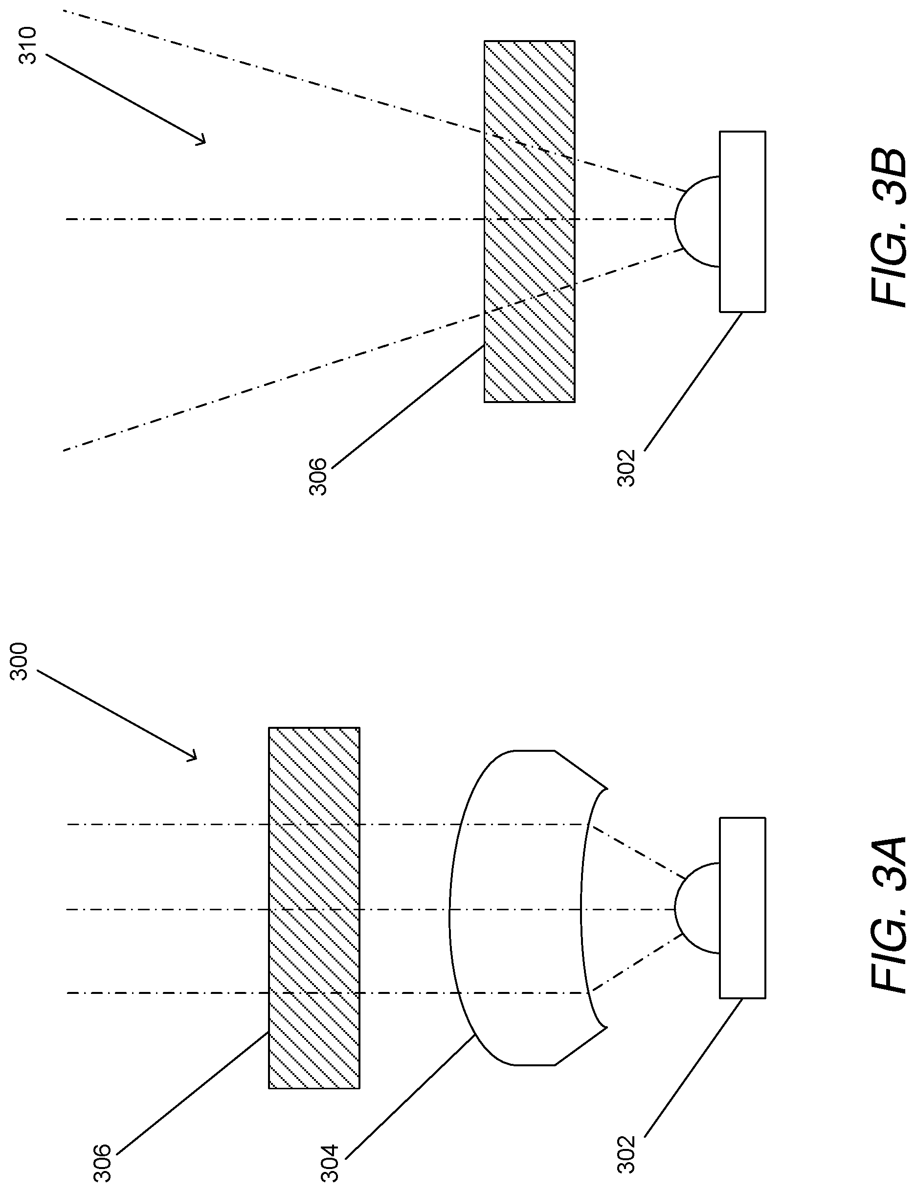
D00013
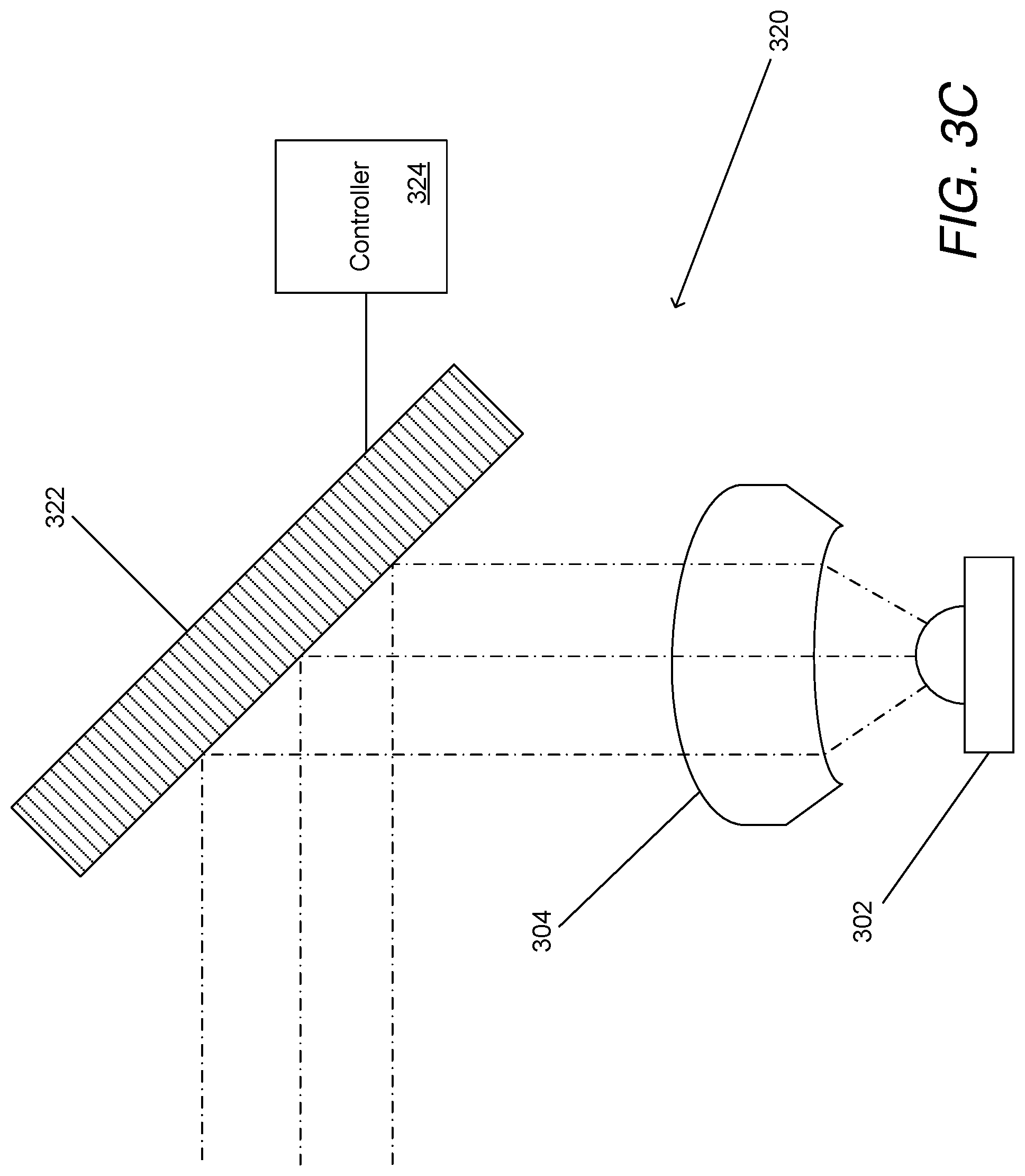
D00014
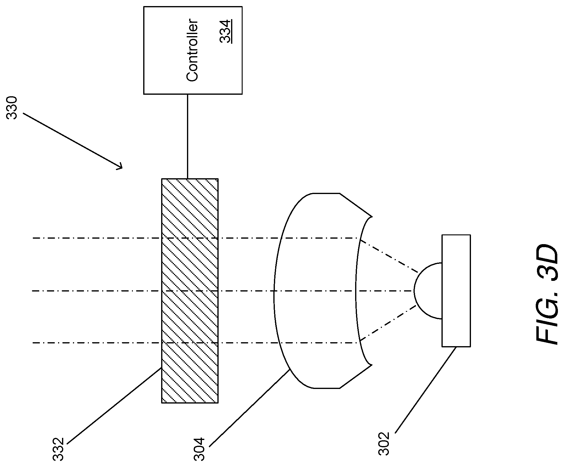
D00015
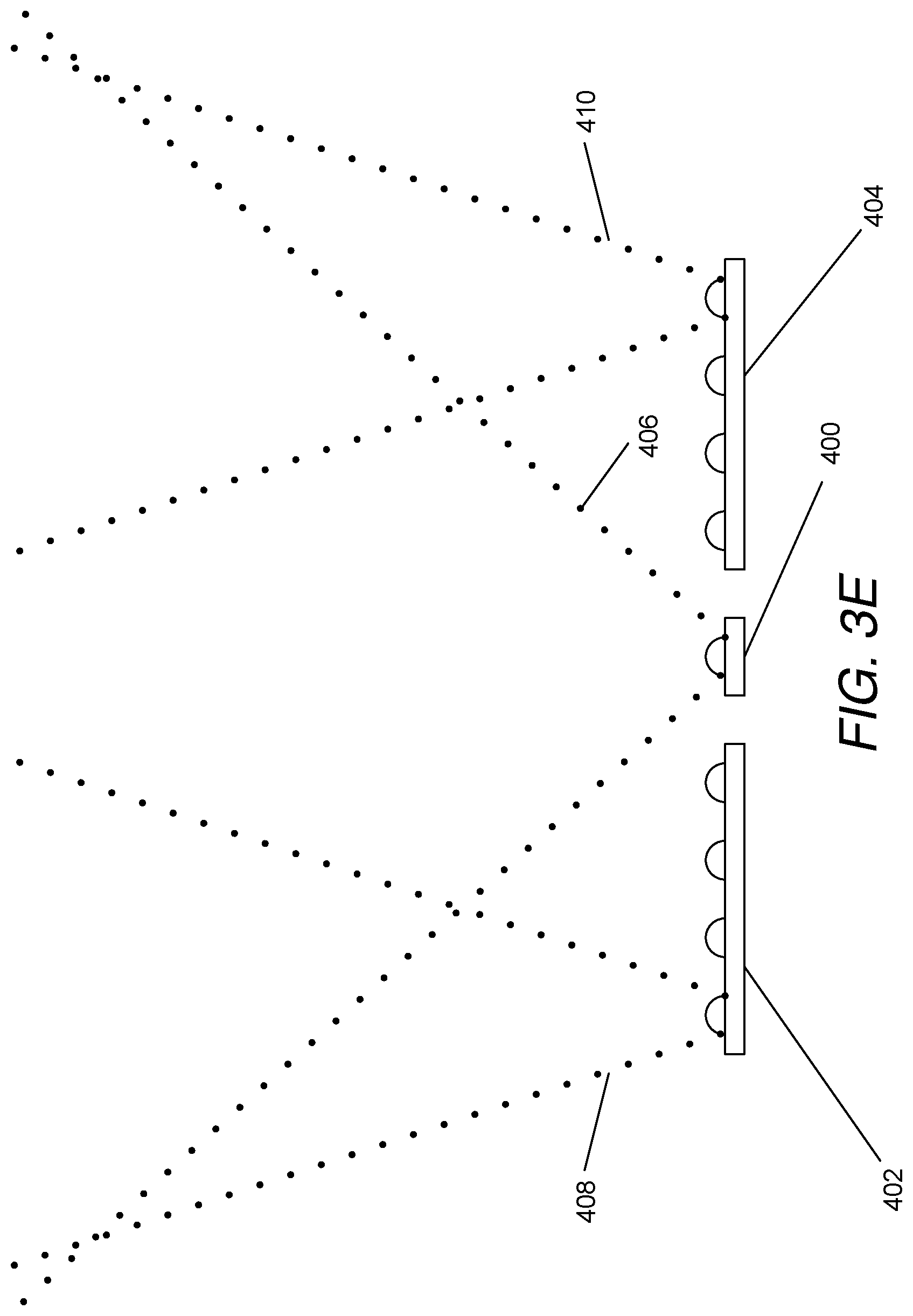
D00016

D00017
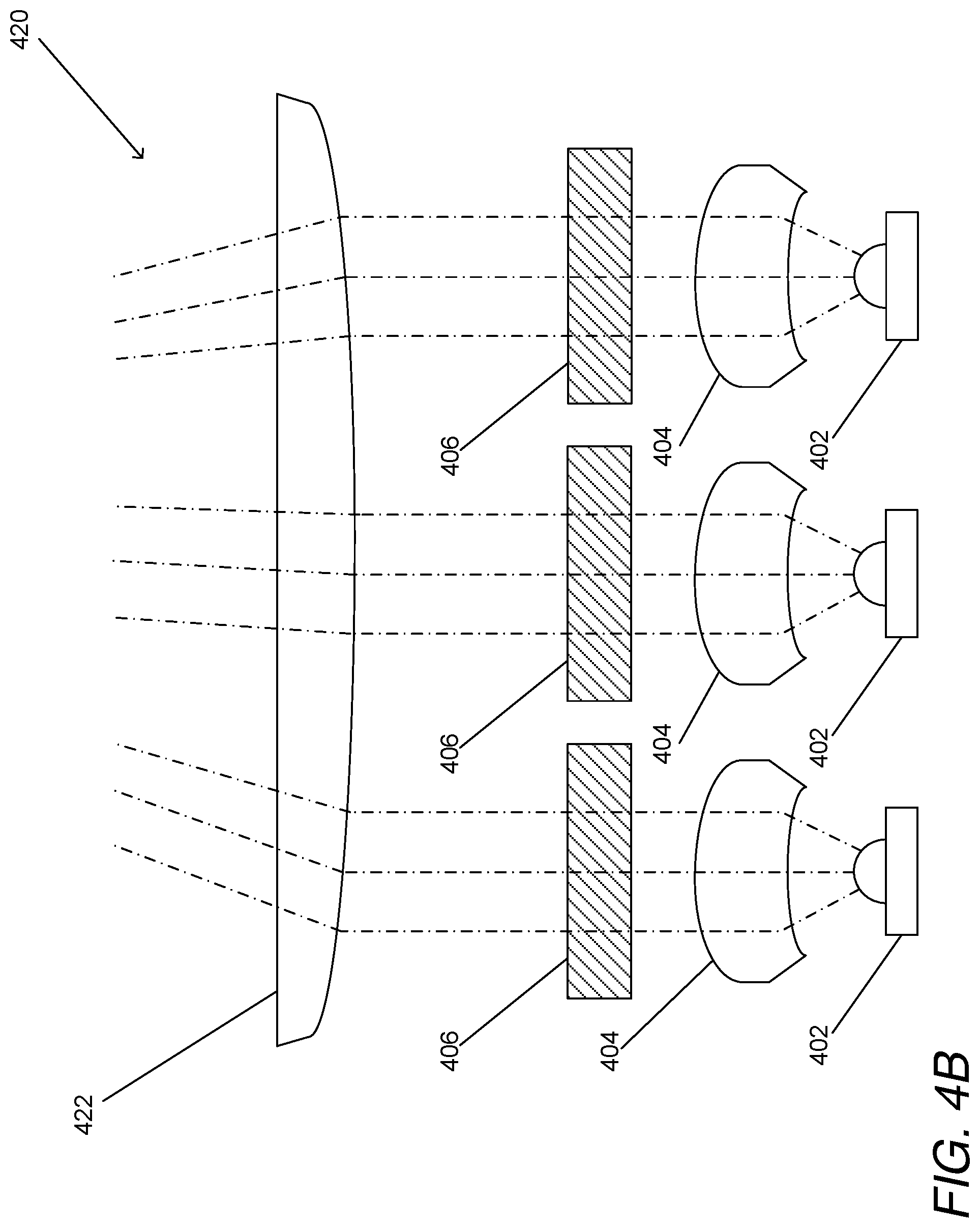
D00018
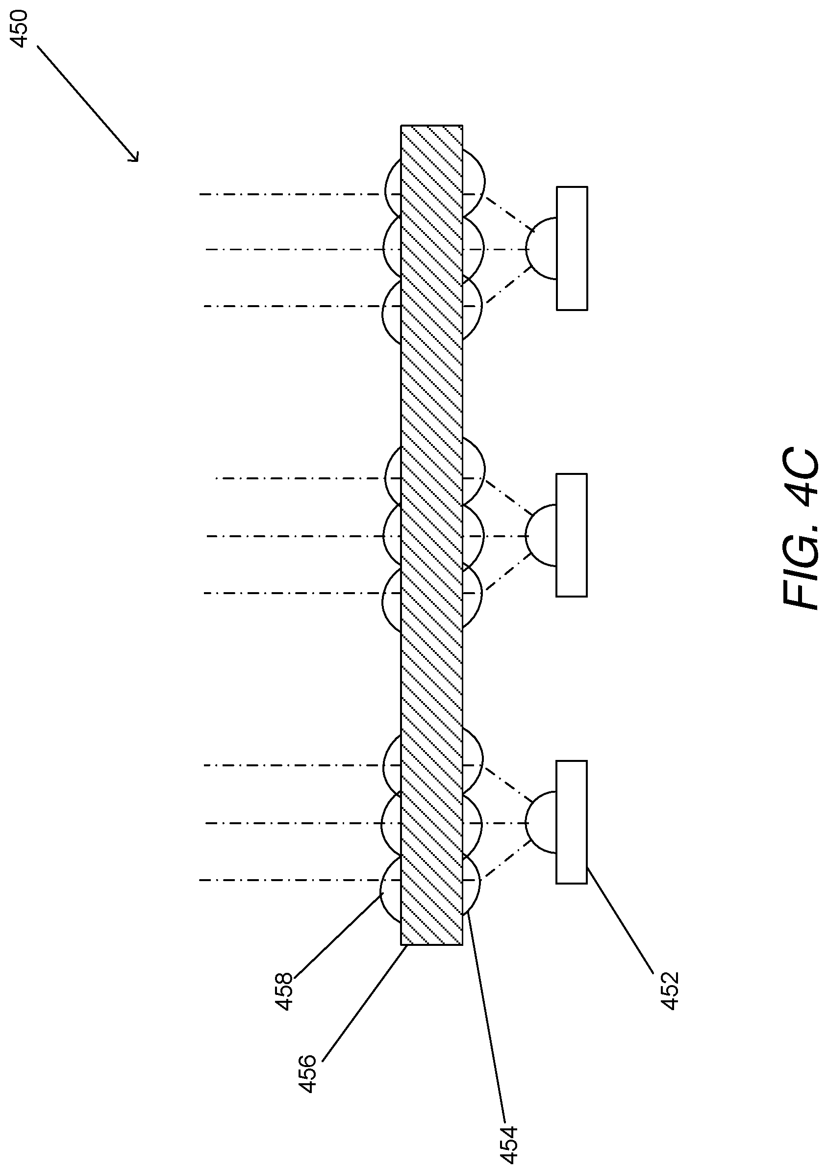
D00019

D00020

D00021

D00022

D00023

D00024
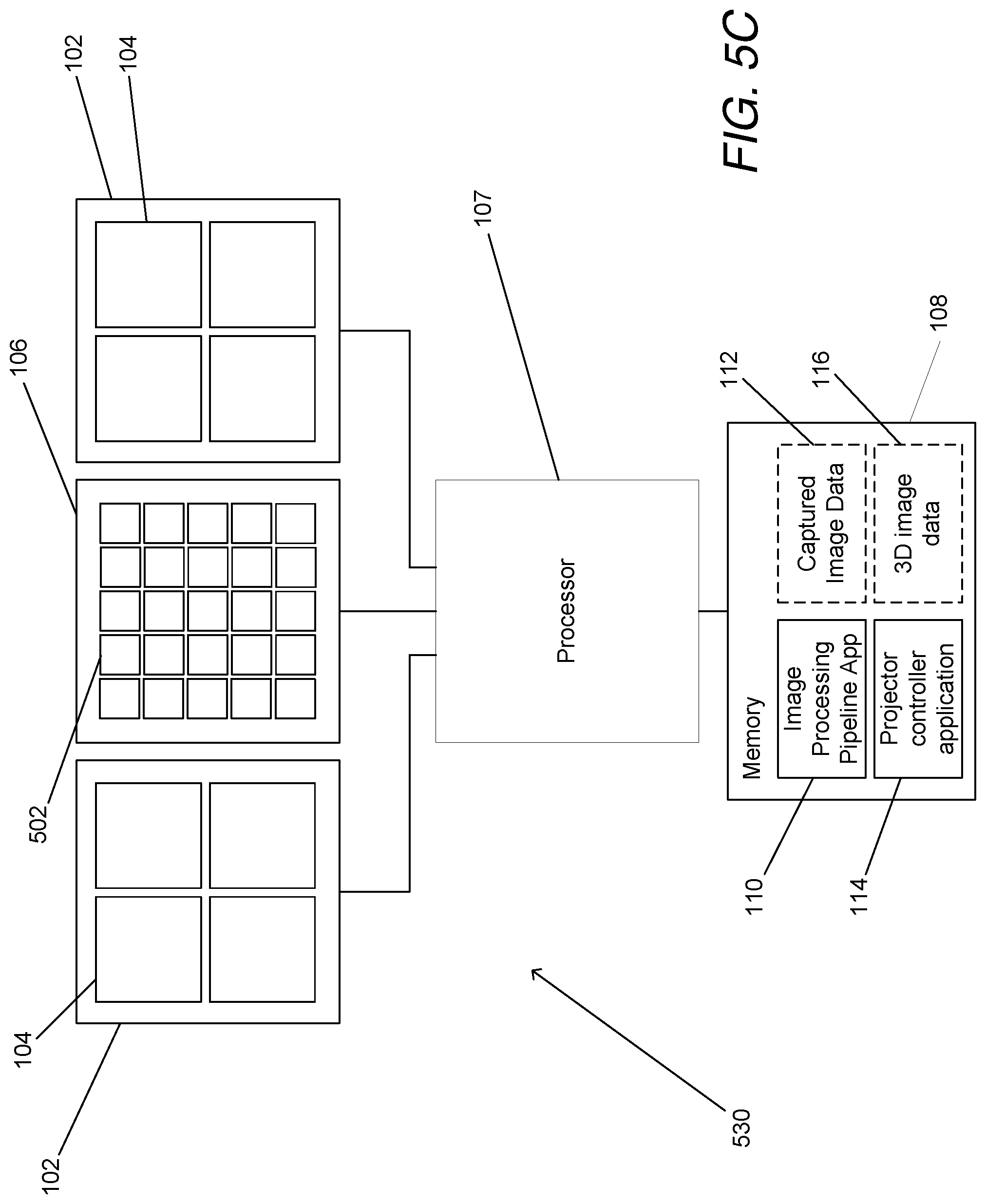
D00025
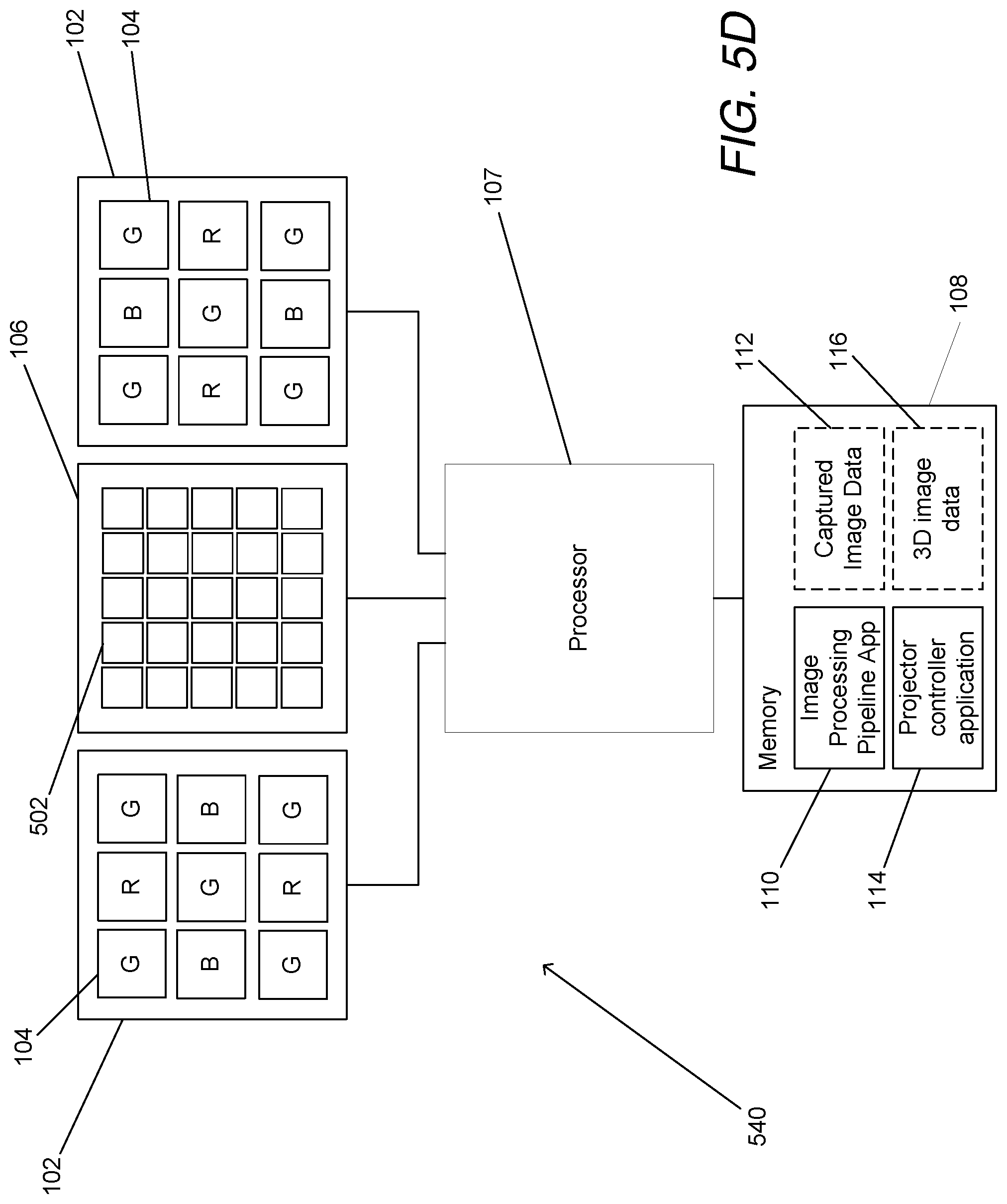
D00026
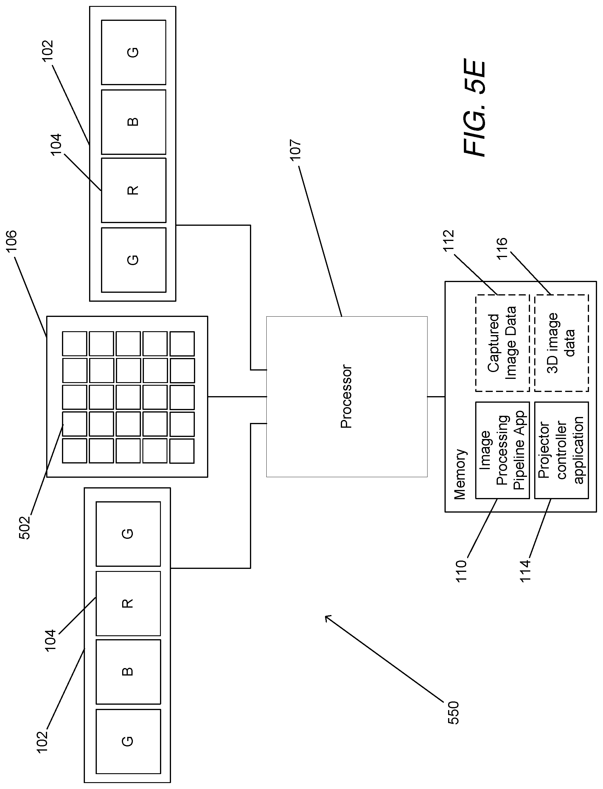
D00027
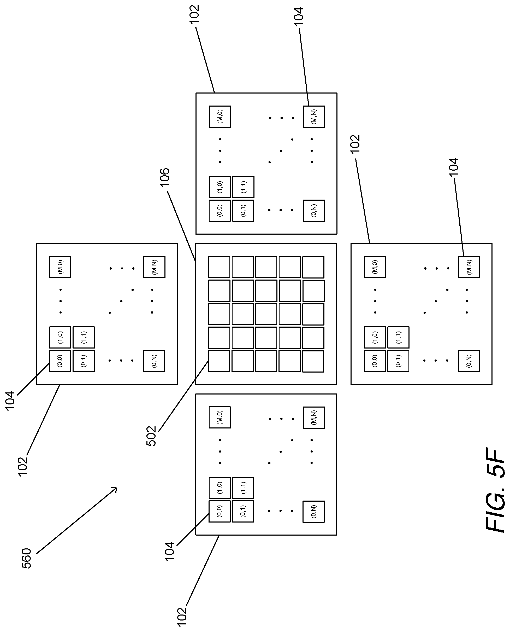
D00028
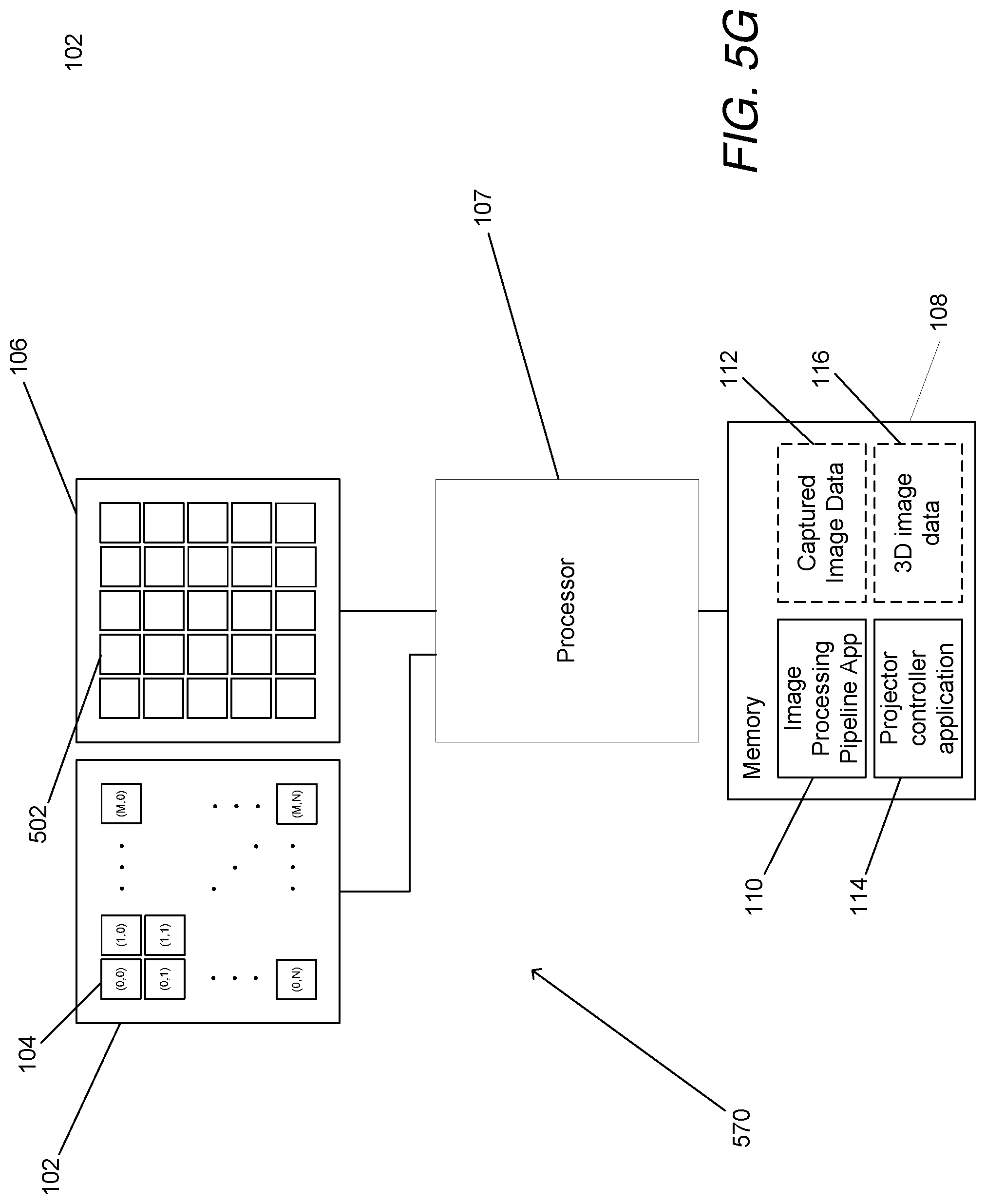
D00029
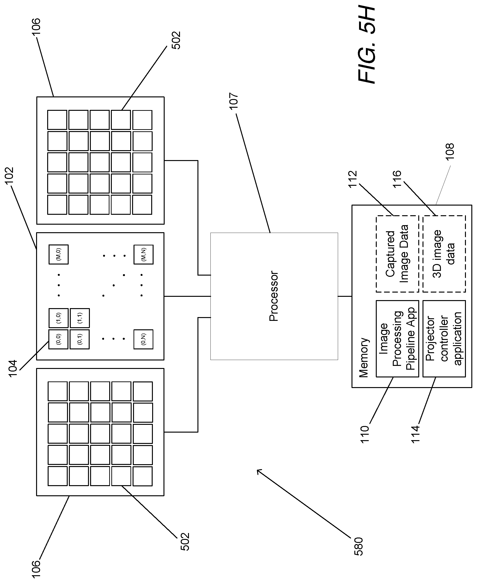
D00030
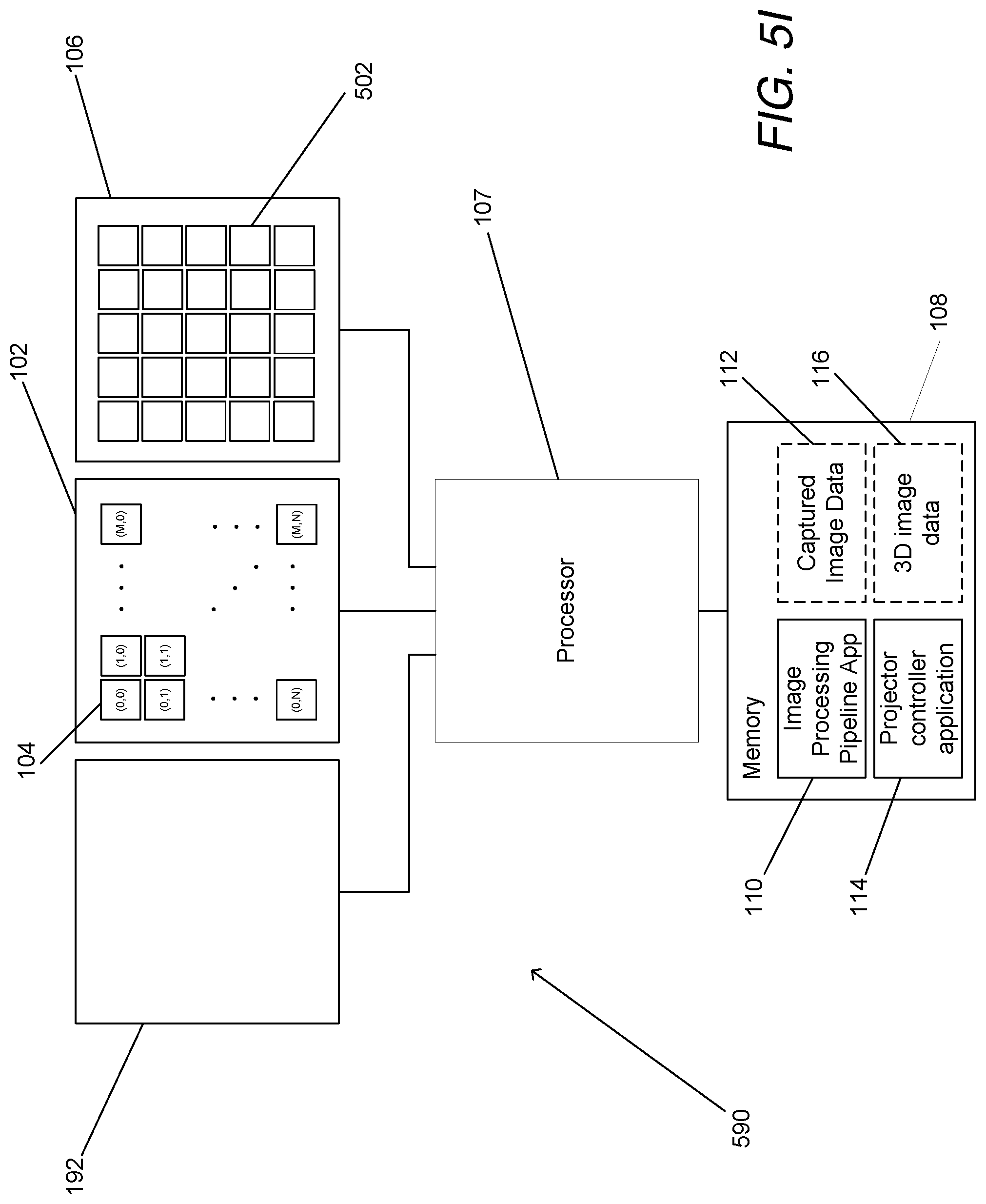
D00031

D00032

XML
uspto.report is an independent third-party trademark research tool that is not affiliated, endorsed, or sponsored by the United States Patent and Trademark Office (USPTO) or any other governmental organization. The information provided by uspto.report is based on publicly available data at the time of writing and is intended for informational purposes only.
While we strive to provide accurate and up-to-date information, we do not guarantee the accuracy, completeness, reliability, or suitability of the information displayed on this site. The use of this site is at your own risk. Any reliance you place on such information is therefore strictly at your own risk.
All official trademark data, including owner information, should be verified by visiting the official USPTO website at www.uspto.gov. This site is not intended to replace professional legal advice and should not be used as a substitute for consulting with a legal professional who is knowledgeable about trademark law.