Implantable medical device with pressure sensor
Kane , et al. Sep
U.S. patent number 10,765,871 [Application Number 15/791,311] was granted by the patent office on 2020-09-08 for implantable medical device with pressure sensor. This patent grant is currently assigned to CARDIAC PACEMAKERS, INC.. The grantee listed for this patent is CARDIAC PACEMAKERS, INC.. Invention is credited to Benjamin J. Haasl, Michael J. Kane, Keith R. Maile.

View All Diagrams
| United States Patent | 10,765,871 |
| Kane , et al. | September 8, 2020 |
Implantable medical device with pressure sensor
Abstract
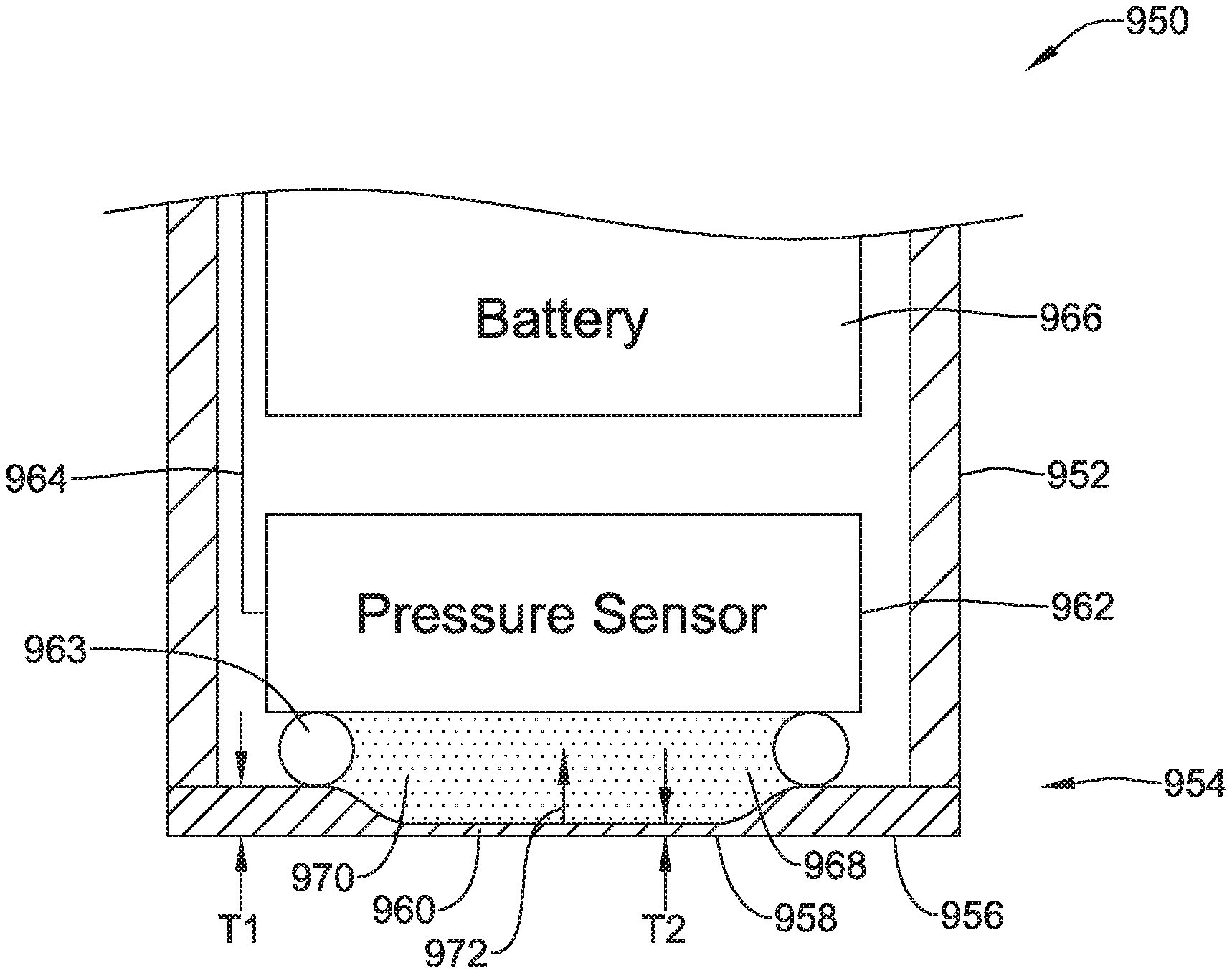
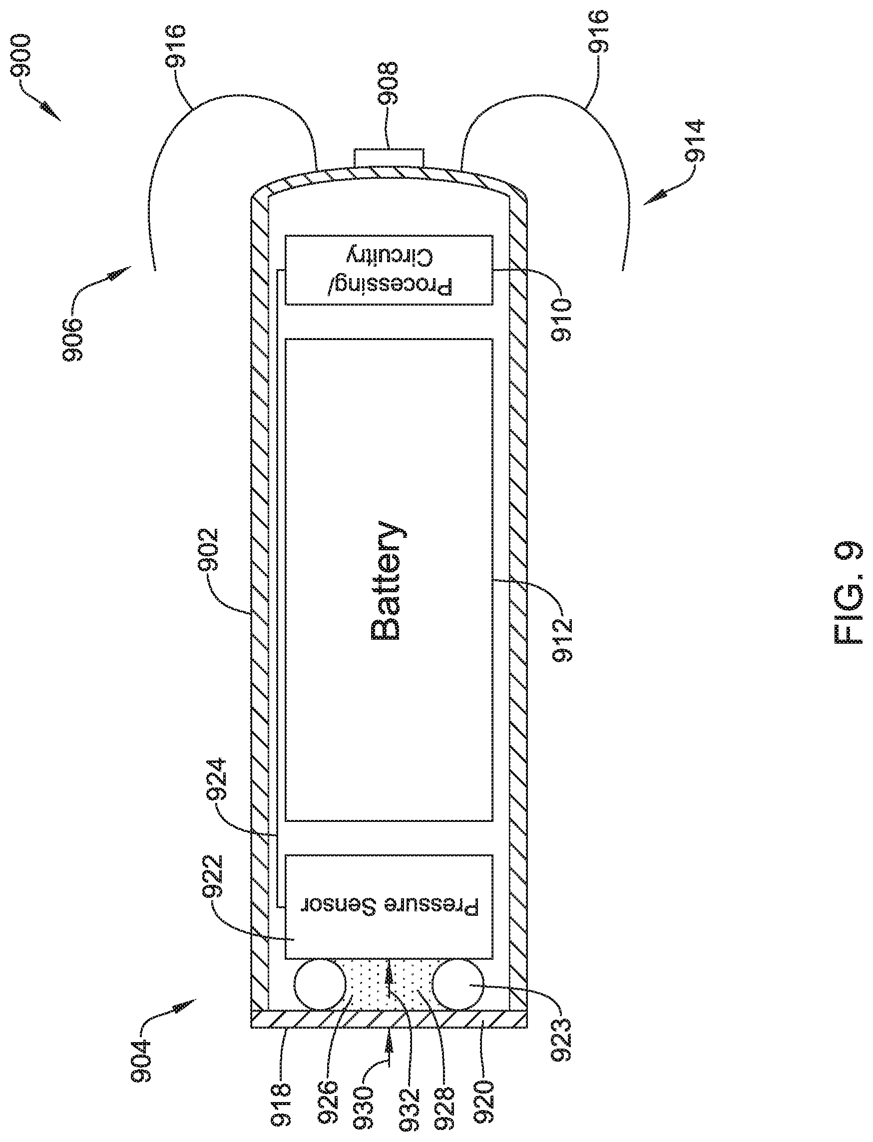
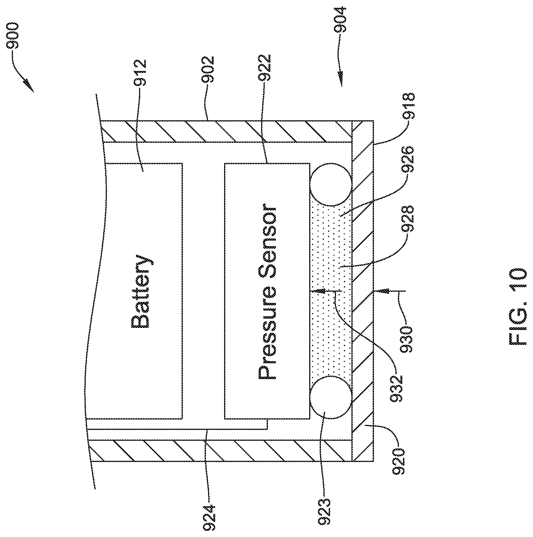
An implantable medical device (IMD) is configured with a pressure sensor. The IMD includes a housing, a pressure sensor and a fluid filled cavity. The housing has a diaphragm that is exposed to the environment outside of the housing. The pressure sensor has a pressure sensor diaphragm that is responsive to a pressure applied to the pressure sensor diaphragm and provides a pressure sensor output signal that is representative of the pressure applied to the pressure sensor diaphragm. The fluid filled cavity is in fluid communication with both the diaphragm of the housing and the pressure sensor diaphragm of the pressure sensor. The fluid filled cavity is configured to communicate a measure related to the pressure applied by the environment to the diaphragm of the housing to the pressure sensor diaphragm of the pressure sensor.
| Inventors: | Kane; Michael J. (St. Paul, MN), Haasl; Benjamin J. (Forest Lake, MN), Maile; Keith R. (New Brighton, MN) | ||||||||||
|---|---|---|---|---|---|---|---|---|---|---|---|
| Applicant: |
|
||||||||||
| Assignee: | CARDIAC PACEMAKERS, INC. (St.
Paul, MN) |
||||||||||
| Family ID: | 1000005040134 | ||||||||||
| Appl. No.: | 15/791,311 | ||||||||||
| Filed: | October 23, 2017 |
Prior Publication Data
| Document Identifier | Publication Date | |
|---|---|---|
| US 20180117341 A1 | May 3, 2018 | |
Related U.S. Patent Documents
| Application Number | Filing Date | Patent Number | Issue Date | ||
|---|---|---|---|---|---|
| 62413766 | Oct 27, 2016 | ||||
| Current U.S. Class: | 1/1 |
| Current CPC Class: | A61N 1/37512 (20170801); A61B 5/0215 (20130101); A61B 5/686 (20130101); A61N 1/3756 (20130101); A61B 5/0422 (20130101); A61B 7/04 (20130101); A61B 5/6882 (20130101); A61B 5/0031 (20130101); A61B 7/00 (20130101); A61B 5/0452 (20130101); A61N 1/3706 (20130101); A61B 5/6869 (20130101); A61N 1/36521 (20130101); A61N 1/36557 (20130101); A61N 1/36564 (20130101); A61N 1/3627 (20130101) |
| Current International Class: | A61B 5/00 (20060101); A61B 7/04 (20060101); A61B 5/0215 (20060101); A61N 1/37 (20060101); A61N 1/375 (20060101); A61B 5/042 (20060101); A61B 7/00 (20060101); A61B 5/0452 (20060101); A61N 1/365 (20060101); A61N 1/362 (20060101) |
| Field of Search: | ;607/18 |
References Cited [Referenced By]
U.S. Patent Documents
| 3835864 | September 1974 | Rasor et al. |
| 3943936 | March 1976 | Rasor et al. |
| 4142530 | March 1979 | Wittkampf |
| 4151513 | April 1979 | Menken et al. |
| 4157720 | June 1979 | Greatbatch |
| RE30366 | August 1980 | Rasor et al. |
| 4243045 | January 1981 | Maas |
| 4250884 | February 1981 | Hartlaub et al. |
| 4256115 | March 1981 | Bilitch |
| 4263919 | April 1981 | Levin |
| 4310000 | January 1982 | Lindemans |
| 4312354 | January 1982 | Walters |
| 4323081 | April 1982 | Wiebusch |
| 4357946 | November 1982 | Dutcher et al. |
| 4365639 | December 1982 | Goldreyer |
| 4440173 | April 1984 | Kludziak et al. |
| 4476868 | October 1984 | Thompson |
| 4522208 | June 1985 | Buffet |
| 4537200 | August 1985 | Widrow |
| 4556063 | December 1985 | Thompson et al. |
| 4562841 | January 1986 | Brockway et al. |
| 4593702 | June 1986 | Kepski et al. |
| 4593955 | June 1986 | Leiber |
| 4630611 | December 1986 | King |
| 4635639 | January 1987 | Hakala et al. |
| 4674508 | June 1987 | DeCote |
| 4712554 | December 1987 | Garson |
| 4729376 | March 1988 | DeCote |
| 4754753 | July 1988 | King |
| 4759366 | July 1988 | Callaghan |
| 4776338 | October 1988 | Lekholm et al. |
| 4787389 | November 1988 | Tarjan |
| 4793353 | December 1988 | Borkan |
| 4819662 | April 1989 | Heil et al. |
| 4858610 | August 1989 | Callaghan et al. |
| 4886064 | December 1989 | Strandberg |
| 4887609 | December 1989 | Cole |
| 4928688 | May 1990 | Mower |
| 4967746 | November 1990 | Vandegriff |
| 4987897 | January 1991 | Funke |
| 4989602 | February 1991 | Sholder et al. |
| 5012806 | May 1991 | De Bellis |
| 5036849 | August 1991 | Hauck et al. |
| 5040534 | August 1991 | Mann et al. |
| 5058581 | October 1991 | Silvian |
| 5078134 | January 1992 | Heilman et al. |
| 5109845 | May 1992 | Yuuchi et al. |
| 5113859 | May 1992 | Funke |
| 5113869 | May 1992 | Nappholz et al. |
| 5117824 | June 1992 | Keimel et al. |
| 5127401 | July 1992 | Grevious et al. |
| 5133353 | July 1992 | Hauser |
| 5144950 | September 1992 | Stoop et al. |
| 5170784 | December 1992 | Ramon et al. |
| 5179945 | January 1993 | Van Hofwegen et al. |
| 5193539 | March 1993 | Schulman et al. |
| 5193540 | March 1993 | Schulman et al. |
| 5241961 | September 1993 | Henry |
| 5243977 | September 1993 | Trabucco et al. |
| 5259387 | November 1993 | DePinto |
| 5269326 | December 1993 | Verrier |
| 5284136 | February 1994 | Hauck et al. |
| 5300107 | April 1994 | Stokes et al. |
| 5301677 | April 1994 | Hsung |
| 5305760 | April 1994 | McKown et al. |
| 5312439 | May 1994 | Loeb |
| 5313953 | May 1994 | Yomtov et al. |
| 5314459 | May 1994 | Swanson et al. |
| 5318597 | June 1994 | Hauck et al. |
| 5324316 | June 1994 | Schulman et al. |
| 5331966 | July 1994 | Bennett et al. |
| 5334222 | August 1994 | Salo et al. |
| 5342408 | August 1994 | deCoriolis et al. |
| 5370667 | December 1994 | Alt |
| 5372606 | December 1994 | Lang et al. |
| 5376106 | December 1994 | Stahmann et al. |
| 5383915 | January 1995 | Adams |
| 5388578 | February 1995 | Yomtov et al. |
| 5404877 | April 1995 | Nolan et al. |
| 5405367 | April 1995 | Schulman et al. |
| 5411031 | May 1995 | Yomtov |
| 5411525 | May 1995 | Swanson et al. |
| 5411535 | May 1995 | Fujii et al. |
| 5456691 | October 1995 | Snell |
| 5458622 | October 1995 | Alt |
| 5466246 | November 1995 | Silvian |
| 5468254 | November 1995 | Hahn et al. |
| 5472453 | December 1995 | Alt |
| 5522866 | June 1996 | Fernald |
| 5540727 | July 1996 | Tockman et al. |
| 5545186 | August 1996 | Olson et al. |
| 5545202 | August 1996 | Dahl et al. |
| 5571146 | November 1996 | Jones et al. |
| 5591214 | January 1997 | Lu |
| 5620466 | April 1997 | Haefner et al. |
| 5634938 | June 1997 | Swanson et al. |
| 5649968 | July 1997 | Alt et al. |
| 5662688 | September 1997 | Haefner et al. |
| 5674259 | October 1997 | Gray |
| 5683426 | November 1997 | Greenhut et al. |
| 5683432 | November 1997 | Goedeke et al. |
| 5702427 | December 1997 | Ecker et al. |
| 5706823 | January 1998 | Wodlinger |
| 5709215 | January 1998 | Perttu et al. |
| 5720770 | February 1998 | Nappholz et al. |
| 5728154 | March 1998 | Crossett et al. |
| 5741314 | April 1998 | Daly et al. |
| 5741315 | April 1998 | Lee et al. |
| 5752976 | May 1998 | Duffin et al. |
| 5752977 | May 1998 | Grevious et al. |
| 5755736 | May 1998 | Gillberg et al. |
| 5759199 | June 1998 | Snell et al. |
| 5774501 | June 1998 | Halpern et al. |
| 5792195 | August 1998 | Carlson et al. |
| 5792202 | August 1998 | Rueter |
| 5792203 | August 1998 | Schroeppel |
| 5792205 | August 1998 | Alt et al. |
| 5792208 | August 1998 | Gray |
| 5814089 | September 1998 | Stokes et al. |
| 5827216 | October 1998 | Igo et al. |
| 5836985 | November 1998 | Rostami et al. |
| 5836987 | November 1998 | Baumann et al. |
| 5842977 | December 1998 | Lesho et al. |
| 5855593 | January 1999 | Olson et al. |
| 5873894 | February 1999 | Vandegriff et al. |
| 5891184 | April 1999 | Lee et al. |
| 5897586 | April 1999 | Molina |
| 5899876 | May 1999 | Flower |
| 5899928 | May 1999 | Sholder et al. |
| 5919214 | July 1999 | Ciciarelli et al. |
| 5935078 | August 1999 | Feierbach |
| 5941906 | August 1999 | Barreras, Sr. et al. |
| 5944744 | August 1999 | Paul et al. |
| 5954757 | September 1999 | Gray |
| 5978713 | November 1999 | Prutchi et al. |
| 5991660 | November 1999 | Goyal |
| 5991661 | November 1999 | Park et al. |
| 5999848 | December 1999 | Gord et al. |
| 5999857 | December 1999 | Weijand et al. |
| 6016445 | January 2000 | Baura |
| 6026320 | February 2000 | Carlson et al. |
| 6029085 | February 2000 | Olson et al. |
| 6041250 | March 2000 | DePinto |
| 6044298 | March 2000 | Salo et al. |
| 6044300 | March 2000 | Gray |
| 6055454 | April 2000 | Heemels |
| 6073050 | June 2000 | Griffith |
| 6076016 | June 2000 | Feierbach |
| 6077236 | June 2000 | Cunningham |
| 6080187 | June 2000 | Alt et al. |
| 6083248 | July 2000 | Thompson |
| 6106551 | August 2000 | Crossett et al. |
| 6115636 | September 2000 | Ryan |
| 6128526 | October 2000 | Stadler et al. |
| 6141581 | October 2000 | Olson et al. |
| 6141588 | October 2000 | Cox et al. |
| 6141592 | October 2000 | Pauly |
| 6144879 | November 2000 | Gray |
| 6162195 | December 2000 | Igo et al. |
| 6164284 | December 2000 | Schulman et al. |
| 6167310 | December 2000 | Grevious |
| 6201993 | March 2001 | Kruse et al. |
| 6208894 | March 2001 | Schulman et al. |
| 6211799 | April 2001 | Post et al. |
| 6221011 | April 2001 | Bardy |
| 6240316 | May 2001 | Richmond et al. |
| 6240317 | May 2001 | Villaseca et al. |
| 6256534 | July 2001 | Dahl |
| 6259947 | July 2001 | Olson et al. |
| 6266558 | July 2001 | Gozani et al. |
| 6266567 | July 2001 | Ishikawa et al. |
| 6270457 | August 2001 | Bardy |
| 6272377 | August 2001 | Sweeney et al. |
| 6273856 | August 2001 | Sun et al. |
| 6277072 | August 2001 | Bardy |
| 6280380 | August 2001 | Bardy |
| 6285907 | September 2001 | Kramer et al. |
| 6292698 | September 2001 | Duffin et al. |
| 6295473 | September 2001 | Rosar |
| 6297943 | October 2001 | Carson |
| 6298271 | October 2001 | Weijand |
| 6307751 | October 2001 | Bodony et al. |
| 6312378 | November 2001 | Bardy |
| 6314323 | November 2001 | Ekwall |
| 6315721 | November 2001 | Schulman et al. |
| 6336903 | January 2002 | Bardy |
| 6345202 | February 2002 | Richmond et al. |
| 6351667 | February 2002 | Godie |
| 6351669 | February 2002 | Hartley et al. |
| 6353759 | March 2002 | Hartley et al. |
| 6358203 | March 2002 | Bardy |
| 6361780 | March 2002 | Ley et al. |
| 6368284 | April 2002 | Bardy |
| 6371922 | April 2002 | Baumann et al. |
| 6398728 | June 2002 | Bardy |
| 6398738 | June 2002 | Millar |
| 6400982 | June 2002 | Sweeney et al. |
| 6400990 | June 2002 | Silvian |
| 6408208 | June 2002 | Sun |
| 6409674 | June 2002 | Brockway et al. |
| 6411848 | June 2002 | Kramer et al. |
| 6424865 | July 2002 | Ding |
| 6434429 | August 2002 | Kraus et al. |
| 6438410 | August 2002 | Hsu et al. |
| 6438417 | August 2002 | Rockwell et al. |
| 6438421 | August 2002 | Stahmann et al. |
| 6440066 | August 2002 | Bardy |
| 6441747 | August 2002 | Khair et al. |
| 6442426 | August 2002 | Kroll |
| 6442432 | August 2002 | Lee |
| 6443891 | September 2002 | Grevious |
| 6445953 | September 2002 | Bulkes et al. |
| 6453200 | September 2002 | Koslar |
| 6459929 | October 2002 | Hopper et al. |
| 6470215 | October 2002 | Kraus et al. |
| 6471645 | October 2002 | Warkentin et al. |
| 6480745 | November 2002 | Nelson et al. |
| 6487443 | November 2002 | Olson et al. |
| 6490487 | December 2002 | Kraus et al. |
| 6498951 | December 2002 | Larson et al. |
| 6507755 | January 2003 | Gozani et al. |
| 6507759 | January 2003 | Prutchi et al. |
| 6512940 | January 2003 | Brabec et al. |
| 6522915 | February 2003 | Ceballos et al. |
| 6526311 | February 2003 | Begemann |
| 6539253 | March 2003 | Thompson et al. |
| 6542775 | April 2003 | Ding et al. |
| 6553258 | April 2003 | Stahmann et al. |
| 6561975 | May 2003 | Pool et al. |
| 6564807 | May 2003 | Schulman et al. |
| 6574506 | June 2003 | Kramer et al. |
| 6584351 | June 2003 | Ekwall |
| 6584352 | June 2003 | Combs et al. |
| 6597948 | July 2003 | Rockwell et al. |
| 6597951 | July 2003 | Kramer et al. |
| 6622046 | September 2003 | Fraley et al. |
| 6628985 | September 2003 | Sweeney et al. |
| 6647292 | November 2003 | Bardy et al. |
| 6666844 | December 2003 | Igo et al. |
| 6689117 | February 2004 | Sweeney et al. |
| 6690959 | February 2004 | Thompson |
| 6694189 | February 2004 | Begemann |
| 6704602 | March 2004 | Berg et al. |
| 6718212 | April 2004 | Parry et al. |
| 6721597 | April 2004 | Bardy et al. |
| 6738670 | May 2004 | Almendinger et al. |
| 6746797 | June 2004 | Benson et al. |
| 6749566 | June 2004 | Russ |
| 6758810 | July 2004 | Lebel et al. |
| 6763269 | July 2004 | Cox |
| 6778860 | August 2004 | Ostroff et al. |
| 6788971 | September 2004 | Sloman et al. |
| 6788974 | September 2004 | Bardy et al. |
| 6804558 | October 2004 | Haller et al. |
| 6807442 | October 2004 | Myklebust et al. |
| 6847844 | January 2005 | Sun et al. |
| 6871088 | March 2005 | Chinchoy |
| 6871095 | March 2005 | Stahmann et al. |
| 6878112 | April 2005 | Linberg et al. |
| 6885889 | April 2005 | Chinchoy |
| 6892094 | May 2005 | Ousdigian et al. |
| 6897788 | May 2005 | Khair et al. |
| 6904315 | June 2005 | Panken et al. |
| 6922592 | July 2005 | Thompson et al. |
| 6931282 | August 2005 | Esler |
| 6934585 | August 2005 | Schloss et al. |
| 6957107 | October 2005 | Rogers et al. |
| 6978176 | December 2005 | Lattouf |
| 6985773 | January 2006 | Von Arx et al. |
| 6990375 | January 2006 | Kloss et al. |
| 7001366 | February 2006 | Ballard |
| 7003350 | February 2006 | Denker et al. |
| 7006864 | February 2006 | Echt et al. |
| 7013178 | March 2006 | Reinke et al. |
| 7027871 | April 2006 | Burnes et al. |
| 7050849 | May 2006 | Echt et al. |
| 7060031 | June 2006 | Webb et al. |
| 7063693 | June 2006 | Guenst |
| 7082336 | July 2006 | Ransbury et al. |
| 7085606 | August 2006 | Flach et al. |
| 7092758 | August 2006 | Sun et al. |
| 7110824 | September 2006 | Amundson et al. |
| 7120504 | October 2006 | Osypka |
| 7130681 | October 2006 | Gebhardt et al. |
| 7139613 | November 2006 | Reinke et al. |
| 7142912 | November 2006 | Wagner et al. |
| 7142917 | November 2006 | Fukui |
| 7146225 | December 2006 | Guenst et al. |
| 7146226 | December 2006 | Lau et al. |
| 7149575 | December 2006 | Ostroff et al. |
| 7149581 | December 2006 | Goedeke |
| 7149588 | December 2006 | Lau et al. |
| 7158839 | January 2007 | Lau |
| 7162307 | January 2007 | Patrias |
| 7164952 | January 2007 | Lau et al. |
| 7177700 | February 2007 | Cox |
| 7181505 | February 2007 | Haller et al. |
| 7184830 | February 2007 | Echt et al. |
| 7186214 | March 2007 | Ness |
| 7189204 | March 2007 | Ni et al. |
| 7191015 | March 2007 | Lamson et al. |
| 7200437 | April 2007 | Nabutovsky et al. |
| 7200439 | April 2007 | Zdeblick et al. |
| 7206423 | April 2007 | Feng et al. |
| 7209785 | April 2007 | Kim et al. |
| 7209790 | April 2007 | Thompson et al. |
| 7211884 | May 2007 | Davis et al. |
| 7212861 | May 2007 | Park et al. |
| 7212871 | May 2007 | Morgan |
| 7226440 | June 2007 | Gelfand et al. |
| 7228183 | June 2007 | Sun et al. |
| 7236821 | June 2007 | Cates et al. |
| 7236829 | June 2007 | Farazi et al. |
| 7254448 | August 2007 | Almendinger et al. |
| 7260436 | August 2007 | Kilgore et al. |
| 7270669 | September 2007 | Sra |
| 7272448 | September 2007 | Morgan et al. |
| 7277755 | October 2007 | Falkenberg et al. |
| 7280872 | October 2007 | Mosesov et al. |
| 7286875 | October 2007 | Park et al. |
| 7288096 | October 2007 | Chin |
| 7289847 | October 2007 | Gill et al. |
| 7289852 | October 2007 | Helfinstine et al. |
| 7289853 | October 2007 | Campbell et al. |
| 7289855 | October 2007 | Nghiem et al. |
| 7302294 | November 2007 | Kamath et al. |
| 7305266 | December 2007 | Kroll |
| 7310556 | December 2007 | Bulkes |
| 7319905 | January 2008 | Morgan et al. |
| 7321798 | January 2008 | Muhlenberg et al. |
| 7333853 | February 2008 | Mazar et al. |
| 7336994 | February 2008 | Hettrick et al. |
| 7347819 | March 2008 | Lebel et al. |
| 7366572 | April 2008 | Heruth et al. |
| 7373207 | May 2008 | Lattouf |
| 7376458 | May 2008 | Palreddy et al. |
| 7384403 | June 2008 | Sherman |
| 7386342 | June 2008 | Falkenberg et al. |
| 7392090 | June 2008 | Sweeney et al. |
| 7406105 | July 2008 | DelMain et al. |
| 7406349 | July 2008 | Seeberger et al. |
| 7410497 | August 2008 | Hastings et al. |
| 7418868 | September 2008 | Karicherla et al. |
| 7425200 | September 2008 | Brockway et al. |
| 7433739 | October 2008 | Salys et al. |
| 7477935 | January 2009 | Palreddy et al. |
| 7496409 | February 2009 | Greenhut et al. |
| 7496410 | February 2009 | Heil |
| 7502652 | March 2009 | Gaunt et al. |
| 7512448 | March 2009 | Malick et al. |
| 7515969 | April 2009 | Tockman et al. |
| 7526342 | April 2009 | Chin et al. |
| 7529589 | May 2009 | Williams et al. |
| 7532933 | May 2009 | Hastings et al. |
| 7536222 | May 2009 | Bardy et al. |
| 7536224 | May 2009 | Ritscher et al. |
| 7539541 | May 2009 | Quiles et al. |
| 7544197 | June 2009 | Kelsch et al. |
| 7558631 | July 2009 | Cowan et al. |
| 7565195 | July 2009 | Kroll et al. |
| 7580746 | August 2009 | Gilkerson et al. |
| 7584002 | September 2009 | Burnes et al. |
| 7590455 | September 2009 | Heruth et al. |
| 7596412 | September 2009 | Kroll |
| 7606621 | October 2009 | Brisken et al. |
| 7610088 | October 2009 | Chinchoy |
| 7610092 | October 2009 | Cowan et al. |
| 7610099 | October 2009 | Almendinger et al. |
| 7610104 | October 2009 | Kaplan et al. |
| 7616991 | November 2009 | Mann et al. |
| 7617001 | November 2009 | Penner et al. |
| 7617007 | November 2009 | Williams et al. |
| 7630763 | December 2009 | Kwok et al. |
| 7630767 | December 2009 | Poore et al. |
| 7634313 | December 2009 | Kroll et al. |
| 7637867 | December 2009 | Zdeblick |
| 7640060 | December 2009 | Zdeblick |
| 7647109 | January 2010 | Hastings et al. |
| 7650186 | January 2010 | Hastings et al. |
| 7657311 | February 2010 | Bardy et al. |
| 7668596 | February 2010 | Von Arx et al. |
| 7676266 | March 2010 | Kroll |
| 7682316 | March 2010 | Anderson et al. |
| 7691047 | April 2010 | Ferrari |
| 7702389 | April 2010 | Czygan et al. |
| 7702392 | April 2010 | Echt et al. |
| 7713194 | May 2010 | Zdeblick |
| 7713195 | May 2010 | Zdeblick |
| 7729783 | June 2010 | Michels et al. |
| 7734333 | June 2010 | Ghanem et al. |
| 7734343 | June 2010 | Ransbury et al. |
| 7738958 | June 2010 | Zdeblick et al. |
| 7738964 | June 2010 | Von Arx et al. |
| 7742812 | June 2010 | Ghanem et al. |
| 7742816 | June 2010 | Masoud et al. |
| 7742822 | June 2010 | Masoud et al. |
| 7743151 | June 2010 | Vallapureddy et al. |
| 7747335 | June 2010 | Williams |
| 7751881 | July 2010 | Cowan et al. |
| 7758521 | July 2010 | Morris et al. |
| 7761150 | July 2010 | Ghanem et al. |
| 7761164 | July 2010 | Verhoef et al. |
| 7765001 | July 2010 | Echt et al. |
| 7769452 | August 2010 | Ghanem et al. |
| 7783340 | August 2010 | Sanghera et al. |
| 7783362 | August 2010 | Whitehurst et al. |
| 7792588 | September 2010 | Harding |
| 7797059 | September 2010 | Bornzin et al. |
| 7801596 | September 2010 | Fischell et al. |
| 7809438 | October 2010 | Echt et al. |
| 7809441 | October 2010 | Kane et al. |
| 7840281 | November 2010 | Kveen et al. |
| 7844331 | November 2010 | Li et al. |
| 7844348 | November 2010 | Swoyer et al. |
| 7846088 | December 2010 | Ness |
| 7848815 | December 2010 | Brisken et al. |
| 7848823 | December 2010 | Drasler et al. |
| 7860455 | December 2010 | Fukumoto et al. |
| 7871433 | January 2011 | Lattouf |
| 7877136 | January 2011 | Moffitt et al. |
| 7877142 | January 2011 | Moaddeb et al. |
| 7881786 | February 2011 | Jackson |
| 7881798 | February 2011 | Miesel et al. |
| 7881810 | February 2011 | Chitre et al. |
| 7890173 | February 2011 | Brisken et al. |
| 7890181 | February 2011 | Denzene et al. |
| 7890192 | February 2011 | Kelsch et al. |
| 7894885 | February 2011 | Bartal et al. |
| 7894894 | February 2011 | Stadler et al. |
| 7894907 | February 2011 | Cowan et al. |
| 7894910 | February 2011 | Cowan et al. |
| 7894915 | February 2011 | Chitre et al. |
| 7899537 | March 2011 | Kroll et al. |
| 7899541 | March 2011 | Cowan et al. |
| 7899542 | March 2011 | Cowan et al. |
| 7899554 | March 2011 | Williams et al. |
| 7901360 | March 2011 | Yang et al. |
| 7904170 | March 2011 | Harding |
| 7907993 | March 2011 | Ghanem et al. |
| 7920928 | April 2011 | Yang et al. |
| 7925343 | April 2011 | Min et al. |
| 7930022 | April 2011 | Zhang et al. |
| 7930040 | April 2011 | Kelsch et al. |
| 7937135 | May 2011 | Ghanem et al. |
| 7937148 | May 2011 | Jacobson |
| 7937161 | May 2011 | Hastings et al. |
| 7941214 | May 2011 | Kleckner et al. |
| 7945333 | May 2011 | Jacobson |
| 7946997 | May 2011 | Hubinette |
| 7949404 | May 2011 | Hill |
| 7949405 | May 2011 | Feher |
| 7953486 | May 2011 | Daum et al. |
| 7953493 | May 2011 | Fowler et al. |
| 7962202 | June 2011 | Bhunia |
| 7974702 | July 2011 | Fain et al. |
| 7979136 | July 2011 | Young et al. |
| 7983753 | July 2011 | Severin |
| 7991467 | August 2011 | Markowitz et al. |
| 7991471 | August 2011 | Ghanem et al. |
| 7996087 | August 2011 | Cowan et al. |
| 8000791 | August 2011 | Sunagawa et al. |
| 8000807 | August 2011 | Morris et al. |
| 8001975 | August 2011 | DiSilvestro et al. |
| 8002700 | August 2011 | Ferek-Petric et al. |
| 8010209 | August 2011 | Jacobson |
| 8019419 | September 2011 | Panescu et al. |
| 8019434 | September 2011 | Quiles et al. |
| 8027727 | September 2011 | Freeberg |
| 8027729 | September 2011 | Sunagawa et al. |
| 8032219 | October 2011 | Neumann et al. |
| 8036743 | October 2011 | Savage et al. |
| 8046079 | October 2011 | Bange et al. |
| 8046080 | October 2011 | Von Arx et al. |
| 8050297 | November 2011 | DelMain et al. |
| 8050759 | November 2011 | Stegemann et al. |
| 8050774 | November 2011 | Kveen et al. |
| 8055345 | November 2011 | Li et al. |
| 8055350 | November 2011 | Roberts |
| 8060212 | November 2011 | Rios et al. |
| 8065018 | November 2011 | Haubrich et al. |
| 8073542 | December 2011 | Doerr |
| 8078278 | December 2011 | Penner |
| 8078283 | December 2011 | Cowan et al. |
| 8079959 | December 2011 | Sanghera et al. |
| 8095123 | January 2012 | Gray |
| 8102789 | January 2012 | Rosar et al. |
| 8103359 | January 2012 | Reddy |
| 8103361 | January 2012 | Moser |
| 8112148 | February 2012 | Giftakis et al. |
| 8114021 | February 2012 | Robertson et al. |
| 8116867 | February 2012 | Ostroff |
| 8121680 | February 2012 | Falkenberg et al. |
| 8123684 | February 2012 | Zdeblick |
| 8126545 | February 2012 | Flach et al. |
| 8131334 | March 2012 | Lu et al. |
| 8140161 | March 2012 | Willerton et al. |
| 8150521 | April 2012 | Crowley et al. |
| 8157813 | April 2012 | Ko et al. |
| 8160672 | April 2012 | Kim et al. |
| 8160702 | April 2012 | Mann et al. |
| 8160704 | April 2012 | Freeberg |
| 8165694 | April 2012 | Carbanaru et al. |
| 8175715 | May 2012 | Cox |
| 8180451 | May 2012 | Hickman et al. |
| 8185213 | May 2012 | Kveen et al. |
| 8187161 | May 2012 | Li et al. |
| 8195293 | June 2012 | Limousin et al. |
| 8195308 | June 2012 | Frank et al. |
| 8200341 | June 2012 | Sanghera et al. |
| 8204595 | June 2012 | Pianca et al. |
| 8204605 | June 2012 | Hastings et al. |
| 8209014 | June 2012 | Doerr |
| 8214043 | July 2012 | Matos |
| 8224244 | July 2012 | Kim et al. |
| 8229556 | July 2012 | Li |
| 8233985 | July 2012 | Bulkes et al. |
| 8262578 | September 2012 | Bharmi et al. |
| 8265748 | September 2012 | Liu et al. |
| 8265757 | September 2012 | Mass et al. |
| 8280521 | October 2012 | Haubrich et al. |
| 8285387 | October 2012 | Utsi et al. |
| 8290598 | October 2012 | Boon et al. |
| 8290600 | October 2012 | Hastings et al. |
| 8295939 | October 2012 | Jacobson |
| 8301254 | October 2012 | Mosesov et al. |
| 8306621 | November 2012 | Kim et al. |
| 8315701 | November 2012 | Cowan et al. |
| 8315708 | November 2012 | Berthelsdorf et al. |
| 8321021 | November 2012 | Kisker et al. |
| 8321036 | November 2012 | Brockway et al. |
| 8332034 | December 2012 | Patangay et al. |
| 8332036 | December 2012 | Hastings et al. |
| 8335563 | December 2012 | Stessman |
| 8335568 | December 2012 | Heruth et al. |
| 8340750 | December 2012 | Prakash et al. |
| 8340780 | December 2012 | Hastings et al. |
| 8352025 | January 2013 | Jacobson |
| 8352028 | January 2013 | Wenger |
| 8352038 | January 2013 | Mao et al. |
| 8359098 | January 2013 | Lund et al. |
| 8364261 | January 2013 | Stubbs et al. |
| 8364276 | January 2013 | Willis |
| 8369959 | February 2013 | Meskens |
| 8369962 | February 2013 | Abrahamson |
| 8380320 | February 2013 | Spital |
| 8386051 | February 2013 | Rys |
| 8391981 | March 2013 | Mosesov |
| 8391990 | March 2013 | Smith et al. |
| 8406874 | March 2013 | Liu et al. |
| 8406879 | March 2013 | Shuros et al. |
| 8406886 | March 2013 | Gaunt et al. |
| 8412352 | April 2013 | Griswold et al. |
| 8417340 | April 2013 | Goossen |
| 8417341 | April 2013 | Freeberg |
| 8423149 | April 2013 | Hennig |
| 8428722 | April 2013 | Verhoef et al. |
| 8433402 | April 2013 | Ruben et al. |
| 8433409 | April 2013 | Johnson et al. |
| 8433420 | April 2013 | Bange et al. |
| 8447412 | May 2013 | Dal Molin et al. |
| 8452413 | May 2013 | Young et al. |
| 8457740 | June 2013 | Osche |
| 8457742 | June 2013 | Jacobson |
| 8457744 | June 2013 | Janzig et al. |
| 8457761 | June 2013 | Wariar |
| 8478399 | July 2013 | Degroot et al. |
| 8478400 | July 2013 | Hettrick et al. |
| 8478407 | July 2013 | Demmer et al. |
| 8478408 | July 2013 | Hastings et al. |
| 8478431 | July 2013 | Griswold et al. |
| 8483843 | July 2013 | Sanghera et al. |
| 8494632 | July 2013 | Sun et al. |
| 8504156 | August 2013 | Bonner et al. |
| 8509910 | August 2013 | Sowder et al. |
| 8515559 | August 2013 | Roberts et al. |
| 8521265 | August 2013 | Vollkron et al. |
| 8525340 | September 2013 | Eckhardt et al. |
| 8527068 | September 2013 | Ostroff |
| 8532790 | September 2013 | Griswold |
| 8538526 | September 2013 | Stahmann et al. |
| 8541131 | September 2013 | Lund et al. |
| 8543205 | September 2013 | Ostroff |
| 8547248 | October 2013 | Zdeblick et al. |
| 8548605 | October 2013 | Ollivier |
| 8554333 | October 2013 | Wu et al. |
| 8565878 | October 2013 | Allavatam et al. |
| 8565882 | October 2013 | Matos |
| 8565897 | October 2013 | Regnier et al. |
| 8571678 | October 2013 | Wang |
| 8577327 | November 2013 | Makdissi et al. |
| 8588926 | November 2013 | Moore et al. |
| 8612002 | December 2013 | Faltys et al. |
| 8615310 | December 2013 | Khairkhahan et al. |
| 8626280 | January 2014 | Allavatam et al. |
| 8626294 | January 2014 | Sheldon et al. |
| 8626310 | January 2014 | Barror et al. |
| 8634908 | January 2014 | Cowan |
| 8634912 | January 2014 | Bornzin et al. |
| 8634919 | January 2014 | Hou et al. |
| 8639335 | January 2014 | Peichel et al. |
| 8644934 | February 2014 | Hastings et al. |
| 8649859 | February 2014 | Smith et al. |
| 8670842 | March 2014 | Bornzin et al. |
| 8676319 | March 2014 | Knoll |
| 8676335 | March 2014 | Katoozi et al. |
| 8700173 | April 2014 | Edlund |
| 8700181 | April 2014 | Bornzin et al. |
| 8705599 | April 2014 | dal Molin et al. |
| 8718766 | May 2014 | Wahlberg |
| 8718773 | May 2014 | Willis et al. |
| 8725260 | May 2014 | Shuros et al. |
| 8738133 | May 2014 | Shuros et al. |
| 8738147 | May 2014 | Hastings et al. |
| 8744555 | June 2014 | Allavatam et al. |
| 8744572 | June 2014 | Greenhut et al. |
| 8747314 | June 2014 | Stahmann et al. |
| 8755884 | June 2014 | Demmer et al. |
| 8758365 | June 2014 | Bonner et al. |
| 8768483 | July 2014 | Schmitt et al. |
| 8774572 | July 2014 | Hamamoto |
| 8781605 | July 2014 | Bornzin et al. |
| 8788035 | July 2014 | Jacobson |
| 8788053 | July 2014 | Jacobson |
| 8798740 | August 2014 | Samade et al. |
| 8798745 | August 2014 | Jacobson |
| 8798762 | August 2014 | Fain et al. |
| 8798770 | August 2014 | Reddy |
| 8805505 | August 2014 | Roberts |
| 8805528 | August 2014 | Corndorf |
| 8812109 | August 2014 | Blomqvist et al. |
| 8818504 | August 2014 | Bodner et al. |
| 8827913 | September 2014 | Havel et al. |
| 8831721 | September 2014 | Hettrick et al. |
| 8831747 | September 2014 | Min et al. |
| 8843198 | September 2014 | Lian et al. |
| 8855789 | October 2014 | Jacobson |
| 8868186 | October 2014 | Kroll |
| 8886325 | November 2014 | Boling et al. |
| 8886339 | November 2014 | Faltys et al. |
| 8903473 | December 2014 | Rogers et al. |
| 8903500 | December 2014 | Smith et al. |
| 8903513 | December 2014 | Ollivier |
| 8909336 | December 2014 | Navarro-Paredes et al. |
| 8914131 | December 2014 | Bornzin et al. |
| 8923795 | December 2014 | Makdissi et al. |
| 8923963 | December 2014 | Bonner et al. |
| 8938300 | January 2015 | Rosero |
| 8942806 | January 2015 | Sheldon et al. |
| 8958892 | February 2015 | Khairkhahan et al. |
| 8977358 | March 2015 | Ewert et al. |
| 8989873 | March 2015 | Locsin |
| 8996109 | March 2015 | Karst et al. |
| 9002467 | April 2015 | Smith et al. |
| 9008776 | April 2015 | Cowan et al. |
| 9008777 | April 2015 | Dianaty et al. |
| 9014818 | April 2015 | Deterre et al. |
| 9017341 | April 2015 | Bornzin et al. |
| 9020611 | April 2015 | Khairkhahan et al. |
| 9037262 | May 2015 | Regnier et al. |
| 9042984 | May 2015 | Demmer et al. |
| 9072911 | July 2015 | Hastings et al. |
| 9072913 | July 2015 | Jacobson |
| 9072914 | July 2015 | Greenhut et al. |
| 9079035 | July 2015 | Sanghera et al. |
| 9155479 | October 2015 | Solem |
| 9155882 | October 2015 | Grubac et al. |
| 9168372 | October 2015 | Fain |
| 9168380 | October 2015 | Greenhut et al. |
| 9168383 | October 2015 | Jacobson et al. |
| 9174062 | November 2015 | Stadler et al. |
| 9180285 | November 2015 | Moore et al. |
| 9192774 | November 2015 | Jacobson |
| 9199086 | December 2015 | Zielinski et al. |
| 9205225 | December 2015 | Khairkhahan et al. |
| 9216285 | December 2015 | Boling et al. |
| 9216293 | December 2015 | Berthiaume et al. |
| 9216298 | December 2015 | Jacobson |
| 9227077 | January 2016 | Jacobson |
| 9238145 | January 2016 | Wenzel et al. |
| 9242102 | January 2016 | Khairkhahan et al. |
| 9242113 | January 2016 | Smith et al. |
| 9248300 | February 2016 | Rys et al. |
| 9265436 | February 2016 | Min et al. |
| 9265954 | February 2016 | Ghosh |
| 9265955 | February 2016 | Ghosh |
| 9265962 | February 2016 | Dianaty et al. |
| 9272155 | March 2016 | Ostroff |
| 9278218 | March 2016 | Karst et al. |
| 9278229 | March 2016 | Reinke et al. |
| 9283381 | March 2016 | Grubac et al. |
| 9283382 | March 2016 | Berthiaume et al. |
| 9289612 | March 2016 | Sambelashvili et al. |
| 9302115 | April 2016 | Molin et al. |
| 9333364 | May 2016 | Echt et al. |
| 9358387 | June 2016 | Suwito et al. |
| 9358400 | June 2016 | Jacobson |
| 9364675 | June 2016 | Deterre et al. |
| 9370663 | June 2016 | Moulder |
| 9375580 | June 2016 | Bonner et al. |
| 9375581 | June 2016 | Baru et al. |
| 9381365 | July 2016 | Kibler et al. |
| 9393424 | July 2016 | Demmer et al. |
| 9393436 | July 2016 | Doerr |
| 9399139 | July 2016 | Demmer et al. |
| 9399140 | July 2016 | Cho et al. |
| 9409033 | August 2016 | Jacobson |
| 9427594 | August 2016 | Bornzin et al. |
| 9433368 | September 2016 | Stahmann et al. |
| 9433780 | September 2016 | Regnier et al. |
| 9457193 | October 2016 | Klimovitch et al. |
| 9492668 | November 2016 | Sheldon et al. |
| 9492669 | November 2016 | Demmer et al. |
| 9492674 | November 2016 | Schmidt et al. |
| 9492677 | November 2016 | Greenhut et al. |
| 9511233 | December 2016 | Sambelashvili |
| 9511236 | December 2016 | Varady et al. |
| 9511237 | December 2016 | Deterre et al. |
| 9522276 | December 2016 | Shen et al. |
| 9522280 | December 2016 | Fishler et al. |
| 9526522 | December 2016 | Wood et al. |
| 9526891 | December 2016 | Eggen et al. |
| 9526909 | December 2016 | Stahmann et al. |
| 9533163 | January 2017 | Klimovitch et al. |
| 9561382 | February 2017 | Persson et al. |
| 9566012 | February 2017 | Greenhut et al. |
| 9636511 | May 2017 | Carney et al. |
| 9669223 | June 2017 | Auricchio et al. |
| 9687654 | June 2017 | Sheldon et al. |
| 9687655 | June 2017 | Pertijs et al. |
| 9687659 | June 2017 | Von Arx et al. |
| 9694186 | July 2017 | Carney et al. |
| 9782594 | October 2017 | Stahmann et al. |
| 9782601 | October 2017 | Ludwig |
| 9789317 | October 2017 | Greenhut et al. |
| 9789319 | October 2017 | Sambelashvili |
| 9808617 | November 2017 | Ostroff et al. |
| 9808628 | November 2017 | Sheldon et al. |
| 9808631 | November 2017 | Maile et al. |
| 9808632 | November 2017 | Reinke et al. |
| 9808633 | November 2017 | Bonner et al. |
| 9808637 | November 2017 | Sharma et al. |
| 9855414 | January 2018 | Marshall et al. |
| 9855430 | January 2018 | Ghosh et al. |
| 9855435 | January 2018 | Sahabi et al. |
| 9861815 | January 2018 | Tran et al. |
| 10080887 | September 2018 | Schmidt et al. |
| 10080888 | September 2018 | Kelly et al. |
| 10080900 | September 2018 | Ghosh et al. |
| 10080903 | September 2018 | Willis et al. |
| 10086206 | October 2018 | Sambelashvili |
| 10118026 | November 2018 | Grubac et al. |
| 10124163 | November 2018 | Ollivier et al. |
| 10124175 | November 2018 | Berthiaume et al. |
| 10130821 | November 2018 | Grubac et al. |
| 10137305 | November 2018 | Kane et al. |
| 2001/0012953 | August 2001 | Molin et al. |
| 2001/0021864 | September 2001 | Molin |
| 2001/0031995 | October 2001 | Molin |
| 2001/0034540 | October 2001 | Molin |
| 2001/0049543 | December 2001 | Kroll |
| 2002/0032470 | March 2002 | Linberg |
| 2002/0035376 | March 2002 | Bardy et al. |
| 2002/0035377 | March 2002 | Bardy et al. |
| 2002/0035378 | March 2002 | Bardy et al. |
| 2002/0035380 | March 2002 | Rissmann et al. |
| 2002/0035381 | March 2002 | Bardy et al. |
| 2002/0042629 | April 2002 | Bardy et al. |
| 2002/0042630 | April 2002 | Bardy et al. |
| 2002/0042634 | April 2002 | Bardy et al. |
| 2002/0049475 | April 2002 | Bardy et al. |
| 2002/0052636 | May 2002 | Bardy et al. |
| 2002/0068958 | June 2002 | Bardy et al. |
| 2002/0072773 | June 2002 | Bardy et al. |
| 2002/0082665 | June 2002 | Haller et al. |
| 2002/0087089 | July 2002 | Ben-Haim |
| 2002/0091414 | July 2002 | Bardy et al. |
| 2002/0095196 | July 2002 | Linberg |
| 2002/0099423 | July 2002 | Berg et al. |
| 2002/0103510 | August 2002 | Bardy et al. |
| 2002/0107545 | August 2002 | Rissmann et al. |
| 2002/0107546 | August 2002 | Ostroff et al. |
| 2002/0107547 | August 2002 | Erlinger et al. |
| 2002/0107548 | August 2002 | Bardy et al. |
| 2002/0107549 | August 2002 | Bardy et al. |
| 2002/0107559 | August 2002 | Sanders et al. |
| 2002/0120299 | August 2002 | Ostroff et al. |
| 2002/0173830 | November 2002 | Starkweather et al. |
| 2002/0193846 | December 2002 | Pool et al. |
| 2003/0009203 | January 2003 | Lebel et al. |
| 2003/0028082 | February 2003 | Thompson |
| 2003/0040779 | February 2003 | Engmark et al. |
| 2003/0041866 | March 2003 | Linberg et al. |
| 2003/0045805 | March 2003 | Sheldon et al. |
| 2003/0088278 | May 2003 | Bardy et al. |
| 2003/0097153 | May 2003 | Bardy et al. |
| 2003/0105497 | June 2003 | Zhu et al. |
| 2003/0114908 | June 2003 | Flach |
| 2003/0144701 | July 2003 | Mehra et al. |
| 2003/0187460 | October 2003 | Chin et al. |
| 2003/0187461 | October 2003 | Chin |
| 2003/0204212 | October 2003 | Burnes et al. |
| 2004/0024435 | February 2004 | Leckrone et al. |
| 2004/0068302 | April 2004 | Rodgers et al. |
| 2004/0087938 | May 2004 | Leckrone et al. |
| 2004/0088035 | May 2004 | Guenst et al. |
| 2004/0102830 | May 2004 | Williams |
| 2004/0127959 | July 2004 | Amundson et al. |
| 2004/0133242 | July 2004 | Chapman et al. |
| 2004/0147969 | July 2004 | Mann et al. |
| 2004/0147973 | July 2004 | Hauser |
| 2004/0167558 | August 2004 | Igo et al. |
| 2004/0167587 | August 2004 | Thompson |
| 2004/0172071 | September 2004 | Bardy et al. |
| 2004/0172077 | September 2004 | Chinchoy |
| 2004/0172104 | September 2004 | Berg et al. |
| 2004/0176817 | September 2004 | Wahlstrand et al. |
| 2004/0176818 | September 2004 | Wahlstrand et al. |
| 2004/0176830 | September 2004 | Fang |
| 2004/0186529 | September 2004 | Bardy et al. |
| 2004/0204673 | October 2004 | Flaherty |
| 2004/0210292 | October 2004 | Bardy et al. |
| 2004/0210293 | October 2004 | Bardy et al. |
| 2004/0210294 | October 2004 | Bardy et al. |
| 2004/0215308 | October 2004 | Bardy et al. |
| 2004/0220624 | November 2004 | Ritscher et al. |
| 2004/0220626 | November 2004 | Wagner |
| 2004/0220637 | November 2004 | Zdeblick |
| 2004/0220639 | November 2004 | Mulligan et al. |
| 2004/0230283 | November 2004 | Prinzen et al. |
| 2004/0249431 | December 2004 | Ransbury et al. |
| 2004/0260348 | December 2004 | Bakken et al. |
| 2004/0267303 | December 2004 | Guenst |
| 2005/0038481 | February 2005 | Chinchoy et al. |
| 2005/0049499 | March 2005 | Kaplan |
| 2005/0061320 | March 2005 | Lee et al. |
| 2005/0070962 | March 2005 | Echt et al. |
| 2005/0102003 | May 2005 | Grabek et al. |
| 2005/0149138 | July 2005 | Min et al. |
| 2005/0165466 | July 2005 | Morris et al. |
| 2005/0182447 | August 2005 | Schecter |
| 2005/0182465 | August 2005 | Ness |
| 2005/0203410 | September 2005 | Jenkins |
| 2005/0283208 | December 2005 | Von Arx et al. |
| 2005/0288743 | December 2005 | Ahn et al. |
| 2006/0041281 | February 2006 | Von Arx et al. |
| 2006/0042830 | March 2006 | Maghribi et al. |
| 2006/0052829 | March 2006 | Sun et al. |
| 2006/0052830 | March 2006 | Spinelli et al. |
| 2006/0064135 | March 2006 | Brockway |
| 2006/0064149 | March 2006 | Belacazar et al. |
| 2006/0085039 | April 2006 | Hastings et al. |
| 2006/0085041 | April 2006 | Hastings et al. |
| 2006/0085042 | April 2006 | Hastings et al. |
| 2006/0095078 | May 2006 | Tronnes |
| 2006/0106442 | May 2006 | Richardson et al. |
| 2006/0116746 | June 2006 | Chin |
| 2006/0135999 | June 2006 | Bodner et al. |
| 2006/0136004 | June 2006 | Cowan et al. |
| 2006/0161061 | July 2006 | Echt et al. |
| 2006/0200002 | September 2006 | Guenst |
| 2006/0206151 | September 2006 | Lu |
| 2006/0212079 | September 2006 | Routh et al. |
| 2006/0241701 | October 2006 | Markowitz et al. |
| 2006/0241705 | October 2006 | Neumann et al. |
| 2006/0247672 | November 2006 | Vidlund et al. |
| 2006/0247707 | November 2006 | Meyer et al. |
| 2006/0259088 | November 2006 | Pastore et al. |
| 2006/0265018 | November 2006 | Smith et al. |
| 2006/0271119 | November 2006 | Ni et al. |
| 2007/0004979 | January 2007 | Wojciechowicz et al. |
| 2007/0016098 | January 2007 | Kim et al. |
| 2007/0027508 | February 2007 | Cowan |
| 2007/0055170 | March 2007 | Lipped et al. |
| 2007/0060961 | March 2007 | Echt et al. |
| 2007/0078490 | April 2007 | Cowan et al. |
| 2007/0088394 | April 2007 | Jacobson |
| 2007/0088396 | April 2007 | Jacobson |
| 2007/0088397 | April 2007 | Jacobson |
| 2007/0088398 | April 2007 | Jacobson |
| 2007/0088405 | April 2007 | Jacobson |
| 2007/0135882 | June 2007 | Drasler et al. |
| 2007/0135883 | June 2007 | Drasler et al. |
| 2007/0150037 | June 2007 | Hastings et al. |
| 2007/0150038 | June 2007 | Hastings et al. |
| 2007/0156190 | July 2007 | Cinbis |
| 2007/0156194 | July 2007 | Wang |
| 2007/0219525 | September 2007 | Gelfand et al. |
| 2007/0219590 | September 2007 | Hastings et al. |
| 2007/0225545 | September 2007 | Ferrari |
| 2007/0233206 | October 2007 | Frikart et al. |
| 2007/0239244 | October 2007 | Morgan et al. |
| 2007/0255376 | November 2007 | Michels et al. |
| 2007/0276444 | November 2007 | Gelbart et al. |
| 2007/0293900 | December 2007 | Sheldon et al. |
| 2007/0293904 | December 2007 | Gelbart et al. |
| 2008/0004663 | January 2008 | Jorgenson |
| 2008/0021505 | January 2008 | Hastings et al. |
| 2008/0021519 | January 2008 | De Geest et al. |
| 2008/0021532 | January 2008 | Kveen et al. |
| 2008/0065183 | March 2008 | Whitehurst et al. |
| 2008/0065185 | March 2008 | Worley |
| 2008/0071318 | March 2008 | Brooke et al. |
| 2008/0109054 | May 2008 | Hastings et al. |
| 2008/0119911 | May 2008 | Rosero |
| 2008/0130670 | June 2008 | Kim et al. |
| 2008/0154139 | June 2008 | Shuros et al. |
| 2008/0154322 | June 2008 | Jackson et al. |
| 2008/0195167 | August 2008 | Ryan |
| 2008/0228234 | September 2008 | Stancer |
| 2008/0234771 | September 2008 | Chinchoy et al. |
| 2008/0243217 | October 2008 | Wildon |
| 2008/0269573 | October 2008 | Najafi |
| 2008/0269814 | October 2008 | Rosero |
| 2008/0269816 | October 2008 | Prakash et al. |
| 2008/0269825 | October 2008 | Chinchoy et al. |
| 2008/0275518 | November 2008 | Ghanem et al. |
| 2008/0275519 | November 2008 | Ghanem et al. |
| 2008/0275522 | November 2008 | Dong et al. |
| 2008/0288039 | November 2008 | Reddy |
| 2008/0294208 | November 2008 | Willis et al. |
| 2008/0294210 | November 2008 | Rosero |
| 2008/0294229 | November 2008 | Friedman et al. |
| 2008/0306359 | December 2008 | Zdeblick et al. |
| 2009/0018599 | January 2009 | Hastings et al. |
| 2009/0024180 | January 2009 | Kisker et al. |
| 2009/0036941 | February 2009 | Corbucci |
| 2009/0048646 | February 2009 | Katoozi et al. |
| 2009/0062895 | March 2009 | Stahmann et al. |
| 2009/0082827 | March 2009 | Kveen et al. |
| 2009/0082828 | March 2009 | Ostroff |
| 2009/0088813 | April 2009 | Brockway |
| 2009/0118783 | May 2009 | Patangay et al. |
| 2009/0131907 | May 2009 | Chin et al. |
| 2009/0135886 | May 2009 | Robertson et al. |
| 2009/0143835 | June 2009 | Pastore et al. |
| 2009/0171404 | July 2009 | Irani et al. |
| 2009/0171408 | July 2009 | Solem |
| 2009/0171414 | July 2009 | Kelly et al. |
| 2009/0204163 | August 2009 | Shuros et al. |
| 2009/0204170 | August 2009 | Hastings et al. |
| 2009/0210024 | August 2009 | M. |
| 2009/0216292 | August 2009 | Pless et al. |
| 2009/0234407 | September 2009 | Hastings et al. |
| 2009/0234411 | September 2009 | Sambelashvili et al. |
| 2009/0264949 | October 2009 | Dong et al. |
| 2009/0266573 | October 2009 | Engmark et al. |
| 2009/0270937 | October 2009 | Yonce et al. |
| 2009/0275843 | November 2009 | Karamanoglu et al. |
| 2009/0275998 | November 2009 | Burnes et al. |
| 2009/0275999 | November 2009 | Burnes et al. |
| 2009/0299447 | December 2009 | Jensen et al. |
| 2010/0013668 | January 2010 | Kantervik |
| 2010/0016911 | January 2010 | Willis et al. |
| 2010/0023085 | January 2010 | Wu et al. |
| 2010/0030061 | February 2010 | Canfield et al. |
| 2010/0030327 | February 2010 | Chatel |
| 2010/0042108 | February 2010 | Hibino |
| 2010/0056871 | March 2010 | Govari et al. |
| 2010/0063375 | March 2010 | Kassab et al. |
| 2010/0063562 | March 2010 | Cowan et al. |
| 2010/0069768 | March 2010 | Min et al. |
| 2010/0069983 | March 2010 | Peacock, III et al. |
| 2010/0094367 | April 2010 | Sen |
| 2010/0106213 | April 2010 | Hilpisch et al. |
| 2010/0113944 | May 2010 | Min et al. |
| 2010/0113945 | May 2010 | Ryan |
| 2010/0114209 | May 2010 | Krause et al. |
| 2010/0114214 | May 2010 | Morelli et al. |
| 2010/0125281 | May 2010 | Jacobson et al. |
| 2010/0168761 | July 2010 | Kassab et al. |
| 2010/0168819 | July 2010 | Freeberg |
| 2010/0198288 | August 2010 | Ostroff |
| 2010/0198304 | August 2010 | Wang |
| 2010/0217367 | August 2010 | Belson |
| 2010/0228308 | September 2010 | Cowan et al. |
| 2010/0234698 | September 2010 | Manstrom |
| 2010/0234906 | September 2010 | Koh |
| 2010/0234924 | September 2010 | Willis |
| 2010/0241185 | September 2010 | Mahapatra et al. |
| 2010/0249729 | September 2010 | Morris et al. |
| 2010/0286744 | November 2010 | Echt et al. |
| 2010/0298841 | November 2010 | Prinzen et al. |
| 2010/0305646 | December 2010 | Schulte et al. |
| 2010/0312309 | December 2010 | Harding |
| 2010/0317978 | December 2010 | Maile |
| 2010/0331905 | December 2010 | Li et al. |
| 2011/0022113 | January 2011 | Zdeblick et al. |
| 2011/0022127 | January 2011 | Averina et al. |
| 2011/0071586 | March 2011 | Jacobson |
| 2011/0077708 | March 2011 | Ostroff |
| 2011/0112600 | May 2011 | Cowan et al. |
| 2011/0118588 | May 2011 | Komblau et al. |
| 2011/0118810 | May 2011 | Cowan et al. |
| 2011/0125208 | May 2011 | Karst et al. |
| 2011/0137187 | June 2011 | Yang et al. |
| 2011/0144720 | June 2011 | Cowan et al. |
| 2011/0152970 | June 2011 | Jollota et al. |
| 2011/0160558 | June 2011 | Rassatt et al. |
| 2011/0160565 | June 2011 | Stubbs et al. |
| 2011/0160787 | June 2011 | Greenhut et al. |
| 2011/0160801 | June 2011 | Markowitz et al. |
| 2011/0160806 | June 2011 | Lyden et al. |
| 2011/0166620 | July 2011 | Cowan et al. |
| 2011/0166621 | July 2011 | Cowan et al. |
| 2011/0178567 | July 2011 | Pei et al. |
| 2011/0184491 | July 2011 | Kivi |
| 2011/0190835 | August 2011 | Brockway et al. |
| 2011/0208260 | August 2011 | Jacobson |
| 2011/0218587 | September 2011 | Jacobson |
| 2011/0230734 | September 2011 | Fain et al. |
| 2011/0237967 | September 2011 | Moore et al. |
| 2011/0245890 | October 2011 | Brisben et al. |
| 2011/0251660 | October 2011 | Griswold |
| 2011/0251662 | October 2011 | Griswold et al. |
| 2011/0270099 | November 2011 | Ruben et al. |
| 2011/0270339 | November 2011 | Murray, III et al. |
| 2011/0270340 | November 2011 | Pellegrini et al. |
| 2011/0270341 | November 2011 | Ruben et al. |
| 2011/0276102 | November 2011 | Cohen |
| 2011/0282423 | November 2011 | Jacobson |
| 2012/0004527 | January 2012 | Thompson et al. |
| 2012/0029323 | February 2012 | Zhao |
| 2012/0029335 | February 2012 | Sudam et al. |
| 2012/0041508 | February 2012 | Rousso et al. |
| 2012/0059433 | March 2012 | Cowan et al. |
| 2012/0059436 | March 2012 | Fontaine et al. |
| 2012/0065500 | March 2012 | Rogers et al. |
| 2012/0078322 | March 2012 | Dal Molin et al. |
| 2012/0089198 | April 2012 | Ostroff |
| 2012/0093245 | April 2012 | Makdissi et al. |
| 2012/0095521 | April 2012 | Hintz |
| 2012/0095539 | April 2012 | Khairkhahan et al. |
| 2012/0101540 | April 2012 | O'Brien et al. |
| 2012/0101553 | April 2012 | Reddy |
| 2012/0109148 | May 2012 | Bonner et al. |
| 2012/0109149 | May 2012 | Bonner et al. |
| 2012/0109236 | May 2012 | Jacobson et al. |
| 2012/0109259 | May 2012 | Bond et al. |
| 2012/0116489 | May 2012 | Khairkhahan et al. |
| 2012/0136406 | May 2012 | Min |
| 2012/0150251 | June 2012 | Giftakis et al. |
| 2012/0158111 | June 2012 | Khairkhahan et al. |
| 2012/0165692 | June 2012 | Hollmark et al. |
| 2012/0165827 | June 2012 | Khairkhahan et al. |
| 2012/0172690 | July 2012 | Anderson et al. |
| 2012/0172891 | July 2012 | Lee |
| 2012/0172892 | July 2012 | Grubac et al. |
| 2012/0172942 | July 2012 | Berg |
| 2012/0197350 | August 2012 | Roberts et al. |
| 2012/0197373 | August 2012 | Khairkhahan et al. |
| 2012/0215285 | August 2012 | Tahmasian et al. |
| 2012/0232565 | September 2012 | Kveen et al. |
| 2012/0245665 | September 2012 | Friedman et al. |
| 2012/0277600 | November 2012 | Greenhut |
| 2012/0277606 | November 2012 | Ellingson et al. |
| 2012/0283795 | November 2012 | Stancer et al. |
| 2012/0283807 | November 2012 | Deterre et al. |
| 2012/0289776 | November 2012 | Keast et al. |
| 2012/0289815 | November 2012 | Keast et al. |
| 2012/0290021 | November 2012 | Saurkar et al. |
| 2012/0290025 | November 2012 | Keimel |
| 2012/0296381 | November 2012 | Matos |
| 2012/0303082 | November 2012 | Dong et al. |
| 2012/0316613 | December 2012 | Keefe et al. |
| 2012/0330392 | December 2012 | Regnier et al. |
| 2013/0012151 | January 2013 | Hankins |
| 2013/0023975 | January 2013 | Locsin |
| 2013/0030484 | January 2013 | Zhang et al. |
| 2013/0035748 | February 2013 | Bonner et al. |
| 2013/0041422 | February 2013 | Jacobson |
| 2013/0053908 | February 2013 | Smith et al. |
| 2013/0053915 | February 2013 | Holmstrom et al. |
| 2013/0053921 | February 2013 | Bonner et al. |
| 2013/0060298 | March 2013 | Splett et al. |
| 2013/0066169 | March 2013 | Rys et al. |
| 2013/0072770 | March 2013 | Rao et al. |
| 2013/0079798 | March 2013 | Tran et al. |
| 2013/0079839 | March 2013 | Lian et al. |
| 2013/0079861 | March 2013 | Reinert et al. |
| 2013/0085350 | April 2013 | Schugt et al. |
| 2013/0085403 | April 2013 | Gunderson et al. |
| 2013/0085550 | April 2013 | Polefko et al. |
| 2013/0096649 | April 2013 | Martin et al. |
| 2013/0103047 | April 2013 | Steingisser et al. |
| 2013/0103109 | April 2013 | Jacobson |
| 2013/0110008 | May 2013 | Bourget et al. |
| 2013/0110127 | May 2013 | Bornzin et al. |
| 2013/0110192 | May 2013 | Tran et al. |
| 2013/0110219 | May 2013 | Bornzin et al. |
| 2013/0116529 | May 2013 | Min et al. |
| 2013/0116738 | May 2013 | Samade et al. |
| 2013/0116740 | May 2013 | Bornzin et al. |
| 2013/0116741 | May 2013 | Bornzin et al. |
| 2013/0123872 | May 2013 | Bornzin et al. |
| 2013/0123875 | May 2013 | Varady et al. |
| 2013/0131591 | May 2013 | Berthiaume et al. |
| 2013/0131693 | May 2013 | Berthiaume et al. |
| 2013/0138006 | May 2013 | Bornzin et al. |
| 2013/0150695 | June 2013 | Biela et al. |
| 2013/0150911 | June 2013 | Perschbacher et al. |
| 2013/0150912 | June 2013 | Perschbacher et al. |
| 2013/0184776 | July 2013 | Shuros et al. |
| 2013/0192611 | August 2013 | Taepke, II et al. |
| 2013/0196703 | August 2013 | Masoud et al. |
| 2013/0197609 | August 2013 | Moore et al. |
| 2013/0231710 | September 2013 | Jacobson |
| 2013/0238072 | September 2013 | Deterre |
| 2013/0238073 | September 2013 | Makdissi et al. |
| 2013/0245709 | September 2013 | Bohn et al. |
| 2013/0253309 | September 2013 | Allan et al. |
| 2013/0253342 | September 2013 | Griswold et al. |
| 2013/0253343 | September 2013 | Waldhauser et al. |
| 2013/0253344 | September 2013 | Griswold et al. |
| 2013/0253345 | September 2013 | Griswold et al. |
| 2013/0253346 | September 2013 | Griswold et al. |
| 2013/0253347 | September 2013 | Griswold et al. |
| 2013/0261497 | October 2013 | Pertijs et al. |
| 2013/0265144 | October 2013 | Banna et al. |
| 2013/0268042 | October 2013 | Hastings et al. |
| 2013/0274828 | October 2013 | Willis |
| 2013/0274847 | October 2013 | Ostroff |
| 2013/0282070 | October 2013 | Cowan et al. |
| 2013/0282073 | October 2013 | Cowan et al. |
| 2013/0296727 | November 2013 | Sullivan et al. |
| 2013/0303872 | November 2013 | Taff et al. |
| 2013/0310890 | November 2013 | Sweeney |
| 2013/0324825 | December 2013 | Ostroff et al. |
| 2013/0325081 | December 2013 | Karst et al. |
| 2013/0345770 | December 2013 | Dianaty et al. |
| 2014/0012344 | January 2014 | Hastings et al. |
| 2014/0018876 | January 2014 | Ostroff |
| 2014/0018877 | January 2014 | Demmer et al. |
| 2014/0031836 | January 2014 | Ollivier |
| 2014/0039570 | February 2014 | Carroll et al. |
| 2014/0039591 | February 2014 | Drasler et al. |
| 2014/0043146 | February 2014 | Makdissi et al. |
| 2014/0046395 | February 2014 | Regnier et al. |
| 2014/0046420 | February 2014 | Moore et al. |
| 2014/0058240 | February 2014 | Mothilal et al. |
| 2014/0058494 | February 2014 | Ostroff et al. |
| 2014/0074114 | March 2014 | Khairkhahan et al. |
| 2014/0074186 | March 2014 | Faltys et al. |
| 2014/0094891 | April 2014 | Pare et al. |
| 2014/0100624 | April 2014 | Ellingson |
| 2014/0100627 | April 2014 | Min |
| 2014/0107723 | April 2014 | Hou et al. |
| 2014/0121719 | May 2014 | Bonner et al. |
| 2014/0121720 | May 2014 | Bonner et al. |
| 2014/0121722 | May 2014 | Sheldon et al. |
| 2014/0128935 | May 2014 | Kumar et al. |
| 2014/0135865 | May 2014 | Hastings et al. |
| 2014/0142648 | May 2014 | Smith et al. |
| 2014/0148675 | May 2014 | Nordstrom et al. |
| 2014/0148815 | May 2014 | Wenzel et al. |
| 2014/0155710 | June 2014 | Rowland |
| 2014/0155950 | June 2014 | Hastings et al. |
| 2014/0163631 | June 2014 | Maskara et al. |
| 2014/0169162 | June 2014 | Romano et al. |
| 2014/0172060 | June 2014 | Bornzin et al. |
| 2014/0180306 | June 2014 | Grubac et al. |
| 2014/0180366 | June 2014 | Edlund |
| 2014/0207013 | July 2014 | Lian et al. |
| 2014/0207149 | July 2014 | Hastings et al. |
| 2014/0207210 | July 2014 | Willis et al. |
| 2014/0213916 | July 2014 | Doan et al. |
| 2014/0214104 | July 2014 | Greenhut et al. |
| 2014/0222015 | August 2014 | Keast et al. |
| 2014/0222098 | August 2014 | Baru et al. |
| 2014/0222099 | August 2014 | Sweeney |
| 2014/0222109 | August 2014 | Moulder |
| 2014/0228913 | August 2014 | Molin et al. |
| 2014/0236172 | August 2014 | Hastings et al. |
| 2014/0236253 | August 2014 | Ghosh et al. |
| 2014/0243848 | August 2014 | Auricchio et al. |
| 2014/0255298 | September 2014 | Cole et al. |
| 2014/0257324 | September 2014 | Fain |
| 2014/0257422 | September 2014 | Herken |
| 2014/0257444 | September 2014 | Cole et al. |
| 2014/0276929 | September 2014 | Foster et al. |
| 2014/0277240 | September 2014 | Maskara et al. |
| 2014/0296740 | October 2014 | Steinhilper |
| 2014/0303704 | October 2014 | Suwito et al. |
| 2014/0309706 | October 2014 | Jacobson |
| 2014/0343348 | November 2014 | Kaplan et al. |
| 2014/0371818 | December 2014 | Bond et al. |
| 2014/0379041 | December 2014 | Foster |
| 2015/0025612 | January 2015 | Haasl et al. |
| 2015/0032173 | January 2015 | Ghosh |
| 2015/0039041 | February 2015 | Smith et al. |
| 2015/0045868 | February 2015 | Bonner et al. |
| 2015/0051609 | February 2015 | Schmidt et al. |
| 2015/0051610 | February 2015 | Schmidt et al. |
| 2015/0051611 | February 2015 | Schmidt et al. |
| 2015/0051612 | February 2015 | Schmidt et al. |
| 2015/0051613 | February 2015 | Schmidt et al. |
| 2015/0051614 | February 2015 | Schmidt et al. |
| 2015/0051615 | February 2015 | Schmidt et al. |
| 2015/0051616 | February 2015 | Haasl et al. |
| 2015/0051682 | February 2015 | Schmidt et al. |
| 2015/0057520 | February 2015 | Foster et al. |
| 2015/0057558 | February 2015 | Stahmann et al. |
| 2015/0057721 | February 2015 | Stahmann et al. |
| 2015/0088155 | March 2015 | Stahmann et al. |
| 2015/0105836 | April 2015 | Bonner et al. |
| 2015/0126854 | May 2015 | Keast et al. |
| 2015/0142069 | May 2015 | Sambelashvili |
| 2015/0142070 | May 2015 | Sambelashvili |
| 2015/0157861 | June 2015 | Aghassian |
| 2015/0157866 | June 2015 | Demmer et al. |
| 2015/0165199 | June 2015 | Karst et al. |
| 2015/0173655 | June 2015 | Demmer et al. |
| 2015/0182751 | July 2015 | Ghosh et al. |
| 2015/0190638 | July 2015 | Smith et al. |
| 2015/0196756 | July 2015 | Stahmann et al. |
| 2015/0196757 | July 2015 | Stahmann et al. |
| 2015/0196758 | July 2015 | Stahmann et al. |
| 2015/0196769 | July 2015 | Stahmann et al. |
| 2015/0202443 | July 2015 | Zielinski et al. |
| 2015/0217119 | August 2015 | Nikolski et al. |
| 2015/0221898 | August 2015 | Chi et al. |
| 2015/0224315 | August 2015 | Stahmann |
| 2015/0224320 | August 2015 | Stahmann |
| 2015/0230699 | August 2015 | Berul et al. |
| 2015/0238769 | August 2015 | Demmer et al. |
| 2015/0258345 | September 2015 | Smith et al. |
| 2015/0290468 | October 2015 | Zhang |
| 2015/0297902 | October 2015 | Stahmann et al. |
| 2015/0297905 | October 2015 | Greenhut et al. |
| 2015/0297907 | October 2015 | Zhang |
| 2015/0305637 | October 2015 | Greenhut et al. |
| 2015/0305638 | October 2015 | Zhang |
| 2015/0305639 | October 2015 | Greenhut et al. |
| 2015/0305640 | October 2015 | Reinke et al. |
| 2015/0305641 | October 2015 | Stadler et al. |
| 2015/0305642 | October 2015 | Reinke et al. |
| 2015/0306374 | October 2015 | Seifert et al. |
| 2015/0306375 | October 2015 | Marshall et al. |
| 2015/0306401 | October 2015 | Demmer et al. |
| 2015/0306406 | October 2015 | Crutchfield et al. |
| 2015/0306407 | October 2015 | Crutchfield et al. |
| 2015/0306408 | October 2015 | Greenhut et al. |
| 2015/0321016 | November 2015 | O'Brien et al. |
| 2015/0328459 | November 2015 | Chin et al. |
| 2015/0335884 | November 2015 | Khairkhahan et al. |
| 2015/0360036 | December 2015 | Kane et al. |
| 2015/0367135 | December 2015 | Whittington et al. |
| 2016/0007873 | January 2016 | Huelskamp et al. |
| 2016/0015322 | January 2016 | Anderson et al. |
| 2016/0023000 | January 2016 | Cho et al. |
| 2016/0030757 | February 2016 | Jacobson |
| 2016/0033177 | February 2016 | Barot et al. |
| 2016/0038742 | February 2016 | Stahmann et al. |
| 2016/0045131 | February 2016 | Siejko |
| 2016/0045132 | February 2016 | Siejko |
| 2016/0045136 | February 2016 | Siejko et al. |
| 2016/0059007 | March 2016 | Koop |
| 2016/0059022 | March 2016 | Stahmann et al. |
| 2016/0059024 | March 2016 | Stahmann et al. |
| 2016/0059025 | March 2016 | Stahmann et al. |
| 2016/0067490 | March 2016 | Carney et al. |
| 2016/0089539 | March 2016 | Gilkerson et al. |
| 2016/0121127 | May 2016 | Klimovitch et al. |
| 2016/0121128 | May 2016 | Fishler et al. |
| 2016/0121129 | May 2016 | Persson et al. |
| 2016/0144190 | May 2016 | Cao et al. |
| 2016/0151621 | June 2016 | Maile et al. |
| 2016/0175601 | June 2016 | Nabutovsky et al. |
| 2016/0213919 | July 2016 | Suwito et al. |
| 2016/0213937 | July 2016 | Reinke et al. |
| 2016/0213939 | July 2016 | Carney et al. |
| 2016/0228026 | August 2016 | Jackson |
| 2016/0271406 | September 2016 | Maile et al. |
| 2016/0277097 | September 2016 | Ludwig et al. |
| 2016/0296131 | October 2016 | An et al. |
| 2016/0310723 | October 2016 | Eggen et al. |
| 2016/0317825 | November 2016 | Jacobson |
| 2016/0367823 | December 2016 | Cowan et al. |
| 2017/0014629 | January 2017 | Ghosh et al. |
| 2017/0021159 | January 2017 | Reddy et al. |
| 2017/0035315 | February 2017 | Jackson |
| 2017/0043173 | February 2017 | Sharma et al. |
| 2017/0043174 | February 2017 | Greenhut et al. |
| 2017/0056665 | March 2017 | Kane et al. |
| 2017/0056666 | March 2017 | Kane et al. |
| 2017/0112390 | April 2017 | Cho et al. |
| 2017/0112399 | April 2017 | Brisben et al. |
| 2017/0113040 | April 2017 | Brisben et al. |
| 2017/0113050 | April 2017 | Brisben et al. |
| 2017/0113053 | April 2017 | Brisben et al. |
| 2017/0156617 | June 2017 | Allavatam et al. |
| 2017/0189681 | July 2017 | Anderson |
| 2017/0281261 | October 2017 | Shuros et al. |
| 2017/0281952 | October 2017 | Shuros et al. |
| 2017/0281953 | October 2017 | Min et al. |
| 2017/0281955 | October 2017 | Maile et al. |
| 2017/0312531 | November 2017 | Sawchuk |
| 2017/0368360 | December 2017 | Hahn et al. |
| 2018/0008829 | January 2018 | An et al. |
| 2018/0008831 | January 2018 | An et al. |
| 2018/0021567 | January 2018 | An et al. |
| 2018/0021581 | January 2018 | An et al. |
| 2018/0021582 | January 2018 | An et al. |
| 2018/0021584 | January 2018 | An et al. |
| 2018/0036527 | February 2018 | Reddy et al. |
| 2018/0056075 | March 2018 | Hahn et al. |
| 2018/0056079 | March 2018 | Hahn et al. |
| 2018/0078773 | March 2018 | Thakur et al. |
| 2018/0116593 | May 2018 | An et al. |
| 2018/0256902 | September 2018 | Toy et al. |
| 2018/0256909 | September 2018 | Smith et al. |
| 2018/0264262 | September 2018 | Haasl et al. |
| 2018/0264270 | September 2018 | Koop et al. |
| 2018/0264272 | September 2018 | Haasl et al. |
| 2018/0264273 | September 2018 | Haasl et al. |
| 2018/0264274 | September 2018 | Haasl et al. |
| 2018/0339160 | November 2018 | Carroll |
| 2008279789 | Oct 2011 | AU | |||
| 2008329620 | May 2014 | AU | |||
| 2014203793 | Jul 2014 | AU | |||
| 1003904 | Jan 1977 | CA | |||
| 202933393 | May 2013 | CN | |||
| 0362611 | Apr 1990 | EP | |||
| 503823 | Sep 1992 | EP | |||
| 1702648 | Sep 2006 | EP | |||
| 1904166 | Jun 2011 | EP | |||
| 2471449 | Apr 2012 | EP | |||
| 2471452 | Jul 2012 | EP | |||
| 2433675 | Jan 2013 | EP | |||
| 2441491 | Jan 2013 | EP | |||
| 2452721 | Nov 2013 | EP | |||
| 2662113 | Nov 2013 | EP | |||
| 1948296 | Jan 2014 | EP | |||
| 2280759 | May 2015 | EP | |||
| 2760541 | May 2016 | EP | |||
| 2833966 | May 2016 | EP | |||
| 2000051373 | Feb 2000 | JP | |||
| 2002502640 | Jan 2002 | JP | |||
| 2004512105 | Apr 2004 | JP | |||
| 2005508208 | Mar 2005 | JP | |||
| 2005245215 | Sep 2005 | JP | |||
| 2007503583 | Feb 2007 | JP | |||
| 2008540040 | Nov 2008 | JP | |||
| 2012525952 | Oct 2012 | JP | |||
| 5199867 | Feb 2013 | JP | |||
| 9407567 | Apr 1994 | WO | |||
| 9500202 | Jan 1995 | WO | |||
| 9636134 | Nov 1996 | WO | |||
| 9724981 | Jul 1997 | WO | |||
| 9826840 | Jun 1998 | WO | |||
| 9939767 | Aug 1999 | WO | |||
| 0234330 | May 2002 | WO | |||
| 02098282 | Dec 2002 | WO | |||
| 2003051457 | Jun 2003 | WO | |||
| 2004078254 | Sep 2004 | WO | |||
| 2005000206 | Jan 2005 | WO | |||
| 2005018740 | Mar 2005 | WO | |||
| 2005042089 | May 2005 | WO | |||
| 2006065394 | Jun 2006 | WO | |||
| 2006069215 | Jun 2006 | WO | |||
| 2006086435 | Aug 2006 | WO | |||
| 2006113659 | Oct 2006 | WO | |||
| 2006124833 | Nov 2006 | WO | |||
| 2007033094 | Mar 2007 | WO | |||
| 2007073435 | Jun 2007 | WO | |||
| 2007075974 | Jul 2007 | WO | |||
| 2008034005 | Mar 2008 | WO | |||
| 2009006531 | Jan 2009 | WO | |||
| 2009025734 | Feb 2009 | WO | |||
| 2009131768 | Oct 2009 | WO | |||
| 2010088687 | Aug 2010 | WO | |||
| 2010141675 | Dec 2010 | WO | |||
| 2012054102 | Apr 2012 | WO | |||
| 2013003754 | Jan 2013 | WO | |||
| 2013080038 | Jun 2013 | WO | |||
| 2013098644 | Jul 2013 | WO | |||
| 2013184787 | Dec 2013 | WO | |||
| 2014120769 | Aug 2014 | WO | |||
| 2014178035 | Nov 2014 | WO | |||
| 2016022397 | Feb 2016 | WO | |||
| 2016118735 | Jul 2016 | WO | |||
Other References
|
US 8,886,318 B2, 11/2014, Jacobson et al. (withdrawn) cited by applicant . International Search Report and Written Opinion for Application No. PCT/US2017/057929, 12 pages, dated Jan. 26, 2018. cited by applicant . Instructions for Use System 1, Leadless Cardiac Pacemaker (LCP) and Delivery Catheter, Nanostim Leadless Pacemakers, pp. 1-28, 2013. cited by applicant . Hachisuka et al., "Development and Performance Analysis of an Intra-Body Communication Device," The 12th International Conference on Solid State Sensors, Actuators and Microsystems, vol. 4A1.3, pp. 1722-1725, 2003. cited by applicant . Seyedi et al., "A Survey on Intrabody Communications for Body Area Network Application," IEEE Transactions on Biomedical Engineering,vol. 60(8): 2067-2079, 2013. cited by applicant . Spickler et al., "Totally Self-Contained Intracardiac Pacemaker," Journal of Electrocardiology, vol. 3(3&4): 324-331, 1970. cited by applicant . Wegmuller, "Intra-Body Communication for Biomedical Sensor Networks," Diss. ETH, No. 17323, 1-173, 2007. cited by applicant . International Search Report and Written Opinion dated Sep. 6, 2017 for International Application No. PCT/US2017/039726. cited by applicant . Ginks et al., "Relationship between intracardiac impedance and left ventricular contractility in patients undergoing cardiac resynchronization," Europace, vol. 13, 984-991, 2001. cited by applicant . MPVS Ultra, "Complete PV Loop Analysis," Pressure-Volume Loop Systems, Millar, downloaded Nov. 2017. cited by applicant . Roest et al., "Prediction of long-term outcome of cardiac resynchronization therapy by acute pressure-volume loop measurements," European Journal of Heart Failure, 15, 299-307, 2013. cited by applicant . Complete PV Loop Analysis, Millar, pp. 1-4, 2014. cited by applicant . International Search Report and Written Opinion for Application No. PCT/US2017/041562, 12 pages, dated Nov. 30, 2017. cited by applicant. |
Primary Examiner: Piateski; Erin M
Attorney, Agent or Firm: Seager, Tufte & Wickhem LLP
Parent Case Text
CROSS REFERENCE TO RELATED APPLICATIONS
This application claims the benefit of U.S. Provisional Patent Application Ser. No. 62/413,766 filed on Oct. 27, 2016, the disclosure of which is incorporated herein by reference.
Claims
What is claimed is:
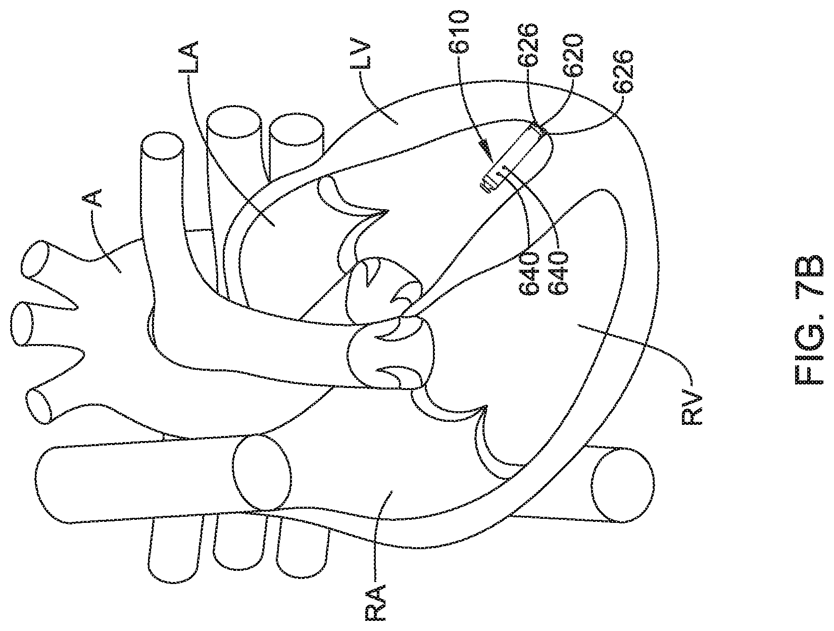
1. A leadless cardiac pacemaker (LCP) configured to sense cardiac activity and to pace a patient's heart, the LCP comprising: a housing having a proximal end and a distal end; a fixation member configured for fixing the housing to an inner wall of the patient's heart such that both the proximal end and the distal end of the housing are located inside of a chamber of the patient's heart, the fixation member comprising a plurality of hooks or tines extending distally from the distal end of the housing and into the patient's heart to anchor the distal end of the housing to the patient's heart; a first electrode secured relative to the housing and exposed to the environment outside of the housing; a second electrode secured relative to the housing and exposed to the environment outside of the housing; the housing having a diaphragm that is exposed to the environment outside of the housing, the diaphragm is positioned on the proximal end of the housing and is responsive to a pressure applied to the diaphragm by the environment outside the proximal end of the housing; a pressure sensor within the housing, the pressure sensor having a pressure sensor diaphragm that is responsive to a pressure applied to the pressure sensor diaphragm and provides a pressure sensor output signal that is representative of the pressure applied to the pressure sensor diaphragm; a fluid filled cavity in fluid communication with both the diaphragm of the housing and the pressure sensor diaphragm of the pressure sensor, the fluid filled cavity is configured to communicate a measure related to the pressure applied by the environment to the diaphragm of the housing to the pressure sensor diaphragm of the pressure sensor; and circuitry in the housing in operative communication with the pressure sensor, the circuitry configured to determine a pressure exterior to the housing based on the pressure sensor output signal, and further configured to provide a plurality of pacing pulses via the first and second electrodes, wherein a timing of at least some of the plurality of pacing pulses is based at least in part on the pressure sensor output signal.
2. The LCP of claim 1, wherein the circuitry is further operatively coupled to the first electrode and the second electrode, and is further configured to: use one or more cardiac signals sensed by the first electrode and the second electrode to determine when the patient's heart is in a first phase of a cardiac cycle; and determine a pressure exterior to the housing based at least in part on the pressure sensor output signal taken during the first phase of a cardiac cycle.
3. The LCP of claim 2, wherein the first phase of a cardiac cycle is systole.
4. The LCP of claim 2, wherein the first phase of a cardiac cycle is diastole.
5. The LCP of claim 1, wherein the circuitry is configured to detect heart sounds of the patient's heart based at least in part on the pressure sensor output signal.
6. The LCP of claim 1, wherein the diaphragm of the housing comprises a localized thinning of a housing wall on the proximal end of the housing.
7. The LCP of claim 1, wherein the diaphragm of the housing comprises a region comprising a compliant material.
8. The LCP of claim 1, wherein the diaphragm of the housing comprises one or more bellows.
9. The LCP of claim 1, wherein the housing includes an elongated body with a distal end surface facing distally and a proximal end surface facing proximally, wherein the diaphragm of the housing is situated on the proximal end surface of the housing.
10. The LCP of claim 1, wherein the housing has a plurality of diaphragms that are exposed to the environment outside of the proximal end of the housing, each of the plurality of diaphragms are responsive to the pressure applied to the corresponding diaphragm by the environment outside of the housing.
11. The LCP of claim 1, wherein the fluid filled cavity is filled with an incompressible fluid.
12. The LCP of claim 11, wherein the incompressible fluid is a dielectric fluid.
13. The LCP of claim 1, further comprising an anti-thrombogenic coating disposed over the diaphragm of the housing.
14. The LCP of claim 1, wherein the diaphragm of the housing has a first surface area and the pressure sensor diaphragm of the pressure sensor has a second surface area, wherein a ratio of the first surface area to the second surface area is at least 5 to 1.
15. A leadless cardiac pacemaker (LCP) configured to sense cardiac activity and to pace a patient's heart, the LCP comprising: a housing having an elongated body with a proximal end having a proximal end surface facing proximally and a distal end having a distal end surface facing distally; a first electrode secured relative to the housing and exposed to the environment outside of the housing; a second electrode secured relative to the housing and exposed to the environment outside of the housing; a fixation member at the distal end of the housing configured for fixing the distal end of the housing to an inner wall of a chamber of the patient's heart with the proximal end of the housing extending away from the inner wall and into the chamber of the patient's heart, the fixation member comprising a plurality of hooks or tines extending distally from the distal end of the housing and into the patient's heart to anchor the distal end of the housing to the patient's heart; the housing having a diaphragm that is exposed to the environment outside of the housing, the diaphragm is responsive to a pressure applied to the diaphragm by the environment outside of the housing, wherein the pressure is a pressure inside of the chamber of the heart; one or more sensors coupled to the diaphragm of the housing for detecting a stress in the diaphragm of the housing, wherein the stress in the diaphragm is representative of the pressure applied to the diaphragm by the environment outside of the housing; circuitry in the housing in operative communication with the one or more sensors for determining a pressure exterior to the housing based at least in part on the detected stress in the diaphragm of the housing; and wherein the diaphragm of the housing is situated on the proximal end surface of the housing.
16. The LCP of claim 15, wherein the diaphragm of the housing comprises a localized thinning of a housing wall of the housing.
17. The LCP of claim 16, wherein the localized thinning of the housing wall comprises a transition from a first thicker wall thickness to a second thinner wall thickness.
18. The LCP of claim 17, wherein the one or more sensors comprises a piezo resistor, and wherein the stress in the diaphragm comprises one or more of compression and stretching.
19. A leadless cardiac pacemaker (LCP) comprising: a housing having a proximal end and a distal end; a first electrode secured relative to the housing and exposed to the environment outside of the housing; a second electrode secured relative to the housing and exposed to the environment outside of the housing; the housing having a diaphragm that is exposed to the environment outside of the housing, the diaphragm is responsive to a pressure applied to the diaphragm by the environment outside of the housing; a pressure sensor within the housing, the pressure sensor having a pressure sensor diaphragm that is responsive to a pressure applied to the pressure sensor diaphragm and provides a pressure sensor output signal that is representative of the pressure applied to the pressure sensor diaphragm; a sealed fluid filled cavity extending between the diaphragm of the housing and the pressure sensor diaphragm, the sealed fluid filled cavity including a fluid that is in fluid communication with both the diaphragm of the housing and the pressure sensor diaphragm of the pressure sensor, the sealed fluid filled cavity is configured to communicate a measure related to the pressure applied by the environment to the diaphragm of the housing to the pressure sensor diaphragm of the pressure sensor; a component cavity in the housing defined by a component cavity inner wall, the component cavity fluidly isolated from the sealed fluid filled cavity; circuitry mounted in the component cavity in the housing with at least part of the circuitry spaced from the component cavity inner wall, the circuitry in operative communication with the pressure sensor, the circuitry configured to determine a pressure exterior to the housing based on the pressure sensor output signal, and further configured to communicate with another device via the first and second electrodes; a battery mounted in the component cavity in the housing for providing power to the circuitry; the battery and the circuitry both fluidly isolated from the fluid in the sealed fluid filled cavity; and the circuitry configured to provide a plurality of pacing pulses via the first and second electrodes, wherein a timing of at least some of the plurality of pacing pulses is based at least in part on the pressure sensor output signal.
Description
TECHNICAL FIELD
The present disclosure generally relates to implantable medical devices and more particularly to implantable medical devices with pressure sensors
BACKGROUND
Implantable medical devices are commonly used to perform a variety of functions, such as to monitor one or more conditions and/or delivery therapy to a patient. In some cases, an implantable medical device may deliver neurostimulation therapy to a patient. In some cases, an implantable medical device may simply monitor one or more conditions, such as pressure, acceleration, cardiac events, and may communicate the detected conditions or events to another device, such as another implantable medical device or an external programmer.
In some cases, an implantable medical device may be configured to deliver pacing and/or defibrillation therapy to a patient. Such implantable medical devices may treat patients suffering from various heart conditions that may result in a reduced ability of the heart to deliver sufficient amounts of blood to a patient's body. In some cases, heart conditions may lead to rapid, irregular, and/or inefficient heart contractions. To help alleviate some of these conditions, various devices (e.g., pacemakers, defibrillators, etc.) may be implanted into a patient's body. When so provided, such devices can monitor and provide therapy, such as electrical stimulation therapy, to the patient's heart to help the heart operate in a more normal, efficient and/or safe manner. In some cases, a patient may have multiple implanted devices that cooperate to monitor and/or provide therapy to the patient's heart.
SUMMARY
The present disclosure generally relates to implantable medical devices and more particularly to implantable medical devices with pressure sensors.
In a first example, a leadless cardiac pacemaker (LCP) may be configured to sense cardiac activity and to pace a patient's heart. The LCP may comprise a housing having a proximal end and a distal end, a first electrode secured relative to the housing and exposed to the environment outside of the housing, and a second electrode secured relative to the housing and exposed to the environment outside of the housing. The housing may have a diaphragm that is exposed to the environment outside of the housing. The diaphragm may be responsive to a pressure applied to the diaphragm by the environment outside of the housing. A pressure sensor may be within the housing may have a pressure sensor diaphragm that is responsive to a pressure applied to the pressure sensor diaphragm and provides a pressure sensor output signal that is representative of the pressure applied to the pressure sensor diaphragm. A fluid filled cavity may be in fluid communication with both the diaphragm of the housing and the pressure sensor diaphragm of the pressure sensor. The fluid filled cavity may be configured to communicate a measure related to the pressure applied by the environment to the diaphragm of the housing to the pressure sensor diaphragm of the pressure sensor. Circuitry in the housing may be in operative communication with the pressure sensor. The circuitry may be configured to determine a pressure exterior to the housing based on the pressure sensor output signal.
Alternatively or additionally to any of the examples above, in another example, the circuitry may be further operatively coupled to the first electrode and the second electrode, and may be further configured to use one or more cardiac signals sensed by the first electrode and the second electrode to determine when the patient's heart is in a first phase of a cardiac cycle and determine a pressure exterior to the housing based at least in part on the pressure sensor output signal taken during the first phase of a cardiac cycle. Alternatively or additionally to any of the examples above, in another example, the first phase of a cardiac cycle may be systole.
Alternatively or additionally to any of the examples above, in another example, the first phase of a cardiac cycle may be diastole.
Alternatively or additionally to any of the examples above, in another example, the circuitry may be configured to detect heart sounds of the patient's heart based at least in part on the pressure sensor output signal.
Alternatively or additionally to any of the examples above, in another example, the diaphragm of the housing may comprise a localized thinning of a housing wall of the housing.
Alternatively or additionally to any of the examples above, in another example, the diaphragm of the housing may comprise a region comprising a compliant material.
Alternatively or additionally to any of the examples above, in another example, the diaphragm of the housing may comprise one or more bellows.
Alternatively or additionally to any of the examples above, in another example, the LCP may further comprise a fixation member at the distal end of the housing for fixing the distal end of the housing to the patient's heart, and wherein the diaphragm of the housing may be adjacent the proximal end of the housing.
Alternatively or additionally to any of the examples above, in another example, the housing may include an elongated body with a distal end surface facing distally and a proximal end surface facing proximally, wherein the diaphragm of the housing may be situated on the proximal end surface of the housing.
Alternatively or additionally to any of the examples above, in another example, the housing may have a plurality of diaphragms that are exposed to the environment outside of the housing, each of the plurality of diaphragms are responsive to the pressure applied to the corresponding diaphragm by the environment outside of the housing.
Alternatively or additionally to any of the examples above, in another example, the fluid filled cavity may be filled with an incompressible fluid.
Alternatively or additionally to any of the examples above, in another example, the incompressible fluid may be a dielectric fluid.
Alternatively or additionally to any of the examples above, in another example, the LCP may further comprise an anti-thrombogenic coating disposed over the diaphragm of the housing.
Alternatively or additionally to any of the examples above, in another example, the diaphragm of the housing may have a first surface area and the pressure sensor diaphragm of the pressure sensor may have a second surface area, wherein a ratio of the first surface area to the second surface area is at least 5 to 1.
In another example, a leadless cardiac pacemaker (LCP) may be configured to sense cardiac activity and to pace a patient's heart. The LCP may comprise a housing having a proximal end and a distal end, a first electrode secured relative to the housing and exposed to the environment outside of the housing, and a second electrode secured relative to the housing and exposed to the environment outside of the housing. The housing may have a diaphragm that is exposed to the environment outside of the housing. The diaphragm may be responsive to a pressure applied to the diaphragm by the environment outside of the housing. One or more sensors may be coupled to the diaphragm of the housing for detecting a stress in the diaphragm of the housing, wherein the stress in the diaphragm is representative of the pressure applied to the diaphragm by the environment outside of the housing. Circuitry in the housing may be in operative communication with the one or more sensors for determining a pressure exterior to the housing based at least in part on the detected stress in the diaphragm of the housing.
Alternatively or additionally to any of the examples above, in another example, the diaphragm of the housing may comprise a localized thinning of a housing wall of the housing.
Alternatively or additionally to any of the examples above, in another example, the localized thinning of the housing wall may comprise a transition from a first thicker wall thickness to a second thinner wall thickness.
Alternatively or additionally to any of the examples above, in another example, the one or more sensors may comprise a piezo resistor, and wherein the stress in the diaphragm comprises one or more of compression and stretching.
In another example, an implantable medical device (IMD) may comprise a housing having a proximal end and a distal end, a first electrode secured relative to the housing and exposed to the environment outside of the housing, and a second electrode secured relative to the housing and exposed to the environment outside of the housing. The housing may have a diaphragm that is exposed to the environment outside of the housing. The diaphragm may be responsive to a pressure applied to the diaphragm by the environment outside of the housing. A pressure sensor may be positioned within the housing and may have a pressure sensor diaphragm that is responsive to a pressure applied to the pressure sensor diaphragm and provides a pressure sensor output signal that is representative of the pressure applied to the pressure sensor diaphragm. A fluid filled cavity may be in fluid communication with both the diaphragm of the housing and the pressure sensor diaphragm of the pressure sensor. The fluid filled cavity may be configured to communicate a measure related to the pressure applied by the environment to the diaphragm of the housing to the pressure sensor diaphragm of the pressure sensor. Circuitry in the housing may be in operative communication with the pressure sensor. The circuitry may be configured to determine a pressure exterior to the housing based on the pressure sensor output signal, and further configured to communicate with another device via the first and second electrodes.
The above summary is not intended to describe each embodiment or every implementation of the present disclosure. Advantages and attainments, together with a more complete understanding of the disclosure, will become apparent and appreciated by referring to the following description and claims taken in conjunction with the accompanying drawings.
BRIEF DESCRIPTION OF THE DRAWINGS
The disclosure may be more completely understood in consideration of the following description of various illustrative embodiments in connection with the accompanying drawings, in which:
FIG. 1 is a schematic block diagram of an illustrative leadless cardiac pacemaker (LCP) according to one example of the present disclosure;
FIG. 2 is a schematic block diagram of another medical device (MD), which may be used in conjunction with an LCP 100 (FIG. 1) in order to detect and/or treat cardiac arrhythmias and other heart conditions;
FIG. 3 is a schematic diagram of an exemplary medical system that includes multiple LCPs and/or other devices in communication with one another;
FIG. 4 is a schematic diagram of an exemplary medical system that includes an LCP and another medical device, in accordance with yet another example of the present disclosure;
FIG. 5 is a schematic diagram of an exemplary medical system that includes an LCP and another medical device, in accordance with yet another example of the present disclosure;
FIG. 6 is a side view of an illustrative implantable leadless cardiac pacing device;
FIG. 7A is a plan view of an example leadless cardiac pacing device implanted within a heart during ventricular filling;
FIG. 7B is a plan view of an example leadless cardiac pacing device implanted within a heart during ventricular contraction;
FIG. 8 is a graph showing example pressures and volumes within the heart over time;
FIG. 9 is a schematic cross-sectional view of a an illustrative leadless cardiac pacing device;
FIG. 10 is a schematic cross-sectional view of the proximal end of the illustrative leadless cardiac pacing device of FIG. 9;
FIG. 11 is a schematic cross-sectional view of an illustrative pressure sensor for use with a leadless cardiac pacing device;
FIG. 12 is a schematic cross-sectional view of a proximal end portion of another illustrative leadless cardiac pacing device;
FIG. 13 is a schematic cross-sectional view of a proximal end portion of another illustrative leadless cardiac pacing device;
FIG. 14 is a schematic cross-sectional view of a proximal end portion of another illustrative leadless cardiac pacing device;
FIG. 15 is an end view of the proximal end of another illustrative leadless cardiac pacing device;
FIG. 16 is a schematic perspective view of another illustrative leadless cardiac pacing device;
FIG. 17A is a schematic partial cross-sectional view of another illustrative leadless cardiac pacing device;
FIG. 17B is a cross sectional view of the illustrative leadless cardiac pacing device of FIG. 17A, taken along line 17B-17B; and
FIG. 18 is a schematic perspective view of another illustrative leadless cardiac pacing device.
While the disclosure is amenable to various modifications and alternative forms, specifics thereof have been shown by way of example in the drawings and will be described in detail. It should be understood, however, that the intention is not to limit aspects of the disclosure to the particular illustrative embodiments described. On the contrary, the intention is to cover all modifications, equivalents, and alternatives falling within the spirit and scope of the disclosure.
DESCRIPTION
The following description should be read with reference to the drawings in which similar elements in different drawings are numbered the same. The description and the drawings, which are not necessarily to scale, depict illustrative embodiments and are not intended to limit the scope of the disclosure. While the present disclosure is applicable to any suitable implantable medical device (IMD), the description below uses pacemakers and more particularly leadless cardiac pacemakers (LCP) as particular examples.
A normal, healthy heart induces contraction by conducting intrinsically generated electrical signals throughout the heart. These intrinsic signals cause the muscle cells or tissue of the heart to contract. This contraction forces blood out of and into the heart, providing circulation of the blood throughout the rest of the body. However, many patients suffer from cardiac conditions that affect this contractility of their hearts. For example, some hearts may develop diseased tissues that no longer generate or conduct intrinsic electrical signals. In some examples, diseased cardiac tissues conduct electrical signals at differing rates, thereby causing an unsynchronized and inefficient contraction of the heart. In other examples, a heart may initiate intrinsic signals at such a low rate that the heart rate becomes dangerously low. In still other examples, a heart may generate electrical signals at an unusually high rate. In some cases such an abnormality can develop into a fibrillation state, where the contraction of the patient's heart chambers are almost completely de-synchronized and the heart pumps very little to no blood. Implantable medical devices, which may be configured to determine occurrences of such cardiac abnormalities or arrhythmias and deliver one or more types of electrical stimulation therapy to patient's hearts, may help to terminate or alleviate these and other cardiac conditions.
FIG. 1 depicts an illustrative leadless cardiac pacemaker (LCP) that may be implanted into a patient and may operate to prevent, control, or terminate cardiac arrhythmias in patients by, for example, appropriately employing one or more therapies (e.g. anti-tachycardia pacing (ATP) therapy, cardiac resynchronization therapy (CRT), bradycardia therapy, defibrillation pulses, or the like). As can be seen in FIG. 1, the LCP 100 may be a compact device with all components housed within the LCP 100 or directly on the housing 120. In the example shown in FIG. 1, the LCP 100 may include a communication module 102, a pulse generator module 104, an electrical sensing module 106, a mechanical sensing module 108, a processing module 110, a battery 112, and electrodes 114. The LCP 100 may include more or less modules, depending on the application.
The communication module 102 may be configured to communicate with devices such as sensors, other medical devices, and/or the like, that are located externally to the LCP 100. Such devices may be located either external or internal to the patient's body. Irrespective of the location, remote devices (i.e. external to the LCP 100 but not necessarily external to the patient's body) can communicate with the LCP 100 via the communication module 102 to accomplish one or more desired functions. For example, the LCP 100 may communicate information, such as sensed electrical signals, data, instructions, messages, etc., to an external medical device through the communication module 102. The external medical device may use the communicated signals, data, instructions and/or messages to perform various functions, such as determining occurrences of arrhythmias, delivering electrical stimulation therapy, storing received data, analyzing received data, and/or performing any other suitable function. The LCP 100 may additionally receive information such as signals, data, instructions and/or messages from the external medical device through the communication module 102, and the LCP 100 may use the received signals, data, instructions and/or messages to perform various functions, such as determining occurrences of arrhythmias, delivering electrical stimulation therapy, storing received data, analyzing received data, and/or performing any other suitable function. The communication module 102 may be configured to use one or more methods for communicating with remote devices. For example, the communication module 102 may communicate via radiofrequency (RF) signals, inductive coupling, optical signals, acoustic signals, conducted communication signals, and/or any other signals suitable for communication.
In the example shown in FIG. 1, the pulse generator module 104 may be electrically connected to the electrodes 114. In some examples, the LCP 100 may include one or more additional electrodes 114'. In such examples, the pulse generator 104 may also be electrically connected to the additional electrodes 114'. The pulse generator module 104 may be configured to generate electrical stimulation signals. For example, the pulse generator module 104 may generate electrical stimulation signals by using energy stored in a battery 112 within the LCP 100 and deliver the generated electrical stimulation signals via the electrodes 114 and/or 114'. Alternatively, or additionally, the pulse generator 104 may include one or more capacitors, and the pulse generator 104 may charge the one or more capacitors by drawing energy from the battery 112. The pulse generator 104 may then use the energy of the one or more capacitors to deliver the generated electrical stimulation signals via the electrodes 114 and/or 114'. In at least some examples, the pulse generator 104 of the LCP 100 may include switching circuitry to selectively connect one or more of the electrodes 114 and/or 114' to the pulse generator 104 in order to select which of the electrodes 114/114' (and/or other electrodes) the pulse generator 104 delivers the electrical stimulation therapy. The pulse generator module 104 may generate electrical stimulation signals with particular features or in particular sequences in order to provide one or multiple of a number of different stimulation therapies. For example, the pulse generator module 104 may be configured to generate electrical stimulation signals to provide electrical stimulation therapy to combat bradycardia, tachycardia, cardiac dyssynchrony, bradycardia arrhythmias, tachycardia arrhythmias, fibrillation arrhythmias, cardiac synchronization arrhythmias and/or to produce any other suitable electrical stimulation therapy. Some more common electrical stimulation therapies include bradycardia therapy, anti-tachycardia pacing (ATP) therapy, cardiac resynchronization therapy (CRT), and cardioversion/defibrillation therapy.
In some examples, the LCP 100 may not include a pulse generator 104 or may turn off the pulse generator 104. When so provided, the LCP 100 may be a diagnostic only device. In such examples, the LCP 100 may not deliver electrical stimulation therapy to a patient. Rather, the LCP 100 may collect data about cardiac electrical activity and/or physiological parameters of the patient and communicate such data and/or determinations to one or more other medical devices via the communication module 102.
In some examples, the LCP 100 may include an electrical sensing module 106, and in some cases, a mechanical sensing module 108. The electrical sensing module 106 may be configured to sense the cardiac electrical activity of the heart. For example, the electrical sensing module 106 may be connected to the electrodes 114/114', and the electrical sensing module 106 may be configured to receive cardiac electrical signals conducted through the electrodes 114/114'. The cardiac electrical signals may represent local information from the chamber in which the LCP 100 is implanted. For instance, if the LCP 100 is implanted within a ventricle of the heart, cardiac electrical signals sensed by the LCP 100 through the electrodes 114/114' may represent ventricular cardiac electrical signals. The mechanical sensing module 108 may include one or more sensors, such as an accelerometer, a blood pressure sensor, a heart sound sensor, a blood-oxygen sensor, a temperature sensor, a flow sensor and/or any other suitable sensors that are configured to measure one or more mechanical and/or chemical parameters of the patient. Both the electrical sensing module 106 and the mechanical sensing module 108 may be connected to a processing module 110, which may provide signals representative of the sensed mechanical parameters. Although described with respect to FIG. 1 as separate sensing modules, in some cases, the electrical sensing module 106 and the mechanical sensing module 108 may be combined into a single sensing module, as desired.
The electrodes 114/114' can be secured relative to the housing 120 but exposed to the tissue and/or blood surrounding the LCP 100. In some cases, the electrodes 114 may be generally disposed on either end of the LCP 100 and may be in electrical communication with one or more of the modules 102, 104, 106, 108, and 110. The electrodes 114/114' may be supported by the housing 120, although in some examples, the electrodes 114/114' may be connected to the housing 120 through short connecting wires such that the electrodes 114/114' are not directly secured relative to the housing 120. In examples where the LCP 100 includes one or more electrodes 114', the electrodes 114' may in some cases be disposed on the sides of the LCP 100, which may increase the number of electrodes by which the LCP 100 may sense cardiac electrical activity, deliver electrical stimulation and/or communicate with an external medical device. The electrodes 114/114' can be made up of one or more biocompatible conductive materials such as various metals or alloys that are known to be safe for implantation within a human body. In some instances, the electrodes 114/114' connected to LCP 100 may have an insulative portion that electrically isolates the electrodes 114/114' from adjacent electrodes, the housing 120, and/or other parts of the LCP 100.
The processing module 110 can be configured to control the operation of the LCP 100. For example, the processing module 110 may be configured to receive electrical signals from the electrical sensing module 106 and/or the mechanical sensing module 108. Based on the received signals, the processing module 110 may determine, for example, occurrences and, in some cases, types of arrhythmias. Based on any determined arrhythmias, the processing module 110 may control the pulse generator module 104 to generate electrical stimulation in accordance with one or more therapies to treat the determined arrhythmia(s). The processing module 110 may further receive information from the communication module 102. In some examples, the processing module 110 may use such received information to help determine whether an arrhythmia is occurring, determine a type of arrhythmia, and/or to take particular action in response to the information. The processing module 110 may additionally control the communication module 102 to send/receive information to/from other devices.
In some examples, the processing module 110 may include a pre-programmed chip, such as a very-large-scale integration (VLSI) chip and/or an application specific integrated circuit (ASIC). In such embodiments, the chip may be pre-programmed with control logic in order to control the operation of the LCP 100. By using a pre-programmed chip, the processing module 110 may use less power than other programmable circuits (e.g. general purpose programmable microprocessors) while still being able to maintain basic functionality, thereby potentially increasing the battery life of the LCP 100. In other examples, the processing module 110 may include a programmable microprocessor. Such a programmable microprocessor may allow a user to modify the control logic of the LCP 100 even after implantation, thereby allowing for greater flexibility of the LCP 100 than when using a pre-programmed ASIC. In some examples, the processing module 110 may further include a memory, and the processing module 110 may store information on and read information from the memory. In other examples, the LCP 100 may include a separate memory (not shown) that is in communication with the processing module 110, such that the processing module 110 may read and write information to and from the separate memory.
The battery 112 may provide power to the LCP 100 for its operations. In some examples, the battery 112 may be a non-rechargeable lithium-based battery. In other examples, a non-rechargeable battery may be made from other suitable materials, as desired. Because the LCP 100 is an implantable device, access to the LCP 100 may be limited after implantation. Accordingly, it is desirable to have sufficient battery capacity to deliver therapy over a period of treatment such as days, weeks, months, years or even decades. In some instances, the battery 112 may a rechargeable battery, which may help increase the useable lifespan of the LCP 100. In still other examples, the battery 112 may be some other type of power source, as desired.
To implant the LCP 100 inside a patient's body, an operator (e.g., a physician, clinician, etc.), may fix the LCP 100 to the cardiac tissue of the patient's heart. To facilitate fixation, the LCP 100 may include one or more anchors 116. The anchor 116 may include any one of a number of fixation or anchoring mechanisms. For example, the anchor 116 may include one or more pins, staples, threads, screws, helix, tines, and/or the like. In some examples, although not shown, the anchor 116 may include threads on its external surface that may run along at least a partial length of the anchor 116. The threads may provide friction between the cardiac tissue and the anchor to help fix the anchor 116 within the cardiac tissue. In other examples, the anchor 116 may include other structures such as barbs, spikes, or the like to facilitate engagement with the surrounding cardiac tissue.
FIG. 2 depicts an example of another medical device (MD) 200, which may be used in conjunction with an LCP 100 (FIG. 1) in order to detect and/or treat cardiac arrhythmias and other heart conditions. In the example shown, the MD 200 may include a communication module 202, a pulse generator module 204, an electrical sensing module 206, a mechanical sensing module 208, a processing module 210, and a battery 218. Each of these modules may be similar to the modules 102, 104, 106, 108, and 110 of the LCP 100. Additionally, the battery 218 may be similar to the battery 112 of the LCP 100. In some examples, the MD 200 may have a larger volume within the housing 220 than LCP 100. In such examples, the MD 200 may include a larger battery and/or a larger processing module 210 capable of handling more complex operations than the processing module 110 of the LCP 100.
While it is contemplated that the MD 200 may be another leadless device such as shown in FIG. 1, in some instances the MD 200 may include leads such as leads 212. The leads 212 may include electrical wires that conduct electrical signals between the electrodes 214 and one or more modules located within the housing 220. In some cases, the leads 212 may be connected to and extend away from the housing 220 of the MD 200. In some examples, the leads 212 are implanted on, within, or adjacent to a heart of a patient. The leads 212 may contain one or more electrodes 214 positioned at various locations on the leads 212, and in some cases at various distances from the housing 220. Some of the leads 212 may only include a single electrode 214, while other leads 212 may include multiple electrodes 214. Generally, the electrodes 214 are positioned on the leads 212 such that when the leads 212 are implanted within the patient, one or more of the electrodes 214 are positioned to perform a desired function. In some cases, the one or more of the electrodes 214 may be in contact with the patient's cardiac tissue. In some cases, the one or more of the electrodes 214 may be positioned substernally or subcutaneously but adjacent the patient's heart. In some cases, the electrodes 214 may conduct intrinsically generated electrical signals to the leads 212, e.g. signals representative of intrinsic cardiac electrical activity. The leads 212 may, in turn, conduct the received electrical signals to one or more of the modules 202, 204, 206, and 208 of the MD 200. In some cases, the MD 200 may generate electrical stimulation signals, and the leads 212 may conduct the generated electrical stimulation signals to the electrodes 214. The electrodes 214 may then conduct the electrical signals and delivery the signals to the patient's heart (either directly or indirectly).
The mechanical sensing module 208, as with the mechanical sensing module 108, may contain or be electrically connected to one or more sensors, such as accelerometers, blood pressure sensors, heart sound sensors, blood-oxygen sensors, acoustic sensors, ultrasonic sensors and/or other sensors which are configured to measure one or more mechanical/chemical parameters of the heart and/or patient. In some examples, one or more of the sensors may be located on the leads 212, but this is not required. In some examples, one or more of the sensors may be located in the housing 220.
While not required, in some examples, the MD 200 may be an implantable medical device. In such examples, the housing 220 of the MD 200 may be implanted in, for example, a transthoracic region of the patient. The housing 220 may generally include any of a number of known materials that are safe for implantation in a human body and may, when implanted, hermetically seal the various components of the MD 200 from fluids and tissues of the patient's body.
In some cases, the MD 200 may be an implantable cardiac pacemaker (ICP). In this example, the MD 200 may have one or more leads, for example leads 212, which are implanted on or within the patient's heart. The one or more leads 212 may include one or more electrodes 214 that are in contact with cardiac tissue and/or blood of the patient's heart. The MD 200 may be configured to sense intrinsically generated cardiac electrical signals and determine, for example, one or more cardiac arrhythmias based on analysis of the sensed signals. The MD 200 may be configured to deliver CRT, ATP therapy, bradycardia therapy, and/or other therapy types via the leads 212 implanted within the heart or in concert with the LCP by commanding the LCP to pace. In some examples, the MD 200 may additionally be configured provide defibrillation therapy.
In some instances, the MD 200 may be an implantable cardioverter-defibrillator (ICD). In such examples, the MD 200 may include one or more leads implanted within a patient's heart. The MD 200 may also be configured to sense cardiac electrical signals, determine occurrences of tachyarrhythmias based on the sensed signals, and may be configured to deliver defibrillation therapy in response to determining an occurrence of a tachyarrhythmia. In some instances, the MD 200 may be a subcutaneous implantable cardioverter-defibrillator (S-ICD). In examples where the MD 200 is an S-ICD, one of the leads 212 may be a subcutaneously implanted lead. In at least some examples where the MD 200 is an S-ICD, the MD 200 may include only a single lead which is implanted subcutaneously, but this is not required. In some cases, the S-ICD lead may extend subcutaneously from the S-ICD can, around the sternum and may terminate adjacent the interior surface of the sternum.
In some examples, the MD 200 may not be an implantable medical device. Rather, the MD 200 may be a device external to the patient's body, and may include skin-electrodes that are placed on a patient's body. In such examples, the MD 200 may be able to sense surface electrical signals (e.g. cardiac electrical signals that are generated by the heart or electrical signals generated by a device implanted within a patient's body and conducted through the body to the skin). In such examples, the MD 200 may be configured to deliver various types of electrical stimulation therapy, including, for example, defibrillation therapy. The MD 200 may be further configured to deliver electrical stimulation via the LCP by commanding the LCP to deliver the therapy.
FIG. 3 shows an example medical device system with a communication pathway through which multiple medical devices 302, 304, 306, and/or 310 may communicate. In the example shown, the medical device system 300 may include LCPs 302 and 304, an external medical device 306, and other sensors/devices 310. The external device 306 may be any of the devices described previously with respect to MD 200. In some embodiments, the external device 306 may be provided with or be in communication with a display 312. The display 312 may be a personal computer, tablet computer, smart phone, laptop computer, or other display as desired. In some instances, the display 312 may include input means for receiving an input from a user. For example, the display 312 may also include a keyboard, mouse, actuatable (e.g. pushable) buttons, or a touchscreen display. These are just examples. The other sensors/devices 310 may be any of the devices described previously with respect to the MD 200. In some instances, the other sensors/devices 310 may include a sensor, such as an accelerometer or blood pressure sensor, or the like. In some cases, the other sensors/devices 310 may include an external programmer device that may be used to program one or more devices of the system 300.
Various devices of the system 300 may communicate via a communication pathway 308. For example, the LCPs 302 and/or 304 may sense intrinsic cardiac electrical signals and may communicate such signals to one or more other devices 302/304, 306, and 310 of the system 300 via the communication pathway 308. In one example, one or more of the devices 302/304 may receive such signals and, based on the received signals, determine an occurrence of an arrhythmia. In some cases, the device or devices 302/304 may communicate such determinations to one or more other devices 306 and 310 of the system 300. In some cases, one or more of the devices 302/304, 306, and 310 of the system 300 may take action based on the communicated determination of an arrhythmia, such as by delivering a suitable electrical stimulation to the heart of the patient. In another example, the LCPs 302 and/or 304 may sense indications of blood pressure (e.g. via one or more pressure sensors) and indications of volume (e.g. via an impedance between the electrodes of an LCP or between LCPs via an ultrasound transducer placed within the LCP, or via strain sensors placed on the heart in communication with the LCP). In one example, one or more of the devices 302/304 may receive such signals and, based on the received signals, determine a pressure-volume loop, and in some cases may communicate such information to one or more other devices 302/304, 306, and 310 of the system 300 via the communication pathway 308.
It is contemplated that the communication pathway 308 may communicate using RF signals, inductive coupling, conductive coupling optical signals, acoustic signals, or any other signals suitable for communication. Additionally, in at least some examples, the device communication pathway 308 may comprise multiple signal types. For instance, the other sensors/device 310 may communicate with the external device 306 using a first signal type (e.g. RF communication) but communicate with the LCPs 302/304 using a second signal type (e.g. conducted communication, inductive communication). Further, in some examples, communication between devices may be limited. For instance, as described above, in some examples, the LCPs 302/304 may communicate with the external device 306 only through the other sensors/devices 310, where the LCPs 302/304 send signals to the other sensors/devices 310, and the other sensors/devices 310 relay the received signals to the external device 306.
In some cases, the communication pathway 308 may include conducted communication. Accordingly, devices of the system 300 may have components that allow for such conducted communication. For instance, the devices of the system 300 may be configured to transmit conducted communication signals (e.g. current and/or voltage pulses) into the patient's body via one or more electrodes of a transmitting device, and may receive the conducted communication signals (e.g. pulses) via one or more electrodes of a receiving device. The patient's body may "conduct" the conducted communication signals (e.g. pulses) from the one or more electrodes of the transmitting device to the electrodes of the receiving device in the system 300. In such examples, the delivered conducted communication signals (e.g. pulses) may differ from pacing or other therapy signals. For example, the devices of the system 300 may deliver electrical communication pulses at an amplitude/pulse width that is sub-threshold to the heart. Although, in some cases, the amplitude/pulse width of the delivered electrical communication pulses may be above the capture threshold of the heart, but may be delivered during a refractory period of the heart and/or may be incorporated in or modulated onto a pacing pulse, if desired.
Delivered electrical communication pulses may be modulated in any suitable manner to encode communicated information. In some cases, the communication pulses may be pulse width modulated or amplitude modulated. Alternatively, or in addition, the time between pulses may be modulated to encode desired information. In some cases, conducted communication pulses may be voltage pulses, current pulses, biphasic voltage pulses, biphasic current pulses, or any other suitable electrical pulse as desired.
In some cases, the communication pathway 308 may include inductive communication, and when so provided, the devices of the system 300 may be configured to transmit/receive inductive communication signals.
FIGS. 4 and 5 show illustrative medical device systems that may be configured to operate according to techniques disclosed herein. In FIG. 4, an LCP 402 is shown fixed to the interior of the left ventricle of the heart 410, and a pulse generator 406 is shown coupled to a lead 412 having one or more electrodes 408a, 408b, 408c. In some cases, the pulse generator 406 may be part of a subcutaneous implantable cardioverter-defibrillator (S-ICD), and the one or more electrodes 408a, 408b, 408c may be positioned subcutaneously adjacent the heart. In some cases, the S-ICD lead may extend subcutaneously from the S-ICD can, around the sternum and one or more electrodes 408a, 408b, 408c may be positioned adjacent the interior surface of the sternum. In some cases, the LCP 402 may communicate with the subcutaneous implantable cardioverter-defibrillator (S-ICD).
In some cases, the LCP 402 may be in the right ventricle, right atrium or left atrium of the heart, as desired. In some cases, more than one LCP 402 may be implanted. For example, one LCP may be implanted in the right ventricle and another may be implanted in the right atrium. In another example, one LCP may be implanted in the right ventricle and another may be implanted in the left ventricle. In yet another example, one LCP may be implanted in each of the chambers of the heart.
In FIG. 5, an LCP 502 is shown fixed to the interior of the left ventricle of the heart 510, and a pulse generator 506 is shown coupled to a lead 512 having one or more electrodes 504a, 504b, 504c. In some cases, the pulse generator 506 may be part of an implantable cardiac pacemaker (ICP) and/or an implantable cardioverter-defibrillator (ICD), and the one or more electrodes 504a, 504b, 504c may be positioned in the heart 510. In some cases, the LCP 502 may communicate with the implantable cardiac pacemaker (ICP) and/or an implantable cardioverter-defibrillator (ICD).
The medical device systems 400 and 500 may also include an external support device, such as external support devices 420 and 520. The external support devices 420 and 520 can be used to perform functions such as device identification, device programming and/or transfer of real-time and/or stored data between devices using one or more of the communication techniques described herein. As one example, communication between the external support device 420 and the pulse generator 406 is performed via a wireless mode, and communication between the pulse generator 406 and the LCP 402 is performed via a conducted mode. In some examples, communication between the LCP 402 and the external support device 420 is accomplished by sending communication information through the pulse generator 406. However, in other examples, communication between the LCP 402 and the external support device 420 may be via a communication module. In some embodiments, the external support devices 420, 520 may be provided with or be in communication with a display 422, 522. The display 422, 522 may be a personal computer, tablet computer, smart phone, laptop computer, or other display as desired. In some instances, the display 422, 522 may include input means for receiving an input from a user. For example, the display 422, 522 may also include a keyboard, mouse, actuatable buttons, or be a touchscreen display. These are just examples.
FIGS. 4-5 illustrate two examples of medical device systems that may be configured to operate according to techniques disclosed herein. Other example medical device systems may include additional or different medical devices and/or configurations. For instance, other medical device systems that are suitable to operate according to techniques disclosed herein may include additional LCPs implanted within the heart. Another example medical device system may include a plurality of LCPs without other devices such as the pulse generator 406 or 506, with at least one LCP capable of delivering defibrillation therapy. In yet other examples, the configuration or placement of the medical devices, leads, and/or electrodes may be different from those depicted in FIGS. 4 and 5. Accordingly, it should be recognized that numerous other medical device systems, different from those depicted in FIGS. 4 and 5, may be operated in accordance with techniques disclosed herein. As such, the examples shown in FIGS. 4 and 5 should not be viewed as limiting in any way.
FIG. 6 is a side view of an illustrative implantable leadless cardiac pacemaker (LCP) 610. The LCP 610 may be similar in form and function to the LCP 100 described above. The LCP 610 may include any of the modules and/or structural features described herein. The LCP 610 may include a shell or housing 612 having a proximal end 614 and a distal end 616. The illustrative LCP 610 includes a first electrode 620 secured relative to the housing 612 and positioned adjacent to the distal end 616 of the housing 612 and a second electrode 622 secured relative to the housing 612 and positioned adjacent to the proximal end 614 of the housing 612. In some cases, the housing 612 may include a conductive material and may be insulated along a portion of its length. A section along the proximal end 614 may be free of insulation so as to define the second electrode 622. The electrodes 620, 622 may be sensing and/or pacing electrodes to provide electro-therapy and/or sensing capabilities. The first electrode 620 may be capable of being positioned against or may otherwise contact the cardiac tissue of the heart while the second electrode 622 may be spaced away from the first electrode 620. The first and/or second electrodes 620, 622 may be exposed to the environment outside the housing 612 (e.g. to blood and/or tissue).
It is contemplated that the housing 612 may take a variety of different shapes. For example, in some cases, the housing 612 may have a generally cylindrical shape. In other cases, the housing 612 may have a half-dome shape. In yet other embodiments, the housing 612 may be a rectangular prism. It is contemplated that the housing may take any cross sectional shape desired, including but not limited to annular, polygonal, oblong, square, etc.
In some cases, the LCP 610 may include a pulse generator (e.g., electrical circuitry) and a power source (e.g., a battery) within the housing 612 to provide electrical signals to the electrodes 620, 622 to control the pacing/sensing electrodes 620, 622. While not explicitly shown, the LCP 610 may also include a communications module, an electrical sensing module, a mechanical sensing module, and/or a processing module, and the associated circuitry, similar in form and function to the modules 102, 106, 108, 110 described above. The various modules and electrical circuitry may be disposed within the housing 612. Electrical communication between the pulse generator and the electrodes 620, 622 may provide electrical stimulation to heart tissue and/or sense a physiological condition.
In the example shown, the LCP 610 includes a fixation mechanism 624 proximate the distal end 616 of the housing 612. The fixation mechanism 624 is configured to attach the LCP 610 to a wall of the heart H, or otherwise anchor the LCP 610 to the anatomy of the patient. As shown in FIG. 6, in some instances, the fixation mechanism 624 may include one or more, or a plurality of hooks or tines 626 anchored into the cardiac tissue of the heart H to attach the LCP 610 to a tissue wall. In other instances, the fixation mechanism 624 may include one or more, or a plurality of passive tines, configured to entangle with trabeculae within the chamber of the heart H and/or a helical fixation anchor configured to be screwed into a tissue wall to anchor the LCP 610 to the heart H. These are just examples.
The LCP 610 may further include a docking member 630 proximate the proximal end 614 of the housing 612. The docking member 630 may be configured to facilitate delivery and/or retrieval of the LCP 610. For example, the docking member 630 may extend from the proximal end 614 of the housing 612 along a longitudinal axis of the housing 612. The docking member 630 may include a head portion 632 and a neck portion 634 extending between the housing 612 and the head portion 632. The head portion 632 may be an enlarged portion relative to the neck portion 634. For example, the head portion 632 may have a radial dimension from the longitudinal axis of the LCP 610 that is greater than a radial dimension of the neck portion 634 from the longitudinal axis of the LCP 610. In some cases, the docking member 630 may further include a tether retention structure (not explicitly shown) extending from or recessed within the head portion 632. The tether retention structure may define an opening configured to receive a tether or other anchoring mechanism therethrough. The retention structure may take any shape that provides an enclosed perimeter surrounding the opening such that a tether may be securably and releasably passed (e.g. looped) through the opening. In some cases, the retention structure may extend though the head portion 632, along the neck portion 634, and to or into the proximal end 614 of the housing 612. The docking member 630 may be configured to facilitate delivery of the LCP 610 to the intracardiac site and/or retrieval of the LCP 610 from the intracardiac site. While this describes one example docking member 630, it is contemplated that the docking member 630, when provided, can have any suitable configuration.
It is contemplated that the LCP 610 may include one or more pressure sensors 640 coupled to or formed within the housing 612 such that the pressure sensor(s) is exposed to and/or otherwise operationally coupled with the environment outside the housing 612 to measure blood pressures within the heart. In some cases, the one or more pressure sensors 640 may be coupled to an exterior surface of the housing 612. In other cases, the one or more pressures sensors 640 may be positioned within the housing 612 with a pressure acting on the housing and/or a port on the housing 612 to affect the pressure sensor 640. For example, if the LCP 610 is placed in the left ventricle, the pressure sensor(s) 640 may measure the pressure within the left ventricle. If the LCP 610 is placed in another portion of the heart (such as one of the atriums or the right ventricle), the pressures sensor(s) may measure the pressure within that portion of the heart. Some illustrative pressure sensor configurations will be described in more detail herein.
The pressure sensor(s) 640 may include a MEMS device, such as a MEMS device with a pressure diaphragm and piezoresistors on the diaphragm, a piezoelectric sensor, a capacitor-Micro-machined Ultrasonic Transducer (cMUT), a condenser, a micromanometer, a surface acoustic wave (SAW) device, or any other suitable sensor adapted for measuring cardiac pressure. The pressures sensor(s) 640 may be part of a mechanical sensing module described herein. It is contemplated that the pressure measurements obtained from the pressures sensor(s) 640 may be used to generate a pressure curve over cardiac cycles. The pressure sensor(s) 640 may measure/sense pressure in the chamber in which the LCP 610 is implanted. For example, an LCP 610 implanted in the left ventricle (LV) could sense LV pressure. The pressure sensor(s) 640 may be configured (either alone or in combination with other circuitry in the LCP 610) to derive change in pressure over time and used to adjust atrium to ventricle pacing delay to optimize cardiac resynchronization therapy (CRT). In some cases, the pressure sensor(s) 640 may be configured to detect a-waves and change the pacing timing of the LCP 610 for CRT optimization. It is further contemplated that sensing pressure could be used during the implant procedure to optimize the placement of the LCP 610 in the chamber (e.g., LV by sampling at different implant locations and using the best location. Frequent pressure monitoring may be beneficial for management of heart failure patients. Frequent pressure monitoring may also be useful for patients with chronic heart disease, hypertension, regurgitation, valve issues, atrial contraction detection, and to aid in addressing other problems. It is further contemplated that the pressure sensor(s) 640 may be used for monitoring respiration and associated diseases (e.g., chronic obstructive pulmonary disease (COPD), etc.). These are just examples.
In some cases, pressure readings may be taken in combination with a cardiac chamber volume measurement such an impedance measurement (e.g. the impedance between electrodes 620 and 622) to generate a pressure-impedance loop for one or more cardiac cycles. The impedance may be a surrogate for chamber volume, and thus the pressure-impedance loop may be representative of a pressure-volume loop for the heart H.
FIG. 7A is a plan view of the example leadless cardiac pacing device 610 implanted within a left ventricle LV of the heart H during ventricular filling. The right ventricle RV, right atrium RA, left atrium LA, and aorta A are also illustrated. FIG. 7B is a plan view of the leadless cardiac pacing device 610 implanted within a left ventricle of the heart H during ventricular contraction. These figures illustrate how the volume of the left ventricle may change over a cardiac cycle. As can be seen in FIGS. 7A and 7B, the volume of the left ventricle during ventricular filling is larger than the volume of the left ventricle of the heart during ventricular contraction.
In some cases, the processing module and/or other control circuitry may capture, at a time point within each of one or more cardiac cycles, a pressure within the heart (e.g. left ventricle), resulting in one or more pressure data points. These one or more data points may be used, in combination with other pressure data points taken at different times during the one or more cardiac cycles, to generate a pressure curve. In some cases, one or more parameters may be extracted or derived from the pressure curve. The pressure curve may be used to facilitate cardiac resynchronization therapy (CRT), patient health status monitoring, and/or the management of a non-CRT cardiac therapy.
FIG. 8 is a graph 800 showing example pressures and volumes within a heart over time. More specifically, FIG. 8 depicts the aortic pressure, left ventricular pressure, left atrial pressure, left ventricular volume, an electrocardiogram (ECG or egram), and heart sounds of the heart H. A cardiac cycle may begin with diastole, and the mitral valve opens. The ventricular pressure falls below the atrial pressure, resulting in the ventricular filling with blood. During ventricular filling, the aortic pressure slowly decreases as shown. During systole, the ventricle contracts. When ventricular pressure exceeds the atrial pressure, the mitral valve closes, generating the S1 heart sound. Before the aortic valve opens, an isovolumetric contraction phase occurs where the ventricle pressure rapidly increases but the ventricular volume does not significantly change. Once the ventricular pressure equals the aortic pressure, the aortic valve opens and the ejection phase begins where blood is ejected from the left ventricle into the aorta. The ejection phase continues until the ventricular pressure falls below the aortic pressure, at which point the aortic valve closes, generating the S2 heart sound. At this point, the isovolumetric relaxation phase begins and ventricular pressure falls rapidly until it is exceeded by the atrial pressure, at which point the mitral valve opens and the cycle repeats. Cardiac pressure curves for the pulmonary artery, the right atrium, and the right ventricle, and the cardiac volume curve for the right ventricle, similar to those illustrated in FIG. 8 for the left part of the heart, may be likewise generated. Typically, the cardiac pressure in the right ventricle is lower than the cardiac pressure in the left ventricle.
In one example, the heart sound signals can be recorded using acoustic sensors, (for example, a microphone), which capture the acoustic waves resulted from heart sounds. In another example, the heart sound signals can be recorded using accelerometers or pressure sensors that capture the accelerations or pressure waves caused by heart sounds. The heart sound signals can be recorded within or outside the heart. These are just examples.
FIG. 9 is a cross-section of another illustrative implantable leadless cardiac pacemaker (LCP) 900. The LCP 900 may be similar in form and function to the LCPs 100, 610 described above. The LCP 900 may include any of the modules and/or structural features described above with respect to the LCPs 100, 610. The LCP 900 may include a shell or housing 902 having a proximal end 904 and a distal end 906. In the example shown, the LCP 900 does not include a docking member. However, in some cases, a docking member may be provided, such as a cage extending proximally from adjacent the side walls of the housing 902. The illustrative LCP 900 includes a first electrode 908 secured relative to the housing 902 and positioned adjacent to the distal end 906 of the housing 902, and a second electrode (not explicitly shown) secured relative to the housing 902 and positioned adjacent to the proximal end 904 of the housing 902. In some instances, the first electrode 908 may be positioned on a distal end surface facing distally. In some cases, the housing 902 may include a conductive material and may be insulated along a portion of its length. A section along the proximal end 904 may be free of insulation so as to define the second electrode. The electrodes 908 may be sensing and/or pacing electrodes to aid in providing electro-therapy and/or sensing capabilities. The first electrode 908 may be capable of being positioned against or may otherwise contact the cardiac tissue of the heart while the second electrode may be spaced away from the first electrode 908. The first and/or second electrodes 908 may be exposed to the environment outside the housing 902 (e.g. to blood and/or tissue).
In some cases, the LCP 900 may include a pulse generator (e.g., electrical circuitry) 910 and a power source (e.g., a battery) 912 within the housing 902 to provide and/or receive electrical signals via the first and second electrodes. While not explicitly shown, the LCP 900 may also include a communications module, an electrical sensing module, a mechanical sensing module, and/or a processing module, and associated circuitry, similar in form and function to the modules 102, 106, 108, 110 described above. The various modules and electrical circuitry may be disposed within the housing 902. Electrical communication between the pulse generator and the electrodes may provide electrical stimulation to heart tissue and/or sense a physiological condition.
In the example shown, the LCP 900 further includes a fixation mechanism 914 proximate the distal end 906 of the housing 902. The fixation mechanism 914 is configured to attach the LCP 900 to a wall of the heart H, or otherwise anchor the LCP 900 to the anatomy of the patient. As shown in FIG. 9, in some instances, the fixation mechanism 914 may include one or more, or a plurality of hooks or tines 916 anchored into the cardiac tissue of the heart H to attach the LCP 900 to a tissue wall. In other instances, the fixation mechanism 914 may include one or more, or a plurality of passive tines, configured to entangle with trabeculae within the chamber of the heart H and/or a helical fixation anchor configured to be screwed into a tissue wall to anchor the LCP 900 to the heart H. These are just examples.
Referring now to FIG. 10, which illustrates an enlarged cross-sectional view of the proximal end 904 of the LCP 900. The housing 902 may include a proximal end surface 918 facing proximally (e.g., in a generally opposite direction from the distal end surface. In some instances, the proximal end surface 918 of the housing 902 may form a diaphragm 920. In some cases, the diaphragm 920 may be formed from the housing material itself. When so provided, the wall thickness of the housing in the region of the diaphragm 920 may be thinned to increase the flexibility of the diaphragm 920. In other cases, the diaphragm 920 may be formed from another material, such as but not limited to silicone, polyimides, etc. to form a deformable or movable diaphragm 920 that is responsive to a pressure applied to the diaphragm 920. In any event, the diaphragm 920 may be fabricated to flex or deform as the pressure (external to the housing 902) in the heart (e.g., left ventricle) changes, as will be described in more detail herein. While the entire proximal end surface 918 may form the diaphragm 920, it is contemplated that only a portion of the end surface 918 may form the diaphragm 920. In some cases, the diaphragm 920 may be 1 millimeter in diameter or less. In other cases, the diaphragm 920 may be greater than 1 millimeter in diameter. In some cases, the diaphragm 920 may have a round shape. In other cases, the diaphragm 920 may have a square, rectangular or any other suitable shape. In the example shown, the diaphragm 920 may be configured to transfer an endocardial pressure external to the housing 902 to a pressure sensor 922 positioned within the housing 902.
As will be described in more detail herein, the diaphragm 920 need not be placed on the proximal end surface 918 of the housing 902. It is contemplated that the diaphragm 920 may be formed in any surface of the housing 902 (or docking member, if so provided) desired. In some cases, locating the diaphragm 920 on or adjacent to the proximal end 904 of the housing 902 may orientate the diaphragm towards the heart valves (when the LCP 900 is positioned in the apex of the heart) and in-line with maximum pressure changes, which may achieve higher signal levels. It may also locate the diaphragm 920 away from the heart tissue, may reduce the likelihood that diaphragm 920 will become fibrossed-over. In some cases, the diaphragm 920 may be coated with an anti-thrombogenic coating to help prevent tissue growth.
In FIG. 10, a pressure sensor 922 is positioned adjacent to, but not necessarily in direct contact with, the diaphragm 920. When so provided, a fluid filled cavity 926 filled with a fluid 928 may be positioned between the diaphragm 920 of the housing and the pressure sensor 922. In some cases, the pressure sensor 922 may include a diaphragm 934, as best shown in FIG. 11, which is exposed to the fluid filled cavity 926. The fluid filled cavity 926 may communicate a measure related to the pressure applied by the environment (e.g. endocardial pressures) to the diaphragm 920 of the housing 902 to the pressure sensor diaphragm 934 of the pressure sensor 922. In some cases, the fluid filled cavity 926 may be confined to a portion of the volume of the housing, such as between the flexible diaphragm 920 of the housing and the diaphragm 934 of the pressure sensor 922. An O-ring 923 or other seal may be used to confine the fluid 928. In other instances, the fluid filled cavity 926 may encompass the entire volume of the housing 902 (e.g., the volume not filled by other components).
It is contemplated that the fluid filled cavity 926 may be filled with an incompressible fluid 928. In some cases, the fluid 928 may also be dielectric or non-conductive. Some illustrative fluids 928 may include, but are not limited to, mineral oil, fluorocarbons perfluorohexane, perfluoro (2-butyl-tetrahydrofurane), perfluorotripentylamine, and/or Fluorinert.TM. (manufactured by the 3M Company, St. Paul, Minn.). In some cases, the fluid 928 may be highly soluble to gases that are likely to arise inside of the housing, particularly at body temperature (e.g. 37.degree. C.). For example, the fluid 928 may be highly soluble to hydrogen, helium, nitrogen, argon, water, and/or other gases or liquids that might arise inside of the housing as a result of, for example, outgassing of internal components of the LCP 900. As a pressure or external force 930 is applied to the outer surface of the diaphragm 920. In response, the diaphragm 920 may flex inwards and the fluid 928 may transfer the force to the pressure sensor 922, as shown at arrow 932. The pressure sensor 922 may provide a pressure sensor signal that is representative of the pressure or external force 930.
In some cases, the fluid 928 (and/or the diaphragm 920) may be selected to match the acoustic impedance of blood. This may facilitate the use of the pressure sensor 922 as an acoustic pressure sensor. In some cases, the pressure sensor 922 may be used to detect various sounds such as heart sounds, valve regurgitation, respiration, blood flow, blood turbulence and/or other suitable sounds. In some cases, sounds having a frequency of up to 200 Hz or more may be detected.
In some cases, the pressure sensor 922 may be a Micro-Electro-Mechanical System (MEMS) pressure sensor, such as shown in FIG. 11. FIG. 11 illustrates a cross-sectional view of an illustrated MEMS pressure sensor. MEMS pressure sensors are often formed by anisotropically etching a recess into a back side of a silicon substrate, leaving a thin flexible diaphragm 934. For an absolute pressure sensor, a sealed cavity 946 is created behind the diaphragm 934. The sealed cavity 946 may be evacuated to a very low pressure, near zero. In operation, the front side of the diaphragm 934 is exposed to an input pressure, such as from the fluid 928, and may flex or deform by an amount that is related to the difference between the input pressure and the vacuum pressure in the sealed cavity 946.
The diaphragm 934 of the pressure sensor 922 may include one or more sense elements 936, which may detect the flexing of the diaphragm 934. In some cases, the sensor elements may include piezoresistors, the change resistance with increased stress in the diaphragm 934. The piezoresistors may be connected to a circuit, such as a Wheatstone bridge circuit, that outputs a signal that is related to the amount of stress sensed in the diaphragm 934, which is ultimately related to the amount of pressure applied to the outer surface of the diaphragm 920 of the housing. The stress may be one or more of compression or stretching of the diaphragm 920. In some cases, the diaphragm 934 of the pressure sensor 922 and/or the diaphragm 920 of the housing may be made thinner and/or may include one or more support bosses to help increase the sensitivity and/or linearity of the flexure of the diaphragm.
In some cases, circuitry 938 may be fabricated in to the first substrate 940, and may be connected to the sensor elements 936. The circuitry 938 may be configured to provide some level of signal processing before providing an output signal to bond pads 948 of the pressure sensor 922. The signal processing circuitry may filter, amplify, linearize, calibrate and/or otherwise process the raw sensor signal produced by the sensor elements (e.g. piezoresistors 936). While the sense elements 936 have been described as piezoresistors, it is contemplated that the sensor elements 936 may be configured to provide a capacitive output value. For example, the back side of the diaphragm 934 may support a first plate of a capacitor sensor, and the top side of the second substrate may support a second plate. As the diaphragm 934 flexes toward the second substrate, the distance between the first plate and the second plate changes. This changes the capacitance between the first plate and the second plate. This change in capacitance can be sensed by circuitry 938.
The bond pads 948 may be electrically coupled to the circuitry 910 in the housing 902 of the LCP 900 through one or more electrical conductors 924 to relay one or more output signals of the pressure sensor 922 to the circuitry 910. The circuitry 910 may be configured to determine a pressure exterior to the housing 902 based on the pressure sensor 922 output signal(s).
While the pressure sensor 922 has been described as a MEMS pressure sensor, it is contemplated that pressure sensor 922 may take any suitable form. In one alternative example, the pressure sensor may be formed in such a way that radio waves can be used to detect changes in pressure without sensor elements incorporated into the device. Such a pressure sensor may include a flexible base substrate, a bottom inductive coil positioned on the base substrate, a layer of pressure sensitive rubber pyramids positioned over the bottom inductive coil, a top inductive coil positioned on top of the rubber pyramids, and a top substrate positioned over the top inductive coil. As a pressure is exerted on the sensor, the inductive coils move closer together. Radio waves (from an applied source) reflected by the inductive coils have a lower resonance frequency when the coils are positioned closer together. Thus, the frequency of the radio waves can indicate the distance between the coils, which may then be correlated to the pressure exerted on the device.
As indicate above, the pressure sensor 922 may be configured to measure absolute pressure, rather than gauge pressure. A communication link may be used to determine atmospheric pressure such that the pressure readings provided to the physician are in terms of gauge pressure. Atmospheric pressure may be measured outside of the patient's body using an external device. The external device may be in communication with the LCP 900 through any of the wireless means described herein. An absolute pressure sensor 922 may provide higher accuracy with lower drift. In some cases, the absolute pressure readings may be transmitted to an external device and converted to gauge pressure at the external device where it can be viewed by a physician and/or transmitted to another external device viewable by the physician.
In some cases, the diaphragm 920 of the housing 902 may have a first surface area and the pressure sensor diaphragm 934 may have a second surface area. The ratio of the first surface area to the second surface area may be at least 5 to 1, greater than 10 to 1, greater than 20 to one, or more. In some instances, the pressure sensor 922 may be configured to obtain pressure measurements in the range of 0 to 240 mmHg (gauge) with an accuracy of 1 mmHg and a resolution of less than 1 mmHg. It is contemplated that in some instances, the pressure sensor 922 may be configured to obtain pressure measurements greater than 240 mmHg (for example, when the patient is under extreme exertion). The pressure sensor 922 may be configured to obtain pressure measurements at a sample rate of greater than 100 Hertz (Hz). This may allow for pressure measurements to be used to determine characteristics of the cardiac cycle including, but not limited to, dP/dT, dicrotic notch, etc.
In some embodiments, one or more sensor elements (e.g. piezoresistors) may be placed directly on the inner surface of the diaphragm 920 of the housing 902 and/or on the housing 902 itself. The sensor elements may then detect the stress in the diaphragm 920 of the housing 902 and/or the housing 902. The sensor elements may be operatively coupled to circuitry (e.g. control electronics 910) through one or more electrical conductors 924. This embodiment may eliminate the need for the fluid filled cavity 926, the fluid 928, the diaphragm 934 of the pressure sensor 922, etc.
In the example of FIG. 9, the battery 912 is shown adjacent the pressure sensor 922. However, many different configurations of the internal components of the LCP 900 are contemplated. In the example shown, the processing module (e.g., circuitry or control electronics) 910 may be positioned in a distal portion 906 of the housing 902 adjacent to the distal electrode 908. The one or more electrical conductors 924 may be formed of a polyimide or similar interconnect having a cross-sectional dimension in the range of less than 250 microns. It is contemplated that the inside surface of the housing 902 may be electrically insulated and the electrical conductors 924 (e.g., trace) may be positioned on the inside surface of the housing 902 or along the outer surface of the battery 912, as desired. Alternatively, wires or a ribbon cable may be used. These are just examples.
In some cases, the pressure sensor 922 may be configured to obtain pressure measurements at predetermined intervals over one or more cardiac cycles. In other instances, the pressure sensor may be configured to obtain a pressure measurement in response to a specific cardiac event or at a specific time in a cardiac cycle. For example, the circuitry 910 may be configured to use one or more cardiac signals sensed by the first electrode 908 and/or second electrode to determine when the patient's heart is in a first phase of a cardiac cycle. The circuitry 910 may be configured to determine a pressure exterior to the housing 902 based at least in part on the pressure sensor output signal from the pressure sensor 922 taken during the first phase of the cardiac cycle. In some cases, the first phase may be systole and in other cases the first phase may be diastole. The circuitry 910 may be configured to determine a pressure exterior to the housing 902 based at least in part on the pressure sensor output signal from the pressure sensor 922 taken during the first phase of the cardiac cycle. It is contemplated that the circuitry 910 may be further configured to detect heart sounds of the patient's heart based at least in part on the pressure sensor output signal. For example, the first heart sound may be a timing fiducial for a sudden increase in pressure while the second heart sound may be a timing fiducial for a sudden decrease in pressure.
In some cases, the circuitry 910 and/or pressure sensor 922 of the LCP 900 may be configured to obtain a plurality of pressure readings over one or more cardiac cycles. The pressure readings may be plotted (either by the circuitry 910 or an external device) to form a graph similar to the one shown in FIG. 8. Various parameters related to the function of the heart can be extrapolated from the graph including but not limited to peak to peak measurements, dP/dT, time averaged values, inotropic response of the ventricle, etc. In some instances, the pressure measurements may be compared to calibration values (e.g., measurements taken at the time of implantation of the LCP 900).
In some cases, a diaphragm 920 having a different material may not be provided. In other words, the diaphragm 920 may be formed of the same material and of the same thickness as the remaining portion of the housing 902. For example, the housing 902 may flex or deform to transfer a pressure external to the housing 902 to the pressure sensor 922 located within the housing 612. For example, the housing 902 may have a compliance such that the relative movement of the housing 902 in response to the external pressure may be coupled to the internal pressure sensor 922. The internal pressure sensor 922 may be calibrated relative to external pressures prior to implantation of the LCP 902 in a patient. The calibration data may be stored in the memory and/or electrical circuitry of the LCP 900. For example, once the LCP 900 is implanted, a measure related to the pressure applied by the environment (e.g. endocardial pressures) to the housing 902 may be communicated to a pressure sensing diaphragm 934 of the pressure sensor 922. It is contemplated that there may be some pressure loss (e.g., in the range of 1-20%) between the pressure exerted on the housing 902 and the pressure reading obtained at the pressure sensor 922. This pressure loss may be compensated for (e.g., nullified) by adjusting the pressure sensor signal from the pressure sensor 922 using the calibration data stored in the LCP 900. It is contemplated that an incompressible fluid may couple the housing 902 and the pressure sensing diaphragm 934 of the pressure sensor 922 in a manner similar to that described herein. For example, the entire housing 902 or a portion of the housing 902 may be coupled to the pressure sensor 922 by the incompressible fluid.
FIG. 12 illustrates a proximal end portion 954 of another illustrative LCP 950 having a diaphragm 960 and a pressure sensor 962. The LCP 950 may be similar in form and function to the LCPs 100, 610, 900 described above. The LCP 950 may include any of the modules and/or structural features described above with respect to the LCPs 100, 610, 900. The diaphragm 960, pressure sensor 962 and internal circuitry (not explicitly shown) may interact in a similar manner to the diaphragm 920, pressure sensor 922 and circuitry 910 described above.
The LCP 950 may include a shell or housing 952 having a proximal end portion 954 and a distal end (not explicitly shown). The housing 952 may include a proximal end surface 956 facing proximally (e.g., in a generally opposite direction from the distal end surface. In some instances, the proximal end surface 956 of the housing 952 may include a region of localized thinning 958. For example, the housing 952 may have a first wall thickness T1 and the region of localized thinning 958 may have a second wall thickness T2. The second wall thickness T2 may be less than the first wall thickness T1. In some embodiments, the region of localized thinning 958 may have a thickness T2 in the range of 30 microns. This is just an example. The region of localized thinning 958 may have a thickness such that the region 958 may be deformable or movable to create a diaphragm 960 that is responsive to a pressure applied to the proximal end surface 956. This may allow the diaphragm 960 to flex or deform as the pressure (external to the housing 952) in the heart (e.g., left ventricle) changes, as will be described in more detail herein.
In some cases, the region of localized thinning 958 may be created by removing material from the housing 952 from an interior of the housing 952, which may reduce nucleation points for thrombus formation. The region of localized thinning 958 may transition from the first wall thickness T1 to the second wall thickness T2 in a tapered, sloped, or curved (e.g., exponential) manner. In other words, the region of localized thinning 158 may not have a uniform thickness across its width. A sloped transition between the first wall thickness T1 and the second wall thickness T2 may help reduce stress concentration and/or non-linearity in the proximal end surface 956. However, in some cases, the region of localized thinning 958 may transition from the first wall thickness T1 to the second wall thickness T2 in an abrupt or step-wise manner. In other words, the region of localized thinning 158 may have a uniform thickness across its width (not explicitly shown). The region of localized thinning 958 may function as a diaphragm 960 formed by the housing 952. In some cases, the diaphragm 960 may be as small as approximately 1 millimeter in diameter. The diaphragm 960 diameter and thickness may be configured so that the diaphragm 960 is able to suitable transfer a pressure external to the housing 952 (e.g. an endocardial pressure) to a pressure sensor 962 positioned within the housing 952, via a cavity 968 filled with a fluid 970. An O-ring 963 or other seal may be used to confine the fluid 970. In other instances, the fluid filled cavity 970 may encompass the entire volume of the housing 952 (e.g., the volume not filled by other components) distal of the diaphragm 960.
FIG. 13 illustrates a cross-sectional view of a proximal end portion 1004 of another illustrative LCP 1000 having a diaphragm 1006 and a force sensor 1010. The LCP 1000 may be similar in form and function to the LCPs 100, 610, 900 described above. The LCP 1000 may include any of the modules and/or structural features described above with respect to the LCPs 100, 610, 900. The diaphragm 1006, a force sensor 1010 and internal circuitry (not explicitly shown) may interact in a similar manner to the diaphragm 920, pressure sensor 922 and circuitry 910 described above.
The LCP 1000 may include a shell or housing 1002 having a proximal end portion 1004 and a distal end (not explicitly shown). The housing 1002 may include a proximal end surface 1006 facing proximally (e.g., in a generally opposite direction from the distal end surface. The proximal end surface 1006 may include a pair of generally opposing sidewalls 1014a, 1014b (collectively, 1014) extending distally therefrom. In this example, the sidewalls 1014 may include a crumple-zone 1008a, 1008b (collectively, 1008) formed therein. The crumple-zones 1008 may have an accordion or bellow-like structure including a plurality of peaks 1022a, 1022b (collectively, 1022) and valleys 1024a, 1024b (collectively, 1024) which allows the crumple-zones 1008 to compress in the distal direction 1016 or elongate in the proximal direction 1018. This may allow the internal volume of the housing 1002 to change as an exteriorly applied pressure 1020 is applied to the housing 1002. While the peaks 1022 and valleys 1024 are illustrated as having sharp or abrupt edges, the peaks 1022 and valleys 1024 may have gentle slopes or curves as desired.
A strut 1021 may extend from the proximal end surface 1006 to the force sensor 1010. The force sensor 1010 may sense the force that is applied by the strut 1021. The strut 1021 may transfer the force that is applied to the proximal end surface 1006 of the housing by an external pressure (e.g. endocardial pressure). The force applied to the proximal end surface 1006 of the housing by an external pressure (e.g. endocardial pressure) is amplified by the ratio of the surface area of the proximal end surface 1006 to the surface area of the strut that abuts the force sensor 1010.
The force sensor 1010 may be operatively coupled to circuitry or control electronics (not explicitly shown) of the LCP 1000 through one or more electrical connections 1026. FIG. 13 illustrates the battery 1028 adjacent to the force sensor 1010. However, many different configurations of the internal components are contemplated. The one or more electrical connections 1026 may be formed of a polyimide or similar interconnect having a cross-sectional dimension in the range of less than 250 microns. It is contemplated that the inside surface of the housing 1002 may be electrically insulated and the electrical connection 1026 (e.g., trace) positioned on the inside surface of the housing 1002 or along the outer surface of the battery 1028, as desired. Alternatively, wires or a ribbon cable may be used. These are just examples.
FIG. 14 illustrates a cross-sectional view of a proximal end portion 1054 of another illustrative LCP 1050 having a diaphragm 1058 and a pressure sensor 1060. The LCP 1050 may be similar in form and function to the LCPs 100, 610, 900 described above. The LCP 1050 may include any of the modules and/or structural features described above with respect to the LCPs 100, 610, 900. The diaphragm 1058, pressure sensor 1060 and internal circuitry (not explicitly shown) may interact in a similar manner to the diaphragm 920, pressure sensor 922 and circuitry 910 described above.
The LCP 1050 may include a shell or housing 1052 having a proximal end portion 1054 and a distal end (not explicitly shown). The housing 1052 may include a docking member 1056 extending proximally from the proximal end portion 1054. The docking member 1056 may be configured to facilitate delivery and/or retrieval of the LCP 1050. For example, the docking member 1056 may extend from the proximal end portion 1054 of the housing 1052 along a longitudinal axis of the housing 1052. The docking member 1056 may include a head portion 1062 and a neck portion 1064 extending between the housing 1052 and the head portion 1062. The head portion 1062 may be an enlarged portion relative to the neck portion 1064. An access port 1068 may extend through the head portion 1062 and the neck portion 1064 to fluidly couple the diaphragm 1058 with the blood in the heart. The diaphragm 1058 may be constructed using any of the materials and/or configurations described herein. Alternatively, the diaphragm 1058 may be positioned at the proximal opening 1070 of the access port 1068.
A pressure sensor 1060 may be positioned adjacent to, but not necessarily in direct contact with the diaphragm 1058. The pressure sensor 1060 may be operatively coupled to circuitry or control electronics (not explicitly shown) of the LCP 1050 through one or more electrical connections 1072. FIG. 14 illustrates the battery 1078 adjacent to the pressure sensor 1060. However, many different configurations of the internal components of the LCP 1050 are contemplated. The one or more electrical connections 1072 may be formed of a polyimide or similar interconnect having a cross-sectional dimension in the range of less than 250 microns. It is contemplated that the inside surface of the housing 1052 may be electrically insulated and the electrical connection 1072 (e.g., trace) positioned on the inside surface of the housing 1052 or along the outer surface of the battery 1078, as desired. Alternatively, wires or a ribbon cable may be used. These are just examples.
The pressure sensor 1060 may be positioned in or adjacent to a cavity 1074 filled with a fluid 1076. The fluid filled cavity 1074 is in fluid communication with the diaphragm 1058 and the pressure sensor 1060, such that the fluid filled cavity 1074 may communicate a measure related to the pressure applied by the environment to the diaphragm 1058 to a pressure sensor diaphragm of the pressure sensor 1060. In some cases, the fluid filled cavity 1074 may be confined to a portion of the volume of the housing 1052, such as between the flexible diaphragm 1058 and a sensor diaphragm (not shown) of the pressure sensor 1060. An O-ring 1073 or other seal may be used to confine the fluid 1076. In other instances, the fluid filled cavity 1074 may encompass the entire volume of the housing 1052 (e.g., the volume not filled by other components) distal of the diaphragm 1058. In the example shown in FIG. 14, the diaphragm 1058 is located distal of the docking member 1056. An access port 1068 is provided through the docking member 1056 so allow endocardial pressure 1080 to engage the diaphragm 1058.
In some cases, a plurality of access ports 1108a-1108d may be provided to the diaphragm 1058, such as shown in FIG. 15. FIG. 15 illustrates a proximal end view of another illustrative LCP 1100 having a diaphragm and an internally positioned pressure sensor (not explicitly shown). The LCP 1100 may be similar in form and function to the LCP 1050 described above. The LCP 1100 may include any of the modules and/or structural features described above with respect to the LCPs 100, 610, 900, 1050. A diaphragm, pressure sensor and internal circuitry (not explicitly shown in FIG. 11) may interact in a similar manner to the diaphragm 1058, pressure sensor 1060 and circuitry of FIG. 14.
The LCP 1100 may include a shell or housing having a proximal end region 1104 and a distal end (not explicitly shown). The housing 1102 may include a docking member 1106 extending proximally from the proximal end region 1104. The docking member 1106 may be configured to facilitate delivery and/or retrieval of the LCP 1100. For example, the docking member 1106 may extend from the proximal end region 1104 of the housing 1102 along a longitudinal axis of the housing 1102. One or more access ports 1108a, 1108b, 1108c, 1108d (collectively, 1108) may be formed through the docking member 1106 and/or through the proximal end region 1104 of the housing 1102. It is contemplated that the access ports 1108 may allow endocardial pressure 1080 to engage the diaphragm inside of the housing, similar to that shown and described with respect to FIG. 14.
FIG. 16 is a side view of another illustrative implantable leadless cardiac pacemaker (LCP) 1150. The LCP 1150 may be similar in form and function to the LCPs 100, 610, 900 described above. The LCP 1150 may include any of the modules and/or structural features described above with respect to the LCPs 100, 610, 900. The LCP 1150 may include a shell or housing 1152 having a proximal end 1154 and a distal end 1156. In the example shown, the LCP 1150 does not include a docking member. However, in some cases, a docking member may be provided at the proximal end 1154 of the LCP 1150. The illustrative LCP 1150 includes a first electrode 1158 secured relative to the housing 1152 and positioned adjacent to the distal end 1156 of the housing 1152, and a second electrode 1160 secured relative to the housing 1152 and positioned adjacent to the proximal end 1154 of the housing 1152. In some instances, the first electrode 1158 may be positioned on a distal end surface facing distally. In some cases, the housing 1152 may include a conductive material and may be insulated along a portion of its length. A section along the proximal end 1154 may be free of insulation so as to define the second electrode. The electrodes 1158, 1160 may be sensing and/or pacing electrodes to provide electro-therapy and/or sensing capabilities. The first electrode 1158 may be capable of being positioned against or may otherwise contact the cardiac tissue of the heart while the second electrode may be spaced away from the first electrode 1158. The first and/or second electrodes 1158, 1160 may be exposed to the environment outside the housing 1152 (e.g. to blood and/or tissue).
In some cases, the LCP 1150 may include a pulse generator (e.g., electrical circuitry) and a power source (e.g., a battery) within the housing 1152 to provide electrical signals to the electrodes 1158, 1160 to control the pacing/sensing electrodes 1158, 1160. While not explicitly shown, the LCP 1150 may also include a communications module, an electrical sensing module, a mechanical sensing module, and/or a processing module, and the associated circuitry, similar in form and function to the modules 102, 106, 108, 110 described above. The various modules and electrical circuitry may be disposed within the housing 1152.
In the example shown, the LCP 1150 includes a fixation mechanism 1162 proximate the distal end 1156 of the housing 1152. The fixation mechanism 1162 is configured to attach the LCP 1150 to a wall of the heart, or otherwise anchor the LCP 1150 to the anatomy of the patient. As shown in FIG. 16, in some instances, the fixation mechanism 1162 may include one or more, or a plurality of hooks or tines 1164 anchored into the cardiac tissue of the heart to attach the LCP 1150 to a tissue wall. In other instances, the fixation mechanism 1162 may include one or more, or a plurality of passive tines, configured to entangle with trabeculae within the chamber of the heart and/or a helical fixation anchor configured to be screwed into a tissue wall to anchor the LCP 1150 to the heart. These are just examples.
The housing 1152 may include a plurality of pressure sensitive regions or diaphragms 1166a, 1166b (collectively, 1166). While the example shown in FIG. 16 illustrates two diaphragms 1166, the LCP 1150 may include any number of diaphragms 1166 desired such as, but not limited to, one, two, three, four, or more. It is further contemplated that the diaphragms 1166 may be uniformly or eccentrically positioned about the circumference of the housing 1152. In some cases, the diaphragms 1166 may be spaced equally about the entire circumference of the housing 1152, while in other cases, the diaphragms 1166 may be positioned about a portion of the circumference of the housing 1152. In some embodiments, the diaphragms 1166 may be formed from a flexible or compliant material, such as, but not limited to silicone, polyimides, etc. to form a deformable or movable diaphragm 1166 that is responsive to a pressure applied to the diaphragm 1166. In other cases, the diaphragms 1166 may be formed from a thinned wall of the housing itself. In either case, this may allow the diaphragms 1166 to flex or deform as the pressure (external to the housing 1152) in the heart (e.g., left ventricle) changes, as will be described in more detail herein. Alternatively, the diaphragms 1166 may be a combination of flexible materials and/or regions of localized thinning, and/or any other suitable configuration. While the diaphragms 1166 are illustrated as positioned adjacent to the proximal end 1154, it is contemplated that the diaphragms 1166 may be positioned anywhere along the length of the LCP 1150 as desired.
In some cases, locating the diaphragms 1166 on or adjacent to the proximal end 1154 of the housing 1152 may orientate the diaphragm towards the heart valves (when the LCP 1150 is positioned in the apex of the heart), which may achieve higher levels of sensitivity. Locating the diaphragm 1166 further away from the heart tissue may also reduce the likelihood of the diaphragm becoming fibrossed-over. However, the diaphragm 1166 may be coated with an anti-thrombogenic coating to help reduce such tissue growth.
One or more pressure sensors may be positioned adjacent to, but not necessarily in direct contact with, the diaphragms 1166. In some embodiments, piezoresistors may be placed directly on the inner surface of the diaphragms 1166. The pressure sensor may be operatively coupled to the circuitry or control electronics of the LCP 1050 through one or more electrical connections. The one or more electrical connections may be formed of a polyimide or similar interconnect having a cross-sectional dimension in the range of less than 250 microns. It is contemplated that the inside surface of the housing 1152 may be electrically insulated and the electrical connection (e.g., trace) positioned on the inside surface of the housing 1152 or along the outer surface of the battery, as desired. Alternatively, wires or a ribbon cable may be used. These are just examples.
The one or more pressure sensors may be positioned in or adjacent to one or more cavities filled with a fluid. The one or more fluid filled cavities may be in fluid communication with the diaphragms 1166 and the one or more pressure sensors such that the one or more fluid filled cavities may communicate a measure related to the pressure applied by the environment to the diaphragms 1166 of the housing 1152 to a pressure sensor diaphragm of a corresponding pressure sensor. In some instances, a fluid filled cavity may encompass the entire volume of the housing 1152 (e.g., the volume not filled with other components). In other embodiments, the one or more fluid filled cavities may be a portion of the volume of the housing between the flexible diaphragms 1166 and the pressure sensor. In some cases, each of the diaphragms 1166 has a corresponding pressure sensor, such that a separate pressure signal can be derived for each of the diaphragms 1166. When so provided, pressures at different locations of the housing may be detected. In some cases, these different pressures can be used to detect a variety of different conditions including, for example, blood flow around the housing, pressure waves as they pass over the housing, relative direction of a detected heart sound using the relative locations of the diaphragms 1166 and the delay between detection times. These are just examples.
FIG. 17A is a partial cross-sectional view of another illustrative implantable leadless cardiac pacemaker (LCP) 1200. The LCP 1200 may be similar in form and function to the LCPs 100, 610, 900 described above. The LCP 1200 may include any of the modules and/or structural features described above with respect to the LCPs 100, 610, 900. The LCP 1200 may include a shell or housing 1202 having a proximal end region 1204 and a distal end 1206. The housing 1202 may include a docking member 1210 extending proximally from the proximal end region 1204. The docking member 1210 may be configured to facilitate delivery and/or retrieval of the LCP 1200. For example, the docking member 1210 may extend from the proximal end region 1204 of the housing 1202 along a longitudinal axis of the housing 1202.
The illustrative LCP 1200 includes a first electrode 1208 secured relative to the housing 1202 and positioned adjacent to the distal end 1206 of the housing 1202, and a second electrode (not explicitly shown) secured relative to the housing 1202 and positioned adjacent to the proximal end region 1204 of the housing 1202. In some instances, the first electrode 1208 may be positioned on a distal end surface facing distally. In some cases, the housing 1202 may include a conductive material and may be insulated along a portion of its length. A section along the proximal end region 1204 may be free of insulation so as to define the second electrode. The electrodes 1208 may be sensing and/or pacing electrodes to provide electro-therapy and/or sensing capabilities. The first electrode 1208 may be capable of being positioned against or may otherwise contact the cardiac tissue of the heart while the second electrode may be spaced away from the first electrode 1208. The first and/or second electrodes 1208 may be exposed to the environment outside the housing 1202 (e.g. to blood and/or tissue).
In some cases, the LCP 1200 may include a pulse generator 1218 (e.g., electrical circuitry) and a power source 1220 (e.g., a battery) within the housing 1202 to provide electrical signals to the electrodes 1208 to control the pacing/sensing electrodes 1208. The LCP 1200 may also include a communications module 1222, an electrical sensing module 1224, a mechanical sensing module 1226, and/or a processing module 1228, and the associated circuitry, similar in form and function to the modules 102, 106, 108, 110 described above. The various modules and electrical circuitry may be disposed within the housing 1202. The modules 1218, 1222, 1224, 1226, 1228 may be positioned on a flexible board (e.g., a flexible polyimide) 1232, which allows for electrical communication between the various modules. In some cases, the flexible board 1232 may be folded over to allow for different size components and/or more components to be present. In order to accommodate the flexible board 1232, the battery 1220 may have a generally "D" shaped cross-section. This is better illustrated in FIG. 17B which illustrates a cross-section of the LCP 1200 taken at line B-B of FIG. 17A.
In the example shown, the LCP 1200 includes a fixation mechanism 1212 proximate the distal end 1206 of the housing 1202. The fixation mechanism 1212 is configured to attach the LCP 1200 to a wall of the heart H, or otherwise anchor the LCP 1200 to the anatomy of the patient. As shown in FIG. 16, in some instances, the fixation mechanism 1212 may include one or more, or a plurality of hooks or tines 1214 anchored into the cardiac tissue of the heart to attach the LCP 1200 to a tissue wall. In other instances, the fixation mechanism 1212 may include one or more, or a plurality of passive tines, configured to entangle with trabeculae within the chamber of the heart and/or a helical fixation anchor configured to be screwed into a tissue wall to anchor the LCP 1200 to the heart. These are just examples.
The housing 1202 may include one or more pressure sensitive regions or diaphragms (not explicitly shown). The diaphragm may be positioned in the proximal end surface 1234 of the housing 1202, in the docking member 1210, and/or in the side wall of the housing 1202 as desired. In some cases, all or a majority of the housing may function as a diaphragm. When so provided, the housing may have a wall thickness that will flex under endocardial pressures. In some cases, the entire housing may be filled with an incompressible and non-conductive fluid.
A pressure sensor 1230 may be positioned adjacent to, but not necessarily in direct contact with, the diaphragm(s). In some embodiments, a piezoresistors may be placed directly on the inner surface of the diaphragm(s). The pressure sensor 1230 may be operatively coupled to the circuitry or control electronics through one or more electrical connections (e.g., flexible board 1232). The pressure sensor 1230 may be positioned in or adjacent to a cavity 1236 filled with a fluid 1238. The fluid filled cavity 1236 is in fluid communication with the diaphragm(s) and the pressure sensor 1230 such that the fluid filled cavity 1236 may communicate a measure related to the pressure applied by the environment to the diaphragm(s) of the housing 1202 to a pressure sensor diaphragm of the pressure sensor 1230. As noted above, and in some instances, the fluid filled cavity 1236 may encompass the entire volume of the housing 1202 (e.g., the volume not filled with other components). In other embodiments, the fluid filled cavity 1236 may be a portion of the volume of the housing, and may extend between the flexible diaphragm and the pressure sensor 1230. The fluid filled cavity 1236 may be filled with an incompressible fluid 1238. In some cases, the fluid filled cavity 1236 may be filled with a non-conductive fluid 1238. In some cases, the fluid 1238 may be highly soluble to gases that are likely to arise inside of the housing, particularly at body temperature (e.g. 37.degree. C.). For example, the fluid 1238 may be highly soluble to hydrogen, helium, nitrogen, argon, water, and/or other gases or liquids that might arise inside of the housing as a result of, for example, outgassing of internal components of the LCP 1200.
In some cases, the fluid 1238 (and/or the diaphragm material) may be selected to match the acoustic impedance of blood. This may facilitate the use of the pressure sensor 1230 as an acoustic pressure sensor. In some cases, the pressure sensor 1230 may be used to detect various sounds such as heart sounds, valve regurgitation, respiration, blood flow, blood turbulence and/or other suitable sounds. In some cases, sounds having a frequency of up to 200 Hz or more may be detected.
A pressure exterior to the housing 1202 may be communicated to the pressure sensor diaphragm of the pressure sensor 1230 through the fluid 1238. For example, as the diaphragm of the housing 1202 deflects inward, the incompressible fluid 1238 may transfer or communicate the pressure exterior to the housing 1202 to the pressure sensor diaphragm of the pressure sensor 1230. The pressure sensor 1230 may use the deflection of the pressure sensor diaphragm to determine an output signal related to the pressure exterior to the housing 1202. The pressure sensor output signal may be communicated to the circuitry 1218, 1222, 1224, 1226, and/or 1228 in the housing 1202 through one or more electrical connections. The circuitry is configured to determine a pressure exterior to the housing 1202 based on the pressure sensor output signal.
FIG. 18 is a partial cross-sectional a side view of another illustrative implantable leadless cardiac pacemaker (LCP) 1250. The LCP 1250 may be similar in form and function to the LCPs 100, 610, 900 described above. The LCP 1250 may include any of the modules and/or structural features described above with respect to the LCPs 100, 610, 900. The LCP 1250 may include a shell or housing 1252 having a proximal end region 1254 and a distal end 1256. The housing 1252 may include a docking member 1260 extending proximally from the proximal end region 1254. The docking member 1260 may be configured to facilitate delivery and/or retrieval of the LCP 1250. For example, the docking member 1260 may extend from the proximal end region 1254 of the housing 1252 along a longitudinal axis of the housing 1252.
The illustrative LCP 1250 includes a first electrode 1258 secured relative to the housing 1252 and positioned adjacent to the distal end 1256 of the housing 1252 and a second electrode (not explicitly shown) secured relative to the housing 1252 and positioned adjacent to the proximal end region 1254 of the housing 1252. In some instances, the first electrode 1258 may be positioned on a distal end surface facing distally. In some cases, the housing 1252 may include a conductive material and may be insulated along a portion of its length. A section along the proximal end region 1254 may be free of insulation so as to define the second electrode. The electrodes 1258 may be sensing and/or pacing electrodes to provide electro-therapy and/or sensing capabilities. The first electrode 1258 may be capable of being positioned against or may otherwise contact the cardiac tissue of the heart while the second electrode may be spaced away from the first electrode 1258. The first and/or second electrodes 1258 may be exposed to the environment outside the housing 1252 (e.g. to blood and/or tissue).
In the example shown, the LCP 1250 includes a fixation mechanism 1262 proximate the distal end 1256 of the housing 1252. The fixation mechanism 1262 is configured to attach the LCP 1250 to a wall of the heart H, or otherwise anchor the LCP 1250 to the anatomy of the patient. As shown in FIG. 18, in some instances, the fixation mechanism 1262 may include one or more, or a plurality of hooks or tines 1264 anchored into the cardiac tissue of the heart to attach the LCP 1250 to a tissue wall. In other instances, the fixation mechanism 1262 may include one or more, or a plurality of passive tines, configured to entangle with trabeculae within the chamber of the heart and/or a helical fixation anchor configured to be screwed into a tissue wall to anchor the LCP 1250 to the heart. These are just examples.
In some cases, the LCP 1250 may include a pulse generator 1268 (e.g., electrical circuitry) and a power source 1270 (e.g., a battery) within the housing 1252 to provide electrical signals to the electrodes 1258 to control the pacing/sensing electrodes 1258. The LCP 1250 may also include other modules 1272 including but not limited to a communications module, an electrical sensing module, a mechanical sensing module, and/or a processing module, and the associated circuitry, similar in form and function to the modules 102, 106, 108, 110 described above. The various modules and electrical circuitry may be disposed within the housing 1252. The modules 1268, 1272, may be positioned on a flexible board (e.g., a flexible polyimide) 1274 which allows for electrical communication between the various modules. In some cases, the flexible board 1274 may be folded over to allow for different size components and/or more components to be present. In order to minimize the feed thru and wiring requirements, the modules 1268, 1272 may be positioned adjacent to the distal end 1256 of the LCP 1250.
The housing 1252 may include one or more pressure sensitive regions or diaphragms (not explicitly shown). The diaphragm may be positioned in the proximal end surface of the housing 1252, in the docking member 1260, and/or in the side wall of the housing 1252 as desired. The diaphragm may be formed of any of the various materials and/or configurations described herein.
A pressure sensor 1276 may be positioned adjacent to, but not necessarily in direct contact with, the diaphragms. The pressure sensor 1276 may be operatively coupled to the circuitry or control electronics through one or more electrical connections (e.g., flexible board 1274). In some cases, the pressure sensor 1276 may be positioned in the distal end 1256 of the LCP 1250 in or adjacent to a cavity 1278 filled with a fluid 1280. The fluid filled cavity 1278 is in fluid communication with the diaphragm and the pressure sensor 1276 such that the fluid filled cavity 1278 may communicate a measure related to the pressure applied by the environment to the diaphragm of the housing 1252 to a pressure sensor diaphragm of the pressure sensor 1276. In some embodiments, the battery 1270 may include a port or lumen 1282 extending therethrough. This may allow the pressure sensor 1276 to be positioned in the distal end 1256 of the LCP 1250 while allowing the diaphragm(s) to be positioned adjacent to the proximal end region 1254. A fluid passage 1282 provides a fluid pathway to allow the diaphragm of the housing 1252 to be in fluid communication with the pressure sensor diaphragm. The port 1282 may extend through the center of the battery 1270 as shown. Rather than providing the port 1282, it is contemplated that the fluid filled cavity 1278 may encompass the entire volume of the housing 1252 (e.g., the volume not filled with other components).
A pressure exterior to the housing 1252 may be communicated to the pressure sensor diaphragm through the fluid 1280. For example, as the diaphragm of the housing 1252 deflects inward, an incompressible fluid 1280 may transfer or communicate the pressure exterior to the housing 1252 to the pressure sensor diaphragm, sometimes via fluid in the port 1282. The pressure sensor 1276 may use the deflection of the pressure sensor diaphragm to determine an output signal related to the pressure exterior to the housing 1252. The pressure sensor output signal may be communicated to the circuitry 1268, 1272, in the housing 1252 through one or more electrical connections. The circuitry is configured to determine a pressure exterior to the housing 1252 based on the pressure sensor output signal.
Those skilled in the art will recognize that the present disclosure may be manifested in a variety of forms other than the specific examples described and contemplated herein. For instance, as described herein, various examples include one or more modules described as performing various functions. However, other examples may include additional modules that split the described functions up over more modules than that described herein. Additionally, other examples may consolidate the described functions into fewer modules. Accordingly, departure in form and detail may be made without departing from the scope and spirit of the present disclosure as described in the appended claims.
* * * * *
D00000
D00001
D00002
D00003
D00004
D00005
D00006
D00007
D00008
D00009
D00010
D00011
D00012
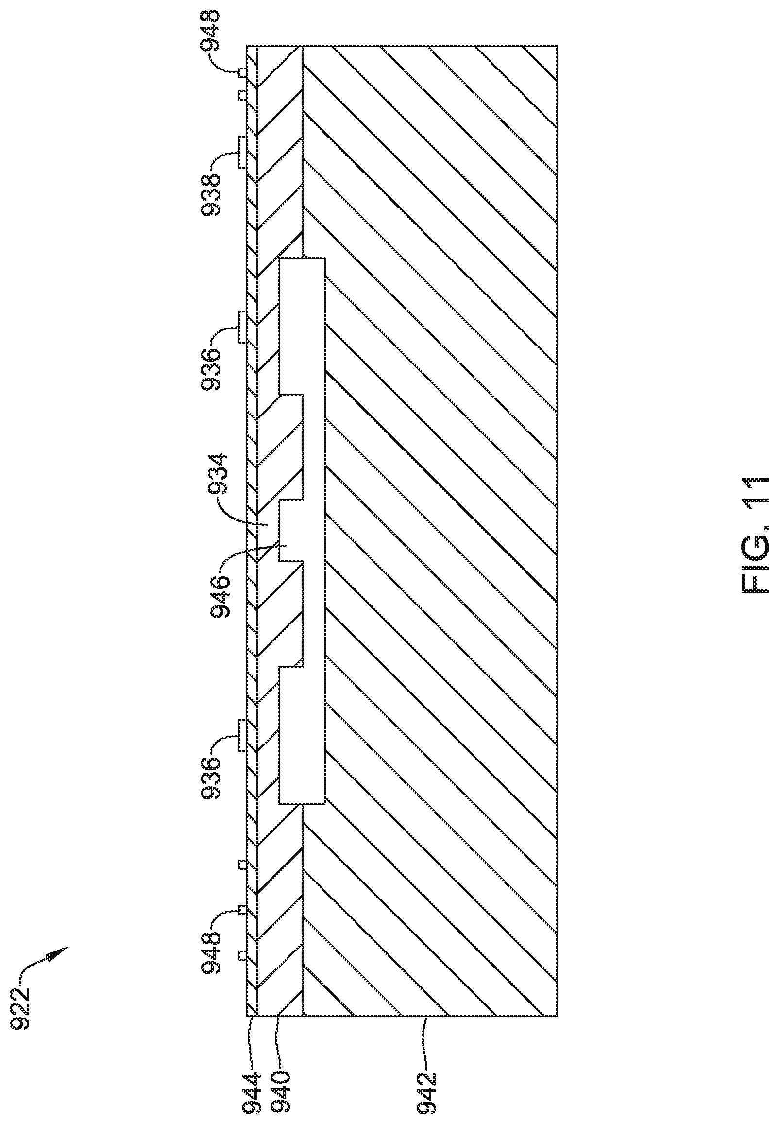
D00013

D00014

D00015
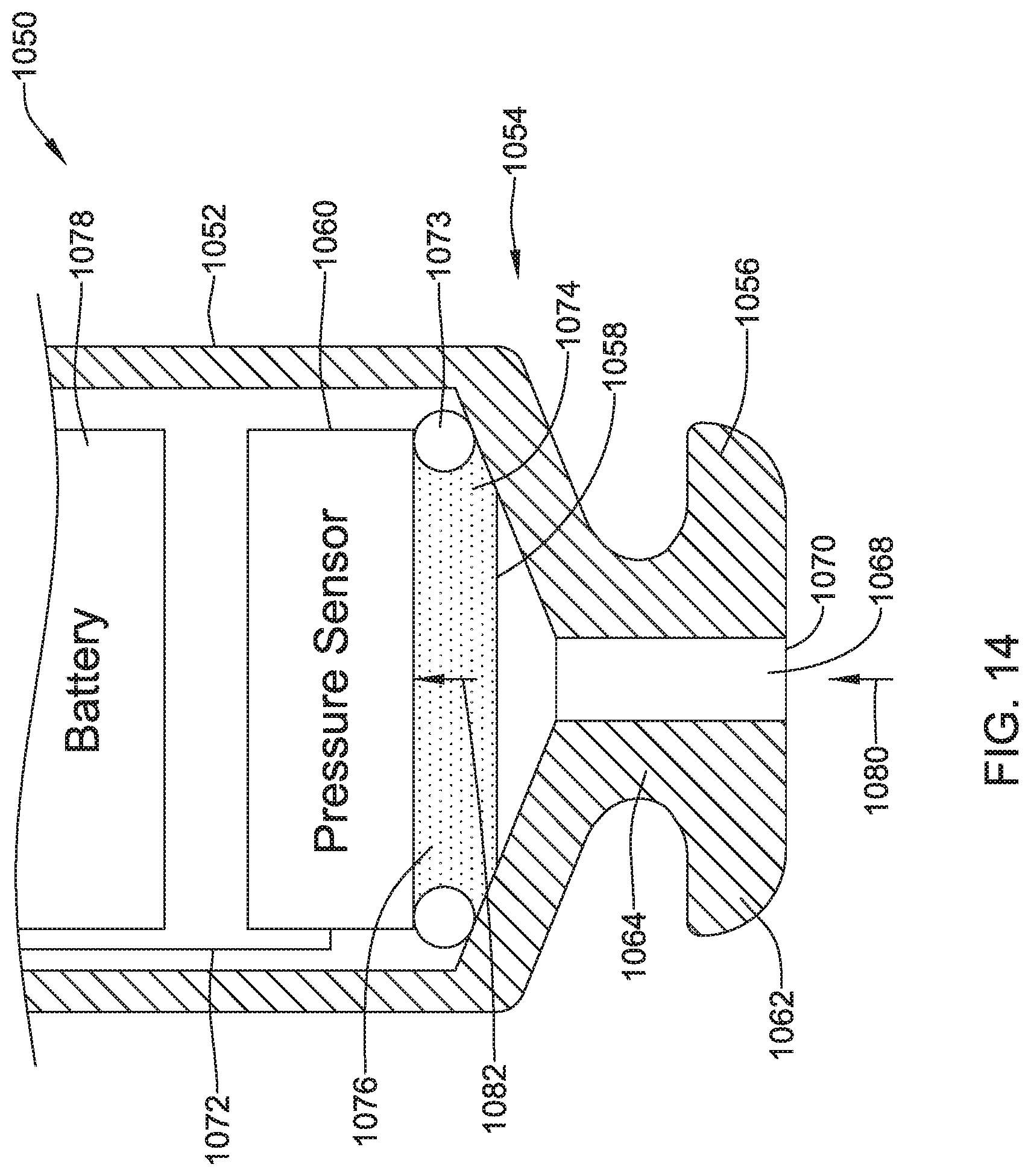
D00016

D00017
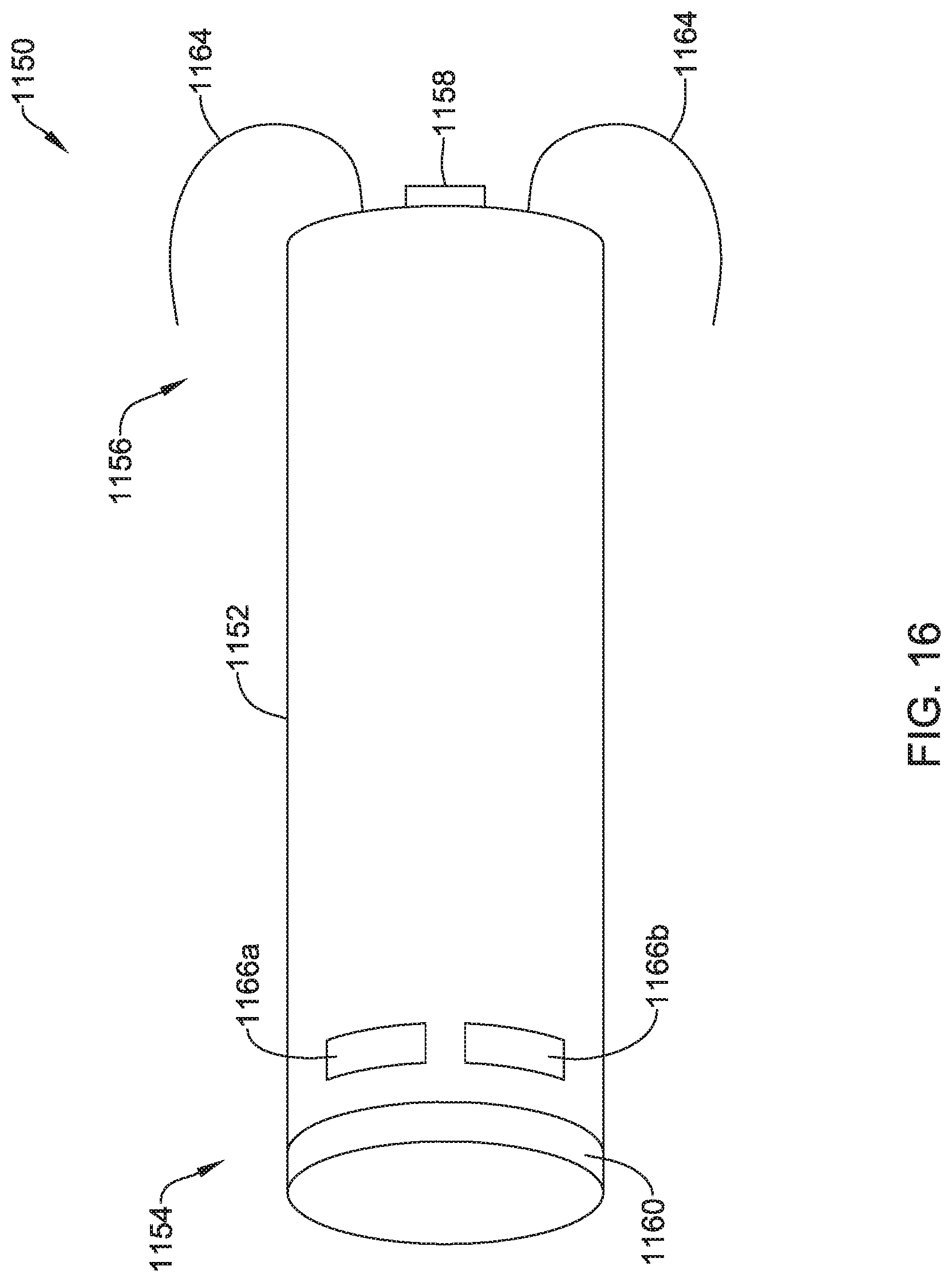
D00018

D00019
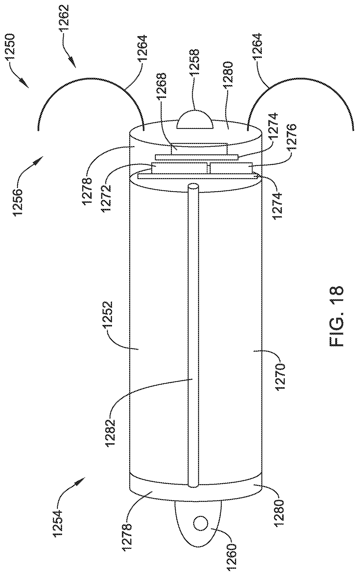
XML
uspto.report is an independent third-party trademark research tool that is not affiliated, endorsed, or sponsored by the United States Patent and Trademark Office (USPTO) or any other governmental organization. The information provided by uspto.report is based on publicly available data at the time of writing and is intended for informational purposes only.
While we strive to provide accurate and up-to-date information, we do not guarantee the accuracy, completeness, reliability, or suitability of the information displayed on this site. The use of this site is at your own risk. Any reliance you place on such information is therefore strictly at your own risk.
All official trademark data, including owner information, should be verified by visiting the official USPTO website at www.uspto.gov. This site is not intended to replace professional legal advice and should not be used as a substitute for consulting with a legal professional who is knowledgeable about trademark law.