Implantable medical device delivery system with integrated sensor
Koop , et al. Sep
U.S. patent number 10,758,724 [Application Number 15/793,149] was granted by the patent office on 2020-09-01 for implantable medical device delivery system with integrated sensor. This patent grant is currently assigned to CARDIAC PACEMAKERS, INC.. The grantee listed for this patent is CARDIAC PACEMAKERS, INC.. Invention is credited to Qi An, Viktoria A. Averina, Michael J. Kane, Brendan Early Koop, Keith R. Maile, Bin Mi, Arjun D. Sharma, Allan Charles Shuros, Krzysztof Z. Siejko, Brian Soltis, Jeffrey E. Stahmann, Pramodsingh Hirasingh Thakur, Yinghong Yu.


View All Diagrams
| United States Patent | 10,758,724 |
| Koop , et al. | September 1, 2020 |
Implantable medical device delivery system with integrated sensor
Abstract
A delivery and deployment device may include a handle assembly and a shaft extending distally from the handle assembly. A device containment housing may be coupled to a distal region of the shaft and may extend distally therefrom. The distal containment housing may be configured to accommodate at least a portion of the IMD therein. The IMD may, for example, be a leadless pacemaker, a lead, a neurostimulation device, a sensor or any other suitable IMD. A plurality of electrodes may be distributed about an exterior surface of the device containment housing such that at least some of the plurality of electrodes may be positioned to test a potential IMD deployment location before deploying the IMD.
| Inventors: | Koop; Brendan Early (Ham Lake, MN), Yu; Yinghong (Shoreview, MN), An; Qi (Blaine, MN), Maile; Keith R. (New Brighton, MN), Thakur; Pramodsingh Hirasingh (Woodbury, MN), Mi; Bin (Plymouth, MN), Stahmann; Jeffrey E. (Ramsey, MN), Averina; Viktoria A. (Shoreview, MN), Siejko; Krzysztof Z. (Maple Grove, MN), Kane; Michael J. (St. Paul, MN), Shuros; Allan Charles (St. Paul, MN), Sharma; Arjun D. (St. Paul, MN), Soltis; Brian (St. Paul, MN) | ||||||||||
|---|---|---|---|---|---|---|---|---|---|---|---|
| Applicant: |
|
||||||||||
| Assignee: | CARDIAC PACEMAKERS, INC. (St.
Paul, MN) |
||||||||||
| Family ID: | 60302471 | ||||||||||
| Appl. No.: | 15/793,149 | ||||||||||
| Filed: | October 25, 2017 |
Prior Publication Data
| Document Identifier | Publication Date | |
|---|---|---|
| US 20180117304 A1 | May 3, 2018 | |
Related U.S. Patent Documents
| Application Number | Filing Date | Patent Number | Issue Date | ||
|---|---|---|---|---|---|
| 62413748 | Oct 27, 2016 | ||||
| Current U.S. Class: | 1/1 |
| Current CPC Class: | A61B 5/0031 (20130101); A61B 5/686 (20130101); A61N 1/372 (20130101); A61N 1/056 (20130101); A61N 1/37288 (20130101); A61F 2/2436 (20130101); A61N 1/3756 (20130101); A61N 1/3706 (20130101) |
| Current International Class: | A61N 1/05 (20060101); A61B 5/00 (20060101); A61N 1/372 (20060101); A61N 1/375 (20060101); A61F 2/24 (20060101); A61N 1/37 (20060101) |
| Field of Search: | ;600/31 |
References Cited [Referenced By]
U.S. Patent Documents
| 3835864 | September 1974 | Rasor et al. |
| 3943936 | March 1976 | Rasor et al. |
| 4142530 | March 1979 | Wittkampf |
| 4151513 | April 1979 | Menken et al. |
| 4157720 | June 1979 | Greatbatch |
| RE30366 | August 1980 | Rasor et al. |
| 4243045 | January 1981 | Maas |
| 4250884 | February 1981 | Hartlaub et al. |
| 4256115 | March 1981 | Bilitch |
| 4263919 | April 1981 | Levin |
| 4310000 | January 1982 | Lindemans |
| 4312354 | January 1982 | Walters |
| 4323081 | April 1982 | Wiebusch |
| 4357946 | November 1982 | Dutcher et al. |
| 4365639 | December 1982 | Goldreyer |
| 4440173 | April 1984 | Hudziak et al. |
| 4476868 | October 1984 | Thompson |
| 4522208 | June 1985 | Buffet |
| 4537200 | August 1985 | Widrow |
| 4556063 | December 1985 | Thompson et al. |
| 4562841 | January 1986 | Brockway et al. |
| 4593702 | June 1986 | Kepski et al. |
| 4593955 | June 1986 | Leiber |
| 4630611 | December 1986 | King |
| 4635639 | January 1987 | Hakala et al. |
| 4674508 | June 1987 | DeCote |
| 4712554 | December 1987 | Garson |
| 4729376 | March 1988 | DeCote |
| 4754753 | July 1988 | King |
| 4759366 | July 1988 | Callaghan |
| 4776338 | October 1988 | Lekholm et al. |
| 4787389 | November 1988 | Tarjan |
| 4793353 | December 1988 | Borkan |
| 4819662 | April 1989 | Heil et al. |
| 4858610 | August 1989 | Callaghan et al. |
| 4886064 | December 1989 | Strandberg |
| 4887609 | December 1989 | Cole |
| 4928688 | May 1990 | Mower |
| 4967746 | November 1990 | Vandegriff |
| 4987897 | January 1991 | Funke |
| 4989602 | February 1991 | Sholder et al. |
| 5012806 | May 1991 | De Bellis |
| 5036849 | August 1991 | Hauck et al. |
| 5040534 | August 1991 | Mann et al. |
| 5058581 | October 1991 | Silvian |
| 5078134 | January 1992 | Heilman et al. |
| 5109845 | May 1992 | Yuuchi et al. |
| 5113859 | May 1992 | Funke |
| 5113869 | May 1992 | Nappholz et al. |
| 5117824 | June 1992 | Keimel et al. |
| 5127401 | July 1992 | Grevious et al. |
| 5133353 | July 1992 | Hauser |
| 5144950 | September 1992 | Stoop et al. |
| 5170784 | December 1992 | Ramon et al. |
| 5179945 | January 1993 | Van Hofwegen et al. |
| 5193539 | March 1993 | Schulman et al. |
| 5193540 | March 1993 | Schulman et al. |
| 5241961 | September 1993 | Henry |
| 5243977 | September 1993 | Trabucco et al. |
| 5259387 | November 1993 | DePinto |
| 5269326 | December 1993 | Verrier |
| 5284136 | February 1994 | Hauck et al. |
| 5300107 | April 1994 | Stokes et al. |
| 5301677 | April 1994 | Hsung |
| 5305760 | April 1994 | McKown et al. |
| 5312439 | May 1994 | Loeb |
| 5313953 | May 1994 | Yomtov et al. |
| 5314459 | May 1994 | Swanson et al. |
| 5318597 | June 1994 | Hauck et al. |
| 5324316 | June 1994 | Schulman et al. |
| 5331966 | July 1994 | Bennett et al. |
| 5334222 | August 1994 | Salo et al. |
| 5342408 | August 1994 | deCoriolis et al. |
| 5370667 | December 1994 | Alt |
| 5372606 | December 1994 | Lang et al. |
| 5376106 | December 1994 | Stahmann et al. |
| 5383915 | January 1995 | Adams |
| 5388578 | February 1995 | Yomtov et al. |
| 5404877 | April 1995 | Nolan et al. |
| 5405367 | April 1995 | Schulman et al. |
| 5411031 | May 1995 | Yomtov |
| 5411525 | May 1995 | Swanson et al. |
| 5411535 | May 1995 | Fujii et al. |
| 5456691 | October 1995 | Snell |
| 5458622 | October 1995 | Alt |
| 5466246 | November 1995 | Silvian |
| 5468254 | November 1995 | Hahn et al. |
| 5472453 | December 1995 | Alt |
| 5522866 | June 1996 | Fernald |
| 5540727 | July 1996 | Tockman et al. |
| 5545186 | August 1996 | Olson et al. |
| 5545202 | August 1996 | Dahl et al. |
| 5571146 | November 1996 | Jones et al. |
| 5591214 | January 1997 | Lu |
| 5620466 | April 1997 | Haefner et al. |
| 5634938 | June 1997 | Swanson et al. |
| 5649968 | July 1997 | Alt et al. |
| 5662688 | September 1997 | Haefner et al. |
| 5674259 | October 1997 | Gray |
| 5683426 | November 1997 | Greenhut et al. |
| 5683432 | November 1997 | Goedeke et al. |
| 5706823 | January 1998 | Wodlinger |
| 5709215 | January 1998 | Perttu et al. |
| 5720770 | February 1998 | Nappholz et al. |
| 5728154 | March 1998 | Crossett et al. |
| 5741314 | April 1998 | Daly et al. |
| 5741315 | April 1998 | Lee et al. |
| 5752976 | May 1998 | Duffin et al. |
| 5752977 | May 1998 | Grevious et al. |
| 5755736 | May 1998 | Gillberg et al. |
| 5759199 | June 1998 | Snell et al. |
| 5774501 | June 1998 | Halpern et al. |
| 5792195 | August 1998 | Carlson et al. |
| 5792202 | August 1998 | Rueter |
| 5792203 | August 1998 | Schroeppel |
| 5792205 | August 1998 | Alt et al. |
| 5792208 | August 1998 | Gray |
| 5814089 | September 1998 | Stokes et al. |
| 5827216 | October 1998 | Igo et al. |
| 5836985 | November 1998 | Rostami et al. |
| 5836987 | November 1998 | Baumann et al. |
| 5842977 | December 1998 | Lesho et al. |
| 5855593 | January 1999 | Olson et al. |
| 5873894 | February 1999 | Vandegriff et al. |
| 5891184 | April 1999 | Lee et al. |
| 5897586 | April 1999 | Molina |
| 5899876 | May 1999 | Flower |
| 5899928 | May 1999 | Sholder et al. |
| 5919214 | July 1999 | Ciciarelli et al. |
| 5935078 | August 1999 | Feierbach |
| 5941906 | August 1999 | Barreras, Sr. et al. |
| 5944744 | August 1999 | Paul et al. |
| 5954757 | September 1999 | Gray |
| 5978713 | November 1999 | Prutchi et al. |
| 5991660 | November 1999 | Goyal |
| 5991661 | November 1999 | Park et al. |
| 5999848 | December 1999 | Gord et al. |
| 5999857 | December 1999 | Weijand et al. |
| 6016445 | January 2000 | Baura |
| 6026320 | February 2000 | Carlson et al. |
| 6029085 | February 2000 | Olson et al. |
| 6041250 | March 2000 | DePinto |
| 6044298 | March 2000 | Salo et al. |
| 6044300 | March 2000 | Gray |
| 6055454 | April 2000 | Heemels |
| 6073050 | June 2000 | Griffith |
| 6076016 | June 2000 | Feierbach |
| 6077236 | June 2000 | Cunningham |
| 6080187 | June 2000 | Alt et al. |
| 6083248 | July 2000 | Thompson |
| 6106551 | August 2000 | Crossett et al. |
| 6115636 | September 2000 | Ryan |
| 6128526 | October 2000 | Stadler et al. |
| 6141581 | October 2000 | Olson et al. |
| 6141588 | October 2000 | Cox et al. |
| 6141592 | October 2000 | Pauly |
| 6144879 | November 2000 | Gray |
| 6162195 | December 2000 | Igo et al. |
| 6164284 | December 2000 | Schulman et al. |
| 6167310 | December 2000 | Grevious |
| 6201993 | March 2001 | Kruse et al. |
| 6208894 | March 2001 | Schulman et al. |
| 6211799 | April 2001 | Post et al. |
| 6221011 | April 2001 | Bardy |
| 6240316 | May 2001 | Richmond et al. |
| 6240317 | May 2001 | Villaseca et al. |
| 6256534 | July 2001 | Dahl |
| 6259947 | July 2001 | Olson et al. |
| 6266558 | July 2001 | Gozani et al. |
| 6266567 | July 2001 | Ishikawa et al. |
| 6270457 | August 2001 | Bardy |
| 6272377 | August 2001 | Sweeney et al. |
| 6273856 | August 2001 | Sun et al. |
| 6277072 | August 2001 | Bardy |
| 6280380 | August 2001 | Bardy |
| 6285907 | September 2001 | Kramer et al. |
| 6292698 | September 2001 | Duffin et al. |
| 6295473 | September 2001 | Rosar |
| 6297943 | October 2001 | Carson |
| 6298271 | October 2001 | Weijand |
| 6307751 | October 2001 | Bodony et al. |
| 6312378 | November 2001 | Bardy |
| 6315721 | November 2001 | Schulman et al. |
| 6336903 | January 2002 | Bardy |
| 6345202 | February 2002 | Richmond et al. |
| 6351667 | February 2002 | Godie |
| 6351669 | February 2002 | Hartley et al. |
| 6353759 | March 2002 | Hartley et al. |
| 6358203 | March 2002 | Bardy |
| 6361780 | March 2002 | Ley et al. |
| 6368284 | April 2002 | Bardy |
| 6371922 | April 2002 | Baumann et al. |
| 6398728 | June 2002 | Bardy |
| 6400982 | June 2002 | Sweeney et al. |
| 6400990 | June 2002 | Silvian |
| 6408208 | June 2002 | Sun |
| 6409674 | June 2002 | Brockway et al. |
| 6411848 | June 2002 | Kramer et al. |
| 6424865 | July 2002 | Ding |
| 6434429 | August 2002 | Kraus et al. |
| 6438410 | August 2002 | Hsu et al. |
| 6438417 | August 2002 | Rockwell et al. |
| 6438421 | August 2002 | Stahmann et al. |
| 6440066 | August 2002 | Bardy |
| 6441747 | August 2002 | Khair et al. |
| 6442426 | August 2002 | Kroll |
| 6442432 | August 2002 | Lee |
| 6443891 | September 2002 | Grevious |
| 6445953 | September 2002 | Bulkes et al. |
| 6453200 | September 2002 | Koslar |
| 6459929 | October 2002 | Hopper et al. |
| 6470215 | October 2002 | Kraus et al. |
| 6471645 | October 2002 | Warkentin et al. |
| 6480745 | November 2002 | Nelson et al. |
| 6487443 | November 2002 | Olson et al. |
| 6490487 | December 2002 | Kraus et al. |
| 6498951 | December 2002 | Larson et al. |
| 6507755 | January 2003 | Gozani et al. |
| 6507759 | January 2003 | Prutchi et al. |
| 6512940 | January 2003 | Brabec et al. |
| 6522915 | February 2003 | Ceballos et al. |
| 6526311 | February 2003 | Begemann |
| 6539253 | March 2003 | Thompson et al. |
| 6542775 | April 2003 | Ding et al. |
| 6553258 | April 2003 | Stahmann et al. |
| 6561975 | May 2003 | Pool et al. |
| 6564807 | May 2003 | Schulman et al. |
| 6574506 | June 2003 | Kramer et al. |
| 6584351 | June 2003 | Ekwall |
| 6584352 | June 2003 | Combs et al. |
| 6597948 | July 2003 | Rockwell et al. |
| 6597951 | July 2003 | Kramer et al. |
| 6622046 | September 2003 | Fraley et al. |
| 6628985 | September 2003 | Sweeney et al. |
| 6647292 | November 2003 | Bardy et al. |
| 6666844 | December 2003 | Igo et al. |
| 6689117 | February 2004 | Sweeney et al. |
| 6690959 | February 2004 | Thompson |
| 6694189 | February 2004 | Begemann |
| 6704602 | March 2004 | Berg et al. |
| 6718212 | April 2004 | Parry et al. |
| 6721597 | April 2004 | Bardy et al. |
| 6738670 | May 2004 | Almendinger et al. |
| 6746797 | June 2004 | Benson et al. |
| 6749566 | June 2004 | Russ |
| 6758810 | July 2004 | Lebel et al. |
| 6763269 | July 2004 | Cox |
| 6778860 | August 2004 | Ostroff et al. |
| 6788971 | September 2004 | Sloman et al. |
| 6788974 | September 2004 | Bardy et al. |
| 6804558 | October 2004 | Haller et al. |
| 6807442 | October 2004 | Myklebust et al. |
| 6847844 | January 2005 | Sun et al. |
| 6871095 | March 2005 | Stahmann et al. |
| 6878112 | April 2005 | Linberg et al. |
| 6885889 | April 2005 | Chinchoy |
| 6892094 | May 2005 | Ousdigian et al. |
| 6897788 | May 2005 | Khair et al. |
| 6904315 | June 2005 | Panken et al. |
| 6922592 | July 2005 | Thompson et al. |
| 6931282 | August 2005 | Esler |
| 6934585 | August 2005 | Schloss et al. |
| 6957107 | October 2005 | Rogers et al. |
| 6978176 | December 2005 | Lattouf |
| 6985773 | January 2006 | Von Arx et al. |
| 6990375 | January 2006 | Kloss et al. |
| 7001366 | February 2006 | Ballard |
| 7003350 | February 2006 | Denker et al. |
| 7006864 | February 2006 | Echt et al. |
| 7013178 | March 2006 | Reinke et al. |
| 7027871 | April 2006 | Burnes et al. |
| 7050849 | May 2006 | Echt et al. |
| 7060031 | June 2006 | Webb et al. |
| 7063693 | June 2006 | Guenst |
| 7082336 | July 2006 | Ransbury et al. |
| 7085606 | August 2006 | Flach et al. |
| 7092758 | August 2006 | Sun et al. |
| 7110824 | September 2006 | Amundson et al. |
| 7120504 | October 2006 | Osypka |
| 7130681 | October 2006 | Gebhardt et al. |
| 7139613 | November 2006 | Reinke et al. |
| 7142912 | November 2006 | Wagner et al. |
| 7146225 | December 2006 | Guenst et al. |
| 7146226 | December 2006 | Lau et al. |
| 7149581 | December 2006 | Goedeke |
| 7149588 | December 2006 | Lau et al. |
| 7158839 | January 2007 | Lau |
| 7162307 | January 2007 | Patrias |
| 7164952 | January 2007 | Lau et al. |
| 7177700 | February 2007 | Cox |
| 7181505 | February 2007 | Haller et al. |
| 7184830 | February 2007 | Echt et al. |
| 7186214 | March 2007 | Ness |
| 7191015 | March 2007 | Lamson et al. |
| 7200437 | April 2007 | Nabutovsky et al. |
| 7200439 | April 2007 | Zdeblick et al. |
| 7206423 | April 2007 | Feng et al. |
| 7209785 | April 2007 | Kim et al. |
| 7209790 | April 2007 | Thompson et al. |
| 7211884 | May 2007 | Davis et al. |
| 7212871 | May 2007 | Morgan |
| 7226440 | June 2007 | Gelfand et al. |
| 7228183 | June 2007 | Sun et al. |
| 7236821 | June 2007 | Cates et al. |
| 7236829 | June 2007 | Farazi et al. |
| 7254448 | August 2007 | Almendinger et al. |
| 7260436 | August 2007 | Kilgore et al. |
| 7270669 | September 2007 | Sra |
| 7272448 | September 2007 | Morgan et al. |
| 7277755 | October 2007 | Falkenberg et al. |
| 7280872 | October 2007 | Mosesov et al. |
| 7288096 | October 2007 | Chin |
| 7289847 | October 2007 | Gill et al. |
| 7289852 | October 2007 | Helfinstine et al. |
| 7289853 | October 2007 | Campbell et al. |
| 7289855 | October 2007 | Nghiem et al. |
| 7302294 | November 2007 | Kamath et al. |
| 7305266 | December 2007 | Kroll |
| 7310556 | December 2007 | Bulkes |
| 7319905 | January 2008 | Morgan et al. |
| 7321798 | January 2008 | Muhlenberg et al. |
| 7333853 | February 2008 | Mazar et al. |
| 7336994 | February 2008 | Hettrick et al. |
| 7347819 | March 2008 | Lebel et al. |
| 7366572 | April 2008 | Heruth et al. |
| 7373207 | May 2008 | Lattouf |
| 7384403 | June 2008 | Sherman |
| 7386342 | June 2008 | Falkenberg et al. |
| 7392090 | June 2008 | Sweeney et al. |
| 7406105 | July 2008 | DelMain et al. |
| 7406349 | July 2008 | Seeberger et al. |
| 7410497 | August 2008 | Hastings et al. |
| 7425200 | September 2008 | Brockway et al. |
| 7433739 | October 2008 | Salys et al. |
| 7496409 | February 2009 | Greenhut et al. |
| 7496410 | February 2009 | Heil |
| 7502652 | March 2009 | Gaunt et al. |
| 7512448 | March 2009 | Malick et al. |
| 7515969 | April 2009 | Tockman et al. |
| 7526342 | April 2009 | Chin et al. |
| 7529589 | May 2009 | Williams et al. |
| 7532933 | May 2009 | Hastings et al. |
| 7536222 | May 2009 | Bardy et al. |
| 7536224 | May 2009 | Ritscher et al. |
| 7539541 | May 2009 | Quiles et al. |
| 7544197 | June 2009 | Kelsch et al. |
| 7558631 | July 2009 | Cowan et al. |
| 7565195 | July 2009 | Kroll et al. |
| 7584002 | September 2009 | Burnes et al. |
| 7590455 | September 2009 | Heruth et al. |
| 7606621 | October 2009 | Brisken et al. |
| 7610088 | October 2009 | Chinchoy |
| 7610092 | October 2009 | Cowan et al. |
| 7610099 | October 2009 | Almendinger et al. |
| 7610104 | October 2009 | Kaplan et al. |
| 7616991 | November 2009 | Mann et al. |
| 7617001 | November 2009 | Penner et al. |
| 7617007 | November 2009 | Williams et al. |
| 7630767 | December 2009 | Poore et al. |
| 7634313 | December 2009 | Kroll et al. |
| 7637867 | December 2009 | Zdeblick |
| 7640060 | December 2009 | Zdeblick |
| 7647109 | January 2010 | Hastings et al. |
| 7650186 | January 2010 | Hastings et al. |
| 7657311 | February 2010 | Bardy et al. |
| 7668596 | February 2010 | Von Arx et al. |
| 7682316 | March 2010 | Anderson et al. |
| 7691047 | April 2010 | Ferrari |
| 7702392 | April 2010 | Echt et al. |
| 7713194 | May 2010 | Zdeblick |
| 7713195 | May 2010 | Zdeblick |
| 7729783 | June 2010 | Michels et al. |
| 7734333 | June 2010 | Ghanem et al. |
| 7734343 | June 2010 | Ransbury et al. |
| 7738958 | June 2010 | Zdeblick et al. |
| 7738964 | June 2010 | Von Arx et al. |
| 7742812 | June 2010 | Ghanem et al. |
| 7742816 | June 2010 | Masoud et al. |
| 7742822 | June 2010 | Masoud et al. |
| 7743151 | June 2010 | Vallapureddy et al. |
| 7747335 | June 2010 | Williams |
| 7751881 | July 2010 | Cowan et al. |
| 7758521 | July 2010 | Morris et al. |
| 7761150 | July 2010 | Ghanem et al. |
| 7761164 | July 2010 | Verhoef et al. |
| 7765001 | July 2010 | Echt et al. |
| 7769452 | August 2010 | Ghanem et al. |
| 7783362 | August 2010 | Whitehurst et al. |
| 7792588 | September 2010 | Harding |
| 7797059 | September 2010 | Bornzin et al. |
| 7801596 | September 2010 | Fischell et al. |
| 7809438 | October 2010 | Echt et al. |
| 7840281 | November 2010 | Kveen et al. |
| 7844331 | November 2010 | Li et al. |
| 7844348 | November 2010 | Swoyer et al. |
| 7846088 | December 2010 | Ness |
| 7848815 | December 2010 | Brisken et al. |
| 7848823 | December 2010 | Drasler et al. |
| 7860455 | December 2010 | Fukumoto et al. |
| 7871433 | January 2011 | Lattouf |
| 7877136 | January 2011 | Moffitt et al. |
| 7877142 | January 2011 | Moaddeb et al. |
| 7881786 | February 2011 | Jackson |
| 7881798 | February 2011 | Miesel et al. |
| 7881810 | February 2011 | Chitre et al. |
| 7890173 | February 2011 | Brisken et al. |
| 7890181 | February 2011 | Denzene et al. |
| 7890192 | February 2011 | Kelsch et al. |
| 7894885 | February 2011 | Bartal et al. |
| 7894894 | February 2011 | Stadler et al. |
| 7894907 | February 2011 | Cowan et al. |
| 7894910 | February 2011 | Cowan et al. |
| 7894915 | February 2011 | Chitre et al. |
| 7899537 | March 2011 | Kroll et al. |
| 7899541 | March 2011 | Cowan et al. |
| 7899542 | March 2011 | Cowan et al. |
| 7899554 | March 2011 | Williams et al. |
| 7901360 | March 2011 | Yang et al. |
| 7904170 | March 2011 | Harding |
| 7907993 | March 2011 | Ghanem et al. |
| 7920928 | April 2011 | Yang et al. |
| 7925343 | April 2011 | Min et al. |
| 7930022 | April 2011 | Zhang et al. |
| 7930040 | April 2011 | Kelsch et al. |
| 7937135 | May 2011 | Ghanem et al. |
| 7937148 | May 2011 | Jacobson |
| 7937161 | May 2011 | Hastings et al. |
| 7941214 | May 2011 | Kleckner et al. |
| 7945333 | May 2011 | Jacobson |
| 7946997 | May 2011 | Hubinette |
| 7949404 | May 2011 | Hill |
| 7949405 | May 2011 | Feher |
| 7953486 | May 2011 | Daum et al. |
| 7953493 | May 2011 | Fowler et al. |
| 7962202 | June 2011 | Bhunia |
| 7974702 | July 2011 | Fain et al. |
| 7979136 | July 2011 | Young et al. |
| 7983753 | July 2011 | Severin |
| 7991467 | August 2011 | Markowitz et al. |
| 7991471 | August 2011 | Ghanem et al. |
| 7996087 | August 2011 | Cowan et al. |
| 8000791 | August 2011 | Sunagawa et al. |
| 8000807 | August 2011 | Morris et al. |
| 8001975 | August 2011 | DiSilvestro et al. |
| 8002700 | August 2011 | Ferek-Petric et al. |
| 8010209 | August 2011 | Jacobson |
| 8019419 | September 2011 | Panescu et al. |
| 8019434 | September 2011 | Quiles et al. |
| 8027727 | September 2011 | Freeberg |
| 8027729 | September 2011 | Sunagawa et al. |
| 8032219 | October 2011 | Neumann et al. |
| 8036743 | October 2011 | Savage et al. |
| 8046079 | October 2011 | Bange et al. |
| 8046080 | October 2011 | Von Arx et al. |
| 8050297 | November 2011 | DelMain et al. |
| 8050759 | November 2011 | Stegemann et al. |
| 8050774 | November 2011 | Kveen et al. |
| 8055345 | November 2011 | Li et al. |
| 8055350 | November 2011 | Roberts |
| 8060212 | November 2011 | Rios et al. |
| 8065018 | November 2011 | Haubrich et al. |
| 8073542 | December 2011 | Doerr |
| 8078278 | December 2011 | Penner |
| 8078283 | December 2011 | Cowan et al. |
| 8095123 | January 2012 | Gray |
| 8102789 | January 2012 | Rosar et al. |
| 8103359 | January 2012 | Reddy |
| 8103361 | January 2012 | Moser |
| 8112148 | February 2012 | Giftakis et al. |
| 8114021 | February 2012 | Robertson et al. |
| 8121680 | February 2012 | Falkenberg et al. |
| 8123684 | February 2012 | Zdeblick |
| 8126545 | February 2012 | Flach et al. |
| 8131334 | March 2012 | Lu et al. |
| 8140161 | March 2012 | Willerton et al. |
| 8150521 | April 2012 | Crowley et al. |
| 8160672 | April 2012 | Kim et al. |
| 8160702 | April 2012 | Mann et al. |
| 8160704 | April 2012 | Freeberg |
| 8165694 | April 2012 | Carbanaru et al. |
| 8175715 | May 2012 | Cox |
| 8180451 | May 2012 | Hickman et al. |
| 8185213 | May 2012 | Kveen et al. |
| 8187161 | May 2012 | Li et al. |
| 8195293 | June 2012 | Limousin et al. |
| 8204595 | June 2012 | Pianca et al. |
| 8204605 | June 2012 | Hastings et al. |
| 8209014 | June 2012 | Doerr |
| 8214043 | July 2012 | Matos |
| 8224244 | July 2012 | Kim et al. |
| 8229556 | July 2012 | Li |
| 8233985 | July 2012 | Bulkes et al. |
| 8262578 | September 2012 | Bharmi et al. |
| 8265748 | September 2012 | Liu et al. |
| 8265757 | September 2012 | Mass et al. |
| 8280521 | October 2012 | Haubrich et al. |
| 8285387 | October 2012 | Utsi et al. |
| 8290598 | October 2012 | Boon et al. |
| 8290600 | October 2012 | Hastings et al. |
| 8295939 | October 2012 | Jacobson |
| 8301254 | October 2012 | Mosesov et al. |
| 8315701 | November 2012 | Cowan et al. |
| 8315708 | November 2012 | Berthelsdorf et al. |
| 8321021 | November 2012 | Kisker et al. |
| 8321036 | November 2012 | Brockway et al. |
| 8332036 | December 2012 | Hastings et al. |
| 8335563 | December 2012 | Stessman |
| 8335568 | December 2012 | Heruth et al. |
| 8340750 | December 2012 | Prakash et al. |
| 8340780 | December 2012 | Hastings et al. |
| 8352025 | January 2013 | Jacobson |
| 8352028 | January 2013 | Wenger |
| 8352038 | January 2013 | Mao et al. |
| 8359098 | January 2013 | Lund et al. |
| 8364261 | January 2013 | Stubbs et al. |
| 8364276 | January 2013 | Willis |
| 8369959 | February 2013 | Meskens |
| 8369962 | February 2013 | Abrahamson |
| 8380320 | February 2013 | Spital |
| 8386051 | February 2013 | Rys |
| 8391981 | March 2013 | Mosesov |
| 8391990 | March 2013 | Smith et al. |
| 8406874 | March 2013 | Liu et al. |
| 8406879 | March 2013 | Shuros et al. |
| 8406886 | March 2013 | Gaunt et al. |
| 8412352 | April 2013 | Griswold et al. |
| 8417340 | April 2013 | Goossen |
| 8417341 | April 2013 | Freeberg |
| 8423149 | April 2013 | Hennig |
| 8428722 | April 2013 | Verhoef et al. |
| 8433402 | April 2013 | Ruben et al. |
| 8433409 | April 2013 | Johnson et al. |
| 8433420 | April 2013 | Bange et al. |
| 8447412 | May 2013 | Dal Molin et al. |
| 8452413 | May 2013 | Young et al. |
| 8457740 | June 2013 | Osche |
| 8457742 | June 2013 | Jacobson |
| 8457744 | June 2013 | Janzig et al. |
| 8457761 | June 2013 | Wariar |
| 8478407 | July 2013 | Demmer et al. |
| 8478408 | July 2013 | Hastings et al. |
| 8478431 | July 2013 | Griswold et al. |
| 8494632 | July 2013 | Sun et al. |
| 8504156 | August 2013 | Bonner et al. |
| 8509910 | August 2013 | Sowder et al. |
| 8515559 | August 2013 | Roberts et al. |
| 8525340 | September 2013 | Eckhardt et al. |
| 8527068 | September 2013 | Ostroff |
| 8532790 | September 2013 | Griswold |
| 8538526 | September 2013 | Stahmann et al. |
| 8541131 | September 2013 | Lund et al. |
| 8543205 | September 2013 | Ostroff |
| 8547248 | October 2013 | Zdeblick et al. |
| 8548605 | October 2013 | Ollivier |
| 8554333 | October 2013 | Wu et al. |
| 8565882 | October 2013 | Matos |
| 8565897 | October 2013 | Regnier et al. |
| 8571678 | October 2013 | Wang |
| 8577327 | November 2013 | Makdissi et al. |
| 8588926 | November 2013 | Moore et al. |
| 8612002 | December 2013 | Faltys et al. |
| 8615310 | December 2013 | Khairkhahan et al. |
| 8626280 | January 2014 | Allavatam et al. |
| 8626294 | January 2014 | Sheldon et al. |
| 8634908 | January 2014 | Cowan |
| 8634912 | January 2014 | Bornzin et al. |
| 8634919 | January 2014 | Hou et al. |
| 8639335 | January 2014 | Peichel et al. |
| 8644934 | February 2014 | Hastings et al. |
| 8649859 | February 2014 | Smith et al. |
| 8670842 | March 2014 | Bornzin et al. |
| 8676319 | March 2014 | Knoll |
| 8676335 | March 2014 | Katoozi et al. |
| 8700173 | April 2014 | Edlund |
| 8700181 | April 2014 | Bornzin et al. |
| 8705599 | April 2014 | dal Molin et al. |
| 8718766 | May 2014 | Wahlberg |
| 8718773 | May 2014 | Willis et al. |
| 8725260 | May 2014 | Shuros et al. |
| 8738133 | May 2014 | Shuros et al. |
| 8738147 | May 2014 | Hastings et al. |
| 8744555 | June 2014 | Allavatam et al. |
| 8744572 | June 2014 | Greenhut et al. |
| 8747314 | June 2014 | Stahmann et al. |
| 8755884 | June 2014 | Demmer et al. |
| 8758365 | June 2014 | Bonner et al. |
| 8768483 | July 2014 | Schmitt et al. |
| 8774572 | July 2014 | Hamamoto |
| 8781605 | July 2014 | Bornzin et al. |
| 8788035 | July 2014 | Jacobson |
| 8788053 | July 2014 | Jacobson |
| 8798740 | August 2014 | Samade et al. |
| 8798745 | August 2014 | Jacobson |
| 8798762 | August 2014 | Fain et al. |
| 8798770 | August 2014 | Reddy |
| 8805505 | August 2014 | Roberts |
| 8805528 | August 2014 | Corndorf |
| 8812109 | August 2014 | Blomqvist et al. |
| 8818504 | August 2014 | Bodner et al. |
| 8827913 | September 2014 | Havel et al. |
| 8831747 | September 2014 | Min et al. |
| 8855789 | October 2014 | Jacobson |
| 8868186 | October 2014 | Kroll |
| 8886339 | November 2014 | Faltys et al. |
| 8903473 | December 2014 | Rogers et al. |
| 8903500 | December 2014 | Smith et al. |
| 8903513 | December 2014 | Ollivier |
| 8909336 | December 2014 | Navarro-Paredes et al. |
| 8914131 | December 2014 | Bornzin et al. |
| 8923795 | December 2014 | Makdissi et al. |
| 8923963 | December 2014 | Bonner et al. |
| 8938300 | January 2015 | Rosero |
| 8942806 | January 2015 | Sheldon et al. |
| 8958892 | February 2015 | Khairkhahan et al. |
| 8977358 | March 2015 | Ewert et al. |
| 8989873 | March 2015 | Locsin |
| 8996109 | March 2015 | Karst et al. |
| 9002467 | April 2015 | Smith et al. |
| 9008776 | April 2015 | Cowan et al. |
| 9008777 | April 2015 | Dianaty et al. |
| 9014818 | April 2015 | Deterre et al. |
| 9017341 | April 2015 | Bornzin et al. |
| 9020611 | April 2015 | Khairkhahan et al. |
| 9037262 | May 2015 | Regnier et al. |
| 9042984 | May 2015 | Demmer et al. |
| 9072911 | July 2015 | Hastings et al. |
| 9072913 | July 2015 | Jacobson |
| 9072914 | July 2015 | Greenhut et al. |
| 9101281 | August 2015 | Reinert et al. |
| 9155882 | October 2015 | Grubac et al. |
| 9168372 | October 2015 | Fain |
| 9168380 | October 2015 | Greenhut et al. |
| 9168383 | October 2015 | Jacobson et al. |
| 9180285 | November 2015 | Moore et al. |
| 9192774 | November 2015 | Jacobson |
| 9205225 | December 2015 | Khairkhahan et al. |
| 9216285 | December 2015 | Boling et al. |
| 9216293 | December 2015 | Berthiaume et al. |
| 9216298 | December 2015 | Jacobson |
| 9227077 | January 2016 | Jacobson |
| 9238145 | January 2016 | Wenzel et al. |
| 9242102 | January 2016 | Khairkhahan et al. |
| 9242113 | January 2016 | Smith et al. |
| 9248300 | February 2016 | Rys et al. |
| 9265436 | February 2016 | Min et al. |
| 9265962 | February 2016 | Dianaty et al. |
| 9272155 | March 2016 | Ostroff |
| 9278218 | March 2016 | Karst et al. |
| 9278229 | March 2016 | Reinke et al. |
| 9283381 | March 2016 | Grubac et al. |
| 9283382 | March 2016 | Berthiaume et al. |
| 9289612 | March 2016 | Sambelashvili et al. |
| 9302115 | April 2016 | Molin et al. |
| 9308365 | April 2016 | Nordstrom et al. |
| 9333364 | May 2016 | Echt et al. |
| 9358387 | June 2016 | Suwito et al. |
| 9358400 | June 2016 | Jacobson |
| 9364675 | June 2016 | Deterre et al. |
| 9370663 | June 2016 | Moulder |
| 9375580 | June 2016 | Bonner et al. |
| 9375581 | June 2016 | Baru et al. |
| 9381365 | July 2016 | Kibler et al. |
| 9393424 | July 2016 | Demmer et al. |
| 9393436 | July 2016 | Doerr |
| 9399139 | July 2016 | Demmer et al. |
| 9399140 | July 2016 | Cho et al. |
| 9409033 | August 2016 | Jacobson |
| 9427594 | August 2016 | Bornzin et al. |
| 9433368 | September 2016 | Stahmann et al. |
| 9433780 | September 2016 | Regnier et al. |
| 9457193 | October 2016 | Klimovitch et al. |
| 9492668 | November 2016 | Sheldon et al. |
| 9492669 | November 2016 | Demmer et al. |
| 9492674 | November 2016 | Schmidt et al. |
| 9492677 | November 2016 | Greenhut et al. |
| 9511233 | December 2016 | Sambelashvili |
| 9511236 | December 2016 | Varady et al. |
| 9511237 | December 2016 | Deterre et al. |
| 9522276 | December 2016 | Shen et al. |
| 9522280 | December 2016 | Fishler et al. |
| 9526522 | December 2016 | Wood et al. |
| 9526891 | December 2016 | Eggen et al. |
| 9526909 | December 2016 | Stahmann et al. |
| 9533163 | January 2017 | Klimovitch et al. |
| 9561382 | February 2017 | Persson et al. |
| 9566012 | February 2017 | Greenhut et al. |
| 9636511 | May 2017 | Carney et al. |
| 9669223 | June 2017 | Auricchio et al. |
| 9687654 | June 2017 | Sheldon et al. |
| 9687655 | June 2017 | Pertijs et al. |
| 9687659 | June 2017 | Von Arx et al. |
| 9694186 | July 2017 | Carney et al. |
| 9782594 | October 2017 | Stahmann et al. |
| 9782601 | October 2017 | Ludwig |
| 9789317 | October 2017 | Greenhut et al. |
| 9789319 | October 2017 | Sambelashvili |
| 9808617 | November 2017 | Ostroff et al. |
| 9808628 | November 2017 | Sheldon et al. |
| 9808631 | November 2017 | Maile et al. |
| 9808632 | November 2017 | Reinke et al. |
| 9808633 | November 2017 | Bonner et al. |
| 9808637 | November 2017 | Sharma et al. |
| 9855414 | January 2018 | Marshall et al. |
| 9855430 | January 2018 | Ghosh et al. |
| 9855435 | January 2018 | Sahabi et al. |
| 9861815 | January 2018 | Tran et al. |
| 10080887 | September 2018 | Schmidt et al. |
| 10080888 | September 2018 | Kelly et al. |
| 10080900 | September 2018 | Ghosh et al. |
| 10080903 | September 2018 | Willis et al. |
| 10086206 | October 2018 | Sambelashvili |
| 2002/0032470 | March 2002 | Linberg |
| 2002/0035376 | March 2002 | Bardy et al. |
| 2002/0035377 | March 2002 | Bardy et al. |
| 2002/0035378 | March 2002 | Bardy et al. |
| 2002/0035380 | March 2002 | Rissmann et al. |
| 2002/0035381 | March 2002 | Bardy et al. |
| 2002/0042629 | April 2002 | Bardy et al. |
| 2002/0042630 | April 2002 | Bardy et al. |
| 2002/0042634 | April 2002 | Bardy et al. |
| 2002/0049475 | April 2002 | Bardy et al. |
| 2002/0052636 | May 2002 | Bardy et al. |
| 2002/0068958 | June 2002 | Bardy et al. |
| 2002/0072773 | June 2002 | Bardy et al. |
| 2002/0082665 | June 2002 | Haller et al. |
| 2002/0087089 | July 2002 | Ben-Haim |
| 2002/0091414 | July 2002 | Bardy et al. |
| 2002/0095196 | July 2002 | Linberg |
| 2002/0099423 | July 2002 | Berg et al. |
| 2002/0103510 | August 2002 | Bardy et al. |
| 2002/0107545 | August 2002 | Rissmann et al. |
| 2002/0107546 | August 2002 | Ostroff et al. |
| 2002/0107547 | August 2002 | Erlinger et al. |
| 2002/0107548 | August 2002 | Bardy et al. |
| 2002/0107549 | August 2002 | Bardy et al. |
| 2002/0107559 | August 2002 | Sanders et al. |
| 2002/0120299 | August 2002 | Ostroff et al. |
| 2002/0173830 | November 2002 | Starkweather et al. |
| 2002/0193846 | December 2002 | Pool et al. |
| 2003/0009203 | January 2003 | Lebel et al. |
| 2003/0028082 | February 2003 | Thompson |
| 2003/0040779 | February 2003 | Engmark et al. |
| 2003/0041866 | March 2003 | Linberg et al. |
| 2003/0045805 | March 2003 | Sheldon et al. |
| 2003/0088278 | May 2003 | Bardy et al. |
| 2003/0093131 | May 2003 | Loeb |
| 2003/0097153 | May 2003 | Bardy et al. |
| 2003/0105497 | June 2003 | Zhu et al. |
| 2003/0114908 | June 2003 | Flach |
| 2003/0144701 | July 2003 | Mehra et al. |
| 2003/0187460 | October 2003 | Chin et al. |
| 2003/0187461 | October 2003 | Chin |
| 2004/0024435 | February 2004 | Leckrone et al. |
| 2004/0068302 | April 2004 | Rodgers et al. |
| 2004/0087938 | May 2004 | Leckrone et al. |
| 2004/0088035 | May 2004 | Guenst et al. |
| 2004/0102830 | May 2004 | Williams |
| 2004/0127959 | July 2004 | Amundson et al. |
| 2004/0133242 | July 2004 | Chapman et al. |
| 2004/0147969 | July 2004 | Mann et al. |
| 2004/0147973 | July 2004 | Hauser |
| 2004/0167558 | August 2004 | Igo et al. |
| 2004/0167587 | August 2004 | Thompson |
| 2004/0172071 | September 2004 | Bardy et al. |
| 2004/0172077 | September 2004 | Chinchoy |
| 2004/0172104 | September 2004 | Berg et al. |
| 2004/0176817 | September 2004 | Wahlstrand et al. |
| 2004/0176818 | September 2004 | Wahlstrand et al. |
| 2004/0176830 | September 2004 | Fang |
| 2004/0186529 | September 2004 | Bardy et al. |
| 2004/0204673 | October 2004 | Flaherty |
| 2004/0210292 | October 2004 | Bardy et al. |
| 2004/0210293 | October 2004 | Bardy et al. |
| 2004/0210294 | October 2004 | Bardy et al. |
| 2004/0215308 | October 2004 | Bardy et al. |
| 2004/0220624 | November 2004 | Ritscher et al. |
| 2004/0220626 | November 2004 | Wagner |
| 2004/0220639 | November 2004 | Mulligan et al. |
| 2004/0230283 | November 2004 | Prinzen et al. |
| 2004/0249431 | December 2004 | Ransbury et al. |
| 2004/0260348 | December 2004 | Bakken et al. |
| 2004/0267303 | December 2004 | Guenst |
| 2005/0061320 | March 2005 | Lee et al. |
| 2005/0070962 | March 2005 | Echt et al. |
| 2005/0102003 | May 2005 | Grabek et al. |
| 2005/0149138 | July 2005 | Min et al. |
| 2005/0165466 | July 2005 | Morris et al. |
| 2005/0182465 | August 2005 | Ness |
| 2005/0203410 | September 2005 | Jenkins |
| 2005/0283208 | December 2005 | Von Arx et al. |
| 2005/0288743 | December 2005 | Ahn et al. |
| 2006/0042830 | March 2006 | Maghribi et al. |
| 2006/0052829 | March 2006 | Sun et al. |
| 2006/0052830 | March 2006 | Spinelli et al. |
| 2006/0064135 | March 2006 | Brockway |
| 2006/0064149 | March 2006 | Belacazar et al. |
| 2006/0085039 | April 2006 | Hastings et al. |
| 2006/0085041 | April 2006 | Hastings et al. |
| 2006/0085042 | April 2006 | Hastings et al. |
| 2006/0095078 | May 2006 | Tronnes |
| 2006/0106442 | May 2006 | Richardson et al. |
| 2006/0116746 | June 2006 | Chin |
| 2006/0135999 | June 2006 | Bodner et al. |
| 2006/0136004 | June 2006 | Cowan et al. |
| 2006/0161061 | July 2006 | Echt et al. |
| 2006/0200002 | September 2006 | Guenst |
| 2006/0206151 | September 2006 | Lu |
| 2006/0212079 | September 2006 | Routh et al. |
| 2006/0241701 | October 2006 | Markowitz et al. |
| 2006/0241705 | October 2006 | Neumann et al. |
| 2006/0247672 | November 2006 | Vidlund et al. |
| 2006/0259088 | November 2006 | Pastore et al. |
| 2006/0265018 | November 2006 | Smith et al. |
| 2007/0004979 | January 2007 | Wojciechowicz et al. |
| 2007/0016098 | January 2007 | Kim et al. |
| 2007/0027508 | February 2007 | Cowan |
| 2007/0078490 | April 2007 | Cowan et al. |
| 2007/0088394 | April 2007 | Jacobson |
| 2007/0088396 | April 2007 | Jacobson |
| 2007/0088397 | April 2007 | Jacobson |
| 2007/0088398 | April 2007 | Jacobson |
| 2007/0088405 | April 2007 | Jacobson |
| 2007/0135882 | June 2007 | Drasler et al. |
| 2007/0135883 | June 2007 | Drasler et al. |
| 2007/0150037 | June 2007 | Hastings et al. |
| 2007/0150038 | June 2007 | Hastings et al. |
| 2007/0156190 | July 2007 | Cinbis |
| 2007/0219525 | September 2007 | Gelfand et al. |
| 2007/0219590 | September 2007 | Hastings et al. |
| 2007/0225545 | September 2007 | Ferrari |
| 2007/0233206 | October 2007 | Frikart et al. |
| 2007/0239244 | October 2007 | Morgan et al. |
| 2007/0255376 | November 2007 | Michels et al. |
| 2007/0276444 | November 2007 | Gelbart et al. |
| 2007/0293900 | December 2007 | Sheldon et al. |
| 2007/0293904 | December 2007 | Gelbart et al. |
| 2008/0004663 | January 2008 | Jorgenson |
| 2008/0021505 | January 2008 | Hastings et al. |
| 2008/0021519 | January 2008 | De Geest et al. |
| 2008/0021532 | January 2008 | Kveen et al. |
| 2008/0065183 | March 2008 | Whitehurst et al. |
| 2008/0065185 | March 2008 | Worley |
| 2008/0071318 | March 2008 | Brooke et al. |
| 2008/0109054 | May 2008 | Hastings |
| 2008/0119911 | May 2008 | Rosero |
| 2008/0130670 | June 2008 | Kim et al. |
| 2008/0140142 | June 2008 | Darvish |
| 2008/0147138 | June 2008 | Maskara |
| 2008/0154139 | June 2008 | Shuros et al. |
| 2008/0154322 | June 2008 | Jackson et al. |
| 2008/0228234 | September 2008 | Stancer |
| 2008/0234771 | September 2008 | Chinchoy et al. |
| 2008/0243217 | October 2008 | Wildon |
| 2008/0269814 | October 2008 | Rosero |
| 2008/0269825 | October 2008 | Chinchoy et al. |
| 2008/0275518 | November 2008 | Ghanem et al. |
| 2008/0275519 | November 2008 | Ghanem et al. |
| 2008/0288039 | November 2008 | Reddy |
| 2008/0294208 | November 2008 | Willis et al. |
| 2008/0294210 | November 2008 | Rosero |
| 2008/0294229 | November 2008 | Friedman et al. |
| 2008/0306359 | December 2008 | Zdeblick et al. |
| 2009/0018599 | January 2009 | Hastings et al. |
| 2009/0024180 | January 2009 | Kisker et al. |
| 2009/0036941 | February 2009 | Corbucci |
| 2009/0048646 | February 2009 | Katoozi et al. |
| 2009/0062895 | March 2009 | Stahmann et al. |
| 2009/0082827 | March 2009 | Kveen et al. |
| 2009/0082828 | March 2009 | Ostroff |
| 2009/0088813 | April 2009 | Brockway et al. |
| 2009/0131907 | May 2009 | Chin et al. |
| 2009/0135886 | May 2009 | Robertson et al. |
| 2009/0143835 | June 2009 | Pastore et al. |
| 2009/0171408 | July 2009 | Solem |
| 2009/0171414 | July 2009 | Kelly et al. |
| 2009/0204163 | August 2009 | Shuros et al. |
| 2009/0204170 | August 2009 | Hastings et al. |
| 2009/0210024 | August 2009 | M. |
| 2009/0216292 | August 2009 | Pless et al. |
| 2009/0234407 | September 2009 | Hastings et al. |
| 2009/0234411 | September 2009 | Sambelashvili et al. |
| 2009/0266573 | October 2009 | Engmark et al. |
| 2009/0275998 | November 2009 | Burnes et al. |
| 2009/0275999 | November 2009 | Burnes et al. |
| 2009/0299447 | December 2009 | Jensen et al. |
| 2010/0013668 | January 2010 | Kantervik |
| 2010/0016911 | January 2010 | Willis et al. |
| 2010/0023085 | January 2010 | Wu et al. |
| 2010/0030061 | February 2010 | Canfield et al. |
| 2010/0030327 | February 2010 | Chatel |
| 2010/0042108 | February 2010 | Hibino |
| 2010/0056871 | March 2010 | Govari et al. |
| 2010/0063375 | March 2010 | Kassab et al. |
| 2010/0063562 | March 2010 | Cowan et al. |
| 2010/0069983 | March 2010 | Peacock, III et al. |
| 2010/0094367 | April 2010 | Sen |
| 2010/0114209 | May 2010 | Krause et al. |
| 2010/0114214 | May 2010 | Morelli et al. |
| 2010/0125281 | May 2010 | Jacobson et al. |
| 2010/0168761 | July 2010 | Kassab et al. |
| 2010/0168819 | July 2010 | Freeberg |
| 2010/0198288 | August 2010 | Ostroff |
| 2010/0198304 | August 2010 | Wang |
| 2010/0217367 | August 2010 | Belson |
| 2010/0228308 | September 2010 | Cowan et al. |
| 2010/0234906 | September 2010 | Koh |
| 2010/0234924 | September 2010 | Willis |
| 2010/0241185 | September 2010 | Mahapatra et al. |
| 2010/0249729 | September 2010 | Morris et al. |
| 2010/0286744 | November 2010 | Echt et al. |
| 2010/0298841 | November 2010 | Prinzen et al. |
| 2010/0312309 | December 2010 | Harding |
| 2011/0022113 | January 2011 | Zdeblick et al. |
| 2011/0071586 | March 2011 | Jacobson |
| 2011/0077708 | March 2011 | Ostroff |
| 2011/0112600 | May 2011 | Cowan et al. |
| 2011/0118588 | May 2011 | Komblau et al. |
| 2011/0118810 | May 2011 | Cowan et al. |
| 2011/0137187 | June 2011 | Yang et al. |
| 2011/0144720 | June 2011 | Cowan et al. |
| 2011/0152970 | June 2011 | Jollota et al. |
| 2011/0160558 | June 2011 | Rassatt et al. |
| 2011/0160565 | June 2011 | Stubbs et al. |
| 2011/0160801 | June 2011 | Markowitz |
| 2011/0160806 | June 2011 | Lyden et al. |
| 2011/0166620 | July 2011 | Cowan et al. |
| 2011/0166621 | July 2011 | Cowan et al. |
| 2011/0184491 | July 2011 | Kivi |
| 2011/0190835 | August 2011 | Brockway et al. |
| 2011/0208260 | August 2011 | Jacobson |
| 2011/0218587 | September 2011 | Jacobson |
| 2011/0230734 | September 2011 | Fain et al. |
| 2011/0237967 | September 2011 | Moore et al. |
| 2011/0245890 | October 2011 | Brisben et al. |
| 2011/0251660 | October 2011 | Griswold |
| 2011/0251662 | October 2011 | Griswold et al. |
| 2011/0270099 | November 2011 | Ruben et al. |
| 2011/0270339 | November 2011 | Murray, III et al. |
| 2011/0270340 | November 2011 | Pellegrini |
| 2011/0270341 | November 2011 | Ruben et al. |
| 2011/0276102 | November 2011 | Cohen |
| 2011/0282423 | November 2011 | Jacobson |
| 2012/0004527 | January 2012 | Thompson et al. |
| 2012/0029323 | February 2012 | Zhao |
| 2012/0041508 | February 2012 | Rousso et al. |
| 2012/0059433 | March 2012 | Cowan et al. |
| 2012/0059436 | March 2012 | Fontaine et al. |
| 2012/0065500 | March 2012 | Rogers et al. |
| 2012/0078322 | March 2012 | Dal Molin et al. |
| 2012/0089198 | April 2012 | Ostroff |
| 2012/0093245 | April 2012 | Makdissi et al. |
| 2012/0095521 | April 2012 | Hintz |
| 2012/0095539 | April 2012 | Khairkhahan et al. |
| 2012/0101540 | April 2012 | O'Brien et al. |
| 2012/0101553 | April 2012 | Reddy |
| 2012/0109148 | May 2012 | Bonner et al. |
| 2012/0109149 | May 2012 | Bonner et al. |
| 2012/0109236 | May 2012 | Jacobson et al. |
| 2012/0109259 | May 2012 | Bond et al. |
| 2012/0116489 | May 2012 | Khairkhahan et al. |
| 2012/0150251 | June 2012 | Giftakis et al. |
| 2012/0158111 | June 2012 | Khairkhahan et al. |
| 2012/0165827 | June 2012 | Khairkhahan et al. |
| 2012/0172690 | July 2012 | Anderson et al. |
| 2012/0172891 | July 2012 | Lee |
| 2012/0172892 | July 2012 | Grubac et al. |
| 2012/0172942 | July 2012 | Berg |
| 2012/0197350 | August 2012 | Roberts et al. |
| 2012/0197373 | August 2012 | Khairkhahan et al. |
| 2012/0215285 | August 2012 | Tahmasian et al. |
| 2012/0232565 | September 2012 | Kveen et al. |
| 2012/0245665 | September 2012 | Friedman et al. |
| 2012/0277600 | November 2012 | Greenhut |
| 2012/0277606 | November 2012 | Ellingson et al. |
| 2012/0283795 | November 2012 | Stancer et al. |
| 2012/0283807 | November 2012 | Deterre et al. |
| 2012/0289776 | November 2012 | Keast et al. |
| 2012/0289815 | November 2012 | Keast et al. |
| 2012/0290021 | November 2012 | Saurkar et al. |
| 2012/0290025 | November 2012 | Keimel |
| 2012/0296381 | November 2012 | Matos |
| 2012/0303082 | November 2012 | Dong et al. |
| 2012/0316613 | December 2012 | Keefe et al. |
| 2013/0012151 | January 2013 | Hankins |
| 2013/0023975 | January 2013 | Locsin |
| 2013/0035748 | February 2013 | Bonner et al. |
| 2013/0041422 | February 2013 | Jacobson |
| 2013/0053908 | February 2013 | Smith et al. |
| 2013/0053915 | February 2013 | Holmstrom et al. |
| 2013/0053921 | February 2013 | Bonner et al. |
| 2013/0060298 | March 2013 | Splett et al. |
| 2013/0066169 | March 2013 | Rys et al. |
| 2013/0072770 | March 2013 | Rao et al. |
| 2013/0079798 | March 2013 | Tran et al. |
| 2013/0079861 | March 2013 | Reinert et al. |
| 2013/0085350 | April 2013 | Schugt et al. |
| 2013/0085403 | April 2013 | Gunderson et al. |
| 2013/0085550 | April 2013 | Polefko et al. |
| 2013/0096649 | April 2013 | Martin et al. |
| 2013/0103047 | April 2013 | Steingisser et al. |
| 2013/0103109 | April 2013 | Jacobson |
| 2013/0110008 | May 2013 | Bourget et al. |
| 2013/0110127 | May 2013 | Bornzin et al. |
| 2013/0110192 | May 2013 | Tran et al. |
| 2013/0110219 | May 2013 | Bornzin et al. |
| 2013/0116529 | May 2013 | Min et al. |
| 2013/0116738 | May 2013 | Samade et al. |
| 2013/0116740 | May 2013 | Bornzin et al. |
| 2013/0116741 | May 2013 | Bornzin et al. |
| 2013/0123872 | May 2013 | Bornzin et al. |
| 2013/0123875 | May 2013 | Varady et al. |
| 2013/0131591 | May 2013 | Berthiaume et al. |
| 2013/0131693 | May 2013 | Berthiaume et al. |
| 2013/0138006 | May 2013 | Bornzin et al. |
| 2013/0150695 | June 2013 | Biela et al. |
| 2013/0150911 | June 2013 | Perschbacher et al. |
| 2013/0150912 | June 2013 | Perschbacher et al. |
| 2013/0184776 | July 2013 | Shuros et al. |
| 2013/0192611 | August 2013 | Taepke, II et al. |
| 2013/0196703 | August 2013 | Masoud et al. |
| 2013/0197609 | August 2013 | Moore et al. |
| 2013/0231710 | September 2013 | Jacobson |
| 2013/0238072 | September 2013 | Deterre et al. |
| 2013/0238073 | September 2013 | Makdissi et al. |
| 2013/0253309 | September 2013 | Allan et al. |
| 2013/0253342 | September 2013 | Griswold et al. |
| 2013/0253343 | September 2013 | Waldhauser et al. |
| 2013/0253344 | September 2013 | Griswold et al. |
| 2013/0253345 | September 2013 | Griswold et al. |
| 2013/0253346 | September 2013 | Griswold et al. |
| 2013/0253347 | September 2013 | Griswold et al. |
| 2013/0261497 | October 2013 | Pertijs et al. |
| 2013/0265144 | October 2013 | Banna et al. |
| 2013/0268042 | October 2013 | Hastings et al. |
| 2013/0274828 | October 2013 | Willis |
| 2013/0274847 | October 2013 | Ostroff |
| 2013/0282070 | October 2013 | Cowan et al. |
| 2013/0282073 | October 2013 | Cowan et al. |
| 2013/0296727 | November 2013 | Sullivan et al. |
| 2013/0303872 | November 2013 | Taff et al. |
| 2013/0324825 | December 2013 | Ostroff et al. |
| 2013/0325081 | December 2013 | Karst et al. |
| 2013/0345770 | December 2013 | Dianaty et al. |
| 2014/0012344 | January 2014 | Hastings et al. |
| 2014/0018876 | January 2014 | Ostroff |
| 2014/0018877 | January 2014 | Demmer et al. |
| 2014/0031836 | January 2014 | Ollivier |
| 2014/0039570 | February 2014 | Carroll et al. |
| 2014/0039591 | February 2014 | Drasler et al. |
| 2014/0043146 | February 2014 | Makdissi et al. |
| 2014/0046395 | February 2014 | Regnier et al. |
| 2014/0046420 | February 2014 | Moore et al. |
| 2014/0058240 | February 2014 | Mothilal et al. |
| 2014/0058494 | February 2014 | Ostroff et al. |
| 2014/0074114 | March 2014 | Khairkhahan et al. |
| 2014/0074186 | March 2014 | Faltys et al. |
| 2014/0094891 | April 2014 | Pare et al. |
| 2014/0100624 | April 2014 | Ellingson |
| 2014/0100627 | April 2014 | Min |
| 2014/0107723 | April 2014 | Hou et al. |
| 2014/0121719 | May 2014 | Bonner et al. |
| 2014/0121720 | May 2014 | Bonner et al. |
| 2014/0121722 | May 2014 | Sheldon et al. |
| 2014/0128935 | May 2014 | Kumar et al. |
| 2014/0135865 | May 2014 | Hastings et al. |
| 2014/0142648 | May 2014 | Smith et al. |
| 2014/0148675 | May 2014 | Nordstrom et al. |
| 2014/0148815 | May 2014 | Wenzel et al. |
| 2014/0155950 | June 2014 | Hastings et al. |
| 2014/0169162 | June 2014 | Romano et al. |
| 2014/0172034 | June 2014 | Bornzin et al. |
| 2014/0172060 | June 2014 | Bornzin et al. |
| 2014/0180306 | June 2014 | Grubac et al. |
| 2014/0180366 | June 2014 | Edlund |
| 2014/0207149 | July 2014 | Hastings et al. |
| 2014/0207210 | July 2014 | Willis et al. |
| 2014/0214104 | July 2014 | Greenhut et al. |
| 2014/0222015 | August 2014 | Keast et al. |
| 2014/0222098 | August 2014 | Baru et al. |
| 2014/0222109 | August 2014 | Moulder |
| 2014/0228913 | August 2014 | Molin et al. |
| 2014/0236172 | August 2014 | Hastings et al. |
| 2014/0243848 | August 2014 | Auricchio et al. |
| 2014/0255298 | September 2014 | Cole et al. |
| 2014/0257324 | September 2014 | Fain |
| 2014/0257422 | September 2014 | Herken |
| 2014/0257444 | September 2014 | Cole et al. |
| 2014/0276929 | September 2014 | Foster et al. |
| 2014/0277240 | September 2014 | Maskara et al. |
| 2014/0303704 | October 2014 | Suwito et al. |
| 2014/0309706 | October 2014 | Jacobson |
| 2014/0343348 | November 2014 | Kaplan |
| 2014/0371818 | December 2014 | Bond et al. |
| 2014/0379041 | December 2014 | Foster |
| 2015/0025612 | January 2015 | Haasl et al. |
| 2015/0039041 | February 2015 | Smith et al. |
| 2015/0045868 | February 2015 | Bonner et al. |
| 2015/0051609 | February 2015 | Schmidt et al. |
| 2015/0051610 | February 2015 | Schmidt et al. |
| 2015/0051611 | February 2015 | Schmidt et al. |
| 2015/0051612 | February 2015 | Schmidt et al. |
| 2015/0051613 | February 2015 | Schmidt et al. |
| 2015/0051614 | February 2015 | Schmidt et al. |
| 2015/0051615 | February 2015 | Schmidt et al. |
| 2015/0051616 | February 2015 | Haasl et al. |
| 2015/0051682 | February 2015 | Schmidt et al. |
| 2015/0057520 | February 2015 | Foster et al. |
| 2015/0057558 | February 2015 | Stahmann et al. |
| 2015/0057721 | February 2015 | Stahmann et al. |
| 2015/0088155 | March 2015 | Stahmann et al. |
| 2015/0105836 | April 2015 | Bonner et al. |
| 2015/0126854 | May 2015 | Keast et al. |
| 2015/0142069 | May 2015 | Sambelashvili |
| 2015/0142070 | May 2015 | Sambelashvili |
| 2015/0157861 | June 2015 | Aghassian |
| 2015/0157866 | June 2015 | Demmer et al. |
| 2015/0165199 | June 2015 | Karst et al. |
| 2015/0173655 | June 2015 | Demmer et al. |
| 2015/0190638 | July 2015 | Smith et al. |
| 2015/0196756 | July 2015 | Stahmann et al. |
| 2015/0196757 | July 2015 | Stahmann et al. |
| 2015/0196758 | July 2015 | Stahmann et al. |
| 2015/0196769 | July 2015 | Stahmann et al. |
| 2015/0217119 | August 2015 | Nikolski et al. |
| 2015/0221898 | August 2015 | Chi et al. |
| 2015/0224315 | August 2015 | Stahmann |
| 2015/0224320 | August 2015 | Stahmann |
| 2015/0230699 | August 2015 | Berul et al. |
| 2015/0238769 | August 2015 | Demmer et al. |
| 2015/0258345 | September 2015 | Smith et al. |
| 2015/0290468 | October 2015 | Zhang |
| 2015/0297905 | October 2015 | Greenhut et al. |
| 2015/0297907 | October 2015 | Zhang |
| 2015/0305637 | October 2015 | Greenhut et al. |
| 2015/0305638 | October 2015 | Zhang |
| 2015/0305639 | October 2015 | Greenhut et al. |
| 2015/0305640 | October 2015 | Reinke et al. |
| 2015/0305641 | October 2015 | Stadler et al. |
| 2015/0305642 | October 2015 | Reinke et al. |
| 2015/0306374 | October 2015 | Seifert et al. |
| 2015/0306375 | October 2015 | Marshall et al. |
| 2015/0306401 | October 2015 | Demmer et al. |
| 2015/0306406 | October 2015 | Crutchfield et al. |
| 2015/0306407 | October 2015 | Crutchfield et al. |
| 2015/0306408 | October 2015 | Greenhut et al. |
| 2015/0321016 | November 2015 | O'Brien et al. |
| 2015/0328459 | November 2015 | Chin et al. |
| 2015/0335884 | November 2015 | Khairkhahan et al. |
| 2016/0015322 | January 2016 | Anderson et al. |
| 2016/0023000 | January 2016 | Cho et al. |
| 2016/0030757 | February 2016 | Jacobson |
| 2016/0033177 | February 2016 | Barot et al. |
| 2016/0059024 | March 2016 | Stahmann et al. |
| 2016/0067490 | March 2016 | Carney et al. |
| 2016/0114156 | April 2016 | Haasl et al. |
| 2016/0114157 | April 2016 | Haasl et al. |
| 2016/0121127 | May 2016 | Klimovitch et al. |
| 2016/0121128 | May 2016 | Fishler et al. |
| 2016/0121129 | May 2016 | Persson et al. |
| 2016/0136440 | May 2016 | Min et al. |
| 2016/0213919 | July 2016 | Suwito et al. |
| 2016/0213937 | July 2016 | Reinke et al. |
| 2016/0213939 | July 2016 | Carney et al. |
| 2016/0213940 | July 2016 | Reinke et al. |
| 2016/0228026 | August 2016 | Jackson |
| 2016/0317825 | November 2016 | Jacobson |
| 2016/0367823 | December 2016 | Cowan et al. |
| 2017/0014629 | January 2017 | Ghosh et al. |
| 2017/0027463 | February 2017 | Du |
| 2017/0035315 | February 2017 | Jackson |
| 2017/0043173 | February 2017 | Sharma et al. |
| 2017/0043174 | February 2017 | Greenhut et al. |
| 2017/0189681 | July 2017 | Anderson |
| 2017/0281261 | October 2017 | Shuros et al. |
| 2017/0281952 | October 2017 | Shuros et al. |
| 2017/0281953 | October 2017 | Min et al. |
| 2017/0281955 | October 2017 | Maile et al. |
| 2017/0312531 | November 2017 | Sawchuk |
| 2018/0256902 | September 2018 | Toy et al. |
| 2018/0256909 | September 2018 | Smith et al. |
| 2018/0264262 | September 2018 | Haasl et al. |
| 2018/0264270 | September 2018 | Koop et al. |
| 2018/0264272 | September 2018 | Haasl et al. |
| 2018/0264273 | September 2018 | Haasl et al. |
| 2018/0264274 | September 2018 | Haasl et al. |
| 2008279789 | Oct 2011 | AU | |||
| 2008329620 | May 2014 | AU | |||
| 2014203793 | Jul 2014 | AU | |||
| 1003904 | Jan 1977 | CA | |||
| 202933393 | May 2013 | CN | |||
| 0362611 | Apr 1990 | EP | |||
| 503823 | Sep 1992 | EP | |||
| 1702648 | Sep 2006 | EP | |||
| 2204127 | Jul 2010 | EP | |||
| 1904166 | Jun 2011 | EP | |||
| 2471452 | Jul 2012 | EP | |||
| 2433675 | Jan 2013 | EP | |||
| 2441491 | Jan 2013 | EP | |||
| 2452721 | Nov 2013 | EP | |||
| 2662113 | Nov 2013 | EP | |||
| 1948296 | Jan 2014 | EP | |||
| 2760541 | May 2016 | EP | |||
| 2833966 | May 2016 | EP | |||
| 2000051373 | Feb 2000 | JP | |||
| 2002502640 | Jan 2002 | JP | |||
| 2004512105 | Apr 2004 | JP | |||
| 2005508208 | Mar 2005 | JP | |||
| 2005245215 | Sep 2005 | JP | |||
| 2008540040 | Nov 2008 | JP | |||
| 5199867 | Feb 2013 | JP | |||
| 9500202 | Jan 1995 | WO | |||
| 9636134 | Nov 1996 | WO | |||
| 9724981 | Jul 1997 | WO | |||
| 9826840 | Jun 1998 | WO | |||
| 9939767 | Aug 1999 | WO | |||
| 0234330 | May 2002 | WO | |||
| 02098282 | Dec 2002 | WO | |||
| 2005000206 | Jan 2005 | WO | |||
| 2005042089 | May 2005 | WO | |||
| 2006065394 | Jun 2006 | WO | |||
| 2006086435 | Aug 2006 | WO | |||
| 2006113659 | Oct 2006 | WO | |||
| 2006124833 | Nov 2006 | WO | |||
| 2007073435 | Jun 2007 | WO | |||
| 2007075974 | Jul 2007 | WO | |||
| 2009006531 | Jan 2009 | WO | |||
| 2011028949 | Mar 2011 | WO | |||
| 2012054102 | Apr 2012 | WO | |||
| 2012091747 | Jul 2012 | WO | |||
| 2013080038 | Jun 2013 | WO | |||
| 2013098644 | Jul 2013 | WO | |||
| 2013184787 | Dec 2013 | WO | |||
| 2014087337 | Jun 2014 | WO | |||
| 2014120769 | Aug 2014 | WO | |||
| 2014178035 | Nov 2014 | WO | |||
Other References
|
US 8,886,318 B2, 11/2014, Jacobson et al. (withdrawn) cited by applicant . International Search Report and Written Opinion for Application No. PCT/US2017/058223, 21 pages, dated Apr. 13, 2018. cited by applicant . "Advancing Science for Life: Rhythmia Mapping System," Boston Scientific, 109 pages, 2015. cited by applicant . "Rhythmia Mapping System: Experience High Definition, High Resolution Mapping," Boston Scientific, 12 pages, 2015. cited by applicant . Invitation to Pay Additional Fees and, Where Applicable, Protest fee for Application No. PCT/US2017/058223, 14 pages, dated Jan. 22, 2018. cited by applicant . "Instructions for Use System 1, Leadless Cardiac Pacemaker (LCP) and Delivery Catheter," Nanostim Leadless Pacemakers, pp. 1-28, 2013. cited by applicant . Hachisuka et al., "Development and Performance Analysis of an Intra-Body Communication Device," The 12th International Conference on Solid State Sensors, Actuators and Microsystems, vol. 4A1.3, pp. 1722-1725, 2003. cited by applicant . Seyedi et al., "A Survey on Intrabody Communications for Body Area Network Application," IEEE Transactions on Biomedical Engineering,vol. 60(8): 2067-2079, 2013. cited by applicant . Spickler et al., "Totally Self-Contained Intracardiac Pacemaker," Journal of Electrocardiology, vol. 3(384): 324-331, 1970. cited by applicant . Wegmuller, "Intra-Body Communication for Biomedical Sensor Networks," Diss. ETH, No. 17323, 1-173, 2007. cited by applicant. |
Primary Examiner: Piateski; Erin M
Attorney, Agent or Firm: Seager, Tufte & Wickhem LLP
Parent Case Text
CROSS REFERENCE TO RELATED APPLICATIONS
This application claims the benefit of U.S. Provisional Patent Application Ser. No. 62/413,748 filed on Oct. 27, 2016, the disclosure of which is incorporated herein by reference.
Claims
What is claimed is:
1. A delivery and deployment device configured to deliver an implantable medical device (IMD) to a chamber of a patient's heart and deploy the IMD therein, the delivery and deployment device comprising: a handle assembly; a shaft extending distally from the handle assembly, the shaft including a distal region; a device containment housing coupled to the distal region of the shaft and extending distally therefrom, the device containment housing configured to accommodate at least part of the IMD therein; a plurality of electrodes distributed about an exterior surface of the device containment housing such that at least some of the plurality of electrodes may be positioned to test a potential IMD deployment location defined by the device containment housing before deploying the IMD; and a plurality of electrical conductors operably coupled with the plurality of electrodes and extending proximally back along the shaft toward the handle assembly, the plurality of electrical conductors having proximal ends configured to be operably coupled to a testing device, wherein the testing device is configured to deliver electrical stimulation pulses to the at least some of the plurality of electrodes to test the potential IMD deployment location defined by the device containment housing before deploying the IMD.
2. The delivery and deployment device of claim 1, wherein the plurality of electrodes include at least some electrodes that are radially disposed about the exterior surface of the device containment housing.
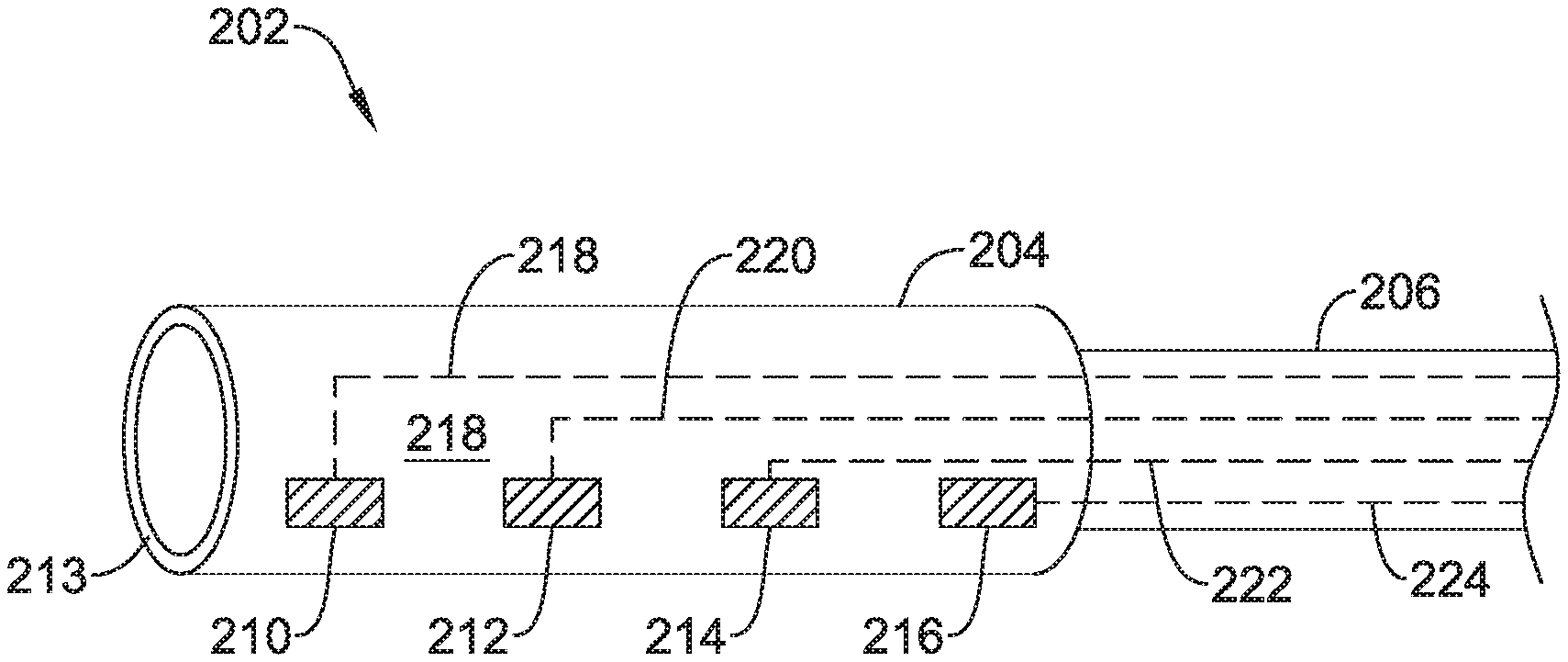
3. The delivery and deployment device of claim 1, wherein the plurality of electrodes comprise at least four electrodes spaced axially along the exterior surface of the device containment housing, the at least four electrodes including a first electrode, a second electrode, a third electrode and a fourth electrode; the first electrode and the fourth electrode spaced apart a first distance to form a stimulation dipole providing a potential difference; the second electrode and the third electrode spaced apart a second distance less than the first distance to provide a conductivity measurement by measuring a voltage between the second electrode and the third electrode resulting from the potential difference applied by the first electrode and the second electrode; and the second electrode and the third electrode disposed between the first electrode and the fourth electrode.
4. The delivery and deployment device of claim 1, wherein the plurality of electrodes comprise a first electrode and a second electrode disposed on an exterior surface of the device containment housing to form a stimulation bipole.
5. The delivery and deployment device of claim 4, further comprising a pressure sensor configured to obtain an indication of pressure in the chamber of the patient's heart in response to a stimulating electrical pulse delivered via the first electrode and the second electrode.
6. The delivery and deployment device of claim 5, wherein the pressure sensor is disposed at or near a proximal end of the device containment housing.
7. The delivery and deployment device of claim 4, further comprising: a first pressure sensor configured to obtain an indication of pressure in the chamber of the patient's heart; and a second pressure sensor configured to obtain an indication of pressure in a different chamber of the patient's heart.
8. The delivery and deployment device of claim 4, further comprising an accelerometer and/or a gyroscope operatively fixed to the device containment housing, the accelerometer and/or the gyroscope are configured to output a signal to the testing device representative of cardiac performance.
9. The delivery and deployment device of claim 1, wherein at least some of the plurality of electrodes are disposed on an expandable assembly movably secured about an exterior of the device containment housing, the expandable assembly movable to a deployed configuration in which at least some of the plurality of electrodes contact cardiac tissue for endocardial mapping of at least part of the chamber of the patient's heart prior to IMD deployment.
10. The delivery and deployment device of claim 1, further comprising one or more magnet tracking sensor fixed relative to the device containment housing for tracking purposes.
11. An IMD implantation device configured to deliver an implantable medical device (IMD) to a chamber of a patient's heart and deploy the IMD therein, the IMD implantation device comprising: a handle assembly; a shaft extending distally from the handle assembly, the shaft including a distal region; a device containment housing coupled to the distal region of the shaft and extending distally therefrom, the device containment housing configured to accommodate at least part of the IMD therein; a deployment member extending through the shaft, the deployment member configured to apply a deployment force to the IMD in order to move the IMD from the device containment housing to deploy the IMD in the patient's heart; a plurality of electrodes distributed about an exterior surface of the device containment housing such that at least some of the plurality of electrodes may be positioned to test a potential IMD deployment location defined by the device containment housing before deploying the IMD; and a plurality of electrical conductors operably coupled with the plurality of electrodes and extending proximally back along the shaft toward the handle assembly, the plurality of electrical conductors having proximal ends configured to be operably coupled to a testing device, wherein the testing device is configured to deliver electrical stimulation pulses to the at least some of the plurality of electrodes to test the potential IMD deployment location defined by the device containment housing before deploying the IMD.
12. The IMD implantation device of claim 11, wherein the deployment member is a push tube, and wherein the IMD implantation device further comprises: a tether extending distally through the push tube and coupled to the IMD, the tether configured to be used to retrieve the IMD back into the device containment housing if an alternate deployment location is desired.
13. The IMD implantation device of claim 12, wherein the plurality of electrodes comprise at least four electrodes spaced axially along the device containment housing, the at least four electrodes including a first electrode, a second electrode, a third electrode and a fourth electrode; the first electrode and the fourth electrode are spaced apart a first distance to form a stimulation dipole providing a potential difference, wherein the fourth electrode extends to a distal end of the device containment housing; the second electrode and the third electrode are spaced apart a second distance less than the first distance to provide a conductivity measurement by measuring a voltage between the second electrode and the third electrode resulting from the potential difference applied by the first electrode and the second electrode; and the second electrode and the third electrode disposed between the first electrode and the fourth electrode.
14. The IMD implantation device of claim 11, wherein the plurality of electrodes comprise a first electrode and a second electrode disposed on an exterior surface of the device containment housing to form a stimulation bipole.
15. The IMD implantation device of claim 14, further comprising a pressure sensor configured to obtain an indication of pressure in the chamber of the patient's heart in response to a stimulating electrical pulse delivered via the first electrode and the second electrode.
16. The IMD implantation device of claim 15, wherein the pressure sensor is disposed at or near a proximal end of the device containment housing.
17. The IMD implantation device of claim 14, further comprising an accelerometer and/or a gyroscope fixed relative to the device containment housing.
Description
TECHNICAL FIELD
The present disclosure pertains to medical devices, and methods for manufacturing and/or using medical devices. More particularly, the present disclosure pertains to leadless devices and methods, such as leadless cardiac pacing devices and methods, and delivery devices and methods for such leadless cardiac pacing devices.
BACKGROUND
A wide variety of medical devices have been developed for medical use, for example, cardiac use. Some of these devices include catheters, leads, pacemakers, and the like, and delivery devices and/or systems used for delivering such devices. These devices are manufactured by any one of a variety of different manufacturing methods and may be used according to any one of a variety of methods. Of the known medical devices, delivery systems, and methods, each has certain advantages and disadvantages. There is an ongoing need to provide alternative medical devices and delivery devices as well as alternative methods for manufacturing and using medical devices and delivery devices.
SUMMARY
This disclosure provides design, material, manufacturing method, and use alternatives for medical devices, including delivery devices.
An example delivery and deployment device that is configured to deliver an implantable medical device (IMD) to a chamber of a patient's heart and to deploy the IMD may include a handle assembly and a shaft extending distally from the handle assembly, the shaft including a distal region. A device containment housing may be coupled to the distal region of the shaft and may extend distally therefrom. The distal containment housing may be configured to accommodate at least a portion of the IMD therein. The IMD may, for example, be a leadless pacemaker, a lead, a neurostimulation device, a sensor or any other suitable IMD. A plurality of electrodes may be distributed about an exterior surface of the device containment housing such that at least some of the plurality of electrodes may be positioned to test a potential IMD deployment location before deploying the IMD. In some cases, a plurality of electrical conductors may be operably coupled with the plurality of electrodes and may extend proximally back along the shaft toward the handle assembly, the plurality of electrical conductors having proximal ends configured to be operably coupled to a testing device.
Alternatively or additionally to any of the embodiments above, the plurality of electrodes may include at least some electrodes that are radially disposed about the exterior surface of the device containment housing.
Alternatively or additionally to any of the embodiments above, the plurality of electrodes may include at least four electrodes spaced axially along the exterior surface of the device containment housing, the at least four electrodes including a first electrode, a second electrode, a third electrode and a fourth electrode. The first electrode and the fourth electrode may be spaced apart a first distance to form a stimulation dipole providing a potential difference. The second electrode and the third electrode may be spaced apart a second distance less than the first distance to provide a conductivity measurement by measuring a voltage between the second electrode and the third electrode resulting from the potential difference applied by the first electrode and the second electrode and the second electrode and the third electrode disposed between the first electrode and the fourth electrode.
Alternatively or additionally to any of the embodiments above, the plurality of electrodes may include a first electrode and a second electrode disposed on an exterior surface of the device containment housing to form a stimulation bipole.
Alternatively or additionally to any of the embodiments above, the delivery and deployment device may further include a pressure sensor configured to obtain an indication of pressure in the chamber of the patient's heart in response to a stimulating electrical pulse delivered via the first electrode and the second electrode.
Alternatively or additionally to any of the embodiments above, the pressure sensor may be disposed at or near a proximal end of the device containment housing.
Alternatively or additionally to any of the embodiments above, the delivery and deployment device may further include a first pressure sensor that is configured to obtain an indication of pressure in the chamber of the patient's heart and a second pressure sensor that is configured to obtain an indication of pressure in a different chamber of the patient's heart.
Alternatively or additionally to any of the embodiments above, the delivery and deployment device may further include an accelerometer and/or a gyroscope that is fixed relative to the device containment housing.
Alternatively or additionally to any of the embodiments above, at least some of the plurality of electrodes are disposed on an expandable assembly movably secured about an exterior of the device containment housing, the expandable assembly movable to a deployed configuration in which at least some of the plurality of electrodes contact cardiac tissue for endocardial mapping of at least part of the chamber of the patient's heart prior to IMD deployment.
Alternatively or additionally to any of the embodiments above, the delivery and deployment device further includes one or more magnet tracking sensor fixed relative to the device containment housing for tracking purposes.
An example IMD implantation device that is configured to deliver an implantable medical device (IMD) to a chamber of a patient's heart and to deploy the IMD therein may include a handle assembly and a shaft extending distally from the handle assembly, the shaft including a distal region. A device containment housing may be coupled to the distal region of the shaft and may extend distally therefrom. The distal containment housing may be configured to accommodate at least a portion of the IMD therein. A deployment member may extend through the shaft and may be configured to apply a deployment force to the IMD in order to move the IMD from the device containment housing to deploy the IMD in the patient's heart. A plurality of electrodes may be distributed about an exterior surface of the device containment housing such that at least some of the plurality of electrodes may be positioned to test a potential IMD deployment location before deploying the IMD. A plurality of electrical conductors may be operably coupled with the plurality of electrodes and may extend proximally back along the shaft toward the handle assembly, the plurality of electrical conductors having proximal ends configured to be operably coupled to a testing device.
Alternatively or additionally to any of the embodiments above, the deployment member may be a push tube, and the IMD implantation device may further include a tether that extends distally through the push tube and is coupled to the IMD, the tether configured to be used to retrieve the IMD back into the device containment housing if an alternate deployment location is desired.
Alternatively or additionally to any of the embodiments above, the plurality of electrodes may include at least four electrodes spaced axially along the device containment housing, the at least four electrodes including a first electrode, a second electrode, a third electrode and a fourth electrode. The first electrode and the fourth electrode may be spaced apart a first distance to form a stimulation dipole providing a potential difference, wherein the fourth electrode extends to a distal end of the device containment housing. The second electrode and the third electrode may be spaced apart a second distance less than the first distance to provide a conductivity measurement by measuring a voltage between the second electrode and the third electrode resulting from the potential difference applied by the first electrode and the second electrode and the second electrode and the third electrode may be disposed between the first electrode and the fourth electrode.
Alternatively or additionally to any of the embodiments above, the plurality of electrodes may include a first electrode and a second electrode that are disposed on an exterior surface of the device containment housing to form a stimulation bipole.
Alternatively or additionally to any of the embodiments above, the IMD implantation device may further include a pressure sensor that is configured to obtain an indication of pressure in the chamber of the patient's heart in response to a stimulating electrical pulse delivered via the first electrode and the second electrode.
Alternatively or additionally to any of the embodiments above, the pressure sensor may be disposed at or near a proximal end of the device containment housing.
Alternatively or additionally to any of the embodiments above, the IMD implantation device may further include an accelerometer and/or a gyroscope that is fixed relative to the device containment housing.
An example implantation device that is configured to deliver a leadless cardiac pacemaker (LCP) to a chamber of a patient's heart and to deploy the LCP therein may include a handle assembly and a shaft that extends distally from the handle assembly, the shaft including a distal region. A device containment housing may be coupled to the distal region of the shaft and may extend distally therefrom, the device containment housing configured to accommodate the LCP therein. A deployment member may extend through the shaft and may be configured to apply a deployment force to the LCP in order to move the LCP from a distal end of the device containment housing to deploy the LCP in the patient's heart. One or more tracking sensors may be fixed relative to the device containment housing to facilitate tracking of the device containment housing.
Alternatively or additionally to any of the embodiments above, the one or more tracking sensors may include a magnetic tracking sensor to facilitate magnet tracking of the device containment housing and/or an impedance tracking sensor to facilitate impedance tracking of the device containment housing.
Alternatively or additionally to any of the embodiments above, the implantation device may further include an LCP disposed within the device containment housing, and the LCP may include one or more LCP magnetic tracking sensors to facilitate magnet tracking of the LCP and/or one or more LCP impedance tracking sensors to facilitate impedance tracking of the LCP.
The above summary of some illustrative embodiments is not intended to describe each disclosed embodiment or every implementation of the present disclosure. The Figures, and Detailed Description, which follow, more particularly exemplify some of these embodiments.
BRIEF DESCRIPTION OF THE DRAWINGS
The disclosure may be more completely understood in consideration of the following detailed description in connection with the accompanying drawings, in which:
FIG. 1 is a plan view of an example leadless pacing device implanted within a heart;
FIG. 2 is a side view of an example implantable leadless cardiac pacing device;
FIG. 3 is a cross-sectional view of the implantable leadless cardiac pacing device of FIG. 2;
FIG. 4 is a plan view of an example delivery device for an implantable leadless cardiac pacing device;
FIG. 5 is a partial cross-sectional side view of the distal portion of the delivery device of FIG. 4;
FIG. 6 is a top view of the handle of the illustrative delivery device of FIG. 4;
FIG. 7 is a bottom view of the handle of the illustrative delivery device of FIG. 4;
FIG. 8 is a cross-section view of the handle of the illustrative delivery device of FIG. 4 taken at line 8-8 in FIG. 6;
FIG. 9 is a perspective view of the handle of the illustrative delivery device of FIG. 4 with portions removed;
FIGS. 10A-10E are schematic views illustrating the use of the illustrative delivery device to deploy an implantable leadless cardiac pacing device;
FIGS. 11A-11B are schematic views illustrating an example telescoping feature of the illustrative delivery device;
FIG. 12 is a schematic view of a distal portion of the illustrative delivery device, showing features of the device containment housing;
FIG. 13 is a schematic view of a distal portion of the illustrative delivery device, showing features of the device containment housing;
FIG. 14 is a schematic view of a distal portion of the illustrative delivery device, showing features of the device containment housing;
FIG. 15 is a schematic view of a distal portion of the illustrative delivery device, showing features of the device containment housing;
FIG. 16 is a schematic view of a distal portion of the illustrative delivery device, showing features of the device containment housing;
FIG. 17 is a schematic view of a distal portion of the illustrative delivery device, showing features of the device containment housing;
FIG. 18 is a schematic view of a distal portion of the illustrative delivery device, showing features of the device containment housing;
FIG. 19 is a schematic view of a distal portion of the illustrative delivery device, showing features of the device containment housing; and
FIG. 20 is a schematic view of an illustrative imaging system.
While the disclosure is amenable to various modifications and alternative forms, specifics thereof have been shown by way of example in the drawings and will be described in detail. It should be understood, however, that the intention is not to limit the disclosure to the particular embodiments described. On the contrary, the intention is to cover all modifications, equivalents, and alternatives falling within the spirit and scope of the disclosure.
DETAILED DESCRIPTION
For the following defined terms, these definitions shall be applied, unless a different definition is given in the claims or elsewhere in this specification.
All numeric values are herein assumed to be modified by the term "about," whether or not explicitly indicated. The term "about" generally refers to a range of numbers that one of skill in the art would consider equivalent to the recited value (i.e., having the same function or result). In many instances, the terms "about" may include numbers that are rounded to the nearest significant figure.
The recitation of numerical ranges by endpoints includes all numbers within that range (e.g. 1 to 5 includes 1, 1.5, 2, 2.75, 3, 3.80, 4, and 5).
As used in this specification and the appended claims, the singular forms "a", "an", and "the" include plural referents unless the content clearly dictates otherwise. As used in this specification and the appended claims, the term "or" is generally employed in its sense including "and/or" unless the content clearly dictates otherwise.
It is noted that references in the specification to "an embodiment", "some embodiments", "other embodiments", etc., indicate that the embodiment described may include one or more particular features, structures, and/or characteristics. However, such recitations do not necessarily mean that all embodiments include the particular features, structures, and/or characteristics. Additionally, when particular features, structures, and/or characteristics are described in connection with one embodiment, it should be understood that such features, structures, and/or characteristics may also be used connection with other embodiments whether or not explicitly described unless clearly stated to the contrary.
The following detailed description should be read with reference to the drawings in which similar structures in different drawings are numbered the same. The drawings, which are not necessarily to scale, depict illustrative embodiments and are not intended to limit the scope of the disclosure.
Cardiac pacemakers provide electrical stimulation to heart tissue to cause the heart to contract and thus pump blood through the vascular system. Conventional pacemakers may include an electrical lead that extends from a pulse generator implanted subcutaneously or sub-muscularly to an electrode positioned adjacent the inside or outside wall of the cardiac chamber. As an alternative to conventional pacemakers, self-contained or leadless cardiac pacemakers have been proposed. Leadless cardiac pacemakers are small capsules that may, for example, be fixed to an intracardiac implant site in a cardiac chamber. In some cases, the small capsule may include bipolar pacing/sensing electrodes, a power source (e.g. a battery), and associated electrical circuitry for controlling the pacing/sensing electrodes, and thus may provide electrical stimulation to heart tissue and/or sense a physiological condition. The capsule may be delivered to the heart using a delivery device which may be advanced through a femoral vein, into the inferior vena cava, into the right atrium, through the tricuspid valve, and into the right ventricle. Accordingly, it may be desirable to provide delivery devices which facilitate advancement through the vasculature.
FIG. 1 illustrates example implantable leadless cardiac pacing devices 10 (e.g., a leadless pacemaker) implanted in a heart H. An illustrative implantable medical device (IMD) 10 is shown within the right ventricle RV while another IMD 10 is shown within the left ventricle LV as the IMD 10 may be configured for implantation in either ventricle, or in another chamber such as a right atrium RA or a left atrium LA. Depending on therapeutic needs, a patient may have a single IMD 10 or may have two or more IMDs 10 implanted in appropriate chambers. A side view of the illustrative implantable medical device (IMD) 10 is shown in FIG. 2 and a cross-sectional view of the illustrative IMD 10, taken at line 3-3 in FIG. 2, is illustrated in FIG. 3. The implantable medical device 10 may include a shell or housing 12 having a proximal end 14 and a distal end 16. In some instances, the IMD 10 may include a first electrode 20 positioned adjacent to the distal end 16 of the housing 12 and a second electrode 22 positioned adjacent to the proximal end 14 of the housing 12. In some cases, the housing 12 may include a conductive material and may be insulated along at least a portion of its length. A section along the proximal end 14 may be free of insulation so as to define the second electrode 22. The electrodes 20, 22 may be sensing and/or pacing electrodes to provide electro-therapy and/or sensing capabilities. The first electrode 20 may be configured to be positioned against the cardiac tissue of the heart H or may otherwise contact the cardiac tissue of the heart H while the second electrode 22 may be spaced away from the first electrode 20, and thus spaced away from the cardiac tissue.
The IMD 10 may include a pulse generator (e.g., electrical circuitry) and a power source (e.g., a battery) within the housing 12 to provide electrical signals to the electrodes 20, 22 and thus control the pacing/sensing electrodes 20, 22. In some cases, electrical communication between the pulse generator and the electrodes 20, 22 may provide electrical stimulation to heart tissue and/or sense a physiological condition.
The IMD 10 may include a fixation mechanism 24 proximate the distal end 16 of the housing 12 configured to attach the IMD 10 to a tissue wall of the heart H, or otherwise anchor the IMD 10 to the anatomy of the patient. As shown in FIG. 1, in some instances, the fixation mechanism 24 may include one or more, or a plurality of hooks or tines 26 anchored into the cardiac tissue of the heart H to attach the IMD 10 to a tissue wall. In other cases, the fixation mechanism 24 may include one or more, or a plurality of passive tines, configured to entangle with trabeculae within the chamber of the heart H and/or a helical fixation anchor configured to be screwed into a tissue wall to anchor the IMD 10 to the heart H.
The IMD 10 may include a docking member 30 proximate the proximal end 14 of the housing 12 configured to facilitate delivery and/or retrieval of the IMD 10. For example, the docking member 30 may extend from the proximal end 14 of the housing 12 along a longitudinal axis of the housing 12. The docking member 30 may include a head portion 32 and a neck portion 34 extending between the housing 12 and the head portion 32. The head portion 32 may be an enlarged portion relative to the neck portion 34. For example, the head portion 32 may have a radial dimension from the longitudinal axis of the IMD 10 which is greater than a radial dimension of the neck portion 34 from the longitudinal axis of the IMD 10. The docking member 30 may further include a tether retention structure 36 extending from the head portion 32. The tether retention structure 36 may define an opening 38 configured to receive a tether or other anchoring mechanism therethrough. While the retention structure 36 is shown as having a generally "U-shaped" configuration, the retention structure 36 may take any shape which provides an enclosed perimeter surrounding the opening 38 such that a tether may be securably and releasably passed (e.g. looped) through the opening 38. The retention structure 36 may extend though the head portion 32, along the neck portion 34, and to or into the proximal end 14 of the housing 12, as is shown more clearly in FIG. 3. The docking member 30 may be configured to facilitate delivery of the IMD 10 to the intracardiac site and/or retrieval of the IMD 10 from the intracardiac site. Other docking members 30 are contemplated.
In some cases, the IMD 10 may include one or more sensors or other devices that facilitate tracking the IMD 10 during and/or after delivery. In some cases, as schematically illustrated, the IMD 10 may include a sensor 200 that is disposed on or within the IMD 10. In some cases, the sensor 200 may be considered to represent one or more magnetic tracking sensors that may facilitate magnetic tracking of the IMD 10 using a system such as will be described with respect to FIG. 20. An illustrative but non-limiting example of such a system is the RHTHYMIA.RTM. system available from Boston Scientific. In some cases, the sensor 200 may be considered to represent one or more impedance tracking sensors that may facilitate impedance tracking of the IMD 10. In some cases, the sensor 200 may be considered to represent one or more magnetic tracking sensors and one or more impedance tracking sensors, both of which may facilitate impedance tracking of the IMD 10.
In some cases, the IMD 10 may be delivered to the heart H using a delivery device which may be advanced through a femoral vein, into the inferior vena cava, into the right atrium, through the tricuspid valve, and into the right ventricle. Accordingly, it will be appreciated that the delivery device may need to be navigated through relatively tortuous anatomy to deliver the IMD 10 to a suitable location. The target region for the delivery of the IMD 10 may be a portion of the right ventricle, for example, a portion of the right ventricle near the apex of the heart. The target region may also include other regions of the heart (e.g., right atrium, left atrium, or left ventricle), blood vessels, or other suitable targets. It may be desirable to provide the delivery system with certain features that may allow for easier or better control for navigation or delivery purposes.
FIG. 4 is a plan view of an illustrative delivery device 100, such as a catheter, that may be used to deliver the IMD 10. It will be appreciated that the delivery device 100 is merely illustrative, as the IMD 10 may be delivered with other delivery devices that may or may not include some of the features described with respect to the delivery device 100. As illustrated, the delivery device 100 may include an outer tubular member 102 having a proximal section 104 and a distal section 106. An intermediate tubular member 110 may be longitudinally slidably disposed within a lumen 150 of the outer tubular member 102 (see e.g. FIG. 5). An inner tubular member 116 may be longitudinally slidably disposed within a lumen 152 of the intermediate tubular member 110 (see e.g. FIG. 5). A distal holding section, or device containment housing 108 may be attached to a distal end portion 114 of the intermediate tubular member 110, as illustrated in FIG. 5. The delivery device 100 may also include a handle assembly 120 positioned adjacent to the proximal section 104 of the outer tubular member 102. In some instances, the outer tubular member 102 may include at least a section thereof that has an outer diameter D2 that is less than the outer diameter D1 of at least a portion of the device containment housing 108 (see e.g. FIG. 5).
The handle assembly 120 may include a first or distal hub portion 126 attached to, such as fixedly attached to, the proximal end section 104 of the outer tubular member 102, a second or intermediate hub portion 128 attached to, such as fixedly attached to, a proximal end section of the intermediate tubular member 110, and a third or proximal hub portion 130 attached to, such as fixedly attached to, a proximal end section of the inner tubular member 116 (see e.g. FIG. 5). The first hub portion 126, second hub portion 128, and third hub portion 130 may be positioned in a generally telescoping arrangement and longitudinally slidable relative to each other. As will be discussed in more detail below, each of the first hub portion 126, the second hub portion 128, and the third hub portion 130 may be longitudinally slidable and rotatable relative to each other such that the outer tubular member 102, intermediate tubular member 110, and inner tubular member 116 may be individually actuated. In some instances, it may be desirable to move the outer tubular member 102, intermediate tubular member 110 and inner tubular member 116 simultaneously. The handle assembly 120 may include a multi-stage deployment mechanism or a first locking mechanism 134 to releasably couple the second hub portion 128 to the third hub portion 130 to prevent relative longitudinal movement therebetween, and thus prevent relative longitudinal movement between the intermediate tubular member 110 and the inner tubular member 116, as will be discussed in more detail below. The handle assembly 120 may also include a second locking mechanism 132 to releasably couple the first hub portion 126 to the second hub portion 128 to prevent relative longitudinal movement therebetween, and thus prevent relative longitudinal movement between the outer tubular member 102 and the intermediate tubular member 110, as will be discussed in more detail below.
The device containment housing 108 may be configured to receive the IMD 10 therein. For example, referring to FIG. 5, which illustrates a cross-sectional view of a distal portion of the delivery device 100, the device containment housing 108 may define a cavity 142 for slidably receiving the IMD 10, and may include a distal opening 144 for slidable insertion and/or extraction of the IMD 10 into and/or out of the cavity 142. The device containment housing 108 may include a body portion 138 and a distal tip portion 140 that may be, for example, configured to be atraumatic to anatomy, such as a bumper tip. For example, as the catheter is navigated through the anatomy, the distal tip may come into contact with anatomy. Additionally, when the catheter is used to deliver the implantable medical device 10, the tip 140 of the delivery device 100 will likely come into contact with tissue adjacent the target site (e.g. cardiac tissue of the heart).
In some cases, a hard distal tip formed of the material of the outer tubular member 102 and/or intermediate tubular member 110 may injure a vessel wall or cardiac tissue. As such, it may be desirable to provide the delivery device 100 with a softer distal tip 140 that can be introduced into the anatomy and come into contact with anatomy adjacent the target cite without causing unnecessary trauma. In some cases, the distal tip 140 may be made of a material that is softer than the body portion 138 of the device containment housing 108. In some cases, the distal tip 140 may include a material that has a durometer that is less than the durometer of the material of the body portion 138. In some particular embodiments, the durometer of the material used in the distal tip 140 may be in the range of about 5 D to about 70 D, or for example, in the range of about 25 D to about 65 D. Additionally, the distal tip 140 may include a shape or structure that may make it less traumatic to tissue. For example, the distal tip 140 may have a distal surface, such as a tissue contacting surface, that is that is rounded or includes a curvature configured to be more atraumatic to tissue.
In some instances, all or a portion of the device containment housing 108 may include an inner surface that may be configured to resist getting caught on the fixation mechanism 24, such as the one or more, or a plurality of hooks or tines 26 on the implantable medical device 10. For example, the device containment housing 108 may include an inner layer or coating of harder or more lubricious material that resists force applied by the fixation mechanism 24 onto the inner surface of the device containment housing 108. For example, the device containment housing 108 may include a multi-layered structure, and an inner layer may be made of a material that is harder than an outer layer.
The inner tubular member 116 may be disposed (e.g., slidably disposed) within a lumen 152 of the intermediate tubular member 110. The inner tubular member 116 may be engaged by a user near or at the third hub portion 130, and extend through a lumen 152 of the intermediate tubular member 110 and into the device containment housing 108. A distal portion 118 of the inner tubular member 116 may be capable of engaging the IMD 10, and the inner tubular member 116 may be used to "push" the IMD 10 out from device containment housing 108 so as to deploy and anchor the IMD 10 within a target region (e.g., a region of the heart such as the right ventricle). The inner tubular member 116 may have a lumen 154 extending from the proximal end 117 to a distal portion 118 thereof. A tether 112 or other retaining feature may be used to releasably secure the IMD 10 to the delivery device 100. In some instances, the tether 112 may be a single or unitary length of material that may extend from a proximal end 117 of the lumen 154, out through the distal portion 118, through the opening 38 of the IMD 10 and return to the proximal end 117 of the inner tubular member 116 through the lumen 154 such that both ends of the tether 112 are positioned adjacent to the third hub portion 130. In some instances, as will be discussed in more detail below, the ends of the tether 112 may be secured within a locking feature in the third hub portion 130.
In order to more specifically place or steer the delivery device 100 to a position adjacent to the intended target, the delivery device 100 may be configured to be deflectable or articulable or steerable. Referring to FIG. 4, for example, the outer tubular member 102 and/or intermediate tubular member 110 may include one or more articulation or deflection mechanism(s) that may allow for the delivery device 100, or portions thereof, to be deflected, articulated, steered and/or controlled in a desired manner. For example, the outer tubular member 102 may include at least a portion thereof that can be selectively bent and/or deflected in a desired or predetermined direction. This may, for example, allow a user to orient the delivery device 100 such that the device containment housing 108 is in a desirable position or orientation for navigation or delivery of the IMD 10 to a target location. The outer tubular member 102 may be deflected, for example, along a deflection region.
A wide variety of deflection mechanisms may be used. In some example embodiments, deflection may be effected by one or more actuation members, such as pull wire(s) extending between a distal portion of the outer tubular member 102 and an actuation mechanism 122 near the proximal end of the outer tubular member 102. As such, the one or more pull wires may extend both proximally and distally of the desired deflection or bending region or point. This allows a user to actuate (e.g., "pull") one or more of the pull wires to apply a compression and/or deflection force to at least a portion of the outer tubular member 102 and thereby deflect or bend the outer tubular member 102 in a desired manner. In addition, in some cases the one or more wires may be stiff enough so that they can also be used to provide a pushing and/or tensioning force on the outer tubular member 102, for example, to "push" or "straighten" the shaft into a desired position or orientation.
In some embodiments, the actuation member takes the form of a continuous wire that is looped through or otherwise coupled to a distal end region of the outer tubular member 102 so as to define a pair of wire sections. Other embodiments are contemplated, however, including embodiments where the actuation member includes one or a plurality of individual wires that are attached, for example, to a metal or metal alloy ring adjacent the distal end region of the outer tubular member 102.
The actuation mechanism 122 may include a desired mechanism that may allow for applying tension (i.e. pulling force), or compression (i.e. pushing force), or both, on the actuation member(s). In some embodiments, the actuation mechanism 122 may include an external rotatable member 124 connected to and rotatable about the longitudinal axis of the handle assembly 120. The rotatable member 124 may threadingly engage an internal member that is attached to the proximal end of the actuation member(s) or pull wires. When the external rotatable member 124 is rotated in a first rotational direction, the internal member translates in a first longitudinal direction, thereby applying tension to the pull wire(s), which applies compression force to the shaft, so as to deflect the outer tubular member 102 from an initial position to a deflected position. When the external rotatable member 124 is rotated in a second rotational direction, the internal member translates in a second longitudinal direction, thereby reducing and/or releasing the tension on the pull wire(s), and allowing the outer tubular member 102 to relax back toward the initial position. Additionally, in some cases, as mentioned above, where the one or more wires may be stiff enough, rotation of the rotatable member 124 in the second rotational direction such that the internal member translates in a second longitudinal direction may apply compression to the wire(s), such that the wire(s) may apply tension to the outer tubular member 102 and "push" the outer tubular member 102 back toward an initial position, and possibly into additional positions beyond the initial position.
The one or more articulation and/or deflection mechanism(s) may also entail the outer tubular member 102 including structure and/or material that may provide for the desired degree and/or location of the deflection when the compressive or tensile forces are applied. For example, the outer tubular member 102 may include one or more sections that include structure and/or material configured to allow the shaft to bend and/or deflect in a certain way when a certain predetermined compressive and/or tensile force is applied. For example, the shaft may include one or more sections that are more flexible than other sections, thereby defining a bending or articulating region or location. Some such regions may include a number of varying or changing flexibility characteristics that may define certain bending shapes when predetermined forces are applied. Such characteristics may be achieved through the selection of materials or structure for different sections of the outer tubular member 102.
In other embodiments, other articulation and/or deflection mechanism(s) are contemplated. For example, all or a portion of the delivery device 100, such as the outer tubular member 102, may be made of a shape memory material, such as a shape memory polymer and/or a shape memory metal. Such materials, when stimulated by an actuation mechanism, such as a change in temperature or the application of an electrical current, may change or move from a first shape to a second shape. As such, these material and mechanism may be used to deflect or bend the outer tubular member 102 in a desired manner. Other suitable deflection mechanism(s) that are able to deflect the delivery device 100 may also be used. Such alternative mechanisms may be applied to all other embodiments shown and/or discussed herein, and others, as appropriate.
Furthermore, the outer tubular member 102 may include one or more predefined or fixed curved portion(s) along the length thereof. In some cases, such curved sections may be configured to fit with particular anatomies or be configured for better navigation or delivery of the IMD 10. Additionally, or alternatively, some such curved sections may be configured to allow the outer tubular member 102 to be predisposed to be bent and/or deflected in a certain direction or configuration when compression and/or tension forces are applied thereto. In some cases, the outer tubular member 102 may be a laser cut metallic tubing, a braid reinforced polymeric tubing, or other flexible tubular structure as desired.
Returning again to FIG. 5, the device containment housing 108 may be affixed to a distal end portion 114 of the intermediate tubular member 110. The device containment housing 108 may include a hub portion 136 and a tubular body portion 138. In some instances, the hub portion 136 may be formed from a metal or metal alloy while the body portion 138 may be formed from a polymeric material, although this is not required. In some instances, a proximal region 143 of the body portion 138 may be heat bonded to a distal end portion 137 of the hub portion 136, or otherwise affixed. The hub portion 136 may include a tapered intermediate region 145 disposed between a proximal end portion 139 and the distal end portion 137.
In some cases, the outer tubular member 102 may include a metal ring or tip adjacent the distal end 103 thereof for attaching one or more pull wires thereto. In some cases, the outer tubular member 102 may further include a lubricious liner, such as, but not limited to a polytetrafluoroethylene (PTFE) liner. The proximal end portion 139 of the hub portion 136 may extend proximally into the lumen 150 of the outer tubular member 102. In some instances, an outer surface of the proximal end portion 139 may form an interference fit with an inner surface of the outer tubular member 102. In some cases, the outer surface of the proximal end portion 139 and the inner surface of the outer tubular member 102 may be coupled in a tapered engagement. For example, the distal end 103 of the outer tubular member 102 may flare radially outwards in the distal direction and/or the proximal end portion 139 may taper radially inward in the proximal direction. The two angled surfaces may engage as the proximal end portion 139 is proximally retracted within the outer tubular member 102. Other coupling arrangements may be used as desired.
In some cases, as the outer tubular member 102 is bent to navigate the IMD 10 to the desired location, the proximal end portion 139 may advance distally and disengage from the inner surface of the outer tubular member 102 creating a kink point or weakened region adjacent to the bonding region 146. Proximally retracting the intermediate tubular member 110 to bring the intermediate region 145 into contact with the outer tubular member 102 at contact point 148 and/or bringing the proximal end portion 139 into the outer tubular member 102 and fixing the intermediate tubular member 110 in this configuration may help prevent migration of the device containment housing 108 during navigation of the delivery device 100 to the desired location. Such a configuration may also place the intermediate tubular member 110 in tension while the device containment housing 108 applies a compression force on the outer tubular member 102, as will be discussed in more detail below. As discussed above, a locking mechanism 132 in the handle assembly 120 may be utilized to releasably maintain the outer tubular member 102 and the intermediate tubular member 110 in a desired orientation.
FIG. 6 illustrates a top view of the handle assembly 120 of the delivery device 100. FIG. 7 illustrates a bottom view of the handle assembly, approximately 180.degree. from the view shown in FIG. 6. The handle assembly 120 may include one or more ports 158, 160, 162 for delivering fluids, such as, but not limited to, a contrast and/or flushing fluid to the cavity 142 of the device containment housing 108. The flush ports 158, 160, 162 may be in fluid communication with the lumens 150, 152, 154 of the outer, intermediate or inner tubular members 102, 110, 116, as desired. For example, the flush port 158 may be in fluid communication with the lumen 150 of the outer tubular member 102, the flush port 160 may be in fluid communication with the lumen 152 of the intermediate tubular member 110, and the flush port 162 may be in fluid communication with the lumen 154 of the inner tubular member 116.
The handle assembly 120 may further include a tether lock 164. The tether lock 164 may be actuatable between a locked and an unlocked configuration to maintain the tether 112 in a desired orientation. The ends of the tether 112 may affixed to, secured to, or otherwise engage a tether cap 166 positioned at a proximal end of the third hub portion 130. The tether cap 166 may be removably secured to the third hub portion 130 to allow a clinician access to the ends of the tether 112. When the tether lock 164 is in the locked configuration, the tether cap 166 may not be removed from the third hub portion 130. When the tether lock 164 is in the unlocked configuration, the tether cap 166 may be removed and the ends of the tether 112 may be actuated. For example, once the IMD 10 has been implanted and its location verified, the tether 112 may be removed from the tether retention feature 36 of the IMD 10 by pulling on one of the ends until the opposite end has passed through the opening 38 such that the IMD 10 is free from the tether 112.
In some instances, the handle assembly 120 may also include visual markings, such as, but not limited to the markings illustrated at 170, 172, 174. These markings 170, 172, 174 may provide visual instructions or indications to the clinician. For example, the marking shown at 170 may be positioned proximate the rotatable member 124 of the actuation mechanism 122 to indicate that the rotatable member 124 controls deflection of the outer tubular member 102 and/or to indicate which direction the distal section 106 will deflect when the rotatable member 124 of the actuation mechanism 122 is rotated in a given direction. The markings shown at 172 may provide an indication of whether the second locking mechanism 132 is in the unlocked and/or locked configuration. Similarly, the markings shown at 174 may provide an indication of whether the tether lock 164 is in the unlocked and/or locked configuration.
FIG. 8 illustrates a cross-sectional view of the handle assembly 120 of the delivery device. As discussed above, the handle assembly 120 may include a first hub portion 126 attached to the proximal end section 104 of the outer tubular member 102, a second hub portion 128 attached to a proximal end section of the intermediate tubular member 110, and a third hub portion 130 attached to a proximal end section of the inner tubular member 116. Each of the first hub portion 126, the second hub portion 128, and the third hub portion 130 may be slidable and rotatable relative to each other such that the outer tubular member 102, intermediate tubular member 110, and inner tubular member 116 may be individually longitudinally actuated.
The inner tubular member 116 may extend distally from a proximal end 117. The proximal end 117 of the inner tubular member 116 may be positioned within or adjacent to the tether lock 164. The tether lock 164 may include a port 162 which may be in fluid communication with a lumen 154 of the inner tubular member 116. The lumen 154 may extend from the proximal end 117 to the distal portion 118 for delivering fluids, such as, but not limited to, a contrast and/or flushing fluid to the cavity 142 of the device containment housing 108. In some instances, the inner tubular member 116 may be coupled or affixed to the third hub portion 130 adjacent the proximal end 117 of the inner tubular member 116, although this is not required. In some cases, the inner tubular member 116 may be affixed to the third hub portion 130 at any longitudinal location desired. In some instances, a tether, such as tether 112, for securing the IMD 10 to the distal portion 118 of the inner tubular member 116 may be disposed within the lumen 154 and may exit the delivery device 100 through or adjacent to tether cap 166, although this is not required.
The intermediate tubular member 110 may extend distally from a proximal end 111. The proximal end 111 of the intermediate tubular member 110 may be positioned within the second hub portion 128. The intermediate tubular member 110 may include a lumen 152 extending from the proximal end 111 to a distal end of the intermediate tubular member 110. The inner tubular member 116 may be slidably disposed within the lumen 152 of the intermediate tubular member 110. In some instances, the intermediate tubular member 110 may be coupled or affixed to the second hub portion 128 adjacent the proximal end 111 of the intermediate tubular member 110, although this is not required. In some cases, the intermediate tubular member 110 may be affixed to the second hub portion 128 at any longitudinal location desired.
The outer tubular member 102 may extend distally from a proximal end 105. The proximal end 105 of the outer tubular member 102 may be positioned within the first hub portion 126. The outer tubular member 102 may include a lumen 150 extending from the proximal end 105 to a distal end 103 of the outer tubular member 102. The intermediate tubular member 110 may be longitudinally slidably disposed within the lumen 150 of the outer tubular member 102. In some instances, the outer tubular member 102 may be coupled or affixed to the first hub portion 126 adjacent the proximal end 105 of the outer tubular member 102, although this is not required. In some cases, the outer tubular member 102 may be affixed to the first hub portion 126 at any longitudinal location desired.
In some instances, the first hub portion 126 may include a retaining ring 182 positioned adjacent to a proximal end of the first hub portion 126. In some instances, the retaining ring 182 may be rotatable about a longitudinal axis of the handle assembly 120. In some cases, the retaining ring 182 may include locking features configured to engage with other locking features of the locking mechanism 132. When the retaining ring 182 engages other features of the locking mechanism 132, longitudinal movement of the first hub portion 126 and the second hub portion 128 relative to one another may be prevented. Rotating the retaining ring 182 may disengage the retaining ring 182 from the other features of the locking mechanism 132. This may allow for longitudinal movement of the first hub portion 126 and the second hub portion 128 relative to one another, as will be described in more detail below. While the second locking mechanism 132 is described as a rotating retaining ring 182, other locking mechanisms capable of releasably securing first hub portion 126 and the second hub portion 128, and thus the outer tubular member 102 and the intermediate tubular member 110, may be used.
In some instances, the first locking mechanism 134 may include a depressible button 131. The depressible button 131 may include a first outwardly protruding portion 133 configured to engage a region of the third hub portion 130 and a second inwardly protruding portion 135 configured to engage a region of the second hub portion 128. For example, the second protruding portion 135 may be disposed in and engage a groove or recess 178 formed in the second hub portion 128. The engagement of the first locking mechanism 134 may prevent or reduce relative movement of the second hub portion 128 and the third hub portion 130 when the first locking mechanism 134 is not actively actuated (e.g. depressed) by a clinician. A downward force 186 may be applied to the button 131. The force 186 may cause the first protruding portion 133 to lower and/or disengage from a surface of the third hub portion 130 and the second protruding portion 135 to raise and/or disengage from a surface of the second hub portion 128. This may allow the third hub portion 130 to be moved longitudinally (e.g., proximally and/or distally), as shown at 184, along a longitudinal axis of the handle assembly 120 relative to the second hub portion 128, as will be discussed in more detail below. Longitudinal actuation of the third hub portion 130 relative to the second hub portion 128 may result in a corresponding longitudinal actuation of the inner tubular member (and hence the IMD 10) relative to the intermediate tubular member 110 and the device containment housing 108. Such actuation may be used to incrementally deploy the IMD 10. FIG. 8 illustrates the second protruding portion 135 disposed in the middle of the recess 178. However, in some cases, during advancement of the delivery device 100 to the desired treatment location, the second protruding portion 135 may be positioned at the proximal end of the recess 178 to ensure the IMD 10 is fully disposed in the device containment housing 108. This is just an example. While the first locking mechanism 134 is described as a depressible button 131, in some cases other locking mechanisms capable of releasably securing the second hub portion 128 and the third hub portion 130, and thus the intermediate tubular member 110 and the inner tubular member 116, may be used.
FIG. 9 illustrates a partial perspective view of the handle assembly 120 with portions of the third hub portion 130 removed to more clearly illustrate features of the second hub portion 128. A proximal portion 127 of the second hub portion 128 may include a groove or recess 178 formed therein. The groove 178 may extend from a proximal end 179 to a distal end 181. In some embodiments, groove 178 may include a proximal portion 177 and a distal portion 183 which may be circumferentially offset from one another. A hard stop 180 may be provided at a region between the proximal end 179 and the distal end 181. The hard stop 180 may be a wall or other protrusion configured to engage the second protruding portion 135 of the first locking mechanism 134 such that in order to advance the second protruding portion 135 distally past the hard stop 180 from the proximal portion 177, the user rotates the third hub portion 130 to align the second protruding portion 135 with the distal portion 183 of the groove 178. This may allow the implantable medical device 10 to be incrementally deployed. During advancement of the delivery device 100 through the vasculature, the second protruding portion 135 may be disposed within the proximal portion 177 adjacent to the proximal end 179. As discussed above, the second protruding portion 135 may engage a surface of the second hub portion 128 to prevent and/or minimize relative movement of the second and third hub portions 128, 130 relative to one another.
The groove 178 may also include an angled region 198 between the proximal portion 177 and the distal portion 183 positioned generally opposite the hard stop 180. When the third hub portion 130 is proximally retracted from the distal end 181 to the proximal end 179, the angled region 198 may guide the second protruding portion 135 from the distal portion 183 of the groove 178 to the proximal portion 177 of the groove in a single fluid movement. For example, the third hub portion 130 may be proximally retracted from the distal end 181 to the proximal end 179 relative to the second hub portion 128 in a single proximal movement, if so desired, without prohibiting travel of the second protruding portion 135 from the distal portion 183 to the proximal portion 177.
A distal portion 129 of the second hub portion 128 may include a groove or recess 188 configured to receive a mating feature disposed on the first hub portion 126. This may allow the first hub portion 126 to be proximally retracted over the second hub portion 128, as will be discussed in more detail below. The proximal and distal portions 127, 129 of the second hub portion 128 may be separated by a gripping region 176 configured to provide a region for the clinician to hold.
Referring now to FIGS. 10A-10E, a method for deploying an IMD 10 using the illustrative delivery device 100 will now be described. For simplicity, these Figures show the IMDS 10 being delivered to the right ventricle RV. The delivery device 100 may be introduced into the vasculature through the femoral vein through a previously introduced guide catheter. This is just an example. It will be appreciated that the IMD 10 may be delivered and deployed in the left ventricle LV via an intra-aortic approach through the left atrium LA, for example. The delivery device 100 may be introduced through any desired location and with or without the use of a guide catheter as desired. The delivery device 100 may be advanced through the vasculature to the desired treatment location, which, in the case of a leadless cardiac pacing device, may be a chamber of the heart. The clinician may use the actuation mechanism 122 may to deflect the distal section 106 of the outer tubular member 102 in a desired manner to facilitate advancement of the delivery device 100. During advancement of the delivery device 100, the handle assembly 120 may be in a fully extended configuration, as shown in FIG. 10A. In such a configuration, the third hub portion 130 may be at its proximal-most location relative to the second hub portion 128 and the first hub portion 126 may be at its distal-most location relative to the second hub portion 128. When the handle assembly 120 is in its fully extending configuration, the inner tubular member 116, intermediate tubular member 110, and the outer tubular member 102 may be oriented in the manner illustrated in FIG. 5. The delivery device 100 can be imaged using known techniques to ensure accurate placement of the IMD 10.
Once the distal tip portion 140 of the device containment housing 108 has been positioned adjacent to the cardiac tissue where the IMD 10 is desired, deployment of the IMD 10 can begin. The first stage of deploying the IMD 10 may enable activation of the fixation mechanism 24. To initiate the first stage of deployment, the clinician may stabilize the first hub portion 126 relative to the patient and depress the button 131 of the first locking mechanism 134. The clinician may then slide the third hub portion 130 distally, as shown at 190, until the first locking mechanism 134 engages the hard stop 180 provided in the second hub portion 128 resulting in the handle assembly 120 configuration shown in FIG. 10B. Distal actuation of the third hub portion 130 may also move the inner tubular member 116 distally by the same distance. As the inner tubular member 116 advances distally, the distal portion 118 may "push" against the proximal end 14 of the implantable medical device 10. As the IMD 10 is pushed distally, the hooks 26 engage the heart tissue as shown in FIG. 10C. The IMD 10 may be distally advanced out of the device containment housing 108 to deploy the hooks or tines 26 from the device containment housing 108 to engage the hooks or tines 26 in the heart tissue while the proximal portion of the IMD 10 remains within the device containment housing 108. In some instances, the IMD 10 may be advanced distally in the range of 1 to 5 millimeters, although this is merely illustrative. This may allow the IMD 10 to be deployed while minimizing the amount of pressure applied to the heart wall. Further, the first locking mechanism 134 may prevent accidental or unintentional deployment of the IMD 10 as the button 131 must be actuated while advancing the third hub portion 130.
Referring briefly to FIGS. 11A and 11B, in some instances, it may be desirable to advance the device containment housing 108 and the intermediate tubular member 110 without advancing the outer tubular member 102 (i.e., telescoping the intermediate tubular member 110). For example, this may facilitate advancement of the delivery device 100 within the heart or maintain the position of the device containment housing 108 once it is placed again the heart wall. To distally advance or telescope the intermediate tubular member 110 relative to the outer tubular member 102, the second locking mechanism 132 may be actuated to "unlock" the first hub portion 126 and the second hub portion 128. As described above, a rotating retaining ring 182 may be rotated, as shown at 194, to move the second locking mechanism 132 from a locked to an unlocked configuration. Once the first locking mechanism has been unlocked, the clinician may distally advance 196 the second and third hub portions 128, 130 together to distally advance the device containment housing 108 as far as desired and/or needed. The actuation of the second and third hub portions 128, 130 may simultaneously move the intermediate tubular member 110 and the inner tubular member 116 as well. This may be done during advancement of the delivery device 100 through the vasculature, before initiating the first stage of deploying the IMD 10, and/or after the first stage of deploying the IMD 10 has been completed, as desired or needed.
After the first stage of deployment of the IMD 10, in which the tines or hooks 26 have been deployed from the device containment housing 108 into engagement with the heart wall, the tether 112 may be used to perform a tug test to determine if the IMD 10 is sufficiently engaged with the heart wall. In other words, the fixation of the IMD 10 (e.g. how well the hooks 26 are secured to the heart tissue) may be tested by gently tugging on the ends of the tether 112. If it is determined that the IMD 10 is sufficiently engaged with the heart wall, then the user may proceed to the second stage of deployment of the IMD 10 in which the remainder of the IMD 10 is expelled from the device containment housing 108. Otherwise, if the tug test fails and it is determined that the IMD 10 is not sufficiently engaged with the heart wall, the user may use the tether to pull (retract) the IMD 10, including the tines or hooks 26, back into the device containment housing 108 to release the implantable medical device 10 from the heart wall. The IMD 10 may then be repositioned and the first stage of deployment repeated.
Returning to FIG. 10B, the second stage of deploying the IMD 10 may proximally retract the device containment housing 108, and thus the intermediate tubular member 110, relative to the inner tubular member 116 to fully deploy the IMD 10. Once the clinician has determined that the position of the IMD 10 is satisfactory and the fixation mechanism 24 is securely engaged with the heart tissue, the intermediate tubular member 110, including the device containment housing 108, of the delivery device 100 can be proximally retracted. To initiate the second stage of the deployment, the clinician may first rotate the third hub portion 130, as shown at 192, such that the button 131 is aligned with the distal portion 183 of the groove 178. The clinician may then stabilize the third hub portion 130 relative to the patient and proximally retract the first and second hub portions 126, 128. It should be noted that while it is possible to distally actuate the third hub portion 130 at this point, this may cause additional and unnecessary forces to be applied to the heart wall. Further, such distal movement of the third hub portion 130 may move the inner tubular member 116 (and hence the implantable medical device 10) distally rather than proximally retracting the intermediate tubular member 110 and/or the outer tubular member 102. The first and second hub portions 126, 128 may be proximally retracted until the first locking mechanism 134 engages the distal end 181 of the groove 178, resulting in the handle assembly 120 configuration shown in FIG. 10D. Such actuation of the first and second hub portions 126, 128 may fully deploy the implantable medical device 10 such that the IMD 10 is exterior of the device containment housing 108 and engaged with the heart wall, as shown in FIG. 10E.
As can be seen in FIG. 10E, the IMD 10 may still be affixed to the delivery device 100 through the tether 112. Once the clinician has verified the position of the IMD 10, the fixation of the IMD 10 and/or the electrical performance of the IMD 10, the tether 112 may be removed. In some instances, fixation of the IMD 10 (e.g. how well the hooks 26 are secured to the heart tissue) may be tested by gently tugging on the ends of the tether 112. The tether 112 may be removed by unlocking the tether lock 164, removing the tether cap 166, cutting the tether 112 at some location along its length, and pulling on one of the ends until the opposite end has passed through the opening 38 of the IMD 10 such that the IMD 10 is free from the tether 112. In some instances, the tether 112 may be affixed to a portion of the tether cap 166 (e.g. creating a loop) such that the tether 112 must be cut to allow the IMD 10 to be freed from the tether 112.
In some cases, there may be a desire to test a possible implantation site before deploying and fixating the IMD 10. In some cases, a delivery device such as the delivery device 100 may include structure or otherwise be configured to be able to electrically test a possible implantation site by delivering an electrical pulse to cardiac tissue proximate the possible implantation site and measuring a resultant cardiac parameter. If the measured cardiac parameter indicates a good implantation site, the IMD 10 may be deployed and fixated at that implantation site as discussed with respect to FIGS. 10A-10E. Otherwise, the delivery device 100 may be moved to another possible site, which can then be tested. This may be repeated until an acceptable site is found. FIGS. 12-19 provide illustrative but non-limiting examples of how the delivery device 100 in general, and the device containment housing 108 in particular, may be modified to help in testing possible implantation sites.
FIG. 12 is a schematic diagram of a portion of an illustrative delivery device 202, which may be considered as being an example of the delivery device 100. In some cases, as illustrated, the delivery device 202 includes a device containment housing 204 extending distally from a shaft 206. In some cases, the device containment housing 204 may be considered as being an example of the device containment housing 108 while the shaft 206 may be considered as generally representing at least a portion of the intermediate tubular member 110 and the outer tubular member 102, and may in some cases be considered as extending proximally to the handle assembly 120. In some cases, as seen, the device containment housing 204 includes several electrodes that may be used in electrically testing a possible implantation site. The electrodes may, for example, be disposed on an outer surface 208 of the device containment housing 204 and in some cases may be axially and/or radially spaced apart on the outer surface 208. As shown, there is a first electrode 210, a second electrode 212, a third electrode 214 and a fourth electrode 216. In some cases, one or more of the electrodes 210, 212, 214 and 216 may extend radially at least partially about the outer surface 208.
In some cases, a first electrical connector 218 extends proximally from the first electrode 210, a second electrical connector 220 extends proximally from the second electrode 212, a third electrical connector 222 extends proximally from the third electrode 214 and a fourth electrical connector 224 extends proximally from the fourth electrode 216. In some cases, the electrical connectors 218, 220, 222 and 224 extend to the handle assembly 120 and enable a device such as but not limited to a programmer or tester to be electrically coupled to the electrodes 210, 212, 214 and 216 via the electrical connectors 218, 220, 222 and 224.
In some cases, the first electrode 210 and the fourth electrode 216 may, in combination, be considered as forming a stimulation bipole. A potential difference may be applied between the first electrode 210 and the fourth electrode 216, thereby creating a voltage therebetween. In some cases, the second electrode 212 and the third electrode 214 may be used to provide a resistance measurement by detecting a voltage between the second electrode 212 and the third electrode 214 resulting from the potential difference applied between the first electrode 210 and the fourth electrode 216. In some cases, as illustrated, the second electrode 212 and the third electrode 214 may be disposed between the first electrode 210 and the fourth electrode 216. It will be appreciated that in some cases, there may be a relationship between the detected resistance between the second electrode 212 and the third electrode 214 and the current chamber volume of the corresponding chamber of the heart when a current is applied between the first electrode 210 and the fourth electrode 216. In some cases, it may be possible, for example, to use the first electrode 210 and the third electrode 214 to stimulate and to use the second electrode 212 and the fourth electrode 216 to measure conductivity, for example. In some cases, an external electrode such as a temporary patch electrode may be worn by the patient and may for example be used as part of a stimulation circuit.
In some cases, the first electrode 210 may be smaller than the fourth electrode 216. When so provided, the first electrode 210 may be the cathode and the fourth electrode 216 may be the anode of the stimulation bipole (cathodic stimulation). While not explicitly shown, in some cases the first electrode 210 may extend over the distal end 213 of the device containment housing 204 so as to directly engage tissue when the distal end 213 of the device containment housing 204 is pushed up against a heart wall.
In some cases, conductivity values obtained via electrodes on the device containment housing 204 may, for example, be used to determine heart wall contact. For example, blood has a lower conductivity compared to tissue such as cardiac tissue. A relatively lower conductivity value may indicate a lack of tissue contact while a relatively higher conductivity value may indicate tissue contact, for example. In some cases, tissue composition may impact conductivity. For example, infarcted tissue has more collagen than healthy myocardium, and thus a conductivity value may be useful in determining whether a possible implantation site includes healthy myocardium or unhealthy myocardium, which can be important in achieving lower pacing threshold values.
FIG. 13 is a schematic diagram of a portion of an illustrative delivery device 226, which may be considered as being an example of the delivery device 100. In some cases, as illustrated, the delivery device 226 includes a device containment housing 228 extending distally from a shaft 230. In some cases, the device containment housing 228 may be considered as being an example of the device containment housing 108 while the shaft 230 may be considered as generally representing at least a portion of the intermediate tubular member 110 and the outer tubular member 102, and may in some cases be considered as extending proximally to the handle assembly 120. In some cases, as seen, the device containment housing 228 includes several electrodes that may be used in electrically testing a possible implantation site. The electrodes may, for example, be disposed on an outer surface 232 of the device containment housing 228 and in some cases may be axially and/or radially spaced apart on the outer surface 232. As shown, there is a first electrode 234 and a second electrode 236 that may function together as a stimulation bipole. While not explicitly shown, in some cases the first electrode 234 may extend over the distal end 235 of the device containment housing 228 so as to directly engage tissue when the distal end 235 of the device containment housing 228 is pushed up against a heart wall. In some cases, a first electrical connector 238 extends proximally from the first electrode 234 and a second electrical connector 240 extends proximally from the second electrode 212. In some cases, the electrical connectors 238 and 240 extend to the handle assembly 120 and enable a device such as but not limited to a programmer or tester to be electrically coupled to the electrodes 234 and 236 via the electrical connectors 238 and 240.
In some cases, a sensor 242 may be disposed on the shaft 230, near to the device containment housing 228. An electrical connector 244 may extend proximally from the sensor 242 and may extend to the handle assembly 120 and thus may be operably coupled with a programmer, tester or other device. In some cases, for example, the sensor 242 may be a pressure sensor such as a piezoelectric pressure sensor and may be configured to provide a signal representative of blood pressure within a cardiac chamber that results from a stimulation pulse applied as a potential difference between the first electrode 234 and the second electrode 236, for example. In some cases, the sensor 242 may instead represent an accelerometer or an acoustic sensor that can output a signal representative of cardiac performance in response to an applied stimulation pulse (e.g. heart sounds, heart wall acceleration, etc.). In some cases, the sensor 242 may represent a gyroscope that can output a signal representative of cardiac performance (e.g. twist) in response to an applied stimulation pulse. In some cases, the sensor 242 may include electronic components to amplify, filter or otherwise condition a raw sensor signal. In some cases, the sensor 242 may be a bidirectional transducer (e.g. a bidirectional acoustic transducer to facilitate ultrasound measurements).
In some cases, rather than using electrodes on the device containment housing 228 for stimulation, one or more electrodes on the IMD 10 may instead be used to stimulate cardiac tissue (provide a pacing pulse), and the electrodes 234 and 236 may instead be used to provide a resulting conductivity value. In some cases, the IMD 10 may be used to stimulate cardiac tissue and a sensor such as the sensor 242 may be used to measure a resulting cardiac parameter. In some cases, the device containment housing 228 may not include any electrodes.
In some cases, a delivery device may include two pressure sensors. As shown for example in FIG. 14, a delivery device 250 may include a device containment housing 252 extending proximally from shaft 254, and may be considered as being an example of the delivery device 100. In some cases, the device containment housing 252 may be considered as being an example of the device containment housing 108 while the shaft 254 may be considered as generally representing at least a portion of the intermediate tubular member 110 and the outer tubular member 102, and may in some cases be considered as extending proximally to the handle assembly 120. In some cases, as seen, the device containment housing 252 has an outer surface 256 and includes the first electrode 234 and the second electrode 236. In some cases, the first electrical connector 238 extends proximally from the first electrode 234 and the second electrical connector 240 extends proximally from the second electrode 212.
In some cases, a sensor 242 may represent a first pressure sensor and a sensor 258 may represent a second pressure sensor. The sensor 242 is shown operably coupled to the electrical connector 244 while the sensor 258 is shown operably coupled to an electrical connector 260 that extends proximally from the sensor 258 and thus may be operably coupled with a programmer, tester or other device. In some cases, for example, the sensor 242 and the sensor 258 may each be piezoelectric pressure sensors, or other types of pressure sensors, and may each be configured to provide a signal representative of blood pressure within a cardiac chamber that results from a stimulation pulse applied as a potential difference between the first electrode 234 and the second electrode 236, for example. In some cases, it will be appreciated that depending on the exact position of the delivery device 250 with respect to the patient's heart, the sensor 242 and the sensor 258 may see different pressure waveforms that may be useful in determining the appropriateness of a particular possible implantation site. For example, in some cases, the sensor 242 may see an atrial pressure waveform while the sensor 258 may see a ventricular pressure waveform. These may be useful in determining an A-V delay, for example.
FIGS. 15 and 16 provide illustrative but non-limiting examples of electrode configurations that may, for example, be considered as showing possible electrode configurations useable with any of the device containment housings 204 (FIG. 12), 228 (FIG. 13) and 252 (FIG. 14). FIG. 15 shows a device containment housing 270 that has an outer surface 272. A first ring electrode 274 and a second ring electrode 276 can be seen to be disposed on the outer surface 272. It will be appreciated that by having electrodes that extend at least partially, if not entirely, around the outer surface 272, there may be fewer issues with making tissue/blood contact regardless of rotational orientation of the device containment housing 204. While not explicitly shown, in some cases the first ring electrode 274 may extend over the distal end 273 of the device containment housing 270 so as to directly engage tissue when the distal end 273 of the device containment housing 270 is pushed up against a heart wall. While two electrodes 274, 276 are shown, it will be appreciated that the device containment housing 204 may include three, four or more electrodes. In some cases, the device containment housing 204 may also include one or more sensors that are configured to provide a signal representative of cardiac performance.
FIG. 16 shows a device containment housing 280 that has an outer surface 282. A first electrode constellation 284 and a second electrode constellation 286 can be seen to be disposed on the outer surface 282. In some cases, as illustrated, the first electrode constellation 284 includes an electrode 284a, an electrode 284b and an electrode 284c. The first electrode constellation 284 may include additional electrodes not visible in this view. Similarly, the second electrode constellation 286 may include an electrode 286a, an electrode 286b and an electrode 286c. The second electrode constellation 286 may include additional electrodes not visible in this view. In some cases, each of the electrodes 284a, 284b, 284c may be electrically coupled together. In some instances, each of the electrodes 284a, 284b, 284c may be individually addressable. While not explicitly shown, in some cases each of the electrodes 284a, 284b, 284c may extend over the distal end 283 of the device containment housing 280 so as to directly engage tissue when the distal end 283 of the device containment housing 280 is pushed up against a heart wall. In some cases, each of the electrodes 286a, 286b, 286c may be electrically coupled together. In some instances, each of the electrodes 286a, 286b, 286c may be individually addressable.
It will be appreciated that by having electrodes that extend at least partially, if not entirely, around the outer surface 282, there may be fewer issues with making tissue/blood contact regardless of rotational orientation of the device containment housing 280 relative to the heart H. While two electrode constellations 284, 286 are shown, it will be appreciated that the device containment housing 280 may include three, four or more electrode constellations. In some cases, the device containment housing 280 may also include one or more sensors that are configured to provide a signal representative of cardiac performance.
FIG. 17 is a schematic illustration of a device containment housing 290 including features that may be combined with any of the device containment housings 204 (FIG. 12), 228 (FIG. 13) and 252 (FIG. 14). The illustrative device containment housing 290 includes an outer surface 292 that extends from a distal end 294 to a proximal end 296. In some cases, the device containment housing 290 may include a vision system that enables a physician or other user to actually visualize a possible implantation site. A vision system may, for example, utilize intracardiac ultrasound, infrared imaging, direction vision, and the like. The distal end 294 includes a first visualization element 298 and a second visualization element 300. One these elements may, for example, be or otherwise include a light source while the other element includes a camera, or a fiber optic cable and a lens operably coupled to a proximally located camera for visualization.
FIGS. 18 and 19 are schematic illustrations of a portion of a delivery device 302, which may be considered as being an example of the delivery device 100, with FIG. 18 showing the delivery device 302 in a delivery configuration while FIG. 19 shows the delivery device 302 in a mapping configuration. In some cases, as illustrated, the delivery device 302 may include a device containment housing 304 extending distally from a shaft 306. In some cases, the device containment housing 304 may be considered as being an example of the device containment housing 108 while the shaft 306 may be considered as generally representing at least a portion of the intermediate tubular member 110 and the outer tubular member 102, and may in some cases be considered as extending proximally to the handle assembly 120. In some cases, as seen, the device containment housing 304 includes electrodes that may be used in electrically testing a possible implantation site.
In some cases, the device containment housing 304 includes an electrode assembly 310 that includes a distal ring 312 and a proximal ring 314, with a plurality of electrode supports 316 extending between the distal ring 312 and the proximal ring 314. Each of the plurality of electrode supports 316 include a plurality of individually addressable electrodes 318. In some cases, the distal ring 312 is secured relative to the device containment housing 304 while the proximal ring 314 may be slidable relative to the device containment housing 304. In some cases, a deployment member 320 may be operably coupled to the proximal ring 314 and extend proximally through the shaft 306 such that the proximal ring 314 may be moved forwards and backwards by pushing and pulling on the deployment member 320. In other cases, the distal ring 312 may be slidable, and the deployment member 320 may instead be operably coupled to the distal ring 312. In either case, in the deployed state, stimulation pulses (e.g. pacing pulses) may be sequentially applied to each of the plurality of individually addressable electrodes 318, and a response may be sensed and recorded. This may help determine a suitable implantation site for the IMD. Once a suitable implantation site has been determined, the deployment member 320 may be moved to retract the electrode supports 316, and the device containment housing 304 may be positioned over the suitable site and the IMD in the device containment housing 304 may be deployed and implanted at the site.
It will be appreciated that the electrode assembly 310 permits mapping of the endocardial surface. In some cases, this may be useful in determining or otherwise identifying intrinsic activation patterns. In some cases, mapping the endocardial surface may facilitate identification of scar tissue and possibly other damaged tissue, to be avoided when deploying the IMD 10. It will be appreciated that while no sensors are shown as being part of the delivery device 302, one or more sensors such as pressure sensors, accelerometers and/or gyroscopes may be included as part of the delivery device 302 in order to gauge cardiac response to an applied stimulation via each of two or more of the individually addressable electrodes 318, for example.
As noted with respect to FIG. 2, in some cases the IMD 10 may include one or more magnetic tracking sensors and/or impedance tracking sensors. FIG. 20 schematically illustrates a system 400 in which a patient P, including a heart H, is placed in front of (or on top of) a magnetic field generator 402. In some cases, a device disposed within the heart H includes a magnetic tracking sensor and/or an impedance tracking sensor 404. In some cases, when the magnetic field generator 402 is generating a magnetic field, and the magnetic tracking sensor 404 within the device is turned on, the magnetic tracking sensor 404 is able to determine its location relative to the magnetic field lines, and to communicate this information for display on a monitor 406. When a current generator (not shown) provides current to the body (e.g. via two or more electrode patches), an impedance tracking sensor within the device may be able to determine its location relative to the electric field lines, and to communicate this information for display on a monitor 406. In some cases, both magnetic tracking and impedance tracking may be used to identify and track the location of the device. In some cases, the device including the magnetic tracking sensor and/or an impedance tracking sensor 404 may be a leadless cardiac pacemaker (LCP) or other intracardially implanted device, and the system 400 may provide an indication of the location of the device within the body. In some cases, the device including the magnetic tracking sensor and/or impedance tracking sensor 404 may instead be a delivery device, and the magnetic tracking sensor and/or an impedance tracking sensor 404 may provide an indication of the location of the delivery device. In some cases, the magnetic tracking sensor and/or impedance tracking sensor 404 may not only provide location (X, Y, Z), but may also provide pitch, yaw, velocity, acceleration, twist, and/or other parameters related to the device's position.
As illustrated, the system 400 may be a structure that the patient P lies on, or perhaps stands in front of. In some cases, it is contemplated that the magnetic field generator 402 may be incorporated into a wearable vest that may be used for ambulatory measurements. In some cases, information provided by the system 400 may be used to help guide initial implantation and to verify fixation of the device (such as the IMD 10). In some cases, the data provided may be used for determining rate response sensor calibration, as otherwise heart motion can interfere with detecting physical movement of the patient. In some cases, a co-implanted device such as but not limited to a subcutaneous implantable cardioverter-defibrillator (SICD) may be used to generate the magnetic field and/or electric field (e.g. current). In some cases, the SICD may inject a current, which may be detected by the IMD 10 and this information may be used to improve location detection via impedance tracking.
The delivery device 100, 202, 226, 250, 302, or components thereof, may be made from a metal, metal alloy, polymer (some examples of which are disclosed below), a metal-polymer composite, ceramics, combinations thereof, and the like, or other suitable material. Some examples of suitable polymers may include polytetrafluoroethylene (PTFE), ethylene tetrafluoroethylene (ETFE), fluorinated ethylene propylene (FEP), polyoxymethylene (POM, for example, DELRIN.RTM. available from DuPont), polyether block ester, polyurethane (for example, Polyurethane 85A), polypropylene (PP), polyvinylchloride (PVC), polyether-ester (for example, ARNITEL.RTM. available from DSM Engineering Plastics), ether or ester based copolymers (for example, butylene/poly(alkylene ether) phthalate and/or other polyester elastomers such as HYTREL.RTM. available from DuPont), polyamide (for example, DURETHAN.RTM. available from Bayer or CRISTAMID.RTM. available from Elf Atochem), elastomeric polyamides, block polyamide/ethers, polyether block amide (PEBA, for example available under the trade name PEBAX.RTM.), ethylene vinyl acetate copolymers (EVA), silicones, polyethylene (PE), Marlex high-density polyethylene, Marlex low-density polyethylene, linear low density polyethylene (for example REXELL.RTM.), polyester, polybutylene terephthalate (PBT), polyethylene terephthalate (PET), polytrimethylene terephthalate, polyethylene naphthalate (PEN), polyetheretherketone (PEEK), polyimide (PI), polyetherimide (PEI), polyphenylene sulfide (PPS), polyphenylene oxide (PPO), poly paraphenylene terephthalamide (for example, KEVLAR.RTM.), polysulfone, nylon, nylon-12 (such as GRILAMID.RTM. available from EMS American Grilon), perfluoro(propyl vinyl ether) (PFA), ethylene vinyl alcohol, polyolefin, polystyrene, epoxy, polyvinylidene chloride (PVdC), poly(styrene-b-isobutylene-b-styrene) (for example, SIBS and/or SIBS 50A), polycarbonates, ionomers, biocompatible polymers, other suitable materials, or mixtures, combinations, copolymers thereof, polymer/metal composites, and the like. In some embodiments the polymer can be blended with a liquid crystal polymer (LCP). For example, the mixture can contain up to about 6 percent LCP.
Some examples of suitable metals and metal alloys include stainless steel, such as 304V, 304L, and 316LV stainless steel; mild steel; nickel-titanium alloy such as linear-elastic and/or super-elastic nitinol; other nickel alloys such as nickel-chromium-molybdenum alloys (e.g., UNS: N06625 such as INCONEL.RTM. 625, UNS: N06022 such as HASTELLOY.RTM. C-22.RTM., UNS: N10276 such as HASTELLOY.RTM. C276.RTM., other HASTELLOY.RTM. alloys, and the like), nickel-copper alloys (e.g., UNS: N04400 such as MONEL.RTM. 400, NICKELVAC.RTM. 400, NICORROS.RTM. 400, and the like), nickel-cobalt-chromium-molybdenum alloys (e.g., UNS: R30035 such as MP35-N.RTM. and the like), nickel-molybdenum alloys (e.g., UNS: N10665 such as HASTELLOY.RTM. ALLOY B2.RTM.), other nickel-chromium alloys, other nickel-molybdenum alloys, other nickel-cobalt alloys, other nickel-iron alloys, other nickel-copper alloys, other nickel-tungsten or tungsten alloys, and the like; cobalt-chromium alloys; cobalt-chromium-molybdenum alloys (e.g., UNS: R30003 such as ELGILOY.RTM., PHYNOX.RTM., and the like); platinum enriched stainless steel; titanium; combinations thereof; and the like; or any other suitable material.
In at least some embodiments, portions or all of the delivery device 100, 202, 226, 250, 302, or components thereof, may be doped with, made of, or otherwise include a radiopaque material. Radiopaque materials are understood to be materials capable of producing a relatively bright image on a fluoroscopy screen or another imaging technique during a medical procedure. This relatively bright image aids the user of the delivery device 100, 202, 226, 250, 302 in determining its location. Some examples of radiopaque materials can include, but are not limited to, gold, platinum, palladium, tantalum, tungsten alloy, polymer material loaded with a radiopaque filler, and the like. Additionally, other radiopaque marker bands and/or coils may also be incorporated into the design of the delivery device 100, 202, 226, 250, 302, or components thereof, to achieve the same result.
It should be understood that this disclosure is, in many respects, only illustrative. Changes may be made in details, particularly in matters of shape, size, and arrangement of steps without exceeding the scope of the disclosure. This may include, to the extent that it is appropriate, the use of any of the features of one example embodiment being used in other embodiments. The disclosure's scope is, of course, defined in the language in which the appended claims are expressed.
* * * * *
D00000
D00001
D00002
D00003
D00004
D00005
D00006
D00007
D00008
D00009
D00010
D00011
D00012
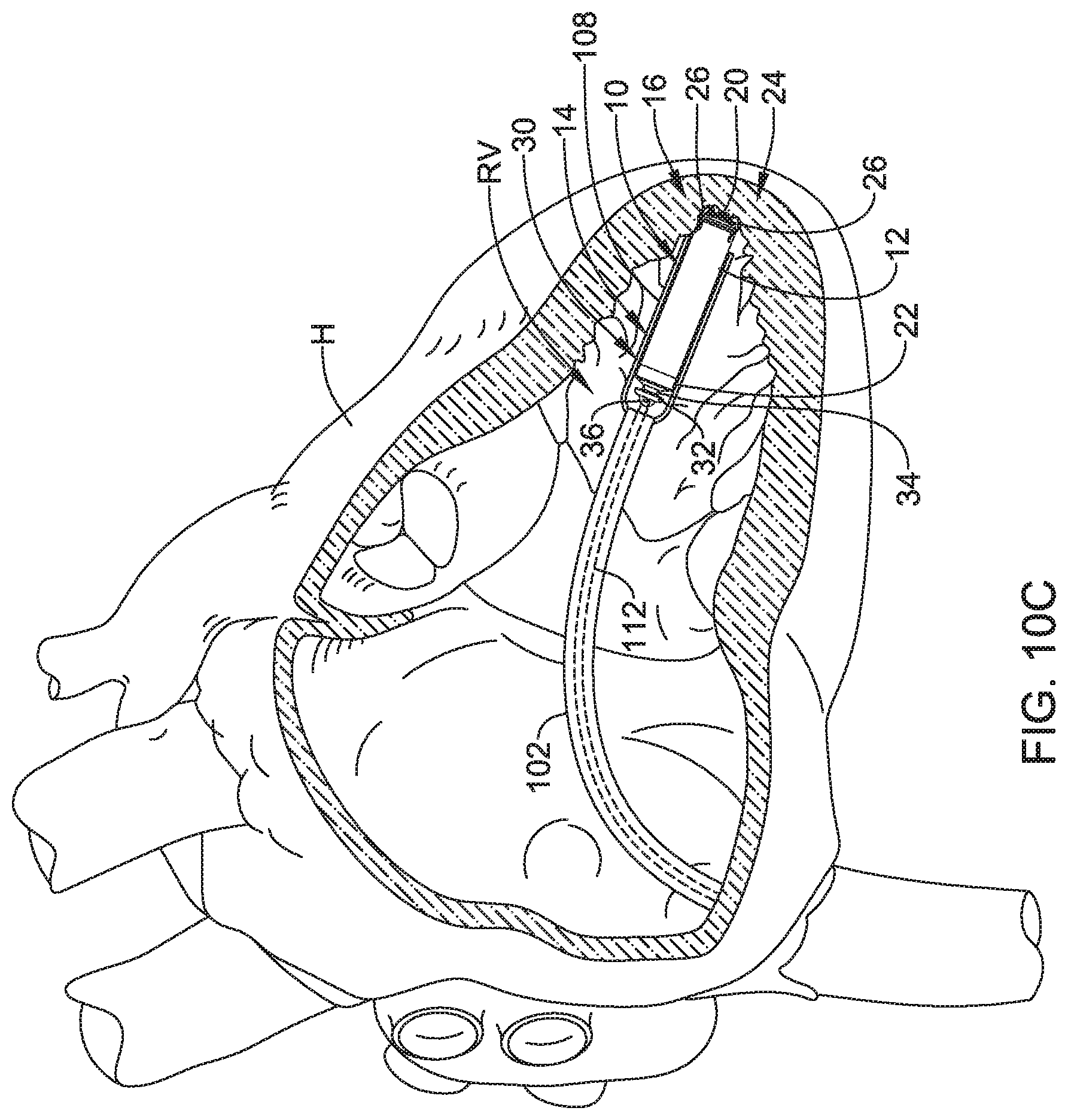
D00013

D00014

D00015

D00016

D00017

D00018
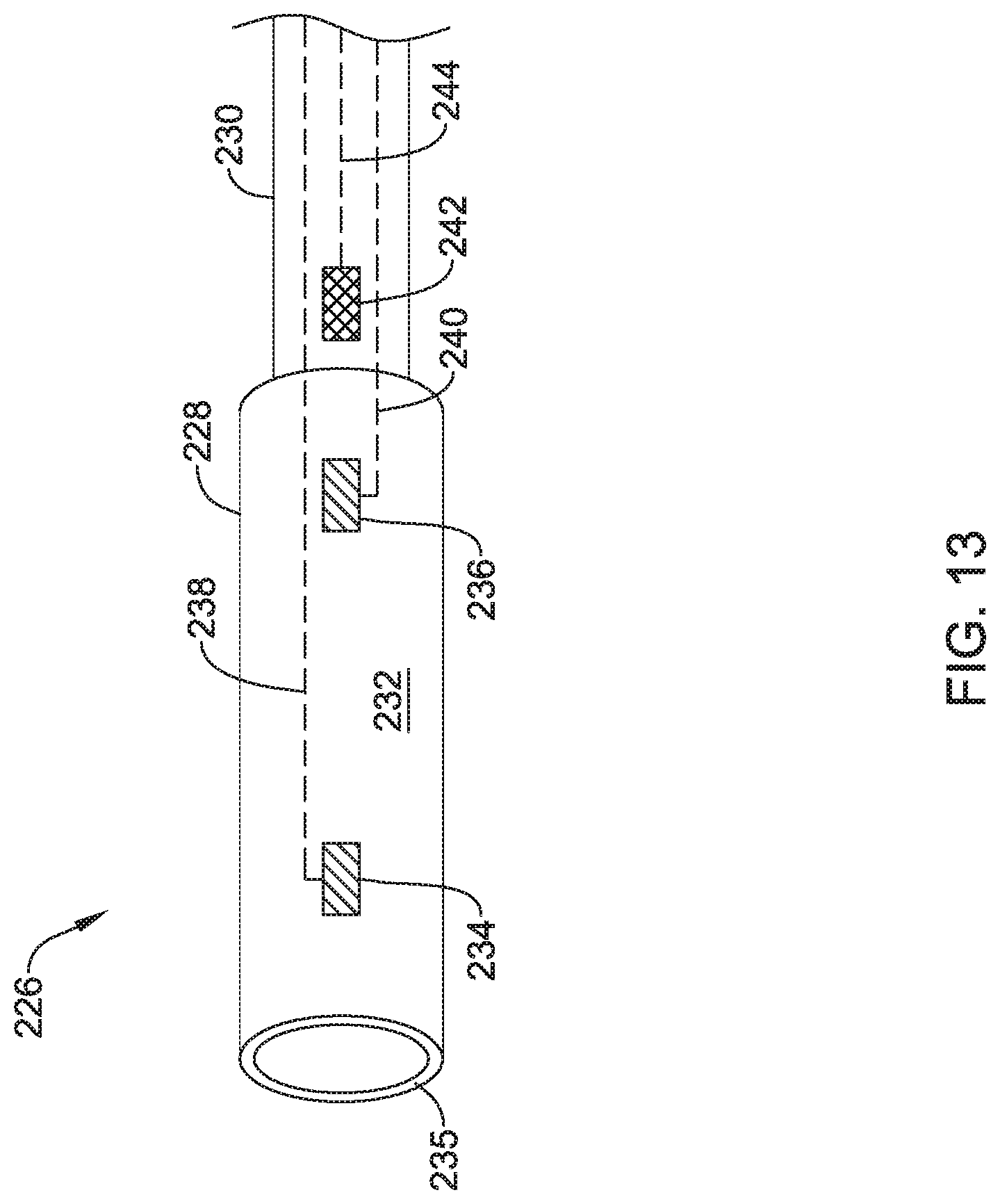
D00019

D00020

D00021

D00022

D00023

D00024

D00025

XML
uspto.report is an independent third-party trademark research tool that is not affiliated, endorsed, or sponsored by the United States Patent and Trademark Office (USPTO) or any other governmental organization. The information provided by uspto.report is based on publicly available data at the time of writing and is intended for informational purposes only.
While we strive to provide accurate and up-to-date information, we do not guarantee the accuracy, completeness, reliability, or suitability of the information displayed on this site. The use of this site is at your own risk. Any reliance you place on such information is therefore strictly at your own risk.
All official trademark data, including owner information, should be verified by visiting the official USPTO website at www.uspto.gov. This site is not intended to replace professional legal advice and should not be used as a substitute for consulting with a legal professional who is knowledgeable about trademark law.