Ultrasonic endovascular catheter
Boyle , et al. Sep
U.S. patent number 10,758,256 [Application Number 15/388,335] was granted by the patent office on 2020-09-01 for ultrasonic endovascular catheter. This patent grant is currently assigned to C. R. Bard, Inc.. The grantee listed for this patent is C.R. Bard, Inc.. Invention is credited to Kevin Boyle, Andrzej J. Chanduszko, Michael Randall, Peng Zheng.


| United States Patent | 10,758,256 |
| Boyle , et al. | September 1, 2020 |
Ultrasonic endovascular catheter
Abstract
A catheter includes a wave guide for transmitting ultrasonic energy from a transducer, and which is also rotated to facilitate enhanced disruption of the concerned obstruction in a transverse direction. Embodiments of waveguide include distal anchors that help focus the energy transmitted to a treatment site, and may also include a deployable filter that may open distal of the obstruction to capture any dislodged debris. Selectively inflatable balloons may cordon off a treatment site, and the wave guide may comprise a tube that may serve the dual purposes of inflating the balloon(s), as well as to transmit ultrasonic energy to an obstruction. A portion of an ultrasonic catheter may include plural curved portions to space an exposed portion of the wave guide away from the catheter body to enhance the vibratory action provided.
| Inventors: | Boyle; Kevin (Scottsdale, AZ), Chanduszko; Andrzej J. (Chandler, AZ), Randall; Michael (Gilbert, AZ), Zheng; Peng (Chandler, AZ) | ||||||||||
|---|---|---|---|---|---|---|---|---|---|---|---|
| Applicant: |
|
||||||||||
| Assignee: | C. R. Bard, Inc. (Franklin
Lakes, NJ) |
||||||||||
| Family ID: | 61007804 | ||||||||||
| Appl. No.: | 15/388,335 | ||||||||||
| Filed: | December 22, 2016 |
Prior Publication Data
| Document Identifier | Publication Date | |
|---|---|---|
| US 20180177515 A1 | Jun 28, 2018 | |
| Current U.S. Class: | 1/1 |
| Current CPC Class: | A61B 17/22004 (20130101); A61B 17/22 (20130101); A61B 17/2202 (20130101); A61B 2017/22051 (20130101); A61B 2017/22062 (20130101); A61M 25/1011 (20130101); A61B 2017/22054 (20130101); A61B 2017/22048 (20130101); A61M 25/0068 (20130101); A61M 2025/1047 (20130101); A61M 25/04 (20130101); A61B 2017/22065 (20130101) |
| Current International Class: | A61B 17/22 (20060101); A61M 25/00 (20060101); A61M 25/10 (20130101); A61M 25/04 (20060101) |
| Field of Search: | ;606/159,169,200 ;604/101.01,101.03,101.05 |
References Cited [Referenced By]
U.S. Patent Documents
| 3296620 | January 1967 | Rodda |
| 3433226 | March 1969 | Boyd |
| 3443226 | May 1969 | Knight |
| 3565062 | February 1971 | Kurls |
| 3585082 | June 1971 | Siller |
| 3612038 | October 1971 | Halligan |
| 3631848 | January 1972 | Muller |
| 3679378 | July 1972 | Van Impe et al. |
| 3719737 | March 1973 | Vaillancourt et al. |
| 3739460 | June 1973 | Addis et al. |
| 3754746 | August 1973 | Thiele |
| 3823717 | July 1974 | Pohlman et al. |
| 3835690 | September 1974 | Leonhardt et al. |
| 3839841 | October 1974 | Amplatz |
| 3896811 | July 1975 | Storz |
| 4016882 | April 1977 | Broadwin et al. |
| 4033331 | July 1977 | Guss et al. |
| 4136700 | January 1979 | Broadwin et al. |
| 4337090 | June 1982 | Harrison |
| 4368410 | January 1983 | Hance et al. |
| 4417578 | November 1983 | Banko |
| 4425115 | January 1984 | Wuchinich |
| 4486680 | December 1984 | Bonnet et al. |
| 4505767 | March 1985 | Quin |
| 4535759 | August 1985 | Polk et al. |
| 4545767 | October 1985 | Suzuki et al. |
| 4565589 | January 1986 | Harrison |
| 4565787 | January 1986 | Bossle et al. |
| 4572184 | February 1986 | Stohl et al. |
| 4664112 | May 1987 | Kensey et al. |
| 4665906 | May 1987 | Jervis |
| 4679558 | July 1987 | Kensey et al. |
| 4700705 | October 1987 | Kensey et al. |
| 4721117 | January 1988 | Mar et al. |
| 4750902 | June 1988 | Wuchinich et al. |
| 4808153 | February 1989 | Parisi |
| 4811743 | March 1989 | Stevens |
| 4827911 | May 1989 | Broadwin et al. |
| 4838853 | June 1989 | Parisi |
| 4854325 | August 1989 | Stevens |
| 4870953 | October 1989 | DonMicheal et al. |
| 4886060 | December 1989 | Wiksell |
| 4920954 | May 1990 | Alliger et al. |
| 4923462 | May 1990 | Stevens |
| 4924863 | May 1990 | Sterzer |
| 4931047 | June 1990 | Broadwin et al. |
| 4936281 | June 1990 | Stasz |
| 4936845 | June 1990 | Stevens |
| 5000185 | March 1991 | Yock |
| 5015227 | May 1991 | Broadwin et al. |
| 5026384 | June 1991 | Farr et al. |
| 5030357 | July 1991 | Lowe |
| 5046503 | September 1991 | Schneiderman |
| 5053008 | October 1991 | Bajaj |
| 5058570 | October 1991 | Idemoto et al. |
| 5076276 | December 1991 | Sakurai et al. |
| 5091205 | February 1992 | Fan |
| 5100423 | March 1992 | Fearnot |
| 5109859 | May 1992 | Jenkins |
| 5114414 | May 1992 | Buchbinder |
| 5116350 | May 1992 | Stevens |
| 5127917 | July 1992 | Niederhauser et al. |
| 5156143 | October 1992 | Bocquet et al. |
| 5163421 | November 1992 | Bernstein et al. |
| 5171216 | December 1992 | Dasse et al. |
| 5180363 | January 1993 | Idemoto et al. |
| 5183470 | February 1993 | Wettermann |
| 5195955 | March 1993 | Don Michael |
| 5215614 | June 1993 | Wijkamp et al. |
| 5217565 | June 1993 | Kou et al. |
| 5221255 | June 1993 | Mahurkar et al. |
| 5226421 | July 1993 | Frisbie et al. |
| 5234416 | August 1993 | Macaulay et al. |
| 5238004 | August 1993 | Sahatjian et al. |
| 5242385 | September 1993 | Strukel |
| 5243997 | September 1993 | Uflacker et al. |
| 5248296 | September 1993 | Alliger |
| 5255669 | October 1993 | Kubota et al. |
| 5267954 | December 1993 | Nita |
| 5269291 | December 1993 | Carter |
| 5269297 | December 1993 | Weng et al. |
| 5269793 | December 1993 | Simpson |
| 5279546 | January 1994 | Mische |
| 5287858 | February 1994 | Hammerslag et al. |
| 5290229 | March 1994 | Paskar |
| 5304115 | April 1994 | Pflueger et al. |
| 5304131 | April 1994 | Paskar |
| 5312328 | May 1994 | Nita et al. |
| 5318014 | June 1994 | Carter |
| 5318570 | June 1994 | Hood et al. |
| 5324255 | June 1994 | Passafaro et al. |
| 5324260 | June 1994 | O'Neill et al. |
| 5325860 | July 1994 | Seward et al. |
| 5326342 | July 1994 | Pflueger et al. |
| 5328004 | July 1994 | Fannin et al. |
| 5329927 | July 1994 | Gardineer et al. |
| 5341818 | August 1994 | Abrams et al. |
| 5342292 | August 1994 | Nita et al. |
| 5344395 | September 1994 | Whalen et al. |
| 5346502 | September 1994 | Estabrook et al. |
| 5362309 | November 1994 | Carter |
| 5368557 | November 1994 | Nita |
| 5368558 | November 1994 | Nita et al. |
| 5376084 | December 1994 | Bacich et al. |
| 5378234 | January 1995 | Hammerslag et al. |
| 5380274 | January 1995 | Nita |
| 5380316 | January 1995 | Aita et al. |
| 5382228 | January 1995 | Nita et al. |
| 5383460 | January 1995 | Jang et al. |
| 5389096 | February 1995 | Aita et al. |
| 5391144 | February 1995 | Sakurai et al. |
| 5397293 | March 1995 | Alliger et al. |
| 5397301 | March 1995 | Pflueger et al. |
| 5405318 | April 1995 | Nita |
| 5409483 | April 1995 | Campbell et al. |
| 5417672 | May 1995 | Nita et al. |
| 5417703 | May 1995 | Brown et al. |
| 5421923 | June 1995 | Clarke et al. |
| 5427118 | June 1995 | Nita et al. |
| 5431168 | July 1995 | Webster, Jr. |
| 5431663 | July 1995 | Carter |
| 5443078 | August 1995 | Uflacker |
| 5447509 | September 1995 | Mills et al. |
| 5449369 | September 1995 | Imran |
| 5451209 | September 1995 | Ainsworth et al. |
| 5462529 | October 1995 | Simpson |
| 5465733 | November 1995 | Hinohara et al. |
| 5474530 | December 1995 | Passafaro et al. |
| 5474531 | December 1995 | Carter |
| 5480379 | January 1996 | La Rosa |
| 5484398 | January 1996 | Stoddard |
| 5487757 | January 1996 | Truckai et al. |
| 5498236 | March 1996 | Dubrul et al. |
| 5507738 | April 1996 | Ciervo |
| 5516043 | May 1996 | Manna et al. |
| 5527273 | June 1996 | Manna et al. |
| 5540656 | July 1996 | Pflueger et al. |
| 5542917 | August 1996 | Nita et al. |
| 5597497 | January 1997 | Dean et al. |
| 5597882 | January 1997 | Schiller et al. |
| 5607421 | March 1997 | Jeevanandam et al. |
| 5611807 | March 1997 | O'Boyle |
| 5618266 | April 1997 | Liprie |
| 5626593 | May 1997 | Imran |
| 5627365 | May 1997 | Chiba et al. |
| 5649935 | July 1997 | Kremer et al. |
| 5658282 | August 1997 | Daw et al. |
| 5685841 | November 1997 | Mackool |
| 5695460 | December 1997 | Siegel et al. |
| 5695507 | December 1997 | Auth et al. |
| 5715825 | February 1998 | Crowley |
| 5720724 | February 1998 | Ressemann et al. |
| 5728062 | March 1998 | Brisken |
| 5738100 | April 1998 | Yagami et al. |
| 5797876 | August 1998 | Spears et al. |
| 5816923 | October 1998 | Milo et al. |
| 5827203 | October 1998 | Nita |
| 5827971 | October 1998 | Hale et al. |
| 5830222 | November 1998 | Makower |
| 5846218 | December 1998 | Brisken et al. |
| 5893838 | April 1999 | Daoud et al. |
| 5895397 | April 1999 | Jang et al. |
| 5902287 | May 1999 | Martin |
| 5904667 | May 1999 | Falwell |
| 5913192 | June 1999 | Parthasarathy et al. |
| 5916192 | June 1999 | Nita et al. |
| 5916912 | June 1999 | Ames et al. |
| 5935142 | August 1999 | Hood |
| 5935144 | August 1999 | Estabrook |
| 5937301 | August 1999 | Gardner et al. |
| 5944737 | August 1999 | Tsonton et al. |
| 5957882 | September 1999 | Nita et al. |
| 5957899 | September 1999 | Spears et al. |
| 5964223 | October 1999 | Baran |
| 5967984 | October 1999 | Chu et al. |
| 5971949 | October 1999 | Levin et al. |
| 5976119 | November 1999 | Spears et al. |
| 5989208 | November 1999 | Nita |
| 5989275 | November 1999 | Estabrook et al. |
| 5997497 | December 1999 | Nita et al. |
| 6004280 | December 1999 | Buck et al. |
| 6007499 | December 1999 | Martin et al. |
| 6007514 | December 1999 | Nita |
| 6022309 | February 2000 | Celliers et al. |
| 6024764 | February 2000 | Schroeppel |
| 6029671 | February 2000 | Stevens et al. |
| 6030357 | February 2000 | Daoud et al. |
| 6051010 | April 2000 | DiMatteo et al. |
| 6113558 | September 2000 | Rosenschein et al. |
| 6123698 | September 2000 | Spears et al. |
| 6142971 | November 2000 | Daoud et al. |
| 6149596 | November 2000 | Bancroft |
| 6159176 | December 2000 | Broadwin et al. |
| 6165127 | December 2000 | Crowley |
| 6165188 | December 2000 | Saadat et al. |
| 6179809 | January 2001 | Khairkhahan et al. |
| 6180059 | January 2001 | Divino, Jr. et al. |
| 6190353 | February 2001 | Makower et al. |
| 6206842 | March 2001 | Tu et al. |
| 6210356 | April 2001 | Anderson et al. |
| 6217543 | April 2001 | Anis et al. |
| 6217565 | April 2001 | Cohen |
| 6217588 | April 2001 | Jerger et al. |
| 6221015 | April 2001 | Yock |
| 6231546 | May 2001 | Milo et al. |
| 6231587 | May 2001 | Makower |
| 6235007 | May 2001 | Divino, Jr. et al. |
| 6241692 | June 2001 | Tu et al. |
| 6241703 | June 2001 | Levin et al. |
| 6248087 | June 2001 | Spears et al. |
| 6277084 | August 2001 | Abele et al. |
| 6283983 | September 2001 | Makower et al. |
| 6287271 | September 2001 | Dubrul et al. |
| 6287285 | September 2001 | Michal et al. |
| 6287317 | September 2001 | Makower et al. |
| 6296620 | October 2001 | Gesswein et al. |
| 6298620 | October 2001 | Hatzinikolas |
| 6302875 | October 2001 | Makower et al. |
| 6309358 | October 2001 | Okubo |
| 6315741 | November 2001 | Martin et al. |
| 6315754 | November 2001 | Daoud et al. |
| 6331171 | December 2001 | Cohen |
| 6346192 | February 2002 | Buhr et al. |
| 6379378 | April 2002 | Werneth et al. |
| 6387109 | May 2002 | Davison et al. |
| 6387324 | May 2002 | Patterson et al. |
| 6394956 | May 2002 | Chandrasekaran et al. |
| 6398736 | June 2002 | Seward |
| 6409673 | June 2002 | Yock |
| 6416533 | July 2002 | Gobin et al. |
| 6423026 | July 2002 | Gesswein et al. |
| 6427118 | July 2002 | Suzuki |
| 6433464 | August 2002 | Jones |
| 6434418 | August 2002 | Neal et al. |
| 6450975 | September 2002 | Brennan et al. |
| 6454757 | September 2002 | Nita et al. |
| 6454997 | September 2002 | Divino, Jr. et al. |
| 6484052 | November 2002 | Visuri et al. |
| 6491707 | December 2002 | Makower et al. |
| 6494891 | December 2002 | Cornish et al. |
| 6494894 | December 2002 | Mirarchi |
| 6500141 | December 2002 | Irion et al. |
| 6508781 | January 2003 | Brennan et al. |
| 6508784 | January 2003 | Shu |
| 6511458 | January 2003 | Milo et al. |
| 6524251 | February 2003 | Rabiner et al. |
| 6533766 | March 2003 | Patterson et al. |
| 6544215 | April 2003 | Bencini et al. |
| 6547754 | April 2003 | Evans et al. |
| 6551337 | April 2003 | Rabiner et al. |
| 6554846 | April 2003 | Hamilton et al. |
| 6555059 | April 2003 | Myrick et al. |
| 6558502 | May 2003 | Divino, Jr. et al. |
| 6562031 | May 2003 | Chandrasekaran et al. |
| 6573470 | June 2003 | Brown et al. |
| 6576807 | June 2003 | Brunelot et al. |
| 6582387 | June 2003 | Derek et al. |
| 6589253 | July 2003 | Cornish et al. |
| 6595989 | July 2003 | Schaer |
| 6596235 | July 2003 | Divino, Jr. et al. |
| 6602467 | August 2003 | Divino, Jr. et al. |
| 6602468 | August 2003 | Patterson et al. |
| 6605217 | August 2003 | Buhr et al. |
| 6607698 | August 2003 | Spears et al. |
| 6610077 | August 2003 | Hancock et al. |
| 6613280 | September 2003 | Myrick et al. |
| 6615062 | September 2003 | Ryan et al. |
| 6616617 | September 2003 | Ferrera et al. |
| 6622542 | September 2003 | Derek et al. |
| 6623448 | September 2003 | Slater |
| 6635017 | October 2003 | Moehring et al. |
| 6650923 | November 2003 | Lesh et al. |
| 6652547 | November 2003 | Rabiner et al. |
| 6660013 | December 2003 | Rabiner et al. |
| 6676900 | January 2004 | Divino, Jr. et al. |
| 6682502 | January 2004 | Bond et al. |
| 6685657 | February 2004 | Jones |
| 6689086 | February 2004 | Nita et al. |
| 6695781 | February 2004 | Rabiner et al. |
| 6695782 | February 2004 | Ranucci et al. |
| 6695810 | February 2004 | Peacock, III et al. |
| 6702748 | March 2004 | Nita et al. |
| 6702750 | March 2004 | Yock |
| 6719715 | April 2004 | Newman et al. |
| 6719725 | April 2004 | Milo et al. |
| 6729334 | May 2004 | Baran |
| 6733451 | May 2004 | Rabiner et al. |
| 6758846 | July 2004 | Goble et al. |
| 6761698 | July 2004 | Shibata et al. |
| 6855123 | February 2005 | Nita |
| 6866670 | March 2005 | Rabiner et al. |
| 6936025 | August 2005 | Evans et al. |
| 6936056 | August 2005 | Nash et al. |
| 6942620 | September 2005 | Nita et al. |
| 6942677 | September 2005 | Nita et al. |
| 6955680 | October 2005 | Satou et al. |
| 7004173 | February 2006 | Sparks et al. |
| 7004176 | February 2006 | Lau |
| 7056294 | June 2006 | Khairkhahan et al. |
| 7131983 | November 2006 | Murakami |
| 7137963 | November 2006 | Nita et al. |
| 7149587 | December 2006 | Wardle et al. |
| 7150853 | December 2006 | Lee et al. |
| 7166098 | January 2007 | Steward et al. |
| 7220233 | May 2007 | Nita et al. |
| 7267650 | September 2007 | Chow et al. |
| 7297131 | November 2007 | Nita |
| 7335180 | February 2008 | Nita et al. |
| 7341569 | March 2008 | Soltani et al. |
| 7384407 | June 2008 | Rodriguez et al. |
| 7393338 | July 2008 | Nita |
| 7421900 | September 2008 | Karasawa et al. |
| 7425198 | September 2008 | Moehring et al. |
| 7494468 | February 2009 | Rabiner et al. |
| 7503895 | March 2009 | Rabiner et al. |
| 7540852 | June 2009 | Nita |
| 7604608 | October 2009 | Nita et al. |
| 7621902 | November 2009 | Nita et al. |
| 7621929 | November 2009 | Nita et al. |
| 7648478 | January 2010 | Soltani et al. |
| 7771358 | August 2010 | Moehring et al. |
| 7771452 | August 2010 | Pal et al. |
| 7775994 | August 2010 | Lockhart |
| 7776025 | August 2010 | Bobo, Jr. |
| 7819013 | October 2010 | Chan et al. |
| 7850623 | December 2010 | Griffin et al. |
| 7918819 | April 2011 | Karmarkar et al. |
| 7935108 | May 2011 | Baxter et al. |
| 7938819 | May 2011 | Kugler et al. |
| 7955293 | June 2011 | Nita et al. |
| 8043251 | October 2011 | Nita et al. |
| 8083727 | December 2011 | Kugler et al. |
| 8133236 | March 2012 | Nita |
| 8221343 | July 2012 | Nita et al. |
| 8226566 | July 2012 | Nita |
| 8246643 | August 2012 | Nita |
| 8257378 | September 2012 | O'Connor |
| 8308677 | November 2012 | Nita et al. |
| 8414543 | April 2013 | McGuckin, Jr. et al. |
| 8506519 | August 2013 | Nita |
| 8613751 | December 2013 | Nita et al. |
| 8617096 | December 2013 | Nita et al. |
| 8632560 | January 2014 | Pal et al. |
| 8647296 | February 2014 | Moberg et al. |
| 8663259 | March 2014 | Levine et al. |
| 8668709 | March 2014 | Nita et al. |
| 8690818 | April 2014 | Bennett et al. |
| 8690819 | April 2014 | Nita et al. |
| 8764700 | July 2014 | Zhang et al. |
| 8790291 | July 2014 | Nita et al. |
| 8974446 | March 2015 | Nguyen et al. |
| 9107590 | August 2015 | Hansmann et al. |
| 9265520 | February 2016 | Nita |
| 9282984 | March 2016 | Nita |
| 9314258 | April 2016 | Nita et al. |
| 9381027 | July 2016 | Nita et al. |
| 9421024 | August 2016 | Nita et al. |
| 9770250 | September 2017 | Nita et al. |
| 10004520 | June 2018 | Nita et al. |
| 2002/0022858 | February 2002 | Demond |
| 2002/0029054 | March 2002 | Rabiner et al. |
| 2002/0049409 | April 2002 | Noda et al. |
| 2002/0077550 | June 2002 | Rabiner et al. |
| 2002/0188276 | December 2002 | Evans |
| 2003/0009153 | January 2003 | Brisken et al. |
| 2003/0036705 | February 2003 | Hare et al. |
| 2003/0040762 | February 2003 | Dorros et al. |
| 2003/0176791 | September 2003 | Rabiner et al. |
| 2003/0199817 | October 2003 | Thompson et al. |
| 2003/0216732 | November 2003 | Truckai et al. |
| 2003/0225332 | December 2003 | Okada et al. |
| 2004/0024393 | February 2004 | Nita et al. |
| 2004/0164030 | August 2004 | Lowe et al. |
| 2004/0167511 | August 2004 | Buehlmann |
| 2005/0033311 | February 2005 | Guldfeldt et al. |
| 2005/0113688 | May 2005 | Nita et al. |
| 2005/0149110 | July 2005 | Wholey |
| 2005/0228286 | October 2005 | Messerly et al. |
| 2006/0074441 | April 2006 | McGuckin, Jr. |
| 2006/0206039 | September 2006 | Wilson et al. |
| 2006/0264809 | November 2006 | Hansmann et al. |
| 2007/0037119 | February 2007 | Pal |
| 2008/0071343 | March 2008 | Mayberry et al. |
| 2008/0208084 | August 2008 | Horzewski et al. |
| 2008/0221506 | September 2008 | Rodriguez et al. |
| 2009/0264770 | October 2009 | Liu |
| 2010/0023037 | January 2010 | Nita et al. |
| 2011/0105960 | May 2011 | Wallace |
| 2011/0130834 | June 2011 | Wilson et al. |
| 2011/0237982 | September 2011 | Wallace |
| 2011/0313328 | December 2011 | Nita |
| 2012/0130475 | May 2012 | Shaw |
| 2012/0311844 | December 2012 | Nita et al. |
| 2012/0330196 | December 2012 | Nita |
| 2014/0236118 | August 2014 | Unser et al. |
| 2014/0243712 | August 2014 | Humayun et al. |
| 2015/0133918 | May 2015 | Sachar |
| 2015/0150571 | June 2015 | Nita et al. |
| 2015/0157443 | June 2015 | Hauser et al. |
| 2015/0190660 | July 2015 | Sarge et al. |
| 2015/0297258 | October 2015 | Escudero et al. |
| 2015/0359651 | December 2015 | Wubbeling |
| 2016/0128717 | May 2016 | Nita |
| 2016/0183956 | June 2016 | Nita |
| 2016/0271362 | September 2016 | Van Liere |
| 2016/0338722 | November 2016 | Nita et al. |
| 2017/0065288 | March 2017 | Imai |
| 2017/0354428 | December 2017 | Nita et al. |
| 2007240154 | Jan 2008 | AU | |||
| 2256127 | May 1974 | DE | |||
| 2438648 | Feb 1976 | DE | |||
| 8910040 | Dec 1989 | DE | |||
| 3821836 | Jan 1990 | DE | |||
| 4042435 | Feb 1994 | DE | |||
| 0005719 | Dec 1979 | EP | |||
| 0316789 | May 1989 | EP | |||
| 0316796 | May 1989 | EP | |||
| 0376562 | Jul 1990 | EP | |||
| 0379156 | Jul 1990 | EP | |||
| 0394583 | Oct 1990 | EP | |||
| 0443256 | Aug 1991 | EP | |||
| 0472368 | Feb 1992 | EP | |||
| 0541249 | May 1993 | EP | |||
| 0820728 | Jan 1998 | EP | |||
| 1323481 | Jul 2003 | EP | |||
| 1106957 | Mar 1968 | GB | |||
| H2-7150 | Oct 1988 | JP | |||
| 01-099547 | Apr 1989 | JP | |||
| 6086822 | Mar 1994 | JP | |||
| H07500752 | Jan 1995 | JP | |||
| 7116260 | May 1995 | JP | |||
| 9-503137 | Mar 1997 | JP | |||
| 10-216140 | Aug 1998 | JP | |||
| 2000-291543 | Oct 2000 | JP | |||
| 2001-104356 | Apr 2001 | JP | |||
| 2001-321388 | Nov 2001 | JP | |||
| 2002-186627 | Jul 2002 | JP | |||
| 2005-253874 | Sep 2005 | JP | |||
| 2006-522644 | Oct 2006 | JP | |||
| 2007512087 | May 2007 | JP | |||
| 2007520255 | Jul 2007 | JP | |||
| 8705739 | Sep 1987 | WO | |||
| 8705793 | Oct 1987 | WO | |||
| 8906515 | Jul 1989 | WO | |||
| 9001300 | Feb 1990 | WO | |||
| 9004362 | May 1990 | WO | |||
| 9107917 | Jun 1991 | WO | |||
| 9211815 | Jul 1992 | WO | |||
| 9308750 | May 1993 | WO | |||
| 9316646 | Sep 1993 | WO | |||
| 9412140 | Jun 1994 | WO | |||
| 9414382 | Jul 1994 | WO | |||
| 9508954 | Apr 1995 | WO | |||
| 9509571 | Apr 1995 | WO | |||
| 9515192 | Jun 1995 | WO | |||
| 9635469 | Nov 1996 | WO | |||
| 9705739 | Feb 1997 | WO | |||
| 9721462 | Jun 1997 | WO | |||
| 9745078 | Dec 1997 | WO | |||
| 9827874 | Jul 1998 | WO | |||
| 9835721 | Aug 1998 | WO | |||
| 9851224 | Nov 1998 | WO | |||
| 9852637 | Nov 1998 | WO | |||
| 9925412 | May 1999 | WO | |||
| 0053341 | Sep 2000 | WO | |||
| 0067830 | Nov 2000 | WO | |||
| 03039381 | May 2003 | WO | |||
| 2004012609 | Feb 2004 | WO | |||
| 2004093736 | Nov 2004 | WO | |||
| 2004112888 | Dec 2004 | WO | |||
| 2005053769 | Jun 2005 | WO | |||
| 2006049593 | May 2006 | WO | |||
| 2014022716 | Feb 2014 | WO | |||
| 2014105754 | Jul 2014 | WO | |||
| WO2014105754 | Jul 2014 | WO | |||
| WO2016064077 | Apr 2016 | WO | |||
Other References
|
Circulation Catheter-Based Ultrasound Thrombolysis Shake, Rattle, and Reperfuse Paul G. Yock, Peter J. Fitzgerald https://doi.org/10.1161/01.CIR.95.6.1360. cited by applicant . Japanese Office Action for Japanese Application No. 2010-134566, dated Mar. 2, 2012. cited by applicant . Sehgal, et al., Ultrasound-Assisted Thrombolysis, Investigative Radiology, 1993, vol. 28, Issue 10, pp. 939-943. cited by applicant . Siegel, et al., "In Vivo Ultrasound Arterial Recanalization of Atherosclerotic Total Occlusions", Journal of the American College of Cardiology, Feb. 1990, vol. 15, No. 2, pp. 345-351. cited by applicant . "What is Electron Beam Curing?" downloaded from web on Nov. 14, 2002, 4 pages total. <http://www.ms.oml.gov/researchgroups/composites/new%20orccmt%20pages/- pages/ebwha>. cited by applicant . Noone, D.: Experimental and Numerical Investigation of Wire Waveguides for Therapeutic Ultrasound Angioplasty. M.Eng. Dublin City University. 2008. cited by applicant . Definition of the term "connected", retrieved on Sep. 21, 2013. <www.thefreedictionary.com/connected> 1 page total. cited by applicant . Supplemental European Search Report dated Nov. 5, 2009 for European Application No. EP03766931. cited by applicant . International Search Report dated Oct. 28, 2003 for PCT Application No. PCT/US2003/023468. cited by applicant . Extended European Search Report dated Mar. 22, 2012 for European Application No. EP11188799. cited by applicant . International Search Report dated Dec. 23, 2005 for PCT Application No. PCT/US2004/019378. cited by applicant . Extended European Search Report for Patent Application No. 06718204.8, dated May 30, 2012. cited by applicant . International Search Report dated Aug. 1, 2013 for PCT Application No. PCT/US2013/053306. cited by applicant . International Preliminary Report dated Aug. 1, 2013 for PCT Application No. PCT/US2013/053306. cited by applicant . Written Opinion dated Aug. 1, 2013 for PCT Application No. PCT/US2013/053306. cited by applicant . Supplemental European Search Report dated Apr. 29, 2009 for European Application No. EP 04711207.3. cited by applicant . Calhoun et al., "Electron-Beam Systems for Medical Device Sterilization", downloaded from web on Oct. 8, 2002 <http://www.devicelink.com/mpb/archive/97/07/002.html> 7 pages total. cited by applicant . Definition of the term "coupled", retrieved on May 18, 2013. <http://www.merriam-webster.com/dictionary/couple> 1 page total. cited by applicant . "E-Beam Theory" RDI-IBA Technology Group, downloaded from web on Oct. 8, 2002 <http://www.e-beamrdi/EbeamTheory.htm> 2 pages total. cited by applicant . Office Action dated May 20, 2010 from Japanese Application No. 2006-541200 filed on Oct. 25, 2004. cited by applicant . Office Action dated Oct. 11, 2012 from Japanese Application No. 2010-181956. cited by applicant . Extended European Search Report dated Mar. 5, 2012 for European Application No. 12153606.4-1269. cited by applicant . Margaret Fyfe et al., Mast cell degranulation and increased vascular permeability induced by `therapeutic` ultrasound in the rate ankle joint, Br. J. exp. Path., 1984, vol. 65, pp. 671-676. cited by applicant . "Irradiation, Biological, and Other Technologies: E-beam, Biological, and Sharps Treatment Systems", Non-Incineration Medical Waste Treatment Technologies, Aug. 2001, Chapter 9, pp. 69-74, Health Care Without Harm, Washington, DC. cited by applicant. |
Primary Examiner: Ho; Tan-Uyen T
Assistant Examiner: Igboko; Chima U
Claims
What is claimed:
1. An apparatus for performing an endovascular procedure, comprising: a catheter body including a lumen extending along a proximal end portion and a distal end portion, the catheter body having at the distal end portion opposed portions, the proximal end portion being positioned along a central longitudinal axis; an ultrasonic wave guide including a first portion positioned within the lumen and a second exposed portion, wherein the opposed portions at the distal end portion of the catheter body are spaced directly across the central longitudinal axis and are spaced in a transverse direction from the central longitudinal axis, wherein a gap is defined between the opposed portions, the second exposed portion of the ultrasonic wave guide extends in the gap, each of the opposed portions has an entire length, the opposed portions are reflectively symmetrical about the central longitudinal axis, each opposed portion curves along the central longitudinal axis along the entire length, and wherein the opposed portions provide a centering function for the ultrasonic wave guide at a treatment site; and an ultrasonic transducer coupled to the ultrasonic wave guide for vibrating the ultrasonic wave guide at an ultrasonic frequency.
2. An apparatus for performing an endovascular procedure, comprising: an ultrasonic catheter positioned along a central longitudinal axis, the ultrasonic catheter including a proximal end portion, the proximal end portion including a lumen, and the ultrasonic catheter including opposed portions distal to the proximal end portion, wherein the opposed portions are spaced in a transverse direction from the central longitudinal axis, wherein the opposed portions define a transverse gap; and an ultrasonic wave guide including a first portion positioned within the lumen and a second exposed portion, the ultrasonic wave guide being positioned along the central longitudinal axis, the second exposed portion being exposed in the transverse gap between the opposed portions of the ultrasonic catheter, the second exposed portion extending in the transverse gap between the opposed portions of the ultrasonic catheter, wherein the opposed portions are reflectively symmetrical about the central longitudinal axis, the opposed portions curve along the central longitudinal axis, and wherein the opposed portions provide a centering function for the ultrasonic wave guide at a treatment site.
3. The apparatus of claim 2, further including an actuator having an ultrasonic transducer coupled to the ultrasonic wave guide for vibrating the ultrasonic wave guide at an ultrasonic frequency.
4. The apparatus of claim 2, wherein the opposed portions curve along the central longitudinal axis of the ultrasonic catheter in opposite directions to define the transverse gap.
5. The apparatus of claim 2, wherein an ultrasonic catheter further includes a distal tip through which the ultrasonic wave guide extends.
6. The apparatus of claim 2, wherein an ultrasonic catheter further includes a distal tip, wherein the ultrasonic wave guide extends to the distal tip.
7. The apparatus of claim 2, wherein an ultrasonic catheter further includes a distal tip, wherein the ultrasonic wave guide is connected to the distal tip of the ultrasonic catheter.
8. An apparatus for performing an endovascular procedure, comprising: a catheter body including a lumen extending along a proximal end portion and a distal end portion, the proximal end portion being positioned along a central longitudinal axis, the catheter body having at the distal end portion opposed portions that curve along the central longitudinal axis, the opposed portions comprise a first opposed portion and a second opposed portion, the first opposed portion is spaced across the central longitudinal axis from the second opposed portion, the opposed portions defining a space between; an ultrasonic wave guide including a first portion positioned within the lumen and a second exposed portion, the second exposed portion extending through the space, the ultrasonic wave guide having a total length, wherein the second exposed portion has a second exposed portion entire length, the total length of the ultrasonic wave guide is positioned along the central longitudinal axis, wherein the opposed portions provide a centering function for the ultrasonic wave guide at a treatment site; and an ultrasonic transducer coupled to the ultrasonic wave guide for vibrating the ultrasonic wave guide at an ultrasonic frequency, wherein the opposed portions are reflectively symmetrical about the central longitudinal axis for an entirety of the second exposed portion entire length.
Description
TECHNICAL FIELD
This document relates generally to the art of endovascular procedures and, more particularly, to an endovascular catheter using ultrasonic energy to perform a medical procedure, such as an atherectomy or thrombectomy.
BACKGROUND
Ultrasonic catheters have been proposed. An example of such a catheter is shown in U.S. Pat. No. 7,540,852, the disclosure of which is fully incorporated herein by reference. While this catheter achieves the desired result of providing enhanced disruption of blood vessel obstructions, the present disclosure proposes certain modifications or improvements to enhance the results achieved during an endovascular procedure in terms of clearing an obstruction from a vessel (such as, for example, an atherectomy for removing atherosclerosis from a blood vessel or or a thrombectomy for dissolving a thrombus or embolus).
SUMMARY
Summarizing the disclosure, an improved ultrasonic catheter for enhancing an endovascular procedure, such as an atherectomy or thrombectomy. The catheter may include a wave guide for transmitting ultrasonic energy from a transducer, and which is also rotated by a motor to facilitate enhanced disruption of the concerned obstruction in a transverse direction. Embodiments of waveguide include distal anchors that help prevent movement of the distal end, and may also include a deployable filter that may open distal of the obstruction to capture any dislodged debris (which may be suctioned out through a lumen in an associated catheter body).
To help improve the treatment regimen, an ultrasonic catheter may also be provided with barriers, such as inflatable balloons, to cordon off a treatment site. In any embodiment including one or more balloons, the waveguide may serve the dual purposes of inflating the balloon(s), as well as transmitting ultrasonic energy to an obstruction. To further enhance the energy transmission for treatment purposes, a portion of the ultrasonic catheter may include one or more curves (possibly selectively actuated by way of a remote control) in order to space an exposed portion of the wave guide away from the catheter body to thereby enhance the vibratory action provided.
According to a first specific aspect of the disclosure, an apparatus for performing an endovascular procedure is provided. The apparatus comprises a catheter and an associated wave guide having a distal end portion adapted for extending from the lumen of the catheter. An actuator for vibrating and rotating the wave guide is also provided.
In one embodiment, the actuator comprises an ultrasonic transducer for vibrating the wave guide and a motor for rotating the ultrasonic transducer or the wave guide. The catheter may include a lumen for receiving a proximal portion of the wave guide, which may include a distal portion having at least one curve or bend. A connector connected to the catheter may at least partially include the actuator, and a controller may be provided for controlling the amount and direction of rotation of the wave guide.
According to a further aspect of the disclosure, an apparatus for performing an endovascular procedure comprises a catheter and a wave guide associated with the catheter. The wave guide includes a distal end with an anchor for anchoring the wave guide. An actuator is also provided for vibrating the wave guide.
In one embodiment, the anchor comprises a centering coil. In another embodiment, the anchor comprises one or more weights. In still another embodiment, the anchor comprises an anchoring cone, and in another is an inflatable balloon. The wave guide may comprise a wire.
Still a further aspect of the disclosure pertains to an apparatus for performing an endovascular procedure. The apparatus comprises a catheter and a wave guide associated with the catheter. The wave guide includes a distal end having a filter with an open end facing a proximal end of the wave guide. An actuator is also provided for vibrating the wave guide.
In one embodiment, the filter comprises a deployable frame supporting a flexible material. The deployable frame may comprise a shape memory material. The flexible material may comprise a porous mesh or similar material for performing a filtering function.
Yet a further aspect of the disclosure pertains to an apparatus for performing an endovascular procedure. The apparatus comprises a catheter including a lumen and supporting a first inflatable balloon. A wave guide includes a distal end portion projecting from the lumen proximally of the first inflatable balloon. An actuator is provided for actuating the wave guide.
In one embodiment, the wave guide comprises a tube for supplying inflation fluid to the first balloon. The apparatus may further include a second balloon, and the wave guide may comprise a wire extending between the first and second balloons. A portion of the catheter between the first and second balloons may comprise one or more openings for transmitting fluid to or from a portion of a vessel bounded by the first and second balloons when inflated.
Another aspect of the disclosure pertains to an apparatus for performing an endovascular procedure. The apparatus comprises a catheter including a lumen extending along a proximal end portion and a distal end portion. A wave guide includes a first portion positioned within the lumen, a second exposed portion, and a third portion connected to the distal end portion of the catheter. An actuator is provided for vibrating at least the second exposed portion of the wave guide.
In a further aspect, the disclosure pertains to an apparatus for performing an endovascular procedure. The apparatus comprises a catheter including a proximal end portion including a lumen and opposed portions. A wave guide includes a first portion positioned within the lumen and a second exposed portion positioned along the opposed portions of the catheter.
In one embodiment, an actuator is provided for vibrating the wave guide. The catheter may also include opposed curved portions. The wave guide may be positioned in a gap or space between the opposed curved portions, which may surround the wave guide (e.g., core wire or tube).
Yet another aspect of the disclosure pertains to an apparatus for performing an endovascular procedure. A catheter supports a first inflatable balloon. A wave guide is associated with the catheter and includes a lumen. An actuator, such as an ultrasonic transducer, is provided for coupling to a proximal end of the wave guide.
In one embodiment, the apparatus further includes a second inflatable balloon supported by the tube proximally of the first inflatable balloon. A tip may also be provided for sealing a distal end of the tube. The tip may include a guidewire lumen.
BRIEF DESCRIPTION OF THE DRAWING FIGURES
The accompanying drawing figures incorporated herein and forming a part of the specification, illustrate several aspects of the ultrasonic endovascular catheter and, together with the description, serve to explain certain principles thereof. In the drawing figures:
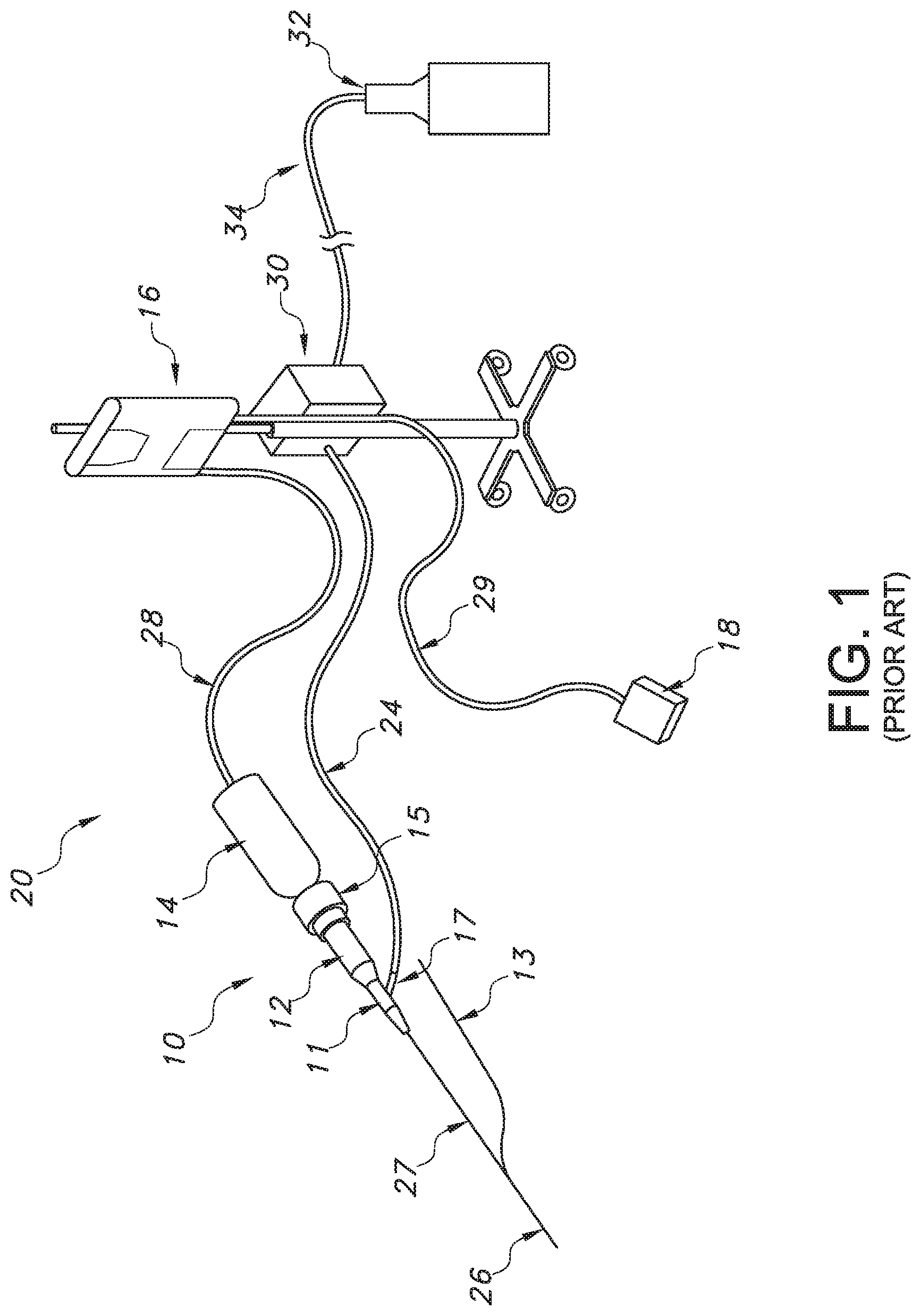
FIG. 1 is a schematic view of a prior art catheter system including an ultrasonic catheter;
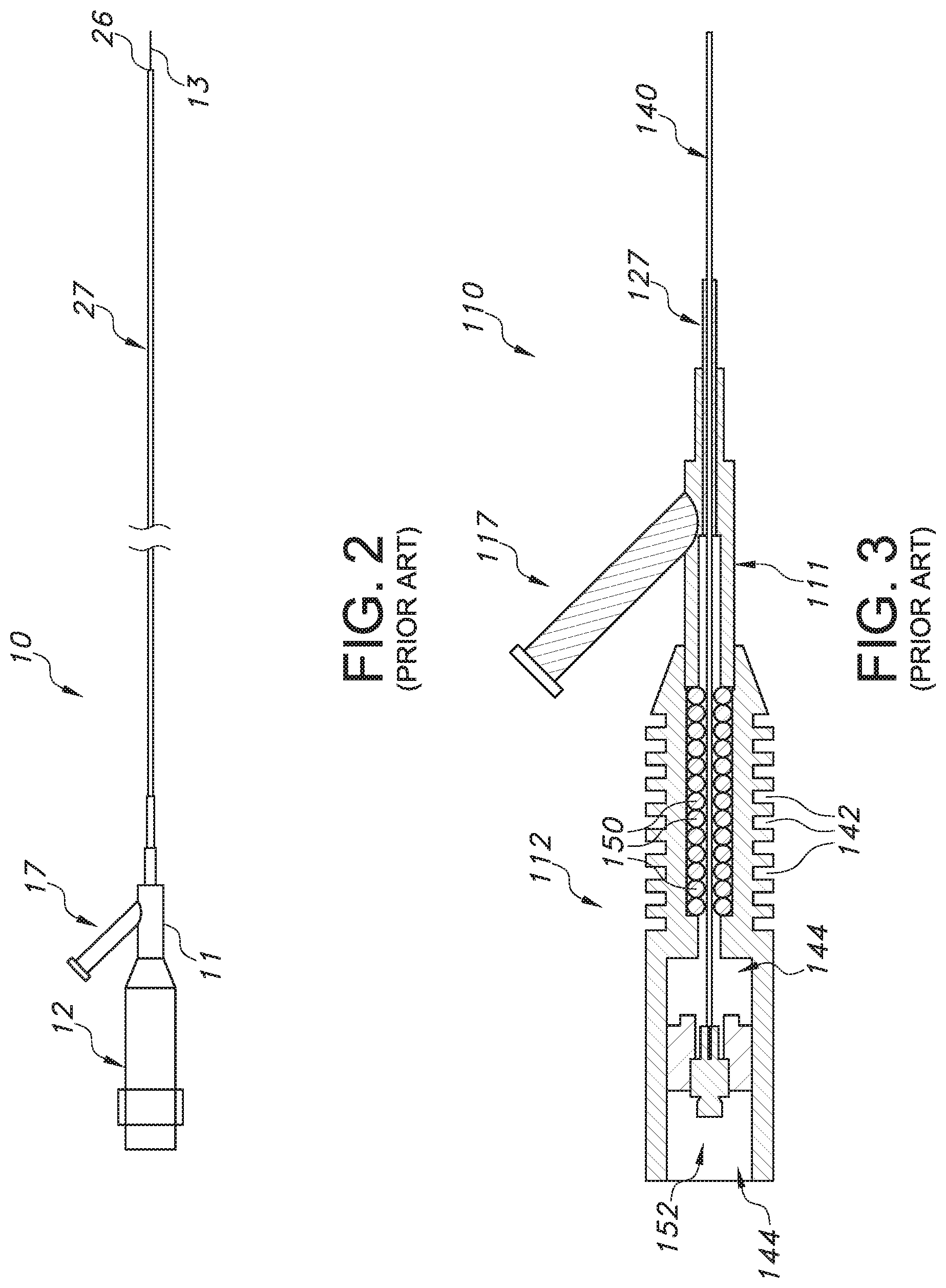
FIG. 2 is a side view illustrating a general layout of a prior art catheter;
FIG. 3 is a partially cross-sectional, partially cutaway view of a catheter including an ultrasonic wave guide;
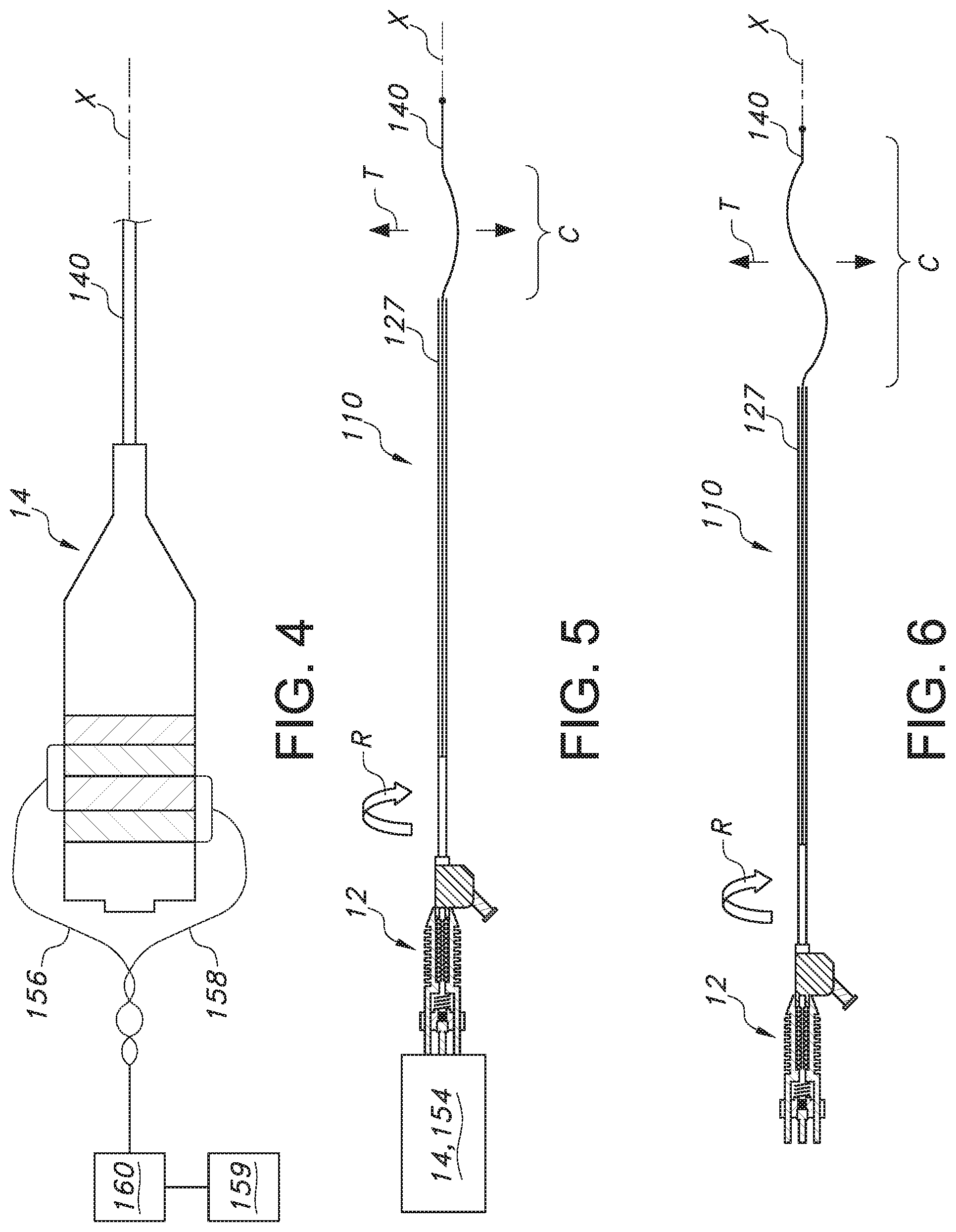
FIG. 4 is a partially cutaway, schematic view illustrating an actuator for both vibrating and rotating the wave guide;
FIGS. 5 and 6 are views illustrating the wave guide including different curved portions for moving in the transverse direction to enhance the treatment provided in terms of dissolving an obstruction in a vessel receiving the wave guide;
FIGS. 7, 8, and 9 are side views illustrating various anchors placed at a distal end portion of an ultrasonic wave guide;
FIGS. 10, 11, and 12 are side views of various filters placed at a distal end portion of an ultrasonic wave guide;
FIGS. 13, 14 and 15 illustrate an embodiment of an ultrasonic catheter including first and second inflatable balloons for isolating a treatment site to be treated by an exposed portion of a wave guide;
FIGS. 16 and 17 schematically illustrated another ultrasonic catheter including a tube that may transmit ultrasonic energy and also serve to inflate one or more associated balloons; and
FIG. 18 illustrates still a further embodiment of an ultrasonic catheter including a plurality of curved portions spaced from a wave guide for transmitting energy to a treatment site.
Reference will now be made in detail to the presently disclosed embodiments of the inventive aspects of the ultrasonic endovascular catheter, examples of which are illustrated in the accompanying drawing figures.
DETAILED DESCRIPTION
Ultrasound or ultrasonic catheters provide for disruption of occlusions in blood vessels, such as for example, plaques, clots, lesions, or like objects that hinder blood flow. Catheters generally include a catheter body (shaft), an ultrasonic energy transmission member disposed within the catheter body and a distal head coupled with the energy transmission member and disposed at or near the distal end of the catheter body. The ultrasonic wave guide transmits ultrasonic energy from an ultrasonic transducer to the distal end of the catheter, causing it to vibrate and, thus, disrupt dissolve, or debulk vascular occlusions (which procedures are generally called atherectomies or thrombectomies). A number of improved features of such an ultrasonic catheter are outlined more fully in the following description.
Referring now to FIG. 1, one embodiment of an ultrasonic catheter system 20 includes an ultrasound or ultrasonic catheter 10 and an energy source 16 (which may comprise an ultrasonic generator). Catheter 10 includes a distal end 26 for disrupting occlusions, a catheter shaft or body 27, and a proximal connector 12 for coupling catheter 10 with an ultrasonic transducer 14. Ultrasonic transducer 14 is coupled with source 16 via a connector 28, and generator is coupled with a control, such as a foot-actuated on/off switch 18 via another connector 29. Source 16 provides energy to transducer 14 and, thus, to ultrasonic catheter 10.
Catheter 10 further includes an ultrasonic wave guide (or "core wire"--not shown in FIG. 1) that extends through the catheter body 27 and transmits energy from the transducer 14 to the distal end 26. Some embodiments of catheter 10 include a guidewire, which in FIG. 1 is shown as a so-called "rapid exchange" guidewire 13 and guidewire port, while other embodiments include a proximal guidewire port for over the wire guidewire delivery. In some embodiments, transducer 14 further includes a coupler 15 for coupling the catheter 10 to transducer 14. Connectors 28, 29 may comprise an electric cord or cable or any other suitable connecting devices for coupling on/off switch 18, source 16 and transducer 14. In an alternative embodiment, on/off switch 18 is located on source 16.
In addition to proximal connector 12, ultrasonic catheter 10 may include one or more other various components, such as a Y-connector 11 including a fluid inlet port 17 (or aperture) for passage of irrigation fluid. Inlet port 17 may be removably coupled with an irrigation tube 24, which in one embodiment may be coupled with a fluid refrigerator 30. The refrigerator 30 may, in turn, be coupled with a fluid container 32 via a connector tube 34. This arrangement may be used for introducing one or more fluids into catheter 10. Fluid may be used to cool any part of the device, such as the ultrasonic wave guide, thus helping reduce wear and tear on the catheter 10. In some embodiments, fluid inlet port 17 is located farther proximally on proximal connector 12, to allow fluid to be applied within connector 12. In some embodiments, refrigerated fluid is used, while in other embodiments irrigation fluid may be kept at room temperature. In various embodiments, oxygen supersaturated fluid, lubricious fluid, or any other suitable fluid or combination of fluids may be used, and again, such fluids may be refrigerated or kept room temperature. In an alternative embodiment to that shown in FIG. 1, refrigerator 30 and fluid container 32 are combined in one unit.
Generally, catheter 10 may include any suitable number of side-arms or ports for passage of a guidewire, application of suction, infusing and/or withdrawing irrigation fluid, dye and/or the like, or any other suitable ports or connections. Also, ultrasonic catheters 10 per the disclosure may be used with any suitable proximal devices, such as any suitable ultrasonic transducer 14, energy source 16, coupling device(s) and/or the like. Therefore, the exemplary embodiment shown in FIG. 1 and any following descriptions of proximal apparatus or systems for use with ultrasonic catheters 10 should not be interpreted to limit the scope of the appended claims.
Referring now to FIG. 2, an enlarged view of catheter 10 is shown. Proximal connector 12, Y-connector 11, inlet port 17, catheter body 27, distal end 26 and guidewire 13 are all shown. Catheter body 27 is generally a flexible, tubular, elongate member, having any suitable diameter and length for reaching a vascular occlusion for treatment. In one embodiment, for example, catheter body 27 preferably has an outer diameter of between about 0.5 mm and about 5.0 mm. In other embodiments, as in catheters intended for use in relatively small vessels, catheter body 27 may have an outer diameter of between about 0.25 mm and about 2.5 mm. Catheter body 27 may also have any suitable length. As discussed briefly above, for example, some ultrasonic catheters have a length in the range of about 150 cm. However, any other suitable length may be used without departing from the scope of the present disclosure.
Referring now to FIG. 3, a proximal portion of one embodiment of an ultrasonic catheter 110 is shown in cross-section. An ultrasonic wave guide 140 extends from a sonic connector 152 distally to a distal end (not shown) of catheter 110. A catheter body 127 of catheter 110 is shown only in part, whereas catheter body typically extends distally to (or near) the distal end of catheter 110, with the wave guide 140 also extending a particularly long distance (e.g., 30 centimeters or greater, and typically between about 15 centimeters and 30 centimeters). The catheter body 127 may be a constant diameter, or may have a variable diameter from the proximal to the distal end (such as, for example, wider in diameter at the proximal end near the point of entering the vasculature than at the distal end, where the vessel is narrower)
Catheter 110 also includes a proximal housing 112 (or "proximal connector"), having an inner bore 144 (or "inner cavity") in which sonic connector 152, a portion of ultrasonic wave guide 140 and one or more vibration absorbers 150 reside. Housing 112 is coupled with a Y-connector 111, which includes a fluid inlet port 117 (or aperture), and Y-connector 111 is coupled with catheter body 127.
In various embodiments, housing 112 may suitably include one or more surface features 142 for increasing the overall surface area of the outer surface of housing 112. Increased surface area enhances the ability of housing 112 to dissipate heat generated by ultrasonic wave guide 140 out of catheter 110. Surface features 142 may have any suitable size or shape, such as ridges, jags, undulations, grooves or the like, and any suitable number of surface features 142 may be used. Additionally, housing 112 may be made of one or more heat dissipating materials, such as aluminum, stainless steel, any other conductive metal(s), or any suitable non-metallic conductive material(s).
In most embodiments, ultrasonic wave guide 140, such as wire, extends longitudinally through a lumen of catheter body 127 to transmit ultrasonic energy from an ultrasonic transducer 14 (not shown in FIGS. 2 and 3), connected to the proximal end of proximal housing 112, to the distal end of catheter 110. Wave guide 140 may be formed of any material capable of effectively transmitting ultrasonic energy from the ultrasonic transducer 14 to the distal end of catheter body 127, including but not limited to metals such as pure titanium or aluminum, titanium or aluminum alloys, or shape memory materials (such as nitinol), and may be coated (such as using a polymeric material). Again, additional details of ultrasonic wave guides 140 may be found in the patent applications incorporated by reference. Similarly, reference may be made to the incorporated patent applications for descriptions of housing 112, sonic connector 152, vibration absorbers 150, Y-connector 111 and the like. For example, housing 112 and other features are described in detail in Ser. No. 10/722,209, filed Nov. 24, 2003, entitled "Steerable Ultrasound Catheter," incorporated herein by reference.
Ultrasonic wave guide 140 typically passes from a sonic connector 152, through bore 144 and Y-connector 111, and then through catheter body 127. Fluid inlet port 117 is in fluid communication with a lumen in Y-connector, which is in fluid communication with a lumen extending through catheter body 127. Thus, fluid introduced into fluid inlet port 117 is typically free to flow into and through catheter body 127 to contact ultrasonic wave guide 140. Fluid may flow out of catheter body 127 through apertures in the distal head (not shown) or through any other suitable apertures or openings, such as apertures located in catheter body 127 itself. Any suitable fluid may be passed through fluid inlet port 117 and catheter body 127, such as refrigerated fluid, lubricious fluid, super-saturated saline or contrast/saline mixture, or the like. Cooling and/or lubricating ultrasonic wave guide 140 may reduce friction and/or wear and tear of ultrasonic wave guide 140, thus prolonging the useful life of ultrasonic catheter 110 and enhancing its performance.
Referring now to FIG. 4, the wave guide 140 or wire may employ an actuator that both vibrates the wave guide through the application of ultrasonic energy, such as from transducer 14, and also causes it to rotate about its longitudinal axis X, such as through the application for rotational motion to the transducer or any structure connected to the wave guide. In one embodiment, this may be achieved by providing an integral, rotary motor 154 as part of the ultrasonic transducer 14 (which may include the sonic connector 152 therein, or the wave guide 140 may be crimped directly onto the horn of the transducer). Power for the motor 154 may be supplied by a pair of wires 156, 158 (one to ground, one to positive) for causing relative rotation of the wave guide 140. Wires 156, 158 may be connected to an energy source, such as a power supply 160 for powering both the motor 154 and the transducer 14 (but separate sources could be used, including for example, integral batteries to avoid the need for external wires).
As illustrated, the wires 156, 158 if present may be twisted to allow for the relative rotation without creating binding problems. The rotation of the wave guide 140 may be continuous in one direction, or may be bi-directional (including a rotation of less than 360 degrees in each direction, such that the wave guide may be caused to oscillate about the longitudinal axis X). Control of the rotation may be provided by an associated controller 159 for controlling the power supply 160, which may reverse the flow of current to the motor 154 according to a pre-programmed operation or as a result of manual control provided by a clinician to control the relative direction and amount of rotation. Using the controller 159, the rotation may also be selectively turned on and off, while the vibratory energy is on, or the rotation may be provided while the vibratory energy is turned off.
As indicated in FIGS. 5 and 6, the wave guide 140 may also be provided with a curved portion C, which may include a single curve (FIG. 5) or multiple curves (FIG. 6). The curved portions C extend in the transverse direction T and thus are spaced from the axis X. Thus, causing the wave guide 140 to rotate (arrow R) using motor 154 or otherwise rotating it via an imparted external force, creates movement in the transverse direction T. Combined with the vibration created by the ultrasonic energy transmitted from transducer 14, the wave guide 140 may thus serve to engage and clear an obstruction, such as a plaque, lesion or thrombus/embolus, when positioned in a blood vessel and associated with connector 112 of catheter 110. The catheter body 127 may also be advanced in the vessel and suction applied (such as through port 117) to aspirate any dislodged material (which may be done using a two part telescoping catheter body, such that one part remains connected to connector 112 and another part advances and retracts relative to the connected part).
Turning now to FIGS. 7-9, a further aspect of the disclosure is illustrated in several embodiments. In these embodiments, the wave guide 140 is provided with an anchor 180 at a distal end thereof, which may include a tip 141. This anchor serves to hold the distal end of the wave guide at a centered location within the vessel, and preclude it from moving in a transverse direction T.
In the FIG. 7 embodiment, the anchor 180 is shown as including a coil 182 having a radial extent that is substantially greater than the diameter of the wave guide 140 for engaging the interior walls of the blood vessel. The coil 182 may have a single loop or multiple loops, as shown. As noted above, the wave guide 140 may also be provided with an initially straight configuration (such as for passing into or through an obstruction, such as a thrombus), and as a result of a shape memory material, be caused to assume the coiled configuration in situ as a result of a temperature change (such as by a refrigerated fluid). The coil 182 may also have a conical configuration with a relatively tight coil, and may thus function as a filter for capturing any dislodged material during the endovascular procedure.
Alternatively or additionally, the FIG. 8 embodiment shows that the anchor 180 takes the form of one or more weights 184 positioned proximally of the tip 141. These weights 184 may be in the form of balls (which may be generally spherical), and thus serve to hold the distal end of the wave guide 140, and preclude it from moving in a transverse direction T. As illustrated, the tip 141 may also optionally comprise a weight 184. The extended length of section 140c may be controlled by advancing or retracting catheter body 127.
For the embodiment of FIG. 9, the anchor 180 comprises an anchoring cone 186, which may have circumferentially spaced radial extensions 186a for engaging the vessel walls to provide a centering function, and again transmitting the ultrasonic energy locally to the proximal portion 140c of the wave guide 140. As with the FIG. 7 embodiment, the cone 186 may also be provided with an initially relaxed configuration for insertion, and as a result of a shape memory material, be caused to assume the deployed configuration in situ as a result of a temperature change (such as by a refrigerated fluid).
This embodiment further illustrates that the cross-section of the wave guide 140 may be locally increased, such as by creating a spherical ball 188 therein. This helps to ensure that the wave guide 140 does not disconnect from the anchor 180 as a result of the foreshortening and lengthening creating during the application of vibratory energy. Multiple balls 188 may also be provided, such as one distal of the anchor 180 and one proximal of the anchor. The balls 188 may be generally spherical, and a distal ball provided at tip 141 may be made by melting the material of the wave guide 140.
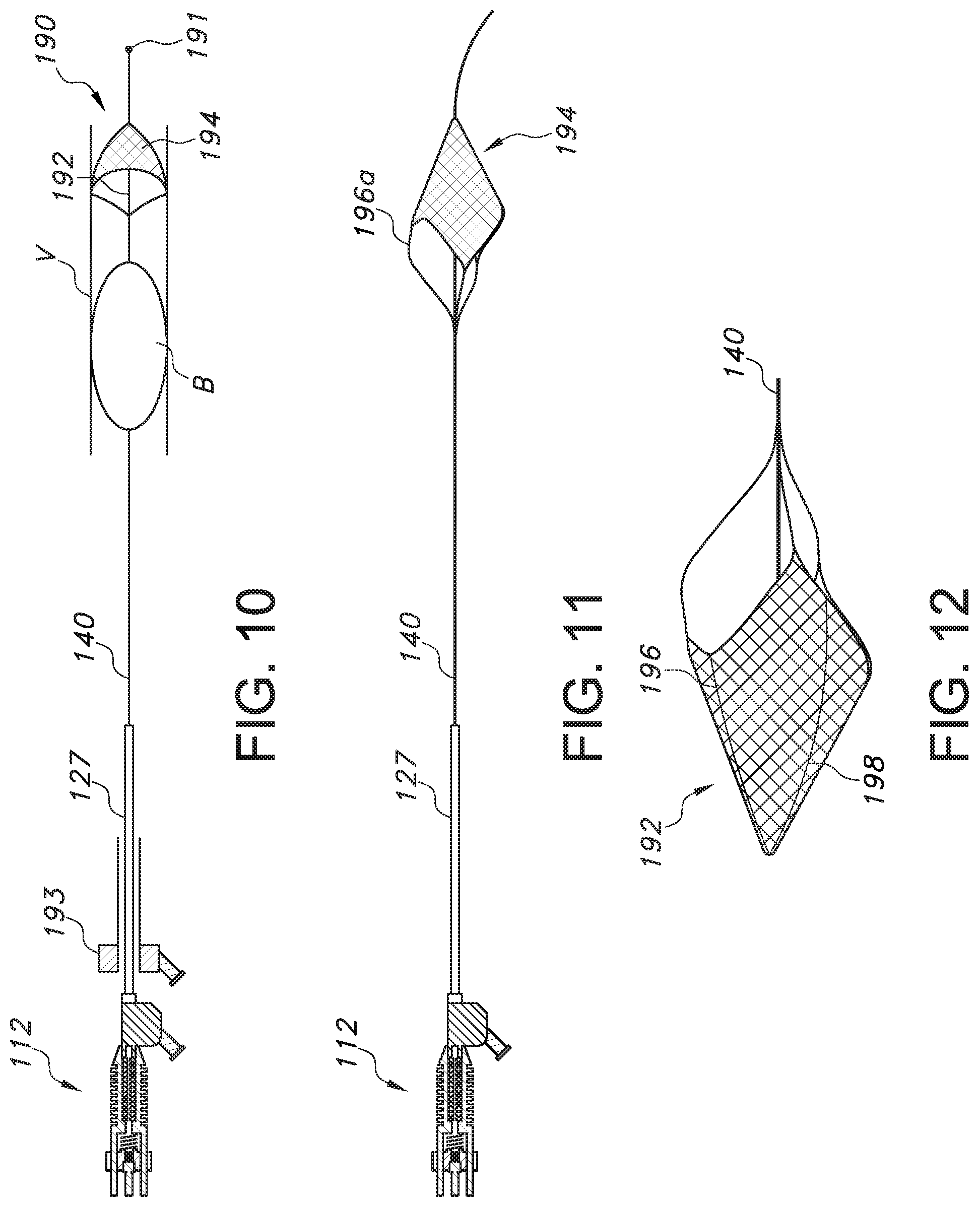
Turning now to FIGS. 10, 11 and 12, it can also be appreciated that a distal end of the wave guide 140 may be provided with a filter 190, which may be initially collapsed for passing through a thrombus B in a vessel V via a soft tip 191. In the illustrated embodiment, the filter 190 when expanded (such as by using a shape memory material) includes an open proximal end 12 and a body 194 comprising a filtering material, such as a fine mesh, cage, or the like. Thus, when the wave guide 140 is ultrasonically vibrated, any particles loosened from the obstruction (e.g., thrombus B) as a result may travel distally through the open end of the filter 190 and be captured by the body 194 for later removal once the procedure is completed. To remove any captured particles or objects, the filter 190 may be collapsed, such as using an external sheath 193 (which may also provide suction via a provided port to withdraw any dislodged material).
FIGS. 11 and 12 illustrate a specific example of a filter 190, which may comprise a body 194 including an expandable frame 196 (again, using a shape memory material) supporting a flexible or foldable material 198, such as a fabric, film (such as, for example, a porous polymer film), or the like. The frame 196 when expanded may form a conical structure having an open proximal end 192 oriented similarly as in FIG. 10 and a closed distal end. The material 198 connected to the frame forms a basket for capturing dislodged particles created from the vibration of the wave guide 140. As illustrated, the filter 190 may be connected to the wave guide 140 by tethers 196a, which may also form part of the frame 196, and thus the wave guide may also transmit vibratory energy to the filter 190. To remove any captured particles or objects, the filter 190 may be collapsed, such as by using temperature control to return the shape memory material to its original state during insertion.
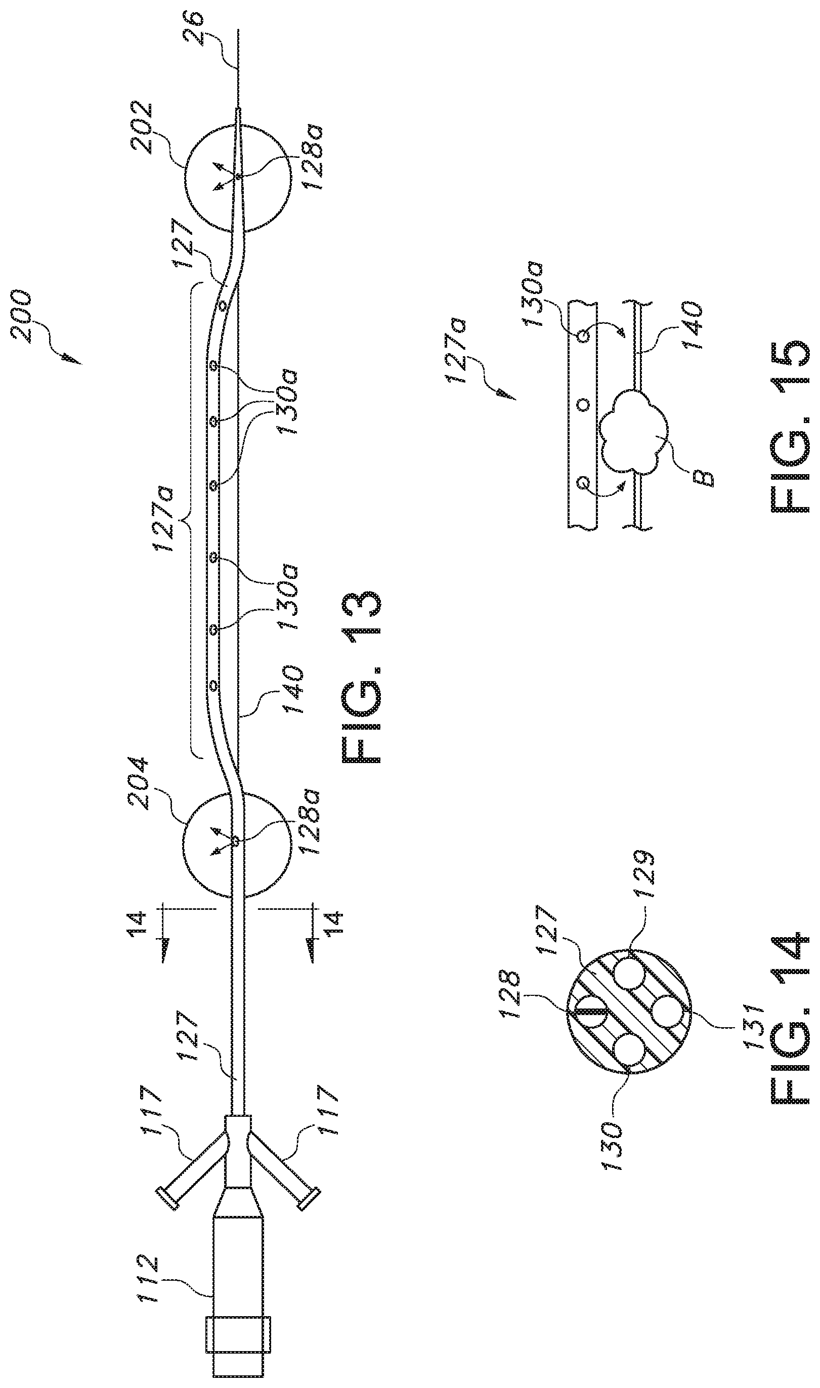
A further embodiment of an ultrasonic catheter 200 is illustrated with reference to FIGS. 13 and 14. In this embodiment, the catheter body 127 supports a plurality of inflatable balloons. Specifically, a first balloon 202 is positioned adjacent a distal end of the body 127, and a second balloon 204 is positioned proximally of the first balloon. The balloons 202, 204 may be inflated via a dual or coaxial inflation lumen 128 provided in the catheter body 127, which may include inlets 128a located in and communicating with the interior compartment of each balloon. Lumen 128 may receive inflation fluid from the fluid inlet port 117. When inflated, the balloons 202, 204 thus serve to anchor the catheter 200 at a treatment site, and also isolate a portion of the site for undergoing treatment.
The catheter body 127 may also include a second lumen 129 for receiving the wave guide 140. This second lumen 129 allows for an exposed portion to exit and pass external to the body 127 along a distal portion thereof, and ultimately re-enter the body at a point distal of the exit point, but proximal of the first distal balloon 202. To avoid interfering with the ultrasonic vibration of the wave guide 140, a corresponding portion 127a of the catheter body 127 may be non-linear or curved, and thus spaced from the wave guide 140, but could optionally be straight or partially curved.
A third lumen 130 in the body 127 may communicate with openings 130a in the portion 127a of the catheter body 127 intermediate the balloons 202, 204. These openings 130a may be used to withdraw fluid from a vessel when the body 127 is inserted therein, such as through a fluid port 118 associated with the connector 112. Alternatively, the openings 130a via lumen 130 or may be used to deliver substances to the vessel, such as, for instance, thrombolytic agents (such as, for example, Eminase (anistreplase) Retavase (reteplase) Streptase (streptokinase, kabikinase) t-PA (class of drugs that includes Activase) TNKase (tenecteplase) Abbokinase, Kinlytic (rokinase), or others). The body 127 may also optionally include a guidewire lumen 131 for receiving a guidewire 13, but use of a rapid-exchange configuration as described above is also possible.
In use, the wave guide 140 as a result of the advancement of the catheter body 127 may pass through or adjacent the obstruction in a vessel, such as thrombus B. The balloons 202, 204 may be inflated in the vessel being treated to concurrently anchor the catheter 200, which as can be appreciated serves to isolate a portion of the vessel including the obstruction (thrombus B). Substances such as thrombolytic agents may then be optionally delivered to the isolated portion of the vessel under treatment via port 118, lumen 130, and openings 130a to aid in dissolving the obstruction, and concurrently (or not), the wave guide 140 may be used to deliver ultrasonic energy to further assist in clearing the obstruction.
With the balloons 202, 204 remaining inflated, it can also be appreciated that the openings 130a may be used to remove material (including fluid) from the isolated portion of the vessel, such as by applying appropriate suction to the port 118. This may be done after a suitable amount of time has passed to ensure that any agents introduced have had time to act on the obstruction. When the obstruction is reduced or removed, the balloons 202, 204 may be deflated and the catheter body 127 moved along guidewire 13 as desired for removal or further treatment at an alternate location.
A further embodiment of an ultrasonic catheter 300 is shown in FIGS. 16 and 17, which includes a catheter body 127. In FIG. 16, the wave guide 140 comprises a tube 302, rather than a solid wire. This tube 302 which may be used to transmit ultrasonic energy from a transducer 14 to an obstruction, such as thrombus B (or thrombi). The distal end 302a of the tube 302 serving as wave guide 140 may be capped by an atraumatic tip 304, which may be used to move the tube 302 through the thrombus B (or thrombi). The tip 304 may also include a guidewire lumen 304a for guiding the tube 302 along a guide wire (not shown), which may be associated with a lumen in the catheter body 127 (see, e.g., FIG. 14).
In one particular embodiment, the tube 302 is adapted to inflate a balloon 306. The balloon 306 may be supported on the tube 302 proximally of the tip 304. The inflation fluid for inflating the balloon 306 may flow through the tube 302 via a proximal port (not shown). The fluid may exit the tube 302 to the interior compartment of the balloon via a port 302b.
In use, the catheter 300 may be partially passed through the obstruction (thrombus or thrombi) using tip 304 to extend the tube 302 therethrough, and the balloon 306 inflated. The transducer 14 may be activated to transmit energy to the obstruction to disrupt or dislodge it, with any dislodged particles or material being aspirated through the catheter body 127 (see arrows A). Additionally or alternatively, any thrombolytic agents may be delivered via the catheter body 127 to the treatment site prior to or during the tube activation to facilitate dissolving the obstruction, with any such substances remaining at the introduction site in view of the distal blockage created when the balloon 306 is inflated. When the procedure is complete, the balloon 306 may be deflated using the port 302b, and the catheter 300 moved accordingly.
FIG. 17 further illustrates that a second, proximal balloon 308 may also be provided on the ultrasonic catheter 300, which may likewise be inflated using a port 302c in tube 302 (such as using a coaxial or dual lumen). The balloons 306, 308 may thus be inflated on either side of the obstruction to isolate it. Wave guide 140 may be activated as desired to disrupt the obstruction. Ports or openings 302d may also be provided in the tube 302 for aspirating debris or introducing treatment agents, with corresponding lumens (not shown) provided in the tube as necessary for this purpose (see, e.g., multi-lumen catheter body 127 in FIG. 14). Alternatively, once the obstruction is cleared, the proximal balloon 308 may be deflated and the body 127 used to aspirate any dislodged material.
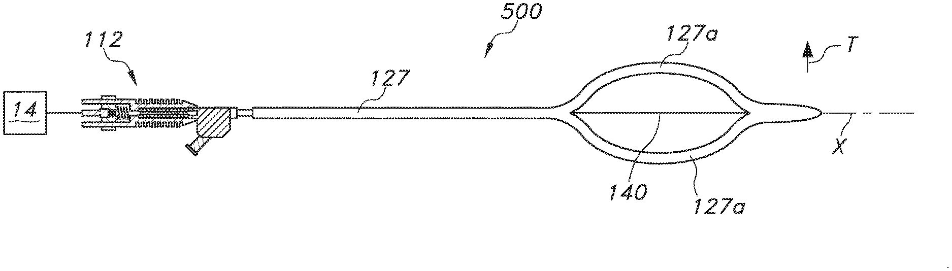
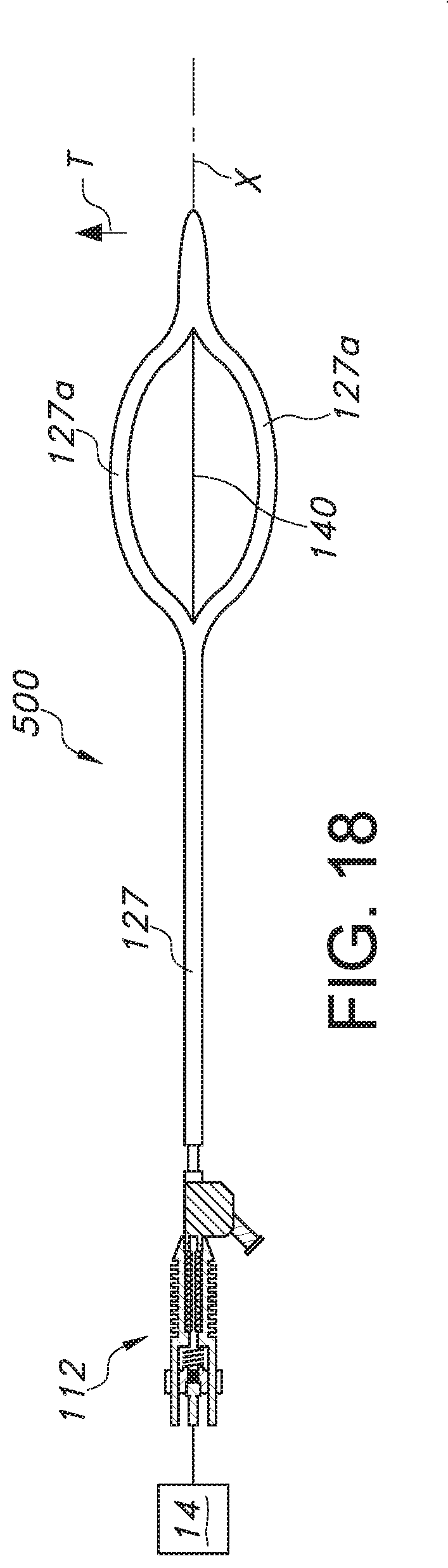
Turning now to FIG. 18, a further embodiment of an ultrasonic catheter 500 is shown. In this embodiment, the catheter body 127 may include one or more curved portions, such as two curved portions 127a, that are spaced in a transverse direction T from the wave guide 140. In the illustrated embodiment, the portions 127a are symmetrical about the longitudinal axis X and curved in opposition to each other (relative to a central longitudinal axis of the catheter). These portions 127 thus provide a centering function for the wave guide 140, which may be exposed in a space between the portions 127a for transmitting ultrasonic energy from an associated transducer 14 to a treatment site. The wave guide 140 may also extend to and possibly through a distal tip of the catheter body 127, and may be connected to it.
In summary, improved ultrasonic catheters 110, 200, 300, 500 are disclosed. In one example, the catheter 110 includes a wave guide 140 for transmitting ultrasonic energy from a transducer 14, and which is also rotated by a motor 154 to facilitate enhanced disruption of the concerned obstruction in a transverse direction. Embodiments of waveguide 140 include distal anchors 180 to restrain a corresponding portion of the waveguide, and may also include a deployable filter 190 that may open distal of the obstruction to capture any dislodged debris (which may be aspirated by the catheter body 127, including by advancing it). An embodiment of an ultrasonic catheter 200 is also disclosed that includes selectively inflatable balloons 206, 208 to cordon off a treatment site, as well as an embodiment in which the waveguide 104 comprises a tube 302 that may serve the dual purposes of inflating an associated balloon 306 (or balloons 306, 308), as well as to transmit ultrasonic energy to an obstruction. Still a further embodiment of a catheter 500 comprises a plurality of curved portions 127a spaced from a wave guide 140.
The foregoing description has been presented for purposes of illustration. It is not intended to be exhaustive or to limit the embodiments to the precise form disclosed. Obvious modifications and variations are possible in light of the above teachings. All modifications and variations are within the scope of the appended claims when interpreted in accordance with the breadth to which they are fairly, legally and equitably entitled.
* * * * *
References
D00000
D00001
D00002
D00003
D00004
D00005
D00006
D00007
D00008
XML
uspto.report is an independent third-party trademark research tool that is not affiliated, endorsed, or sponsored by the United States Patent and Trademark Office (USPTO) or any other governmental organization. The information provided by uspto.report is based on publicly available data at the time of writing and is intended for informational purposes only.
While we strive to provide accurate and up-to-date information, we do not guarantee the accuracy, completeness, reliability, or suitability of the information displayed on this site. The use of this site is at your own risk. Any reliance you place on such information is therefore strictly at your own risk.
All official trademark data, including owner information, should be verified by visiting the official USPTO website at www.uspto.gov. This site is not intended to replace professional legal advice and should not be used as a substitute for consulting with a legal professional who is knowledgeable about trademark law.