Apparatus and methods for additive manufacturing with variable extruder profiles
Lakshman , et al. A
U.S. patent number 10,751,934 [Application Number 15/886,761] was granted by the patent office on 2020-08-25 for apparatus and methods for additive manufacturing with variable extruder profiles. This patent grant is currently assigned to DIVERGENT TECHNOLOGIES, INC.. The grantee listed for this patent is DIVERGENT TECHNOLOGIES, INC.. Invention is credited to Narender Shankar Lakshman, Broc William TenHouten.


View All Diagrams
| United States Patent | 10,751,934 |
| Lakshman , et al. | August 25, 2020 |
Apparatus and methods for additive manufacturing with variable extruder profiles
Abstract
Apparatus and methods for additive manufacturing with variable extruder profiles are described herein. An extruder print head with multiple nozzles placed at different angles allows for additional degrees of freedom to additively manufacture parts with complex shapes. In addition with the use of shape memory alloy materials, the diameter of one or more nozzles can be adjusted during the additive manufacturing process. This allows for independent control of the build resolution and of the build rate.
| Inventors: | Lakshman; Narender Shankar (Torrance, CA), TenHouten; Broc William (Rancho Palos Verdes, CA) | ||||||||||
|---|---|---|---|---|---|---|---|---|---|---|---|
| Applicant: |
|
||||||||||
| Assignee: | DIVERGENT TECHNOLOGIES, INC.
(Los Angeles, CA) |
||||||||||
| Family ID: | 67391766 | ||||||||||
| Appl. No.: | 15/886,761 | ||||||||||
| Filed: | February 1, 2018 |
Prior Publication Data
| Document Identifier | Publication Date | |
|---|---|---|
| US 20190232553 A1 | Aug 1, 2019 | |
| Current U.S. Class: | 1/1 |
| Current CPC Class: | B33Y 40/00 (20141201); B29C 64/20 (20170801); B29C 64/393 (20170801); B29C 64/118 (20170801); B29C 64/209 (20170801); B29C 64/112 (20170801); B33Y 10/00 (20141201); B29C 64/386 (20170801); B33Y 30/00 (20141201); B33Y 50/02 (20141201) |
| Current International Class: | B29C 45/16 (20060101); B29C 64/112 (20170101); B33Y 30/00 (20150101); B29C 64/20 (20170101); B33Y 10/00 (20150101); B29C 64/386 (20170101); B33Y 40/00 (20200101); B29C 64/393 (20170101); B29C 64/209 (20170101); B29C 64/118 (20170101); B33Y 50/02 (20150101) |
| Field of Search: | ;700/118 |
References Cited [Referenced By]
U.S. Patent Documents
| 5203226 | April 1993 | Hongou et al. |
| 5742385 | April 1998 | Champa |
| 5990444 | November 1999 | Costin |
| 6010155 | January 2000 | Rinehart |
| 6096249 | August 2000 | Yamaguchi |
| 6140602 | October 2000 | Costin |
| 6250533 | June 2001 | Otterbein et al. |
| 6252196 | June 2001 | Costin et al. |
| 6318642 | November 2001 | Goenka et al. |
| 6365057 | April 2002 | Whitehurst et al. |
| 6391251 | May 2002 | Keicher et al. |
| 6409930 | June 2002 | Whitehurst et al. |
| 6468439 | October 2002 | Whitehurst et al. |
| 6554345 | April 2003 | Jonsson |
| 6585151 | July 2003 | Ghosh |
| 6644721 | November 2003 | Miskech et al. |
| 6811744 | November 2004 | Keicher et al. |
| 6866497 | March 2005 | Saiki |
| 6919035 | July 2005 | Clough |
| 6926970 | August 2005 | James et al. |
| 7152292 | December 2006 | Hohmann et al. |
| 7344186 | March 2008 | Hausler et al. |
| 7500373 | March 2009 | Quell |
| 7586062 | September 2009 | Heberer |
| 7637134 | December 2009 | Burzlaff et al. |
| 7710347 | May 2010 | Gentilman et al. |
| 7716802 | May 2010 | Stern et al. |
| 7745293 | June 2010 | Yamazaki et al. |
| 7766123 | August 2010 | Sakurai et al. |
| 7852388 | December 2010 | Shimizu et al. |
| 7908922 | March 2011 | Zarabadi et al. |
| 7951324 | May 2011 | Naruse et al. |
| 8094036 | January 2012 | Heberer |
| 8163077 | April 2012 | Eron et al. |
| 8286236 | October 2012 | Jung et al. |
| 8289352 | October 2012 | Vartanian et al. |
| 8297096 | October 2012 | Mizumura et al. |
| 8354170 | January 2013 | Henry et al. |
| 8383028 | February 2013 | Lyons |
| 8408036 | April 2013 | Reith et al. |
| 8429754 | April 2013 | Jung et al. |
| 8437513 | May 2013 | Derakhshani et al. |
| 8444903 | May 2013 | Lyons et al. |
| 8452073 | May 2013 | Taminger et al. |
| 8599301 | December 2013 | Dowski, Jr. et al. |
| 8606540 | December 2013 | Haisty et al. |
| 8610761 | December 2013 | Haisty et al. |
| 8631996 | January 2014 | Quell et al. |
| 8675925 | March 2014 | Derakhshani et al. |
| 8678060 | March 2014 | Dietz et al. |
| 8686314 | April 2014 | Schneegans et al. |
| 8686997 | April 2014 | Radet et al. |
| 8694284 | April 2014 | Berard |
| 8720876 | May 2014 | Reith et al. |
| 8752166 | June 2014 | Jung et al. |
| 8755923 | June 2014 | Farahani et al. |
| 8787628 | July 2014 | Derakhshani et al. |
| 8818771 | August 2014 | Gielis et al. |
| 8873238 | October 2014 | Wilkins |
| 8978535 | March 2015 | Ortiz et al. |
| 9006605 | April 2015 | Schneegans et al. |
| 9071436 | June 2015 | Jung et al. |
| 9101979 | August 2015 | Hofmann et al. |
| 9104921 | August 2015 | Derakhshani et al. |
| 9126365 | September 2015 | Mark et al. |
| 9128476 | September 2015 | Jung et al. |
| 9138924 | September 2015 | Yen |
| 9149988 | October 2015 | Mark et al. |
| 9156205 | October 2015 | Mark et al. |
| 9186848 | November 2015 | Mark et al. |
| 9244986 | January 2016 | Karmarkar |
| 9248611 | February 2016 | Divine et al. |
| 9254535 | February 2016 | Buller et al. |
| 9266566 | February 2016 | Kim |
| 9269022 | February 2016 | Rhoads et al. |
| 9327452 | May 2016 | Mark et al. |
| 9329020 | May 2016 | Napoletano |
| 9332251 | May 2016 | Haisty et al. |
| 9346127 | May 2016 | Buller et al. |
| 9389315 | July 2016 | Bruder et al. |
| 9399256 | July 2016 | Buller et al. |
| 9403235 | August 2016 | Buller et al. |
| 9418193 | August 2016 | Dowski, Jr. et al. |
| 9457514 | October 2016 | Schwarzler |
| 9469057 | October 2016 | Johnson et al. |
| 9478063 | October 2016 | Rhoads et al. |
| 9481402 | November 2016 | Muto et al. |
| 9486878 | November 2016 | Buller et al. |
| 9486960 | November 2016 | Paschkewitz et al. |
| 9502993 | November 2016 | Deng |
| 9522522 | December 2016 | Bredt |
| 9525262 | December 2016 | Stuart et al. |
| 9533526 | January 2017 | Nevins |
| 9555315 | January 2017 | Aders |
| 9555580 | January 2017 | Dykstra et al. |
| 9557856 | January 2017 | Send et al. |
| 9566742 | February 2017 | Keating et al. |
| 9566758 | February 2017 | Cheung et al. |
| 9573193 | February 2017 | Buller et al. |
| 9573225 | February 2017 | Buller et al. |
| 9586290 | March 2017 | Buller et al. |
| 9595795 | March 2017 | Lane et al. |
| 9597843 | March 2017 | Stauffer et al. |
| 9600929 | March 2017 | Young et al. |
| 9609755 | March 2017 | Coull et al. |
| 9610737 | April 2017 | Johnson et al. |
| 9611667 | April 2017 | GangaRao et al. |
| 9616623 | April 2017 | Johnson et al. |
| 9626487 | April 2017 | Jung et al. |
| 9626489 | April 2017 | Nilsson |
| 9643361 | May 2017 | Liu |
| 9662840 | May 2017 | Buller et al. |
| 9665182 | May 2017 | Send et al. |
| 9669586 | June 2017 | Page |
| 9672389 | June 2017 | Mosterman et al. |
| 9672550 | June 2017 | Apsley et al. |
| 9676145 | June 2017 | Buller et al. |
| 9684919 | June 2017 | Apsley et al. |
| 9688032 | June 2017 | Kia et al. |
| 9690286 | June 2017 | Hovsepian et al. |
| 9700966 | July 2017 | Kraft et al. |
| 9703896 | July 2017 | Zhang et al. |
| 9713903 | July 2017 | Paschkewitz et al. |
| 9718302 | August 2017 | Young et al. |
| 9718434 | August 2017 | Hector, Jr. et al. |
| 9724877 | August 2017 | Flitsch et al. |
| 9724881 | August 2017 | Johnson et al. |
| 9725178 | August 2017 | Wang |
| 9731730 | August 2017 | Stiles |
| 9731773 | August 2017 | Gami et al. |
| 9741954 | August 2017 | Bruder et al. |
| 9747352 | August 2017 | Karmarkar |
| 9764415 | September 2017 | Seufzer et al. |
| 9764520 | September 2017 | Johnson et al. |
| 9765226 | September 2017 | Dain |
| 9770760 | September 2017 | Liu |
| 9773393 | September 2017 | Velez |
| 9776234 | October 2017 | Schaafhausen et al. |
| 9782936 | October 2017 | Glunz et al. |
| 9783324 | October 2017 | Embler et al. |
| 9783977 | October 2017 | Alqasimi et al. |
| 9789548 | October 2017 | Golshany et al. |
| 9789922 | October 2017 | Dosenbach et al. |
| 9796137 | October 2017 | Zhang et al. |
| 9802108 | October 2017 | Aders |
| 9809977 | November 2017 | Carney et al. |
| 9817922 | November 2017 | Glunz et al. |
| 9818071 | November 2017 | Jung et al. |
| 9821339 | November 2017 | Paschkewitz et al. |
| 9821411 | November 2017 | Buller et al. |
| 9823143 | November 2017 | Twelves, Jr. et al. |
| 9829564 | November 2017 | Bruder et al. |
| 9846933 | December 2017 | Yuksel |
| 9854828 | January 2018 | Langeland |
| 9858604 | January 2018 | Apsley et al. |
| 9862833 | January 2018 | Hasegawa et al. |
| 9862834 | January 2018 | Hasegawa et al. |
| 9863885 | January 2018 | Zaretski et al. |
| 9870629 | January 2018 | Cardno et al. |
| 9879981 | January 2018 | Dehghan Niri et al. |
| 9884663 | February 2018 | Czinger et al. |
| 9898776 | February 2018 | Apsley et al. |
| 9914150 | March 2018 | Pettersson et al. |
| 9919360 | March 2018 | Buller et al. |
| 9931697 | April 2018 | Levin et al. |
| 9933031 | April 2018 | Bracamonte et al. |
| 9933092 | April 2018 | Sindelar |
| 9957031 | May 2018 | Golshany et al. |
| 9958535 | May 2018 | Send et al. |
| 9962767 | May 2018 | Buller et al. |
| 9963978 | May 2018 | Johnson et al. |
| 9971920 | May 2018 | Derakhshani et al. |
| 9976063 | May 2018 | Childers et al. |
| 9987792 | June 2018 | Flitsch et al. |
| 9988136 | June 2018 | Tiryaki et al. |
| 9989623 | June 2018 | Send et al. |
| 9990565 | June 2018 | Rhoads et al. |
| 9994339 | June 2018 | Colson et al. |
| 9996890 | June 2018 | Cinnamon et al. |
| 9996945 | June 2018 | Holzer et al. |
| 10002215 | June 2018 | Dowski et al. |
| 10006156 | June 2018 | Kirkpatrick |
| 10011089 | July 2018 | Lyons et al. |
| 10011685 | July 2018 | Childers et al. |
| 10012532 | July 2018 | Send et al. |
| 10013777 | July 2018 | Mariampillai et al. |
| 10015908 | July 2018 | Williams et al. |
| 10016852 | July 2018 | Broda |
| 10016942 | July 2018 | Mark et al. |
| 10017384 | July 2018 | Greer et al. |
| 10018576 | July 2018 | Herbsommer et al. |
| 10022792 | July 2018 | Srivas et al. |
| 10022912 | July 2018 | Kia et al. |
| 10027376 | July 2018 | Sankaran et al. |
| 10029415 | July 2018 | Swanson et al. |
| 10040239 | August 2018 | Brown, Jr. |
| 10046412 | August 2018 | Blackmore |
| 10048769 | August 2018 | Selker et al. |
| 10052712 | August 2018 | Blackmore |
| 10052820 | August 2018 | Kemmer et al. |
| 10055536 | August 2018 | Maes et al. |
| 10058764 | August 2018 | Aders |
| 10058920 | August 2018 | Buller et al. |
| 10061906 | August 2018 | Nilsson |
| 10065270 | September 2018 | Buller et al. |
| 10065361 | September 2018 | Susnjara et al. |
| 10065367 | September 2018 | Brown, Jr. |
| 10068316 | September 2018 | Holzer et al. |
| 10071422 | September 2018 | Buller et al. |
| 10071525 | September 2018 | Susnjara et al. |
| 10072179 | September 2018 | Drijfhout |
| 10074128 | September 2018 | Colson et al. |
| 10076875 | September 2018 | Mark et al. |
| 10076876 | September 2018 | Mark et al. |
| 10081140 | September 2018 | Paesano et al. |
| 10081431 | September 2018 | Seack et al. |
| 10086568 | October 2018 | Snyder et al. |
| 10087320 | October 2018 | Simmons et al. |
| 10087556 | October 2018 | Gallucci et al. |
| 10099427 | October 2018 | Mark et al. |
| 10100542 | October 2018 | GangaRao et al. |
| 10100890 | October 2018 | Bracamonte et al. |
| 10107344 | October 2018 | Bracamonte et al. |
| 10108766 | October 2018 | Druckman et al. |
| 10113600 | October 2018 | Bracamonte et al. |
| 10118347 | November 2018 | Stauffer et al. |
| 10118579 | November 2018 | Lakic |
| 10120078 | November 2018 | Bruder et al. |
| 10124546 | November 2018 | Johnson et al. |
| 10124570 | November 2018 | Evans et al. |
| 10137500 | November 2018 | Blackmore |
| 10138354 | November 2018 | Groos et al. |
| 10144126 | December 2018 | Krohne et al. |
| 10145110 | December 2018 | Carney et al. |
| 10151363 | December 2018 | Bracamonte et al. |
| 10152661 | December 2018 | Kieser |
| 10160278 | December 2018 | Coombs et al. |
| 10161021 | December 2018 | Lin et al. |
| 10166752 | January 2019 | Evans et al. |
| 10166753 | January 2019 | Evans et al. |
| 10171578 | January 2019 | Cook et al. |
| 10173255 | January 2019 | TenHouten et al. |
| 10173327 | January 2019 | Kraft et al. |
| 10178800 | January 2019 | Mahalingam et al. |
| 10179640 | January 2019 | Wilkerson |
| 10183330 | January 2019 | Buller et al. |
| 10183478 | January 2019 | Evans et al. |
| 10189187 | January 2019 | Keating et al. |
| 10189240 | January 2019 | Evans et al. |
| 10189241 | January 2019 | Evans et al. |
| 10189242 | January 2019 | Evans et al. |
| 10190424 | January 2019 | Johnson et al. |
| 10195693 | February 2019 | Buller et al. |
| 10196539 | February 2019 | Boonen et al. |
| 10197338 | February 2019 | Melsheimer |
| 10200677 | February 2019 | Trevor et al. |
| 10201932 | February 2019 | Flitsch et al. |
| 10201941 | February 2019 | Evans et al. |
| 10202673 | February 2019 | Lin et al. |
| 10204216 | February 2019 | Nejati et al. |
| 10207454 | February 2019 | Buller et al. |
| 10209065 | February 2019 | Estevo, Jr. et al. |
| 10210662 | February 2019 | Holzer et al. |
| 10213837 | February 2019 | Kondoh |
| 10214248 | February 2019 | Hall et al. |
| 10214252 | February 2019 | Schellekens et al. |
| 10214275 | February 2019 | Goehlich |
| 10220575 | March 2019 | Reznar |
| 10220881 | March 2019 | Tyan et al. |
| 10221530 | March 2019 | Driskell et al. |
| 10226900 | March 2019 | Nevins |
| 10232550 | March 2019 | Evans et al. |
| 10234342 | March 2019 | Moorlag et al. |
| 10237477 | March 2019 | Trevor et al. |
| 10252335 | April 2019 | Buller et al. |
| 10252336 | April 2019 | Buller et al. |
| 10254499 | April 2019 | Cohen |
| 10257499 | April 2019 | Hintz et al. |
| 10259044 | April 2019 | Buller et al. |
| 10268181 | April 2019 | Nevins |
| 10269225 | April 2019 | Velez |
| 10272860 | April 2019 | Mohapatra et al. |
| 10272862 | April 2019 | Whitehead |
| 10275564 | April 2019 | Ridgeway et al. |
| 10279580 | May 2019 | Evans et al. |
| 10285219 | May 2019 | Feffatsidis et al. |
| 10286452 | May 2019 | Buller et al. |
| 10286603 | May 2019 | Buller et al. |
| 10286961 | May 2019 | Hillebrecht et al. |
| 10289263 | May 2019 | Troy et al. |
| 10289875 | May 2019 | Singh et al. |
| 10291193 | May 2019 | Dandu et al. |
| 10294552 | May 2019 | Liu et al. |
| 10294982 | May 2019 | Gabrys et al. |
| 10295989 | May 2019 | Nevins |
| 10303159 | May 2019 | Czinger et al. |
| 10307824 | June 2019 | Kondoh |
| 10310197 | June 2019 | Droz et al. |
| 10313651 | June 2019 | Trevor et al. |
| 10315252 | June 2019 | Mendelsberg et al. |
| 10336050 | July 2019 | Susnjara |
| 10337542 | July 2019 | Hesslewood et al. |
| 10337952 | July 2019 | Bosetti et al. |
| 10339266 | July 2019 | Urick et al. |
| 10343330 | July 2019 | Evans et al. |
| 10343331 | July 2019 | McCall et al. |
| 10343355 | July 2019 | Evans et al. |
| 10343724 | July 2019 | Polewarczyk et al. |
| 10343725 | July 2019 | Martin et al. |
| 10350823 | July 2019 | Rolland et al. |
| 10356341 | July 2019 | Holzer et al. |
| 10356395 | July 2019 | Holzer et al. |
| 10357829 | July 2019 | Spink et al. |
| 10357957 | July 2019 | Buller et al. |
| 10359756 | July 2019 | Newell et al. |
| 10369629 | August 2019 | Mendelsberg et al. |
| 10382739 | August 2019 | Rusu et al. |
| 10384393 | August 2019 | Xu et al. |
| 10384416 | August 2019 | Cheung et al. |
| 10389410 | August 2019 | Brooks et al. |
| 10391710 | August 2019 | Mondesir |
| 10392097 | August 2019 | Pham et al. |
| 10392131 | August 2019 | Deck et al. |
| 10393315 | August 2019 | Tyan |
| 10400080 | September 2019 | Ramakrishnan et al. |
| 10401832 | September 2019 | Snyder et al. |
| 10403009 | September 2019 | Mariampillai et al. |
| 10406750 | September 2019 | Barton et al. |
| 10412283 | September 2019 | Send et al. |
| 10416095 | September 2019 | Herbsommer et al. |
| 10421496 | September 2019 | Swayne et al. |
| 10421863 | September 2019 | Hasegawa et al. |
| 10422478 | September 2019 | Leachman et al. |
| 10425793 | September 2019 | Sankaran et al. |
| 10427364 | October 2019 | Alves |
| 10429006 | October 2019 | Tyan et al. |
| 10434573 | October 2019 | Buller et al. |
| 10435185 | October 2019 | Divine et al. |
| 10435773 | October 2019 | Liu et al. |
| 10436038 | October 2019 | Buhler et al. |
| 10438407 | October 2019 | Pavanaskar et al. |
| 10440351 | October 2019 | Holzer et al. |
| 10442002 | October 2019 | Benthien et al. |
| 10442003 | October 2019 | Symeonidis et al. |
| 10449696 | October 2019 | Elgar et al. |
| 10449737 | October 2019 | Johnson et al. |
| 10461810 | October 2019 | Cook et al. |
| 2006/0108783 | May 2006 | Ni et al. |
| 2013/0296812 | November 2013 | Bangera |
| 2014/0061974 | March 2014 | Tyler |
| 2014/0277669 | September 2014 | Nardi et al. |
| 2014/0291886 | October 2014 | Mark et al. |
| 2016/0271367 | September 2016 | Hyde et al. |
| 2017/0113344 | April 2017 | Schonberg |
| 2017/0157844 | June 2017 | Mandel |
| 2017/0165917 | June 2017 | McKiel, Jr. |
| 2017/0173692 | June 2017 | Myerberg |
| 2017/0173884 | June 2017 | Ryan |
| 2017/0182701 | June 2017 | Ryan et al. |
| 2017/0341309 | November 2017 | Piepenbrock et al. |
| 2018/0154573 | June 2018 | Miles |
| 2018/0243980 | August 2018 | Erb |
| 2018/0319079 | November 2018 | Eyal |
| 3117982 | Jan 2017 | EP | |||
| 1996036455 | Nov 1996 | WO | |||
| 1996036525 | Nov 1996 | WO | |||
| 1996038260 | Dec 1996 | WO | |||
| 2003024641 | Mar 2003 | WO | |||
| 2004108343 | Dec 2004 | WO | |||
| 2005093773 | Oct 2005 | WO | |||
| 2007003375 | Jan 2007 | WO | |||
| 2007110235 | Oct 2007 | WO | |||
| 2007110236 | Oct 2007 | WO | |||
| 2008019847 | Feb 2008 | WO | |||
| 2007128586 | Jun 2008 | WO | |||
| 2008068314 | Jun 2008 | WO | |||
| 2008086994 | Jul 2008 | WO | |||
| 2008087024 | Jul 2008 | WO | |||
| 2008107130 | Sep 2008 | WO | |||
| 2008138503 | Nov 2008 | WO | |||
| 2008145396 | Dec 2008 | WO | |||
| 2009083609 | Jul 2009 | WO | |||
| 2009098285 | Aug 2009 | WO | |||
| 2009112520 | Sep 2009 | WO | |||
| 2009135938 | Nov 2009 | WO | |||
| 2009140977 | Nov 2009 | WO | |||
| 2010125057 | Nov 2010 | WO | |||
| 2010125058 | Nov 2010 | WO | |||
| 2010142703 | Dec 2010 | WO | |||
| 2011032533 | Mar 2011 | WO | |||
| 2014016437 | Jan 2014 | WO | |||
| 2014187720 | Nov 2014 | WO | |||
| 2014195340 | Dec 2014 | WO | |||
| 2015193331 | Dec 2015 | WO | |||
| 2016116414 | Jul 2016 | WO | |||
| 2017036461 | Mar 2017 | WO | |||
| 2019030248 | Feb 2019 | WO | |||
| 2019042504 | Mar 2019 | WO | |||
| 2019048010 | Mar 2019 | WO | |||
| 2019048498 | Mar 2019 | WO | |||
| 2019048680 | Mar 2019 | WO | |||
| 2019048682 | Mar 2019 | WO | |||
Other References
|
US 9,202,136 B2, 12/2015, Schmidt et al. (withdrawn) cited by applicant . US 9,809,265 B2, 11/2017, Kinjo (withdrawn) cited by applicant . US 10,449,880 B2, 10/2019, Mizobata et al. (withdrawn) cited by applicant . International Search Report and Written Opinion dated Mar. 28, 2019 regarding PCT/US2018/065000. cited by applicant. |
Primary Examiner: Suryawanshi; Suresh
Attorney, Agent or Firm: Arent Fox LLP
Claims
What is claimed is:
1. An additive manufacturing (AM) apparatus, comprising: a print material source; and a three-dimensional (3-D) print applicator comprising a plurality of nozzles, each nozzle positioned at a different angle with respect to a first axis, the plurality of nozzles being configured to receive print material from the print material source and to deposit sequential layers of the print material onto a build plate to produce an AM component.
2. The apparatus of claim 1, wherein at least one of the plurality of nozzles is additively manufactured.
3. The apparatus of claim 1, wherein a nozzle opening profile of at least one of the plurality of nozzles is configured to vary responsive to instructions from a controller linked to a 3-D printer.
4. The apparatus of claim 3, wherein the nozzle opening profile comprises a nozzle opening diameter.
5. The apparatus of claim 3, wherein the nozzle opening profile is configured in response to controller instructions to increase a size of the nozzle opening profile to reduce rendering time for the AM component.
6. The apparatus of claim 3, wherein the nozzle opening profile comprises a plurality of sizes; and the nozzle opening profile is configured in response to controller instructions to reduce its size to a value correlative to one or more features of the AM component.
7. The apparatus of claim 6, wherein a reduction in size of the nozzle opening profile increases a rendering accuracy of the one or more features.
8. The apparatus of claim 1, wherein the 3-D print applicator comprises a surface on which the plurality of nozzles is arranged, and the surface is curved.
9. The apparatus of claim 8, wherein the curved surface comprises at least a concave curved surface or a convex curved surface.
10. The apparatus of claim 8, wherein the plurality of nozzles arranged on the curved surface is configured to deposit the print material at different angles relative to the build plate.
11. The apparatus of claim 1, wherein the plurality of nozzles comprises a first removable nozzle having a first profile.
12. The apparatus of claim 11, further comprising a mechanical assembly coupled to the 3-D print applicator and further including: a sensor in communication with a controller for receiving instructions; and an actuator coupled to the 3-D print applicator and configured to replace, responsive to an indication from the sensor based on the received instructions, the first removable nozzle with a second removable nozzle having a second profile.
13. A method of additive manufacturing comprising: providing a print material source; receiving, at a three-dimensional (3-D) print applicator comprising a plurality of nozzles wherein each nozzle is positioned at a different angle with respect to a first axis, print material from the print material source; and depositing, by at least one nozzle associated with the 3-D print applicator, sequential layers of the print material to thereby form a 3-D printed object.
14. The method of claim 13, wherein a profile comprises a nozzle opening profile, the nozzle opening profile comprising a nozzle opening diameter.
15. The method of claim 14, further comprising automatedly selecting the nozzle opening profile to be small to accurately print small features.
16. The method of claim 15, wherein automatedly selecting the nozzle opening profile to be small comprises reducing the diameter.
17. The method of claim 14, further comprising automatedly selecting the nozzle opening profile to be larger to reduce rendering time for the 3-D printed object.
18. The method of claim 17, wherein automatedly selecting the nozzle opening profile to be larger comprises increasing the diameter.
19. The method of claim 14, wherein the profile comprises a nozzle curvature.
20. The method of claim 19, comprising automatedly selecting the profile to be one of concave curvature or convex curvature.
Description
BACKGROUND
Field
The present disclosure relates generally to three dimensional (3D) additive manufacturing, and more specifically to additive manufacturing with variable extruder profiles.
Background
The process of building layers of materials using a three dimensional (3D) printer is referred to as additive manufacturing (AM). A material extrusion printer is one type of 3D printer which additively manufactures solid objects on a print bed by extruding molten material through a nozzle.
A material extrusion printer is controlled by a computer which takes a 3D model of the solid object and translates it into printer control commands. In response to the control commands, the material extrusion printer feeds a filament of material, such as a thermoplastic, through an extruder head. The filament is forced into a heated nozzle where material is liquefied and extruded onto the print object. The extruder head and the print bed are moved in response to control commands so that the liquefied material can be deposited along specified coordinates to render the object.
SUMMARY
Several aspects of additively manufacturing with variable extruder profiles will be described more fully hereinafter with reference to material extrusion printers.
In one aspect an additive manufacturing (AM) apparatus comprises a print material source and a three-dimensional (3-D) print applicator. The three-dimensional print applicator comprises at least one nozzle; the at least one nozzle is configured to receive print material from the print material source and to deposit sequential layers of the print material onto a build plate to produce an AM component. A profile of the at least one nozzle is configured to vary responsive to instructions from a controller linked to the 3-D print applicator.
The at least one nozzle can be additively manufactured. The profile can comprise a nozzle opening profile, and the nozzle opening profile can comprise a diameter.
The nozzle opening profile can comprise a plurality of sizes, and the nozzle opening profile can be configured to reduce its size to a value correlative to one of more features of the AM component.
The reduction in size of the nozzle opening profile can increase a rendering accuracy of the one or more features. In response to controller instructions, the nozzle opening profile can be configured to increase its size to reduce rendering time for the AM component.
The 3-D print applicator can comprise a surface on which the at least one nozzle is arranged to deposit the print material onto the build plate; and the surface can be curved to extend outside a plane parallel to the at least one nozzle. The curved surface can comprise at least one of a concave or convex characteristic.
The at least one nozzle can comprise a plurality of nozzles arranged on the curved surface. The at least one nozzle can be configured to deposit the print material at different angles relative to the build plate.
The at least one nozzle can comprise a first removable nozzle having a first profile; and the apparatus can comprise a mechanical assembly coupled to the 3-D print applicator.
The apparatus can further include a sensor and an actuator. The sensor can be in communication with the controller for receiving instructions. The actuator can be coupled to the 3-D print applicator. Responsive to an indication from the sensor and based on the received instructions, the actuator can replace the first removable nozzle with a second removable nozzle having a second profile.
In another aspect a method of additive manufacturing comprises providing a print material source, receiving print material from the print material source, depositing sequential layers of the print material, and varying a profile of the at least one nozzle. Print material is received at a three-dimensional (3-D) print applicator. Sequential layers are deposited by at least one nozzle associated with the 3-D print applicator to thereby form a 3-D printed object. The profile of the at least one nozzle is varied in response to instructions from a controller linked to the 3-D print applicator.
The profile can comprise a nozzle opening profile; and the nozzle opening profile can comprise a diameter. The profile can comprise a nozzle curvature.
The method of additive manufacturing can further comprise automatedly selecting the nozzle opening profile to be small to accurately print small features. Automatedly selecting the nozzle opening profile to be small can comprise reducing the diameter.
The method of additive manufacturing can further comprise automatedly selecting the nozzle opening profile to be larger to reduce rendering time for the 3-D printed object. Automatedly selecting the nozzle opening profile to be larger can comprise increasing the diameter.
The method of additive manufacturing can further comprise automatedly selecting the profile to be one of concave or convex.
In another aspect an additive manufacturing (AM) apparatus comprises a print material source and a three-dimensional (3-D) print applicator. The three-dimensional print applicator may in an embodiment, but generally need not, comprise a closed loop actuator system. The closed loop actuator system comprises at least one nozzle and an actuator. The at least one nozzle is configured to receive print material from the print material source and to deposit sequential layers of the print material onto a build plate to produce an AM component.
The at least one nozzle can be additively manufactured. The at least one nozzle can comprise a nozzle opening profile; and the actuator can be a shape memory alloy actuator.
The closed loop actuator system can comprise a controller, and the controller can be configured to adjust the nozzle opening profile by controlling the shape memory alloy actuator. The nozzle opening profile can comprise a diameter of the at least one nozzle.
It will be understood that other aspects of additively manufacturing with variable extruder profiles will become readily apparent to those skilled in the art from the following detailed description, wherein it is shown and described only several embodiments by way of illustration. As will be appreciated by those skilled in the art, variable extruder profiles can be realized with other embodiments without departing from the invention. Accordingly, the drawings and detailed description are to be regarded as illustrative in nature and not as restrictive.
BRIEF DESCRIPTION OF THE DRAWINGS
Various aspects of apparatus and methods for additive manufacturing with variable extruder profiles will now be presented in the detailed description by way of example, and not by way of limitation, in the accompanying drawings, wherein:
FIG. 1A illustrates a material extrusion printer using a variable extruder head according to the teachings herein.
FIG. 1B illustrates another perspective of the material extrusion printer using a variable extruder head according to the teachings herein.
FIG. 2A illustrates a front view of the variable extruder head for printing a concave surface.
FIG. 2B illustrates a front view of the variable extruder head for printing a convex surface.
FIG. 3A illustrates a front view of a variable extruder head using more than one filament configured according to a first embodiment
FIG. 3B illustrates a front view of the variable extruder head using more than one filament configured according to a second embodiment.
FIG. 3C illustrates a front view of the variable extruder head using more than one filament configured according to a third embodiment.
FIG. 4 illustrates a front view of the extruder nozzles within a lower section of the variable extruder head according to an embodiment.
FIG. 5 illustrates a front view of an extruder nozzle according to an embodiment.
FIG. 6A illustrates a variable extruder nozzle configured to have a first nozzle diameter according to the teachings herein.
FIG. 6B illustrates the variable extruder nozzle configured to have a second nozzle diameter according to the teachings herein.
FIG. 7 illustrates a cross section of a smart memory alloy variable extruder nozzle using smart memory alloy actuators according to an embodiment.
FIG. 8A illustrates a cross section of an opening profile of variable extruder nozzle segments having a first diameter according to an embodiment.
FIG. 8B illustrates a cross section of an opening profile of variable extruder nozzle segments having a second diameter according to an embodiment.
FIG. 8C illustrates a cross section of an opening profile of variable extruder nozzle segments having a third diameter according to an embodiment.
FIG. 9 conceptually illustrates a method of using a material extrusion printer according to an embodiment.
DETAILED DESCRIPTION
The detailed description set forth below in connection with the drawings is intended to provide a description of exemplary embodiments of additive manufacturing using variable extruders, and it is not intended to represent the only embodiments in which the invention may be practiced. The term "exemplary" used throughout this disclosure means "serving as an example, instance, or illustration," and should not necessarily be construed as preferred or advantageous over other embodiments presented in this disclosure. The detailed description includes specific details for the purpose of providing a thorough and complete disclosure that fully conveys the scope of the invention to those skilled in the art. However, the invention may be practiced without these specific details. In some instances, well-known structures and components may be shown in block diagram form, or omitted entirely, in order to avoid obscuring the various concepts presented throughout this disclosure.
Advantages of using a material extrusion printer compared to other types of 3D printers, such as selective laser sintering (SLS) printers, include lower cost and faster build times. Typically the costs for a material extrusion printer and for the associated print materials are relatively low.
In an material extrusion printer, the nozzle plays an important role by directing molten plastics in a precise manner. The nozzle liquefies the solid fiber into the molten state by utilizing a heating element. The heating element can be a resistor or a cartridge heater. Because different materials have different melting points, the printer nozzle also may use a thermistor or temperature sensor to measure and regulate the nozzle temperature to a desired value. For example, one of the most common materials used in current material extrusion printers is polylactic acid, which is printed between 180 and 200 degrees Celsius. In contrast, another material used is nylon, which is extruded at temperatures above 240 degree Celsius. The provided temperature values are guidelines, and the actual values would depend on the material extrusion printer used.
A conventional material extrusion printer typically includes a movable extruder head attached to a gantry above a print bed. The gantry moves the extruder head in the horizontal X and Y directions with a relatively slow climb in the Z direction while liquefied (molten) material is extruded to create the additively manufactured object. In this way the extruder head moves along Cartesian coordinates (i.e., the X-Y plane) and deposits material during the print process with the nozzle pointing downwards along a rotational Z axis. However, this may be an undesirable configuration for printing objects having certain complex non-planar shapes, such as, for example, objects having concave and convex surfaces. Accordingly, there is a need to develop improved extruder head nozzle configurations for printing objects with concave or convex surfaces, or other shapes for which the printer is not particularly suited.
The nozzle diameter can also be an important parameter in determining the quality and smoothness of the printed object. In particular, the nozzle diameter will determine the build resolution and quality, and it must be chosen to be small enough to produce high quality parts while maintaining reasonable build times. Because build time increases as diameter decreases, the use of a fixed diameter nozzle during a build can be an undesirable limitation. Accordingly, there is a further need to develop extruder nozzles with variable diameters that can be dynamically adjusted during the build.
Apparatus and methods for additive manufacturing with variable extruder profiles are described herein. An extruder print head with multiple nozzles placed at different angles allows for additional flexibility to additively manufacture parts with complex shapes. In addition to the use of shape memory alloy materials as described below, the diameter of one or more nozzles can be adjusted during the additive manufacturing process. This allows for independent control of the build resolution and of the build rate.
A shape memory alloy is an alloy that is able to "remember" its original shape such that when the shape memory alloy is deformed, it can return to its original, pre-deformed shape upon the application of heat to the alloy. Shape memory alloys can be coupled to a variable extruder nozzle. The nozzle can include a plurality of sections that can be actuated via the application of a suitable force or heat, resulting in a change in the opening profile of the nozzle. The use of a shape memory alloy to implement a variable extruder nozzle in a material extrusion printer advantageously allows the material extrusion printer, during the printing process, to deposit a compatible print material with varying deposition cross-sectional areas. Compared to conventional systems which may be constrained by the one (or multiple) nozzles whose opening profiles are fixed at unchangeable diameters, an actuated nozzle system using variable extruder nozzles advantageously avails an enhanced printer for fabricating parts with potentially multiple variable cross-sections per build layer/print.
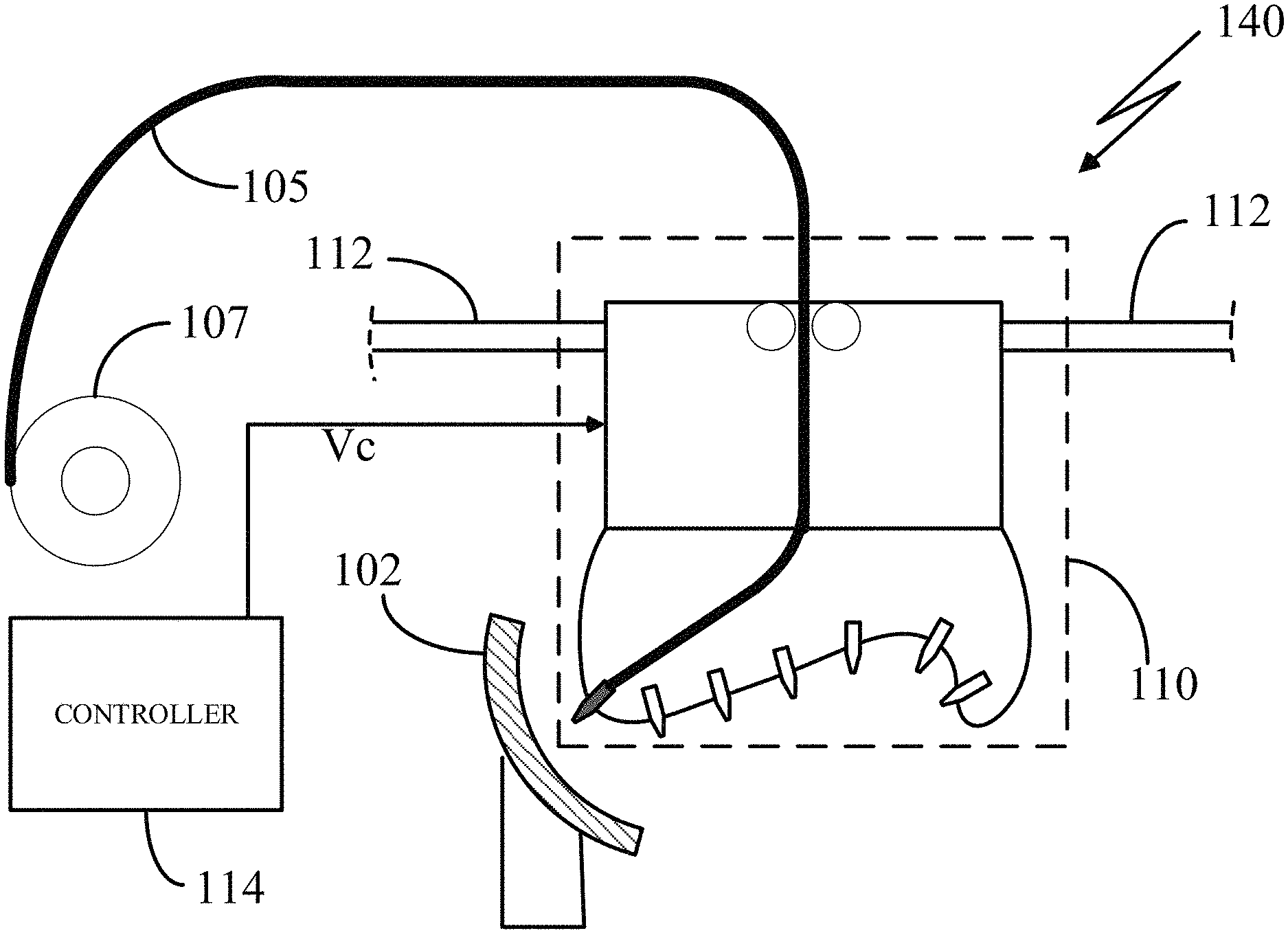
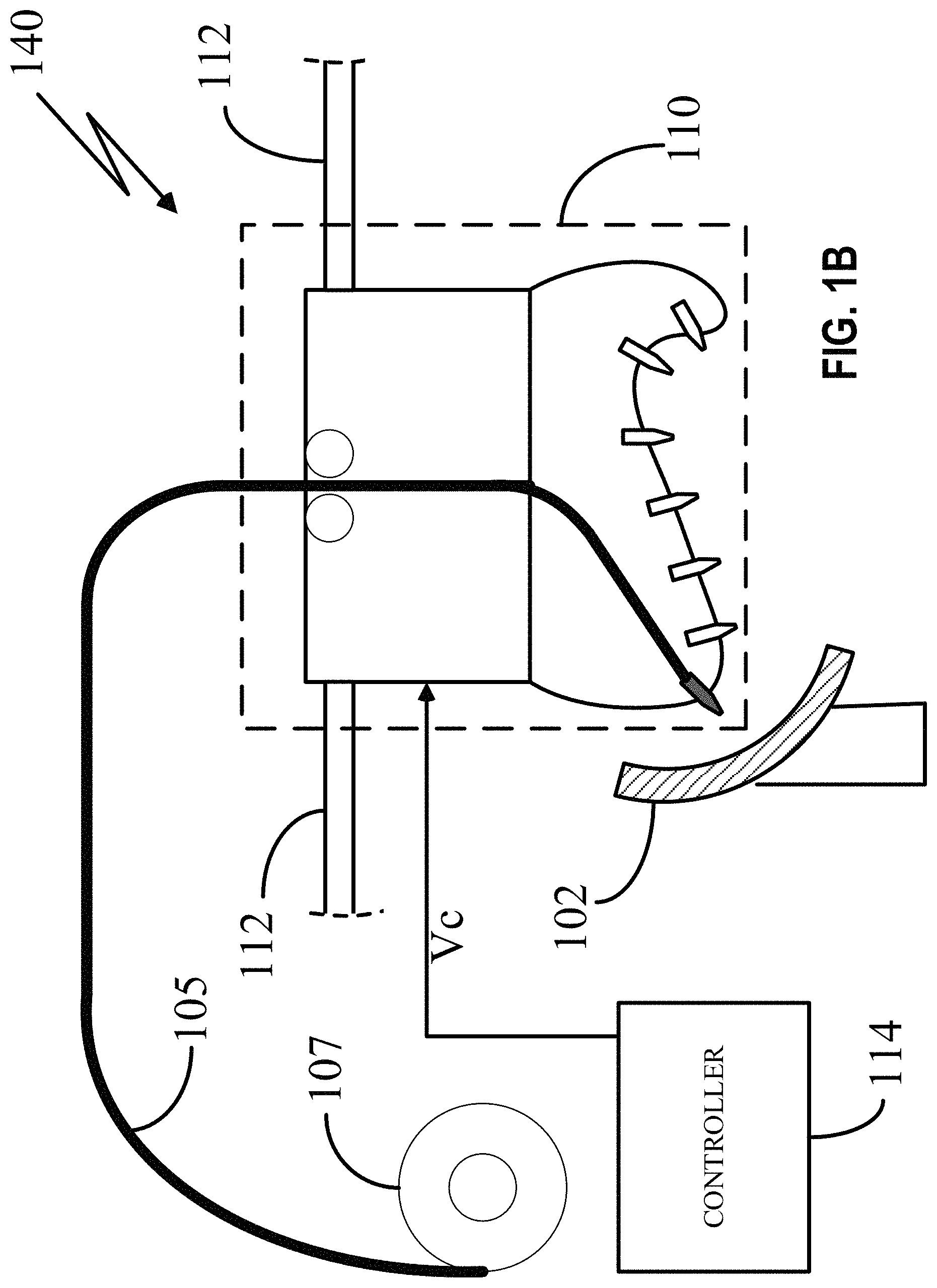
FIG. 1A illustrates a material extrusion printer 100 using a variable extruder head 110 according to the teachings herein. The material extrusion printer includes the variable extruder head 110, a moveable build stage 120, and a build plate 130 at the top of the build stage 120. The variable extruder head 110 receives a filament 105 and extrudes molten filament via a nozzle 108a to build an object 102. Like other illustrations herein, the figures, or elements illustrated in the figures, are not necessarily drawn to scale and certain objects may sometimes be magnified relative to the remainder of the apparatus to highlight various features or to add overall clarity. Variable extruder head 110 in FIG. 1A may represent such an enhanced view. It should also be noted in FIG. 1A that of the various candidate nozzles on extruder head 110, nozzle 108a may be identified as the nozzle that provides the most desirable angle for 3D printing that portion of object 102. As the build proceeds and the object's angle changes, other nozzles may be selected in some embodiments.
Responsive to printing instructions, the variable extruder head 110 moves about a horizontal (X-Y) plane of a Cartesian coordinate system 111 so that extrusion nozzle 108a extrudes the material to the object 102. The variable extruder head 110 and/or the build plate 130 can also move in the Z-direction of the Cartesian coordinate system 111 to adjust the height of the extruded material.
According to the teachings herein, the variable extruder head 110 can receive instructions to vary nozzle properties in a way that improves the build time and build quality of complex non-planar structures. For instance, as shown in FIG. 1A, using the variable extruder head 110, the material extrusion printer 100 can build the concave object 102 because the extrusion nozzles in this example are oriented at ideal angles and proximities to the build plate 130 (or object 102) to effect the desired concave print. As discussed above, nozzle diameters may also be adjusted depending on the desired resolution, shape, or both, of the printed object. For example, where high print resolution is desirable in an object, the nozzle diameter may be adjusted to be smaller. Where resolution is not as essential (e.g., at a portion of the object that will not be used, or that need not have aesthetic or functional value, etc.), the nozzle diameter may be increased to decrease overall print time.
While an exemplary embodiment of the dynamically-adjustable print nozzle includes shape memory alloy materials as discussed above, the disclosure is not so limited and any number of techniques may be used to implement the variable diameter nozzles. For example, the nozzle may have built within it a network of metallic elements that may be intertwined in a manner that results in increasing or decreasing the nozzle diameter. Still other embodiments may be equally suitable.
As one of ordinary skill in the art can appreciate, different filament materials can be used for building the object 102. Depending on the intended composition of the object 102 and the need for any support material for providing support to overhanging elements of the structure that might otherwise be subject to possible gravitational deformation or collapse, a plurality of materials may be used.
For clarity, basic convex or concave shapes may be used as illustrative print objects in the figures. It should be understood, however, that the 3-D printer of the present disclosure may efficiently render potentially highly complicated print objects that have numerous curvatures and unique shapes. For example, one such print object may incorporate a variety of both convex and concave shapes. Each shape of the print object can be efficiently rendered using the principles described herein.
FIG. 1B illustrates another perspective of a material extrusion minter 139 using the variable extruder head 110 according to the teachings herein. The material extrusion printer 140 includes a filament spool 107, the filament 105, a controller 114, and the variable extruder head 110 attached to a gantry or other supporting device 112. The filament 105 can be fed to the variable extruder head 110 from the filament spool 107, and the controller 114 can send instructions to the variable extruder head 110 via a control signal Vc. For instance, the controller 114 can send the control signal Yc to adjust the position of the variable extruder head 110 along the rod 112 and also in the Z-direction. A motor or actuator can be used to position the variable extruder head 110 above the object 102. Additionally, and advantageously, the controller can send the control signal Vc to vary nozzle properties, such as nozzle diameter and nozzle rotational axis; also the controller can be part of a closed loop feedback system. In this way, complex structures having convex and concave shapes and surfaces, like object 102, can be printed in less time with improved accuracy.
FIG. 2A illustrates a front view of the variable extruder head 110 for printing a concave surface. The variable extruder head 110 includes an upper section 202 and a lower section 204 and receives the control signal Vc. The upper section 202 includes a roller 206a and a roller 206b. The rollers 206a-b can pull the filament 105 (e.g. from the spool) into the variable extruder head 110. The lower section 204 includes nozzles 208a-g positioned at different locations and at different angles along the surface of the lower section 204.
In printing the concave surface of object 201, the control signal Vc can provide instructions to the variable extruder head 110 to control its position in the Cartesian coordinate system 111 and also to select one of the nozzles 208a-g. One of the nozzles 208a-g may be selected based on parameters of the build characteristics of object 201. For instance, as shown in FIG. 2A, in response to instructions from the control signal Vc, actuators may be used to guide the filament 105 through the nozzle 208a. In this way material can be extruded via nozzle 208a to the concave surface of object 201 with improved print accuracy and/or at an improved extrusion rate.
The actuator between rollers 206a-b may include, in one embodiment, additional sets of drive wheels used to feed the filament in a selected direction. In an embodiment, this begins with rollers 206a and 206b. Where, as here, multiple nozzles are used with one filament, additional drive wheels may be used to vector the filament in the direction of the nozzle through which the filament is to be extruded. If a set of drive wheels do not move under the command of the controller, the filament would not pass through that set of drive wheels and would not reach a given nozzle. If the controller instructs a set of drive wheels to move, they would grab onto the filament, which may be vectored in that direction. The sets of drive wheels may be housed in upper section 202 of FIG. 2A, right above the demarcation line between upper and lower sections 202 and 204. In lower section 204, a system of channels may be implemented through which the filament would flow. The channel that receives the filament from the corresponding drive wheel with which the channel is paired would send the filament to the nozzle at the other end of the channel.
In other exemplary embodiments, the material extrusion printer along with variable extruder head 110 may be configured such that, in response to instructions over control signal Vc, a more complex configuration of actuators may be used to guide the filament through more than one nozzle, either concurrently or sequentially. These embodiments may be capable of rendering very complex print objects, or may build print objects in a comparatively short time. Additionally, the control signal Vc can provide instructions to the variable extruder head 110 to select one of the nozzles 208a-g based on properties of the object 201.
FIG. 2B illustrates a front view of the variable extruder head 110 for printing a convex surface. In response to instructions from the control signal Vc, actuators may be used to guide the filament 105 through nozzle 208f In this way material can be extruded via nozzle 208f to the convex surface of object 222 with improved accuracy and/or at an improved extrusion rate.
In still another embodiment, the printer of FIG. 1B is used to additively manufacture portions of one or more nozzles, such as portions of nozzle 208f above. It will be appreciated that certain structures that comprise the nozzle may require a metallic substance or a material that can withstand higher temperatures than those of the filaments used in the material extrusion printer. In those cases, the nozzles may be additively manufactured in part using PBF type printers, or using a conventional non-additive manufacturing method. In another embodiment, the 3-D printer may be equipped with an assortment of custom nozzles through which the variable extruder head 110 can be modified automatically (e.g. robotically) or by hand to include different nozzles for different applications.
Although the embodiments of FIGS. 2A and 2B show the variable extruder head 110 as having seven nozzles 208a-g, other configurations are possible. For instance, the lower section 204 can have greater or fewer nozzles. Also, although the extruder head 110 shows a configuration using only one filament 105, other configurations, like those shown in FIGS. 3A-3C, using more than one filament are possible.
FIG. 3A illustrates a front view of a variable extruder head 310 using more than one filament configured according to a first embodiment. The variable extruder 310 is similar to the variable extruder head 110 except that it allows for the intake of more than one filament by replacing the upper section 202 with an upper section 302. The upper section 302 includes rollers 306a-b for pulling filament 305a into the extruder head 310, rollers 306c-d for pulling filament 305b into the extruder head 310, and rollers 306e-f for pulling filament 305c into the extruder head 310.
Using more than one filament, the variable extruder head 310 can advantageously reduce bends and routing angles that occur when a filament is guided to one of the nozzles 208a-g. In an exemplary embodiment, each of the filaments 305a-c can be devoted to a select subset of the nozzles. For instance, as shown in FIG. 3A, when printing the concave surface of object 201, the control signal Vc can send instructions to guide filament 305a to nozzle 208a. Filament 305a may be selected for a subset of nozzles closer to the left side of the lower section 204. For instance, filament 305a may be used for a subset of nozzles 208a-c to extrude material. While the extruder head 310 is illustrated in FIG. 3A as having specific numbers of filaments 305a-c and nozzles 208a-g operating in exemplary configurations, it will be appreciated that the number and configuration of these devices may vary in different embodiments to result in a variety of filament-bending profiles most appropriate for a given set of applications.
FIG. 3B illustrates a front view of the variable extruder head 310 using more than one filament configured according to a second embodiment. In the second embodiment the filament 305c is selected for extruding material through nozzle 208f to the convex surface of object 222. In this way a filament bend angle is reduced as compared to the filament bend angle in the variable extruder head 110 of FIG. 2B. The filament 305c can be selected for a subset of nozzles 208f-g. The actuators in upper portion 302 may be similar in principal to those identified and described with reference to FIG. 2B, except that additional or different techniques may be used to direct the appropriate filaments to the channels in lower portion 204 that feed the nozzles.
In some embodiments, the variable extruder head 310 includes some capability for rotational motion about its vertical axis in addition to its primary translational motion capability along the three axes. Thus, referring to nozzle 208f in FIG. 3B, in one embodiment Vc may instruct extruder head 310 to rotate slightly in one direction. This rotation of the extruder head 310 also causes nozzle 208f to rotate relative to the print object, which in turn changes the properties of the printer to accommodate different curvatures in a print object. More generally, this rotational capability means that the different nozzles 208a-g may all be further rotated when extruder head 310 rotates. In one embodiment, using these principles, virtually the entire rotational field from 0.degree. to 180.degree. may be available to use on a complex build object having sophisticated curvatures. The CAD program associated with the printer can provide a software-based solution that capitalizes on this capability and optimizes the print-out to include a range of relevant angles. The result can be a sophisticated build object printed quickly and, if desired, with a high resolution.
FIG. 3C illustrates a front view of the variable extruder head 310 using more than one filament 305a-c configured according to a third embodiment. In the third embodiment the filament 305b is selected for extruding material through nozzle 208d to the convex surface of object 322. In an embodiment, the filament 305b can be selected for a subset of nozzles 208d-e, while the filament 305a can be selected for a subset of nozzles 208a-c and the filament 305c can be selected for the remaining nozzles 208f-g.
Although FIGS. 3A-3C show the variable extruder head 310 as using three filaments 305a-c, other configurations having greater or fewer than three are possible. For instance, in embodiments where the lower section 204 has more than seven nozzles 208a-g, more than three filaments can be used to reduce filament bend angles.
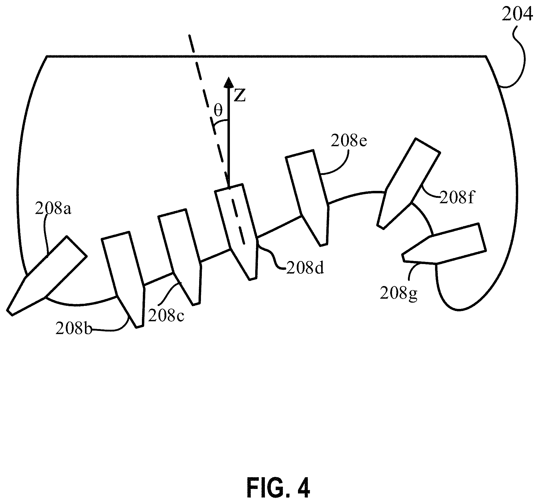
FIG. 4 illustrates a front view of the extruder nozzles within a lower section 204 of the variable extruder head 110 according to an embodiment. In the embodiment of FIG. 4, the lower section 204 includes nozzles 208a-g positioned at different angles with respect to a Z-axis direction of the Cartesian coordinate system 111. Additionally, the nozzles 208a-g can be positioned to have an alignment axis parallel to a normal to the surface of the lower section 204. For instance, as shown in FIG. 4, the nozzle 208d has an axis parallel to a surface normal vector which has an angle .theta. relative to the Z-axis. The surface structure of the lower section 204 can be tailored to allow for any arrangement of nozzle angles. For instance, the surface can be tailored to have a Bezier curve shape.
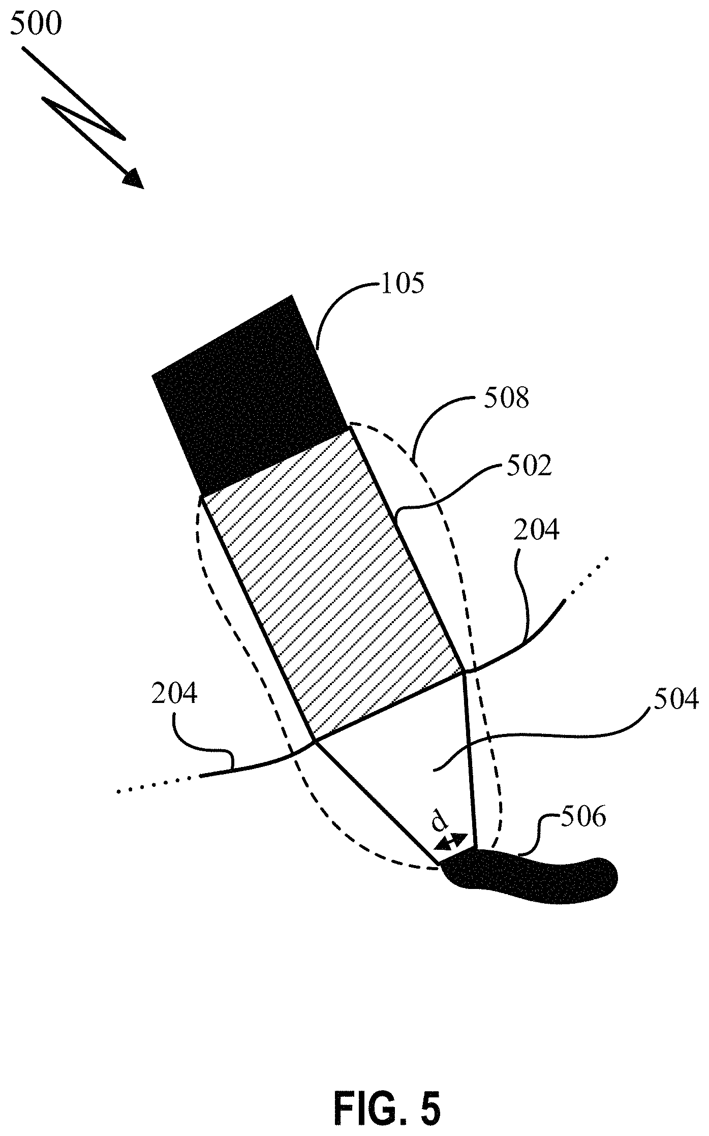
FIG. 5 illustrates a front view 500 of an extruder nozzle 508 according to an embodiment. The extruder nozzle 508 can be one of several extruder nozzles placed at angles along the surface of a lower section 204. The nozzle 508 comprises a filament liquefier chamber 502 and a nozzle head 504. Based on instructions received via control signal Vc, an actuator can guide the filament 105 into the nozzle 508. The filament 105 entering the nozzle 508 is heated within the filament liquefier chamber 502 so that molten material 506 is extruded from the tip of the nozzle head 504.
The control signal Vc can also be used to adjust the diameter d of the nozzle head 504. The diameter d of the nozzle head 504 can determine the resolution and build time of the printed object. As the diameter d decreases, the resolution can increase while the build time increases.
For instance, FIG. 6A illustrates a variable extruder nozzle 508 configured to have a first nozzle diameter d1 according to the teachings herein; and FIG. 6B illustrates the variable extruder nozzle 508 configured to have a second nozzle diameter d2, greater than d1 according to the teachings herein. For fine geometry sections of a build, the control signal Vc can send instructions to reduce diameter to d1, while for coarser geometry sections of a build, the control signal Vc can send instructions to increase diameter to d2. Although the concept of varying the diameter of a variable extruder nozzle 508 is shown with respect to a single nozzle, the concept may also be applied to the nozzles 208a-g described above. For instance, the variable extruder head 110 can have nozzles 208a-g, each with a controllable diameter as described herein.
FIG. 7 illustrates a cross section of a smart memory alloy (SMA) variable extruder nozzle 700 using SMA actuators 709a-b according to an embodiment. The SMA variable extruder nozzle 700 includes rollers 706a-b, a filament liquefier chamber 701, and nozzle segments 704a-b which are mechanically controlled by the SMA actuators 709a-b. The rollers 706a-b draw filament 705 into the filament liquefier chamber 701 where the filament 705 is heated to a molten state. A control signal can be used to control the manner in which the nozzle segments 704a-b adjust a nozzle diameter via the SMA actuators 709a-b. For instance, control signals can be used to cause the SMA actuators 709a-b to force a movement of the nozzle segments 704a-b.
The SMA variable extruder nozzle 700 can be used as a nozzle in one of the previous variable extruder heads (e.g. variable extruder head 110). Additionally, the SMA variable extruder nozzle 700 can be controlled via a control signal Vc within a closed loop or open loop system.
The nozzle segments 704a-b may be actuated via the SMA actuators 709a-b by instructions via a control signal in order to adjust an opening profile (diameter). Although, the SMA variable extruder nozzle 700 shows a cross section with two nozzle segments 704a-b, the nozzle can have multiple segments; and each of the segments may be actuated by an SMA actuator to vary an opening profile (diameter) of the nozzle.
Although actuation of the nozzle segments 704a-b is shown to occur via SMA actuators 709a-b, other actuator systems are possible. For instance, actuation may be achieved through a variety of technologies-hydraulic actuators, pneumatic actuators, linear actuators, electro-mechanical actuators, and other types of smart material actuators. In addition to SMA materials, shape memory polymers (SMPs) may be used to create actuators.
Additionally, the SMA variable extruder nozzle 700 can be part of a material extrusion-based additive manufacturing system. Also, as one of ordinary skill in the art can appreciate, SMAs are temperature sensitive; and an SMA actuation system can likewise be temperature sensitive.
As one of ordinary skill in the art can appreciate, SMA transition temperatures are typically between 10 to 100 degrees Celsius. An SMA can be heated to gain its shape prior to deformation and cooled to return to its deformed shape. SMAs typically operate through Joule heating, and the same principle can be applied to the SMA variable extruder nozzle 700 and SMA actuators 709a-b.
As described above, the variable extruder nozzle 700 and SMA actuators 709a-b can be connected to a closed-loop control system which can elevate the temperature of the SMA based on a variety of variables: material being extruded, temperature of the nozzle, instructions from computer aided design (CAD) via the control signal Vc. Instructions can further be based upon object (e.g. object 102) parameters including geometry, curvature, and the like. Instructions can be sent to the controller (e.g. controller 114) to adjust the temperature of the SMA by adding heat or providing cooling functionality.
The SMA actuators 709a-b can be connected to additional segments of the SMA variable extruder nozzle 700 to operate as actuators. The connection between the SMA actuators 709a-b and the nozzle segments 704a-b can be insulated thermally and electrically so that the heat from the nozzle area, tip, and surrounding regions do not heat the SMA.
To avoid unintended actuation, the SMA actuators 709a-b may in an embodiment be positioned so as to not be exposed to extreme and/or elevated temperature. The SMA actuators 709a-b can be placed in a thermally insulated location in the printer, sufficiently clear of the regions immediately surrounding the end of the extruder/nozzle segments. The SMA actuators 709a-b can be positioned away and/or insulated from heat producing elements of the SMA variable extruder nozzle 700. For instance, the SMA actuators 709a-b can be away from the extreme temperatures of the liquefier chamber 701; also isolation and/or insulation material can be placed between the SMA actuators 709a-b and heat producing elements of the SMA variable extruder nozzle 700. Also, a cooling system can be used to control and/or cool the SMA actuators 709a-b.
As shown in following FIGS. 8A-C, using SMA actuators 709a-b to control opening profiles can advantageously allow for a variety of opening profiles by varying a diameter of the SMA variable extruder nozzle 700.
FIG. 8A illustrates a cross section 800a of an opening profile of variable extruder nozzle segments 704a-b having a first diameter d0 according to an embodiment.
FIG. 8B illustrates a cross section 800c of an opening profile of variable extruder nozzle segments 704a-b having a second diameter d1 according to an embodiment.
FIG. 8C illustrates a cross section 800e of an opening profile of variable extruder nozzle segments 704a-b having a third diameter d2 according to an embodiment.
As illustrated by FIGS. 8A-8C, actuators, such as the SMA actuators 709a-b, can control diameter. In the embodiments of FIGS. 8A-8C, diameter d2 is greater than diameter d0, and diameter d1 is less than diameter d0.
FIG. 9 conceptually illustrates a method 900 of using a material extrusion printer according to an embodiment. The method 900 includes steps 901-904. In step 901 filament material (e.g. filament 105) is provided to a variable extruder head 110. In step 902 material is received by the variable extruder head 110. In step 903 layers are deposited sequentially. In step 904 a profile of at least one nozzle 904 is varied according to the teachings herein.
The above sub-processes represent non-exhaustive examples of specific techniques to accomplish objectives described in this disclosure. It will be appreciated by those skilled in the art upon perusal of this disclosure that other sub-processes or techniques may be implemented that are equally suitable and that do not depart from the principles of this disclosure.
The previous description is provided to enable any person skilled in the art to practice the various aspects described herein. Various modifications to these exemplary embodiments presented throughout this disclosure will be readily apparent to those skilled in the art, and the concepts disclosed herein may be applied to other techniques for additively manufacturing transport vehicles including automobiles, airplanes, boats, motorcycles, and the like.
Thus, the claims are not intended to be limited to the exemplary embodiments presented throughout the disclosure, but are to be accorded the full scope consistent with the language claims. All structural and functional equivalents to the elements of the exemplary embodiments described throughout this disclosure that are known or later come to be known to those of ordinary skill in the art are intended to be encompassed by the claims. Moreover, nothing disclosed herein is intended to be dedicated to the public regardless of whether such disclosure is explicitly recited in the claims. No claim element is to be construed under the provisions of 35 U.S.C. .sctn. 112(f), or analogous law in applicable jurisdictions, unless the element is expressly recited using the phrase "means for" or, in the case of a method claim, the element is recited using the phrase "step for."
* * * * *
D00000
D00001
D00002
D00003
D00004
D00005
D00006
D00007
D00008
D00009
D00010
D00011
D00012

D00013

XML
uspto.report is an independent third-party trademark research tool that is not affiliated, endorsed, or sponsored by the United States Patent and Trademark Office (USPTO) or any other governmental organization. The information provided by uspto.report is based on publicly available data at the time of writing and is intended for informational purposes only.
While we strive to provide accurate and up-to-date information, we do not guarantee the accuracy, completeness, reliability, or suitability of the information displayed on this site. The use of this site is at your own risk. Any reliance you place on such information is therefore strictly at your own risk.
All official trademark data, including owner information, should be verified by visiting the official USPTO website at www.uspto.gov. This site is not intended to replace professional legal advice and should not be used as a substitute for consulting with a legal professional who is knowledgeable about trademark law.