Bonded brazing ring system and method for adhering a brazing ring to a tube
Campbell , et al. A
U.S. patent number 10,744,601 [Application Number 15/225,293] was granted by the patent office on 2020-08-18 for bonded brazing ring system and method for adhering a brazing ring to a tube. This patent grant is currently assigned to BELLMAN-MELCOR DEVELOPMENT, LLC. The grantee listed for this patent is Bellman-Melcor Development, LLC. Invention is credited to Steven Campbell, John Scott.


| United States Patent | 10,744,601 |
| Campbell , et al. | August 18, 2020 |
Bonded brazing ring system and method for adhering a brazing ring to a tube
Abstract
A bonded brazing ring secured to an end of a tube having a solvent or a solvent with a binder applied to the surface of the tube, and a method of adhering a brazing ring to a tube using a solvent or a solvent with a binder is provided. The brazing ring is secured to the tube prior to a brazing operation.
| Inventors: | Campbell; Steven (Mokena, IL), Scott; John (New Lenox, IL) | ||||||||||
|---|---|---|---|---|---|---|---|---|---|---|---|
| Applicant: |
|
||||||||||
| Assignee: | BELLMAN-MELCOR DEVELOPMENT, LLC
(Tinley Park, IL) |
||||||||||
| Family ID: | 58053705 | ||||||||||
| Appl. No.: | 15/225,293 | ||||||||||
| Filed: | August 1, 2016 |
Prior Publication Data
| Document Identifier | Publication Date | |
|---|---|---|
| US 20170036306 A1 | Feb 9, 2017 | |
Related U.S. Patent Documents
| Application Number | Filing Date | Patent Number | Issue Date | ||
|---|---|---|---|---|---|
| 62202457 | Aug 7, 2015 | ||||
| Current U.S. Class: | 1/1 |
| Current CPC Class: | B23K 1/203 (20130101); B23K 35/0222 (20130101); F16L 13/08 (20130101); F16L 43/005 (20130101); B23K 35/0227 (20130101); B23K 2101/06 (20180801) |
| Current International Class: | B23K 35/02 (20060101); B23K 1/20 (20060101); F16L 43/00 (20060101); F16L 13/08 (20060101) |
References Cited [Referenced By]
U.S. Patent Documents
| 400869 | April 1889 | Norton et al. |
| 607504 | July 1898 | Crowther |
| 1650905 | December 1925 | Mills |
| 1629748 | May 1927 | Stoody |
| 1865169 | July 1927 | Candy |
| 1968618 | February 1932 | Padgett et al. |
| 1972315 | September 1934 | Ramey |
| 2005189 | June 1935 | Herr |
| 2055276 | September 1936 | Brownsdon et al. |
| 2279284 | April 1942 | Wassermann |
| 2334609 | November 1943 | Cox |
| 2442087 | May 1948 | Kennedy |
| 2465503 | March 1949 | Woods |
| 2499641 | March 1950 | Goody |
| 2565477 | August 1951 | Crowell et al. |
| 2785285 | March 1957 | Bernard |
| 2845700 | August 1958 | Bagno |
| 2927043 | March 1960 | Stetson |
| 2958941 | November 1960 | Goerg |
| 3033713 | May 1962 | Bielenberg et al. |
| 3051822 | August 1962 | Bernard et al. |
| 3077131 | February 1963 | McShane |
| 3162551 | December 1964 | Short |
| 3198560 | August 1965 | Collins |
| 3239125 | March 1966 | Sherlock |
| 3245141 | April 1966 | Gruetjen |
| 3290772 | December 1966 | Crouch |
| 3318729 | May 1967 | Siegle et al. |
| 3365565 | January 1968 | Claussen |
| 3452419 | July 1969 | Hillert |
| 3534390 | October 1970 | Wood et al. |
| 3542998 | November 1970 | Huff |
| 3555240 | January 1971 | Gloor et al. |
| 3558851 | January 1971 | Takeshi |
| 3610663 | October 1971 | Lago |
| 3619429 | November 1971 | Torigai et al. |
| 3620830 | November 1971 | Kramer |
| 3620869 | November 1971 | Stump et al. |
| 3639721 | February 1972 | Hubbel |
| 3642998 | February 1972 | Jennings |
| 3688967 | September 1972 | Arikawa et al. |
| 3695795 | October 1972 | Jossick |
| 3703254 | November 1972 | Maierson et al. |
| 3745644 | July 1973 | Moyer et al. |
| 3935414 | January 1976 | Ballass et al. |
| 3967036 | June 1976 | Sadowski |
| 3980859 | September 1976 | Leonard |
| 4041274 | August 1977 | Sadowski |
| 4121750 | October 1978 | Schoer et al. |
| 4134196 | January 1979 | Yamaji et al. |
| 4174962 | November 1979 | Frantzreb, Sr. et al. |
| 4214145 | July 1980 | Zvanut et al. |
| 4301211 | November 1981 | Sloboda |
| 4379811 | April 1983 | Puschner et al. |
| 4396822 | August 1983 | Kishida et al. |
| 4430122 | February 1984 | Pauga |
| 4447472 | May 1984 | Minnick et al. |
| 4493738 | January 1985 | Collier et al. |
| 4497849 | February 1985 | Hughes et al. |
| 4571352 | February 1986 | Aoki |
| 4587097 | May 1986 | Rabinkin et al. |
| 4587726 | May 1986 | Holmgren |
| 4624860 | November 1986 | Alber et al. |
| 4708897 | November 1987 | Douchy |
| 4762674 | August 1988 | Cheng et al. |
| 4785029 | November 1988 | Honma et al. |
| 4785092 | November 1988 | Nanba et al. |
| 4800131 | January 1989 | Marshall et al. |
| 4831701 | May 1989 | Yutaka |
| 4900895 | February 1990 | Marshall |
| 4901909 | February 1990 | George |
| 4993054 | February 1991 | Ujari |
| 5098010 | March 1992 | Carmichael et al. |
| 5175411 | December 1992 | Barber |
| 5184767 | February 1993 | Estes |
| 5219425 | June 1993 | Nishikawa et al. |
| 5280971 | January 1994 | Tokutake et al. |
| 5316206 | May 1994 | Syslak et al. |
| 5360158 | November 1994 | Conn et al. |
| 5418072 | May 1995 | Baldantoni et al. |
| 5575933 | November 1996 | Ni |
| 5749971 | May 1998 | Ni |
| 5759707 | June 1998 | Belt et al. |
| 5781846 | July 1998 | Jossick |
| 5791005 | August 1998 | Grabowski et al. |
| 5806752 | September 1998 | Van Evans et al. |
| 5820939 | October 1998 | Popoola et al. |
| 5903814 | May 1999 | Miura et al. |
| 5917141 | June 1999 | Naquin |
| 6093761 | July 2000 | Schofalvi |
| 6186390 | February 2001 | Tadauchi et al. |
| 6204316 | March 2001 | Schofalvi |
| 6244397 | June 2001 | Kars |
| 6248860 | June 2001 | Sant'Angelo et al. |
| 6264062 | July 2001 | Lack et al. |
| 6277210 | August 2001 | Schuster |
| 6317913 | November 2001 | Kilmer et al. |
| 6344237 | February 2002 | Kilmer et al. |
| 6376585 | April 2002 | Schofalvi et al. |
| 6395223 | May 2002 | Schuster et al. |
| 6409074 | June 2002 | Katoh et al. |
| 6417489 | July 2002 | Blankenship et al. |
| 6426483 | July 2002 | Blankenship et al. |
| 6432221 | August 2002 | Seseke-Koyro et al. |
| 6497770 | December 2002 | Watsuji et al. |
| 6598782 | July 2003 | Wieres et al. |
| 6608286 | August 2003 | Jiang |
| 6680359 | January 2004 | Schoenheider |
| 6713593 | March 2004 | Ree et al. |
| 6733598 | May 2004 | Swidersky et al. |
| 6830632 | December 2004 | Fuerstenau et al. |
| 6846862 | January 2005 | Schofalvi et al. |
| 6864346 | March 2005 | Schoenheider |
| 6872465 | March 2005 | Soga et al. |
| 6881278 | April 2005 | Amita et al. |
| 6960260 | November 2005 | Goto |
| 7022415 | April 2006 | Schnittgrund |
| 7267187 | September 2007 | Kembaiyan |
| 7337941 | March 2008 | Scott et al. |
| 7442877 | October 2008 | Kamata et al. |
| 7858204 | December 2010 | Campbell et al. |
| RE42329 | May 2011 | Fuerstenau et al. |
| 8274014 | September 2012 | Campbell et al. |
| RE44343 | July 2013 | Fuerstenau et al. |
| 8507833 | August 2013 | Belohlav |
| 8740041 | June 2014 | Visser et al. |
| 9095937 | August 2015 | Campbell et al. |
| 2002/0020468 | February 2002 | Schuster et al. |
| 2003/0141350 | July 2003 | Noro et al. |
| 2003/0203137 | October 2003 | Teshima et al. |
| 2004/0009358 | January 2004 | Scott |
| 2004/0171721 | September 2004 | Esemplare |
| 2005/0051598 | March 2005 | Heminway et al. |
| 2005/0089440 | April 2005 | Kembaiyan |
| 2007/0093574 | April 2007 | Esemplare |
| 2007/0251602 | November 2007 | Gagnon, Jr. et al. |
| 2008/0017696 | January 2008 | Urech et al. |
| 2009/0014093 | January 2009 | Campbell et al. |
| 2009/0020276 | January 2009 | Ueda et al. |
| 2009/0077736 | March 2009 | Loberger et al. |
| 2009/0101238 | April 2009 | Jossick et al. |
| 2009/0200363 | August 2009 | Means et al. |
| 2009/0261574 | October 2009 | Blueml et al. |
| 2010/0122997 | May 2010 | Liu |
| 2010/0219231 | September 2010 | Means et al. |
| 2011/0023319 | February 2011 | Fukaya et al. |
| 2011/0089222 | April 2011 | Campbell et al. |
| 2011/0123824 | May 2011 | Belohlav et al. |
| 2012/0207643 | August 2012 | Belohlav et al. |
| 2013/0017393 | January 2013 | Campbell et al. |
| 2014/0008416 | January 2014 | Vasser et al. |
| 2016/0008929 | January 2016 | Campbell |
| 2016/0067833 | March 2016 | Campbell et al. |
| 45936179 | Jul 1980 | AU | |||
| 878006 | Jan 1980 | BE | |||
| 1146025 | May 1983 | CA | |||
| 1303605 | Jun 1992 | CA | |||
| ZL 200780027486.6 | Aug 2012 | CN | |||
| 1298967 | Jul 1969 | DE | |||
| 2522589 | Dec 1975 | DE | |||
| 2931040 | Feb 1980 | DE | |||
| 8910519 | Oct 1989 | DE | |||
| 60120250 | Apr 2007 | DE | |||
| 323379 | Feb 1980 | DK | |||
| 0991697 | Apr 2000 | EP | |||
| 1127653 | Aug 2001 | EP | |||
| 483021 | Apr 1980 | ES | |||
| 2349392 | Nov 1977 | FR | |||
| 2432360 | Feb 1980 | FR | |||
| 692710 | Jun 1953 | GB | |||
| 1180735 | Feb 1970 | GB | |||
| 1481140 | Jul 1977 | GB | |||
| 2027617 | Feb 1980 | GB | |||
| 48459 | Jan 1985 | IE | |||
| 152853 | Apr 1984 | IN | |||
| 1193704 | Aug 1988 | IT | |||
| 55045591 | Mar 1980 | JP | |||
| 58000375 | Jan 1983 | JP | |||
| 62034698 | Feb 1987 | JP | |||
| 63040697 | Feb 1988 | JP | |||
| 63303694 | Dec 1988 | JP | |||
| 01066093 | Mar 1989 | JP | |||
| 2179384 | Jul 1990 | JP | |||
| 3005094 | Jan 1991 | JP | |||
| 3204169 | Sep 1991 | JP | |||
| 4371392 | Dec 1992 | JP | |||
| 6007987 | Jan 1994 | JP | |||
| 11347783 | Dec 1999 | JP | |||
| 2005512655 | Apr 2002 | JP | |||
| 302328 | Aug 2012 | MX | |||
| 7905877 | Feb 1980 | NL | |||
| 792504 | Feb 1980 | NO | |||
| 7906495 | Feb 1980 | SE | |||
| 1999/000444 | Jan 1999 | WO | |||
| 2000039172 | Jul 2000 | WO | |||
| 2000052228 | Sep 2000 | WO | |||
| 2000064626 | Nov 2000 | WO | |||
| 2002000569 | Jan 2002 | WO | |||
| 2002031023 | Apr 2002 | WO | |||
| 2003068447 | Aug 2003 | WO | |||
| 2003089176 | Oct 2003 | WO | |||
| 2004061871 | Jul 2004 | WO | |||
| 2004094328 | Nov 2004 | WO | |||
| 2007058969 | May 2007 | WO | |||
| 2007058969 | May 2007 | WO | |||
| 2007140236 | Dec 2007 | WO | |||
| 2008148088 | Dec 2008 | WO | |||
| 2016007271 | Jan 2016 | WO | |||
| 7903893 | Jul 1980 | ZA | |||
Other References
|
European Search Report dated Jun. 22, 2012 for PCT/US2006/043856. cited by applicant . Examination Report of SIPO for CN 2007800274866 dated Dec. 17, 2010. cited by applicant . Extended European Search Report for EP 07762314.8 dated Dec. 13, 2012. cited by applicant . International Preliminary Report on Patentability for PCT/US2008/064871 dated Dec. 1, 2009. cited by applicant . International Preliminary Report on Patentability for PCT/US2007/069636 dated Dec. 11, 2008. cited by applicant . International Preliminary Report on Patentability for PCT/US2006/043856 dated Nov. 9, 2006. cited by applicant . International Preliminary Report on Patentability for PCT/US2007/025309 dated Jun. 16, 2009. cited by applicant . International Search Report for PCT/US2008/064871 dated Dec. 4, 2008. cited by applicant . International Search Report for PCT/US2007/069636 dated Nov. 8, 2007. cited by applicant . International Search Report for PCT/US2007/025309 dated Apr. 9, 2008. cited by applicant . International Search Report for PCT/US2006/043856 dated Dec. 21, 2007. cited by applicant . Written Opinion of International Searching Authority for PCT/US2006/043856 dated May 10, 2008. cited by applicant . Written Opinion of International Searching Authority for PCT/US2007/069636 dated May 24, 2007. cited by applicant . Written Opinion of International Searching Authority for PCT/US2007/025309 dated Dec. 11, 2007. cited by applicant . Written Opinion of International Searching Authority for PCT/US2008/064871 dated Nov. 25, 2009. cited by applicant . Belohlav, A.; "Understanding Brazing Fundamentals"; The American Welder, Sep.-Oct. 2000; Jul. 1, 2008; retrieved from <http://www.aws.org/wj/amwelder/9-00/fundamentals.html>. cited by applicant . Omni Technologies Corporation; "SIL-CORE Product Catalog"; undated (6 pages). cited by applicant . Day, S.A.; Material Safety Data Sheet for "Aluminum Flux Cored Wire and Rings"; pp. 1-5; Feb. 23, 2004 (5 pages). cited by applicant . Day, S.A.; Material Safety Data Sheet for "Flux Coating Part `A`"; pp. 1-6; May 2, 2006 (6 pages). cited by applicant . Day, S.A.; Material Safety Data Sheet for "Flux Coating Part `B`"; pp. 1-3; May 2, 2006 (3 pages). cited by applicant . US Patent Office, International Search Report and Written Opinion of International Searching Authority for PCT/US2015/036606 dated Nov. 24, 2015 (11 pages). cited by applicant . European Patent Office, Examination Report for EP Application No. 07762314.8 dated Mar. 24, 2016 (6 pages). cited by applicant. |
Primary Examiner: Schatz; Christopher T
Attorney, Agent or Firm: Vorys, Sater, Seymour and Pease LLP Miller, II; Rex W.
Parent Case Text
CROSS-REFERENCE TO RELATED APPLICATIONS
The present invention claims the benefit of U.S. Provisional Patent Application Ser. No. 62/202,457 filed Aug. 7, 2015, the contents of which are incorporated herein by reference.
Claims
We claim:
1. A method of adhering a brazing ring to a tube comprising: providing a tube having a first end; loading a first brazing ring on the first end of the tube having a channel of flux exposed toward an outer surface of the first end of the tube; causing a binder in the exposed flux of the first brazing ring to partially activate and adhere to the outer surface of the first end of the tube, transporting the tube and the first brazing ring after causing the binder in the exposed flux of the first brazing ring to partially activate and adhere to the outer surface of the first end of the tube; and, heating the brazing ring to a temperature sufficient to allow the flux to melt and flow out of the first brazing ring after transporting the tube and the first brazing ring.
2. The method of claim 1 wherein the step of causing the binder in the exposed flux of the first brazing ring to partially activate and adhere to the outer surface of the first end of the tube comprises: applying a first layer of a solvent to the first end of the tube.
3. The method of claim 2 wherein the step of applying a first layer of a solvent to the first end of the tube comprises: applying acetone to the first end of the tube.
4. The method of claim 1 further comprising: providing a second end of the tube.
5. The method of claim 4 further comprising: loading a second brazing ring on the second end of the tube having a channel of flux exposed toward an outer surface of the second end of the tube; and, causing a binder in the exposed flux of the second brazing ring to partially activate and adhere to the outer surface of the second end of the tube.
6. The method of claim 5 wherein the step of causing the binder in the exposed flux of the second brazing ring to partially activate and adhere to the outer surface of the second end of the tube comprises: applying a second layer of solvent to the second end of the tube.
7. The method of claim 6 wherein the step of applying a second layer of solvent to the second end of the tube comprises: applying acetone to the second end of the tube.
8. The method of claim 1 wherein the step of causing the binder in the exposed flux of the first brazing ring to partially activate and adhere to the outer surface of the first end of the tube comprises: applying a first layer of a solvent with a binder to the first end of the tube.
9. The method of claim 5 wherein the step of causing the binder in the exposed flux of the second brazing ring to partially activate and adhere to the outer surface of the second end of the tube comprises: applying a second layer of a solvent with a binder to the second end of the tube.
Description
FEDERALLY SPONSORED RESEARCH OR DEVELOPMENT
N/A
FIELD OF THE INVENTION
The present invention generally relates to a bonded brazing ring system and a method for adhering the brazing ring to a tube so that the ring does not fall off the tube prior to a brazing operation.
BACKGROUND OF THE INVENTION
Return bends and other tubing for industrial use (e.g., automotive, air conditioning and refrigerating systems) are typically connected to other components of a system in a brazing operation. A brazing material--typically in the form of a ring having an open end with a small gap--is melted where the bend or tube connects to the system to provide a sealed joint. A flux is typically utilized in this operation and can be held by the brazing material.
Brazing rings are typically loaded onto return bends prior to transit of the return bends to the system. The brazing rings are formed having a smaller diameter than the ends of the return bends and thus are slightly expanded when placed on the ends. While this expansion provides a mechanical mechanism (e.g., tension) for holding onto the ends of the return bend, other factors, such as time, environmental conditions, jarring during transit, etc. can cause the tension holding the brazing rings to soften and allow the rings to fall off.
The present invention provides an improved brazing ring system and method of placing the brazing ring on the return bend to avoid loss during transit.
SUMMARY OF THE INVENTION
The present invention provides a brazing ring that is adhered to a return bend or other similar tubing prior to a brazing operation, and a method for adhering the brazing ring to the bend or other tubing. This allows for safe transport of the return bend loaded with brazing rings without concern that the brazing rings will fall off during transit.
In accordance with one embodiment of the invention, a secured brazing ring system is provided. The system comprises a tube having a first end portion. A first brazing ring having a brazing material and a channel of flux with an exposed surface is secured about the first end portion of the tube. The exposed surface of flux faces an outer surface of the first end of the tube. A layer of a solvent or a solvent with a binder is interposed between the outer surface of the first end portion of the tube and the exposed surface of flux. The solvent or solvent with binder acts to adhere the brazing ring to the end of the tube.
The solvent can be, for example, acetone. Acetone causes a binder in the exposed flux to partially activate and adhere to the end portion of the tube.
The tube can be part of a return bend. The return bend includes a second end portion. Accordingly, a second brazing ring having a brazing material and a channel of flux with an exposed surface can be secured about the second end portion of the tube. Similar to the first brazing ring, the exposed surface of flux faces an outer surface of the second end portion of the tube and a layer of solvent or a solvent with a binder is interposed between the outer surface of the second end portion of the tube and the exposed surface of flux. Again, the solvent can be acetone.
In accordance with another embodiment of the invention, a method of adhering a brazing ring to a tube is provided. The method comprises providing a tube having a first end, applying a layer of a solvent or a solvent with a binder to the first end, and loading a first brazing ring on the first end having a channel of flux exposed toward an outer surface of the first end.
The solvent can be, for example, acetone. In this instance, the exposed flux partially activates upon contact with the acetone to adhere the brazing ring to the first end of the tube.
The method can further include providing a second end of the tube, applying a layer of a solvent or a solvent with a binder to the second end, and loading a second brazing ring on the second end having a channel of flux exposed toward an outer surface of the second end.
Again, the solvent can be acetone. In this instance, the exposed flux partially activates upon contact with the acetone to adhere the brazing ring to the second end of the tube.
In accordance with another embodiment of the invention another embodiment of the invention a method of adhering a brazing ring to a tube comprises providing a tube having a first end, loading a first brazing ring on the first end of the tube having a channel of flux exposed toward an outer surface of the first end of the tube and causing a binder in the exposed flux of the first brazing ring to partially activate and adhere to the outer surface of the first end of the tube.
The step of causing a binder in the exposed flux of the first brazing ring to partially activate and adhere to the outer surface of the first end of the tube can be accomplished by applying a solvent, such as acetone, or a solvent with a binder. This method can also be applied to a second end of the tube.
Further aspects of the invention are disclosed in the Figures, and are described herein.
BRIEF DESCRIPTION OF THE DRAWINGS
To understand the present invention, it will now be described by way of example, with reference to the accompanying drawings and attachments in which:
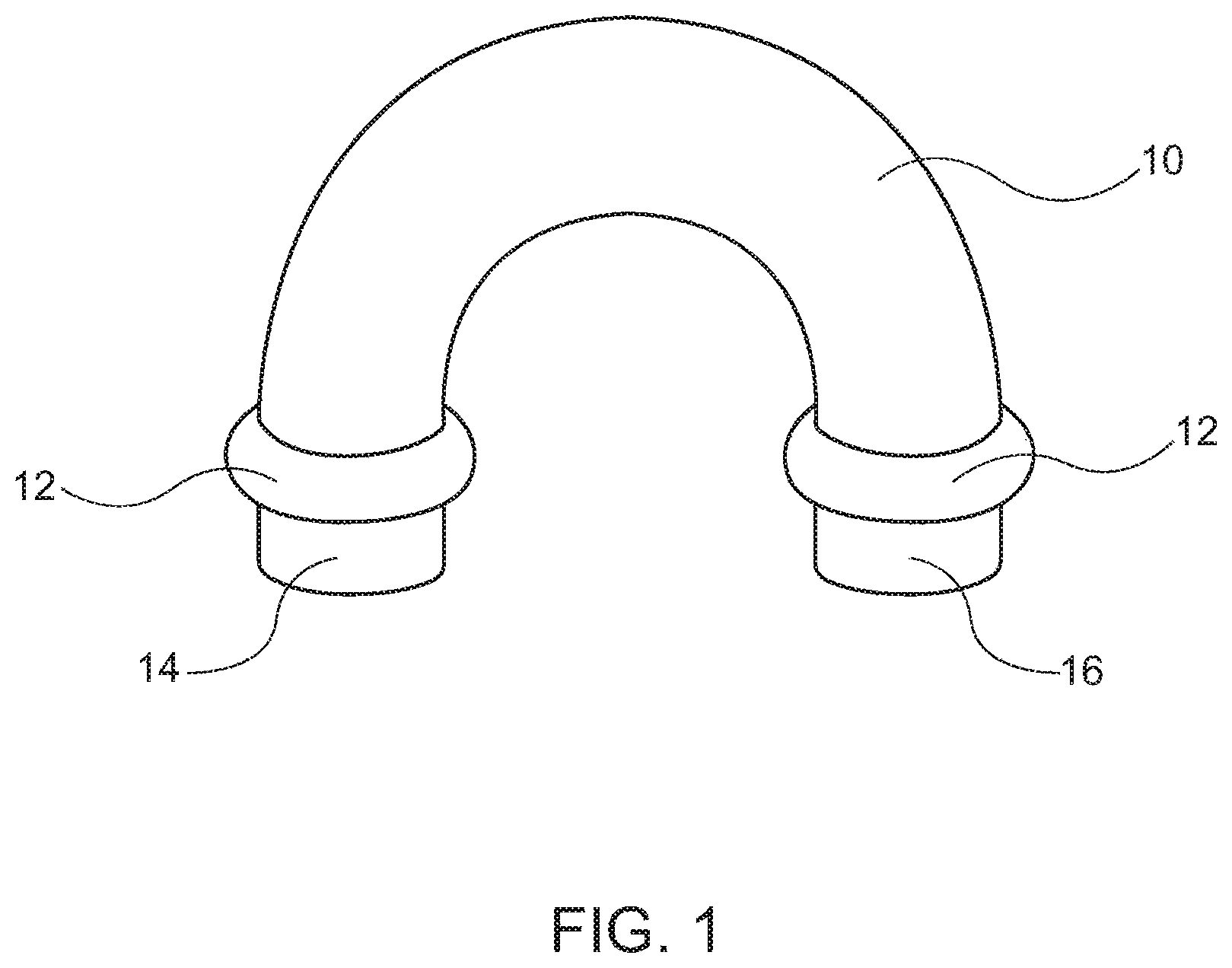
FIG. 1 is a perspective view of a first and second brazing ring on the ends of a return bend;
FIG. 2 is a perspective view of a brazing ring used in FIG. 1;
FIG. 3 is a cross-sectional view of the brazing ring of FIG. 2; and,
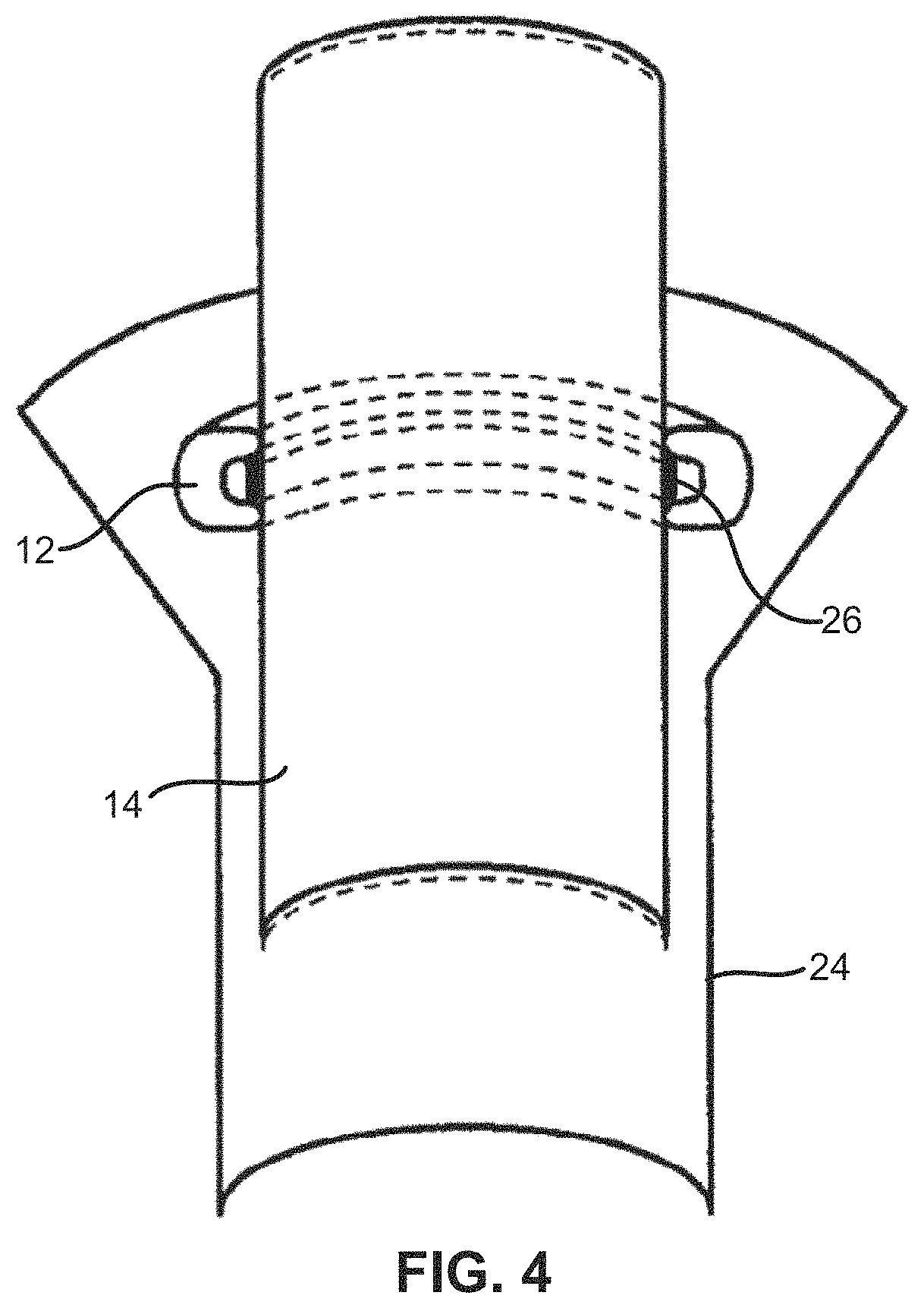
FIG. 4 is a partial cross-sectional view of the brazing ring around the end of one leg of a return bend positioned in a receiving tube prior to a brazing operation.
DETAILED DESCRIPTION
While this invention is susceptible of embodiments in many different forms, there is shown in the drawings, and will herein be described in detail preferred embodiments of the invention with the understanding that the present disclosure is to be considered as an exemplification of the principles of the invention and is not intended to limit the broad aspect of the invention to the embodiments illustrated.
The present invention is directed to a brazing ring that adheres to a tube, such as an end of a return bend during transit (i.e., prior to a brazing operation), and to a method for adhering the brazing ring to the return bend.
FIG. 1 shows a typical return bend 10 (i.e., a bend that connects to two parallel tubes of a system, such as an air conditioning system), with a first brazing ring 12 on a first end 14 of one leg of the return bend 10, and a second brazing ring 12 on a second end 16 of the other leg of the return bend 10. As discussed below, the brazing rings 12 are adhered to the ends 14, 16 of the return bend 10 so that they do not fall off during transit.
As illustrated in FIGS. 2 and 3, each brazing ring 12 includes an outer layer of brazing material 18 surrounding a channel of flux material 20. The top surface of the flux material 20 in the channel is exposed. Referring back to FIG. 1, it is clear that the exposed flux material 20 is in contact with the outer wall or surface of the ends 14, 16 of the return bend 10 (this is also evident in the cross-sectional view of FIG. 4).
The brazing ring 12 is formed from a wire of material bent into a circular shape. This leaves a slight opening 22 between the ends of the ring 12. A brazing ring of the type disclosed in U.S. Pat. No. 9,095,937 (which is incorporated herein by reference) can be utilized in this embodiment of the invention.
To adhere the brazing rings 12 to the return bend 10, a solvent 26, preferably acetone, is applied to the ends of the return bend 10. This can be accomplished by painting or spaying the acetone 26 onto the return bend 10 prior to loading the brazing rings 12 onto the ends of the return bend 10. The brazing rings 12 are then loaded to the return bend 10 and the applied acetone reacts to the exposed flux 20. This reaction slightly activates a binder in the flux 20 which acts like a very effective glue that causes the brazing rings 12 to adhere to the ends 14, 16 of the return bend 10. This adherence allows for transit of the return bend 10 without risk of losing the brazing rings 12.
As illustrated in FIG. 4, the ends 14, 16 (only one end 14 is shown) of the return bend 10 are positioned in a receiving tube 24 (e.g., of an air conditioning system). They can then be subjected to a brazing operation.
While acetone is preferred, other materials, such as another solvent or a solvent with binder may also be used. Additionally, other brazing structures can be used with this invention. Moreover, the tubes and corresponding brazing rings do not have to be circular or round in cross-section, but can also be other geometric shapes.
Many modifications and variations of the present invention are possible in light of the above teachings. It is, therefore, to be understood within the scope of the appended claims the invention may be protected otherwise than as specifically described.
* * * * *
References
D00000
D00001
D00002
D00003
XML
uspto.report is an independent third-party trademark research tool that is not affiliated, endorsed, or sponsored by the United States Patent and Trademark Office (USPTO) or any other governmental organization. The information provided by uspto.report is based on publicly available data at the time of writing and is intended for informational purposes only.
While we strive to provide accurate and up-to-date information, we do not guarantee the accuracy, completeness, reliability, or suitability of the information displayed on this site. The use of this site is at your own risk. Any reliance you place on such information is therefore strictly at your own risk.
All official trademark data, including owner information, should be verified by visiting the official USPTO website at www.uspto.gov. This site is not intended to replace professional legal advice and should not be used as a substitute for consulting with a legal professional who is knowledgeable about trademark law.