Adsorbent materials and methods of adsorbing carbon dioxide
Ravikovitch , et al. A
U.S. patent number 10,744,449 [Application Number 15/351,693] was granted by the patent office on 2020-08-18 for adsorbent materials and methods of adsorbing carbon dioxide. This patent grant is currently assigned to Exxonmobil Upstream Research Company, Georgia Tech Research Corporation. The grantee listed for this patent is ExxonMobil Upstream Research Company, Georgia Tech Research Corporation. Invention is credited to Rohan V. Awati, Hanjun Fang, Preeti Kamakoti, Ambarish R. Kulkarni, Charanjit Paur, Peter I Ravikovitch, David Sholl, Karl G. Strohmaier.


| United States Patent | 10,744,449 |
| Ravikovitch , et al. | August 18, 2020 |
Adsorbent materials and methods of adsorbing carbon dioxide
Abstract
Methods of designing zeolite materials for adsorption of CO.sub.2. Zeolite materials and processes for CO.sub.2 adsorption using zeolite materials.
| Inventors: | Ravikovitch; Peter I (Spring, TX), Sholl; David (Atlanta, GA), Paur; Charanjit (Spring, TX), Strohmaier; Karl G. (Spring, TX), Fang; Hanjun (Atlanta, GA), Kulkarni; Ambarish R. (Atlanta, GA), Awati; Rohan V. (Atlanta, GA), Kamakoti; Preeti (Spring, TX) | ||||||||||
|---|---|---|---|---|---|---|---|---|---|---|---|
| Applicant: |
|
||||||||||
| Assignee: | Exxonmobil Upstream Research
Company (Spring, TX) Georgia Tech Research Corporation (Atlanta, GA) |
||||||||||
| Family ID: | 57485895 | ||||||||||
| Appl. No.: | 15/351,693 | ||||||||||
| Filed: | November 15, 2016 |
Prior Publication Data
| Document Identifier | Publication Date | |
|---|---|---|
| US 20170136405 A1 | May 18, 2017 | |
Related U.S. Patent Documents
| Application Number | Filing Date | Patent Number | Issue Date | ||
|---|---|---|---|---|---|
| 62337991 | May 18, 2016 | ||||
| 62255789 | Nov 16, 2015 | ||||
| Current U.S. Class: | 1/1 |
| Current CPC Class: | B01J 20/18 (20130101); B01D 53/0476 (20130101); B01D 53/0462 (20130101); B01D 53/02 (20130101); B01D 53/047 (20130101); B01J 20/3491 (20130101); C10L 3/104 (20130101); Y02C 20/40 (20200801); B01D 2253/1085 (20130101); C10L 2290/542 (20130101); B01D 2257/504 (20130101); C10L 2290/12 (20130101); B01D 2253/34 (20130101); B01D 2253/3425 (20130101) |
| Current International Class: | B01D 53/02 (20060101); B01J 20/18 (20060101); C10L 3/10 (20060101); B01D 53/047 (20060101); B01D 53/04 (20060101); B01J 20/34 (20060101) |
References Cited [Referenced By]
U.S. Patent Documents
| 1868138 | July 1932 | Fisk |
| 3103425 | September 1963 | Meyer |
| 3124152 | March 1964 | Payne |
| 3142547 | July 1964 | Marsh et al. |
| 3508758 | April 1970 | Strub |
| 3594983 | July 1971 | Yearout |
| 3602247 | August 1971 | Bunn et al. |
| 3788036 | January 1974 | Lee et al. |
| 3967464 | July 1976 | Cormier et al. |
| 4187092 | February 1980 | Woolley |
| 4261815 | April 1981 | Kelland |
| 4324565 | April 1982 | Benkmann |
| 4325565 | April 1982 | Winchell |
| 4329162 | May 1982 | Pitcher |
| 4340398 | July 1982 | Doshi et al. |
| 4386947 | June 1983 | Mizuno et al. |
| 4421531 | December 1983 | Dalton, Jr. et al. |
| 4445441 | May 1984 | Tanca |
| 4461630 | July 1984 | Cassidy et al. |
| 4496376 | January 1985 | Hradek |
| 4631073 | December 1986 | Null et al. |
| 4693730 | September 1987 | Miller et al. |
| 4705627 | November 1987 | Miwa et al. |
| 4711968 | December 1987 | Oswald et al. |
| 4737170 | April 1988 | Searle |
| 4770676 | September 1988 | Sircar et al. |
| 4783205 | November 1988 | Searle |
| 4784672 | November 1988 | Sircar |
| 4790272 | December 1988 | Woolenweber |
| 4814146 | March 1989 | Brand et al. |
| 4816039 | March 1989 | Krishnamurthy et al. |
| 4877429 | October 1989 | Hunter |
| 4977745 | December 1990 | Heichberger |
| 5110328 | May 1992 | Yokota et al. |
| 5125934 | June 1992 | Krishnamurthy et al. |
| 5169006 | December 1992 | Stelzer |
| 5174796 | December 1992 | Davis et al. |
| 5224350 | July 1993 | Mehra |
| 5234472 | August 1993 | Krishnamurthy et al. |
| 5292990 | March 1994 | Kantner et al. |
| 5306331 | April 1994 | Auvil et al. |
| 5354346 | October 1994 | Kumar |
| 5365011 | November 1994 | Ramachandran et al. |
| 5370728 | December 1994 | LaSala et al. |
| 5486227 | January 1996 | Kumar et al. |
| 5547641 | August 1996 | Smith et al. |
| 5565018 | October 1996 | Baksh et al. |
| 5672196 | September 1997 | Acharya et al. |
| 5700310 | December 1997 | Bowman et al. |
| 5733451 | March 1998 | Coellner et al. |
| 5735938 | April 1998 | Baksh et al. |
| 5750026 | May 1998 | Gadkaree et al. |
| 5769928 | June 1998 | Leavitt |
| 5779767 | July 1998 | Golden |
| 5779768 | July 1998 | Anand et al. |
| 5792239 | August 1998 | Reinhold, III et al. |
| 5807423 | September 1998 | Lemcoff et al. |
| 5811616 | September 1998 | Holub et al. |
| 5827358 | October 1998 | Kulish et al. |
| 5882380 | March 1999 | Sircar |
| 5906673 | May 1999 | Reinhold, III et al. |
| 5912426 | June 1999 | Smolarek et al. |
| 5914294 | June 1999 | Park et al. |
| 5924307 | July 1999 | Nenov |
| 5935444 | August 1999 | Johnson et al. |
| 5968234 | October 1999 | Midgett, II et al. |
| 5976221 | November 1999 | Bowman et al. |
| 5997617 | December 1999 | Czabala et al. |
| 6007606 | December 1999 | Baksh et al. |
| 6011192 | January 2000 | Baker et al. |
| 6023942 | February 2000 | Thomas et al. |
| 6053966 | April 2000 | Moreau et al. |
| 6063161 | May 2000 | Keefer et al. |
| 6096115 | August 2000 | Kleinberg |
| 6099621 | August 2000 | Ho |
| 6102985 | August 2000 | Naheiri et al. |
| 6129780 | October 2000 | Millet et al. |
| 6136222 | October 2000 | Friesen et al. |
| 6147126 | November 2000 | DeGeorge et al. |
| 6152991 | November 2000 | Ackley |
| 6156101 | December 2000 | Naheiri |
| 6171371 | January 2001 | Derive et al. |
| 6176897 | January 2001 | Keefer |
| 6179900 | January 2001 | Behling et al. |
| 6183538 | February 2001 | Naheiri |
| 6194079 | February 2001 | Hekal |
| 6210466 | April 2001 | Whysall et al. |
| 6231302 | May 2001 | Bonardi |
| 6245127 | June 2001 | Kane et al. |
| 6284021 | September 2001 | Lu |
| 6311719 | November 2001 | Hill et al. |
| 6345954 | February 2002 | Al-Himyary et al. |
| 6398853 | June 2002 | Keefer et al. |
| 6402813 | June 2002 | Monereau et al. |
| 6406523 | June 2002 | Connor et al. |
| 6425938 | July 2002 | Xu et al. |
| 6432379 | August 2002 | Heung |
| 6436171 | August 2002 | Wang et al. |
| 6444012 | September 2002 | Dolan et al. |
| 6444014 | September 2002 | Mullhaupt et al. |
| 6444523 | September 2002 | Fan et al. |
| 6444610 | September 2002 | Yamamoto |
| 6451095 | September 2002 | Keefer et al. |
| 6457485 | October 2002 | Hill et al. |
| 6458187 | October 2002 | Fritz et al. |
| 6464761 | October 2002 | Bugli |
| 6471749 | October 2002 | Kawai et al. |
| 6471939 | October 2002 | Boix et al. |
| 6488747 | December 2002 | Keefer |
| 6497750 | December 2002 | Butwell et al. |
| 6500234 | December 2002 | Ackley et al. |
| 6500241 | December 2002 | Reddy |
| 6500404 | December 2002 | Camblor Fernandez et al. |
| 6503299 | January 2003 | Baksh et al. |
| 6506351 | January 2003 | Jain et al. |
| 6514318 | February 2003 | Keefer |
| 6514319 | February 2003 | Keefer et al. |
| 6517609 | February 2003 | Monereau et al. |
| 6531516 | March 2003 | Davis et al. |
| 6533846 | March 2003 | Keefer et al. |
| 6565627 | May 2003 | Golden et al. |
| 6565635 | May 2003 | Keefer et al. |
| 6565825 | May 2003 | Ohji et al. |
| 6572678 | June 2003 | Wijmans et al. |
| 6579341 | June 2003 | Baker et al. |
| 6593541 | July 2003 | Herren |
| 6595233 | July 2003 | Pulli |
| 6605136 | August 2003 | Graham et al. |
| 6607584 | August 2003 | Moreau et al. |
| 6630012 | October 2003 | Wegeng et al. |
| 6631626 | October 2003 | Hahn |
| 6641645 | November 2003 | Lee et al. |
| 6651645 | November 2003 | Nunez-Suarez |
| 6660064 | December 2003 | Golden et al. |
| 6660065 | December 2003 | Byrd et al. |
| 6692626 | February 2004 | Keefer et al. |
| 6712087 | March 2004 | Hill et al. |
| 6742507 | June 2004 | Keefer et al. |
| 6746515 | June 2004 | Wegeng et al. |
| 6752852 | June 2004 | Jacksier et al. |
| 6770120 | August 2004 | Neu et al. |
| 6773225 | August 2004 | Yuri et al. |
| 6802889 | October 2004 | Graham et al. |
| 6814771 | November 2004 | Scardino et al. |
| 6835354 | December 2004 | Woods et al. |
| 6840985 | January 2005 | Keefer |
| 6866950 | March 2005 | Connor et al. |
| 6889710 | May 2005 | Wagner |
| 6890376 | May 2005 | Arquin et al. |
| 6893483 | May 2005 | Golden et al. |
| 6902602 | June 2005 | Keefer et al. |
| 6916358 | July 2005 | Nakamura et al. |
| 6918953 | July 2005 | Lomax, Jr. et al. |
| 6921597 | July 2005 | Keefer et al. |
| 6974496 | December 2005 | Wegeng et al. |
| 7025801 | April 2006 | Monereau |
| 7027929 | April 2006 | Wang |
| 7029521 | April 2006 | Johansson |
| 7074323 | July 2006 | Ghijsen |
| 7077891 | July 2006 | Jaffe et al. |
| 7087331 | August 2006 | Keefer et al. |
| 7094275 | August 2006 | Keefer et al. |
| 7097925 | August 2006 | Keefer et al. |
| 7112239 | September 2006 | Kimbara et al. |
| 7117669 | October 2006 | Kaboord et al. |
| 7122073 | October 2006 | Notaro et al. |
| 7128775 | October 2006 | Celik et al. |
| 7144016 | December 2006 | Gozdawa |
| 7160356 | January 2007 | Koros et al. |
| 7160367 | January 2007 | Babicki et al. |
| 7166149 | January 2007 | Dunne et al. |
| 7172645 | February 2007 | Pfister et al. |
| 7189280 | March 2007 | Alizadeh-Khiavi et al. |
| 7250073 | July 2007 | Keefer et al. |
| 7250074 | July 2007 | Tonkovich et al. |
| 7255727 | August 2007 | Monereau et al. |
| 7258725 | August 2007 | Ohmi et al. |
| 7276107 | October 2007 | Baksh et al. |
| 7279029 | October 2007 | Occhialini et al. |
| 7285350 | October 2007 | Keefer et al. |
| 7297279 | November 2007 | Johnson et al. |
| 7311763 | December 2007 | Neary |
| RE40006 | January 2008 | Keefer et al. |
| 7314503 | January 2008 | Landrum et al. |
| 7354562 | April 2008 | Ying et al. |
| 7387849 | June 2008 | Keefer et al. |
| 7390350 | June 2008 | Weist, Jr. et al. |
| 7404846 | July 2008 | Golden et al. |
| 7438079 | October 2008 | Cohen et al. |
| 7449049 | November 2008 | Thomas et al. |
| 7456131 | November 2008 | Klett et al. |
| 7510601 | March 2009 | Whitley et al. |
| 7527670 | May 2009 | Ackley et al. |
| 7553568 | June 2009 | Keefer |
| 7578864 | August 2009 | Watanabe et al. |
| 7604682 | October 2009 | Seaton |
| 7637989 | December 2009 | Bong |
| 7641716 | January 2010 | Lomax, Jr. et al. |
| 7645324 | January 2010 | Rode et al. |
| 7651549 | January 2010 | Whitley |
| 7674319 | March 2010 | Lomax, Jr. et al. |
| 7674539 | March 2010 | Keefer et al. |
| 7687044 | March 2010 | Keefer et al. |
| 7713333 | May 2010 | Rege et al. |
| 7717981 | May 2010 | LaBuda et al. |
| 7722700 | May 2010 | Sprinkle |
| 7731782 | June 2010 | Kelley et al. |
| 7740687 | June 2010 | Reinhold, III |
| 7744676 | June 2010 | Leitmayr et al. |
| 7744677 | June 2010 | Barclay et al. |
| 7758051 | July 2010 | Roberts-Haritonov et al. |
| 7758988 | July 2010 | Keefer et al. |
| 7763098 | July 2010 | Alizadeh-Khiavi et al. |
| 7763099 | July 2010 | Verma et al. |
| 7792983 | September 2010 | Mishra et al. |
| 7793675 | September 2010 | Cohen et al. |
| 7806965 | October 2010 | Stinson |
| 7819948 | October 2010 | Wagner |
| 7828877 | November 2010 | Sawada et al. |
| 7828880 | November 2010 | Moriya et al. |
| 7854793 | December 2010 | Rarig et al. |
| 7858169 | December 2010 | Yamashita |
| 7862645 | January 2011 | Whitley et al. |
| 7867320 | January 2011 | Baksh et al. |
| 7902114 | March 2011 | Bowie et al. |
| 7938886 | May 2011 | Hershkowitz et al. |
| 7947118 | May 2011 | Rarig et al. |
| 7947120 | May 2011 | Deckman et al. |
| 7959720 | June 2011 | Deckman et al. |
| 8016918 | September 2011 | LaBuda et al. |
| 8034164 | October 2011 | Lomax, Jr. et al. |
| 8071063 | December 2011 | Reyes et al. |
| 8128734 | March 2012 | Song |
| 8142745 | March 2012 | Reyes et al. |
| 8142746 | March 2012 | Reyes et al. |
| 8192709 | June 2012 | Reyes et al. |
| 8210772 | July 2012 | Gillecriosd |
| 8227121 | July 2012 | Adams et al. |
| 8262773 | September 2012 | Northrop et al. |
| 8262783 | September 2012 | Stoner et al. |
| 8268043 | September 2012 | Celik et al. |
| 8268044 | September 2012 | Wright et al. |
| 8272401 | September 2012 | McLean |
| 8287629 | October 2012 | Fujita et al. |
| 8319090 | November 2012 | Kitamura |
| 8337594 | December 2012 | Corma Canos et al. |
| 8361200 | January 2013 | Sayari et al. |
| 8361205 | January 2013 | Desai et al. |
| 8377173 | February 2013 | Chuang |
| 8444750 | May 2013 | Deckman et al. |
| 8449649 | May 2013 | Greenough |
| 8470395 | June 2013 | Khiavi et al. |
| 8480795 | July 2013 | Siskin et al. |
| 8512569 | August 2013 | Eaton et al. |
| 8518356 | August 2013 | Schaffer et al. |
| 8529662 | September 2013 | Kelley et al. |
| 8529663 | September 2013 | Reyes et al. |
| 8529664 | September 2013 | Deckman et al. |
| 8529665 | September 2013 | Manning et al. |
| 8535414 | September 2013 | Johnson et al. |
| 8545602 | October 2013 | Chance et al. |
| 8551444 | October 2013 | Agnihotri et al. |
| 8573124 | November 2013 | Havran et al. |
| 8591627 | November 2013 | Jain |
| 8591634 | November 2013 | Winchester et al. |
| 8616233 | December 2013 | McLean et al. |
| 8657922 | February 2014 | Yamawaki et al. |
| 8673059 | March 2014 | Leta et al. |
| 8680344 | March 2014 | Weston et al. |
| 8715617 | May 2014 | Genkin et al. |
| 8752390 | June 2014 | Wright et al. |
| 8778051 | July 2014 | Weist, Jr. et al. |
| 8784533 | July 2014 | Leta et al. |
| 8784534 | July 2014 | Kamakoti et al. |
| 8784535 | July 2014 | Ravikovitch et al. |
| 8790618 | July 2014 | Adams et al. |
| 8795411 | August 2014 | Hufton et al. |
| 8808425 | August 2014 | Genkin et al. |
| 8808426 | August 2014 | Sundaram |
| 8814985 | August 2014 | Gerds et al. |
| 8852322 | October 2014 | Gupta et al. |
| 8858683 | October 2014 | Deckman |
| 8875483 | November 2014 | Wettstein |
| 8906138 | December 2014 | Rasmussen et al. |
| 8921637 | December 2014 | Sundaram et al. |
| 8939014 | January 2015 | Kamakoti et al. |
| 9005561 | April 2015 | Leta |
| 9017457 | April 2015 | Tammera |
| 9028595 | May 2015 | Sundaram et al. |
| 9034078 | May 2015 | Wanni et al. |
| 9034079 | May 2015 | Deckman et al. |
| 9050553 | June 2015 | Alizadeh-Khiavi et al. |
| 9067168 | June 2015 | Frederick et al. |
| 9067169 | June 2015 | Patel |
| 9095809 | August 2015 | Deckman et al. |
| 9108145 | August 2015 | Kalbassi et al. |
| 9120049 | September 2015 | Sundaram et al. |
| 9126138 | September 2015 | Deckman et al. |
| 9162175 | October 2015 | Sundaram |
| 9168483 | October 2015 | Ravikovitch et al. |
| 9168485 | October 2015 | Deckman et al. |
| 9272264 | March 2016 | Coupland |
| 9278338 | March 2016 | Coupland |
| 9358493 | June 2016 | Tammera et al. |
| 9573116 | February 2017 | Johnson et al. |
| 9597655 | March 2017 | Beeckman |
| 9737846 | August 2017 | Carstensen et al. |
| 10040022 | August 2018 | Fowler et al. |
| 10080991 | September 2018 | Johnson et al. |
| 10080992 | September 2018 | Nagavarapu et al. |
| 10124286 | November 2018 | McMahon et al. |
| 2001/0047824 | December 2001 | Hill et al. |
| 2002/0053547 | May 2002 | Schlegel et al. |
| 2002/0124885 | September 2002 | Hill et al. |
| 2002/0162452 | November 2002 | Butwell et al. |
| 2003/0075485 | April 2003 | Ghijsen |
| 2003/0129101 | July 2003 | Zettel |
| 2003/0131728 | July 2003 | Kanazirev et al. |
| 2003/0145726 | August 2003 | Gueret et al. |
| 2003/0170527 | September 2003 | Finn et al. |
| 2003/0202918 | October 2003 | Ashida et al. |
| 2003/0205130 | November 2003 | Neu et al. |
| 2003/0223856 | December 2003 | Yuri et al. |
| 2004/0099142 | May 2004 | Arquin et al. |
| 2004/0118277 | June 2004 | Kim |
| 2004/0118747 | June 2004 | Cutler et al. |
| 2004/0197596 | October 2004 | Connor et al. |
| 2004/0232622 | November 2004 | Gozdawa |
| 2005/0045041 | March 2005 | Hechinger et al. |
| 2005/0109419 | May 2005 | Ohmi et al. |
| 2005/0114032 | May 2005 | Wang |
| 2005/0129952 | June 2005 | Sawada et al. |
| 2005/0014511 | July 2005 | Keefer et al. |
| 2005/0150378 | July 2005 | Dunne et al. |
| 2005/0229782 | October 2005 | Monereau et al. |
| 2005/0252378 | November 2005 | Celik et al. |
| 2006/0017940 | January 2006 | Takayama |
| 2006/0048648 | March 2006 | Gibbs et al. |
| 2006/0049102 | March 2006 | Miller et al. |
| 2006/0076270 | April 2006 | Poshusta et al. |
| 2006/0099096 | May 2006 | Shaffer et al. |
| 2006/0105158 | May 2006 | Fritz et al. |
| 2006/0116430 | June 2006 | Wentink et al. |
| 2006/0116460 | June 2006 | Georget et al. |
| 2006/0162556 | July 2006 | Ackley et al. |
| 2006/0165574 | July 2006 | Sayari |
| 2006/0169142 | August 2006 | Rode et al. |
| 2006/0236862 | October 2006 | Golden et al. |
| 2007/0084241 | April 2007 | Kretchmer et al. |
| 2007/0084344 | April 2007 | Moriya et al. |
| 2007/0222160 | September 2007 | Roberts-Haritonov et al. |
| 2007/0253872 | November 2007 | Keefer et al. |
| 2007/0261550 | November 2007 | Ota |
| 2007/0261557 | November 2007 | Gadkaree et al. |
| 2007/0283807 | December 2007 | Whitley |
| 2008/0051279 | February 2008 | Klett et al. |
| 2008/0072822 | March 2008 | White |
| 2008/0128655 | June 2008 | Garg et al. |
| 2008/0202336 | August 2008 | Hofer et al. |
| 2008/0282883 | November 2008 | Rarig et al. |
| 2008/0282884 | November 2008 | Kelley et al. |
| 2008/0282885 | November 2008 | Deckman et al. |
| 2008/0282886 | November 2008 | Reyes et al. |
| 2008/0282887 | November 2008 | Chance et al. |
| 2008/0282892 | November 2008 | Deckman et al. |
| 2008/0289497 | November 2008 | Barclay et al. |
| 2008/0307966 | December 2008 | Stinson |
| 2008/0314550 | December 2008 | Greco |
| 2009/0004073 | January 2009 | Gleize et al. |
| 2009/0014902 | January 2009 | Koivunen et al. |
| 2009/0025553 | January 2009 | Keefer et al. |
| 2009/0025555 | January 2009 | Lively et al. |
| 2009/0037550 | February 2009 | Mishra et al. |
| 2009/0071333 | March 2009 | LaBuda et al. |
| 2009/0079870 | March 2009 | Matsui |
| 2009/0107332 | April 2009 | Wagner |
| 2009/0151559 | June 2009 | Verma et al. |
| 2009/0162268 | June 2009 | Hufton et al. |
| 2009/0180423 | July 2009 | Kroener |
| 2009/0241771 | October 2009 | Manning et al. |
| 2009/0284013 | November 2009 | Anand et al. |
| 2009/0294366 | December 2009 | Wright et al. |
| 2009/0308248 | December 2009 | Siskin et al. |
| 2009/0314159 | December 2009 | Haggerty |
| 2010/0059701 | March 2010 | McLean |
| 2010/0077920 | April 2010 | Baksh et al. |
| 2010/0089241 | April 2010 | Stoner et al. |
| 2010/0186445 | July 2010 | Minta et al. |
| 2010/0212493 | August 2010 | Rasmussen et al. |
| 2010/0251887 | October 2010 | Jain |
| 2010/0252497 | October 2010 | Ellison et al. |
| 2010/0263534 | October 2010 | Chuang |
| 2010/0282593 | November 2010 | Speirs et al. |
| 2010/0288704 | November 2010 | Amsden et al. |
| 2011/0011803 | January 2011 | Koros |
| 2011/0020202 | January 2011 | Gadkaree et al. |
| 2011/0031103 | February 2011 | Deckman et al. |
| 2011/0067440 | March 2011 | Van Aken |
| 2011/0067770 | March 2011 | Pederson et al. |
| 2011/0123878 | May 2011 | Jangbarwala |
| 2011/0146494 | June 2011 | Desai et al. |
| 2011/0217218 | September 2011 | Gupta et al. |
| 2011/0277620 | November 2011 | Havran et al. |
| 2011/0291051 | December 2011 | Hershkowitz et al. |
| 2011/0296871 | December 2011 | Van Soest-Vercammen et al. |
| 2011/0308524 | December 2011 | Brey et al. |
| 2012/0024152 | February 2012 | Yamawaki et al. |
| 2012/0031144 | February 2012 | Northrop et al. |
| 2012/0067216 | March 2012 | Corma-Canos et al. |
| 2012/0152115 | June 2012 | Gerds et al. |
| 2012/0222551 | September 2012 | Deckman |
| 2012/0222552 | September 2012 | Ravikovitch et al. |
| 2012/0222553 | September 2012 | Kamakoti |
| 2012/0222554 | September 2012 | Leta et al. |
| 2012/0222555 | September 2012 | Gupta et al. |
| 2012/0255377 | October 2012 | Kamakoti et al. |
| 2012/0272823 | November 2012 | Halder et al. |
| 2012/0308456 | December 2012 | Leta et al. |
| 2012/0312163 | December 2012 | Leta et al. |
| 2013/0061755 | March 2013 | Frederick et al. |
| 2013/0095996 | April 2013 | Buelow et al. |
| 2013/0217943 | August 2013 | Minoux |
| 2013/0225898 | August 2013 | Sundaram et al. |
| 2013/0340620 | December 2013 | Sundaram |
| 2014/0013955 | January 2014 | Tammera |
| 2014/0033919 | February 2014 | Deckman |
| 2014/0060326 | March 2014 | Sundaram et al. |
| 2014/0157984 | June 2014 | Deckman et al. |
| 2014/0157986 | June 2014 | Ravikovitch et al. |
| 2014/0174291 | June 2014 | Gupta |
| 2014/0208797 | July 2014 | Kelley et al. |
| 2014/0216254 | August 2014 | Tammera et al. |
| 2014/0364672 | December 2014 | Bracco |
| 2014/0371478 | December 2014 | Schmitt |
| 2015/0013377 | January 2015 | Oelfke |
| 2015/0068397 | March 2015 | Boulet et al. |
| 2015/0101483 | April 2015 | Perry et al. |
| 2015/0196870 | July 2015 | Albright et al. |
| 2015/0328578 | November 2015 | Deckman et al. |
| 2016/0023155 | January 2016 | Ramkumar et al. |
| 2016/0121258 | May 2016 | First |
| 2016/0129433 | May 2016 | Tammera et al. |
| 2016/0166972 | June 2016 | Owens et al. |
| 2016/0167016 | June 2016 | Li |
| 2016/0175815 | June 2016 | Brody |
| 2016/0236135 | August 2016 | Tammera et al. |
| 2016/0332105 | November 2016 | Tammera et al. |
| 2016/0332106 | November 2016 | Tammera et al. |
| 2017/0056814 | March 2017 | Marshall et al. |
| 2017/0113173 | April 2017 | Fowler et al. |
| 2017/0113175 | April 2017 | Fowler et al. |
| 2017/0136405 | May 2017 | Ravikovitch et al. |
| 2017/0266604 | September 2017 | Tammera et al. |
| 2017/0282114 | October 2017 | Owens et al. |
| 2017/0296980 | October 2017 | Noda |
| 2017/0341011 | November 2017 | Nagavarapu et al. |
| 2017/0341012 | November 2017 | Nagavarapu et al. |
| 2017/0355650 | December 2017 | Minoux |
| 2018/0001301 | January 2018 | Brody et al. |
| 2018/0015407 | January 2018 | Vittenet |
| 2018/0056229 | March 2018 | Denton et al. |
| 2018/0056235 | March 2018 | Wang et al. |
| 2018/0169565 | June 2018 | Brody et al. |
| 2018/0169617 | June 2018 | Brody et al. |
| 2018/0339263 | November 2018 | Dehaas et al. |
| 0257493 | Feb 1988 | EP | |||
| 0426937 | May 1991 | EP | |||
| 0904827 | Mar 1999 | EP | |||
| 1674555 | Jun 2006 | EP | |||
| 2823872 | Jan 2015 | EP | |||
| 2854819 | Nov 2004 | FR | |||
| 2924951 | Jun 2009 | FR | |||
| 2979253 | Mar 2013 | FR | |||
| 58-114715 | Jul 1983 | JP | |||
| 59-232174 | Dec 1984 | JP | |||
| 60-189318 | Sep 1985 | JP | |||
| 2002-253818 | Oct 1990 | JP | |||
| 04-180978 | Jun 1992 | JP | |||
| 06006736 | Jun 1992 | JP | |||
| 3477280 | Aug 1995 | JP | |||
| 2011-169640 | Jun 1999 | JP | |||
| 2011-280921 | Oct 1999 | JP | |||
| 2000-024445 | Jan 2000 | JP | |||
| 2002-348651 | Dec 2002 | JP | |||
| 2006-016470 | Jan 2006 | JP | |||
| 2006-036849 | Feb 2006 | JP | |||
| 2008-272534 | Nov 2008 | JP | |||
| 101349424 | Jan 2014 | KR | |||
| 2002/024309 | Mar 2002 | WO | |||
| 2002/073728 | Sep 2002 | WO | |||
| 2005/090793 | Sep 2005 | WO | |||
| 2010/024643 | Mar 2010 | WO | |||
| 2011/139894 | Nov 2011 | WO | |||
Other References
|
Burtch, Nicholas C. et al., "Molecular-level Insight into Unusual Low Pressure CO2 Affinity in Pillared Metal-Organic Frameworks," J Am Chem Soc, 2013, 7172, 135, ACS Publications. cited by applicant . Cheung, Ocean et al., "Adsorption kinetics for CO2 on highly selective zeolites NaKA and nano-NaKA," Appl Energ, 2013, 1326, 112, Elsevier Ltd. cited by applicant . Fang, Hanjun et al., "Prediction of CO2 Adsorption Properties in Zeolites Using Force Fields Derived from Periodic Dispersion-Corrected DFT Calculations," J Phys Chem C, 2012, 10692, 116, ACS Publications. cited by applicant . Fang, Hanjun et al., "First principles derived, transferable force fields for CO2 adsorption in Na-exchanged cationic zeolites," Phys Chem Chem Phys, 2013, 12882, 15, RSC Publishing. cited by applicant . Liu, Qingling et al., "NaKA sorbents with high CO2-over-N2 selectivity and high capacity to adsorb CO2," Chem Commun, 2010, 4502, 46, RSC Publishing. cited by applicant . Pham, Trong D. et al., "Carbon Dioxide and Nitrogen Adsorption on Cation-Exchanged SSZ-13 Zeolites," Langmuir, 2013, 832, 29, ACS Publications. cited by applicant . Reyes, Sebastian C. et al., "Frequency Modulation Methods for Diffusion and Adsorption Measurements in Porous Solids," J Phys Chem B, 1997, 614, 101, ACS Publications. cited by applicant . Walton, Krista S. et al., "CO2 adsorption in Y and X zeolites modified by alkali metal cation exchange," Micropor Mesopor Mat, 2006, 78, 91, Elsevier Inc. cited by applicant . Zukal Arnost et al., "Isosteric heats of adsorption of carbon dioxide on zeolite MCM-22 modified by alkali metal cations," Adsorption, 2009, 264, 15, Springer. cited by applicant . Harris, Jonathan G. et al., "Carbon Dioxide's Liquid--Vapor Coexistence Curve and Critical Properties as Predicted by a Simple Molecular Model," J Phys Chem, 1995, 12021, 99, ACS Publications. cited by applicant . Demiralp, Ersan et al., "Morse Stretch Potential Charge Equilibrium Force Field for Ceramics: Application to the Quartz-Stishovite Phase Transition and to Silica Glass," Phys Rev Lett, 1999, 1708, 82(8), American Physical Society. cited by applicant . Peng, Ding-Yu et al., "A New Two-Constant Equation of State," Ind Eng Chem Fundam, 1976, 59, 15(1). cited by applicant . Cygan, Randall T. et al., "Molecular Models of Hydroxide, Oxyhydroxide, and Clay Phases and the Development of a General Force Field," J Phys Chem B, 2004, 1255, 108, ACS Publications. cited by applicant . Talu, Orhan et al., "Reference potentials for adsorption of helium, argon, methane, and krypton in high-silica zeolites," Colloids and Surfaces A: Physicochemical and Engineering Aspects, 2001, 187, 83-93, Elsevier Science B.V. cited by applicant . Deem, Michael W. et al., "Computational Discovery of New Zeolite-Like Materials," J Phys Chem C, 2009, 21353, 113, ACS Publications. cited by applicant . Pophale, Ramdas et al., "A database of new zeolite-like materials," Phys Chem Chem Phys, 2011, 12407, 13(27). cited by applicant . Hill, Jorg-R. et al., "Molecular Mechanics Potential for Silica and Zeolite Catalysts Based on ab Initio Calculations. 2. Aluminosilicates," J Phys Chem, 1995, 9536, 99, ACS Publications. cited by applicant . Lowenstein, Walter, "The Distribution of Aluminum in the Tetra-Nedra of Silicates and Aluminates," Am Mineral, 1954, 92, 39. cited by applicant . Beauvais, Christele et al., "Distribution of Sodium Cations in Faujasite-Type Zeolite: A Canonical Parallel Tempering Simulation Study," J Phys Chem B, 2004, 399, 108, ACS Publications. cited by applicant . Earl, David J. et al., "Parallel tempering: Theory, applications, and new perspectives," Phys Chem Chem Phys, 2005, 3910; 7. cited by applicant . Dubbeldam, David et al. "RASPA: molecular simulation software for adsorption and diffusion in flexible nanoporous materials," Mol Simul, 2016 (published online Feb. 26, 2015), 81, 42(2), Taylor & Francis. cited by applicant . Dubbeldam, David et al., "On the inner workings of Monte Carlo codes," Mol Simul, 2013, 1253, 39, Taylor & Francis. cited by applicant . Allen, M. P. et al., Computer Simulation of Liquids, 1987, Clarendon Press. cited by applicant . Frenkel, Daan et al., Understanding Molecular Simulation: From Algorithms to Applications, 2002, pp. 292-301, 2nd ed. Academic Press. cited by applicant . Robinson, Donald B. et al., "The development of the Peng-Robinson Equation and its Application to Phase Equilibrium in a System Containing Methanol," Fluid Phase Equilibria, 1985, 25, 24, Elsevier Science Publishers B.V. cited by applicant . Snurr, Randall Q. et al., "Prediction of Adsorption of Aromatic Hydrocarbons in Silicalite from Grand Canonical Monte Carlo Simulations with Biased Insertions," J Phys Chem, 1993, 13742, 97, ACS Publishing. cited by applicant . Potoff, Jeffrey J. et al., "Vapor-Liquid Equilibria of Mixtures Containing Alkanes, Carbon Dioxide, and Nitrogen," AlChE J, 2001, 1676, 47(7). cited by applicant . Willems, T. F. et al., "Algorithms and tools for high-throughput geometry-based analysis of crystalline porous materials," Micropor Mesopar Mat, 2012, 134, 149, Elsevier, Inc. cited by applicant . Neimark, Alexander V. et al., "Calibration of Pore Volume in Adsorption Experiments and Theoretical Models," Langmuir, 1997, 5148, 13, ACS Publications. cited by applicant . References provided in the International Zeolite Association's "Database of Zeolite Structures," (www.iza-structure.org/databases), available at http://america.iza-structure.org/IZA-SC/search_ref.html. cited by applicant . Baerlocher, C. et al., International Zeolite Association's "Database of Zeolite Structures," available at http://www.iza-structure.org/databases/. cited by applicant . U.S. Appl. No. 16/252,975, filed Jan. 21, 2019, Krishna Nagavarapu et al. cited by applicant . U.S. Appl. No. 16/258,266, filed Jan. 25, 2019, Barnes et al. cited by applicant . U.S. Appl. No. 16/263,940, filed Jan. 31, 2019, Johnson. cited by applicant . U.S. Appl. No. 62/783,766, filed Dec. 21, 2019, Fulton et al. cited by applicant . Exxonmobil Research and Engineering and Questair (2008) "A New Commercialized Process for Lower Cost H2 Recovery--Rapid Cycle Pressure Swing Adsorption (RCPSA)," Brochure, 4 pgs. cited by applicant . Farooq, S. et al. (1990) "Continuous Countercurrent Flow Model for a Bulk PSA Separation Process," AIChE J., vol. 36, No. 2, pp. 310-314. cited by applicant . Flowserve (2005) "Exceeding Expectations, US Navy Cuts Maintenance Costs With Flowserve GX-200 Non-Contacting Seal Retrofits," Face-to-Face, vol. 17, No. 1, 8 pgs. cited by applicant . GE Oil & Gas (2007) "Dry Gas Seal Retrofit," Florence, Italy, www.ge.com/oilandgas, 3 pgs. cited by applicant . Hopper, B. et al. (2008) "World's First 10,000 PSI Sour Gas Injection Compressor," Proceedings of the 37.sup.th Turbomachinery Symposium, pp. 73-94. cited by applicant . Karger, J. et al. (2012) "Diffusion in Nanoporous Materials," Whiley-VCH Verlag GmbH & Co. KGaA, publisher, vol. 1, Chapter 14, pp. 459-513. cited by applicant . Kikkinides, E. S. et al. (1995) "Natural Gas Desulfurization by Adsorption: Feasibility and Multiplicity of Cyclic Steady States," Ind. Eng. Chem. Res. vol. 34, pp. 255-262. cited by applicant . Patcas, F.C. et al. (2007) "CO Oxidation Over Structured Carriers: A Comparison of Ceramic Foams, Honeycombs and Beads," Chemical Engineering Science, vol. 62, pp. 3984-3990. cited by applicant . Rameshni, Mahin "Strategies for Sour Gas Field Developments," Worley Parsons-Brochure, 20 pgs. http://www.mcilvainecompany.com/Decision_Tree/subscriber/articles/Strateg- ies_for_Sour_Gas_Field_Developments.pdf. cited by applicant . Rezaei, F. et al. (2009) "Optimum Structured Adsorbents for Gas Separation Process," Chem. Engineering Science, vol. 64, pp. 5182-5191. cited by applicant . Richardson, J.T. et al. (2000) "Properties of Ceramic Foam Catalyst Supports: Pressure Drop," Applied Catalysis A: General vol. 204, pp. 19-32. cited by applicant . Ruthven, D. M. et al. (1997) "Performance of a Parallel Passage Adsorbent Contactor," Separation and Purification Technology, vol. 12, pp. 43-60. cited by applicant . Stahley, J. S. (2003) "Design, Operation, and Maintenance Considerations for Improved Dry Gas Seal Reliability in Centrifugal Compressors," Dresser-Rand, 15 pages. cited by applicant . Santos, M. S. et al. (2011) "New Cycle Configuration to Enhance Performance of Kinetic PSA Processes," Chemical Engineering Science, vol. 66, pp. 1590-1599. cited by applicant . Stemmet, C.P. et al. (2006) "Solid Foam Packings for Multiphase Reactors: Modelling of Liquid Holdup and Mass Transfer," Chemical Engineering Research and Design, vol. 84(A12), pp. 1134-1141. cited by applicant . Suzuki, M. (1985) "Continuous-Countercurrent-Flow Approximation for Dynamic Steady State Profile of Pressure Swing Adsorption," AIChE Symposium Series vol. 81, No. 242, pp. 67-73. cited by applicant . International Search Report and Written Opinion of the International Searching Authority for related International Patent Application No. PCT/US2016/062034 dated Mar. 9, 2017. cited by applicant . Hill, Jorg-R. et al., "Molecular Mechanics Potential for Silica and Zeolite Catalysts Based on ab Indio Calculations. 2. Aluminosilicates," J Phys Chem, 1995, 9536, 99, ACS Publications. cited by applicant . Potoff, Jeffrey J. et al., "Vapor-Liquid Equilibria of Mixtures Containing Alkanes, Carbon Dioxide, and Nitrogen," AIChE J, 2001, 1676, 47(7). cited by applicant . Jaramillo et al., Adsorption of Small Molecules in LTA Zeolites. 1. NH3, CO2, and H2O in Zeolite 4A, 108 J. Phys. Chem. B. 20155-20159 (2004) (2004JPCB). cited by applicant . Maurin et al., Adsorption Mechanism of Carbon Dioxide in Faujasites: Grand Canonical Monte Carlo Simulations and Microcalorimetry Measurements, 109 J. Phys. Chem. B. 16084-16091 (2005) (2005JPCB). cited by applicant . Garcia-Sanchez et al., Transferable Force Filed for Carbon Dioxide Adsorption in Zeolites, 113 J. Phys. Chem. C. 8814-8820 (2009) (2009JPCB). cited by applicant . Fang et al., First Principles Derived, Transferable Force Fields for CO2 Adsorption in Na-Exchanged Cationic Zeolites, 15 Phys. Chem. Chem. Phys. 12882-12894 (2013). cited by applicant . Pham et al., Carbon Dioxide and Nitrogen Adsorption on Cation-Exchanged SSZ-13 Zeolites, 29 Langmuir 832-839 (2013) (Exp. data). cited by applicant . Preeti Kamakoti, Modeling Adsorption in Cationic Zeolites-Trials and Tribulations, Presentation at Gordon Research Conference for Nanoporous Materials and Their Applications, (Aug. 11, 2015). cited by applicant . Fang et al., Identification of High-CO2-Capacity Cationic Zeolites by Accurate Computational Screening, 28 Chem Mater. 3887-3896 (2016). cited by applicant . Exam Report No. 2 from corresponding Australian Application No. 2016357289 dated Sep. 9, 2019. cited by applicant. |
Primary Examiner: Jones; Christopher P
Attorney, Agent or Firm: Troutman Pepper Hamilton Sanders LLP
Parent Case Text
CROSS-REFERENCE TO RELATED APPLICATIONS
This application claims the benefit of U.S. Provisional Patent Application No. 62/337,991, filed 18 May 2016, entitled Absorbent Materials And Methods Of Absorbing Carbon Dioxide and U.S. Provisional Patent Application No. 62/255,789, filed 16 Nov. 2015, entitled Absorbent Materials And Methods Of Absorbing Carbon Dioxide, the entirety of which is incorporated by reference herein.
Claims
What is claimed is:
1. A pressure temperature swing adsorption process for separating a CO.sub.2 from a feed gas mixture, wherein the process comprises: a) subjecting the feed gas mixture comprising CO.sub.2 to an adsorption step by introducing the feed gas mixture into a feed input end of an adsorbent bed, wherein the adsorbent bed comprises: a feed input end and a product output end; and an adsorbent material selective for adsorbing CO.sub.2, wherein the adsorbent material comprises one or more of the following: (i) a zeolite having a Si/Al ratio above about 100 and a framework structure selected from the group consisting of AFT, AFX, CAS, DAC, HEU, IMF, ITH, KFI, LAU, MFS, MTT, PAU, RRO, SFF, STF, SXR, TER, TON, TUN, and a combination thereof; or (ii) a zeolite with a framework structure selected from the group consisting of AFT, AFX, CHA, EMT, EUO, FAU, IRR, IRY, ITT, KFI, LTA, MRE, MWW, NES, PAU, RHO, RWY, SFF, STI, TSC, UFI, VFI, and a combination thereof, having: a. a Si/Al ratio of about 3 to about 100; and b. a potassium cation concentration of about 1% to about 100%; wherein the adsorbent bed is operated at a first pressure and at a first temperature, and wherein at least a portion of the CO.sub.2 in the feed gas mixture is adsorbed by the adsorbent bed and wherein a gaseous product depleted in CO.sub.2 exits the product output end of the adsorbent bed; b) stopping the introduction of the feed gas mixture to the adsorbent bed before breakthrough of CO.sub.2 from the product output end of the adsorbent bed; c) heating the adsorbent bed to a second temperature higher than the first temperature, resulting in desorption of at least a portion of CO.sub.2 from the adsorbent bed and recovering at least a first portion of CO.sub.2; and d) reducing the pressure of the adsorbent bed to a second pressure lower than the first pressure and recovering a second portion of CO.sub.2, and wherein the first temperature is from about -20.degree. C. to about 80.degree. C. and the first pressure is such that the partial pressure of CO.sub.2 is from about 3 bar to about 25 bar.
2. The process of claim 1, wherein the first temperature is from about 0.degree. C. to about 50.degree. C. and the first pressure is such that the partial pressure of CO.sub.2 is from about 3 bar to about 10 bar.
3. The process of claim 1, wherein the first temperature is from about 0.degree. C. to about 50.degree. C. and the first pressure is such that the partial pressure of CO.sub.2 is from about 15 bar to about 25 bar.
4. The process of claim 1, wherein the second temperature is from about 50.degree. C. to about 150.degree. C., and the second pressure is such that the partial pressure of CO.sub.2 is from about 0.5 bar to about 2 bar.
5. The process of claim 1, wherein the feed gas mixture is a natural gas stream.
6. The process of claim 1, wherein the adsorbent material has a working capacity of about 3.0 mmol/cc to about 17.0 mmol/cc.
7. The process of claim 1, wherein the adsorbent bed has open flow channels throughout its entire length through which the feed gas mixture is passed.
8. The process of claim 7, wherein the adsorbent bed is a parallel channel contactor.
9. The process of claim 1, wherein the adsorbent material is a zeolite having a Si/Al ratio above about 100 and a framework structure selected from the group consisting of AFT, AFX, CAS, DAC, HEU, IMF, ITH, KFI, LAU, MFS, MTT, PAU, RRO, SFF, STF, SXR, TER, TON, TUN, and a combination thereof.
10. The process of claim 1, wherein the adsorbent material is a zeolite with a framework structure selected from the group consisting of EUO, IRR, IRY, ITT, MRE, MWW, NES, PAU, RWY, SFF, STI, UFI, VFI, and a combination thereof, having: a. a Si/Al ratio of about 3 to about 75; and b. a potassium cation concentration about 1% to about 100%.
11. The process of claim 1, wherein the adsorbent material comprises one or more of the following: (i) a zeolite having a Si/Al ratio above about 100 and a framework structure selected from the group consisting of AFT, AFX, KFI, PAU, TSC, and a combination thereof; or (ii) a zeolite with a framework structure selected from the group consisting of AFT, AFX, CHA, KFI, LTA, PAU, RHO, TSC, UFI and a combination thereof, having: a. a Si/Al ratio of about 5 to about 60; and b. a potassium cation concentration of about 1% to about 100%.
12. The process of claim 1, wherein the adsorbent material is a zeolite having a Si/Al ratio above about 100 with a framework structure selected from the group consisting of CAS, DAC, IMF, ITH, LAU, MFS, MTT, PAU, RRO, SFF, STF, SXR, TER, TON, TUN, and a combination thereof.
Description
FIELD
The present invention relates to methods of designing zeolite materials for adsorption of CO.sub.2 and processes for CO.sub.2 adsorption.
BACKGROUND
Gas separation is important in many industries for removing undesirable contaminants from a gas stream and for achieving a desired gas composition. For example, natural gas from many gas fields can contain significant levels of H.sub.2O, SO.sub.2, H.sub.2S, CO.sub.2, N.sub.2, mercaptans, and/or heavy hydrocarbons that have to be removed to various degrees before the gas can be transported to market. It is preferred that as much of the acid gases H.sub.2S and CO.sub.2 be removed from natural gas as possible to leave methane as the recovered component. Natural gas containing a high concentration of CO.sub.2 should not be directly introduced into pipelines because it may be corrosive to the pipelines in the presence of water. Furthermore, small increases in recovery of methane can result in significant improvements in process economics and also serve to prevent unwanted resource loss. It is desirable to recover more than 80 vol %, particularly more than 90 vol %, of the methane when detrimental impurities are removed.
Additionally, synthesis gas (syngas) typically requires removal and separation of various components before it can be used in fuel, chemical and power applications because all of these applications have a specification of the exact composition of the syngas required for the process. As produced, syngas can contain at least CO and H.sub.2. Other molecular components in syngas can be CH.sub.4, CO.sub.2, H.sub.2S, H.sub.2O, N.sub.2, and combinations thereof. Minority (or trace) components in the gas can include hydrocarbons, NH.sub.3, NO.sub.x, and the like, and combinations thereof. In almost all applications, most of the H.sub.2S should typically be removed from the syngas before it can be used, and, in many applications, it can be desirable to remove much of the CO.sub.2.
Adsorptive gas separation techniques are common in various industries using solid sorbent materials such as activated charcoal or a porous solid oxide such as alumina, silica-alumina, silica, or a crystalline zeolite. The selection of suitable zeolite materials is critical for CO.sub.2 capture and separation. However, a significant challenge exists in arriving at suitable materials because of the large diversity of zeolite compositions. For example, there are approximately 220 zeolite topologies recognized by the International Zeolite Society, which may have varying Si/Al ratios as well as varying cation concentrations resulting in numerous possible zeolite materials. Thus, there is not only a need for zeolite materials with improved adsorption capacity for a gas contaminant, such as CO.sub.2, which can be used in various gas separation processes but also a need for improved methods for identifying suitable zeolite materials for CO.sub.2 adsorption.
SUMMARY
Thus, in one aspect, embodiments of the invention provide a pressure swing adsorption process for separating CO.sub.2 from a feed gas mixture, wherein the process comprises a) subjecting the feed gas mixture comprising CO.sub.2 to an adsorption step by introducing the feed gas mixture into a feed input end of an adsorbent bed, wherein the adsorbent bed comprises: a feed input end and a product output end; and an adsorbent material selective for adsorbing CO.sub.2, wherein the adsorbent material comprises one or more of the following: (i) a zeolite having a Si/Al ratio above about 100 and a framework structure selected from the group consisting of AFT, AFX, DAC, EMT, EUO, IMF, ITH, ITT, KFI, LAU, MFS, MRE, MTT, MWW, NES, PAU, RRO, SFF, STF, STI, SZR, TER, TON, TSC, TUN, VFI, and a combination thereof; or (ii) a zeolite with a framework structure selected from the group consisting of CAS, EMT, FAU, HEU, IRR, IRY, ITT, LTA, RWY, TSC and VFI, and a combination thereof, having: (a) a Si/Al ratio of about 5 to about 85; and (b) a potassium cation concentration of about 5% to about 100%; wherein the adsorbent bed is operated at a first pressure and at a first temperature wherein at least a portion of the CO.sub.2 in the feed gas mixture is adsorbed by the adsorbent bed and wherein a gaseous product depleted in CO.sub.2 exits the product output end of the adsorbent bed; b) stopping the introduction of the feed gas mixture to the adsorbent bed before breakthrough of CO.sub.2 from the product output end of the adsorbent bed; c) reducing the pressure in the adsorption bed to a second pressure resulting in desorption of at least a portion of CO.sub.2 from the adsorbent bed; and d) recovering at least a portion of CO.sub.2 from the adsorbent bed.
In still another aspect, embodiments of the invention provide a pressure swing adsorption process for separating CO.sub.2 from a feed gas mixture, wherein the process comprises: a) subjecting the feed gas mixture comprising CO.sub.2 to an adsorption step by introducing the feed gas mixture into a feed input end of an adsorbent bed, wherein the adsorbent bed comprises: a feed input end and a product output end; and an adsorbent material selective for adsorbing CO.sub.2, wherein the adsorbent material comprises a zeolite having a Si/Al ratio of between about 5 and about 45 and with a framework structure selected from the group consisting of CHA, FAU, FER, LTA, MFI, RHO, UFI, and a combination thereof; wherein the adsorbent bed is operated at a first pressure and at a first temperature wherein at least a portion of the CO.sub.2 in the feed gas mixture is adsorbed by the adsorbent bed and wherein a gaseous product depleted in CO.sub.2 exits the product output end of the adsorbent bed; b) stopping the introduction of the feed gas mixture to the adsorbent bed before breakthrough of CO.sub.2 from the product output end of the adsorbent bed; c) reducing the pressure in the adsorption bed to a second pressure resulting in desorption of at least a portion of CO.sub.2 from the adsorbent bed; and d) recovering at least a portion of CO.sub.2 from the adsorbent bed.
In still another aspect, embodiments of the invention provide an a pressure temperature swing adsorption process for separating a CO.sub.2 from a feed gas mixture, wherein the process comprises: a) subjecting the feed gas mixture comprising CO.sub.2 to an adsorption step by introducing the feed gas mixture into a feed input end of an adsorbent bed, wherein the adsorbent bed comprises: a feed input end and a product output end; and an adsorbent material selective for adsorbing CO.sub.2, wherein the adsorbent material comprises one or more of the following: (i) a zeolite having a Si/Al ratio above about 100 and a framework structure selected from the group consisting of AFT, AFX, CAS, DAC, HEU, IMF, ITH, KFI, LAU, MFS, MTT, PAU, RRO, SFF, STF, SXR, TER, TON, TUN, and a combination thereof; or a zeolite with a framework structure selected from the group consisting of AFT, AFX, CHA, EMT, EUO, FAU, IRR, IRY, ITT, KFI, LTA, MRE, MWW, NES, PAU, RHO, RWY, SFF, STI, TSC, UFI, VFI, and a combination thereof, having: (a) a Si/Al ratio of about 3 to about 100; and (b) a potassium cation concentration of about 1% to about 100%; wherein the adsorbent bed is operated at a first pressure and at a first temperature wherein at least a portion of the CO.sub.2 in the feed gas mixture is adsorbed by the adsorbent bed and wherein a gaseous product depleted in CO.sub.2 exits the product output end of the adsorbent bed; b) stopping the introduction of the feed gas mixture to the adsorbent bed before breakthrough of CO.sub.2 from the product output end of the adsorbent bed; c) heating the adsorbent bed to a second temperature higher than the first temperature, resulting in desorption of at least a portion of CO.sub.2 from the adsorbent bed and recovering at least a first portion of CO.sub.2; and d) reducing the pressure of the adsorbent bed to a second pressure lower than the first pressure and recovering a second portion of CO.sub.2.
In still another aspect, embodiments of the invention provide a vacuum swing adsorption process for separating CO.sub.2 from a feed gas mixture, wherein the process comprises: a) subjecting the feed gas mixture comprising CO.sub.2 to an adsorption step by introducing the feed gas mixture into a feed input end of an adsorbent bed, wherein the adsorbent bed comprises: a feed input end and a product output end; and an adsorbent material selective for adsorbing CO.sub.2, wherein the adsorbent material comprises one or more of the following; (i) a zeolite having a Si/Al ratio above about 100 and a framework structure selected from the group consisting of CAS, DAC, HEU, LAU, MTT, RRO, TON, and a combination thereof; or (ii) a zeolite with a framework structure selected from the group consisting of AFT, AFX, EMT, EUO, IMF, IRR, IRY, ITH, ITT, KFI, MFS, MRE, MWW, NES, PAU, RWY, SFF, STF, STI, SZR, TER, TSC, TUN, VFI, and a combination thereof, having: (a) a Si/Al ratio of about 1 to about 100; and (b) a potassium cation concentration of about 0% to about 100%; wherein the adsorbent bed is operated at a first pressure and at a first temperature wherein at least a portion of the CO.sub.2 in the feed gas mixture is adsorbed by the adsorbent bed and wherein a gaseous product depleted in CO.sub.2 exits the product output end of the adsorbent bed; b) stopping the introduction of the feed gas mixture to the adsorbent bed before breakthrough of CO.sub.2 from the product output end of the adsorbent bed; c) passing a purge gas, substantially free of CO.sub.2, through the adsorbent bed thereby resulting in a reduction in the pressure in the adsorption bed to a second pressure and in desorption of at least a portion of CO.sub.2 from the adsorbent bed; and d) recovering at least a portion of CO.sub.2 from the adsorbent bed.
In still another aspect, embodiments of the invention provide a vacuum swing adsorption process for separating CO.sub.2 from a feed gas mixture, wherein the process comprises: a) subjecting the feed gas mixture comprising CO.sub.2 to an adsorption step by introducing the feed gas mixture into a feed input end of an adsorbent bed, wherein the adsorbent bed comprises: a feed input end and a product output end; and an adsorbent material selective for adsorbing CO.sub.2, wherein the adsorbent material comprises a zeolite with a framework structure selected from the group consisting of CHA, FAU, FER, LTA, MFI, RHO, UFI and a combination thereof, having (a) a Si/Al ratio of about 3 to about 30; and (b) a potassium cation concentration of about 40% to about 100%; wherein the adsorbent bed is operated at a first pressure and at a first temperature wherein at least a portion of the CO.sub.2 in the feed gas mixture is adsorbed by the adsorbent bed and wherein a gaseous product depleted in CO.sub.2 exits the product output end of the adsorbent bed; b) stopping the introduction of the feed gas mixture to the adsorbent bed before breakthrough of CO.sub.2 from the product output end of the adsorbent bed; c) passing a purge gas, substantially free of CO.sub.2, through the adsorbent bed thereby resulting in a reduction in the pressure in the adsorption bed to a second pressure and in desorption of at least a portion of CO.sub.2 from the adsorbent bed; and d) recovering at least a portion of CO.sub.2 from the adsorbent bed.
In still another aspect, embodiments of the invention provide a vacuum temperature swing adsorption process for separating a CO.sub.2 from a feed gas mixture, wherein the process comprises: a) subjecting the feed gas mixture comprising CO.sub.2 to an adsorption step by introducing the feed gas mixture into a feed input end of an adsorbent bed, wherein the adsorbent bed comprises: a feed input end and a product output end; and an adsorbent material selective for adsorbing CO.sub.2, wherein the adsorbent material comprises one or more of the following: (i) a zeolite having a Si/Al ratio above about 100 with a CAS framework structure; or (ii) a zeolite with a framework structure selected from the group consisting of AFT, AFX, CAS, DAC, EMT, EUO, HEU, IMF, IRR, IRY, ITH, ITT, KFI, LAU, MFS, MRE, MTT, MWW, NES, PAU, RRO, RWY, SFF, STF, STI, SZR, TER, TON, TSC, TUN, VFI, and a combination thereof, having: (a) a Si/Al ratio of about 1 to about 100; and (b) a potassium cation concentration of about 0% to about 100%; wherein the adsorbent bed is operated at a first pressure and at a first temperature wherein at least a portion of the CO.sub.2 in the feed gas mixture is adsorbed by the adsorbent bed and wherein a gaseous product depleted in CO.sub.2 exits the product output end of the adsorbent bed; b) stopping the introduction of the feed gas mixture to the adsorbent bed before breakthrough of CO.sub.2 from the product output end of the adsorbent bed; c) simultaneously heating the adsorbent bed to a second temperature higher than the first temperature and passing a purge gas, substantially free of CO.sub.2, through the adsorbent bed thereby resulting in a reduction in the pressure in the adsorption bed to a second pressure, resulting in desorption of at least a portion of CO.sub.2 from the adsorbent bed and recovering at least a portion of CO.sub.2.
In still another aspect, embodiments of the invention provide a vacuum temperature swing adsorption process for separating a CO.sub.2 from a feed gas mixture, wherein the process comprises: a) subjecting the feed gas mixture comprising CO.sub.2 to an adsorption step by introducing the feed gas mixture into a feed input end of an adsorbent bed, wherein the adsorbent bed comprises: a feed input end and a product output end; and an adsorbent material selective for adsorbing CO.sub.2, wherein the adsorbent material comprises one or more of the following: (i) a zeolite with a framework structure selected from the group consisting of CHA, FAU, FER, MFI, RHO, UFI and a combination thereof, having: (a) a Si/Al ratio of about 1 to about 20; and (b) a potassium cation concentration of about 0% to about 40%; or (ii) a zeolite with a LTA framework structure having: (a) a Si/Al ratio of about 1 to about 20; and (b) a potassium cation concentration of about 5% to about 40%; wherein the adsorbent bed is operated at a first pressure and at a first temperature wherein at least a portion of the CO.sub.2 in the feed gas mixture is adsorbed by the adsorbent bed and wherein a gaseous product depleted in CO.sub.2 exits the product output end of the adsorbent bed; b) stopping the introduction of the feed gas mixture to the adsorbent bed before breakthrough of CO.sub.2 from the product output end of the adsorbent bed; and c) simultaneously heating the adsorbent bed to a second temperature higher than the first temperature and passing a purge gas, substantially free of CO.sub.2, through the adsorbent bed thereby resulting in a reduction in the pressure in the adsorption bed to a second pressure, resulting in desorption of at least a portion of CO.sub.2 from the adsorbent bed and recovering at least a portion of CO.sub.2.
In still another aspect, embodiments of the invention provide a temperature swing adsorption process for separating CO.sub.2 from a feed gas mixture, wherein the process comprises: a) subjecting the feed gas mixture comprising CO.sub.2 to an adsorption step by introducing the feed gas mixture into a feed input end of an adsorbent bed, wherein the adsorbent bed comprises: a feed input end and a product output end; and an adsorbent material selective for adsorbing CO.sub.2, wherein the adsorbent material comprises a zeolite with a framework structure selected from the group consisting of AFT AFX, CAS, EMT, IRR, IRY, ITT, KFI, MWW, PAU, RWY, SFF, STF, TSC, UFI, VFI, and a combination thereof, having: (a) a Si/Al ratio of about 1 to about 20; and (b) a potassium cation concentration of about 0% to about 50%; wherein the adsorbent bed is operated at a first pressure and at a first temperature wherein at least a portion of the CO.sub.2 in the feed gas mixture is adsorbed by the adsorbent bed and wherein a gaseous product depleted in CO.sub.2 exits the product output end of the adsorbent bed; b) stopping the introduction of the feed gas mixture to the adsorbent bed before breakthrough of CO.sub.2 from the product output end of the adsorbent bed; c) heating adsorbent bed to a second temperature higher than the first temperature, resulting in desorption of at least a portion of CO.sub.2 from the adsorbent bed and recovering at least a portion of CO.sub.2 from the adsorbent bed.
In still another aspect, embodiments of the invention provide a temperature swing adsorption process for separating CO.sub.2 from a feed gas mixture, wherein the process comprises: a) subjecting the feed gas mixture comprising CO.sub.2 to an adsorption step by introducing the feed gas mixture into a feed input end of an adsorbent bed, wherein the adsorbent bed comprises: a feed input end and a product output end; and an adsorbent material selective for adsorbing CO.sub.2, wherein the adsorbent material comprises one or more of the following: (i) a zeolite with a framework structure selected from the group consisting of CHA, FAU, RHO, and a combination thereof, having: (a) a Si/Al ratio of about 1 to about 20; and (b) a potassium cation concentration of about 0% to about 40%; or (ii) a zeolite with a LTA framework structure having: (a) a Si/Al ratio of about 1 to about 20; and (b) a potassium cation concentration of about 5% to about 40%; wherein the adsorbent bed is operated at a first pressure and at a first temperature wherein at least a portion of the CO.sub.2 in the feed gas mixture is adsorbed by the adsorbent bed and wherein a gaseous product depleted in CO.sub.2 exits the product output end of the adsorbent bed; b) stopping the introduction of the feed gas mixture to the adsorbent bed before breakthrough of CO.sub.2 from the product output end of the adsorbent bed; c) heating adsorbent bed to a second temperature higher than the first temperature, resulting in desorption of at least a portion of CO.sub.2 from the adsorbent bed and recovering at least a portion of CO.sub.2 from the adsorbent bed.
Other embodiments, including particular aspects of the embodiments summarized above, will be evident from the detailed description that follows.
BRIEF DESCRIPTION OF THE DRAWINGS
FIGS. 1a-1d illustrate contour plots of CO.sub.2 working capacity (mol/kg) as a function of Si/Al ratio and K/(K+Na) % (potassium cation concentration) for MWW structures in (a) PSA1, (b) VSA, (c) PTSA1, and (d) VTSA1 processes.
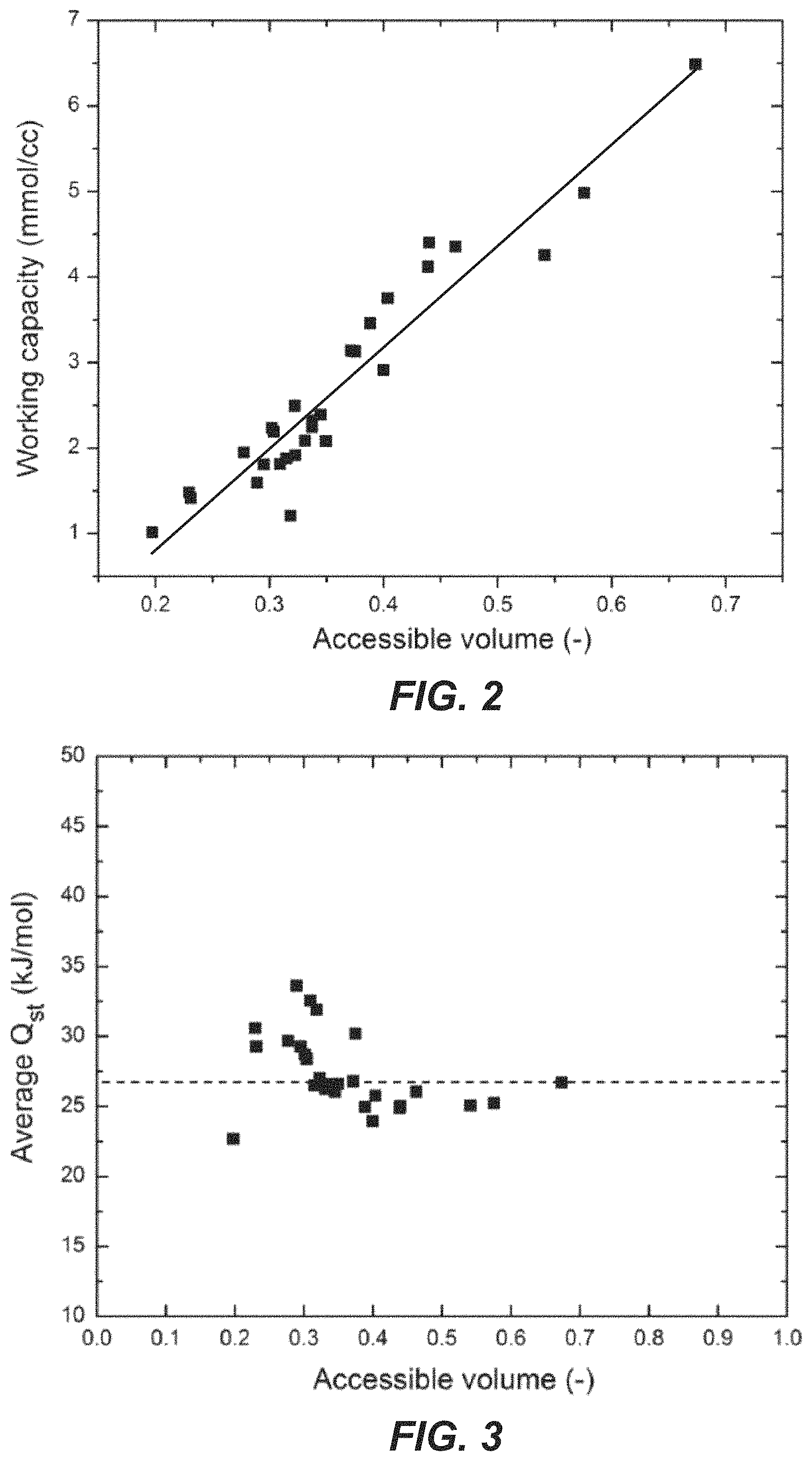
FIG. 2 illustrates a relationship between the working capacity and the accessible pore volume of adsorbents for a pressure swing adsorption (PSA) process.
FIG. 3 illustrates average heats of adsorption (Q.sub.st) at adsorption and desorption conditions for the optimal composition of each topology for the PSA process. The dashed line indicates the mean value of the average Q.sub.st for all optimal compositions.
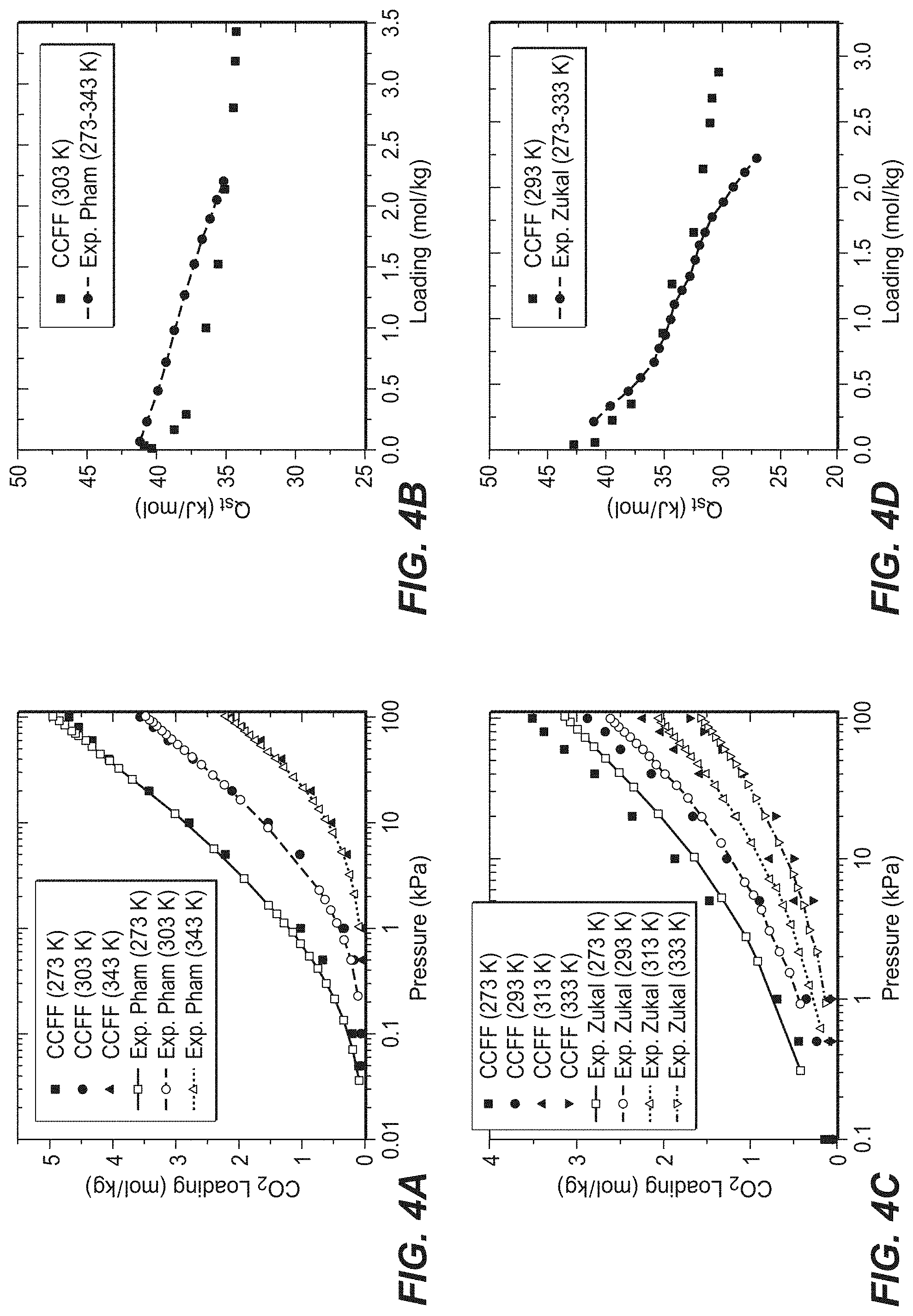
FIGS. 4(a)-(f) illustrate comparison of simulated and experimental adsorption properties of CO.sub.2 in K-exchanged and K/Na-exchanged zeolites as follows: (a) isotherms and (b) isosteric heats of adsorption in K-CHA (Si/Al=12), (c) isotherms and (d) isosteric heats of adsorption in K-MCM-22 (Si/Al=15), (e) isotherms in KX (Si/Al=1.23) and KY (Si/Al=2.37) at 298 K, and (f) isotherms in K/Na-LTA (Si/Al=1, 17.4% K). The experimental data are from Pham et al. (Pham, T. D.; Liu, Q. L.; Lobo, R. F. Langmuir 2013, 29, 832), Zukal et al. (Zukal, A.; Pawlesa, J.; Cejke, J. Adsorption 2009, 15, 264), Walton et al. (Walton, K. S.; Abney, M. B.; LeVan, M. D. Micropor Mesopor Mat 2006, 91, 78), and Liu et al. (Liu, Q. L.; Mace, A.; Bacsik, Z.; Sun, J. L.; Laaksonen, A.; Hedin, N. Chem Commun 2010, 46, 4502). Lines are drawn to guide the eye.
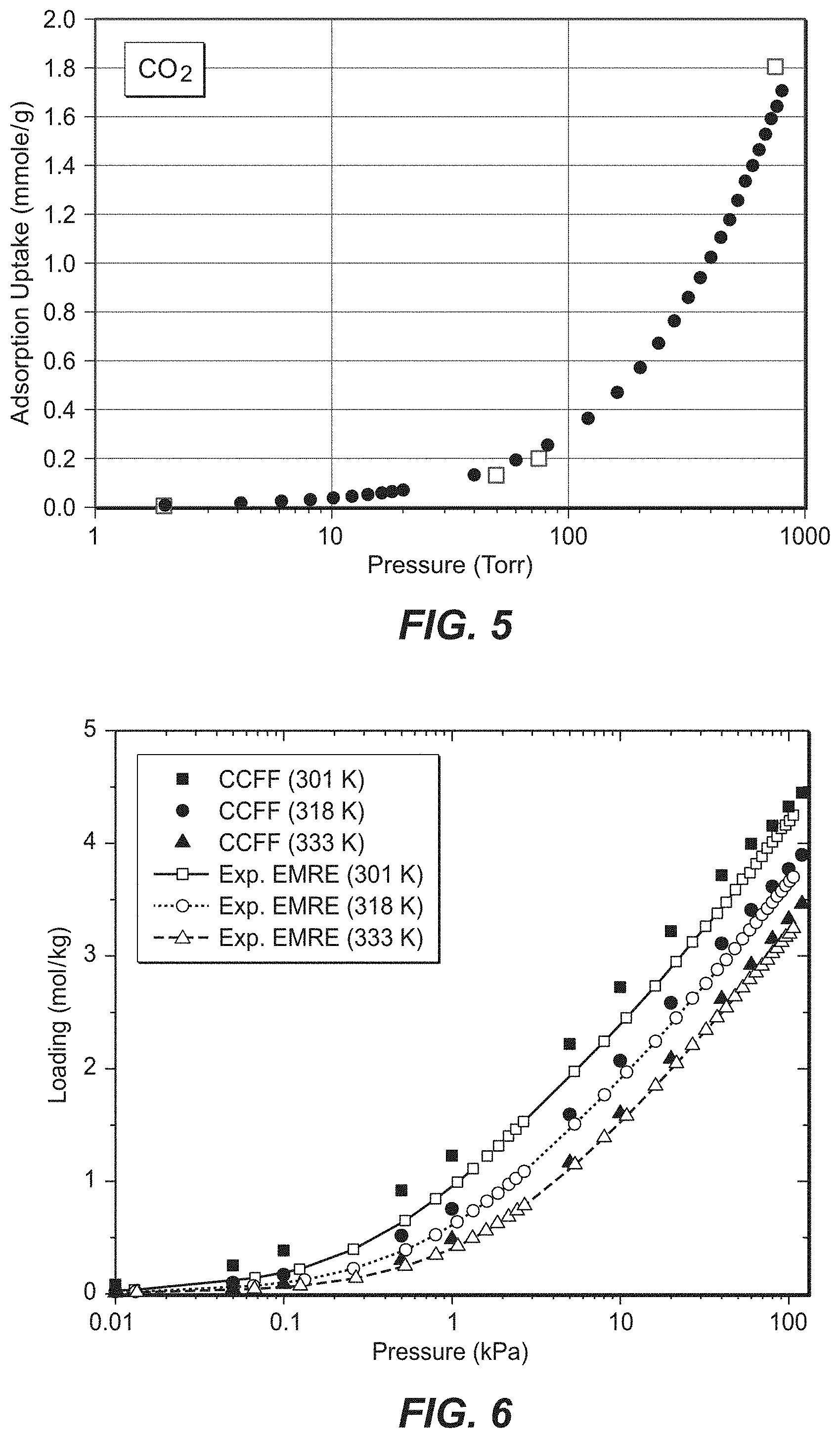
FIG. 5 illustrates a CO.sub.2 adsorption isotherm for SSZ-35 (circles) compared to the simulated CO.sub.2 adsorption (open squares).
FIG. 6 illustrates CO.sub.2 adsorption isotherms at different temperatures (open symbols) for SSZ-13 (circles) compared to the simulated CO.sub.2 adsorption isotherms (points).
FIG. 7 illustrates a CO.sub.2 adsorption isotherm for SSZ-16 (points) compared to the simulated CO.sub.2 adsorption (lines) at 28.degree. C. and 120.degree. C.
DETAILED DESCRIPTION
In various aspects of the invention, adsorbent materials, adsorbent contactors and gas separation processes using the adsorbent materials are provided.
I. Definitions
To facilitate an understanding of the present invention, a number of terms and phrases are defined below.
As used in the present disclosure and claims, the singular forms "a," "an," and "the" include plural forms unless the context clearly dictates otherwise.
Wherever embodiments are described herein with the language "comprising," otherwise analogous embodiments described in terms of "consisting of" and/or "consisting essentially of" are also provided.
The term "and/or" as used in a phrase such as "A and/or B" herein is intended to include "A and B", "A or B", "A", and "B".
As used herein, the term "adsorption" includes physisorption, chemisorption, and condensation onto a solid support, adsorption onto a solid supported liquid, chemisorption onto a solid supported liquid and combinations thereof.
As used herein, the term "breakthrough" refers to the point where the product gas leaving the adsorbent bed exceeds the target specification of the contaminant component. At the breakthrough point, the adsorbent bed can be considered "spent", such that any significant further operation through the spent adsorption bed alone will result in off-specification product gas. As used herein, the "breakthrough" can generally coincide with the "adsorption front", i.e., at the time breakthrough is detected at the outlet of the adsorbent bed, the adsorption front is generally located at the end of the adsorption bed.
As used herein, the term "selectivity" refers to a binary (pairwise) comparison of the molar concentration of components in the feed stream and the total number of moles of these components adsorbed by the particular adsorbent during the adsorption step of the process cycle under the specific system operating conditions and feedstream composition. For a feed containing component A, component B, as well as additional components, an adsorbent that has a greater "selectivity" for component A than component B will have at the end of the adsorption step of the swing adsorption process cycle a ratio: U.sub.A=(total moles of A in the adsorbent)/(molar concentration of A in the feed) that is greater than the ratio: U.sub.B=(total moles of B in the adsorbent)/(molar concentration of B in the feed) Where U.sub.A is the "Adsorption Uptake of component A" and U.sub.B is the "Adsorption Uptake of component B".
Therefore for an adsorbent having a selectivity for component A over component B that is greater than one: Selectivity=U.sub.A/U.sub.B (where U.sub.A>U.sub.B).
As used herein, the term "kinetic selectivity" refers to the ratio of single component diffusion coefficients, D (in m.sup.2/sec), for two different species. These single component diffusion coefficients are also known as the Stefan-Maxwell transport diffusion coefficients that are measured for a given adsorbent for a given pure gas component. Therefore, for example, the kinetic selectivity for a particular adsorbent for component A with respect to component B would be equal to D.sub.A/D.sub.B. The single component diffusion coefficients for a material can be determined by tests well known in the adsorptive materials art. The preferred way to measure the kinetic diffusion coefficient is with a frequency response technique described by Reyes et al. in "Frequency Modulation Methods for Diffusion and Adsorption Measurements in Porous Solids", J. Phys. Chem. B. 101, pages 614-622, 1997. In a kinetically controlled separation it is preferred that kinetic selectivity (i.e., D.sub.A/D.sub.B) of the selected adsorbent for the first component (e.g., Component A) with respect to the second component (e.g., Component B) be greater than 5, greater than 20, and particularly greater than 50.
As used herein, the term "equilibrium selectivity" is defined in terms of the slope of the single component uptake into the adsorbent (in .mu.mole/g) vs. pressure (in torr) in the linear portion, or "Henry's regime", of the uptake isotherm for a given adsorbent for a given pure component. The slope of this line is called herein the Henrys constant or "equilibrium uptake slope", or "H". The "equilibrium selectivity" is defined in terms of a binary (or pairwise) comparison of the Henrys constants of different components in the feed for a particular adsorbent. Therefore, for example, the equilibrium selectivity for a particular adsorbent for component A with respect to component B would be HA/HB. It is preferred that in an equilibrium controlled separation the equilibrium selectivity (i.e., HA/HB) of the selected adsorbent for the first component (e.g., Component A) with respect to the second component (e.g., Component B) be greater than 5, greater than 20, and particularly greater than 50.
As used herein, the term "Si/Al ratio" is defined as the molar ratio of silica to alumina of a zeolitic structure.
II. Methods of Designing Zeolite Materials for CO.sub.2 Adsorption
In a first embodiment, a method of designing a zeolite material for CO.sub.2 adsorption is provided. To describe adsorption of CO.sub.2 molecules in zeolites, the following three interactions need to be studied: 1) CO.sub.2-zeolite; 2) cation-framework structure; and 3) CO.sub.2--CO.sub.2. The EPM2 model (see Harris and Young, J. Phys. Chem., 1995, 99 12021) may be used to represent the CO.sub.2--CO.sub.2 interaction because the phase behavior of pure CO.sub.2 is correctly captured. For the CO.sub.2-zeolite and the cation-framework structure interactions, a first-principles-based force fields for crystalline porous materials approach may be used. Specifically, a fully periodic framework to represent adsorbent structure may be used and quantum chemistry calculations for numerous adsorption configurations randomly scattered throughout the whole framework may be made. This approach may be used for adsorption of CO.sub.2 in siliceous zeolites and also for cation exchanged zeolites (e.g., potassium cation, sodium cation, etc.). See Fang et al., J. Phys. Chem. C, 2012, 116, 10692; Fang et al., Phys Chem. Chem. Phys., 2013, 15, 12882. The developed force fields may accurately predict experimental adsorption properties and show transferability across different zeolite topologies. An example of first-principles-derived force field parameters are shown in Tables 1, 2 and 3 below.
TABLE-US-00001 TABLE 1 First-Principles-Derived Force Field Parameters For CO.sub.2 In K/Na-Exchanged Zeolites--Shown Are Lennard-Jones Potential Parameters And Partial Charges For Coulombic Interactions CCFF Cross Species .epsilon./k.sub.b (K) .sigma. ({acute over (.ANG.)}) Charge (e) Si--C 49.75 3.620 Si (2.21) Si--O 38.90 3.494 O.sub.z.sup.Si (-1.105) O.sub.z--C 29.12 3.193 O.sub.z.sup.Al (-1.32) O.sub.z--O 23.43 3.067 Al (2.08) Al--C 32.21 3.366 K (0.99) Al--O 25.32 3.246 Na (0.99) K--C 60.60 3.232 H (0.51) K--O 48.19 3.111 Na--C 66.78 2.827 Na--O 54.76 2.707 H--O 225.46 1.969 H--C 270.70 2.061
TABLE-US-00002 TABLE 2 Buckingham Parameters For K- And Na-Framework Interactions Cross Species A (eV) B ({acute over (.ANG.)}) C (eV) K--O.sub.z 5258.3 0.2916 193.7 Na--O.sub.z 3261.6 0.2597 45.4
TABLE-US-00003 TABLE 3 Morse Potential Parameters For H-Framework Interactions Cross Species P.sub.0/k.sub.B(K) p.sub.1 p.sub.2 ({acute over (.ANG.)}) H--O.sub.z.sup.Si 16113.4 6.3457 1.1239 H--O.sub.z.sup.Al 16113.4 6.3457 1.1239
Here Morse potential is defined as (Demiralp et al, Phys. Rev. Lett. 1999, 82, 1708): U=p.sub.0[e.sup.p.sup.1.sup.*(1-r/p.sup.2.sup.)-2e.sup.(p.sup.1.sup./2)*(- 1-r/p.sup.3.sup.)]
During molecular simulations of adsorption isotherms, framework atoms may be fixed and extra-framework cations may be allowed to move (see e.g. Fang et al., Phys Chem. Chem. Phys., 2013, 15, 12882). The positions of extra-framework cations can have a significant impact on the adsorption properties. For most cationic zeolites, however, the experimental information for cation locations is not available. To get more reliable cation distributions for each material, pre-equilibration simulations prior to the adsorption of CO.sub.2 may be performed. Parallel tempering (also known as canonical replica-exchange Monte Carlo) may be used in these simulations. For each cationic material, replicas (e.g., 9) may be included in simulations at temperatures, such as 300K, 390K, 507K, 659K, 857K, 1114K, 1448K, 1882K and 2447K, respectively. The lowest temperature may be room temperature, and the highest temperature should be high enough so as to ensure that no replicas become trapped in local energy minima. Reasonable degree of overlap between the potential energy distributions of neighboring state points was found.
Adsorption isotherms of CO.sub.2 in zeolites may be predicted computationally using standard Grand Canonical Monte Carlo (GCMC) methods. The chemical potential may be determined from the fugacity, and the fugacity coefficients may be computed using the Peng-Robinson equation of state (Peng and Robinson Ind. Eng. Chem. Fundam. 1976, 15, 59). Isosteric heats of adsorption, Q.sub.st, defined as the difference in the partial molar enthalpy of the adsorption between the gas phase and the adsorbed phase, may be determined. Some topologies, for example, FAU and LTA, include regions such as sodalite cages that are inaccessible for CO.sub.2 molecules. These regions may be blocked in the simulations to avoid spurious adsorption of CO.sub.2 in these regions.
Accessible pore volume, which is defined as the percentage of the pore volume to the total volume of the zeolite, may be computed from Widom particle insertion using Helium. For the calculations of pore volumes, the Clay Force Field (CLAYFF) may be used for the atoms of the zeolite and force field parameters from the previous work may be used for He--He interactions (See Cygan et al., J. Phys. Chem. B, 2004, 108, 1255; Talu et al. Colloids and Surfaces a-Physicochemical and Engineering Aspects, 2001, 187, 83). Lorentz-Berthelot mixing rules may be applied for the cross species interactions.
Prototypical processes may be defined for CO.sub.2 capture. For example, the following processes such as in Table 3 may be modeled. It understood that CO.sub.2 adsorption processes are not limited to processes considered in Table 4.
TABLE-US-00004 TABLE 4 Processes Considered Adsorption Desorption Processes T (K) P (bar) T (K) P (bar) PSA1 300 5 300 1 PSA2 300 20 300 1 PSA3 300 0.066 300 0.0026 PSA4 233 0.066 233 0.0026 PTSA1 300 5 373 1 PTSA2 300 20 373 1 VSA 300 1 300 0.1 VTSA1 300 1 373 0.1 VTSA2 300 1 473 0.2 VTSA3 300 5 473 0.2 TSA 300 1 473 1
The choice of adsorption and desorption conditions may vary and be based on previous research and industrial relevance. The conditions in Table 3 are representative of only several possible set of conditions. Detailed process modeling of gas capture may require a description of multi-component adsorption of the gas mixtures of interest. As a first step, it may be sufficient to focus simply on the capacity a material has for the primary component of interest (e.g., CO.sub.2). For example, zeolites as potential adsorbents for CO.sub.2 may be considered based on single-component adsorption of CO.sub.2.
For each process the working capacity (.DELTA.N), which is defined as the difference between the adsorbed amounts of CO.sub.2 at the adsorption (N.sub.ads) and desorption (N.sub.des) conditions, may be used to evaluate adsorption performance of the materials. Thus, via molecular simulations using the first-principles-derived force fields, the relationship between CO.sub.2 working capacity and Si/Al ratio and cation concentration (e.g., sodium cation, potassium cation) may be determined for each zeolite framework structure at each defined process condition. For each framework structure, the optimal composition may be determined for each specified process. The optimal compositions for selected processes in Table 4 are shown below in Table 5.
TABLE-US-00005 TABLE 5 Examples Of Working Capacity Of The Optimal Compositions For Selected Zeolite Topologies In The Four CO.sub.2 Adsorption Processes PSA1 VSA PTSA1 VTSA1 .DELTA.N .DELTA.N .DELTA.N .DELTA.N (mmol/ (mmol/ (mmol/ (mmol/ Zeolite cc) Zeolite cc) Zeolite cc) Zeolite cc) RWY_5_100 6.49 RWY_3_17 5.34 RWY_3_17 11.17 IRY_2_0 8.78 IRY_10_100 4.98 IRY_3_83 4.48 IRY_3_0 8.68 IRR_2_0 7.82 FAU_50_67 4.40 FAU_5_100 4.28 IRR_5_50 7.76 FAU_2_33 7.51 TSC_50_83 4.36 IRR_3_100 3.79 FAU_5_83 7.12 EMT_2_0 7.26 IRR_10_100 4.25 EMT_5_83 3.78 TSC_10_17 6.87 RWY_3_17 7.14 EMT_50_100 4.12 VFI_1_0 3.52 EMT_5_33 6.74 TSC_1_0 6.60 LTA_50_67 3.75 RRO_Si 3.43 VFI_1_0 6.38 LTA_1_0 5.93 VFI_10_100 3.46 DAC_Si 3.39 LTA_10_33 5.87 VFI_2_0 5.31 SFF_Si 3.14 LTA_5_50 3.30 STF_Si 5.50 STF_5_0 5.24 STF_Si 3.13 TSC_5_0 3.27 DAC_Si 5.42 SFF_3_0 5.05 MWW_Si 2.91 STF_50_100 3.13 RRO_Si 5.06 MWW_2_33 4.87 ITH_Si 2.50 HEU_Si 2.84 SFF_50_100 4.94 STI_2_0 4.82 NES_Si 2.39 MWW_10_100 2.72 MWW_25_100 4.90 DAC_50_17 4.75 TUN_Si 2.32 SFF_25_67 2.69 ITH_Si 4.22 RRO_10_83 4.57 TER_Si 2.24 TER_50_100 2.31 TER_Si 4.20 NES_2_0 4.47 FER_Si 2.23 STI_10_83 2.29 STI_10_100 4.18 HEU_25_17 4.11 MFS_Si 2.19 MFS_25_100 2.25 NES_50_100 4.15 MFS_10_17 4.04 IMF_Si 2.09 TUN_50_100 2.23 TUN_Si 4.10 FER_10_33 3.79 STI_Si 2.08 NES_10_67 2.22 HEU_Si 4.07 SZR_5_67 3.77 SZR_Si 1.95 FER_50_100 2.18 FER_Si 4.05 EUO_3_0 3.77 MFI_Si 1.92 ITH_25_100 2.17 MFS_Si 3.97 ITH_10_17 3.74 EUO_Si 1.88 LAU_Si 2.15 LAU_Si 3.81 TER_10_17 3.66 DAC_Si 1.81 MFI_50_100 2.13 MFI_Si 3.79 TUN_10_67 3.60 LAU_Si 1.81 SZR_50_83 2.05 SZR_Si 3.78 LAU_10_0 3.44 RRO_Si 1.59 EUO_25_100 1.98 IMF_Si 3.78 MFI_10_33 3.34 TON_Si 1.48 IMF_50_100 1.96 EUO_25_100 3.58 IMF_10_0 3.28 MTT_Si 1.41 TON_Si 1.95 TON_Si 3.32 MTT_10_83 2.60 HEU_50_100 1.21 MTT_Si 1.59 MTT_Si 2.89 TON_25_0 2.46 .sup.aTo describe the materials, we use ZEO_A_B to represent cationic zeolites, where ZEO indicates the topology type, A the Si/Al ratio, and B the percentage concentration of K cations. For siliceous zeolites, we use ZEO_Si.
The zeolite materials described herein may be represented by the following formula ZEO_A_B, wherein "ZEO" represents the framework structure, "A" represents the Si/Al ratio and "B" represents the concentration of potassium cations. For example, MFI_10_50 represents a zeolite material having an MFI framework structure, a Si/Al ratio of 10 and a potassium cation concentration of 50%. MFI_Si represents a zeolite material having an MFI framework structure that is highly siliceous. As used herein, "highly siliceous" refers to a zeolite material having a Si/Al ratio of .gtoreq.about 100, .gtoreq.about 150, .gtoreq.about 200, .gtoreq.about 250, .gtoreq.about 300, .gtoreq.about 350, .gtoreq.about 400.gtoreq.about 450, .gtoreq.about 500, .gtoreq.about 550, .gtoreq.about 600, .gtoreq.about 650, .gtoreq.about 700, .gtoreq.about 750, .gtoreq.about 800, .gtoreq.about 850, .gtoreq.about 900, .gtoreq.about 950, or .gtoreq.about 1000. In particular, a highly siliceous zeolite has a Si/Al ratio of above 100. Such highly siliceous zeolites may include a cation concentration of less than about 10%, less than about 5%, less than about 1%, less than about 0.1%, or about 0%.
Also, it has been found that a substantially linear relationship between working capacity and accessible pore volume exists for the optimal compositions of the framework structures for the processes studied, as shown in FIG. 2 for the PSA1 process. It was further found that the average Q.sub.st are located within a narrow range for each process, as shown in FIG. 3 for the PSA1 process. In contrast, the heats of adsorption at zero coverage (Q.sub.st.sup.0) are located in a relatively larger range for each process. The results indicated that suitable average Q.sub.st are required for maximizing the working capacity of each topology in a specified process. Too high an average Q.sub.st may lead to a large amount of residual adsorbed adsorbate at the desorption pressure, and therefore to a reduced working capacity, whereas too low an average Q.sub.st may also result in a low working capacity. As a result, for each topology there is an optimal average Q.sub.st for obtaining the maximum working capacity.
Thus, in various aspects, a method of designing zeolites for CO.sub.2 adsorption involves identifying a target adsorption process for CO.sub.2. Any suitable CO.sub.2 adsorption process known in the art may be targeted. Non-limiting examples of suitable CO.sub.2 adsorption processes include pressure swing adsorption (PSA), temperature swing adsorption (TSA), pressure temperature swing adsorption (PTSA), vacuum swing adsorption (VSA), vacuum temperature swing adsorption (VTSA), partial pressure swing adsorption (PPSA), partial pressure temperature swing adsorption (PPTSA), and displacement desorption swing adsorption (DDSA), and any other combinations thereof. Once the CO.sub.2 adsorption process is identified, zeolite framework structure may be selected. In particular, zeolite framework structures with large accessible pore volumes from 0.15 and higher may be selected. Examples of suitable zeolite framework structures include but are not limited to AFT, AFX, CAS, CHA, DAC, EMT, EUO, FAU, FER, HEU, IMF, IRR, IRY, ITH, ITT, KFI, LAU, LTA, MFI, MFS, MRE, MTT, MWW, NES, PAU, RHO, RRO, RWY, SFF, STF, STI, SZR, TER, TON, TSC, TUN, UFI, and VFI. A person of ordinary skill in the art knows how to make the zeolites having an aforementioned framework structure. For example, see the references provided in the International Zeolite Association's database of zeolite structures found at www.iza-structure.org/databases.
Following selection of a zeolite framework, the Si/Al ratio may be adjusted in order to arrive at a heat of adsorption (Q.sub.st) that results in a high CO.sub.2 working capacity (.DELTA.N) for zeolite material in the identified CO.sub.2 adsorption process. As used herein, a "high working capacity" or "high AN" may be .gtoreq.about 1.0 mmol/cc, .gtoreq.about 2.0 mmol/cc, .gtoreq.about 3.0 mmol/cc, .gtoreq.about 4.0 mmol/cc, .gtoreq.about 5.0 mmol/cc, .gtoreq.about 6.0 mmol/cc, .gtoreq.about 7.0 mmol/cc, .gtoreq.about 8.0 mmol/cc, .gtoreq.about 9.0 mmol/cc, .gtoreq.about 10.0 mmol/cc, .gtoreq.about 11.0 mmol/cc, .gtoreq.about 12.0 mmol/cc, .gtoreq.about 13.0 mmol/cc, .gtoreq.about 14.0 mmol/cc, .gtoreq.about 15.0 mmol/cc, .gtoreq.about 16.0 mmol/cc, .gtoreq.about 17.0 mmol/cc, .gtoreq.about 18.0 mmol/cc, .gtoreq.about 19.0 mmol/cc, or .gtoreq.about 20.0 mmol/cc. Examples of suitable Si/Al ratios include, but are not limited to about 1, about 2, about 3, about 5, about 9, about 10, about 15, about 20, about 25, about 30, about 35, about 40, about 45, about 50, about 55, about 60, about 65, about 70, about 75, about 80, about 85, about 90, about 95, or about 100. Ranges expressly disclosed include combinations of the above-enumerated values, e.g., about 1 to about 100, about 3 to about 100, about 1 to about 75, about 1 to about 20, about 1 to about 10, about 9 to about 85, about 9 to about 70, about 5 to about 45, about 40 to about 60, about 3 to about 100, about 3 to about 75, about 5 to about 60, about 3 to about 60, about 3 to about 30, etc.
Additionally, cations may be introduced into the zeolite material at varying concentrations to arrive at a high CO.sub.2 working capacity for the zeolite material. The concentration of cations is the percentage of specific cations to the total number of positively charged extra framework cations and protons, which are required to balance the charge in the specific zeolite framework. Examples of suitable cations include, but are not limited to potassium cations (K.sup.+), sodium cations (Na.sup.+), lithium cations (Li.sup.+), cesium cations (Cs.sup.+), rubidium cations (Rb.sup.+), silver cations (Ag.sup.+), calcium cations (Ca.sup.2+), magnesium cations (Mg.sup.2+), barium cations (Ba.sup.2+), strontium cations (Sr.sup.2+), copper cations (Cu.sup.2+), and protons (H.sup.+). For example, the zeolite material may have a cation (e.g., potassium cation, sodium cation) concentration of .gtoreq.about 0.0%, .gtoreq.about 5.0%, .gtoreq.about 10.0%, .gtoreq.about 15.0%, .gtoreq.about 16.7%, .gtoreq.about 20.0%, .gtoreq.about 25.0%, .gtoreq.about 30.0%, .gtoreq.about 33.4%, .gtoreq.about 35.0%, .gtoreq.about 40.0%, .gtoreq.about 45.0%, .gtoreq.about 50.0%, .gtoreq.about 55.0%, .gtoreq.about 60.0%, .gtoreq.about 65.0%, .gtoreq.about 66.7%, .gtoreq.about 70.0%, .gtoreq.about 75.0%, .gtoreq.about 80.0%, .gtoreq.about 83.3%, .gtoreq.about 85.0%, .gtoreq.about 90.0%, .gtoreq.about 95.0%, or about 100%. Ranges expressly disclosed include combinations of the above-enumerated values, e.g., about 0.0% to about 100%, about 1.0% to about 100%, about 5.0% to about 100%, about 10% to about 100%, about 0.0% to about 90.0%, about 0.0% to about 40.0%, about 40.0% to about 100%, about 0% to about 50%, about 5% to about 40%, etc. In particular, the Si/Al ratio may be adjusted in the zeolite material before the introduction of cations. Once the desired zeolite material is designed, experimental testing may be undergone on the zeolite material where other factors, such as energy costs for adsorbent regeneration, adsorption kinetics, etc., may be considered.
III. CO.sub.2 Adsorption Processes
In another embodiment, a CO.sub.2 adsorption process is provided herein. The CO.sub.2 adsorption process comprises contacting a gas mixture containing CO.sub.2 with an adsorbent material, wherein the adsorbent material may be designed according to the description above.
In various aspects, the CO.sub.2 adsorption process can be achieved by swing adsorption processes, such as pressure swing adsorption (PSA) and temperature swing adsorption (TSA) and combinations thereof (e.g., pressure temperature swing adsorption (PTSA)). All swing adsorption processes have an adsorption step in which a feed mixture (typically in the gas phase) is flowed over an adsorbent that preferentially adsorbs a more readily adsorbed component relative to a less readily adsorbed component. A component may be more readily adsorbed because of kinetic or equilibrium properties of the adsorbent material.
PSA processes rely on the fact that gases under pressure tend to be adsorbed within the pore structure of the adsorbent materials. Typically, the higher the pressure, the greater the amount of targeted gas component that will be adsorbed. When the pressure is reduced, the adsorbed targeted component is typically released, or desorbed. PSA processes can operate across varying pressures. For example, a PSA process that operates at pressures below atmospheric pressure is a vacuum swing adsorption (VSA) process. PSA processes can be used to separate gases of a gas mixture, because different gases tend to fill the pores or free volume of the adsorbent to different extents due to either the equilibrium or kinetic properties of the adsorbent. In many important applications, to be described as "equilibrium-controlled" processes, the adsorptive selectivity is primarily based upon differential equilibrium uptake of the first and second components. In another important class of applications, to be described as "kinetic-controlled" processes, the adsorptive selectivity is primarily based upon the differential rates of uptake of the first and second components.
TSA processes also rely on the fact that gases under pressure tend to be adsorbed within the pore structure of the adsorbent materials. When the temperature of the adsorbent is increased, the adsorbed gas is typically released, or desorbed. By cyclically swinging the temperature of adsorbent beds, TSA processes can be used to separate gases in a mixture when used with an adsorbent selective for one or more of the components in a gas mixture. Partial pressure purge displacement (PPSA) swing adsorption processes regenerate the adsorbent with a purge. Rapid cycle (RC) swing adsorption processes complete the adsorption step of a swing adsorption process in a short amount of time. For kinetically selective adsorbents, it can be preferable to use a rapid cycle swing adsorption process. If the cycle time becomes too long, the kinetic selectivity can be lost. These swing adsorption protocols can be performed separately or in combinations. Examples of processes that can be used herein either separately or in combination are PSA, TSA, PTSA, VSA, VTSA, PPSA, PPTSA DDSA.
Additionally or alternatively, the processes of the present invention can comprise an adsorption step in which the preferentially adsorbed components (e.g., CO.sub.2) of the feed mixture can be adsorbed by the adsorbent material described herein as contained in an adsorbent contactor, such as an adsorbent bed, while recovering the less preferentially adsorbed components at the product end of the adsorbent bed at process pressures. The adsorption step may be performed at a first pressure such that the partial pressure of CO.sub.2 is from about 0.5 bar to about 25 bar, particularly about 3 bar to about 25 bar, particularly about 15 bar to about 25 bar, particularly about 3 bar to about 10 bar, particularly about 0.5 bar to about 7 bar, or particularly about 0.5 bar to about 3 bar. Additionally or alternatively, the adsorption step of the present invention can be performed at a first temperature from about -20.degree. C. to about 80.degree. C., particularly from about 0.degree. C. to about 50.degree. C. or particularly from 10.degree. C. to 30.degree. C. Additionally or alternatively, heat of adsorption can be managed by incorporating a thermal mass into the adsorption bed to mitigate the temperature rise occurring during the adsorption step. The temperature rise from the heat of adsorption can additionally or alternately be managed in a variety of ways, such as by flowing a cooling fluid through the passages external to the adsorbent bed (i.e., the passages that are used to heat and cool the contactor).
Additionally or alternatively, the passages external to the adsorbent bed can be filled with a fluid that is not flowing during the adsorption process. In this case, the heat capacity of the fluid can serve to mitigate the temperature rise in the adsorbent bed. Combinations of some or all of these heat management strategies can be employed. Even with these heat management strategies, during this step, the final temperature of the bed can typically be slightly higher than the feed inlet temperature. Particularly, the degree of adsorption and cooling can be managed so that the maximum temperature rise at any point within the contactor can be less than about 40.degree. C., e.g., less than about 20.degree. C., less than about 10.degree. C., or less than about 5.degree. C. During adsorption, the strongest-adsorbing components can tend to attach most strongly to the adsorbent and can thus be least mobile. Such strongest-adsorbing components can thus tend to occupy regions of adsorbent closest to the inlet and can generally displace weakly adsorbed components from those regions.
Over the period of adsorption, the adsorbates can tend to order themselves from strongest to weakest, moving from inlet to outlet of the adsorption channels of the contactor. In preferred embodiments, the feed gas velocity can be chosen so that a relatively sharp concentration front moves through the contactor, i.e., such that the concentration gradient of adsorbate(s) extends over a relatively short distance, taking into consideration the absolute amplitude of the gradient.
The adsorption step can be stopped at a predetermined point before the adsorption front breaks through the product output end of the adsorbent bed. The adsorption front can move at least 30% of the way down the bed, e.g., at least 50% or at least 80%, before the adsorption step is stopped. Additionally or alternatively, the adsorption step can be conducted for a fixed period of time set by the feed flow rate and adsorbent capacity. Further additionally or alternatively, the adsorption step can be conducted for a time less than 600 seconds, particularly less than 120 seconds, e.g., less than 40 seconds or less than 10 seconds, or less than 5 seconds. In some instances, the adsorption front can be allowed to break through the output end only for a short duration (e.g., for at most a few seconds), but usually the adsorption front is not allowed to break through, which can maximize utilization of the bed.
After the adsorption step, the feed gas channels in the contactor can optionally be depressurized to a second pressure lower than the first pressure. For example, the second pressure may be such that the partial pressure of CO.sub.2 is from about 0.5 bar to about 2 bar, particularly about 0.05 bar to about 0.5 bar, particularly about 0.08 bar to about 0.3 bar, or particularly about 0.09 bar to about 0.4 bar. Reduction in pressure to a second pressure may be achieved by passing a purge gas, substantially free of target gas species (e.g., CO.sub.2) through adsorbent bed. The purge gas may comprise an inert gas, such as nitrogen.
Additionally or alternatively, the feed input end of the adsorbent bed can be sealed with respect to the passage of a gas, and heat can be externally applied to the adsorbent bed. By "externally heated" it is meant that heat is not applied directly to the adsorbent bed through the flow channels through which the feed gas mixture had flowed and into which the target gas component will be desorbed. The heat can be delivered to the adsorbent bed through a plurality of heating/cooling channels in thermal communication, but not in fluid communication, with the feed gas flow channels of the adsorbent. The adsorbent bed can be externally heated co-currently or counter-currently along its length with respect to the flow of the feed gas mixture, or in a combination of co-current and counter-current heating steps. The flow channels that will carry heating and cooling fluid can be in physical contact with the adsorbent bed to enhance heat transfer. The adsorbent bed can be heated to a second temperature higher than the first temperature used during the adsorption step, the second temperature at least about 10.degree. C. higher than the first temperature, e.g., at least about 20.degree. C. higher, at least about 40.degree. C. higher, at least about 75.degree. C. higher, at least about 90.degree. C. higher, at least about 100.degree. C. higher, at least about 125.degree. C. higher, at least about 150.degree. C. higher, at least about 175.degree. C. higher or at least about 200.degree. C. higher; additionally or alternatively, the second temperature can be from about 50.degree. C. to about 250.degree. C., e.g., from about 150.degree. C. to 250.degree. C., from about 50.degree. C. to about 150.degree. C., from about 75.degree. C. to about 125.degree. C. or from about 175.degree. C. to about 225.degree. C.
During the heating step, the gas pressure in the channel can tend to rise. To improve regeneration at the product end of the bed, during the heating step, the bed can advantageously be slowly purged with clean gas from the clean end (product end) of the adsorbent bed to the point of product recovery. By "clean gas" it is meant that a gas is substantially free of target gas components. For example, if the target gas is CO.sub.2, then the clean gas will be a stream substantially CO.sub.2. In one embodiment, clean gas will contain less than 5 mol % CO.sub.2, and particularly less than 1 mol % of CO.sub.2. An example of a suitable clean gas would be the product gas itself. When the current invention is utilized for the removal of CO.sub.2 from a natural gas stream, in one embodiment, the "clean gas" is comprised of at least one of the hydrocarbon product streams, and in another embodiment is comprised of C.sub.3-hydrocarbons, and in another embodiment is comprised of methane. In other embodiments, a separate "clean gas" can be used. In one of these embodiments, the "clean gas" is comprised of nitrogen.
The purge can be introduced at a pressure higher than the pressure in the adsorbent bed. It can be preferred for the total number of moles of purge gas introduced to be less that the number of moles of molecules adsorbed in the contactor, e.g., less than 25% or less that 10% of the number of moles adsorbed. By preventing the adsorption front from breaking through, the product end of the bed can be kept substantially free of the strongly-adsorbed species and can advantageously contain predominantly product species. The isotherms of the adsorbed target component can determine the partial pressure of the preferentially adsorbed component in equilibrium, with the new loading at the higher temperature. This partial pressure can, in some cases, be in excess of 40% greater than the feed pressure, or as much as 70% higher or more. Additionally or alternatively to the recovered sensible heat, a small amount of extra heat may be required to heat the bed to the final predetermined temperature. The isotherm can describe the amount of loading (mmol of adsorbed species per gram of adsorbent) for both chemisorption and physisorption processes.
The external heating can be conducted such that a thermal wave is used to pass heat through the contactor, as it transitions from the adsorption step to the regeneration step, in transitioning from the regeneration to adsorption step, in at least part of the regeneration step, and/or in at least part of the adsorption step. Similarly, it can be preferred to utilize a thermal wave in the cooling step. A thermal wave is a relatively sharp temperature gradient, or front, that can move linearly (i.e., approximately in a single direction within the contactor) during at least one step in the thermal swing adsorption/desorption cycle. The speed at which the thermal front (i.e., region with sharp temperature gradient) can move is referred to as the thermal wave velocity. The thermal wave velocity need not be constant, and the thermal wave direction need not be the same in both adsorption and regeneration steps. For example, the wave can move co-currently, counter-currently, or cross-flow in the adsorption and/or regeneration steps. It is also possible to design a process in which there is no significant thermal wave present in the adsorption step while there is a significant thermal wave in the regeneration step. The presence of a thermal wave in at least some portion of the thermal swing adsorption/regeneration cycle can enable the overall system to achieve a goal of substantially recuperating and recovering the heat required to temperature-swing the adsorbent bed. This, in turn, can improve process efficiency and/or can enable the use of high desorption temperatures that would not normally be considered for TSA operation.
Additionally or alternatively, the contactor is combined with the adsorbent material into a heat exchange structure in a manner that can produce a thermal wave. In Thermal Wave Adsorption (TWA), adsorbent can be placed in one set of heat exchanger channels, while the other set of channels can be used to bring heat into and/or take heat out of the adsorbent device. Fluids and/or gases flowing in the adsorbent and heating/cooling channels do not generally contact each other. The heat adding/removing channels can be designed and operated in a manner that results in a relatively sharp temperature wave in both the adsorbent and in the heating and cooling fluids during the heating and cooling steps in the cycle. An example of a contactor that can produce a relatively sharp thermal wave is a contactor as described herein.
Relatively sharp thermal waves, as used herein, can be expressed in terms of a standard temperature differential over a distance relative to the length of the mass/heat transfer flow in the apparatus. With respect to the mass/heat transfer, we can define a maximum temperature, T.sub.max, and a minimum temperature, T.sub.min, as well as convenient temperatures about 10% above T.sub.min (T.sub.10) and about 10% below T.sub.max (T.sub.90). Thermal waves can be said to be relatively sharp when at least the temperature differential of (T.sub.90-T.sub.10) occurs over at most 50% (e.g., at most 40%, at most 30%, or at most 25%) of the length of the apparatus that participates in the mass/thermal transfer. Additionally or alternatively, relative sharp thermal waves can be expressed in terms of a maximum Peclet number, Pe, defined to compare axial velocity of the heating/cooling fluid to diffusive thermal transport roughly perpendicular to the direction of fluid flow. Pe can be defined as (U*L)/.alpha., where U represents the velocity of the heating/cooling fluid (in m/s), L represents a characteristic distance over which heat is transported (to warm/cool the adsorbent) in a direction roughly perpendicular to the fluid flow, and a represents the effective thermal diffusivity of the contactor (in m.sup.2/s) over the distance L. In addition or alternately to the thermal differential over length, thermal waves can be said to be relatively sharp when Pe is less than 10, for example less than 1 or less than 0.1. To minimize time for heating/cooling of the contactor with little or no damage to the flow channel, it can be preferred for U to be in a range from about 0.01 m/s to about 100 m/s, e.g., from about 0.1 m/s to about 50 m/s or from about 1 m/s to about 40 m/s. Additionally or alternatively, to minimize size and energy requirements, it can be preferred for L to be less than 0.1 meter, e.g., less than 0.01 meter or less than 0.001 meter.
Thermal waves in such contactors can be produced when the heating and cooling fluids are flowed co-current or counter-current to the direction of the feed flow in the adsorption step. In many cases, it can be preferred not to have a significant flow of heating or cooling fluids during the adsorption step. A more comprehensive description of Thermal Wave Adsorption (TWA) and other appropriate contactor structures can be found, e.g., in U.S. Pat. No. 7,938,886, which is incorporated herein by reference. This reference shows how to design and operate a contactor to control the sharpness and nature of a thermal wave. A key operational parameter can include the fluid velocity in the contactor. Key design parameters can include the mass of the contactor and heat capacity and thermal conductivity of materials used to form the contactor and heat transfer fluid. An additional key design objective for the contactor can be finding one or more ways to reduce/minimize the distance over which heat has to be transferred, which is why relatively sharp thermal waves can be so desirable.
Additionally or alternatively, during the heating step, the volume of fluid at a temperature no more than 10.degree. C. warmer than the end of the contactor from which it is produced can represent at least 25% (e.g., at least 50% or at least 75%) of the volume of the fluid introduced into the contactor for heating. Similarly, when the present invention is operated to attain a thermal wave, it can be preferred that, during the cooling step, a cold fluid (such as pressurized water) can be flowed into the contactor and a hot fluid near the temperature of the contactor at the end of the recovery step can flow out of the contactor. Most of the recovery step can generally occur after the contactor has been heated. Thus additionally or alternatively during the cooling step, the volume of fluid at a temperature no more than 10.degree. C. colder than the end of the contactor from which it is produced can represent at least 25% (e.g., at least 50% or at least 75%) of the volume of the fluid introduced into the contactor for cooling.
One way to efficiently utilize thermal waves in the apparatuses according to the invention can be for heat recovery. The recovered energy can be used to reduce the energy requirements for heating and cooling of the contactor, for a different contactor of a multitude of contactors needed for a continuous process, and/or for any other purpose. More specifically, energy contained in the hot stream exiting the contactor during the cooling step can be utilized to reduce the energy that must be supplied during the heating step. Similarly, the cold stream exiting the contactor during the heating step can be utilized to reduce the energy that must be supplied to cool fluid to be supplied to the contactor during the cooling step. There are many ways to recoup the energy. For example, the hot thermal fluid flowing out of one contactor can be sent to another with trim heating in between, and/or the cold fluid flowing out of one contactor can be sent to another with trim cooling in between. The thermal fluid flow path between contactors can be determined by valves timed to route thermal fluid between contactors at appropriate points in the overall swing adsorption cycle. In embodiments where thermal fluid flows between contactors, it may also pass through a heat exchanger that adds or removes heat from the flowing thermal fluid and/or pass through a device, such as a compressor, pump, and/or blower, that pressurizes it so it can flow at the desired rate though the contactors. A heat storage medium can be configured so that the energy from the thermal wave moving through one contactor can be stored. A non-limiting example is a tank system that separately stores hot and cold fluids, which can each be fed back into the contactor that produced it and/or to another contactor. In many embodiments, the flow of the thermal fluid through the contactor can be arranged to minimize the mixing of the fluid in the direction of the general flow of the fluid through the contactor and to minimize the effect of the thermal conductivity of the fluid on the sharpness of the temperature wave.
Where energy is recovered, the recovered energy can be used to reduce the amount of sensible heat that must be supplied to heat and cool the contactor. The sensible heat is determined by the heat capacity and temperature rise (or fall) of the contactor. In some embodiments, at least 60% (e.g., at least 80% or at least 95%) of the sensible heat required for heating the contactor is recouped, and/or at least 60% (e.g., at least 80% or at least 95%) of the sensible heat needed to cool the contactor is recouped.
This external heating of the partially sealed adsorbent bed will result in at least a portion of the target species being desorbed from the adsorbent bed. It can also result in an increase in pressure of the resulting target species component stream. At least a portion of the desorbed target species component is recovered at pressures higher than that at the initiation of the heating step. That is, recovery of target gas will take place toward the end of the heating step with minimum or no depressurization of the adsorbent bed. It is preferred that the pressure be a least 2 bar, particularly at least 5 bar higher than that at the initiation of the heating step.
The pressure in the adsorbent bed is then reduced, particularly in a series of blow-down steps in a co-current or counter-current and can be performed with or without a purge gas stream to the final target gas recovery pressure. Pressure reduction can occur in less than 8 steps, particularly in less than 4 steps, with target species being recovered in each step. In one embodiment, the pressure is decreased by a factor of approximately three in each step. It is also preferred that the depressurization be conducted counter-currently and that during the depressurizing step a purge gas be passed counter-current (from product end to feed end) through the adsorbent bed. It is also preferred that the purge gas be a so-called clean gas as previously described.
In another embodiment, in any step, other than the adsorption step, the clean gas is conducted counter-currently through the adsorbent bed to ensure that the end of the bed is substantially free of target species. In another embodiment, the clean gas is conducted counter-currently through the adsorbent bed in at least a portion of the desorption steps. An effective rate of counter-current flowing clean gas is preferred during these step(s) to overcome mass diffusion to ensure that the product end of the bed is kept substantially free of the target species.
After the target gas has been recovered, the adsorbent bed can be cooled and repressurized. One can cool the bed before repressurization. The adsorbent bed can be cooled, particularly to a temperature that is no more than 40.degree. C. above the temperature of feed gas mixture, e.g., no more than 20.degree. C. above or no more than 10.degree. C. above. Additionally or alternatively, the adsorbent bed can be cooled by external cooling in a co-current or counter-current manner, such that a thermal wave can pass through the bed. In some such embodiments, the first part of the adsorbent bed can be cooled then repressurized. In certain of those embodiments, less than 90% of the length of adsorption bed can be cooled, e.g., less than 50%. The adsorbent bed can additionally or alternatively be purged with a clean gas during cooling.
The adsorbent bed can then be repressurized, during and/or after the cooling step, e.g., using clean product gas or counter-currently with blow-down gas from another bed after a first stage of repressurization. The final pressure of the repressurization step can be substantially equal to the pressure of the incoming feed gas mixture.
The adsorbent be can be in the form of open flow channels, e.g., parallel channel connectors, in which the majority of the open pore volume is attributable to microporous pore diameters, e.g., in which less than 40%, particularly less than 20%, for example less than 15% or less than 10%, of its open pore volume can originate from pore diameters greater than 20 angstroms (and less than about 1 micron; i.e., from mesoporous and macroporous pore diameters).
A flow channel is described herein as that portion of the contactor in which gas flows if a steady state pressure difference is applied between the point/place at which a feed stream enters the contactor and the point/place a product stream leaves the contactor. By "open pore volume" herein, it is meant all of the open pore space not occupied in the volume encompassed by the adsorbent material. The open pore volume includes all open spaces in the volume encompassed by the adsorbent material, including but not limited to all volumes within the adsorbent materials themselves, including the pore volume of the structured or amorphous materials, as well as any interstitial open volumes within the structure of the portion of the bed containing the adsorbent material. Open pore volume, as used herein, does not include spaces not accompanied by the adsorbent material such as open volumes in the vessel for entry, exit, or distribution of gases (such as nozzles or distributor areas), open flow channels, and/or volumes occupied by filler materials and/or solid heat adsorption materials. "Parallel channel contactors" are defined herein as a subset of adsorbent contactors comprising structured (engineered) adsorbents in which substantially parallel flow channels are incorporated into the adsorbent structure (typically the adsorbents can be incorporated onto/into the walls of such flow channels). Non-limiting examples of geometric shapes of parallel channel contactors can include various shaped monoliths having a plurality of substantially parallel channels extending from one end of the monolith to the other; a plurality of tubular members, stacked layers of adsorbent sheets with and without spacers between each sheet; multi-layered spiral rolls; spiral wound adsorbent sheets; bundles of hollow fibers; as well as bundles of substantially parallel solid fibers; and combinations thereof. Parallel flow channels are described in detail, e.g., in U.S. Patent Application Publication Nos. 2008/0282892 and 2008/0282886, both of which are incorporated herein by reference. These flow channels can be formed by a variety of ways, and, in addition to the adsorbent material, the adsorbent contactor structure may contain items such as, but not limited to, support materials, heat sink materials, void reduction components, and heating/cooling passages.
It can be desirable to operate with a multiplicity of contactor units, with several coupled in a heating/cooling operation and others involved in adsorption (and/or desorption). In such an operation, the contactor can be substantially cooled by a circulating heat transfer medium before it is switched into service for adsorption. One advantage of such an operation can be that the thermal energy used to swing the bed is retained in the heat transfer medium. If adsorption were to proceed simultaneously with cooling, then a substantial part of the heat in the bed could be lost to the adsorbate-free feed, and a higher heat load could be needed to restore the high temperature of the heat transfer medium.
In various aspects, the adsorbent material selective for adsorbing CO.sub.2 in the adsorption processes described herein may comprise a zeolite with a framework structure selected from group consisting of AFT, AFX, CAS, CHA, DAC, EMT, EUO, FAU, FER, HEU, IMF IRR, IRY, ITH, ITT, KFI, LAU, LTA, MFI, MFS, MRE, MTT, MWW, NES, PAU, RHO, RRO, RWY, SFF, STF, STI, SZR, TER, TON, TSC, TUN, UFI and VFI. Additionally or alternatively, in combination with the aforementioned framework structures, the zeolite may have a Si/Al ratio of .gtoreq.about 1, .gtoreq.about 2, .gtoreq.about 3, .gtoreq.about 5, .gtoreq.about 9, .gtoreq.about 10, .gtoreq.about 15, .gtoreq.about 20, .gtoreq.about 25, .gtoreq.about 30, .gtoreq.about 35, .gtoreq.about 40, .gtoreq.about 45, .gtoreq.about 50, .gtoreq.about 55, .gtoreq.about 60, .gtoreq.about 65, .gtoreq.about 70, .gtoreq.about 75, .gtoreq.about 80, .gtoreq.about 85, .gtoreq.about 90, .gtoreq.about 95, .gtoreq.about 100, .gtoreq.about 150, .gtoreq.about 200, .gtoreq.about 250, .gtoreq.about 300, .gtoreq.about 350, .gtoreq.about 400.gtoreq.about 450, .gtoreq.about 500, .gtoreq.about 550, .gtoreq.about 600, .gtoreq.about 650, .gtoreq.about 700, .gtoreq.about 750, .gtoreq.about 800, .gtoreq.about 850, .gtoreq.about 900, .gtoreq.about 950, or .gtoreq.about 1000. Additionally or alternatively, in combination with the aforementioned framework structures, the zeolite may have a Si/Al ratio of .ltoreq.about 1, .ltoreq.about 2, .ltoreq.about 3, .ltoreq.about 5, .ltoreq.about 9, .ltoreq.about 10, .ltoreq.about 15, .ltoreq.about 20, .ltoreq.about 25, .ltoreq.about 30, .ltoreq.about 35, .ltoreq.about 40, .ltoreq.about 45, .ltoreq.about 50, .ltoreq.about 55, .ltoreq.about 60, .ltoreq.about 65, .ltoreq.about 70, .ltoreq.about 75, .ltoreq.about 80, .ltoreq.about 85, .ltoreq.about 90, .ltoreq.about 95, .ltoreq.about 100, .ltoreq.about 150, .ltoreq.about 200, .ltoreq.about 250, .ltoreq.about 300, .ltoreq.about 350, .ltoreq.about 400.ltoreq.about 450, .ltoreq.about 500, .ltoreq.about 550, .ltoreq.about 600, .ltoreq.about 650, .ltoreq.about 700, .ltoreq.about 750, .ltoreq.about 800, .ltoreq.about 850, .ltoreq.about 900, .ltoreq.about 950, or .ltoreq.about 1000. Ranges expressly disclosed include combinations of the above-enumerated upper and lower limits, e.g., about 1 to about 1000, about 5 to about 100, about 10 to about 90, about 1 to about 70, about 3 to about 85, etc.
Additionally or alternatively, in combination with the aforementioned framework structures and/or Si/Al ratios, the zeolite may have a cation (e.g., potassium cations (K.sup.+), sodium cations (Na.sup.+), lithium cations (Li.sup.+), cesium cations (Cs.sup.+), rubidium cations (Rb.sup.+), silver cations (Ag.sup.+), calcium cations (Ca.sup.2+), magnesium cations (Mg.sup.2+), barium cations (Ba.sup.2+), strontium cations (Sr.sup.2+), copper cations (Cu.sup.2+), and protons (H.sup.+)) concentration of .gtoreq.about 0.0%, .gtoreq.about 5.0%, .gtoreq.about 10.0%, .gtoreq.about 15.0%, .gtoreq.about 16.7%, .gtoreq.about 20.0%, .gtoreq.about 25.0%, .gtoreq.about 30.0%, .gtoreq.about 33.4%, .gtoreq.about 35.0%, .gtoreq.about 40.0%, .gtoreq.about 45.0%, .gtoreq.about 50.0%, .gtoreq.about 55.0%, .gtoreq.about 60.0%, .gtoreq.about 65.0%, .gtoreq.about 66.7%, .gtoreq.about 70.0%, .gtoreq.about 75.0%, .gtoreq.about 80.0%, .gtoreq.about 83.3%, .gtoreq.about 85.0%, .gtoreq.about 90.0%, .gtoreq.about 95.0%, or about 100%. Ranges expressly disclosed include combinations of the above-enumerated values, e.g., about 0.0% to about 100%, about 1.0% to about 100%, about 5.0% to about 100%, about 10% to about 100%, about 0.0% to about 40.0%, about 40.0% to about 100%, about 5% to about 40%, etc.
The zeolite may have a cation concentration comprising one or more cations. As understood herein, where the zeolite has a specific cation concentration of less than 100%, e.g., a potassium cation concentration of 50%, the zeolite may also contain at least one other cation such that the concentration of all the cations present totals about 100%. Thus, if the zeolite has a potassium cation concentration of about 50%, the zeolite may have one or more other cations at a concentration of about 50%, e.g., a sodium cation concentration of about 50%, a sodium cation concentration of about 25% and a lithium cation concentration of about 25%. In the case of a zeolite containing divalent cations (such as calcium cations (Ca.sup.2+), magnesium cations (Mg.sup.2+), barium cations (Ba.sup.2+), strontium cations (Sr.sup.2) and copper cations (Cu.sup.2+)) it is understood that the number of divalent cations required to balance the charge is twice smaller than the number of monovalent cations (such as potassium cations (K.sup.+), sodium cations (Na.sup.+), lithium cations (Li.sup.+), cesium cations (Cs.sup.+), rubidium cations (Rb.sup.+), silver cations (Ag.sup.+) or protons (H.sup.+)). For example, if the zeolite has a potassium cation concentration of about 50%, the zeolite may have one or more other cations, e.g., a sodium cation concentration of about 50%, or calcium cation concentration of about 25%.
Details regarding specific processes for CO.sub.2-adsorption are provided below.
A. Pressure Swing Adsorption (PSA) Processes
In another embodiment, a PSA process for separating CO.sub.2 from a feed gas mixture is provided. The PSA process may include subjecting the feed gas mixture comprising CO.sub.2 to an adsorption step by introducing the feed gas mixture into a feed input end of an adsorbent bed. The feed gas mixture may be natural gas, syngas, flue gas as well as other streams containing CO.sub.2. Typical natural gas mixtures contain CH.sub.4 and higher hydrocarbons (C.sub.2H.sub.6, C.sub.3H.sub.8, C.sub.4H.sub.10 etc), as well as acid gases (CO.sub.2 and H.sub.2S), N.sub.2 and H.sub.2O. The amount of water in the natural gas mixture depends on prior dehydration processing to remove H.sub.2O. Typical syngas mixtures contain H.sub.2, CO, CO.sub.2, CH.sub.4, COS and H.sub.2S. Typical flue gas mixtures contain N.sub.2, CO.sub.2, H.sub.2O, O.sub.2, SO.sub.2. The adsorbent bed may comprise a feed input end, a product output end and an adsorbent material selective for adsorbing CO.sub.2. Additionally, the adsorbent bed may be operated at a first pressure and at a first temperature wherein at least a portion of the CO.sub.2 in the feed gas mixture is adsorbed by the adsorbent bed and wherein a gaseous product depleted in CO.sub.2 exits the product output end of the adsorbent bed.
The first temperature may be .gtoreq.about -30.degree. C., .gtoreq.about -25.degree. C., .gtoreq.about -20.degree. C., .gtoreq.about -15.degree. C., .gtoreq.about -10.degree. C., .gtoreq.about -5.degree. C., .gtoreq.about 0.degree. C., .gtoreq.about 5.degree. C., .gtoreq.about 10.degree. C., .gtoreq.about 15.degree. C., .gtoreq.about 20.degree. C., .gtoreq.about 25.degree. C., .gtoreq.about 30.degree. C., .gtoreq.about 35.degree. C., .gtoreq.about 40.degree. C., .gtoreq.about 45.degree. C., .gtoreq.about 50.degree. C., .gtoreq.about 55.degree. C., .gtoreq.about 60.degree. C., .gtoreq.about 65.degree. C., .gtoreq.about 70.degree. C., .gtoreq.about 75.degree. C., .gtoreq.about 80.degree. C., .gtoreq.about 85.degree. C., .gtoreq.about 90.degree. C., .gtoreq.about 95.degree. C., or .gtoreq.about 100.degree. C. In particular, the first temperature may be .gtoreq.about 25.degree. C. Additionally or alternatively, the first temperature may be .ltoreq.about -30.degree. C., .ltoreq.about -25.degree. C., .ltoreq.about -20.degree. C., .ltoreq.about -15.degree. C., .ltoreq.about -10.degree. C., .ltoreq.about -5.degree. C., .ltoreq.about 0.degree. C., .ltoreq.about 5.degree. C., .ltoreq.about 10.degree. C., .ltoreq.about 15.degree. C., .ltoreq.about 20.degree. C., .ltoreq.about 25.degree. C., .ltoreq.about 30.degree. C., .ltoreq.about 35.degree. C., .ltoreq.about 40.degree. C., .ltoreq.about 45.degree. C., .ltoreq.about 50.degree. C., .ltoreq.about 55.degree. C., .ltoreq.about 60.degree. C., .ltoreq.about 65.degree. C., .ltoreq.about 70.degree. C., .ltoreq.about 75.degree. C., .ltoreq.about 80.degree. C., .ltoreq.about 85.degree. C., .ltoreq.about 90.degree. C., .ltoreq.about 95.degree. C., or .ltoreq.about 100.degree. C. Ranges expressly disclosed include combinations of the above-enumerated upper and lower limits, e.g., about -30.degree. C. to about 100.degree. C., about -25.degree. C. to about 95.degree. C., about -20.degree. C. to about 80.degree. C., about 0.degree. C. to about 50.degree. C., about 10.degree. C. to about 30.degree. C. In particular, the first temperature is about -20.degree. C. to about 80.degree. C., about 0.degree. C. to about 50.degree. C. or about 10.degree. C. to about 30.degree. C.
The first pressure in combination with the above described first temperatures may be such that the partial pressure of CO.sub.2 may be .gtoreq.about 1 bar, .gtoreq.about 2 bar, .gtoreq.about 3 bar, .gtoreq.about 4 bar, .gtoreq.about 5 bar, .gtoreq.about 6 bar, .gtoreq.about 7 bar, .gtoreq.about 8 bar, .gtoreq.about 9 bar, .gtoreq.about 10 bar, .gtoreq.about 12 bar, .gtoreq.about 15 bar, .gtoreq.about 16 bar, .gtoreq.about 18 bar, .gtoreq.about 20 bar, .gtoreq.about 22 bar, .gtoreq.about 24 bar, .gtoreq.about 25 bar, .gtoreq.about 26 bar, .gtoreq.about 28 bar, or .gtoreq.about 30 bar. In particular, the first pressure in combination with the above described first temperatures may be such that the partial pressure of CO.sub.2 is .gtoreq.about 5 bar or .gtoreq.about 25 bar. Additionally or alternatively, the first pressure in combination with the above described first temperatures may be such that the partial pressure of CO.sub.2 is .ltoreq.about 1 bar, .ltoreq.about 2 bar, .ltoreq.about 3 bar, .ltoreq.about 4 bar, .ltoreq.about 5 bar, .ltoreq.about 6 bar, .ltoreq.about 7 bar, .ltoreq.about 8 bar, .ltoreq.about 9 bar, .ltoreq.about 10 bar, .ltoreq.about 12 bar, .ltoreq.about 15 bar, .ltoreq.about 16 bar, .ltoreq.about 18 bar, .ltoreq.about 20 bar, .ltoreq.about 22 bar, .ltoreq.about 24 bar, .ltoreq.about 25 bar, .ltoreq.about 26 bar, .ltoreq.about 28 bar, or .ltoreq.about 30 bar. Ranges expressly disclosed include combinations of the above-enumerated upper and lower limits, e.g., about 1 bar to about 30 bar, about 2 bar to about 28 bar, about 3 bar to about 25 bar, about 3 bar to about 10 bar, about 15 bar to about 25 bar. In particular, the first pressure in combination with the above described first temperatures may be such that the partial pressure of CO.sub.2 is about 3 bar to about 25 bar, about 3 bar to about 10 bar, about 3 bar to about 7 bar, about 15 bar to about 25 bar, or about 18 bar to about 22 bar.
In various aspects, the PSA process may further include stopping the introduction of the feed gas mixture to the adsorbent bed before breakthrough of CO.sub.2 from the product output end of the adsorbent bed, reducing the pressure in the adsorption bed to a second pressure, which may be lower than the first pressure, resulting in desorption of at least a portion of CO.sub.2 from the adsorbent bed, and recovering at least a portion of CO.sub.2 from the adsorbent bed. The second pressure may be such that the partial pressure of CO.sub.2 is .gtoreq.about 0.1 bar, .gtoreq.about 0.2 bar, .gtoreq.about 0.3 bar, .gtoreq.about 0.4 bar, .gtoreq.about 0.5 bar, .gtoreq.about 0.6 bar, .gtoreq.about 0.7 bar, .gtoreq.about 0.8 bar, .gtoreq.about 0.9 bar, .gtoreq.about 1 bar, .gtoreq.about 2 bar, .gtoreq.about 3 bar, .gtoreq.about 4 bar, .gtoreq.about 6 bar, .gtoreq.about 7 bar, .gtoreq.about 8 bar, .gtoreq.about 9 bar, or .gtoreq.about 10 bar. In particular, the second pressure may be such that the partial pressure of CO.sub.2 is .gtoreq.about 1 bar. Additionally or alternatively, the second pressure may be such that the partial pressure of CO.sub.2 is .ltoreq.about 0.1 bar, .ltoreq.about 0.2 bar, .ltoreq.about 0.3 bar, .ltoreq.about 0.4 bar, .ltoreq.about 0.5 bar, .ltoreq.about 0.6 bar, .ltoreq.about 0.7 bar, .ltoreq.about 0.8 bar, .ltoreq.about 0.9 bar, .ltoreq.about 1 bar, .ltoreq.about 2 bar, .ltoreq.about 3 bar, .ltoreq.about 4 bar, .ltoreq.about 6 bar, .ltoreq.about 7 bar, .ltoreq.about 8 bar, .ltoreq.about 9 bar, or .ltoreq.about 10 bar. Ranges expressly disclosed include combinations of the above-enumerated upper and lower limits, e.g., about 0.1 bar to about 10 bar, about 0.3 bar to about 9 bar, about 0.5 bar to about 5 bar, about 0.5 bar to about 2 bar, about 1 bar to about 5 bar, etc. In particular, the second pressure may be such that the partial pressure of CO.sub.2 is about 0.5 bar to about 2 bar, about 1 bar to about 5 bar, or about 0.9 bar to about 3 bar.
In various aspects, the adsorbent material may comprise a zeolite having a Si/Al ratio above about 100 (e.g. above about 200, above about 400, above about 600, etc.) and a framework structure selected from the group consisting of AFT, AFX, DAC, EMT, EUO, IMF, ITH, ITT, KFI, LAU, MFS, MRE, MTT, MWW, NES, PAU, RRO, SFF, STF, STI, SZR, TER, TON, TSC, TUN, VFI, and a combination thereof. Additionally or alternatively, these zeolites may include a cation concentration of less than about 10%, less than about 5%, less than about 1%, less than about 0.1%, or about 0%.
Additionally or alternatively, the adsorbent material may comprise a zeolite with a framework structure selected from the group consisting of CAS, EMT, FAU, HEU, IRR, IRY, ITT, LTA, RWY, TSC and VFI, and a combination thereof, having (i) a Si/Al ratio of about 5 to about 100, about 5 to about 90, about 5 to about 85, about 5 to about 70 or about 5 to about 50; and/or (ii) a cation concentration (e.g., potassium cation, sodium cation) of about 0% to about 100%, about 5% to about 100%, about 10% to about 100%, about 40% to about 100%, about 60% to about 100% or about 70% to about 100%.
Additionally or alternatively, the adsorbent material may comprise a zeolite having a Si/Al ratio above about 100 (e.g. above about 200, above about 400, above about 600, etc.) and a framework structure selected from the group consisting of AFT, AFX, KFI, PAU, TSC, and a combination thereof. Additionally or alternatively, these zeolites may include a cation concentration of less than about 10%, less than about 5%, less than about 1%, less than about 0.1%, or about 0%.
Additionally or alternatively, the adsorbent material may comprise a zeolite with a framework structure selected from the group consisting of LTA, TSC, and a combination thereof, having (i) a Si/Al ratio of about 40 to about 60 or about 50; and/or a (ii) a cation concentration (e.g., potassium cation, sodium cation) of about 50% to about 90%, about 50% to about 80% or about 60% to about 70%.
Additionally or alternatively, the above mentioned adsorbent materials may not include a zeolite with a framework structure selected from the group consisting of CHA, FAU, LTA, RHO and a combination thereof.
Additionally or alternatively, the adsorbent material may comprise a zeolite having a Si/Al ratio of between about 5 and about 45 (e.g., about 6, about 10, about 20, about 30, about 40, etc.) and with a framework structure selected from the group consisting of CHA, FAU, FER, LTA, MFI, RHO, UFI, and a combination thereof. Additionally or alternatively, the adsorbent material may comprise a zeolite having a Si/Al ratio of between about 5 and about 45 (e.g., about 6, about 10, about 20, about 30, about 40, etc.) and with a framework structure selected from the group consisting of CHA, FAU, LTA, RHO, and a combination thereof. Additionally or alternatively, these zeolites may include a cation concentration of less than about 10%, less than about 5%, less than about 1%, less than about 0.1%, or about 0%.
Additionally or alternatively, the adsorbent material may have a working capacity of .gtoreq.about 1.0 mmol/cc, .gtoreq.about 2.0 mmol/cc, .gtoreq.about 3.0 mmol/cc, .gtoreq.about 4.0 mmol/cc, .gtoreq.about 5.0 mmol/cc, .gtoreq.about 6.0 mmol/cc, .gtoreq.about 7.0 mmol/cc, .gtoreq.about 8.0 mmol/cc, .gtoreq.about 9.0 mmol/cc, .gtoreq.about 10.0 mmol/cc, .gtoreq.about 11.0 mmol/cc, .gtoreq.about 12.0 mmol/cc, .gtoreq.about 13.0 mmol/cc, .gtoreq.about 14.0 mmol/cc, .gtoreq.about 15.0 mmol/cc, .gtoreq.about 16.0 mmol/cc, .gtoreq.about 17.0 mmol/cc, .gtoreq.about 18.0 mmol/cc, .gtoreq.about 19.0 mmol/cc, or .gtoreq.about 20.0 mmol/cc. Additionally or alternatively, the adsorbent material may have a working capacity of .ltoreq.about 1.0 mmol/cc, .ltoreq.about 2.0 mmol/cc, .ltoreq.about 3.0 mmol/cc, .ltoreq.about 4.0 mmol/cc, .ltoreq.about 5.0 mmol/cc, .ltoreq.about 6.0 mmol/cc, .ltoreq.about 7.0 mmol/cc, .ltoreq.about 8.0 mmol/cc, .ltoreq.about 9.0 mmol/cc, .ltoreq.about 10.0 mmol/cc, .ltoreq.about 11.0 mmol/cc, .ltoreq.about 12.0 mmol/cc, .ltoreq.about 13.0 mmol/cc, .ltoreq.about 14.0 mmol/cc, .ltoreq.about 15.0 mmol/cc, .ltoreq.about 16.0 mmol/cc, .ltoreq.about 17.0 mmol/cc, .ltoreq.about 18.0 mmol/cc, .ltoreq.about 19.0 mmol/cc, or .ltoreq.about 20.0 mmol/cc. Ranges expressly disclosed include combinations of the above-enumerated values, e.g., about 1.0 mmol/cc to about 20.0 mmol/cc, about 1.0 mmol/cc to about 16.0 mmol/cc, about 2.0 mmol/cc to about 15.0 mmol/cc, about 3.0 mmol/cc to about 12.0 mmol/cc, etc. In particular, the adsorbent material described herein may have a working capacity of about 2.0 mmol/cc to about 15.0 mmol/cc or about 3.0 mmol/cc to about 12.0 mmol/cc.
Additionally or alternatively, the adsorbent material may have an average heat of adsorption of .gtoreq.about 15 kJ/mol, .gtoreq.about 16 kJ/mol, .gtoreq.about 18 kJ/mol, .gtoreq.about 20 kJ/mol, .gtoreq.about 22 kJ/mol, .gtoreq.about 24 kJ/mol, .gtoreq.about 26 kJ/mol, .gtoreq.about 28 kJ/mol, .gtoreq.about 30 kJ/mol, .gtoreq.about 32 kJ/mol, .gtoreq.about 34 kJ/mol, .gtoreq.about 36 kJ/mol, .gtoreq.about 38 kJ/mol or .gtoreq.about 40 kJ/mol. Additionally or alternatively, the adsorbent material may have an average heat of adsorption of .ltoreq.about 15 kJ/mol, .ltoreq.about 16 kJ/mol, .ltoreq.about 18 kJ/mol, .ltoreq.about 20 kJ/mol, .ltoreq.about 22 kJ/mol, .ltoreq.about 24 kJ/mol, .ltoreq.about 26 kJ/mol, .ltoreq.about 28 kJ/mol, .ltoreq.about 30 kJ/mol, .ltoreq.about 32 kJ/mol, .ltoreq.about 34 kJ/mol, .ltoreq.about 36 kJ/mol, .ltoreq.about 38 kJ/mol or .ltoreq.about 40 kJ/mol. Ranges expressly disclosed include combinations of the above-enumerated values, e.g., about 15 kJ/mol to about 40 kJ/mol, about 18 kJ/mol to about 38 kJ/mol, about 20 kJ/mol to about 36 kJ/mol, about 22 kJ/mol to about 34 kJ/mol, etc. In particular, the adsorbent material may have an average heat of adsorption of about 20 kJ/mol to about 36 kJ/mol or about 22 kJ/mol to about 34 kJ/mol.
In various aspects, an adsorbent material comprising one or more of the following: (i) a zeolite having a Si/Al ratio above about 100 and a framework structure selected from the group consisting of AFT, AFX, DAC, EMT, EUO, IMF, ITH, ITT, KFI, LAU, MFS, MRE, MTT, MWW, NES, PAU, RRO, SFF, STF, STI, SZR, TER, TON, TSC, TUN, VFI, and a combination thereof; or (ii) a zeolite with a framework structure selected from the group consisting of CAS, EMT, FAU, HEU, IRR, IRY, ITT, LTA, RWY, TSC and VFI, and a combination thereof, having: (a) a Si/Al ratio of about 5 to about 85; and/or (b) a potassium cation concentration of about 5% to about 100%, for use in a PSA process for separating CO.sub.2 from a feed gas mixture is provided.
In various aspects, an adsorbent material comprising a zeolite having a Si/Al ratio of between about 5 and about 45 and with a framework structure selected from the group consisting of CHA, FAU, FER, LTA, MFI, RHO, UFI, and a combination thereof, for use in a PSA process for separating CO.sub.2 from a feed gas mixture is provided.
Nonlimiting examples of suitable zeolites for use in the PSA described herein are those which are provided below in Table 6.
TABLE-US-00006 TABLE 6 Zeolites AFT_Si LTA_50_67 AFX_Si MFI_Si CAS_25_83 MFS_Si CAS_50_17 MRE_Si CHA_Si MTT_Si DAC_Si MWW_Si EMT_Si NES_Si EMT_50_100 PAU_Si EUO_Si RHO_Si FAU_Si RRO_Si FAU_50_67 RWY_5_100 FER_Si RWY_10_100 HEU_50_100 SFF_Si IMF_Si STF_Si IRR_10_100 STI_Si IRR_50_100 SZR_Si IRY_10_100 TER_Si IRY_50_100 TON_Si ITH_Si TSC_Si ITT_Si TSC_50_83 ITT_10_100 TUN_Si KFI_Si UFI_Si LAU_Si VFI_Si LTA_Si VFI_10_100
B. Pressure Temperature Swing Adsorption (PTSA) Processes
In another embodiment, a PTSA process for separating CO.sub.2 from a feed gas mixture is provided. The PTSA process may include subjecting the feed gas mixture comprising CO.sub.2 to an adsorption step by introducing the feed gas mixture into a feed input end of an adsorbent bed. The feed gas mixture may be natural gas, syngas, flue gas as well as other streams containing CO.sub.2. Typical natural gas mixtures contain CH.sub.4 and higher hydrocarbons (C.sub.2H.sub.6, C.sub.3H.sub.8, C.sub.4H.sub.10 etc), as well as acid gases (CO.sub.2 and H.sub.2S), N.sub.2 and H.sub.2O. The amount of water in the natural gas mixture depends on prior dehydration processing to remove H.sub.2O. Typical syngas mixtures contain H.sub.2, CO, CO.sub.2, CH.sub.4, COS and H.sub.2S. Typical flue gas mixtures contain N.sub.2, CO.sub.2, H.sub.2O, O.sub.2, SO.sub.2. The adsorbent bed may comprise a feed input end, a product output end and an adsorbent material selective for adsorbing CO.sub.2. Additionally, the adsorbent bed may be operated at a first pressure and at a first temperature wherein at least a portion of the CO.sub.2 in the feed gas mixture is adsorbed by the adsorbent bed and wherein a gaseous product depleted in CO.sub.2 exits the product output end of the adsorbent bed.
The first temperature may be .gtoreq.about -30.degree. C., .gtoreq.about -25.degree. C., .gtoreq.about -20.degree. C., .gtoreq.about -15.degree. C., .gtoreq.about -10.degree. C., .gtoreq.about -5.degree. C., .gtoreq.about 0.degree. C., .gtoreq.about 5.degree. C., .gtoreq.about 10.degree. C., .gtoreq.about 15.degree. C., .gtoreq.about 20.degree. C., .gtoreq.about 25.degree. C., .gtoreq.about 30.degree. C., .gtoreq.about 35.degree. C., .gtoreq.about 40.degree. C., .gtoreq.about 45.degree. C., .gtoreq.about 50.degree. C., .gtoreq.about 55.degree. C., .gtoreq.about 60.degree. C., .gtoreq.about 65.degree. C., .gtoreq.about 70.degree. C., .gtoreq.about 75.degree. C., .gtoreq.about 80.degree. C., .gtoreq.about 85.degree. C., .gtoreq.about 90.degree. C., .gtoreq.about 95.degree. C., or .gtoreq.about 100.degree. C. In particular, the first temperature may be .gtoreq.about 25.degree. C. Additionally or alternatively, the first temperature may be .ltoreq.about -30.degree. C., .ltoreq.about -25.degree. C., .ltoreq.about -20.degree. C., .ltoreq.about -15.degree. C., .ltoreq.about -10.degree. C., .ltoreq.about -5.degree. C., .ltoreq.about 0.degree. C., .ltoreq.about 5.degree. C., .ltoreq.about 10.degree. C., .ltoreq.about 15.degree. C., .ltoreq.about 20.degree. C., .ltoreq.about 25.degree. C., .ltoreq.about 30.degree. C., .ltoreq.about 35.degree. C., .ltoreq.about 40.degree. C., .ltoreq.about 45.degree. C., .ltoreq.about 50.degree. C., .ltoreq.about 55.degree. C., .ltoreq.about 60.degree. C., .ltoreq.about 65.degree. C., .ltoreq.about 70.degree. C., .ltoreq.about 75.degree. C., .ltoreq.about 80.degree. C., .ltoreq.about 85.degree. C., .ltoreq.about 90.degree. C., .ltoreq.about 95.degree. C., or .ltoreq.about 100.degree. C. Ranges expressly disclosed include combinations of the above-enumerated upper and lower limits, e.g., about -30.degree. C. to about 100.degree. C., about 25.degree. C. to about 95.degree. C., about -20.degree. C. to about 80.degree. C., about 0.degree. C. to about 50.degree. C., about 10.degree. C. to about 30.degree. C. In particular, the first temperature is about -20.degree. C. to about 80.degree. C., about 0.degree. C. to about 50.degree. C. or about 10.degree. C. to about 30.degree. C.
The first pressure in combination with the above described first temperatures may be such that the partial pressure of CO.sub.2 may be .gtoreq.about 1 bar, .gtoreq.about 2 bar, .gtoreq.about 3 bar, .gtoreq.about 4 bar, .gtoreq.about 5 bar, .gtoreq.about 6 bar, .gtoreq.about 7 bar, .gtoreq.about 8 bar, .gtoreq.about 9 bar, .gtoreq.about 10 bar, .gtoreq.about 12 bar, .gtoreq.about 15 bar, .gtoreq.about 16 bar, .gtoreq.about 18 bar, .gtoreq.about 20 bar, .gtoreq.about 22 bar, .gtoreq.about 24 bar, .gtoreq.about 25 bar, .gtoreq.about 26 bar, .gtoreq.about 28 bar, or .gtoreq.about 30 bar. In particular, the first pressure in combination with the above described first temperatures may be such that the partial pressure of CO.sub.2 is .gtoreq.about 5 bar or .gtoreq.about 25 bar. Additionally or alternatively, the first pressure in combination with the above described first temperatures may be such that the partial pressure of CO.sub.2 is .ltoreq.about 1 bar, .ltoreq.about 2 bar, .ltoreq.about 3 bar, .ltoreq.about 4 bar, .ltoreq.about 5 bar, .ltoreq.about 6 bar, .ltoreq.about 7 bar, .ltoreq.about 8 bar, .ltoreq.about 9 bar, .ltoreq.about 10 bar, .ltoreq.about 12 bar, .ltoreq.about 15 bar, .ltoreq.about 16 bar, .ltoreq.about 18 bar, .ltoreq.about 20 bar, .ltoreq.about 22 bar, .ltoreq.about 24 bar, .ltoreq.about 25 bar, .ltoreq.about 26 bar, .ltoreq.about 28 bar, or .ltoreq.about 30 bar. Ranges expressly disclosed include combinations of the above-enumerated upper and lower limits, e.g., about 1 bar to about 30 bar, about 2 bar to about 28 bar, about 3 bar to about 25 bar, about 3 bar to about 10 bar, about 15 bar to about 25 bar. In particular, a first pressure in combination with the above described first temperatures may be such that the partial pressure of CO.sub.2 is about 3 bar to about 25 bar, about 3 bar to about 10 bar, about 3 bar to about 7 bar, about 15 bar to about 25 bar, or about 18 bar to about 22 bar.
In various aspects, the PTSA process may further include stopping the introduction of the feed gas mixture to the adsorbent bed before breakthrough of CO.sub.2 from the product output end of the adsorbent bed and heating the adsorbent bed to a second temperature, which may be higher than the first temperature, resulting in desorption of at least a portion of CO.sub.2 from the adsorbent bed and recovering at least a first portion of CO.sub.2. The second temperature may be .gtoreq.about 30.degree. C., .gtoreq.about 35.degree. C., .gtoreq.about 40.degree. C., .gtoreq.about 45.degree. C., .gtoreq.about 50.degree. C., .gtoreq.about 55.degree. C., .gtoreq.about 60.degree. C., .gtoreq.about 65.degree. C., .gtoreq.about 70.degree. C., .gtoreq.about 75.degree. C., .gtoreq.about 80.degree. C., .gtoreq.about 85.degree. C., .gtoreq.about 90.degree. C., .gtoreq.about 95.degree. C., .gtoreq.about 100.degree. C., .gtoreq.about 105.degree. C., .gtoreq.about 110.degree. C., .gtoreq.about 115.degree. C., .gtoreq.about 120.degree. C., .gtoreq.about 125.degree. C., .gtoreq.about 130.degree. C., .gtoreq.about 135.degree. C., .gtoreq.about 140.degree. C., .gtoreq.about 145.degree. C., .gtoreq.about 150.degree. C., .gtoreq.about 155.degree. C., .gtoreq.about 160.degree. C., .gtoreq.about 165.degree. C., .gtoreq.about 170.degree. C., .gtoreq.about 175.degree. C., .gtoreq.about 180.degree. C., .gtoreq.about 185.degree. C., .gtoreq.about 190.degree. C., .gtoreq.about 195.degree. C., or .gtoreq.about 200.degree. C. In particular, the second temperature may be .gtoreq.about 95.degree. C. Additionally or alternatively, the second temperature may be .ltoreq.about 30.degree. C., .ltoreq.about 35.degree. C., .ltoreq.about 40.degree. C., .ltoreq.about 45.degree. C., .ltoreq.about 50.degree. C., .ltoreq.about 55.degree. C., .ltoreq.about 60.degree. C., .ltoreq.about 65.degree. C., .ltoreq.about 70.degree. C., .ltoreq.about 75.degree. C., .ltoreq.about 80.degree. C., .ltoreq.about 85.degree. C., .ltoreq.about 90.degree. C., .ltoreq.about 95.degree. C., .ltoreq.about 100.degree. C., .ltoreq.about 105.degree. C., .ltoreq.about 110.degree. C., .ltoreq.about 115.degree. C., .ltoreq.about 120.degree. C., .ltoreq.about 125.degree. C., .ltoreq.about 130.degree. C., .ltoreq.about 135.degree. C., .ltoreq.about 140.degree. C., .ltoreq.about 145.degree. C., .ltoreq.about 150.degree. C., .ltoreq.about 155.degree. C., .ltoreq.about 160.degree. C., .ltoreq.about 165.degree. C., .ltoreq.about 170.degree. C., .ltoreq.about 175.degree. C., .ltoreq.about 180.degree. C., .ltoreq.about 185.degree. C., .ltoreq.about 190.degree. C., .ltoreq.about 195.degree. C., or .ltoreq.about 200.degree. C. Ranges expressly disclosed include combinations of the above-enumerated upper and lower limits, e.g., about 30.degree. C. to about 200.degree. C., about 50.degree. C. to about 150.degree. C., about 55.degree. C. to about 125.degree. C., about 75.degree. C. to about 120.degree. C., about 80.degree. C. to about 110.degree. C., etc. In particular, the second temperature is about 50.degree. C. to about 150.degree. C., about 75.degree. C. to about 120.degree. C. or about 80.degree. C. to about 110.degree. C.
Additionally or alternatively, the PTSA process may further include reducing the pressure of the adsorbent bed to a second pressure, which may be lower than the first pressure, and recovering a second portion of CO.sub.2. The second pressure in combination with above described second temperature may be such that the partial pressure of CO.sub.2 is .gtoreq.about 0.1 bar, .gtoreq.about 0.2 bar, .gtoreq.about 0.3 bar, .gtoreq.about 0.4 bar, .gtoreq.about 0.5 bar, .gtoreq.about 0.6 bar, .gtoreq.about 0.7 bar, .gtoreq.about 0.8 bar, .gtoreq.about 0.9 bar, .gtoreq.about 1 bar, .gtoreq.about 2 bar, .gtoreq.about 3 bar, .gtoreq.about 4 bar, .gtoreq.about 6 bar, .gtoreq.about 7 bar, .gtoreq.about 8 bar, .gtoreq.about 9 bar, or .gtoreq.about 10 bar. In particular, the second pressure in combination with above described second temperature may be such that the partial pressure of CO.sub.2 is .gtoreq.about 1 bar. Additionally or alternatively, the second pressure in combination with above described second temperature may be such that the partial pressure of CO.sub.2 is .ltoreq.about 0.1 bar, .ltoreq.about 0.2 bar, .ltoreq.about 0.3 bar, .ltoreq.about 0.4 bar, .ltoreq.about 0.5 bar, .ltoreq.about 0.6 bar, .ltoreq.about 0.7 bar, .ltoreq.about 0.8 bar, .ltoreq.about 0.9 bar, .ltoreq.about 1 bar, .ltoreq.about 2 bar, .ltoreq.about 3 bar, .ltoreq.about 4 bar, .ltoreq.about 6 bar, .ltoreq.about 7 bar, .ltoreq.about 8 bar, .ltoreq.about 9 bar, or .ltoreq.about 10 bar. Ranges expressly disclosed include combinations of the above-enumerated upper and lower limits, e.g., about 0.1 bar to about 10 bar, about 0.3 bar to about 9 bar, about 0.5 bar to about 5 bar, about 0.5 bar to about 2 bar, about 1 bar to about 5 bar, etc. In particular, the second pressure in combination with above described second temperature may be such that the partial pressure of CO.sub.2 is about 0.5 bar to about 2 bar, about 1 bar to about 5 bar, or about 0.9 bar to about 3 bar.
In various aspects, the adsorbent material may comprise a zeolite having a Si/Al ratio above about 100 (e.g. above about 200, above about 400, above about 600, etc.) and a framework structure selected from the group consisting of AFT, AFX, CAS, DAC, HEU, IMF, ITH, KFI, LAU, MFS, MTT, PAU, RRO, SFF, STF, SXR, TER, TON, TUN, and a combination thereof. Additionally or alternatively, these zeolites may include a cation concentration of less than about 10%, less than about 5%, less than about 1%, less than about 0.1%, or about 0%.
Additionally or alternatively, the adsorbent material may comprise a zeolite with a framework structure selected from the group consisting of AFT, AFX, CHA, EMT, EUO, FAU, IRR, IRY, ITT, KFI, LTA, MRE, MWW, NES, PAU, RHO, RWY, SFF, STI, TSC, UFI, VFI, having (i) a Si/Al ratio of about 3 to about 100, about 3 to 75, about 5 to about 90, about 5 to about 85, about 5 to about 70, about 5 to about 60 or about 5 to about 50; and/or (ii) a cation concentration (e.g., potassium cation, sodium cation) of about 0% to about 100%, about 1% to about 100%, about 5% to about 100%, about 10% to about 100%, about 40% to about 100%, about 60% to about 100% or about 70% to about 100%.
Additionally or alternatively, the adsorbent material may comprise a zeolite having a Si/Al ratio above about 100 (e.g. above about 200, above about 400, above about 600, etc.) and a framework structure selected from the group consisting of AFT, AFX, KFI, PAU, TSC, and a combination thereof. Additionally or alternatively, these zeolites may include a cation concentration of less than about 10%, less than about 5%, less than about 1%, less than about 0.1%, or about 0%.
Additionally or alternatively, the adsorbent material may comprise a zeolite with a framework structure selected from the group consisting of AFT, AFX, CHA, KFI, LTA, PAU, RHO, TSC, UFI, and a combination thereof, having (i) a Si/Al ratio of about 5 to about 60 or about 10 to about 50; and/or a (ii) a cation concentration (e.g., potassium cation, sodium cation) of about 1% to about 100%, about 30% to about 100%, or about 50% to about 100%.
Additionally or alternatively, the above mentioned adsorbent materials may not include a zeolite with a framework structure selected from the group consisting of CHA, FAU, LTA, RHO and a combination thereof.
Additionally or alternatively, the adsorbent material may comprise a zeolite having a Si/Al ratio of between about 5 and about 45 (e.g., about 6, about 10, about 20, about 30, about 40, etc.) and with a framework structure selected from the group consisting of CHA, FAU, FER, LTA, MFI, RHO, UFI, and a combination thereof. Additionally or alternatively, the adsorbent material may comprise a zeolite having a Si/Al ratio of between about 5 and about 45 (e.g., about 6, about 10, about 20, about 30, about 40, etc.) and with a framework structure selected from the group consisting of CHA, FAU, LTA, RHO, and a combination thereof. Additionally or alternatively, these zeolites may include a cation concentration of less than about 10%, less than about 5%, less than about 1%, less than about 0.1%, or about 0%.
Additionally or alternatively, the adsorbent material may have a working capacity of .gtoreq.about 1.0 mmol/cc, .gtoreq.about 2.0 mmol/cc, .gtoreq.about 3.0 mmol/cc, .gtoreq.about 4.0 mmol/cc, .gtoreq.about 5.0 mmol/cc, .gtoreq.about 6.0 mmol/cc, .gtoreq.about 7.0 mmol/cc, .gtoreq.about 8.0 mmol/cc, .gtoreq.about 9.0 mmol/cc, .gtoreq.about 10.0 mmol/cc, .gtoreq.about 11.0 mmol/cc, .gtoreq.about 12.0 mmol/cc, .gtoreq.about 13.0 mmol/cc, .gtoreq.about 14.0 mmol/cc, .gtoreq.about 15.0 mmol/cc, .gtoreq.about 16.0 mmol/cc, .gtoreq.about 17.0 mmol/cc, .gtoreq.about 18.0 mmol/cc, .gtoreq.about 19.0 mmol/cc, or .gtoreq.about 20.0 mmol/cc. Additionally or alternatively, the adsorbent material may have a working capacity of .ltoreq.about 1.0 mmol/cc, .ltoreq.about 2.0 mmol/cc, .ltoreq.about 3.0 mmol/cc, .ltoreq.about 4.0 mmol/cc, .ltoreq.about 5.0 mmol/cc, .ltoreq.about 6.0 mmol/cc, .ltoreq.about 7.0 mmol/cc, .ltoreq.about 8.0 mmol/cc, .ltoreq.about 9.0 mmol/cc, .ltoreq.about 10.0 mmol/cc, .ltoreq.about 11.0 mmol/cc, .ltoreq.about 12.0 mmol/cc, .ltoreq.about 13.0 mmol/cc, .ltoreq.about 14.0 mmol/cc, .ltoreq.about 15.0 mmol/cc, .ltoreq.about 16.0 mmol/cc, .ltoreq.about 17.0 mmol/cc, .ltoreq.about 18.0 mmol/cc, .ltoreq.about 19.0 mmol/cc, or .ltoreq.about 20.0 mmol/cc. Ranges expressly disclosed include combinations of the above-enumerated values, e.g., about 1.0 mmol/cc to about 20.0 mmol/cc, about 1.0 mmol/cc to about 16.0 mmol/cc, about 2.0 mmol/cc to about 15.0 mmol/cc, about 3.0 mmol/cc to about 12.0 mmol/cc, about 3.0 mmol/cc to about 17.0 mmol/cc, about 5.0 mmol/cc to about 15.0 mmol/cc, etc. In particular, the adsorbent material may have a working capacity of about 3.0 mmol/cc to about 17.0 mmol/cc or about 5.0 mmol/cc to about 15.0 mmol/cc.
Additionally or alternatively, the adsorbent material may have an average heat of adsorption of .gtoreq.about 15 kJ/mol, .gtoreq.about 16 kJ/mol, .gtoreq.about 18 kJ/mol, .gtoreq.about 20 kJ/mol, .gtoreq.about 22 kJ/mol, .gtoreq.about 24 kJ/mol, .gtoreq.about 25 kJ/mol, .gtoreq.about 26 kJ/mol, .gtoreq.about 28 kJ/mol, .gtoreq.about 30 kJ/mol, .gtoreq.about 32 kJ/mol, .gtoreq.about 34 kJ/mol, .gtoreq.about 35 kJ/mol, .gtoreq.about 36 kJ/mol, .gtoreq.about 38 kJ/mol or .gtoreq.about 40 kJ/mol. Additionally or alternatively, the adsorbent may have an average heat of adsorption of .ltoreq.about 15 kJ/mol, .ltoreq.about 16 kJ/mol, .ltoreq.about 18 kJ/mol, .ltoreq.about 20 kJ/mol, .ltoreq.about 22 kJ/mol, .ltoreq.about 24 kJ/mol, .ltoreq.about 25 kJ/mol, .ltoreq.about 26 kJ/mol, .ltoreq.about 28 kJ/mol, .ltoreq.about 30 kJ/mol, .ltoreq.about 32 kJ/mol, .ltoreq.about 34 kJ/mol, .ltoreq.about 35 kJ/mol, .ltoreq.about 36 kJ/mol, .ltoreq.about 38 kJ/mol or .ltoreq.about 40 kJ/mol. Ranges expressly disclosed include combinations of the above-enumerated values, e.g., about 15 kJ/mol to about 40 kJ/mol, about 18 kJ/mol to about 38 kJ/mol, about 20 kJ/mol to about 36 kJ/mol, about 22 kJ/mol to about 36 kJ/mol, about 24 kJ/mol to about 36 kJ/mol, about 25 kJ/mol to about 35 kJ/mol etc. In particular, the adsorbent material may have an average heat of adsorption of about 20 kJ/mol to about 38 kJ/mol, about 22 kJ/mol to about 36 kJ/mol or about 24 kJ/mol to about 36 kJ/mol.
In various aspects, an adsorbent material comprising one or more of the following: (i) a zeolite having a Si/Al ratio above about 100 and a framework structure selected from the group consisting of AFT, AFX, CAS, DAC, HEU, IMF, ITH, KFI, LAU, MFS, MTT, PAU, RRO, SFF, STF, SXR, TER, TON, TUN, and a combination thereof; or (ii) a zeolite with a framework structure selected from the group consisting of AFT, AFX, CHA, EMT, EUO, FAU, IRR, IRY, ITT, KFI, LTA, MRE, MWW, NES, PAU, RHO, RWY, SFF, STI, TSC, UFI, VFI, and a combination thereof, having: (a) a Si/Al ratio of about 3 to about 100; and/or (b) a potassium cation concentration of about 1% to about 100%, for use in a PTSA process for separating CO.sub.2 from a feed gas mixture is provided.
Nonlimiting examples of suitable zeolites for use in the PTSA described herein are those which are provided below in Table 7.
TABLE-US-00007 TABLE 7 Zeolites AFT_Si MFI_Si AFT_50_33 MFS_Si AFX_Si MRE_10_100 AFX_50_0 MTT_Si CAS_Si MWW_25_100 CHA_Si MWW_50_100 CHA_25_50 NES_50_100 DAC_Si PAU_Si EMT_5_33 PAU_50_67 EMT_10_100 RHO_Si EUO_25_100 RHO_25_83 FAU_5_83 RRO_Si FER_Si RWY_3_17 HEU_Si SFF_Si IMF_Si SFF_50_100 IRR_5_50 STF_Si IRR_10_33 STI_10_100 IRY_3_0 SZR_Si IRY_10_67 TER_Si ITH_Si TON_Si ITT_5_50 TSC_10_17 ITT_25_50 TSC_25_33 KFI_Si TUN_Si KFI_25_100 UFI_Si LAU_Si UFI_25_100 LTA_10_33 VFI_1_0 LTA_50_83
C. Vacuum Swing Adsorption (VSA) Processes
In another embodiment, a VSA process for separating CO.sub.2 from a feed gas mixture is provided. The VSA process may include subjecting the feed gas mixture comprising CO.sub.2 to an adsorption step by introducing the feed gas mixture into a feed input end of an adsorbent bed. The feed gas mixture may be natural gas, syngas, flue gas as well as other streams containing CO.sub.2. Typical natural gas mixtures contain CH.sub.4 and higher hydrocarbons (C.sub.2H.sub.6, C.sub.3H.sub.8, C.sub.4H.sub.10 etc), as well as acid gases (CO.sub.2 and H.sub.2S), N.sub.2 and H.sub.2O. The amount of water in the natural gas mixture depends on prior dehydration processing to remove H.sub.2O. Typical syngas mixtures contain H.sub.2, CO, CO.sub.2, CH.sub.4, COS and H.sub.2S. Typical flue gas mixtures contain N.sub.2, CO.sub.2, H.sub.2O, O.sub.2, SO.sub.2. The adsorbent bed may comprise a feed input end, a product output end and an adsorbent material selective for adsorbing CO.sub.2. Additionally, the adsorbent bed may be operated at a first pressure and at a first temperature wherein at least a portion of the CO.sub.2 in the feed gas mixture is adsorbed by the adsorbent bed and wherein a gaseous product depleted in CO.sub.2 exits the product output end of the adsorbent bed.
The first temperature may be .gtoreq.about -30.degree. C., .gtoreq.about -25.degree. C., .gtoreq.about -20.degree. C., .gtoreq.about -15.degree. C., .gtoreq.about -10.degree. C., .gtoreq.about -5.degree. C., .gtoreq.about 0.degree. C., .gtoreq.about 5.degree. C., .gtoreq.about 10.degree. C., .gtoreq.about 15.degree. C., .gtoreq.about 20.degree. C., .gtoreq.about 25.degree. C., .gtoreq.about 30.degree. C., .gtoreq.about 35.degree. C., .gtoreq.about 40.degree. C., .gtoreq.about 45.degree. C., .gtoreq.about 50.degree. C., .gtoreq.about 55.degree. C., .gtoreq.about 60.degree. C., .gtoreq.about 65.degree. C., .gtoreq.about 70.degree. C., .gtoreq.about 75.degree. C., .gtoreq.about 80.degree. C., .gtoreq.about 85.degree. C., .gtoreq.about 90.degree. C., .gtoreq.about 95.degree. C., or .gtoreq.about 100.degree. C. In particular, the first temperature may be .gtoreq.about 25.degree. C. Additionally or alternatively, the first temperature may be .ltoreq.about -30.degree. C., .ltoreq.about -25.degree. C., .ltoreq.about -20.degree. C., .ltoreq.about -15.degree. C., .ltoreq.about -10.degree. C., .ltoreq.about -5.degree. C., .ltoreq.about 0.degree. C., .ltoreq.about 5.degree. C., .ltoreq.about 10.degree. C., .ltoreq.about 15.degree. C., .ltoreq.about 20.degree. C., .ltoreq.about 25.degree. C., .ltoreq.about 30.degree. C., .ltoreq.about 35.degree. C., .ltoreq.about 40.degree. C., .ltoreq.about 45.degree. C., .ltoreq.about 50.degree. C., .ltoreq.about 55.degree. C., .ltoreq.about 60.degree. C., .ltoreq.about 65.degree. C., .ltoreq.about 70.degree. C., .ltoreq.about 75.degree. C., .ltoreq.about 80.degree. C., .ltoreq.about 85.degree. C., .ltoreq.about 90.degree. C., .ltoreq.about 95.degree. C., or .ltoreq.about 100.degree. C. Ranges expressly disclosed include combinations of the above-enumerated upper and lower limits, e.g., about -30.degree. C. to about 100.degree. C., about -25.degree. C. to about 95.degree. C., about -20.degree. C. to about 80.degree. C., about 0.degree. C. to about 50.degree. C., about 10.degree. C. to about 30.degree. C. In particular, the first temperature is about -20.degree. C. to about 80.degree. C., about 0.degree. C. to about 50.degree. C. or about 10.degree. C. to about 30.degree. C.
The first pressure in combination with the above described first temperatures may be such that the partial pressure of CO.sub.2 may be .gtoreq.about 0.1 bar, .gtoreq.about 0.2 bar, .gtoreq.about 0.3 bar, .gtoreq.about 0.4 bar, .gtoreq.about 0.5 bar, .gtoreq.about 0.6 bar, .gtoreq.about 0.7 bar, .gtoreq.about 0.8 bar, .gtoreq.about 0.9 bar, .gtoreq.about 1 bar, .gtoreq.about 2 bar, .gtoreq.about 3 bar, .gtoreq.about 4 bar, .gtoreq.about 6 bar, .gtoreq.about 7 bar, .gtoreq.about 8 bar, .gtoreq.about 9 bar, or .gtoreq.about 10 bar. In particular, the first pressure in combination with the above described first temperatures may be such that the partial pressure of CO.sub.2 is .gtoreq.about 1 bar. Additionally or alternatively, the first pressure in combination with above described first temperature may be such that the partial pressure of CO.sub.2 is .ltoreq.about 0.1 bar, .ltoreq.about 0.2 bar, .ltoreq.about 0.3 bar, .ltoreq.about 0.4 bar, .ltoreq.about 0.5 bar, .ltoreq.about 0.6 bar, .ltoreq.about 0.7 bar, .ltoreq.about 0.8 bar, .ltoreq.about 0.9 bar, .ltoreq.about 1 bar, .ltoreq.about 2 bar, .ltoreq.about 3 bar, .ltoreq.about 4 bar, .ltoreq.about 6 bar, .ltoreq.about 7 bar, .ltoreq.about 8 bar, .ltoreq.about 9 bar, or .ltoreq.about 10 bar. Ranges expressly disclosed include combinations of the above-enumerated upper and lower limits, e.g., about 0.1 bar to about 10 bar, about 0.3 bar to about 9 bar, about 0.5 bar to about 5 bar, about 0.5 bar to about 3 bar, about 1 bar to about 5 bar, etc. In particular, the first pressure in combination with above described first temperature may be such that the partial pressure of CO.sub.2 is about 0.5 bar to about 3 bar, about 0.5 bar to about 2 bar, about 1 bar to about 5 bar, or about 0.7 bar to about 2 bar.
In various aspects, the VSA process may further include stopping the introduction of the feed gas mixture to the adsorbent bed before breakthrough of CO.sub.2 from the product output end of the adsorbent bed, passing a purge gas, substantially free of CO.sub.2, through the adsorbent bed thereby resulting in a reduction in the pressure in the adsorption bed to a second pressure and in desorption of at least a portion of CO.sub.2 from the adsorbent bed, and recovering at least a portion of CO.sub.2 from the adsorbent bed. The second pressure may be such that the partial pressure of CO.sub.2 is .gtoreq.about 0.01 bar, .gtoreq.about 0.02 bar, .gtoreq.about 0.03 bar, .gtoreq.about 0.04 bar, .gtoreq.about 0.05 bar, .gtoreq.about 0.06 bar, .gtoreq.about 0.07 bar, .gtoreq.about 0.08 bar, .gtoreq.about 0.09 bar, .gtoreq.about 0.1 bar, .gtoreq.about 0.2 bar, .gtoreq.about 0.3 bar, .gtoreq.about 0.4 bar, .gtoreq.about 0.5 bar, .gtoreq.about 0.6 bar, .gtoreq.about 0.7 bar, .gtoreq.about 0.8 bar, .gtoreq.about 0.9 bar, .gtoreq.about 0.95 bar or about 0.99 bar. In particular, the second pressure may be such that the partial pressure of CO.sub.2 is .gtoreq.about 0.1 bar. Additionally or alternatively, the second pressure may be such that the partial pressure of CO.sub.2 is .ltoreq.about 0.01 bar, .ltoreq.about 0.02 bar, .ltoreq.about 0.03 bar, .ltoreq.about 0.04 bar, .ltoreq.about 0.05 bar, .ltoreq.about 0.06 bar, .ltoreq.about 0.07 bar, .ltoreq.about 0.08 bar, .ltoreq.about 0.09 bar, .ltoreq.about 0.1 bar, .ltoreq.about 0.2 bar, .ltoreq.about 0.3 bar, .ltoreq.about 0.4 bar, .ltoreq.about 0.5 bar, .ltoreq.about 0.6 bar, .ltoreq.about 0.7 bar, .ltoreq.about 0.8 bar, .ltoreq.about 0.9 bar, .ltoreq.about 0.95 bar or .ltoreq.0.99 bar. Ranges expressly disclosed include combinations of the above-enumerated upper and lower limits, e.g., about 0.01 bar to about 0.99 bar, about 0.05 bar to about 0.8 bar, about 0.05 bar to about 0.5 bar, about 0.07 bar to about 0.4 bar, about 0.09 bar to about 0.2 bar, etc. In particular, the second pressure may be such that the partial pressure of CO.sub.2 is about 0.05 bar to about 0.5 bar or about 0.09 bar to about 0.2 bar.
In various aspects, the adsorbent material may comprise a zeolite having a Si/Al ratio above about 100 (e.g. above about 200, above about 400, above about 600, etc.) and a framework structure selected from the group consisting of CAS, DAC, HEU, LAU, MTT, RRO, TON, and a combination thereof. Additionally or alternatively, these zeolites may include a cation concentration of less than about 10%, less than about 5%, less than about 1%, less than about 0.1%, or about 0%.
Additionally or alternatively, the adsorbent material may comprise a zeolite with a framework structure selected from the group consisting of AFT, AFX, EMT, EUO, IMF, IRR, IRY, ITH, ITT, KFI, MFS, MRE, MWW, NES, PAU, RWY, SFF, STF, STI, SZR, TER, TSC, TUN, VFI, and a combination thereof, having (i) a Si/Al ratio of about 1 to about 100, about 1 to about 90, about 1 to about 75, about 1 to about 60 or about 1 to about 50; and/or (ii) a cation concentration (e.g., potassium cation, sodium cation) of about 0% to about 100%, about 5% to about 100%, about 10% to about 100%, about 10% to about 90%, about 40% to about 100%, about 60% to about 100% or about 70% to about 100%.
Additionally or alternatively, the adsorbent material may comprise a zeolite with a framework structure selected from the group consisting of AFX, AFT, KFI, PAU, TSC, and a combination thereof, having (i) a Si/Al ratio of about 3 to about 60 or about 5 to about 50; and/or a (ii) a cation concentration (e.g., potassium cation, sodium cation) of about 0% to about 100%, about 10% to about 100%, about 30% to about 100%, about 50% to about 100%, or about 70% to about 100%.
Additionally or alternatively, the above mentioned adsorbent materials may not include a zeolite with a framework structure selected from the group consisting of CHA, FAU, LTA, RHO and a combination thereof.
Additionally or alternatively, the adsorbent material may comprise a zeolite with a framework structure selected from the group consisting of CHA, FAU, FER, LTA, MFI, RHO, UFI, and a combination thereof, having (i) a Si/Al ratio of between about 3 and about 50, about 4 to about 40, about 4 to about 30 or about 5 to about 25; and/or (ii) a cation concentration (e.g., potassium cation, sodium cation) of about 20% to about 100%, about 30% to about 100%, about 40% to about 100%, about 50% to about 100%, or about 70% to about 100%. Additionally or alternatively, the adsorbent material may comprise a zeolite with a framework structure selected from the group consisting of CHA, FAU, LTA, RHO, and a combination thereof, having (i) a Si/Al ratio of between about 3 and about 50, about 4 to about 40, about 4 to about 30 or about 5 to about 25; and/or (ii) a cation concentration (e.g., potassium cation, sodium cation) of about 20% to about 100%, about 30% to about 100%, about 40% to about 100%, about 50% to about 100%, or about 70% to about 100%.
Additionally or alternatively, the adsorbent material may have a working capacity of .gtoreq.about 0.5 mmol/cc .gtoreq.about 1.0 mmol/cc, .gtoreq.about 2.0 mmol/cc, .gtoreq.about 3.0 mmol/cc, .gtoreq.about 4.0 mmol/cc, .gtoreq.about 5.0 mmol/cc, .gtoreq.about 6.0 mmol/cc, .gtoreq.about 7.0 mmol/cc, .gtoreq.about 8.0 mmol/cc, .gtoreq.about 9.0 mmol/cc, .gtoreq.about 10.0 mmol/cc, .gtoreq.about 11.0 mmol/cc, .gtoreq.about 12.0 mmol/cc, .gtoreq.about 13.0 mmol/cc, .gtoreq.about 14.0 mmol/cc, .gtoreq.about 15.0 mmol/cc, .gtoreq.about 16.0 mmol/cc, .gtoreq.about 17.0 mmol/cc, .gtoreq.about 18.0 mmol/cc, .gtoreq.about 19.0 mmol/cc, or .gtoreq.about 20.0 mmol/cc. Additionally or alternatively, the adsorbent material may have a working capacity of .ltoreq.about 0.5 mmol/cc, .ltoreq.about 1.0 mmol/cc, .ltoreq.about 2.0 mmol/cc, .ltoreq.about 3.0 mmol/cc, .ltoreq.about 4.0 mmol/cc, .ltoreq.about 5.0 mmol/cc, .ltoreq.about 6.0 mmol/cc, .ltoreq.about 7.0 mmol/cc, .ltoreq.about 8.0 mmol/cc, .ltoreq.about 9.0 mmol/cc, .ltoreq.about 10.0 mmol/cc, .ltoreq.about 11.0 mmol/cc, .ltoreq.about 12.0 mmol/cc, .ltoreq.about 13.0 mmol/cc, .ltoreq.about 14.0 mmol/cc, .ltoreq.about 15.0 mmol/cc, .ltoreq.about 16.0 mmol/cc, .ltoreq.about 17.0 mmol/cc, .ltoreq.about 18.0 mmol/cc, .ltoreq.about 19.0 mmol/cc, or .ltoreq.about 20.0 mmol/cc. Ranges expressly disclosed include combinations of the above-enumerated values, e.g., about 0.5 mmol/cc to about 20.0 mmol/cc, about 1.0 mmol/cc to about 16.0 mmol/cc, about 2.0 mmol/cc to about 15.0 mmol/cc, about 3.0 mmol/cc to about 12.0 mmol/cc, about 3.0 mmol/cc to about 10.0 mmol/cc, about 3.0 mmol/cc to about 6.0 mmol/cc etc. In particular, the adsorbent material may have a working capacity of about 3.0 mmol/cc to about 10.0 mmol/cc or about 3.0 mmol/cc to about 6.0 mmol/cc.
Additionally or alternatively, the adsorbent material may have an average heat of adsorption of .gtoreq.about 15 kJ/mol, .gtoreq.about 16 kJ/mol, .gtoreq.about 18 kJ/mol, .gtoreq.about 20 kJ/mol, .gtoreq.about 22 kJ/mol, .gtoreq.about 24 kJ/mol, .gtoreq.about 26 kJ/mol, .gtoreq.about 28 kJ/mol, .gtoreq.about 30 kJ/mol, .gtoreq.about 32 kJ/mol, .gtoreq.about 34 kJ/mol, .gtoreq.about 36 kJ/mol, .gtoreq.about 38 kJ/mol or .gtoreq.about 40 kJ/mol. Additionally or alternatively, the adsorbent material may have an average heat of adsorption of .ltoreq.about 15 kJ/mol, .ltoreq.about 16 kJ/mol, .ltoreq.about 18 kJ/mol, .ltoreq.about 20 kJ/mol, .ltoreq.about 22 kJ/mol, .ltoreq.about 24 kJ/mol, .ltoreq.about 26 kJ/mol, .ltoreq.about 28 kJ/mol, .ltoreq.about 30 kJ/mol, .ltoreq.about 32 kJ/mol, .ltoreq.about 34 kJ/mol, .ltoreq.about 36 kJ/mol, .ltoreq.about 38 kJ/mol or .ltoreq.about 40 kJ/mol. Ranges expressly disclosed include combinations of the above-enumerated values, e.g., about 15 kJ/mol to about 40 kJ/mol, about 20 kJ/mol to about 38 kJ/mol, about 22 kJ/mol to about 38 kJ/mol, about 24 kJ/mol to about 38 kJ/mol etc. In particular, the adsorbent material for use in the PSA process described herein may have an average heat of adsorption of about 20 kJ/mol to about 38 kJ/mol or about 24 kJ/mol to about 38 kJ/mol.
In various aspects, an adsorbent material comprising one or more of the following: (i) a zeolite having a Si/Al ratio above about 100 and a framework structure selected from the group consisting of CAS, DAC, HEU, LAU, MTT, RRO, TON, and a combination thereof; or (ii) a zeolite with a framework structure selected from the group consisting of AFT, AFX, EMT, EUO, IMF IRR, IRY, ITH, ITT, KFI, MFS, MRE, MWW, NES, PAU, RWY, SFF, STF, STI, SZR, TER, TSC, TUN, VFI, and a combination thereof, having: (a) a Si/Al ratio of about 1 to about 100; and/or (b) a potassium cation concentration of about 0% to about 100%, for use in a VSA process for separating CO.sub.2 from a feed gas mixture is provided.
In various aspects, an adsorbent material comprising a zeolite with a framework structure selected from the group consisting of CHA, FAU, FER, LTA, MFI, RHO, UFI and a combination thereof, having (a) a Si/Al ratio of about 3 to about 30; and/or a potassium cation concentration of about 40% to about 100%, for use in a VSA process for separating CO.sub.2 from a feed gas mixture is provided.
Nonlimiting examples of suitable zeolites for use in the VSA described herein are those which are provided below in Table 8.
TABLE-US-00008 TABLE 8 Zeolites RWY_3_17 HEU_Si IRY_3_83 MWW_10_100 FAU_5_100 SFF_25_67 UFI_25_100 CAS_Si KFI_25_100 TER_50_100 IRR_3_100 STI_10_83 EMT_5_83 MFS_25_100 RHO_10_50 TUN_50_100 AFX_25_33 NES_10_67 PAU_50_33 FER_50_100 VFI_1_0 ITH_25_100 AFT_25_83 LAU_Si RRO_Si MFI_50_100 CHA_25_83 SZR_50_83 DAC_Si EUO_25_100 LTA_5_50 IMF_50_100 TSC_5_0 TON_Si ITT_3_50 MTT_Si STF_50_100 MRE_10_100
D. Vacuum Temperature Swing Adsorption (VTSA) Processes
In another embodiment, a VTSA process for separating CO.sub.2 from a feed gas mixture is provided. The VTSA process may include subjecting the feed gas mixture comprising CO.sub.2 to an adsorption step by introducing the feed gas mixture into a feed input end of an adsorbent bed. The feed gas mixture may be natural gas, syngas, flue gas as well as other streams containing CO.sub.2. Typical natural gas mixtures contain CH.sub.4 and higher hydrocarbons (C2H6, C3H8, C4H10 etc), as well as acid gases (CO.sub.2 and H.sub.2S), N.sub.2 and H.sub.2O. The amount of water in the natural gas mixture depends on prior dehydration processing to remove H.sub.2O. Typical syngas mixtures contain H.sub.2, CO, CO.sub.2, CH.sub.4, COS and H.sub.2S. Typical flue gas mixtures contain N.sub.2, CO.sub.2, H.sub.2O, O.sub.2, SO.sub.2. The adsorbent bed may comprise a feed input end, a product output end and an adsorbent material selective for adsorbing CO.sub.2. Additionally, the adsorbent bed may be operated at a first pressure and at a first temperature wherein at least a portion of the CO.sub.2 in the feed gas mixture is adsorbed by the adsorbent bed and wherein a gaseous product depleted in CO.sub.2 exits the product output end of the adsorbent bed.
The first temperature may be .gtoreq.about -30.degree. C., .gtoreq.about -25.degree. C., .gtoreq.about -20.degree. C., .gtoreq.about -15.degree. C., .gtoreq.about -10.degree. C., .gtoreq.about -5.degree. C., .gtoreq.about 0.degree. C., .gtoreq.about 5.degree. C., .gtoreq.about 10.degree. C., .gtoreq.about 15.degree. C., .gtoreq.about 20.degree. C., .gtoreq.about 25.degree. C., .gtoreq.about 30.degree. C., .gtoreq.about 35.degree. C., .gtoreq.about 40.degree. C., .gtoreq.about 45.degree. C., .gtoreq.about 50.degree. C., .gtoreq.about 55.degree. C., .gtoreq.about 60.degree. C., .gtoreq.about 65.degree. C., .gtoreq.about 70.degree. C., .gtoreq.about 75.degree. C., .gtoreq.about 80.degree. C., .gtoreq.about 85.degree. C., .gtoreq.about 90.degree. C., .gtoreq.about 95.degree. C., or .gtoreq.about 100.degree. C. In particular, the first temperature may be .gtoreq.about 25.degree. C. Additionally or alternatively, the first temperature may be .ltoreq.about -30.degree. C., .ltoreq.about -25.degree. C., .ltoreq.about -20.degree. C., .ltoreq.about -15.degree. C., .ltoreq.about -10.degree. C., .ltoreq.about -5.degree. C., .ltoreq.about 0.degree. C., .ltoreq.about 5.degree. C., .ltoreq.about 10.degree. C., .ltoreq.about 15.degree. C., .ltoreq.about 20.degree. C., .ltoreq.about 25.degree. C., .ltoreq.about 30.degree. C., .ltoreq.about 35.degree. C., .ltoreq.about 40.degree. C., .ltoreq.about 45.degree. C., .ltoreq.about 50.degree. C., .ltoreq.about 55.degree. C., .ltoreq.about 60.degree. C., .ltoreq.about 65.degree. C., .ltoreq.about 70.degree. C., .ltoreq.about 75.degree. C., .ltoreq.about 80.degree. C., .ltoreq.about 85.degree. C., .ltoreq.about 90.degree. C., .ltoreq.about 95.degree. C., or .ltoreq.about 100.degree. C. Ranges expressly disclosed include combinations of the above-enumerated upper and lower limits, e.g., about -30.degree. C. to about 100.degree. C., about -25.degree. C. to about 95.degree. C., about -20.degree. C. to about 80.degree. C., about 0.degree. C. to about 50.degree. C., about 10.degree. C. to about 30.degree. C. In particular, the first temperature is about -20.degree. C. to about 80.degree. C., about 0.degree. C. to about 50.degree. C. or about 10.degree. C. to about 30.degree. C.
The first pressure in combination with the above described first temperatures may be such that the partial pressure of CO.sub.2 may be .gtoreq.about 0.1 bar, .gtoreq.about 0.2 bar, .gtoreq.about 0.3 bar, .gtoreq.about 0.4 bar, .gtoreq.about 0.5 bar, .gtoreq.about 0.6 bar, .gtoreq.about 0.7 bar, .gtoreq.about 0.8 bar, .gtoreq.about 0.9 bar, .gtoreq.about 1 bar, .gtoreq.about 2 bar, .gtoreq.about 3 bar, .gtoreq.about 4 bar, .gtoreq.about 6 bar, .gtoreq.about 7 bar, .gtoreq.about 8 bar, .gtoreq.about 9 bar, or .gtoreq.about 10 bar. In particular, the first pressure in combination with the above described first temperatures may be such that the partial pressure of CO.sub.2 is .gtoreq.about 1 bar. Additionally or alternatively, the first pressure in combination with above described first temperature may be such that the partial pressure of CO.sub.2 is .ltoreq.about 0.1 bar, .ltoreq.about 0.2 bar, .ltoreq.about 0.3 bar, .ltoreq.about 0.4 bar, .ltoreq.about 0.5 bar, .ltoreq.about 0.6 bar, .ltoreq.about 0.7 bar, .ltoreq.about 0.8 bar, .ltoreq.about 0.9 bar, .ltoreq.about 1 bar, .ltoreq.about 2 bar, .ltoreq.about 3 bar, .ltoreq.about 4 bar, .ltoreq.about 6 bar, .ltoreq.about 7 bar, .ltoreq.about 8 bar, .ltoreq.about 9 bar, or .ltoreq.about 10 bar. Ranges expressly disclosed include combinations of the above-enumerated upper and lower limits, e.g., about 0.1 bar to about 10 bar, about 0.3 bar to about 9 bar, about 0.5 bar to about 7 bar, about 0.5 bar to about 6 bar, about 1 bar to about 5 bar, etc. In particular, the first pressure in combination with above described first temperature may be such that the partial pressure of CO.sub.2 is about 0.5 bar to about 7 bar, about 0.5 bar to about 6 bar, about 1 bar to about 5 bar, or about 0.7 bar to about 2 bar.
In various aspects, the VTSA process may further include stopping the introduction of the feed gas mixture to the adsorbent bed before breakthrough of CO.sub.2 from the product output end of the adsorbent bed and heating the adsorbent bed to a second temperature higher than the first temperature and passing a purge gas, substantially free of CO.sub.2, through the adsorbent bed thereby resulting in a reduction in the pressure in the adsorption bed to a second pressure, resulting in desorption of at least a portion of CO.sub.2 from the adsorbent bed and recovering at least a portion of CO.sub.2. The adsorbent bed may be heated simultaneously with passing the purge gas through though adsorbent bed. The second temperature may be .gtoreq.about 30.degree. C., .gtoreq.about 35.degree. C., .gtoreq.about 40.degree. C., .gtoreq.about 45.degree. C., .gtoreq.about 50.degree. C., .gtoreq.about 55.degree. C., .gtoreq.about 60.degree. C., .gtoreq.about 65.degree. C., .gtoreq.about 70.degree. C., .gtoreq.about 75.degree. C., .gtoreq.about 80.degree. C., .gtoreq.about 85.degree. C., .gtoreq.about 90.degree. C., .gtoreq.about 95.degree. C., .gtoreq.about 100.degree. C., .gtoreq.about 105.degree. C., .gtoreq.about 110.degree. C., .gtoreq.about 115.degree. C., .gtoreq.about 120.degree. C., .gtoreq.about 125.degree. C., .gtoreq.about 130.degree. C., .gtoreq.about 135.degree. C., .gtoreq.about 140.degree. C., .gtoreq.about 145.degree. C., .gtoreq.about 150.degree. C., .gtoreq.about 155.degree. C., .gtoreq.about 160.degree. C., .gtoreq.about 165.degree. C., .gtoreq.about 170.degree. C., .gtoreq.about 175.degree. C., .gtoreq.about 180.degree. C., .gtoreq.about 185.degree. C., .gtoreq.about 190.degree. C., .gtoreq.about 195.degree. C., .gtoreq.about 200.degree. C., .gtoreq.about 205.degree. C., .gtoreq.about 210.degree. C., .gtoreq.about 215.degree. C., .gtoreq.about 220.degree. C., .gtoreq.about 225.degree. C., .gtoreq.about 250.degree. C., .gtoreq.about 275.degree. C., or .gtoreq.300.degree. C. In particular, the second temperature may be .gtoreq.about 95.degree. C. or .gtoreq.about 195.degree. C. Additionally or alternatively, the second temperature may be .ltoreq.about 30.degree. C., .ltoreq.about 35.degree. C., .ltoreq.about 40.degree. C., .ltoreq.about 45.degree. C., .ltoreq.about 50.degree. C., .ltoreq.about 55.degree. C., .ltoreq.about 60.degree. C., .ltoreq.about 65.degree. C., .ltoreq.about 70.degree. C., .ltoreq.about 75.degree. C., .ltoreq.about 80.degree. C., .ltoreq.about 85.degree. C., .ltoreq.about 90.degree. C., .ltoreq.about 95.degree. C., .ltoreq.about 100.degree. C., .ltoreq.about 105.degree. C., .ltoreq.about 110.degree. C., .ltoreq.about 115.degree. C., .ltoreq.about 120.degree. C., .ltoreq.about 125.degree. C., .ltoreq.about 130.degree. C., .ltoreq.about 135.degree. C., .ltoreq.about 140.degree. C., .ltoreq.about 145.degree. C., .ltoreq.about 150.degree. C., .ltoreq.about 155.degree. C., .ltoreq.about 160.degree. C., .ltoreq.about 165.degree. C., .ltoreq.about 170.degree. C., .ltoreq.about 175.degree. C., .ltoreq.about 180.degree. C., .ltoreq.about 185.degree. C., .ltoreq.about 190.degree. C., .ltoreq.about 195.degree. C., .ltoreq.about 200.degree. C., .ltoreq.about 205.degree. C., .ltoreq.about 210.degree. C., .ltoreq.about 215.degree. C., .ltoreq.about 220.degree. C., .ltoreq.about 225.degree. C., .ltoreq.about 250.degree. C., .ltoreq.about 275.degree. C., or .ltoreq.300.degree. C. Ranges expressly disclosed include combinations of the above-enumerated upper and lower limits, e.g., about 30.degree. C. to about 300.degree. C., about 50.degree. C. to about 250.degree. C., about 60.degree. C. to about 200.degree. C., about 75.degree. C. to about 125.degree. C., about 150.degree. C. to about 250.degree. C., bout 175.degree. C. to about 225.degree. C., etc. In particular, the second temperature is about 50.degree. C. to about 250.degree. C., about 75.degree. C. to about 125.degree. C. or about 175.degree. C. to about 225.degree. C.
The second pressure in combination with above described second temperature may be such that the partial pressure of CO.sub.2 is .gtoreq.about 0.01 bar, .gtoreq.about 0.02 bar, .gtoreq.about 0.03 bar, .gtoreq.about 0.04 bar, .gtoreq.about 0.05 bar, .gtoreq.about 0.06 bar, .gtoreq.about 0.07 bar, .gtoreq.about 0.08 bar, .gtoreq.about 0.09 bar, .gtoreq.about 0.1 bar, .gtoreq.about 0.2 bar, .gtoreq.about 0.3 bar, .gtoreq.about 0.4 bar, .gtoreq.about 0.5 bar, .gtoreq.about 0.6 bar, .gtoreq.about 0.7 bar, .gtoreq.about 0.8 bar, .gtoreq.about 0.9 bar, .gtoreq.about 0.95 bar or about 0.99 bar. In particular, the second pressure may be such that the partial pressure of CO.sub.2 is .gtoreq.about 0.1 bar or .gtoreq.about 0.2 bar. Additionally or alternatively, the second pressure may be such that the partial pressure of CO.sub.2 is .ltoreq.about 0.01 bar, .ltoreq.about 0.02 bar, .ltoreq.about 0.03 bar, .ltoreq.about 0.04 bar, .ltoreq.about 0.05 bar, .ltoreq.about 0.06 bar, .ltoreq.about 0.07 bar, .ltoreq.about 0.08 bar, .ltoreq.about 0.09 bar, .ltoreq.about 0.1 bar, .ltoreq.about 0.2 bar, .ltoreq.about 0.3 bar, .ltoreq.about 0.4 bar, .ltoreq.about 0.5 bar, .ltoreq.about 0.6 bar, .ltoreq.about 0.7 bar, .ltoreq.about 0.8 bar, .ltoreq.about 0.9 bar, .ltoreq.about 0.95 bar or .ltoreq.0.99 bar. Ranges expressly disclosed include combinations of the above-enumerated upper and lower limits, e.g., about 0.01 bar to about 0.99 bar, about 0.05 bar to about 0.8 bar, about 0.05 bar to about 0.5 bar, about 0.07 bar to about 0.4 bar, about 0.09 bar to about 0.4 bar, about 0.08 bar to about 0.3 bar, etc. In particular, the second pressure may be such that the partial pressure of CO.sub.2 is about 0.05 bar to about 0.5 bar, about 0.09 bar to about 0.4 bar or about 0.08 bar to about 0.3 bar.
In various aspects, the adsorbent material may comprise a zeolite having a Si/Al ratio above about 100 (e.g. above about 200, above about 400, above about 600, etc.) and a CAS framework structure. Additionally or alternatively, these zeolites may include a cation concentration of less than about 10%, less than about 5%, less than about 1%, less than about 0.1%, or about 0%.
Additionally or alternatively, the adsorbent material may comprise a zeolite with a framework structure selected from the group consisting of AFT, AFX, CAS, DAC, EMT, EUO, HEU, IMF, IRR, IRY, ITH, ITT, KFI, LAU, MFS, MRE, MTT, MWW, NES, PAU, RRO, RWY, SFF, STF, STI, SZR, TER, TON, TSC, TUN, VFI, and a combination thereof, having (i) a Si/Al ratio of about 1 to about 100, about 1 to 90, about 1 to about 75, about 1 to about 50, about 1 to about 25, or about 1 to about 10; and/or (ii) a cation concentration (e.g., potassium cation, sodium cation) of about 0% to about 100%, about 0% to about 90%, about 0% to about 50%, about 0% to about 40%, or about 0% to about 30%.
Additionally or alternatively, the adsorbent material may comprise a zeolite with a framework structure selected from the group consisting of AFT, AFX, KFI, PAU, TSC, and a combination thereof, having (i) a Si/Al ratio of about 1 to about 30, about 1 to about 20, or about 1 to about 10; and/or a (ii) a cation concentration (e.g., potassium cation, sodium cation) of about 0% to about 50%, about 0% to about 40%, or about 0% to about 20%.
Additionally or alternatively, the above mentioned adsorbent materials may not include a zeolite with a framework structure selected from the group consisting of CHA, FAU, LTA, RHO and a combination thereof.
Additionally or alternatively, the adsorbent material may comprise a zeolite with a framework structure selected from the group consisting of CHA, FAU, FER, MFI, RHO, UFI, and a combination thereof, having (i) a Si/Al ratio of between about 1 and about 30, about 1 to about 20, or about 1 to about 10; and/or (ii) a cation concentration (e.g., potassium cation, sodium cation) of about 0% to about 40%, about 0% to about 20%, about 0% to about 10%, or about 0% to about 5%.
Additionally or alternatively, the adsorbent material may comprise a zeolite with a LTA framework structure having (i) a Si/Al ratio of between about 1 and about 20, about 1 to about 10, or about 1 to about 5; and/or (ii) a cation concentration (e.g., potassium cation, sodium cation) of about 0% to about 40%, about 2% to about 40%, about 5% to about 40%, about 5% to about 20%, or about 5% to about 10%.
Additionally or alternatively, the adsorbent material may comprise a zeolite with a framework structure selected from the group consisting of CHA, FAU, RHO, and a combination thereof, having (i) a Si/Al ratio of between about 1 and about 30, about 1 to about 20, or about 1 to about 10; and/or (ii) a cation concentration (e.g., potassium cation, sodium cation) of about 0% to about 40%, about 0% to about 20%, about 0% to about 10%, or about 0% to about 5%.
Additionally or alternatively, the adsorbent material may have a working capacity of .gtoreq.about 1.0 mmol/cc, .gtoreq.about 2.0 mmol/cc, .gtoreq.about 3.0 mmol/cc, .gtoreq.about 4.0 mmol/cc, .gtoreq.about 5.0 mmol/cc, .gtoreq.about 6.0 mmol/cc, .gtoreq.about 7.0 mmol/cc, .gtoreq.about 8.0 mmol/cc, .gtoreq.about 9.0 mmol/cc, .gtoreq.about 10.0 mmol/cc, .gtoreq.about 11.0 mmol/cc, .gtoreq.about 12.0 mmol/cc, .gtoreq.about 13.0 mmol/cc, .gtoreq.about 14.0 mmol/cc, .gtoreq.about 15.0 mmol/cc, .gtoreq.about 16.0 mmol/cc, .gtoreq.about 17.0 mmol/cc, .gtoreq.about 18.0 mmol/cc, .gtoreq.about 19.0 mmol/cc, or .gtoreq.about 20.0 mmol/cc. Additionally or alternatively, the adsorbent material described herein may have a working capacity of .ltoreq.about 1.0 mmol/cc, .ltoreq.about 2.0 mmol/cc, .ltoreq.about 3.0 mmol/cc, .ltoreq.about 4.0 mmol/cc, .ltoreq.about 5.0 mmol/cc, .ltoreq.about 6.0 mmol/cc, .ltoreq.about 7.0 mmol/cc, .ltoreq.about 8.0 mmol/cc, .ltoreq.about 9.0 mmol/cc, .ltoreq.about 10.0 mmol/cc, .ltoreq.about 11.0 mmol/cc, .ltoreq.about 12.0 mmol/cc, .ltoreq.about 13.0 mmol/cc, .ltoreq.about 14.0 mmol/cc, .ltoreq.about 15.0 mmol/cc, .ltoreq.about 16.0 mmol/cc, .ltoreq.about 17.0 mmol/cc, .ltoreq.about 18.0 mmol/cc, .ltoreq.about 19.0 mmol/cc, or .ltoreq.about 20.0 mmol/cc. Ranges expressly disclosed include combinations of the above-enumerated values, e.g., about 1.0 mmol/cc to about 20.0 mmol/cc, about 1.0 mmol/cc to about 16.0 mmol/cc, about 2.0 mmol/cc to about 15.0 mmol/cc, about 3.0 mmol/cc to about 14.0 mmol/cc, about 5.0 mmol/cc to about 12.0 mmol/cc, etc. In particular, the adsorbent material described herein may have a working capacity of about 3.0 mmol/cc to about 14.0 mmol/cc or about 5.0 mmol/cc to about 12.0 mmol/cc.
Additionally or alternatively, the adsorbent material may have an average heat of adsorption of .gtoreq.about 15 kJ/mol, .gtoreq.about 16 kJ/mol, .gtoreq.about 18 kJ/mol, .gtoreq.about 20 kJ/mol, .gtoreq.about 22 kJ/mol, .gtoreq.about 24 kJ/mol, .gtoreq.about 25 kJ/mol, .gtoreq.about 26 kJ/mol, .gtoreq.about 28 kJ/mol, .gtoreq.about 30 kJ/mol, .gtoreq.about 32 kJ/mol, .gtoreq.about 34 kJ/mol, .gtoreq.about 35 kJ/mol, .gtoreq.about 36 kJ/mol, .gtoreq.about 38 kJ/mol, .gtoreq.about 40 kJ/mol, .gtoreq.about 42 kJ/mol, .gtoreq.about 44 kJ/mol, .gtoreq.about 45 kJ/mol, .gtoreq.about 46 kJ/mol, .gtoreq.about 48 kJ/mol, .gtoreq.about 50 kJ/mol, .gtoreq.about 52 kJ/mol, .gtoreq.about 54 kJ/mol, .gtoreq.about 55 kJ/mol, .gtoreq.about 56 kJ/mol, .gtoreq.about 58 kJ/mol, or .gtoreq.about 60 kJ/mol. Additionally or alternatively, the adsorbent material may have an average heat of adsorption of .ltoreq.about 15 kJ/mol, .ltoreq.about 16 kJ/mol, .ltoreq.about 18 kJ/mol, .ltoreq.about 20 kJ/mol, .ltoreq.about 22 kJ/mol, .ltoreq.about 24 kJ/mol, .ltoreq.about 25 kJ/mol, .ltoreq.about 26 kJ/mol, .ltoreq.about 28 kJ/mol, .ltoreq.about 30 kJ/mol, .ltoreq.about 32 kJ/mol, .ltoreq.about 34 kJ/mol, .ltoreq.about 35 kJ/mol, .ltoreq.about 36 kJ/mol, .ltoreq.about 38 kJ/mol, .ltoreq.about 40 kJ/mol, .ltoreq.about 42 kJ/mol, .ltoreq.about 44 kJ/mol, .ltoreq.about 45 kJ/mol, .ltoreq.about 46 kJ/mol, .ltoreq.about 48 kJ/mol, .ltoreq.about 50 kJ/mol, .ltoreq.about 52 kJ/mol, .ltoreq.about 54 kJ/mol, .ltoreq.about 55 kJ/mol, .ltoreq.about 56 kJ/mol, .ltoreq.about 58 kJ/mol, or .ltoreq.about 60 kJ/mol. Ranges expressly disclosed include combinations of the above-enumerated values, e.g., about 15 kJ/mol to about 60 kJ/mol, about 25 kJ/mol to about 58 kJ/mol, about 28 kJ/mol to about 54 kJ/mol, about 30 kJ/mol to about 55 kJ/mol, etc. In particular, the adsorbent material for use in the VTSA process described herein may have an average heat of adsorption of about 25 kJ/mol to about 58 kJ/mol, about 28 kJ/mol to about 54 kJ/mol or about 30 kJ/mol to about 55 kJ/mol.
In various aspects, an adsorbent material comprising one or more of the following: (i) a zeolite having a Si/Al ratio above about 100 with a CAS framework structure; or (ii) a zeolite with a framework structure selected from the group consisting of AFT, AFX, CAS, DAC, EMT, EUO, HEU, IMF, IRR, IRY, ITH, ITT, KFI, LAU, MFS, MRE, MTT, MWW, NES, PAU, RRO, RWY, SFF, STF, STI, SZR, TER, TON, TSC, TUN, VFI, and a combination thereof, having: (a) a Si/Al ratio of about 1 to about 100; and/or (b) a potassium cation concentration of about 0% to about 100%, for use in a VTSA process for separating CO.sub.2 from a feed gas mixture is provided.
In various aspects, an adsorbent material comprising one or more of the following: (i) a zeolite with a framework structure selected from the group consisting of CHA, FAU, FER, MFI, RHO, UFI and a combination thereof, having: (a) a Si/Al ratio of about 1 to about 20; and/or (b) a potassium cation concentration of about 0% to about 40%; or (ii) a zeolite with a LTA framework structure having: (a) a Si/Al ratio of about 1 to about 20; and/or (b) a potassium cation concentration of about 5% to about 40%, for use in a VTSA process for separating CO.sub.2 from a feed gas mixture is provided.
Nonlimiting examples of suitable zeolites for use in the VTSA described herein are those which are provided below in Table 9.
TABLE-US-00009 TABLE 9 Zeolites AFT_3_0 MFI_10_33 AFT_5_0 MFS_10_17 AFX_3_0 MRE_2_0 AFX_10_17 MTT_10_83 CAS_2_0 MWW_2_0 CAS_Si MWW_2_33 CHA_10_0 NES_2_0 CHA_1_0 PAU_5_0 DAC_50_17 PAU_10_33 EMT_1_0 RHO_3_0 EMT_2_0 RHO_5_0 EUO_3_0 RRO_10_83 FAU_1_0 RWY_3_17 FAU_2_33 SFF_2_0 FER_10_33 SFF_3_0 HEU_25_17 STF_2_0 IMF_10_0 STF_5_0 IRR_2_0 STI_2_0 IRY_2_0 SZR_5_67 ITH_10_17 TER_10_17 ITT_2_0 TON_25_0 ITT_2_17 TSC_1_0 KFI_3_0 TUN_10_67 LAU_10_0 UFI_2_0 LTA_1_0 VFI_2_0 KFI_5_0
E. Temperature Swing Adsorption (TSA) Processes
In another embodiment, a TSA process for separating CO.sub.2 from a feed gas mixture is provided. The TSA process may include subjecting the feed gas mixture comprising CO.sub.2 to an adsorption step by introducing the feed gas mixture into a feed input end of an adsorbent bed. The feed gas mixture may be natural gas, syngas, flue gas as well as other streams containing CO.sub.2. Typical natural gas mixtures contain CH.sub.4 and higher hydrocarbons (C2H6, C3H8, C4H10 etc), as well as acid gases (CO.sub.2 and H.sub.2S), N.sub.2 and H.sub.2O. The amount of water in the natural gas mixture depends on prior dehydration processing to remove H.sub.2O. Typical syngas mixtures contain H.sub.2, CO, CO.sub.2, CH.sub.4, COS and H.sub.2S. Typical flue gas mixtures contain N.sub.2, CO.sub.2, H.sub.2O, O.sub.2, SO.sub.2. The adsorbent bed may comprise a feed input end, a product output end and an adsorbent material selective for adsorbing CO.sub.2. Additionally, the adsorbent bed may be operated at a first pressure and at a first temperature wherein at least a portion of the CO.sub.2 in the feed gas mixture is adsorbed by the adsorbent bed and wherein a gaseous product depleted in CO.sub.2 exits the product output end of the adsorbent bed.
The first temperature may be .gtoreq.about -30.degree. C., .gtoreq.about -25.degree. C., .gtoreq.about -20.degree. C., .gtoreq.about -15.degree. C., .gtoreq.about -10.degree. C., .gtoreq.about -5.degree. C., .gtoreq.about 0.degree. C., .gtoreq.about 5.degree. C., .gtoreq.about 10.degree. C., .gtoreq.about 15.degree. C., .gtoreq.about 20.degree. C., .gtoreq.about 25.degree. C., .gtoreq.about 30.degree. C., .gtoreq.about 35.degree. C., .gtoreq.about 40.degree. C., .gtoreq.about 45.degree. C., .gtoreq.about 50.degree. C., .gtoreq.about 55.degree. C., .gtoreq.about 60.degree. C., .gtoreq.about 65.degree. C., .gtoreq.about 70.degree. C., .gtoreq.about 75.degree. C., .gtoreq.about 80.degree. C., .gtoreq.about 85.degree. C., .gtoreq.about 90.degree. C., .gtoreq.about 95.degree. C., or .gtoreq.about 100.degree. C. In particular, the first temperature may be .gtoreq.about 25.degree. C. Additionally or alternatively, the first temperature may be .ltoreq.about -30.degree. C., .ltoreq.about -25.degree. C., .ltoreq.about -20.degree. C., .ltoreq.about -15.degree. C., .ltoreq.about -10.degree. C., .ltoreq.about -5.degree. C., .ltoreq.about 0.degree. C., .ltoreq.about 5.degree. C., .ltoreq.about 10.degree. C., .ltoreq.about 15.degree. C., .ltoreq.about 20.degree. C., .ltoreq.about 25.degree. C., .ltoreq.about 30.degree. C., .ltoreq.about 35.degree. C., .ltoreq.about 40.degree. C., .ltoreq.about 45.degree. C., .ltoreq.about 50.degree. C., .ltoreq.about 55.degree. C., .ltoreq.about 60.degree. C., .ltoreq.about 65.degree. C., .ltoreq.about 70.degree. C., .ltoreq.about 75.degree. C., .ltoreq.about 80.degree. C., .ltoreq.about 85.degree. C., .ltoreq.about 90.degree. C., .ltoreq.about 95.degree. C., or .ltoreq.about 100.degree. C. Ranges expressly disclosed include combinations of the above-enumerated upper and lower limits, e.g., about -30.degree. C. to about 100.degree. C., about -25.degree. C. to about 95.degree. C., about -20.degree. C. to about 80.degree. C., about 0.degree. C. to about 50.degree. C., about 10.degree. C. to about 30.degree. C. In particular, the first temperature is about -20.degree. C. to about 80.degree. C., about 0.degree. C. to about 50.degree. C. or about 10.degree. C. to about 30.degree. C.
The first pressure in combination with the above described first temperatures may be such that the partial pressure of CO.sub.2 may be .gtoreq.about 0.1 bar, .gtoreq.about 0.2 bar, .gtoreq.about 0.3 bar, .gtoreq.about 0.4 bar, .gtoreq.about 0.5 bar, .gtoreq.about 0.6 bar, .gtoreq.about 0.7 bar, .gtoreq.about 0.8 bar, .gtoreq.about 0.9 bar, .gtoreq.about 1 bar, .gtoreq.about 2 bar, .gtoreq.about 3 bar, .gtoreq.about 4 bar, .gtoreq.about 6 bar, .gtoreq.about 7 bar, .gtoreq.about 8 bar, .gtoreq.about 9 bar, or .gtoreq.about 10 bar. In particular, the first pressure in combination with the above described first temperatures may be such that the partial pressure of CO.sub.2 is .gtoreq.about 1 bar. Additionally or alternatively, the first pressure in combination with above described first temperature may be such that the partial pressure of CO.sub.2 is .ltoreq.about 0.1 bar, .ltoreq.about 0.2 bar, .ltoreq.about 0.3 bar, .ltoreq.about 0.4 bar, .ltoreq.about 0.5 bar, .ltoreq.about 0.6 bar, .ltoreq.about 0.7 bar, .ltoreq.about 0.8 bar, .ltoreq.about 0.9 bar, .ltoreq.about 1 bar, .ltoreq.about 2 bar, .ltoreq.about 3 bar, .ltoreq.about 4 bar, .ltoreq.about 6 bar, .ltoreq.about 7 bar, .ltoreq.about 8 bar, .ltoreq.about 9 bar, or .ltoreq.about 10 bar. Ranges expressly disclosed include combinations of the above-enumerated upper and lower limits, e.g., about 0.1 bar to about 10 bar, about 0.3 bar to about 9 bar, about 0.5 bar to about 5 bar, about 0.5 bar to about 3 bar, about 1 bar to about 5 bar, etc. In particular, the first pressure in combination with above described first temperature may be such that the partial pressure of CO.sub.2 is about 0.5 bar to about 3 bar, about 0.5 bar to about 6 bar, about 1 bar to about 5 bar, or about 0.7 bar to about 2 bar.
In various aspects, the TSA process may further include stopping the introduction of the feed gas mixture to the adsorbent bed before breakthrough of CO.sub.2 from the product output end of the adsorbent bed and heating the adsorbent bed to a second temperature higher than the first temperature, resulting in desorption of at least a portion of CO.sub.2 from the adsorbent bed and recovering at least a portion of CO.sub.2 from the adsorbent bed. The second temperature may be .gtoreq.about 30.degree. C., .gtoreq.about 35.degree. C., .gtoreq.about 40.degree. C., .gtoreq.about 45.degree. C., .gtoreq.about 50.degree. C., .gtoreq.about 55.degree. C., .gtoreq.about 60.degree. C., .gtoreq.about 65.degree. C., .gtoreq.about 70.degree. C., .gtoreq.about 75.degree. C., .gtoreq.about 80.degree. C., .gtoreq.about 85.degree. C., .gtoreq.about 90.degree. C., .gtoreq.about 95.degree. C., .gtoreq.about 100.degree. C., .gtoreq.about 105.degree. C., .gtoreq.about 110.degree. C., .gtoreq.about 115.degree. C., .gtoreq.about 120.degree. C., .gtoreq.about 125.degree. C., .gtoreq.about 130.degree. C., .gtoreq.about 135.degree. C., .gtoreq.about 140.degree. C., .gtoreq.about 145.degree. C., .gtoreq.about 150.degree. C., .gtoreq.about 155.degree. C., .gtoreq.about 160.degree. C., .gtoreq.about 165.degree. C., .gtoreq.about 170.degree. C., .gtoreq.about 175.degree. C., .gtoreq.about 180.degree. C., .gtoreq.about 185.degree. C., .gtoreq.about 190.degree. C., .gtoreq.about 195.degree. C., .gtoreq.about 200.degree. C., .gtoreq.about 205.degree. C., .gtoreq.about 210.degree. C., .gtoreq.about 215.degree. C., .gtoreq.about 220.degree. C., .gtoreq.about 225.degree. C., .gtoreq.about 250.degree. C., .gtoreq.about 275.degree. C., or .gtoreq.300.degree. C. In particular, the second temperature may be .gtoreq.about 95.degree. C. or .gtoreq.about 195.degree. C. Additionally or alternatively, the second temperature may be .ltoreq.about 30.degree. C., .ltoreq.about 35.degree. C., .ltoreq.about 40.degree. C., .ltoreq.about 45.degree. C., .ltoreq.about 50.degree. C., .ltoreq.about 55.degree. C., .ltoreq.about 60.degree. C., .ltoreq.about 65.degree. C., .ltoreq.about 70.degree. C., .ltoreq.about 75.degree. C., .ltoreq.about 80.degree. C., .ltoreq.about 85.degree. C., .ltoreq.about 90.degree. C., .ltoreq.about 95.degree. C., .ltoreq.about 100.degree. C., .ltoreq.about 105.degree. C., .ltoreq.about 110.degree. C., .ltoreq.about 115.degree. C., .ltoreq.about 120.degree. C., .ltoreq.about 125.degree. C., .ltoreq.about 130.degree. C., .ltoreq.about 135.degree. C., .ltoreq.about 140.degree. C., .ltoreq.about 145.degree. C., .ltoreq.about 150.degree. C., .ltoreq.about 155.degree. C., .ltoreq.about 160.degree. C., .ltoreq.about 165.degree. C., .ltoreq.about 170.degree. C., .ltoreq.about 175.degree. C., .ltoreq.about 180.degree. C., .ltoreq.about 185.degree. C., .ltoreq.about 190.degree. C., .ltoreq.about 195.degree. C., .ltoreq.about 200.degree. C., .ltoreq.about 205.degree. C., .ltoreq.about 210.degree. C., .ltoreq.about 215.degree. C., .ltoreq.about 220.degree. C., .ltoreq.about 225.degree. C., .ltoreq.about 250.degree. C., .ltoreq.about 275.degree. C., or .ltoreq.300.degree. C. Ranges expressly disclosed include combinations of the above-enumerated upper and lower limits, e.g., about 30.degree. C. to about 300.degree. C., about 50.degree. C. to about 250.degree. C., about 60.degree. C. to about 200.degree. C., about 75.degree. C. to about 125.degree. C., about 150.degree. C. to about 250.degree. C., about 175.degree. C. to about 225.degree. C., etc. In particular, the second temperature is about 50.degree. C. to about 250.degree. C., about 150.degree. C. to about 250.degree. C., about 75.degree. C. to about 125.degree. C. or about 175.degree. C. to about 225.degree. C.
In various aspects, the adsorbent material may comprise a zeolite having a Si/Al ratio above about 100 (e.g. above about 200, above about 400, above about 600, etc.) and a CAS framework structure. Additionally or alternatively, these zeolites may include a cation concentration of less than about 10%, less than about 5%, less than about 1%, less than about 0.1%, or about 0%.
Additionally or alternatively, the adsorbent material may comprise a zeolite with a framework structure selected from the group consisting of AFT, AFX, CAS, EMT, IRR, IRY, ITT, KFI, MWW, PAU, RWY, SFF, STF, TSC, UFI, VFI, and a combination thereof, having (i) a Si/Al ratio of about 1 to about 50, about 1 to 20, about 1 to about 10, or about 1 to about 5; and/or (ii) a cation concentration (e.g., potassium cation, sodium cation) of about 0% to about 50%, about 0% to about 40%, about 0% to about 30%, or about 0% to about 20%.
Additionally or alternatively, the adsorbent material may comprise a zeolite with a framework structure selected from the group consisting of AFT, AFX, KFI, PAU, TSC, UFI, and a combination thereof, having (i) a Si/Al ratio of about 1 to about 50, about 1 to 20, about 1 to about 10, or about 1 to about 5; and/or (ii) a cation concentration (e.g., potassium cation, sodium cation) of about 0% to about 50%, about 0% to about 40%, about 0% to about 30%, or about 0% to about 20%.
Additionally or alternatively, the above mentioned adsorbent materials may not include a zeolite with a framework structure selected from the group consisting of CHA, FAU, LTA, RHO and a combination thereof.
Additionally or alternatively, the adsorbent material may comprise a zeolite with a framework structure selected from the group consisting of CHA, FAU, FER, MFI, RHO, UFI, and a combination thereof, having (i) a Si/Al ratio of between about 1 and about 30, about 1 to about 20, about 1 to about 10 or about 1 to about 5; and/or (ii) a cation concentration (e.g., potassium cation, sodium cation) of about 0% to about 40%, about 0% to about 20%, about 0% to about 10%, or about 0% to about 5%.
Additionally or alternatively, the adsorbent material may comprise a zeolite with a LTA framework structure having (i) a Si/Al ratio of between about 1 and about 20, about 1 to about 10, or about 1 to about 5; and/or (ii) a cation concentration (e.g., potassium cation, sodium cation) of about 0% to about 40%, about 2% to about 40%, about 5% to about 40%, about 5% to about 20%, or about 5% to about 10%.
Additionally or alternatively, the adsorbent material may comprise a zeolite with a framework structure selected from the group consisting of CHA, FAU, RHO and a combination thereof, having (i) a Si/Al ratio of between about 1 and about 30, about 1 to about 20, about 1 to about 10 or about 1 to about 5; and/or (ii) a cation concentration (e.g., potassium cation, sodium cation) of about 0% to about 40%, about 0% to about 20%, about 0% to about 10%, or about 0% to about 5%.
Additionally or alternatively, the adsorbent material may have a working capacity of .gtoreq.about 1.0 mmol/cc, .gtoreq.about 2.0 mmol/cc, .gtoreq.about 3.0 mmol/cc, .gtoreq.about 4.0 mmol/cc, .gtoreq.about 5.0 mmol/cc, .gtoreq.about 6.0 mmol/cc, .gtoreq.about 7.0 mmol/cc, .gtoreq.about 8.0 mmol/cc, .gtoreq.about 9.0 mmol/cc, .gtoreq.about 10.0 mmol/cc, .gtoreq.about 11.0 mmol/cc, .gtoreq.about 12.0 mmol/cc, .gtoreq.about 13.0 mmol/cc, .gtoreq.about 14.0 mmol/cc, .gtoreq.about 15.0 mmol/cc, .gtoreq.about 16.0 mmol/cc, .gtoreq.about 17.0 mmol/cc, .gtoreq.about 18.0 mmol/cc, .gtoreq.about 19.0 mmol/cc, or .gtoreq.about 20.0 mmol/cc. Additionally or alternatively, the adsorbent material described herein may have a working capacity of .ltoreq.about 1.0 mmol/cc, .ltoreq.about 2.0 mmol/cc, .ltoreq.about 3.0 mmol/cc, .ltoreq.about 4.0 mmol/cc, .ltoreq.about 5.0 mmol/cc, .ltoreq.about 6.0 mmol/cc, .ltoreq.about 7.0 mmol/cc, .ltoreq.about 8.0 mmol/cc, .ltoreq.about 9.0 mmol/cc, .ltoreq.about 10.0 mmol/cc, .ltoreq.about 11.0 mmol/cc, .ltoreq.about 12.0 mmol/cc, .ltoreq.about 13.0 mmol/cc, .ltoreq.about 14.0 mmol/cc, .ltoreq.about 15.0 mmol/cc, .ltoreq.about 16.0 mmol/cc, .ltoreq.about 17.0 mmol/cc, .ltoreq.about 18.0 mmol/cc, .ltoreq.about 19.0 mmol/cc, or .ltoreq.about 20.0 mmol/cc. Ranges expressly disclosed include combinations of the above-enumerated values, e.g., about 1.0 mmol/cc to about 20.0 mmol/cc, about 1.0 mmol/cc to about 16.0 mmol/cc, about 2.0 mmol/cc to about 15.0 mmol/cc, about 3.0 mmol/cc to about 14.0 mmol/cc, about 3.0 mmol/cc to about 12.0 mmol/cc, about 5.0 mmol/cc to about 10.0 mmol/cc, etc. In particular, the adsorbent material described herein may have a working capacity of about 3.0 mmol/cc to about 12.0 mmol/cc or about 5.0 mmol/cc to about 10.0 mmol/cc.
Additionally or alternatively, the adsorbent material for use in the TSA process described herein may have an average heat of adsorption of .gtoreq.about 15 kJ/mol, .gtoreq.about 16 kJ/mol, .gtoreq.about 18 kJ/mol, .gtoreq.about 20 kJ/mol, .gtoreq.about 22 kJ/mol, .gtoreq.about 24 kJ/mol, .gtoreq.about 25 kJ/mol, .gtoreq.about 26 kJ/mol, .gtoreq.about 28 kJ/mol, .gtoreq.about 30 kJ/mol, .gtoreq.about 32 kJ/mol, .gtoreq.about 34 kJ/mol, .gtoreq.about 35 kJ/mol, .gtoreq.about 36 kJ/mol, .gtoreq.about 38 kJ/mol, .gtoreq.about 40 kJ/mol, .gtoreq.about 42 kJ/mol, .gtoreq.about 44 kJ/mol, .gtoreq.about 45 kJ/mol, .gtoreq.about 46 kJ/mol, .gtoreq.about 48 kJ/mol, .gtoreq.about 50 kJ/mol, .gtoreq.about 52 kJ/mol, .gtoreq.about 54 kJ/mol, .gtoreq.about 55 kJ/mol, .gtoreq.about 56 kJ/mol, .gtoreq.about 58 kJ/mol, or .gtoreq.about 60 kJ/mol. Additionally or alternatively, the adsorbent material for use in the TSA process described herein may have an average heat of adsorption of .ltoreq.about 15 kJ/mol, .ltoreq.about 16 kJ/mol, .ltoreq.about 18 kJ/mol, .ltoreq.about 20 kJ/mol, .ltoreq.about 22 kJ/mol, .ltoreq.about 24 kJ/mol, .ltoreq.about 25 kJ/mol, .ltoreq.about 26 kJ/mol, .ltoreq.about 28 kJ/mol, .ltoreq.about 30 kJ/mol, .ltoreq.about 32 kJ/mol, .ltoreq.about 34 kJ/mol, .ltoreq.about 35 kJ/mol, .ltoreq.about 36 kJ/mol, .ltoreq.about 38 kJ/mol, .ltoreq.about 40 kJ/mol, .ltoreq.about 42 kJ/mol, .ltoreq.about 44 kJ/mol, .ltoreq.about 45 kJ/mol, .ltoreq.about 46 kJ/mol, .ltoreq.about 48 kJ/mol, .ltoreq.about 50 kJ/mol, .ltoreq.about 52 kJ/mol, .ltoreq.about 54 kJ/mol, .ltoreq.about 55 kJ/mol, .ltoreq.about 56 kJ/mol, .ltoreq.about 58 kJ/mol, or .ltoreq.about 60 kJ/mol. Ranges expressly disclosed include combinations of the above-enumerated values, e.g., about 15 kJ/mol to about 60 kJ/mol, about 25 kJ/mol to about 58 kJ/mol, about 28 kJ/mol to about 54 kJ/mol, about 28 kJ/mol to about 52 kJ/mol, etc. In particular, the adsorbent material for use in the TSA process described herein may have an average heat of adsorption of about 25 kJ/mol to about 58 kJ/mol, about 28 kJ/mol to about 54 kJ/mol or about 28 kJ/mol to about 52 kJ/mol.
In various aspects, an adsorbent material comprising a zeolite with a framework structure selected from the group consisting of AFT AFX, CAS, EMT, IRR, IRY, ITT, KFI, MWW, PAU, RWY, SFF, STF, TSC, UFI, VFI, and a combination thereof, having: (a) a Si/Al ratio of about 1 to about 20; and/or (b) a potassium cation concentration of about 0% to about 50%, for use in a TSA process for separating CO.sub.2 from a feed gas mixture is provided.
In various aspects, an adsorbent material comprising one or more of the following: (i) a zeolite with a framework structure selected from the group consisting of CHA, FAU, RHO, and a combination thereof, having: (a) a Si/Al ratio of about 1 to about 20; and (b) a potassium cation concentration of about 0% to about 40%; or (ii) a zeolite with a LTA framework structure having: (a) a Si/Al ratio of about 1 to about 20; and/or (b) a potassium cation concentration of about 5% to about 40%, for use in a TSA process for separating CO.sub.2 from a feed gas mixture is provided.
Nonlimiting examples of suitable zeolites for use in the TSA described herein are those which are provided below in Table 10.
TABLE-US-00010 TABLE 10 Zeolites IRY_2_0 IRR_2_0 FAU_1_0 EMT_1_0 ITT_2_0 RHO_5_0 KFI_3_0 RWY_3_17 PAU_5_33 TSC_1_0 CHA_1_0 UFI_2_0 LTA_1_0 AFX_3_0 AFT_3_0 SFF_2_0 STF_5_0 MWW_3_0 VFI_2_0 CAS_2_0
Adsorptive kinetic separation processes, apparatuses, and systems, as described above, are useful for development and production of hydrocarbons, such as gas and oil processing. Particularly, the provided processes, apparatuses, and systems can be useful for the rapid, large scale, efficient separation of a variety of target gases from gas mixtures.
The provided processes, apparatuses, and systems may be used to prepare natural gas products by removing contaminants. The provided processes, apparatuses, and systems can be useful for preparing gaseous feed streams for use in utilities, including separation applications such as dew point control, sweetening/detoxification, corrosion protection/control, dehydration, heating value, conditioning, and purification. Examples of utilities that utilize one or more separation applications can include generation of fuel gas, seal gas, non-potable water, blanket gas, instrument and control gas, refrigerant, inert gas, and hydrocarbon recovery. Exemplary "not to exceed" product (or "target") acid gas removal specifications can include: (a) 2 vol % CO.sub.2, 4 ppm H.sub.2S; (b) 50 ppm CO.sub.2, 4 ppm H.sub.2S; or (c) 1.5 vol % CO.sub.2, 2 ppm H.sub.2S.
The provided processes, apparatuses, and systems may be used to remove acid gas from hydrocarbon streams. Acid gas removal technology becomes increasingly important as remaining gas reserves exhibit higher concentrations of acid (sour) gas resources. Hydrocarbon feed streams can vary widely in amount of acid gas, such as from several parts per million to 90 vol %. Non-limiting examples of acid gas concentrations from exemplary gas reserves can include concentrations of at least: (a) 1 vol % H.sub.2S, 5 vol % CO.sub.2; (b) 1 vol % H.sub.2S, 15 vol % CO.sub.2; (c) 1 vol % H.sub.2S, 60 vol % CO.sub.2; (d) 15 vol % H.sub.2S, 15 vol % CO.sub.2; or (e) 15 vol % H.sub.2S, 30 vol % CO.sub.2.
One or more of the following may be utilized with the processes, apparatuses, and systems provided herein, to prepare a desirable product stream, while maintaining relatively high hydrocarbon recovery:
(a) using one or more kinetic swing adsorption processes, such as pressure swing adsorption (PSA), temperature swing adsorption (TSA), and vacuum swing adsorption (VSA), including combinations of these processes; each swing adsorption process may be utilized with rapid cycles, such as using one or more rapid cycle pressure swing adsorption (RC-PDS) units, with one or more rapid cycle temperature swing adsorption (RC-TSA) units; exemplary kinetic swing adsorption processes are described in U.S. Patent Application Publication Nos. 2008/0282892, 2008/0282887, 2008/0282886, 2008/0282885, and 2008/0282884, which are each herein incorporated by reference in its entirety;
(b) removing acid gas with RC-TSA using advanced cycles and purges as described in U.S. Provisional Application No. 61/447,858, filed 1 Mar. 2011, as well as the U.S. patent application Ser. No. 13/406,079, claiming priority thereto, which are together incorporated by reference herein in their entirety;
(c) using a mesopore filler to reduce the amount of trapped methane in the adsorbent and increase the overall hydrocarbon recovery, as described in U.S. Patent Application Publication Nos. 2008/0282892, 2008/0282885, and 2008/028286, each of which is herein incorporated by reference in its entirety;
(d) depressurizing one or more RC-TSA units in multiple steps to intermediate pressures so that the acid gas exhaust can be captured at a higher average pressure, thereby decreasing the compression required for acid gas injection; pressure levels for the intermediate depressurization steps may be matched to the interstage pressures of the acid gas compressor to optimize the overall compression system;
(e) using exhaust or recycle streams to minimize processing and hydrocarbon losses, such as using exhaust streams from one or more RC-TSA units as fuel gas instead of re-injecting or venting;
(f) using multiple adsorbent materials in a single bed to remove trace amounts of first contaminants, such as H.sub.2S, before removal of a second contaminant, such as CO.sub.2; such segmented beds may provide rigorous acid gas removal down to ppm levels with RC-TSA units with minimal purge flow rates;
(g) using feed compression before one or more RC-TSA units to achieve a desired product purity;
(h) contemporaneous removal of non-acid gas contaminants such as mercaptans, COS, and BTEX; selection processes and materials to accomplish the same;
(i) using structured adsorbents for gas-solid contactors to minimize pressure drop compared to conventional packed beds;
(j) selecting a cycle time and cycle steps based on adsorbent material kinetics; and
(k) using a process and apparatus that uses, among other equipment, two RC-TSA units in series, wherein the first RC-TSA unit cleans a feed stream down to a desired product purity and the second RC-TSA unit cleans the exhaust from the first unit to capture methane and maintain high hydrocarbon recovery; use of this series design may reduce the need for a mesopore filler.
The processes, apparatuses, and systems provided herein can be useful in large gas treating facilities, such as facilities that process more than five million standard cubic feet per day (MSCFD) of natural gas, for example more than 15 MSCFD, more than 25 MSCFD, more than 50 MSCFD, more than 100 MSCFD, more than 500 MSCFD, more than one billion standard cubic feet per day (BSCFD), or more than two BSCFD.
FURTHER EMBODIMENTS
The invention can additionally or alternatively include one or more of the following embodiments.
Embodiment 1
A pressure swing adsorption process for separating CO.sub.2 from a feed gas mixture (e.g., natural gas stream), wherein the process comprises: a) subjecting the feed gas mixture comprising CO.sub.2 to an adsorption step by introducing the feed gas mixture into a feed input end of an adsorbent bed, wherein the adsorbent bed comprises: a feed input end and a product output end; and an adsorbent material selective for adsorbing CO.sub.2, wherein the adsorbent material comprises one or more of the following: (i) a zeolite having a Si/Al ratio above about 100 and a framework structure selected from the group consisting of AFT, AFX, DAC, EMT, EUO, IMF, ITH, ITT, KFI, LAU, MFS, MRE, MTT, MWW, NES, PAU, RRO, SFF, STF, STI, SZR, TER, TON, TSC, TUN, VFI, and a combination thereof; or (ii) a zeolite with a framework structure selected from the group consisting of CAS, EMT, FAU, HEU, IRR, IRY, ITT, LTA, RWY, TSC and VFI, and a combination thereof, having: (a) a Si/Al ratio of about 5 to about 85 or about 5 to about 70; and/or (b) a potassium cation concentration of about 5% to about 100% or about 10% to about 100%; wherein the adsorbent bed is operated at a first pressure (e.g., such that the partial pressure of CO.sub.2 is from about 3 bar to about 25 bar, about 3 bar to about 10 bar, about 15 bar to about 25 bar) and at a first temperature (e.g., about -20.degree. C. to about 80.degree. C., about 0.degree. C. to about 50.degree. C.) wherein at least a portion of the CO.sub.2 in the feed gas mixture is adsorbed by the adsorbent bed and wherein a gaseous product depleted in CO.sub.2 exits the product output end of the adsorbent bed; b) stopping the introduction of the feed gas mixture to the adsorbent bed before breakthrough of CO.sub.2 from the product output end of the adsorbent bed; c) reducing the pressure in the adsorption bed to a second pressure (e.g., such that the partial pressure of CO.sub.2 is from about 0.5 bar to about 2 bar) resulting in desorption of at least a portion of CO.sub.2 from the adsorbent bed; and d) recovering at least a portion of CO.sub.2 from the adsorbent bed.
Embodiment 2
The process of embodiment 1, wherein the adsorbent material comprises one or more of the following: (i) a zeolite having a Si/Al ratio above about 100 and a framework structure selected from the group consisting of AFT, AFX, KFI, PAU, TSC, and a combination thereof; or (ii) a zeolite with a framework structure selected from the group consisting of LTA, TSC, and a combination thereof, having: (a) a Si/Al ratio of about 40 to about 60; and/or (b) a potassium cation concentration of about 50% to about 90%.
Embodiment 3
A pressure swing adsorption process for separating CO.sub.2 from a feed gas mixture (e.g., natural gas stream), wherein the process comprises: a) subjecting the feed gas mixture comprising CO.sub.2 to an adsorption step by introducing the feed gas mixture into a feed input end of an adsorbent bed, wherein the adsorbent bed comprises: a feed input end and a product output end; and an adsorbent material selective for adsorbing CO.sub.2, wherein the adsorbent material comprises a zeolite having a Si/Al ratio of between about 5 and about 45 and with a framework structure selected from the group consisting of CHA, FAU, FER, LTA, MFI, RHO, UFI, and a combination thereof; wherein the adsorbent bed is operated at a first pressure (e.g., such that the partial pressure of CO.sub.2 is from about 3 bar to about 25 bar, about 3 bar to about 10 bar, about 15 bar to about 25 bar) and at a first temperature (e.g., about -20.degree. C. to about 80.degree. C., about 0.degree. C. to about 50.degree. C.) wherein at least a portion of the CO.sub.2 in the feed gas mixture is adsorbed by the adsorbent bed and wherein a gaseous product depleted in CO.sub.2 exits the product output end of the adsorbent bed; b) stopping the introduction of the feed gas mixture to the adsorbent bed before breakthrough of CO.sub.2 from the product output end of the adsorbent bed; c) reducing the pressure in the adsorption bed to a second pressure (e.g., such that the partial pressure of CO.sub.2 is from about 0.5 bar to about 2 bar) resulting in desorption of at least a portion of CO.sub.2 from the adsorbent bed; and d) recovering at least a portion of CO.sub.2 from the adsorbent bed.
Embodiment 4
The process of any one of the previous embodiments, wherein the adsorbent material has a working capacity of about 2.0 mmol/cc to about 15.0 mmol/cc.
Embodiment 5
A pressure temperature swing adsorption process for separating a CO.sub.2 from a feed gas mixture (e.g., natural gas stream), wherein the process comprises: a) subjecting the feed gas mixture comprising CO.sub.2 to an adsorption step by introducing the feed gas mixture into a feed input end of an adsorbent bed, wherein the adsorbent bed comprises: a feed input end and a product output end; and an adsorbent material selective for adsorbing CO.sub.2, wherein the adsorbent material comprises one or more of the following: (i) a zeolite having a Si/Al ratio above about 100 and a framework structure selected from the group consisting of AFT, AFX, CAS, DAC, HEU, IMF, ITH, KFI, LAU, MFS, MTT, PAU, RRO, SFF, STF, SXR, TER, TON, TUN, and a combination thereof; or (ii) a zeolite with a framework structure selected from the group consisting of AFT, AFX, CHA, EMT, EUO, FAU, IRR, IRY, ITT, KFI, LTA, MRE, MWW, NES, PAU, RHO, RWY, SFF, STI, TSC, UFI, VFI, and a combination thereof, having: (a) a Si/Al ratio of about 3 to about 100 or about 3 to about 75; and (b) a potassium cation concentration of about 1% to about 100%; wherein the adsorbent bed is operated at a first pressure (e.g., such that the partial pressure of CO.sub.2 is from about 3 bar to about 25 bar, about 3 bar to about 10 bar, about 15 bar to about 25 bar) and at a first temperature (e.g., about -20.degree. C. to about 80.degree. C., from about 0.degree. C. to about 50.degree. C.) wherein at least a portion of the CO.sub.2 in the feed gas mixture is adsorbed by the adsorbent bed and wherein a gaseous product depleted in CO.sub.2 exits the product output end of the adsorbent bed; b) stopping the introduction of the feed gas mixture to the adsorbent bed before breakthrough of CO.sub.2 from the product output end of the adsorbent bed; c) heating the adsorbent bed to a second temperature (e.g., about 50.degree. C. to about 150.degree. C.) higher than the first temperature, resulting in desorption of at least a portion of CO.sub.2 from the adsorbent bed and recovering at least a first portion of CO.sub.2; and d) reducing the pressure of the adsorbent bed to a second pressure (e.g., such that the partial pressure of CO.sub.2 is from about 0.5 bar to about 2 bar) lower than the first pressure and recovering a second portion of CO.sub.2.
Embodiment 6
The process of embodiment 5, wherein the adsorbent material comprises one or more of the following: (i) a zeolite having a Si/Al ratio above about 100 and a framework structure selected from the group consisting of AFT, AFX, KFI, PAU, TSC, and a combination thereof; or (ii) a zeolite with a framework structure selected from the group consisting of AFT, AFX, CHA, KFI, LTA, PAU, RHO, TSC, UFI and a combination thereof, having: (a) a Si/Al ratio of about 5 to about 60; and/or (b) a potassium cation concentration of about 1% to about 100%.
Embodiment 7
The process of embodiment 5 or 6, wherein the adsorbent material has a working capacity of about 3.0 mmol/cc to about 17.0 mmol/cc.
Embodiment 8
A vacuum swing adsorption process for separating CO.sub.2 from a feed gas mixture (e.g., natural gas stream), wherein the process comprises: a) subjecting the feed gas mixture comprising CO.sub.2 to an adsorption step by introducing the feed gas mixture into a feed input end of an adsorbent bed, wherein the adsorbent bed comprises: a feed input end and a product output end; and an adsorbent material selective for adsorbing CO.sub.2, wherein the adsorbent material comprises one or more of the following; (i) a zeolite having a Si/Al ratio above about 100 and a framework structure selected from the group consisting of CAS, DAC, HEU, LAU, MTT, RRO, TON, and a combination thereof; or (ii) a zeolite with a framework structure selected from the group consisting of AFT, AFX, EMT, EUO, IMF, IRR, IRY, ITH, ITT, KFI, MFS, MRE, MWW, NES, PAU, RWY, SFF, STF, STI, SZR, TER, TSC, TUN, VFI, and a combination thereof, having: (a) a Si/Al ratio of about 1 to about 100 or about 1 to about 75; and (b) a potassium cation concentration of about 0% to about 100%; wherein the adsorbent bed is operated at a first pressure (e.g., such that the partial pressure of CO.sub.2 is from about 0.5 bar to about 3 bar) and at a first temperature (e.g., about -20.degree. C. to about 80.degree. C.), wherein at least a portion of the CO.sub.2 in the feed gas mixture is adsorbed by the adsorbent bed and wherein a gaseous product depleted in CO.sub.2 exits the product output end of the adsorbent bed; b) stopping the introduction of the feed gas mixture to the adsorbent bed before breakthrough of CO.sub.2 from the product output end of the adsorbent bed; c) passing a purge gas, substantially free of CO.sub.2, through the adsorbent bed thereby resulting in a reduction in the pressure in the adsorption bed to a second pressure (e.g., such that the partial pressure of CO.sub.2 is from about 0.05 bar to about 0.5 bar) and in desorption of at least a portion of CO.sub.2 from the adsorbent bed; and d) recovering at least a portion of CO.sub.2 from the adsorbent bed.
Embodiment 9
The process of embodiment 8, wherein the adsorbent material comprises a zeolite with a framework structure selected from the group consisting of AFX, AFT, KFI, PAU, TSC, and a combination thereof, having: (a) a Si/Al ratio of about 3 to about 60; and (b) a potassium cation concentration of about 0% to about 100%.
Embodiment 10
A vacuum swing adsorption process for separating CO.sub.2 from a feed gas mixture (e.g., natural gas stream), wherein the process comprises: a) subjecting the feed gas mixture comprising CO.sub.2 to an adsorption step by introducing the feed gas mixture into a feed input end of an adsorbent bed, wherein the adsorbent bed comprises: a feed input end and a product output end; and an adsorbent material selective for adsorbing CO.sub.2, wherein the adsorbent material comprises a zeolite with a framework structure selected from the group consisting of CHA, FAU, FER, LTA, MFI, RHO, UFI and a combination thereof, having (a) a Si/Al ratio of about 3 to about 30; and/or (b) a potassium cation concentration of about 40% to about 100%; wherein the adsorbent bed is operated at first pressure (e.g., such that the partial pressure of CO.sub.2 is from about 0.5 bar to about 3 bar) and at a first temperature (e.g., about -20.degree. C. to about 80.degree. C.), wherein at least a portion of the CO.sub.2 in the feed gas mixture is adsorbed by the adsorbent bed and wherein a gaseous product depleted in CO.sub.2 exits the product output end of the adsorbent bed; b) stopping the introduction of the feed gas mixture to the adsorbent bed before breakthrough of CO.sub.2 from the product output end of the adsorbent bed; c) passing a purge gas, substantially free of CO.sub.2, through the adsorbent bed thereby resulting in a reduction in the pressure in the adsorption bed to a second pressure (e.g., such that the partial pressure of CO.sub.2 is from about 0.05 bar to about 0.5 bar) and in desorption of at least a portion of CO.sub.2 from the adsorbent bed; and d) recovering at least a portion of CO.sub.2 from the adsorbent bed.
Embodiment 11
The process of any one of embodiments 8-10, wherein the adsorbent material has a working capacity of about 3.0 mmol/cc to about 10.0 mmol/cc.
Embodiment 12
A vacuum temperature swing adsorption process for separating a CO.sub.2 from a feed gas mixture (e.g., natural gas stream), wherein the process comprises: a) subjecting the feed gas mixture comprising CO.sub.2 to an adsorption step by introducing the feed gas mixture into a feed input end of an adsorbent bed, wherein the adsorbent bed comprises: a feed input end and a product output end; and an adsorbent material selective for adsorbing CO.sub.2, wherein the adsorbent material comprises one or more of the following: (i) a zeolite having a Si/Al ratio above about 100 with a CAS framework structure; or (ii) a zeolite with a framework structure selected from the group consisting of AFT, AFX, CAS, DAC, EMT, EUO, HEU, IRR, IRY, ITH, ITT, KFI, LAU, MFS, MRE, MTT, MWW, NES, PAU, RRO, RWY, SFF, STF, STI, SZR, TER, TON, TSC, TUN, VFI, and a combination thereof, having: (a) a Si/Al ratio of about 1 to about 100 or about 1 to about 75; and/or (b) a potassium cation concentration of about 0% to about 100% or about 0% to about 90%; wherein the adsorbent bed is operated at a first pressure (e.g., such that the partial pressure of CO.sub.2 is from about 0.5 bar to about 7 bar) and at a first temperature (e.g., about -20.degree. C. to about 80.degree. C., about 0.degree. C. to about 50.degree. C.) wherein at least a portion of the CO.sub.2 in the feed gas mixture is adsorbed by the adsorbent bed and wherein a gaseous product depleted in CO.sub.2 exits the product output end of the adsorbent bed; b) stopping the introduction of the feed gas mixture to the adsorbent bed before breakthrough of CO.sub.2 from the product output end of the adsorbent bed; and c) simultaneously heating the adsorbent bed to a second temperature (e.g., about 50.degree. C. to about 250.degree. C., about 75.degree. C. to about 125.degree. C., about 175.degree. C. to about 225.degree. C.) higher than the first temperature and passing a purge gas, substantially free of CO.sub.2, through the adsorbent bed thereby resulting in a reduction in the pressure in the adsorption bed to a second pressure (e.g., such that the partial pressure of CO.sub.2 is from about 0.05 bar to about 0.5 bar, about 0.08 bar to about 0.3 bar, about 0.09 bar to about 0.4 bar), resulting in desorption of at least a portion of CO.sub.2 from the adsorbent bed and recovering at least a portion of CO.sub.2.
Embodiment 13
The process of embodiment 12, wherein the adsorbent material comprises a zeolite with a framework structure selected from the group consisting of AFX, AFT, KFI, PAU, TSC, and a combination thereof, having: (a) a Si/Al ratio of about 1 to about 20; and/or (b) a potassium cation concentration of about 0% to about 40%.
Embodiment 14
A vacuum temperature swing adsorption process for separating a CO.sub.2 from a feed gas mixture (e.g., natural gas stream), wherein the process comprises: a) subjecting the feed gas mixture comprising CO.sub.2 to an adsorption step by introducing the feed gas mixture into a feed input end of an adsorbent bed, wherein the adsorbent bed comprises: a feed input end and a product output end; and an adsorbent material selective for adsorbing CO.sub.2, wherein the adsorbent material comprises one or more of the following: (i) a zeolite with a framework structure selected from the group consisting of CHA, FAU, FER, MFI, RHO, UFI and a combination thereof, having: (a) a Si/Al ratio of about 1 to about 20; and/or (b) a potassium cation concentration of about 0% to about 40%; or (ii) a zeolite with a LTA framework structure having: (a) a Si/Al ratio of about 1 to about 20; and/or (b) a potassium cation concentration of about 5% to about 40%; wherein the adsorbent bed is operated at a first pressure (e.g., such that the partial pressure of CO.sub.2 is from about 0.5 bar to about 7 bar) and at a first temperature (e.g., about -20.degree. C. to about 80.degree. C., about 0.degree. C. to about 50.degree. C.) wherein at least a portion of the CO.sub.2 in the feed gas mixture is adsorbed by the adsorbent bed and wherein a gaseous product depleted in CO.sub.2 exits the product output end of the adsorbent bed; b) stopping the introduction of the feed gas mixture to the adsorbent bed before breakthrough of CO.sub.2 from the product output end of the adsorbent bed; and c) simultaneously heating the adsorbent bed to a second temperature (e.g., about 50.degree. C. to about 250.degree. C., about 75.degree. C. to about 125.degree. C., about 175.degree. C. to about 225.degree. C.) higher than the first temperature and passing a purge gas, substantially free of CO.sub.2, through the adsorbent bed thereby resulting in a reduction in the pressure in the adsorption bed to a second pressure (e.g., such that the partial pressure of CO.sub.2 is from about 0.05 bar to about 0.5 bar, about 0.08 bar to about 0.3 bar, about 0.09 bar to about 0.4 bar), resulting in desorption of at least a portion of CO.sub.2 from the adsorbent bed and recovering at least a portion of CO.sub.2.
Embodiment 15
The process of any one of embodiments 12-14, wherein the adsorbent material has a working capacity of about 3.0 mmol/cc to about 14.0 mmol/cc.
Embodiment 16
A temperature swing adsorption process for separating CO.sub.2 from a feed gas mixture (e.g., natural gas stream), wherein the process comprises: a) subjecting the feed gas mixture comprising CO.sub.2 to an adsorption step by introducing the feed gas mixture into a feed input end of an adsorbent bed, wherein the adsorbent bed comprises: a feed input end and a product output end; and an adsorbent material selective for adsorbing CO.sub.2, wherein the adsorbent material comprises a zeolite with a framework structure selected from the group consisting of AFT AFX, CAS, EMT, IRR, IRY, ITT, KFI, MWW, PAU, RWY, SFF, STF, TSC, UFI, VFI, and a combination thereof, having: (a) a Si/Al ratio of about 1 to about 20 or about 1 to about 10; and/or (b) a potassium cation concentration of about 0% to about 50% or about 0% to about 40%; wherein the adsorbent bed is operated at a first pressure (e.g., such that the partial pressure of CO.sub.2 is from about 0.5 bar to about 3 bar, about 0.5 bar to about 3 bar) and at a first temperature (e.g., about -20.degree. C. to about 80.degree. C., about 0.degree. C. to about 50.degree. C.) wherein at least a portion of the CO.sub.2 in the feed gas mixture is adsorbed by the adsorbent bed and wherein a gaseous product depleted in CO.sub.2 exits the product output end of the adsorbent bed; b) stopping the introduction of the feed gas mixture to the adsorbent bed before breakthrough of CO.sub.2 from the product output end of the adsorbent bed; c) heating the adsorbent bed to a second temperature (e.g., about 150.degree. C. to about 250.degree. C.) higher than the first temperature, resulting in desorption of at least a portion of CO.sub.2 from the adsorbent bed and recovering at least a portion of CO.sub.2 from the adsorbent bed.
Embodiment 17
The process of embodiment 16, wherein the adsorbent material comprises a zeolite with a framework structure selected from the group consisting of AFX, AFT, KFI, PAU, TSC, UFI, and a combination thereof, having: (a) a Si/Al ratio of about 1 to about 10; and/or (b) a potassium cation concentration of about 0% to about 40%.
Embodiment 18
A temperature swing adsorption process for separating CO.sub.2 from a feed gas mixture, wherein the process comprises: a) subjecting the feed gas mixture comprising CO.sub.2 to an adsorption step by introducing the feed gas mixture into a feed input end of an adsorbent bed, wherein the adsorbent bed comprises: a feed input end and a product output end; and an adsorbent material selective for adsorbing CO.sub.2, wherein the adsorbent material comprises one or more of the following: (i) a zeolite with a framework structure selected from the group consisting of CHA, FAU, RHO, and a combination thereof, having: (a) a Si/Al ratio of about 1 to about 20; and/or (b) a potassium cation concentration of about 0% to about 40%; or (ii) a zeolite with a LTA framework structure having: (a) a Si/Al ratio of about 1 to about 20; and/or (b) a potassium cation concentration of about 5% to about 40%; the adsorbent bed is operated at a first pressure and at a first temperature wherein at least a portion of the CO.sub.2 in the feed gas mixture is adsorbed by the adsorbent bed and wherein a gaseous product depleted in CO.sub.2 exits the product output end of the adsorbent bed; b) stopping the introduction of the feed gas mixture to the adsorbent bed before breakthrough of CO.sub.2 from the product output end of the adsorbent bed; c) heating adsorbent bed to a second temperature higher than the first temperature, resulting in desorption of at least a portion of CO.sub.2 from the adsorbent bed and recovering at least a portion of CO.sub.2 from the adsorbent bed.
Embodiment 19
The process of embodiments 16-18, wherein the adsorbent material has a working capacity of about 5.0 mmol/cc to about 12.0 mmol/cc.
Embodiment 20
The process of any one of the previous embodiments, wherein the adsorbent bed has open flow channels throughout its entire length through which the feed gas mixture is passed, e.g., a parallel channel contactor.
EXAMPLES
The following examples are merely illustrative, and do not limit this disclosure in any way.
Example 1--Gas Adsorption Simulation Studies
General Simulation Method
Roughly 220 zeolite topologies have been identified experimentally and are recognized by the International Zeolite Association (IZA) (Baerlocher, C.; McCusker, L. B., Database of Zeolite Structures. http://www.iza-structure.org/databases/, accessed on Apr. 14, 2015). In addition, large collections of hypothetical zeolite-like materials have been generated (Deem, M. W.; Pophale, R.; Cheeseman, P. A.; Earl, D. J. J Phys Chem C 2009, 113, 21353; Pophale, R.; Cheeseman, P. A.; Deem, M. W. Phys Chem Phys 2011, 13, 12407). An important simplification can be made by noting that only a fraction of the known experimental topologies (and none of the hypothetical materials) have known synthesis routes for aluminosilicate or siliceous materials. Most of the materials selected for calculations can be tested experimentally. First ten-membered ring (10MR) zeolites were considered. This choice avoids complications associated with the pore blocking and/or strongly hindered diffusion that can occur in K-containing zeolites with smaller pores. In the IZA database there are a total of 21 10MR topologies where aluminosilicate or silica analogues have been synthesized experimentally: DAC, EUO, FER, HEU, IMF, ITH, LAU, MFI, MFS, MRE, MTT, MWW, NES, RRO, SFF, STF, STI, SZR, TER, TON, TUN. In addition simulations were performed for 16 other topologies from the IZA database with large pore volumes (or void fraction), including three 18MR (IRR, VFI, ITT), one 16MR (IRY), three 12MR (FAU, EMT, RWY), and nine 8MR (LTA, TSC, AFT, AFX, CHA, KFI, PAU, RHO, UFI) zeolites. IRR, VFI, ITT, IRY, RWY, and AFT topologies were included because of their large pore volumes, although their siliceous or aluminosilicate analogues have not been synthesized experimentally to date.
For each topology, full optimizations of the siliceous structure were performed using the Hill-Sauer force field (Hill, J. R.; Sauer, J. J Phys Chem 1995, 99, 9536). Using these optimized frameworks, aluminosilicate structures were constructed with Si/Al ratios of 1, 2, 3, 5, 10, 25, and 50. Si atoms were randomly substituted by Al atoms obeying the Lowenstein's rule (Loewenstein, W. Am Mineral 1954, 39, 92). For the topologies that include odd numbered window sizes (e.g., 3, 5, and 7MR windows), it was therefore impossible to make structures with Si/Al=1, because Si and Al atoms cannot appear alternatively in these windows. For these topologies, the lowest Si/Al ratio used was 2 or 3. For each Si/Al ratio, K and/or Na extra-framework cations were introduced with the K/(K+Na) ratio chosen to be 0, 16.7, 33.4, 50, 66.7, 83.3, and 100%. For 10MR zeolites, this procedure generated 910 distinct materials.
The notation ZEO_A_B is used to represent cationic zeolites, where ZEO indicates the topology, A the Si/Al ratio, and B the percentage of potassium cations. Siliceous zeolites are denoted ZEO_Si. For instance, MFI_10_50 represents a zeolite material having the MFI topology, a Si/Al ratio of 10, and 50% K cations, while MFI_Si represents the siliceous MFI zeolite.
To get reliable cation distributions for each material, pre-equilibration simulations were performed prior to the adsorption of CO.sub.2. In every material, Al atoms were randomly distributed subject to the Lowenstein rule (Loewenstein, W. Am Mineral 1954, 39, 92). Parallel tempering (also known as canonical replica-exchange Monte Carlo) was used in these simulations (Beauvais, C.; Guerrault, X.; Coudert, F. X.; Boutin, A.; Fuchs, A. H. J Phys Chem B 2004, 108, 399; Earl, D. J.; Deem, M. W. Phys Chem 2005, 7, 3910). For each cationic material, nine replicas were included in simulations at temperatures of 300, 390, 507, 659, 857, 1114, 1448, 1882, 2447 K, respectively. Adjacent temperatures are in a ratio of 1.3 for each temperature interval, as suggested in previous work (Beauvais, C.; Guerrault, X.; Coudert, F. X.; Boutin, A.; Fuchs, A. H. J Phys Chem B 2004, 108, 399). The lowest temperature was room temperature, and the highest temperature was high enough so as to ensure that no replicas become trapped in local energy minima. Reasonable degree of overlap between the potential energy distributions of neighboring state points was found.
Classical simulations were performed using the RASPA code developed by Dubbeldam and co-workers (Dubbeldam, D.; Calero, S.; Ellis, D. E.; Snurr, R. Q. Mol Simul 2015, 1; Dubbeldam, D.; Torres-Knoop, A.; Walton, K. S. Mol Simul 2013, 39, 1253), where the first-principles developed force fields as described above were used for calculating the interactions between CO.sub.2 and zeolite as well as the interactions between cation and framework. Periodic boundary conditions were employed, vdW interactions were evaluated with the cutoff of 12 .ANG., and electrostatic energies were calculated using Ewald summation (Allen, M. P.; Tildesley, D. J. Computer Simulation of Liquids; Clarendon Press: Oxford, U. K., 1987; Frenkel, D.; Smit, B. Understanding Molecular Simulation: From Algorithms to Applications 2nd ed.; Academic Press: San Diego, Calif., 2002). Truncated potentials with tail corrections were used. During the simulations all framework atoms were fixed at their crystallographic positions while cations were allow to move.
Adsorption isotherms of CO.sub.2 in zeolites were predicted computationally using standard Grand Canonical Monte Carlo (GCMC) methods, where volume (V), temperature (T), and chemical potential (.mu.) are held constant and the number of adsorbate molecules fluctuates. The chemical potential is determined from the fugacity, and the fugacity coefficients are computed using the Peng-Robinson equation of state (Robinson, D. B.; Peng, D. Y.; Chung, S. Y. K. Fluid Phase Equilibr 1985, 24, 25). Isosteric heats of adsorption, Qst, defined as the difference in the partial molar enthalpy of the adsorption between the gas phase and the adsorbed phase, were obtained during GCMC simulations using (Snurr, R. Q.; Bell, A. T.; Theodorou, D. N. J Phys Chem 1993, 97, 13742)
.times. ##EQU00001## where T is the temperature, R is the gas constant, < > denotes the ensemble average, N is the number of adsorbed molecules, and V is the sum of the interactions of all adsorbed molecules among themselves and with the zeolite. Isosteric heats of adsorption at the limit of zero loading, Q.sub.st.sup.0, were calculated using NVT ensemble, where N=1 (Burtch, N. C.; Jasuja, H.; Dubbeldam, D.; Walton, K. S. J Am Chem Soc 2013, 135, 7172).
The number of simulation cycles were tested to ensure that the predicted values of these adsorption properties were well converged (with deviation less than 5%). For cation pre-equilibration 100,000 cycles were used, while for CO.sub.2 adsorption 25,000 cycles were used to guarantee equilibration and the following 25,000 cycles were used to sample the desired thermodynamics properties.
Some topologies, for example, FAU and LTA, include regions such as sodalite cages that are inaccessible for CO.sub.2 molecules. These regions were blocked in simulations to avoid spurious adsorption of CO.sub.2 in these regions.
For the structures with low Si/Al ratios, the blockage effect from K+ cations locating at 8MR windows may exist, and GCMC simulations cannot account it. So that was kept it in mind when these structures were chosen for CO.sub.2 capture.
Void fractions of zeolite structures were computed from Widom particle insertion using Helium. The pore volume is the void fraction times the unit cell volume. Surface areas were computed using N.sub.2 as the probe molecule. For the calculations of pore volumes and surface areas, the Clay Force Field (CLAYFF) was used for the atoms of the zeolite, force field parameters from the previous work were used for He--He interactions (Talu, O.; Myers, A. L. Colloid Surface A 2001, 187, 83), and the TraPPE was used for N.sub.2-N.sub.2 interactions (Potoff, J. J.; Siepmann, J. I. Aiche J 2001, 47, 1676). Lorentz-Berthelot mixing rules was applied for the cross species interactions (Cygan, R. T.; Liang, J.-J.; Kalinichev, A. G. J Phys Chem B 2004, 108, 1255).
Pore sizes including the largest cavity diameter (LCD) and the pore limiting diameter (PLD) were computed using Zeo++ (Willems, T. F.; Rycroft, C.; Kazi, M.; Meza, J. C.; Haranczyk, M. Micropor Mesopor Mat 2012, 149, 134), where the radii of O, Si, and Al atoms in zeolite structures were adjusted to be 1.35 .ANG. and the default CCDC radii were used for Na and K (2.27 and 2.75 .ANG., respectively).
In all simulations, framework atoms were fixed and extra-framework cations were allowed to move. Cation positions were determined using parallel tempering method prior to CO.sub.2 adsorption. GCMC simulations were performed to predict the adsorbed amount of CO.sub.2 and isosteric heat of adsorption at each condition in Table 1, while single-molecule NVT Monte Carlo simulations were used to compute the isosteric heat of adsorption at zero loading (Qst0) (Burtch, N. C.; Jasuja, H.; Dubbeldam, D.; Walton, K. S. J Am Chem Soc 2013, 135, 7172). Geometrical properties of the empty zeolite structures were calculated, including pore size in terms of pore limiting diameter (PLD), largest cavity diameter (LPD), accessible pore volume, and surface area.
To illustrate the approach, FIG. 1a-1d shows the results for MWW zeolites topology. This figure shows that for each process the CO.sub.2 working capacity varies with Si/Al ratio and cation composition, with the Si/Al ratio having a stronger influence on the working capacity.
For PSA the siliceous form of MMW has higher working capacity than the cationic analogues with high Si/Al ratios, which are in turn better than those with medium and low Si/Al ratios. Even though the adsorbed amounts of CO.sub.2 in the cationic forms of MWW were larger than in the siliceous form at the adsorption condition, the cationic structures have lower working capacities due to the larger residual amounts of CO.sub.2 at the desorption condition. The stronger CO.sub.2 interactions created by the presence of extra-framework cations resulted in a trade-off between high total adsorption capacities and reduced working capacities.
In VSA (FIG. 1b), however, the cationic forms of MWW with Si/Al ratio around 25 perform better than those with lower and higher Si/Al ratios, including the siliceous analog of MWW. In PTSA and VTSA, the optimal Si/Al ratios lie at 50 and 10. The optimal MWW structures are determined to be MWW_Si, MWW_25_100, MWW_50_100, and MWW_10_17 for PSA, VSA, PTSA, and VTSA, respectively. The results in FIG. 1 represent a detailed, quantitative description of CO.sub.2 adsorption in a wide range of MWW zeolites that would require enormously time-consuming synthesis and testing to establish experimentally. This kind of data, which we have calculated for all of the zeolite topologies listed above, greatly extends the number of zeolites for which thorough information is available regarding CO.sub.2 adsorption. Using our results, we determined the optimal composition for each zeolite topology in each process, as characterized by CO.sub.2 working capacity. Simulations were performed for process conditions listed in Table 4.
Example 1A--PSA1
Conditions:
Adsorption: 300K, 5 bar
Desorption: 300 K, 1 bar
TABLE-US-00011 Optimal boundaries Topology Si/Al ratio K/(K + Na)% RWY .sup. 3-10 0-100 IRY .sup. 3-25 0-100 FAU 25-inf 0-100 TSC 25-inf 0-100 IRR .sup. 3-25 0-100 EMT 25-inf 0-100 RHO 25-inf 0-100 UFI 25-inf 0-100 CHA 25-inf 0-100 AFT 25-inf 0-100 LTA 25-inf 0-100 AFX 25-inf 0-100 ITT .sup. 3-25 0-100 KFI 25-inf 0-100 VFI .sup. 3-25 0-100
The results are shown in Table 11
TABLE-US-00012 TABLE 11 PSA1 Results .DELTA.N N.sup.ads N.sup.des LCD PLD mmol/ mmol/ mmol/ Q.sub.st.sup.ads Q.sub.st.sup.des Q.sub.st.sup.0 (Di) (- Df) Accessible density Q.sub.st.sup.ave Zeolite cc cc cc kJ/mol kJ/mol kJ/mol .ANG. .ANG. volume- kg/m3 kJ/mol RWY_5_100 6.49 10.90 4.41 26 27 38 12.69 6.45 0.67 867.28 27 IRY_10_100 4.98 8.42 3.44 26 25 44 10.55 6.71 0.58 1180.48 25 FAU_50_67 4.40 6.32 1.92 26 24 35 10.89 6.94 0.44 1292.53 25 TSC_50_83 4.36 6.68 2.32 26 27 38 15.19 3.89 0.46 1297.36 26 IRR_10_100 4.25 7.35 3.10 25 26 33 11.49 8.07 0.54 1173.74 25 EMT_50_100 4.12 6.08 1.96 26 24 36 11.30 6.94 0.44 1294.05 25 RHO_Si 4.02 7.01 2.99 27 26 29 10.62 3.82 0.46 1386.76 27 UFI_Si 4.01 6.85 2.84 30 26 28 10.33 3.41 0.44 1444.84 28 CHA_Si 3.86 6.60 2.74 30 26 22 7.23 3.82 0.42 1465.94 28 AFT_Si 3.77 6.78 3.02 30 27 28 7.59 3.67 0.42 1469.05 28 LTA_50_67 3.75 5.53 1.78 26 25 44 10.95 3.72 0.40 1362.60 26 AFX_Si 3.72 6.96 3.24 30 27 29 7.56 3.66 0.42 1468.58 28 ITT_10_100 3.60 7.07 3.47 25 27 38 11.58 8.02 0.49 1286.64 26 KFI_Si 3.58 7.47 3.89 31 31 29 10.74 4.06 0.42 1458.36 31 VFI_10_100 3.46 5.38 1.92 25 25 34 10.38 7.62 0.39 1457.56 25 SFF_Si 3.14 5.33 2.20 29 25 21 7.62 5.49 0.37 1605.67 27 STF_Si 3.13 6.02 2.89 33 27 22 7.67 5.52 0.38 1603.81 30 PAU_Si 3.00 7.20 4.20 32 31 30 10.55 3.82 0.38 1535.92 32 MWW_Si 2.91 4.72 1.81 25 23 22 9.76 4.94 0.40 1538.37 24 ITH_Si 2.50 4.64 2.14 28 26 23 6.74 4.74 0.32 1635.73 27 NES_Si 2.39 4.27 1.88 28 24 21 7.05 4.85 0.34 1600.43 26 TUN_Si 2.32 4.61 2.29 28 25 23 8.72 5.51 0.34 1628.85 26 TER_Si 2.24 4.75 2.51 28 26 23 6.98 5.17 0.34 1649.03 27 FER_Si 2.23 4.56 2.33 30 27 24 6.33 4.66 0.30 1704.70 29 MFS_Si 2.19 4.41 2.22 30 27 24 6.82 5.47 0.30 1685.27 28 IMF_Si 2.09 4.27 2.18 28 25 22 7.44 5.44 0.33 1648.76 26 STI_Si 2.08 4.37 2.29 28 25 23 6.04 5.01 0.35 1607.43 27 SZR_Si 1.95 4.19 2.24 31 28 20 6.26 4.62 0.28 1696.17 30 MFI_Si 1.92 4.36 2.44 28 26 24 6.85 5.55 0.32 1654.46 27 EUO_Si 1.88 3.73 1.85 28 25 23 7.10 4.88 0.32 1638.00 26 DAC_Si 1.81 6.53 4.72 34 32 33 5.34 3.85 0.31 1686.90 33 LAU_Si 1.81 4.43 2.62 30 28 24 6.04 4.10 0.30 1689.47 29 RRO_Si 1.59 5.83 4.24 34 33 29 4.67 4.19 0.29 1688.62 34 TON_Si 1.48 3.86 2.38 32 29 25 5.77 5.19 0.23 1759.92 31 MTT_Si 1.42 3.38 1.96 31 28 25 6.30 5.19 0.23 1760.11 29 CAS_50_17 1.33 4.45 3.12 35 35 35 4.97 2.93 0.16 1846.57 35 HEU_50_100 1.21 5.26 4.05 32 31 38 5.83 4.17 0.32 1666.11 32 MRE_Si 1.02 1.86 0.85 24 22 20 6.66 5.74 0.20 1779.94 23
Example 1B--PSA2
Conditions:
Adsorption: 300K, 20 bar
Desorption: 300 K, 1 bar
TABLE-US-00013 Optimal boundaries Topology Si/Al ratio K/(K + Na)% RWY .sup. 3-25 0-100 IRY 25-inf 0-100 IRR 25-inf 0-100 TSC 25-inf 0-100 ITT 25-inf 0-100 FAU 25-inf 0-100 EMT 25-inf 0-100 LTA 25-inf 0-100 RHO 25-inf 0-100 VFI 25-inf 0-100 UFI 25-inf 0-100 CHA 25-inf 0-100 AFT 25-inf 0-100 AFX 25-inf 0-100 KFI 25-inf 0-100
The results are shown in Table 12
TABLE-US-00014 TABLE 12 PSA2 Results .DELTA.N N.sup.ads N.sup.des LCD PLD mmol/ mmol/ mmol/ Q.sub.st.sup.ads Q.sub.st.sup.des Q.sub.st.sup.0 (Di) (- Df) Accessible density Q.sub.st.sup.ave Zeolite cc cc cc kJ/mol kJ/mol kJ/mol .ANG. .ANG. volume- kg/m.sup.3 kJ/mo- l RWY_10_100 11.43 13.90 2.47 28 24 29 13.06 6.45 0.69 828.60 26 IRY_50_100 9.74 10.58 0.84 26 19 25 11.28 9.31 0.61 1129.92 23 IRR_50_100 8.92 9.90 0.98 25 20 24 14.84 9.21 0.57 1123.25 23 TSC_Si 7.96 9.46 1.49 29 26 28 16.07 3.89 0.47 1281.40 27 ITT_Si 7.64 8.58 0.94 24 20 21 13.84 12.34 0.53 1217.09 22 FAU_Si 7.31 8.39 1.09 29 20 18 10.89 6.94 0.45 1277.51 25 EMT_Si 7.17 8.26 1.09 29 20 19 11.30 6.95 0.45 1277.26 25 LTA_Si 6.70 7.55 0.86 29 21 19 10.95 3.72 0.42 1346.77 25 RHO_Si 6.50 9.49 2.99 30 26 29 10.62 3.82 0.46 1386.76 28 VFI_Si 6.25 6.55 0.30 24 15 13 12.29 11.61 0.42 1379.02 19 UFI_Si 5.97 8.80 2.84 31 26 28 10.33 3.41 0.44 1444.84 29 CHA_Si 5.89 8.63 2.74 31 26 22 7.23 3.82 0.42 1465.94 28 AFT_Si 5.79 8.80 3.02 31 27 28 7.59 3.67 0.42 1469.05 29 AFX_Si 5.56 8.80 3.24 32 27 29 7.56 3.66 0.42 1468.58 30 KFI_Si 5.28 9.17 3.89 30 31 29 10.74 4.06 0.42 1458.36 30 MWW_Si 4.95 6.76 1.81 28 23 22 9.76 4.94 0.40 1538.37 25 PAU_Si 4.66 8.86 4.20 31 31 30 10.55 3.82 0.38 1535.92 31 SFF_Si 4.60 6.80 2.20 30 25 21 7.62 5.49 0.37 1605.67 27 STF_Si 4.56 7.45 2.89 34 27 22 7.67 5.52 0.38 1603.81 31 CAS_25_83 1.88 4.20 2.32 33 34 39 4.97 2.93 0.15 1873.34 34
Example 1C--PTSA1
Conditions:
Adsorption: 300K, 5 bar
Desorption: 373 K, 1 bar
TABLE-US-00015 Optimal boundaries Topology Si/Al ratio K/(K + Na)% RWY .sup. 3-10 0-100 IRY .sup. 2-10 0-100 IRR .sup. 2-25 0-100 FAU .sup. 2-25 0-100 KFI 10-inf 0-100 RHO 10-inf 0-100 TSC .sup. 3-25 0-100 UFI 10-inf 0-100 EMT .sup. 2-25 0-100 ITT .sup. 2-25 0-100 PAU 25-inf 0-100 VFI 1-5.sup. 0-100 AFX 25-inf 0-100 AFT 25-inf 0-100 CHA 10-inf 0-100
The results are shown in Table 13
TABLE-US-00016 TABLE 13 PTSA1 Results .DELTA.N N.sup.ads N.sup.des LCD PLD mmol/ mmol/ mmol/ Q.sub.st.sup.ads Q.sub.st.sup.des Q.sub.st.sup.0 (Di) (- Df) Accessible density Q.sub.st.sup.ave Zeolite cc cc cc kJ/mol kJ/mol kJ/mol .ANG. .ANG. volume- kg/m.sup.3 kJ/mo- l RWY_3_17 11.17 12.84 1.67 29 31 35 12.43 6.45 0.68 864.94 30 IRY_3_0 8.68 12.37 3.70 33 36 48 9.64 6.69 0.58 1216.97 35 IRR_5_50 7.76 9.56 1.80 28 33 43 12.01 7.98 0.54 1201.02 31 FAU_5_83 7.12 8.58 1.46 34 32 38 8.03 5.38 0.41 1402.97 33 KFI_25_100 6.99 8.22 1.23 33 33 36 10.74 4.06 0.40 1494.29 33 RHO_25_83 6.98 8.17 1.19 29 31 53 10.62 3.82 0.45 1418.05 30 TSC_10_17 6.87 8.11 1.25 28 34 46 13.46 3.89 0.45 1329.29 31 UFI_25_100 6.82 7.92 1.10 33 30 35 8.76 3.41 0.43 1480.44 32 EMT_5_33 6.74 8.74 2.00 33 33 44 9.60 6.79 0.43 1373.43 33 ITT_5_50 6.57 8.86 2.29 29 34 46 11.02 7.68 0.48 1318.02 32 PAU_50_67 6.40 7.77 1.37 33 32 39 9.61 3.82 0.37 1552.23 33 VFI_1_0 6.38 7.89 1.52 31 33 36 9.67 8.69 0.41 1630.18 32 AFX_50_0 6.36 7.57 1.22 32 31 37 7.56 3.66 0.41 1479.72 31 AFT_50_33 6.25 7.37 1.12 30 30 35 7.59 3.67 0.41 1482.92 30 CHA_25_50 6.24 7.52 1.28 32 31 36 7.23 3.82 0.41 1492.96 31 LTA_10_33 5.87 6.94 1.07 31 31 44 9.42 3.72 0.40 1401.43 31 STF_Si 5.50 6.02 0.52 33 23 22 7.67 5.52 0.38 1603.81 28 DAC_Si 5.42 6.53 1.11 34 31 33 5.34 3.85 0.31 1686.90 32 RRO_Si 5.06 5.83 0.77 34 30 29 4.67 4.19 0.29 1688.62 32 SFF_50_100 4.94 5.65 0.71 30 27 32 7.62 5.49 0.36 1625.45 29 MWW_25_100 4.90 5.83 0.93 29 29 36 9.76 4.77 0.37 1575.44 29 ITH_Si 4.22 4.64 0.42 28 24 23 6.74 4.74 0.32 1635.73 26 TER_Si 4.20 4.75 0.55 28 24 23 6.98 5.17 0.34 1649.03 26 STI_10_100 4.18 5.86 1.68 33 35 47 6.04 4.33 0.30 1698.98 34 NES_50_100 4.15 4.82 0.66 30 27 37 7.05 4.85 0.33 1620.85 29 CAS_Si 4.11 4.64 0.53 36 34 34 10.33 3.41 0.17 1833.03 35 TUN_Si 4.10 4.61 0.52 28 24 23 8.72 5.51 0.34 1628.85 26 HEU_Si 4.07 5.26 1.18 31 30 31 5.83 4.17 0.33 1646.28 31 FER_Si 4.05 4.56 0.51 30 25 24 6.33 4.66 0.30 1704.70 28 MFS_Si 3.97 4.41 0.44 30 24 24 6.82 5.47 0.30 1685.27 27 LAU_Si 3.81 4.43 0.63 30 26 24 6.04 4.10 0.30 1689.47 28 MFI_Si 3.79 4.36 0.56 28 25 24 6.85 5.55 0.32 1654.46 26 SZR_Si 3.78 4.19 0.41 31 25 20 6.26 4.62 0.28 1696.17 28 IMF_Si 3.78 4.27 0.49 28 23 22 7.44 5.44 0.33 1648.76 25 EUO_25_100 3.58 4.38 0.80 31 30 35 7.10 4.88 0.28 1677.21 30 TON_Si 3.32 3.86 0.54 32 26 25 5.77 5.19 0.23 1759.92 29 MTT_Si 2.89 3.38 0.49 31 26 25 6.30 5.19 0.23 1760.11 28 MRE_10_100 1.66 2.28 0.62 33 33 38 6.43 3.05 0.16 1881.31 33
Example 1D--PTSA2
Conditions:
Adsorption: 300K, 20 bar
Desorption: 373 K, 1 bar
TABLE-US-00017 Optimal boundaries Topology Si/Al ratio K/(K + Na)% RWY .sup. 3-10 0-100 IRY .sup. 2-25 0-100 IRR .sup. 2-25 0-100 TSC 10-inf 0-100 ITT 10-inf 0-100 RHO 25-inf 0-100 FAU .sup. 2-25 0-100 EMT 3-inf 0-100 KFI 25-inf 0-100 AFT 25-inf 0-100 UFI 25-inf 0-100 CHA 25-inf 0-100 AFX 25-inf 0-100 PAU 25-inf 0-100 VFI 1-5.sup. 0-100
The results are shown in Table 14
TABLE-US-00018 TABLE 14 PTSA2 Results .DELTA.N N.sup.ads N.sup.des LCD PLD mmol/ mmol/ mmol/ Q.sub.st.sup.ads Q.sub.st.sup.des Q.sub.st.sup.0 (Di) (- Df) Accessible density Q.sub.st.sup.ave Zeolite cc cc cc kJ/mol kJ/mol kJ/mol .ANG. .ANG. volume- kg/m.sup.3 kJ/mo- l RWY_3_17 14.39 16.06 1.67 32 31 35 12.43 6.45 0.68 864.94 32 IRY_10_67 11.21 12.13 0.92 30 28 42 10.82 7.23 0.59 1171.74 29 IRR_10_33 10.32 11.35 1.03 28 30 39 12.18 9.07 0.56 1155.96 29 TSC_25_33 9.31 9.93 0.62 29 30 40 14.97 3.89 0.46 1304.09 29 ITT_25_50 8.98 9.53 0.56 27 26 42 13.55 9.57 0.52 1239.83 27 RHO_Si 8.97 9.49 0.52 30 26 29 10.62 3.82 0.46 1386.76 28 FAU_5_83 8.65 10.11 1.46 34 32 38 8.03 5.38 0.41 1402.97 33 EMT_10_100 8.40 9.25 0.84 33 29 34 9.93 6.59 0.42 1350.71 31 KFI_Si 8.39 9.17 0.78 30 28 29 10.74 4.06 0.42 1458.36 29 AFT_Si 8.18 8.80 0.62 31 25 28 7.59 3.67 0.42 1469.05 28 UFI_Si 8.16 8.80 0.64 31 26 28 10.33 3.41 0.44 1444.84 29 CHA_Si 8.10 8.63 0.53 31 23 22 7.23 3.82 0.42 1465.94 27 AFX_Si 8.10 8.80 0.70 32 27 29 7.56 3.66 0.42 1468.58 30 PAU_Si 8.02 8.86 0.84 31 29 30 10.55 3.82 0.38 1535.92 30 VFI_1_0 7.67 9.19 1.52 31 33 36 9.67 8.69 0.41 1630.18 32 LTA_50_83 7.45 7.89 0.44 29 25 44 10.95 3.72 0.41 1362.60 27 STF_Si 6.93 7.45 0.52 34 23 22 7.67 5.52 0.38 1603.81 29 MWW_50_100 6.47 7.15 0.69 30 26 30 9.76 4.94 0.39 1558.59 28 SFF_Si 6.37 6.80 0.42 30 22 21 7.62 5.49 0.37 1605.67 26 CAS_Si 4.43 4.96 0.53 35 34 34 10.33 3.41 0.17 1833.03 35
Example 1E--VSA
Conditions:
Adsorption: 300K, 1 bar
Desorption: 300K, 0.1 bar
TABLE-US-00019 Optimal boundaries Topology Si/Al ratio K/(K + Na)% RWY .sup. 3-10 0-100 IRY .sup. 2-10 0-100 FAU .sup. 2-25 0-100 UFI 10-inf 0-100 KFI 10-inf 0-100 IRR .sup. 1-10 0-100 EMT .sup. 2-10 0-100 RHO .sup. 3-50 0-100 AFX 10-inf 0-100 PAU 25-inf 0-100 VFI 1-5.sup. 0-100 AFT 10-inf 0-100 RRO 25-inf 0-100 CHA 10-inf 0-100 DAC 25-inf 0-100
The results are shown in Table 15
TABLE-US-00020 TABLE 15 VSA Results .DELTA.N N.sup.ads N.sup.des LCD PLD mmol/ mmol/ mmol/ Q.sub.st.sup.ads Q.sub.st.sup.des Q.sub.st.sup.0 (Di) (- Df) Accessible density Q.sub.st.sup.ave Zeolite cc cc cc kJ/mol kJ/mol kJ/mol .ANG. .ANG. volume- kg/m.sup.3 kJ/mo- l RWY_3_17 5.34 7.33 1.99 30 34 35 12.43 6.45 0.68 864.94 32 IRY_3_83 4.48 7.54 3.06 30 35 47 10.18 5.45 0.54 1278.16 33 FAU_5_100 4.28 6.03 1.75 32 34 35 7.73 5.73 0.41 1411.84 33 UFI_25_100 3.98 5.20 1.22 32 32 35 8.76 3.41 0.43 1480.44 32 KFI_25_100 3.94 5.46 1.52 33 34 36 10.74 4.06 0.40 1494.29 33 IRR_3_100 3.79 6.47 2.68 31 37 43 12.81 7.31 0.50 1284.82 34 EMT_5_83 3.78 5.73 1.95 31 35 41 9.14 6.38 0.41 1401.81 33 RHO_10_50 3.59 6.66 3.06 32 36 56 8.94 3.82 0.43 1449.17 34 AFX_25_33 3.54 5.49 1.95 32 34 37 7.56 3.66 0.40 1494.57 33 PAU_50_33 3.53 5.26 1.73 33 33 50 10.01 3.82 0.37 1549.18 33 VFI_1_0 3.52 5.47 1.94 32 35 36 9.67 8.69 0.41 1630.18 34 AFT_25_83 3.51 4.94 1.43 31 32 42 7.59 3.67 0.40 1501.73 32 RRO_Si 3.43 4.24 0.80 33 31 29 4.67 4.19 0.29 1688.62 32 CHA_25_83 3.40 4.70 1.30 31 32 34 7.23 3.82 0.41 1497.78 32 DAC_Si 3.39 4.72 1.32 32 32 33 5.34 3.85 0.31 1686.90 32 LTA_5_50 3.30 5.54 2.24 33 36 46 8.17 3.71 0.39 1458.46 34 TSC_5_0 3.27 6.22 2.94 32 38 48 12.33 3.40 0.45 1359.20 35 ITT_3_50 3.16 7.06 3.90 31 39 53 10.45 7.76 0.46 1368.48 35 STF_50_100 3.13 3.94 0.81 30 30 33 7.67 5.52 0.36 1623.58 30 HEU_Si 2.84 4.14 1.30 31 32 31 5.83 4.17 0.33 1646.28 31 MWW_10_100 2.72 4.90 2.18 33 35 49 7.25 4.45 0.34 1625.99 34 SFF_25_67 2.69 4.01 1.32 30 33 51 7.62 5.49 0.35 1639.66 32 CAS_Si 2.61 3.37 0.76 35 35 34 10.33 3.41 0.17 1833.03 35 TER_50_100 2.31 3.16 0.86 28 30 33 6.98 5.17 0.32 1669.26 29 STI_10_83 2.29 4.46 2.17 34 36 47 6.04 4.22 0.31 1692.28 35 MFS_25_100 2.25 3.58 1.33 33 34 40 6.82 4.50 0.28 1725.88 33 TUN_50_100 2.23 2.94 0.71 27 29 31 8.72 5.51 0.32 1648.92 28 NES_10_67 2.22 4.56 2.34 35 37 51 7.04 4.02 0.30 1678.83 36 FER_50_100 2.18 2.96 0.78 30 31 35 6.33 4.65 0.29 1725.23 30 ITH_25_100 2.17 3.44 1.26 30 34 40 6.74 3.93 0.29 1675.66 32 LAU_Si 2.15 2.62 0.47 28 26 24 6.04 4.10 0.30 1689.47 27 MFI_50_100 2.13 2.97 0.84 28 30 43 6.85 5.55 0.31 1674.84 29 SZR_50_83 2.05 2.82 0.78 30 32 41 6.26 4.62 0.27 1715.03 31 EUO_25_100 1.98 2.83 0.84 29 32 35 7.10 4.88 0.28 1677.21 31 IMF_50_100 1.96 2.83 0.87 27 30 33 7.44 5.44 0.31 1668.62 29 TON_Si 1.95 2.38 0.43 29 27 25 5.77 5.19 0.23 1759.92 28 MTT_Si 1.59 1.96 0.37 28 26 25 6.30 5.19 0.23 1760.11 27 MRE_10_100 0.96 1.70 0.74 33 34 38 6.43 3.05 0.16 1881.31 34
Example 1F--VTSA1
Conditions:
Adsorption: 300K, 1 bar
Desorption: 373K, 0.1 bar
TABLE-US-00021 Optimal boundaries Topology Si/Al ratio K/(K + Na)% IRY 2-10 0-100 IRR 2-10 0-100 FAU 1-10 0-100 EMT 1-10 0-100 RWY 3-10 0-100 ITT 2-10 0-100 KFI 1-10 0-100 RHO 1-25 0-100 TSC 1-5 0-100 PAU 1-25 0-100 CHA 1-25 0-100 UFI 2-10 0-100 AFX 1-25 0-100 LTA 1-5 0-100 AFT 2-10 0-100
The results are shown in Table 16
TABLE-US-00022 TABLE 16 VTSA1 Results .DELTA.N N.sup.ads N.sup.des LCD PLD mmol/ mmol/ mmol/ Q.sub.st.sup.ads Q.sub.st.sup.des Q.sub.st.sup.0 (Di) (- Df) Accessible density Q.sub.st.sup.ave Zeolite cc cc cc kJ/mol kJ/mol kJ/mol .ANG. .ANG. volume- kg/m.sup.3 kJ/mo- l IRY_2_0 8.78 10.07 1.29 32 42 48 11.00 6.80 0.58 1250.14 37 IRR_2_0 7.82 9.19 1.37 32 43 50 11.01 8.86 0.54 1244.85 38 FAU_2_33 7.51 8.17 0.66 37 40 44 7.77 4.29 0.42 1469.88 39 EMT_2_0 7.26 8.36 1.09 38 42 51 8.75 4.48 0.43 1432.34 40 RWY_3_17 7.14 7.33 0.20 30 31 35 12.43 6.45 0.68 864.94 31 ITT_2_17 6.92 8.33 1.41 33 45 54 10.78 7.88 0.48 1383.09 39 KFI_3_0 6.83 7.97 1.14 39 44 50 8.38 3.25 0.37 1591.16 41 RHO_5_0 6.71 8.39 1.68 36 46 58 9.03 3.82 0.44 1470.95 41 TSC_1_0 6.60 7.55 0.96 34 44 54 12.11 1.49 0.42 1514.78 39 PAU_10_33 6.41 7.39 0.98 36 44 54 8.55 3.82 0.35 1598.89 40 CHA_1_0 6.33 7.53 1.20 43 45 58 4.47 1.18 0.32 1732.93 44 UFI_2_0 6.14 7.65 1.52 35 45 49 7.86 2.25 0.42 1619.58 40 AFX_10_17 6.01 6.68 0.67 35 41 46 7.56 3.66 0.39 1523.45 38 LTA_1_0 5.93 7.42 1.49 38 46 48 7.60 1.49 0.38 1592.05 42 AFT_5_0 5.78 7.53 1.74 38 46 57 6.82 3.67 0.37 1558.23 42 VFI_2_0 5.31 5.68 0.38 32 38 45 9.70 8.26 0.40 1546.46 35 STF_5_0 5.24 6.84 1.59 41 45 53 6.13 3.05 0.34 1700.80 43 SFF_3_0 5.05 7.24 2.19 43 47 56 6.46 4.03 0.33 1751.88 45 MWW_2_33 4.87 6.70 1.83 40 46 61 7.35 1.87 0.31 1770.73 43 STI_2_0 4.82 7.18 2.36 45 49 56 4.92 2.86 0.30 1802.60 47 DAC_50_17 4.75 5.06 0.31 33 38 47 5.34 3.85 0.30 1700.19 36 RRO_10_83 4.57 5.22 0.64 38 44 54 4.66 2.98 0.23 1777.50 41 NES_2_0 4.47 7.03 2.56 45 49 59 5.57 3.10 0.30 1794.39 47 HEU_25_17 4.11 4.52 0.41 34 39 44 5.83 4.11 0.32 1672.23 36 MFS_10_17 4.04 4.90 0.86 36 44 54 6.82 3.68 0.28 1747.71 40 FER_10_33 3.79 4.52 0.74 35 43 51 6.32 3.25 0.27 1774.17 39 SZR_5_67 3.77 4.78 1.01 42 46 58 5.49 2.92 0.21 1849.39 44 EUO_3_0 3.77 5.67 1.91 38 48 57 6.00 3.26 0.28 1787.16 43 ITH_10_17 3.74 4.70 0.96 34 44 54 6.74 3.93 0.29 1696.30 39 TER_10_17 3.66 4.88 1.22 35 44 63 6.98 3.24 0.30 1709.97 39 TUN_10_67 3.60 4.09 0.48 33 39 46 6.99 3.52 0.29 1709.50 36 LAU_10_0 3.44 4.55 1.11 35 44 59 6.04 3.44 0.27 1745.57 40 MFI_10_33 3.34 4.23 0.88 34 43 57 6.85 3.02 0.29 1722.60 39 CAS_Si 3.31 3.37 0.06 35 34 34 10.33 3.41 0.17 1833.03 35 IMF_10_0 3.28 4.33 1.04 35 43 55 7.44 3.24 0.30 1702.98 39 MTT_10_83 2.60 2.93 0.33 35 40 43 6.29 2.92 0.19 1853.19 38 TON_25_0 2.46 2.91 0.46 32 42 53 5.77 5.19 0.22 1783.96 37 MRE_2_0 2.10 3.24 1.14 43 48 51 4.85 2.96 0.18 1996.05 45
Example 1G--VTSA2
Conditions:
Adsorption: 300K, 1 bar
Desorption: 473K, 0.2 bar
TABLE-US-00023 Optimal boundaries Topology Si/Al ratio K/(K + Na)% IRY 2-10 0-100 FAU 1-10 0-100 EMT 1-10 0-100 IRR 2-5 0-100 ITT 2-10 0-100 RHO 1-10 0-100 PAU 2-10 0-100 KFI 1-10 0-100 UFI 1-5 0-100 TSC 1-10 0-100 CHA 1-10 0-100 AFT 1-10 0-100 AFX 1-10 0-100 RWY 3-10 0-100 LTA 1-10 0-100
The results are shown in Table 17
TABLE-US-00024 TABLE 17 VTSA2 Results .DELTA.N N.sup.ads N.sup.des LCD PLD mmol/ mmol/ mmol/ Q.sub.st.sup.ads Q.sub.st.sup.des Q.sub.st.sup.0 (Di) (- Df) Accessible density Q.sub.st.sup.ave Name cc cc cc kJ/mol kJ/mol kJ/mol .ANG. .ANG. volume- kg/m.sup.3 kJ/mol IRY_2_0 9.88 10.07 0.19 32 39 48 11.00 6.80 0.58 1250.14 36 FAU_1_0 9.28 9.62 0.34 40 45 52 7.60 3.01 0.41 1510.18 43 EMT_1_0 9.09 9.51 0.42 36 46 54 8.74 3.05 0.41 1509.89 41 IRR_2_0 8.97 9.19 0.22 32 41 50 11.01 8.86 0.54 1244.85 37 ITT_2_0 8.36 8.65 0.28 31 44 57 10.27 8.41 0.49 1364.86 38 RHO_3_0 8.19 8.53 0.34 36 49 58 7.73 2.44 0.42 1513.04 43 PAU_5_0 8.00 8.47 0.47 41 52 61 7.49 3.19 0.33 1629.16 47 KFI_3_0 7.80 7.97 0.16 39 41 50 8.38 3.25 0.37 1591.16 40 UFI_2_0 7.44 7.65 0.21 35 43 49 7.86 2.25 0.42 1619.58 39 TSC_1_0 7.42 7.55 0.13 34 40 54 12.11 1.49 0.42 1514.78 37 CHA_1_0 7.40 7.53 0.14 43 43 58 4.47 1.18 0.32 1732.93 43 AFT_3_0 7.37 7.73 0.36 39 47 56 5.67 3.67 0.36 1602.83 43 AFX_3_0 7.28 7.57 0.29 43 45 53 6.07 2.24 0.36 1602.31 44 RWY_3_17 7.28 7.33 0.06 30 28 35 12.43 6.45 0.68 864.94 29 LTA_1_0 7.22 7.42 0.20 38 42 48 7.60 1.49 0.38 1592.05 40 SFF_2_0 6.98 7.50 0.51 45 47 54 5.67 3.17 0.33 1800.62 46 MWW_2_0 6.82 7.41 0.59 40 50 58 7.71 2.40 0.35 1725.15 45 STF_2_0 6.62 7.14 0.52 44 48 55 5.56 3.07 0.33 1798.92 46 VFI_2_0 5.61 5.68 0.07 32 35 45 9.70 8.26 0.40 1546.46 33 CAS_2_0 3.97 4.23 0.25 43 60 67 3.86 1.96 0.14 2055.60 51
Example 1H--VTSA3
Conditions:
Adsorption: 300K, 5 bar
Desorption: 473K, 0.2 bar
The results are shown in Table 18
TABLE-US-00025 TABLE 18 VTSA3 Results Zeolite .DELTA.N mmol/cc RWY_3_17 12.78 IRY_2_0 12.74 IRR_2_0 11.60 FAU_1_0 10.76 ITT_2_0 10.51 EMT_1_0 10.34 RHO_5_0 9.73 TSC_1_0 9.23 PAU_5_0 8.99 KFI_5_0 8.90 UFI_2_0 8.56 AFT_5_0 8.39 AFX_5_0 8.37 LTA_1_0 8.12 CHA_10_0 7.95 VFI_1_0 7.85 SFF_2_0 7.69 MWW_2_0 7.68 STF_5_0 7.43 CAS_Si 4.62
Example 1I--TSA
Conditions:
Adsorption: 300K, 1 bar
Desorption: 473K, 1 bar
TABLE-US-00026 Optimal boundaries Topology Si/Al ratio K/(K + Na)% IRY 2-10 0-100 IRR 2-10 0-100 FAU 1-10 0-100 EMT 1-10 0-100 ITT 2-10 0-100 RHO 1-25 0-100 KFI 1-10 0-100 RWY 1-10 0-100 PAU 1-25 0-100 TSC 1-10 0-100 CHA 1-10 0-100 UFI 1-10 0-100 LTA 1-10 0-100 AFX 1-10 0-100 AFT 1-10 0-100
The results are shown in Table 19
TABLE-US-00027 TABLE 19 TSA Results .DELTA.N N.sup.ads N.sup.des LCD PLD mmol/ mmol/ mmol/ Q.sub.st.sup.ads Q.sub.st.sup.des Q.sub.st.sup.0 (Di) (- Df) Accessible density Q.sub.st.sup.ave Name cc cc cc kJ/mol kJ/mol kJ/mol .ANG. .ANG. volume- kg/m.sup.3 kJ/mol IRY_2_0 9.21 10.07 0.86 32 39 48 11.00 6.80 0.58 1250.14 36 IRR_2_0 8.26 9.19 0.94 32 40 50 11.01 8.86 0.54 1244.85 36 FAU_1_0 8.21 9.62 1.41 40 45 52 7.60 3.01 0.41 1510.18 43 EMT_1_0 7.93 9.51 1.59 36 45 54 8.74 3.05 0.41 1509.89 41 ITT_2_0 7.53 8.65 1.12 31 43 57 10.27 8.41 0.49 1364.86 37 RHO_5_0 7.34 8.39 1.05 36 44 58 9.03 3.82 0.44 1470.95 40 KFI_3_0 7.25 7.97 0.72 39 42 50 8.38 3.25 0.37 1591.16 41 RWY_3_17 7.07 7.33 0.27 30 28 35 12.43 6.45 0.68 864.94 29 PAU_5_33 6.97 8.13 1.16 40 47 57 7.07 3.19 0.32 1651.71 44 TSC_1_0 6.96 7.55 0.59 34 41 54 12.11 1.49 0.42 1514.78 37 CHA_1_0 6.84 7.53 0.69 43 43 58 4.47 1.18 0.32 1732.93 43 UFI_2_0 6.72 7.65 0.94 35 42 49 7.86 2.25 0.42 1619.58 39 LTA_1_0 6.52 7.42 0.91 38 41 48 7.60 1.49 0.38 1592.05 40 AFX_3_0 6.46 7.57 1.11 43 44 53 6.07 2.24 0.36 1602.31 43 AFT_3_0 6.42 7.73 1.31 39 46 56 5.67 3.67 0.36 1602.83 43 SFF_2_0 5.86 7.50 1.63 45 48 54 5.67 3.17 0.33 1800.62 46 STF_5_0 5.72 6.84 1.11 41 44 53 6.13 3.05 0.34 1700.80 43 MWW_3_0 5.62 7.32 1.70 38 47 60 7.52 2.80 0.36 1678.46 42 VFI_2_0 5.34 5.68 0.34 32 35 45 9.70 8.26 0.40 1546.46 33 CAS_2_0 3.37 4.23 0.85 43 57 67 3.86 1.96 0.14 2055.60 50
Example 1J--PSA3
Conditions:
Adsorption: 300K, 0.066 bar
Desorption: 300K, 0.0026 bar
The results are shown in Table 20
TABLE-US-00028 TABLE 20 PSA3 Results .DELTA.N N.sup.ads N.sup.des LCD PLD mmol/ mmol/ mmol/ Q.sub.st.sup.ads Q.sub.st.sup.des Q.sub.st.sup.0 (Di) (- Df) Accessible density Q.sub.st.sup.ave Name cc cc cc kJ/mol kJ/mol kJ/mol .ANG. .ANG. volume- kg/m.sup.3 kJ/mol FAU_1_0 4.53 7.10 2.57 45 48 52 7.60 3.01 0.41 1510.18 47 KFI_1_0 4.48 6.21 1.73 49 50 52 6.98 1.22 0.34 1723.96 49 EMT_1_0 4.29 6.99 2.71 45 49 54 8.74 3.05 0.41 1509.89 47 CHA_1_0 4.26 5.54 1.28 47 47 58 4.47 1.18 0.32 1732.93 47 IRY_2_0 4.21 5.31 1.10 39 46 48 11.00 6.80 0.58 1250.14 42 IRR_2_0 4.11 5.41 1.31 41 47 50 11.01 8.86 0.54 1244.85 44 UFI_2_0 3.93 5.43 1.50 43 48 49 7.86 2.25 0.42 1619.58 45 LTA_1_0 3.92 5.44 1.51 44 49 48 7.60 1.49 0.38 1592.05 46 TSC_1_0 3.84 4.75 0.91 43 47 54 12.11 1.49 0.42 1514.78 45 RHO_3_0 3.74 5.88 2.15 41 49 58 7.73 2.44 0.42 1513.04 45 AFX_3_0 3.67 5.48 1.81 45 48 53 6.07 2.24 0.36 1602.31 46 AFT_3_0 3.61 5.98 2.37 45 49 56 5.67 3.67 0.36 1602.83 47 ITT_2_17 3.59 4.94 1.35 42 48 54 10.78 7.88 0.48 1383.09 45 PAU_5_33 3.49 5.67 2.18 44 50 57 7.07 3.19 0.32 1651.71 47 MWW_2_33 3.43 5.24 1.80 44 47 61 7.35 1.87 0.31 1770.73 46 SFF_2_0 3.17 5.99 2.82 48 50 54 5.67 3.17 0.33 1800.62 49 STF_2_0 2.87 5.44 2.57 46 49 55 5.56 3.07 0.33 1798.92 48 VFI_2_17 1.94 2.20 0.26 38 44 45 9.86 7.94 0.39 1566.89 41 CAS_2_0 1.50 3.68 2.18 52 56 67 3.86 1.96 0.14 2055.60 54 RWY_3_17 1.34 1.41 0.07 34 35 35 12.43 6.45 0.68 864.94 34
Example 1K--PSA4
Conditions:
Adsorption: 233K, 0.066 bar
Desorption: 233K, 0.0026 bar
The results are shown in Table 21
TABLE-US-00029 TABLE 21 PSA4 Results .DELTA.N N.sup.ads N.sup.des LCD PLD mmol/ mmol/ mmol/ Q.sub.st.sup.ads Q.sub.st.sup.des Q.sub.st.sup.0 (Di) (- Df) Accessible density Q.sub.st.sup.ave Name cc cc cc kJ/mol kJ/mol kJ/mol .ANG. .ANG. volume- kg/m.sup.3 kJ/mol RWY_3_17 6.99 9.50 2.50 29 36 35 12.43 6.45 0.68 864.94 32 FAU_5_0 5.77 8.75 2.98 34 36 43 8.97 4.63 0.43 1355.07 35 UFI_25_100 5.74 7.10 1.36 31 34 35 8.76 3.41 0.43 1480.44 33 KFI_50_100 5.53 6.66 1.13 31 34 32 10.74 4.06 0.41 1476.32 32 PAU_Si 5.32 6.14 0.82 33 32 30 10.55 3.82 0.38 1535.92 32 AFX_25_100 5.00 6.78 1.78 32 34 36 7.56 3.66 0.39 1504.77 33 CHA_25_100 4.93 6.19 1.26 31 34 32 7.23 3.82 0.41 1500.19 32 EMT_5_67 4.92 7.55 2.64 31 35 44 8.96 6.59 0.42 1392.94 33 STF_50_100 4.86 5.65 0.79 31 33 33 7.67 5.52 0.36 1623.58 32 RHO_10_100 4.83 7.88 3.05 32 35 56 7.98 3.82 0.42 1466.50 34 AFT_25_0 4.81 6.80 1.99 31 35 55 7.59 3.67 0.41 1489.49 33 IRY_5_50 4.46 7.09 2.63 29 36 44 10.09 6.33 0.57 1208.08 33 IRR_5_50 4.43 7.05 2.62 29 36 43 12.01 7.98 0.54 1201.02 33 LTA_10_100 4.42 5.41 0.99 30 35 36 8.28 3.72 0.38 1422.00 32 VFI_1_0 4.25 6.84 2.58 32 37 36 9.67 8.69 0.41 1630.18 34 TSC_10_0 4.05 6.07 2.02 29 36 45 13.61 3.89 0.46 1323.95 33 ITT_5_100 3.71 6.14 2.43 29 35 44 11.20 7.01 0.46 1345.06 32 SFF_25_67 3.62 5.08 1.45 30 35 51 7.62 5.49 0.35 1639.66 33 MWW_10_100 3.49 6.01 2.52 33 35 49 7.25 4.45 0.34 1625.99 34 CAS_Si 3.44 4.48 1.04 36 36 34 10.33 3.41 0.17 1833.03 36
The relationship between the working capacity and accessible pore volume for the optimal composition of each topology has been investigated. Interestingly, almost linear correlations were observed for all these processes. FIG. 2 shows the case for PSA1. Based on the linear relationships, the upper bound of the working capacity for a specified process could be estimated for a zeolite material once its accessible pore volume was determined.
It was further found that their average Qst are located in a narrow range for each process. FIG. 3 shows the case for PSA1. The mean value with the standard deviation for all these optimal compositions were calculated to be 27.+-.3, 32.+-.2, 30.+-.3, and 40.+-.4 kJ/mol for PSA1, VSA, PTSA1, and VTSA1, respectively. In contrast, their heats of adsorption at zero coverage (Qst0) were located in a relatively larger range for each process (not shown). The results mean that suitable average Qst were required for maximizing the working capacity of each topology in a specified process. Too high an average Qst will lead to a large amount of residual adsorbed adsorbate at the desorption pressure, and therefore to a reduced working capacity, whereas too low an average Qst will also result in a low working capacity. As a result, for each topology there was an optimal average Qst for obtaining the maximum working capacity.
It was found that for each zeolite topology there was an optimal composition (Si/Al ratio and K/(K+Na) ratio) that yields the highest working capacity for the topology. Although for a specified process the optimal composition is topology-dependent, the average heats of adsorption of the optimal composition are close for different topologies. The highest performing materials were found to have both large pore volume and the optimal average heats of adsorption.
Example 2--Validation of Simulations
CO.sub.2 adsorption isotherms simulated with the developed CCFF force field were compared with the experimental data for a range of zeolites with different Si/Al ratios and cation compositions. FIG. 4 shows the comparison for CO.sub.2 in several pure K- and mixed cation zeolites. The calculated results come from our first-principles derived force fields; these calculations were not fitted to experimental data in any way. For K-CHA (Si/Al=12, FIGS. 4a and 4b), the simulated isotherms based on CCFF are in excellent agreement with the experimental data from Pham et al. at all three temperatures. For K-MCM-22 (Si/Al=15, FIGS. 4c and 4d), CCFF makes predictions that are in reasonable agreement with experimental data reported by Zukal et al. at room and high temperatures, but slightly underestimates the CO.sub.2 loading at low pressures and overestimates at high pressures at 273 K. FIG. 4e shows the comparison for CO.sub.2 adsorption in KX and KY. Both materials have the same topology, FAU, but with different Si/Al ratios, 1.23 for KX and 2.37 for KY. The experimental samples prepared by Walton et al. have the compositions K76Na10Al86Si106O384 and K5Na52Al57Si135O384 for KX (88.7% K) and KY (91.7% K), respectively (Walton, K. S.; Abney, M. B.; LeVan, M. D. Micropor Mesopor Mat 2006, 91, 78). Reasonable agreement was found between the simulated isotherms and the experiments for these two samples, although CCFF may overestimate CO.sub.2 loading slightly at low pressures for KX. The higher adsorption capacity of KX compared to KY in the medium pressure region may be due to the higher concentration of cation sites in KX, especially dual cation sites, where one CO.sub.2 molecule can effectively interact with two cations.
Finally, the force fields were applied to K/Na-LTA (Si/Al=1). Previous studies on separation of CO.sub.2/N.sub.2 using K/Na-LTA showed that K cations make it difficult for CO.sub.2 to diffuse in the zeolite because they block 8MR windows. GCMC simulations alone cannot account for the blockage effect. Data was chosen from a sample with composition K17Na79Al96Si96O384 (17.4% K), since the blockage effect is likely to be small for this composition (Liu, Q. L.; Mace, A.; Bacsik, Z.; Sun, J. L.; Laaksonen, A.; Hedin, N. Chem Commun 2010, 46, 4502). As shown in FIG. 4f, the simulated isotherms at 29 8K and 343 K agree well with the experimental data reported by Liu et al. (Liu, Q. L.; Mace, A.; Bacsik, Z.; Sun, J. L.; Laaksonen, A.; Hedin, N. Chem Commun 2010, 46, 4502), but overestimated at 253 K for the whole pressure region. The significant deviation may be due to the slow adsorption kinetics of CO.sub.2 in experimental measurement at this low temperature (Cheung, O.; Bacsik, Z.; Liu, Q. L.; Mace, A.; Hedin, N. Appl Energ 2013, 112, 1326).
The good performance of the CCFF force fields for CO.sub.2 adsorption in the diverse zeolite samples represented in FIG. 4 indicates that this approach accurately describes these materials. This outcome means that for the first time a reliable force field for CO.sub.2 adsorption in Na- and K-containing zeolites for the full range of Si/Al ratios is available. This situation opens the possibility of applying these methods to screening of zeolite materials for CO.sub.2 capture at different process conditions.
CO.sub.2 adsorption isotherms were determined for the following zeolites in order to validate the simulations. High-resolution adsorption isotherms of carbon dioxide were obtained by employing three different adsorption instruments. For measurements below 1 atm Autosorb-1 volumetric instrument (Quantachrome Instr.) and in-house Cahn gravimetric microbalance were used. For high-pressure measurements volumetric instrument iSORB (Quantachrome Instr.) was used. Prior to each adsorption experiment, zeolite samples were subjected to in-situ outgassing at 400 C under vacuum of the order of 1.times.10.sup.-4 torr. The experimental isotherms were converted from excess to absolute adsorption using the theoretical (helium) pore volumes according to (Neimark, A. V.; Ravikovitch, P. I. Langmuir, 1997, 13, 5148) N.sub.abs=N.sub.ex+.rho.V.sub.p SSZ-35 (STF Framework Structure)
A gel of composition: 10.2 SDAOH: 2.65 Na.sub.2O: Al.sub.2O.sub.3: 124 SiO.sub.2: 1714 H.sub.2O was prepared by mixing 18.2 g of deionzed water, 7.5 g of Cab-O-Sil fumed silica, 13.8 g of 13.65% 6,10-dimethyl-5-azoniaspiro(4,5)decane hydroxide, 0.4 g 50% sodium hydroxide, 0.2 g Al(OH).sub.3 (53% Al.sub.2O.sub.3), and 20 mg of SSZ-35 seeds in a plastic beaker with a spatula. The mixture was thoroughly homogenized in a 125 ml blender for 20 minutes and then placed in a 45 ml teflon-lined autoclave. The autoclave was placed in 170.degree. C. oven and tumbled at 43 rpm for 7 days. The product was vacuum filtered, washed with de-ionized water and dried in an air oven at 110.degree. C. Phase analysis by powder X-ray diffraction showed the sample to be pure SSZ-35 zeolite. The sample was then calcined in air for three hours at 600.degree. C. to remove the organic template.
The sample was then ammonium exchanged by mixing 6.3 g of the calcined sample with 6.3 g NH.sub.4Cl in 63 mls de-ionized water for 1 hr at 60-80.degree. C. on a hot plate stirrer. The sample was then calcined again at 600.degree. C. for three hours in air, and then re-exchanged a second time as before. Elemental analysis by ICP gave Si/Al=78 and Na/Al=0.04.
The CO.sub.2 adsorption isotherm for SSZ-35 is shown in FIG. 5, which shows the comparison to the simulations (open squares) and the experimental SSZ-35 (points).
SSZ-13 (CHA Framework Structure)
A gel of composition: 3 SDAOH: 10 Na.sub.2O: Al.sub.2O.sub.3: 35 SiO.sub.2: 1000 H.sub.2O was prepared by adding 8.9 g of 25% trimethyladamantaammonium hydroxide, 0.7 g of 50% NaOH, 21.0 g of sodium silicate (29% SiO.sub.2, 9% Na2O), 42.3 g of de-ionized water and 2.1 g of USY zeolite (Englehard EZ-190, 60.2% SiO.sub.2, 17.2% Al.sub.2O.sub.3) to a 125 ml teflon autoclave. The mixture was reacted for three days at 140.degree. C. in a tumbling oven rotating at 20 rpm. The product was vacuum filtered, washed with de-ionized water and dried in an air oven at 115.degree. C. Phase analysis by powder X-ray diffraction showed the sample to be pure SSZ-13 zeolite. Elemental analysis by ICP gave Si/Al=8.2 and Na/Al=0.49.
Zeolite RHO
A gel of composition: 0.44 Cs.sub.2O: 0.5 TEA.sub.2O: 2.46 Na.sub.2O: Al.sub.2O.sub.3: 11.1 SiO.sub.2: 110 H.sub.2O was prepared by first preparing a cesium, sodium aluminate solution by dissolving 7.9 g NaOH in 10 mls distilled H.sub.2O and 10.4 g 50% CsOH. Added 6.16 g of Al.sub.2O.sub.3.3H.sub.2O and heated to a boil until alumina dissolved and then cooled down to room temperature. To a 250 ml beaker added 65.8 g of 40% colloidal silica (Ludox HS-40), 14.5 g of 40% TEAOH, cesium, sodium aluminate solution and enough water to bring the total weight of solution to 125 g. The solution was mixed thoroughly with a spatula, transferred to a 125 ml teflon bottle and allow to age at room temperature for four days and then in an 85.degree. C. oven for three days. The product was vacuum filtered, washed with distilled water and dried in an air oven at 115.degree. C. Phase analysis by powder X-ray diffraction showed the sample to be pure RHO zeolite. Elemental analysis by ICP and AA gave Si/Al=3.1, Cs/Al=0.45, and Na/Al=0.51.
In another example SSZ-13 material has been prepared with Si/Al=7, and Na/Al=0.75. CO.sub.2 adsorption isothermss for SSZ-13 (open symbols) at different temperatures are compared to the simulated CO.sub.2 adsorption isotehrms (solid symbols) in FIG. 6.
SSZ-16 (AFX Framework Structure)
A gel of composition: 0.3 SDA(OH)2: 0.3 NaOH: 0.025 Al.sub.2O.sub.3: SiO.sub.2: 30 H.sub.2O was prepared by adding 15.7 g Ludox LS-30 colloidal silica, 31.6 g of 22.6% Pentane-1,5-bis(N-methylpiperidinium hydroxide), 1.5 g of 50% NaOH, 0.8 g USALCO 45 sodium aluminate solution (19.3% Na2O, 25% Al.sub.2O.sub.3), and 5.4 g deionized water to a plastic beaker. The mixture was stirred for three hours and then placed in two 23 and one 45 ml teflon autoclaves. It was then reacted for three days at 160.degree. C. in a tumbling oven rotating at 20 rpm. The product was vacuum filtered, washed with de-ionized water and dried in an air oven at 115.degree. C. Phase analysis by powder X-ray diffraction showed the sample to be pure SSZ-16 zeolite. Elemental analysis by ICP gave Si/Al=4.7 and Na/Al=0.59.
CO.sub.2 adsorption isotherms for SSZ-16 (points) are compared to the simulated CO.sub.2 adsorption (lines) in FIG. 7.
* * * * *
References
uspto.report is an independent third-party trademark research tool that is not affiliated, endorsed, or sponsored by the United States Patent and Trademark Office (USPTO) or any other governmental organization. The information provided by uspto.report is based on publicly available data at the time of writing and is intended for informational purposes only.
While we strive to provide accurate and up-to-date information, we do not guarantee the accuracy, completeness, reliability, or suitability of the information displayed on this site. The use of this site is at your own risk. Any reliance you place on such information is therefore strictly at your own risk.
All official trademark data, including owner information, should be verified by visiting the official USPTO website at www.uspto.gov. This site is not intended to replace professional legal advice and should not be used as a substitute for consulting with a legal professional who is knowledgeable about trademark law.