Leadless implantable device with detachable fixation
Webb , et al. A
U.S. patent number 10,737,102 [Application Number 15/881,466] was granted by the patent office on 2020-08-11 for leadless implantable device with detachable fixation. This patent grant is currently assigned to CARDIAC PACEMAKERS, INC.. The grantee listed for this patent is CARDIAC PACEMAKERS, INC.. Invention is credited to Dana Sachs, Bryan J. Swackhamer, Erin Kristen Webb.


View All Diagrams
| United States Patent | 10,737,102 |
| Webb , et al. | August 11, 2020 |
Leadless implantable device with detachable fixation
Abstract
An implantable medical device (IMD) may include a fixation module, and a device module that is configured to be releasably connected to the fixation module. The device module may have a proximal end and a distal end, and may include a power source and a controller that is operably coupled to the power source. The controller may be configured to sense cardiac electrical activity via two or more electrodes and/or deliver pacing pulses via two or more electrodes. The device module may include a first part of a releasable connector while the fixation module may include a second part of the releasable connector, wherein the first part of the releasable connector and the second part of the releasable connector cooperate to releasably connect the device module with the fixation module.
| Inventors: | Webb; Erin Kristen (Minneapolis, MN), Swackhamer; Bryan J. (Shoreview, MN), Sachs; Dana (Pine City, MN) | ||||||||||
|---|---|---|---|---|---|---|---|---|---|---|---|
| Applicant: |
|
||||||||||
| Assignee: | CARDIAC PACEMAKERS, INC. (St.
Paul, MN) |
||||||||||
| Family ID: | 61193109 | ||||||||||
| Appl. No.: | 15/881,466 | ||||||||||
| Filed: | January 26, 2018 |
Prior Publication Data
| Document Identifier | Publication Date | |
|---|---|---|
| US 20180207434 A1 | Jul 26, 2018 | |
Related U.S. Patent Documents
| Application Number | Filing Date | Patent Number | Issue Date | ||
|---|---|---|---|---|---|
| 62450865 | Jan 26, 2017 | ||||
| Current U.S. Class: | 1/1 |
| Current CPC Class: | A61N 1/37518 (20170801); A61N 1/37512 (20170801); A61N 1/3756 (20130101); A61N 1/365 (20130101); A61N 1/37205 (20130101); A61N 1/0573 (20130101); A61B 2090/3966 (20160201) |
| Current International Class: | A61N 1/37 (20060101); A61N 1/375 (20060101); A61N 1/365 (20060101); A61N 1/05 (20060101); A61N 1/372 (20060101); A61B 90/00 (20160101) |
| Field of Search: | ;607/9 |
References Cited [Referenced By]
U.S. Patent Documents
| 3835864 | September 1974 | Rasor et al. |
| 3943936 | March 1976 | Rasor et al. |
| 4142530 | March 1979 | Wittkampf |
| 4151513 | April 1979 | Menken et al. |
| 4157720 | June 1979 | Greatbatch |
| RE30366 | August 1980 | Rasor et al. |
| 4243045 | January 1981 | Maas |
| 4250884 | February 1981 | Hartlaub et al. |
| 4256115 | March 1981 | Bilitch |
| 4263919 | April 1981 | Levin |
| 4310000 | January 1982 | Lindemans |
| 4312354 | January 1982 | Walters |
| 4323081 | April 1982 | Wiebusch |
| 4357946 | November 1982 | Dutcher et al. |
| 4365639 | December 1982 | Goldreyer |
| 4440173 | April 1984 | Hudziak et al. |
| 4476868 | October 1984 | Thompson |
| 4522208 | June 1985 | Buffet |
| 4537200 | August 1985 | Widrow |
| 4556063 | December 1985 | Thompson et al. |
| 4562841 | January 1986 | Brockway et al. |
| 4593702 | June 1986 | Kepski et al. |
| 4593955 | June 1986 | Leiber |
| 4630611 | December 1986 | King |
| 4635639 | January 1987 | Hakala et al. |
| 4674508 | June 1987 | DeCote |
| 4712554 | December 1987 | Garson |
| 4729376 | March 1988 | DeCote |
| 4754753 | July 1988 | King |
| 4759366 | July 1988 | Callaghan |
| 4776338 | October 1988 | Lekholm et al. |
| 4787389 | November 1988 | Tarjan |
| 4793353 | December 1988 | Borkan |
| 4819662 | April 1989 | Heil et al. |
| 4858610 | August 1989 | Callaghan et al. |
| 4886064 | December 1989 | Strandberg |
| 4887609 | December 1989 | Cole |
| 4928688 | May 1990 | Mower |
| 4967746 | November 1990 | Vandegriff |
| 4987897 | January 1991 | Funke |
| 4989602 | February 1991 | Sholder et al. |
| 5012806 | May 1991 | De Bellis |
| 5036849 | August 1991 | Hauck et al. |
| 5040534 | August 1991 | Mann et al. |
| 5058581 | October 1991 | Silvian |
| 5078134 | January 1992 | Heilman et al. |
| 5109845 | May 1992 | Yuuchi et al. |
| 5113859 | May 1992 | Funke |
| 5113869 | May 1992 | Nappholz et al. |
| 5117824 | June 1992 | Keimel et al. |
| 5127401 | July 1992 | Grevious et al. |
| 5133353 | July 1992 | Hauser |
| 5144950 | September 1992 | Stoop et al. |
| 5154183 | October 1992 | Kreyenhagen et al. |
| 5170784 | December 1992 | Ramon et al. |
| 5179945 | January 1993 | Van Hofwegen et al. |
| 5193539 | March 1993 | Schulman et al. |
| 5193540 | March 1993 | Schulman et al. |
| 5241961 | September 1993 | Henry |
| 5243977 | September 1993 | Trabucco et al. |
| 5259387 | November 1993 | DePinto |
| 5269326 | December 1993 | Verrier |
| 5284136 | February 1994 | Hauck et al. |
| 5300107 | April 1994 | Stokes et al. |
| 5301677 | April 1994 | Hsung |
| 5305760 | April 1994 | McKown et al. |
| 5312439 | May 1994 | Loeb |
| 5313953 | May 1994 | Yomtov et al. |
| 5314459 | May 1994 | Swanson et al. |
| 5318597 | June 1994 | Hauck et al. |
| 5324316 | June 1994 | Schulman et al. |
| 5331966 | July 1994 | Bennett et al. |
| 5334222 | August 1994 | Salo et al. |
| 5342408 | August 1994 | deCoriolis et al. |
| 5370667 | December 1994 | Alt |
| 5372606 | December 1994 | Lang et al. |
| 5376106 | December 1994 | Stahmann et al. |
| 5383915 | January 1995 | Adams |
| 5388578 | February 1995 | Yomtov et al. |
| 5404877 | April 1995 | Nolan et al. |
| 5405367 | April 1995 | Schulman et al. |
| 5411031 | May 1995 | Yomtov |
| 5411525 | May 1995 | Swanson et al. |
| 5411535 | May 1995 | Fujii et al. |
| 5456691 | October 1995 | Snell |
| 5458622 | October 1995 | Alt |
| 5466246 | November 1995 | Silvian |
| 5468254 | November 1995 | Hahn et al. |
| 5472453 | December 1995 | Alt |
| 5522866 | June 1996 | Fernald |
| 5540727 | July 1996 | Tockman et al. |
| 5545186 | August 1996 | Olson et al. |
| 5545202 | August 1996 | Dahl et al. |
| 5571146 | November 1996 | Jones et al. |
| 5591214 | January 1997 | Lu |
| 5620466 | April 1997 | Haefner et al. |
| 5634938 | June 1997 | Swanson et al. |
| 5649968 | July 1997 | Alt et al. |
| 5662688 | September 1997 | Haefner et al. |
| 5674259 | October 1997 | Gray |
| 5683426 | November 1997 | Greenhut et al. |
| 5683432 | November 1997 | Goedeke et al. |
| 5706823 | January 1998 | Wodlinger |
| 5709215 | January 1998 | Perttu et al. |
| 5720770 | February 1998 | Nappholz et al. |
| 5728154 | March 1998 | Crossett et al. |
| 5741314 | April 1998 | Daly et al. |
| 5741315 | April 1998 | Lee et al. |
| 5752976 | May 1998 | Duffin et al. |
| 5752977 | May 1998 | Grevious et al. |
| 5755736 | May 1998 | Gillberg et al. |
| 5759199 | June 1998 | Snell et al. |
| 5774501 | June 1998 | Halpern et al. |
| 5792195 | August 1998 | Carlson et al. |
| 5792202 | August 1998 | Rueter |
| 5792203 | August 1998 | Schroeppel |
| 5792205 | August 1998 | Alt et al. |
| 5792208 | August 1998 | Gray |
| 5814089 | September 1998 | Stokes et al. |
| 5827216 | October 1998 | Igo et al. |
| 5836985 | November 1998 | Rostami et al. |
| 5836987 | November 1998 | Baumann et al. |
| 5842977 | December 1998 | Lesho et al. |
| 5855593 | January 1999 | Olson et al. |
| 5873894 | February 1999 | Vandegriff et al. |
| 5891184 | April 1999 | Lee et al. |
| 5897586 | April 1999 | Molina |
| 5899876 | May 1999 | Flower |
| 5899928 | May 1999 | Sholder et al. |
| 5919214 | July 1999 | Ciciarelli et al. |
| 5935078 | August 1999 | Feierbach |
| 5941906 | August 1999 | Barreras, Sr. et al. |
| 5944744 | August 1999 | Paul et al. |
| 5954757 | September 1999 | Gray |
| 5978713 | November 1999 | Prutchi et al. |
| 5991660 | November 1999 | Goyal |
| 5991661 | November 1999 | Park et al. |
| 5999848 | December 1999 | Gord et al. |
| 5999857 | December 1999 | Weijand et al. |
| 6016445 | January 2000 | Baura |
| 6026320 | February 2000 | Carlson et al. |
| 6029085 | February 2000 | Olson et al. |
| 6041250 | March 2000 | DePinto |
| 6044298 | March 2000 | Salo et al. |
| 6044300 | March 2000 | Gray |
| 6055454 | April 2000 | Heemels |
| 6073050 | June 2000 | Griffith |
| 6076016 | June 2000 | Feierbach |
| 6077236 | June 2000 | Cunningham |
| 6080187 | June 2000 | Alt et al. |
| 6083248 | July 2000 | Thompson |
| 6106551 | August 2000 | Crossett et al. |
| 6115636 | September 2000 | Ryan |
| 6128526 | October 2000 | Stadler et al. |
| 6141581 | October 2000 | Olson et al. |
| 6141588 | October 2000 | Cox et al. |
| 6141592 | October 2000 | Pauly |
| 6144879 | November 2000 | Gray |
| 6162195 | December 2000 | Igo et al. |
| 6164284 | December 2000 | Schulman et al. |
| 6167310 | December 2000 | Grevious |
| 6201993 | March 2001 | Kruse et al. |
| 6208894 | March 2001 | Schulman et al. |
| 6211799 | April 2001 | Post et al. |
| 6221011 | April 2001 | Bardy |
| 6240316 | May 2001 | Richmond et al. |
| 6240317 | May 2001 | Villaseca et al. |
| 6256534 | July 2001 | Dahl |
| 6259947 | July 2001 | Olson et al. |
| 6266558 | July 2001 | Gozani et al. |
| 6266567 | July 2001 | Ishikawa et al. |
| 6270457 | August 2001 | Bardy |
| 6272377 | August 2001 | Sweeney et al. |
| 6273856 | August 2001 | Sun et al. |
| 6277072 | August 2001 | Bardy |
| 6280380 | August 2001 | Bardy |
| 6285907 | September 2001 | Kramer et al. |
| 6292698 | September 2001 | Duffin et al. |
| 6295473 | September 2001 | Rosar |
| 6297943 | October 2001 | Carson |
| 6298271 | October 2001 | Weijand |
| 6307751 | October 2001 | Bodony et al. |
| 6312378 | November 2001 | Bardy |
| 6315721 | November 2001 | Schulman et al. |
| 6336903 | January 2002 | Bardy |
| 6345202 | February 2002 | Richmond et al. |
| 6351667 | February 2002 | Godie |
| 6351669 | February 2002 | Hartley et al. |
| 6353759 | March 2002 | Hartley et al. |
| 6358203 | March 2002 | Bardy |
| 6361780 | March 2002 | Ley et al. |
| 6368284 | April 2002 | Bardy |
| 6371922 | April 2002 | Baumann et al. |
| 6398728 | June 2002 | Bardy |
| 6400982 | June 2002 | Sweeney et al. |
| 6400990 | June 2002 | Silvian |
| 6408208 | June 2002 | Sun |
| 6409674 | June 2002 | Brockway et al. |
| 6411848 | June 2002 | Kramer et al. |
| 6424865 | July 2002 | Ding |
| 6434429 | August 2002 | Kraus et al. |
| 6438410 | August 2002 | Hsu et al. |
| 6438417 | August 2002 | Rockwell et al. |
| 6438421 | August 2002 | Stahmann et al. |
| 6440066 | August 2002 | Bardy |
| 6441747 | August 2002 | Khair et al. |
| 6442426 | August 2002 | Kroll |
| 6442432 | August 2002 | Lee |
| 6443891 | September 2002 | Grevious |
| 6445953 | September 2002 | Bulkes et al. |
| 6453200 | September 2002 | Koslar |
| 6459929 | October 2002 | Hopper et al. |
| 6470215 | October 2002 | Kraus et al. |
| 6471645 | October 2002 | Warkentin et al. |
| 6480745 | November 2002 | Nelson et al. |
| 6487443 | November 2002 | Olson et al. |
| 6490487 | December 2002 | Kraus et al. |
| 6498951 | December 2002 | Larson et al. |
| 6507755 | January 2003 | Gozani et al. |
| 6507759 | January 2003 | Prutchi et al. |
| 6512940 | January 2003 | Brabec et al. |
| 6522915 | February 2003 | Ceballos et al. |
| 6526311 | February 2003 | Begemann |
| 6539253 | March 2003 | Thompson et al. |
| 6542775 | April 2003 | Ding et al. |
| 6553258 | April 2003 | Stahmann et al. |
| 6561975 | May 2003 | Pool et al. |
| 6564807 | May 2003 | Schulman et al. |
| 6574506 | June 2003 | Kramer et al. |
| 6584351 | June 2003 | Ekwall |
| 6584352 | June 2003 | Combs et al. |
| 6597948 | July 2003 | Rockwell et al. |
| 6597951 | July 2003 | Kramer et al. |
| 6622046 | September 2003 | Fraley et al. |
| 6628985 | September 2003 | Sweeney et al. |
| 6647292 | November 2003 | Bardy et al. |
| 6666844 | December 2003 | Igo et al. |
| 6689117 | February 2004 | Sweeney et al. |
| 6690959 | February 2004 | Thompson |
| 6694189 | February 2004 | Begemann |
| 6704602 | March 2004 | Berg et al. |
| 6718212 | April 2004 | Parry et al. |
| 6721597 | April 2004 | Bardy et al. |
| 6738670 | May 2004 | Almendinger et al. |
| 6746797 | June 2004 | Benson et al. |
| 6749566 | June 2004 | Russ |
| 6758810 | July 2004 | Lebel et al. |
| 6763269 | July 2004 | Cox |
| 6778860 | August 2004 | Ostroff et al. |
| 6788971 | September 2004 | Sloman et al. |
| 6788974 | September 2004 | Bardy et al. |
| 6804558 | October 2004 | Haller et al. |
| 6807442 | October 2004 | Myklebust et al. |
| 6847844 | January 2005 | Sun et al. |
| 6871095 | March 2005 | Stahmann et al. |
| 6878112 | April 2005 | Linberg et al. |
| 6885889 | April 2005 | Chinchoy |
| 6892094 | May 2005 | Ousdigian et al. |
| 6897788 | May 2005 | Khair et al. |
| 6904315 | June 2005 | Panken et al. |
| 6922592 | July 2005 | Thompson et al. |
| 6931282 | August 2005 | Esler |
| 6934585 | August 2005 | Schloss et al. |
| 6957107 | October 2005 | Rogers et al. |
| 6978176 | December 2005 | Lattouf |
| 6985773 | January 2006 | Von Arx et al. |
| 6990375 | January 2006 | Kloss et al. |
| 7001366 | February 2006 | Ballard |
| 7003350 | February 2006 | Denker et al. |
| 7006864 | February 2006 | Echt et al. |
| 7013178 | March 2006 | Reinke et al. |
| 7027871 | April 2006 | Burnes et al. |
| 7050849 | May 2006 | Echt et al. |
| 7060031 | June 2006 | Webb et al. |
| 7063693 | June 2006 | Guenst |
| 7082336 | July 2006 | Ransbury et al. |
| 7085606 | August 2006 | Flach et al. |
| 7092758 | August 2006 | Sun et al. |
| 7110824 | September 2006 | Amundson et al. |
| 7120504 | October 2006 | Osypka |
| 7130681 | October 2006 | Gebhardt et al. |
| 7139613 | November 2006 | Reinke et al. |
| 7142912 | November 2006 | Wagner et al. |
| 7146225 | December 2006 | Guenst et al. |
| 7146226 | December 2006 | Lau et al. |
| 7149581 | December 2006 | Goedeke |
| 7149588 | December 2006 | Lau et al. |
| 7158839 | January 2007 | Lau |
| 7162307 | January 2007 | Patrias |
| 7164952 | January 2007 | Lau et al. |
| 7177700 | February 2007 | Cox |
| 7181505 | February 2007 | Haller et al. |
| 7184830 | February 2007 | Echt et al. |
| 7186214 | March 2007 | Ness |
| 7191015 | March 2007 | Lamson et al. |
| 7200437 | April 2007 | Nabutovsky et al. |
| 7200439 | April 2007 | Zdeblick et al. |
| 7206423 | April 2007 | Feng et al. |
| 7209785 | April 2007 | Kim et al. |
| 7209790 | April 2007 | Thompson et al. |
| 7211884 | May 2007 | Davis et al. |
| 7212871 | May 2007 | Morgan |
| 7226440 | June 2007 | Gelfand et al. |
| 7228183 | June 2007 | Sun et al. |
| 7236821 | June 2007 | Cates et al. |
| 7236829 | June 2007 | Farazi et al. |
| 7254448 | August 2007 | Almendinger et al. |
| 7260436 | August 2007 | Kilgore et al. |
| 7270669 | September 2007 | Sra |
| 7272448 | September 2007 | Morgan et al. |
| 7277755 | October 2007 | Falkenberg et al. |
| 7280872 | October 2007 | Mosesov et al. |
| 7288096 | October 2007 | Chin |
| 7289847 | October 2007 | Gill et al. |
| 7289852 | October 2007 | Helfinstine et al. |
| 7289853 | October 2007 | Campbell et al. |
| 7289855 | October 2007 | Nghiem et al. |
| 7302294 | November 2007 | Kamath et al. |
| 7305266 | December 2007 | Kroll |
| 7310556 | December 2007 | Bulkes |
| 7319905 | January 2008 | Morgan et al. |
| 7321798 | January 2008 | Muhlenberg et al. |
| 7333853 | February 2008 | Mazar et al. |
| 7336994 | February 2008 | Hettrick et al. |
| 7347819 | March 2008 | Lebel et al. |
| 7366572 | April 2008 | Heruth et al. |
| 7373207 | May 2008 | Lattouf |
| 7384403 | June 2008 | Sherman |
| 7386342 | June 2008 | Falkenberg et al. |
| 7392090 | June 2008 | Sweeney et al. |
| 7406105 | July 2008 | DelMain et al. |
| 7406349 | July 2008 | Seeberger et al. |
| 7410497 | August 2008 | Hastings et al. |
| 7418298 | August 2008 | Shiroff et al. |
| 7425200 | September 2008 | Brockway et al. |
| 7433739 | October 2008 | Salys et al. |
| 7496409 | February 2009 | Greenhut et al. |
| 7496410 | February 2009 | Heil |
| 7502652 | March 2009 | Gaunt et al. |
| 7512448 | March 2009 | Malick et al. |
| 7515969 | April 2009 | Tockman et al. |
| 7526342 | April 2009 | Chin et al. |
| 7529589 | May 2009 | Williams et al. |
| 7532933 | May 2009 | Hastings et al. |
| 7536222 | May 2009 | Bardy et al. |
| 7536224 | May 2009 | Ritscher et al. |
| 7539541 | May 2009 | Quiles et al. |
| 7544197 | June 2009 | Kelsch et al. |
| 7546166 | June 2009 | Michels et al. |
| 7558631 | July 2009 | Cowan et al. |
| 7565195 | July 2009 | Kroll et al. |
| 7584002 | September 2009 | Burnes et al. |
| 7590455 | September 2009 | Heruth et al. |
| 7606621 | October 2009 | Brisken et al. |
| 7610088 | October 2009 | Chinchoy |
| 7610092 | October 2009 | Cowan et al. |
| 7610099 | October 2009 | Almendinger et al. |
| 7610104 | October 2009 | Kaplan et al. |
| 7616991 | November 2009 | Mann et al. |
| 7617001 | November 2009 | Penner et al. |
| 7617007 | November 2009 | Williams et al. |
| 7630767 | December 2009 | Poore et al. |
| 7634313 | December 2009 | Kroll et al. |
| 7637867 | December 2009 | Zdeblick |
| 7640060 | December 2009 | Zdeblick |
| 7647109 | January 2010 | Hastings et al. |
| 7650186 | January 2010 | Hastings et al. |
| 7657311 | February 2010 | Bardy et al. |
| 7657326 | February 2010 | Bodner et al. |
| 7668596 | February 2010 | Von Arx et al. |
| 7682316 | March 2010 | Anderson et al. |
| 7691047 | April 2010 | Ferrari |
| 7702392 | April 2010 | Echt et al. |
| 7711437 | May 2010 | Bornzin et al. |
| 7713194 | May 2010 | Zdeblick |
| 7713195 | May 2010 | Zdeblick |
| 7729783 | June 2010 | Michels et al. |
| 7734333 | June 2010 | Ghanem et al. |
| 7734343 | June 2010 | Ransbury et al. |
| 7738958 | June 2010 | Zdeblick et al. |
| 7738964 | June 2010 | Von Arx et al. |
| 7742812 | June 2010 | Ghanem et al. |
| 7742816 | June 2010 | Masoud et al. |
| 7742822 | June 2010 | Masoud et al. |
| 7743151 | June 2010 | Vallapureddy et al. |
| 7747335 | June 2010 | Williams |
| 7751881 | July 2010 | Cowan et al. |
| 7751905 | July 2010 | Feldmann et al. |
| 7758521 | July 2010 | Morris et al. |
| 7761150 | July 2010 | Ghanem et al. |
| 7761164 | July 2010 | Verhoef et al. |
| 7765001 | July 2010 | Echt et al. |
| 7769452 | August 2010 | Ghanem et al. |
| 7783362 | August 2010 | Whitehurst et al. |
| 7792588 | September 2010 | Harding |
| 7797059 | September 2010 | Bornzin et al. |
| 7801596 | September 2010 | Fischell et al. |
| 7809438 | October 2010 | Echt et al. |
| 7840281 | November 2010 | Kveen et al. |
| 7844331 | November 2010 | Li et al. |
| 7844348 | November 2010 | Swoyer et al. |
| 7846088 | December 2010 | Ness |
| 7848815 | December 2010 | Brisken et al. |
| 7848821 | December 2010 | Ryu et al. |
| 7848823 | December 2010 | Drasler et al. |
| 7860455 | December 2010 | Fukumoto et al. |
| 7860581 | December 2010 | Eckerdal et al. |
| 7871433 | January 2011 | Lattouf |
| 7877136 | January 2011 | Moffitt et al. |
| 7877142 | January 2011 | Moaddeb et al. |
| 7881786 | February 2011 | Jackson |
| 7881798 | February 2011 | Miesel et al. |
| 7881810 | February 2011 | Chitre et al. |
| 7890173 | February 2011 | Brisken et al. |
| 7890181 | February 2011 | Denzene et al. |
| 7890192 | February 2011 | Kelsch et al. |
| 7894885 | February 2011 | Bartal et al. |
| 7894894 | February 2011 | Stadler et al. |
| 7894907 | February 2011 | Cowan et al. |
| 7894910 | February 2011 | Cowan et al. |
| 7894915 | February 2011 | Chitre et al. |
| 7899537 | March 2011 | Kroll et al. |
| 7899541 | March 2011 | Cowan et al. |
| 7899542 | March 2011 | Cowan et al. |
| 7899550 | March 2011 | Doan et al. |
| 7899554 | March 2011 | Williams et al. |
| 7901360 | March 2011 | Yang et al. |
| 7904170 | March 2011 | Harding |
| 7907993 | March 2011 | Ghanem et al. |
| 7920927 | April 2011 | Zarembo et al. |
| 7920928 | April 2011 | Yang et al. |
| 7925343 | April 2011 | Min et al. |
| 7930022 | April 2011 | Zhang et al. |
| 7930040 | April 2011 | Kelsch et al. |
| 7937135 | May 2011 | Ghanem et al. |
| 7937148 | May 2011 | Jacobson |
| 7937161 | May 2011 | Hastings et al. |
| 7941214 | May 2011 | Kleckner et al. |
| 7945333 | May 2011 | Jacobson |
| 7946997 | May 2011 | Hubinette |
| 7949404 | May 2011 | Hill |
| 7949405 | May 2011 | Feher |
| 7953486 | May 2011 | Daum et al. |
| 7953493 | May 2011 | Fowler et al. |
| 7962202 | June 2011 | Bhunia |
| 7974702 | July 2011 | Fain et al. |
| 7979136 | July 2011 | Young et al. |
| 7983753 | July 2011 | Severin |
| 7991467 | August 2011 | Markowitz et al. |
| 7991471 | August 2011 | Ghanem et al. |
| 7996087 | August 2011 | Cowan et al. |
| 8000791 | August 2011 | Sunagawa et al. |
| 8000805 | August 2011 | Swoyer et al. |
| 8000807 | August 2011 | Morris et al. |
| 8001975 | August 2011 | DiSilvestro et al. |
| 8002700 | August 2011 | Ferek-Petric et al. |
| 8010209 | August 2011 | Jacobson |
| 8019419 | September 2011 | Panescu et al. |
| 8019434 | September 2011 | Quiles et al. |
| 8027727 | September 2011 | Freeberg |
| 8027729 | September 2011 | Sunagawa et al. |
| 8032219 | October 2011 | Neumann et al. |
| 8036743 | October 2011 | Savage et al. |
| 8036756 | October 2011 | Swoyer et al. |
| 8036757 | October 2011 | Worley |
| 8046079 | October 2011 | Bange et al. |
| 8046080 | October 2011 | Von Arx et al. |
| 8050297 | November 2011 | DelMain et al. |
| 8050759 | November 2011 | Stegemann et al. |
| 8050774 | November 2011 | Kveen et al. |
| 8055345 | November 2011 | Li et al. |
| 8055350 | November 2011 | Roberts |
| 8060212 | November 2011 | Rios et al. |
| 8065018 | November 2011 | Haubrich et al. |
| 8073542 | December 2011 | Doerr |
| 8078278 | December 2011 | Penner |
| 8078283 | December 2011 | Cowan et al. |
| 8090451 | January 2012 | Tyson, Jr. |
| 8095123 | January 2012 | Gray |
| 8102789 | January 2012 | Rosar et al. |
| 8103359 | January 2012 | Reddy |
| 8103361 | January 2012 | Moser |
| 8112148 | February 2012 | Giftakis et al. |
| 8114021 | February 2012 | Robertson et al. |
| 8121680 | February 2012 | Falkenberg et al. |
| 8123684 | February 2012 | Zdeblick |
| 8126545 | February 2012 | Flach et al. |
| 8131334 | March 2012 | Lu et al. |
| 8140161 | March 2012 | Willerton et al. |
| 8150521 | April 2012 | Crowley et al. |
| 8160672 | April 2012 | Kim et al. |
| 8160702 | April 2012 | Mann et al. |
| 8160704 | April 2012 | Freeberg |
| 8165694 | April 2012 | Carbanaru et al. |
| 8175715 | May 2012 | Cox |
| 8180451 | May 2012 | Hickman et al. |
| 8185213 | May 2012 | Kveen et al. |
| 8187161 | May 2012 | Li et al. |
| 8195293 | June 2012 | Limousin et al. |
| 8204595 | June 2012 | Pianca et al. |
| 8204605 | June 2012 | Hastings et al. |
| 8209014 | June 2012 | Doerr |
| 8214043 | July 2012 | Matos |
| 8224244 | July 2012 | Kim et al. |
| 8229556 | July 2012 | Li |
| 8233985 | July 2012 | Bulkes et al. |
| 8262578 | September 2012 | Bharmi et al. |
| 8265748 | September 2012 | Liu et al. |
| 8265757 | September 2012 | Mass et al. |
| 8280521 | October 2012 | Haubrich et al. |
| 8285387 | October 2012 | Utsi et al. |
| 8290598 | October 2012 | Boon et al. |
| 8290600 | October 2012 | Hastings et al. |
| 8295939 | October 2012 | Jacobson |
| 8301254 | October 2012 | Mosesov et al. |
| 8315701 | November 2012 | Cowan et al. |
| 8315708 | November 2012 | Berthelsdorf et al. |
| 8321021 | November 2012 | Kisker et al. |
| 8321036 | November 2012 | Brockway et al. |
| 8332036 | December 2012 | Hastings et al. |
| 8335563 | December 2012 | Stessman |
| 8335568 | December 2012 | Heruth et al. |
| 8340750 | December 2012 | Prakash et al. |
| 8340780 | December 2012 | Hastings et al. |
| 8352025 | January 2013 | Jacobson |
| 8352028 | January 2013 | Wenger |
| 8352038 | January 2013 | Mao et al. |
| 8359098 | January 2013 | Lund et al. |
| 8364261 | January 2013 | Stubbs et al. |
| 8364276 | January 2013 | Willis |
| 8369959 | February 2013 | Meskens |
| 8369962 | February 2013 | Abrahamson |
| 8380320 | February 2013 | Spital |
| 8386051 | February 2013 | Rys |
| 8391981 | March 2013 | Mosesov |
| 8391990 | March 2013 | Smith et al. |
| 8406874 | March 2013 | Liu et al. |
| 8406879 | March 2013 | Shuros et al. |
| 8406886 | March 2013 | Gaunt et al. |
| 8412352 | April 2013 | Griswold et al. |
| 8417340 | April 2013 | Goossen |
| 8417341 | April 2013 | Freeberg |
| 8423149 | April 2013 | Hennig |
| 8428722 | April 2013 | Verhoef et al. |
| 8433402 | April 2013 | Ruben et al. |
| 8433409 | April 2013 | Johnson et al. |
| 8433420 | April 2013 | Bange et al. |
| 8447412 | May 2013 | Dal Molin et al. |
| 8452413 | May 2013 | Young et al. |
| 8457740 | June 2013 | Osche |
| 8457742 | June 2013 | Jacobson |
| 8457744 | June 2013 | Janzig et al. |
| 8457761 | June 2013 | Wariar |
| 8478407 | July 2013 | Demmer et al. |
| 8478408 | July 2013 | Hastings et al. |
| 8478431 | July 2013 | Griswold et al. |
| 8494632 | July 2013 | Sun et al. |
| 8504156 | August 2013 | Bonner et al. |
| 8509910 | August 2013 | Sowder et al. |
| 8515559 | August 2013 | Roberts et al. |
| 8525340 | September 2013 | Eckhardt et al. |
| 8527068 | September 2013 | Ostroff |
| 8532790 | September 2013 | Griswold |
| 8538526 | September 2013 | Stahmann et al. |
| 8541131 | September 2013 | Lund et al. |
| 8543205 | September 2013 | Ostroff |
| 8547248 | October 2013 | Zdeblick et al. |
| 8548605 | October 2013 | Ollivier |
| 8554333 | October 2013 | Wu et al. |
| 8565882 | October 2013 | Matos |
| 8565897 | October 2013 | Regnier et al. |
| 8571678 | October 2013 | Wang |
| 8577327 | November 2013 | Makdissi et al. |
| 8588926 | November 2013 | Moore et al. |
| 8612002 | December 2013 | Faltys et al. |
| 8615310 | December 2013 | Khairkhahan et al. |
| 8626280 | January 2014 | Allavatam et al. |
| 8626294 | January 2014 | Sheldon et al. |
| 8634908 | January 2014 | Cowan |
| 8634912 | January 2014 | Bornzin et al. |
| 8634919 | January 2014 | Hou et al. |
| 8639335 | January 2014 | Peichel et al. |
| 8644934 | February 2014 | Hastings et al. |
| 8649859 | February 2014 | Smith et al. |
| 8670842 | March 2014 | Bornzin et al. |
| 8676319 | March 2014 | Knoll |
| 8676335 | March 2014 | Katoozi et al. |
| 8700173 | April 2014 | Edlund |
| 8700181 | April 2014 | Bornzin et al. |
| 8705599 | April 2014 | dal Molin et al. |
| 8718766 | May 2014 | Wahlberg |
| 8718773 | May 2014 | Willis et al. |
| 8725260 | May 2014 | Shuros et al. |
| 8738133 | May 2014 | Shuros et al. |
| 8738147 | May 2014 | Hastings et al. |
| 8744555 | June 2014 | Allavatam et al. |
| 8744572 | June 2014 | Greenhut et al. |
| 8747314 | June 2014 | Stahmann et al. |
| 8755884 | June 2014 | Demmer et al. |
| 8758365 | June 2014 | Bonner et al. |
| 8768483 | July 2014 | Schmitt et al. |
| 8774572 | July 2014 | Hamamoto |
| 8781605 | July 2014 | Bornzin et al. |
| 8788035 | July 2014 | Jacobson |
| 8788053 | July 2014 | Jacobson |
| 8798740 | August 2014 | Samade et al. |
| 8798745 | August 2014 | Jacobson |
| 8798762 | August 2014 | Fain et al. |
| 8798770 | August 2014 | Reddy |
| 8805505 | August 2014 | Roberts |
| 8805528 | August 2014 | Corndorf |
| 8812109 | August 2014 | Blomqvist et al. |
| 8818504 | August 2014 | Bodner et al. |
| 8827913 | September 2014 | Havel et al. |
| 8831747 | September 2014 | Min et al. |
| 8855789 | October 2014 | Jacobson |
| 8868186 | October 2014 | Kroll |
| 8886339 | November 2014 | Faltys et al. |
| 8903473 | December 2014 | Rogers et al. |
| 8903500 | December 2014 | Smith et al. |
| 8903513 | December 2014 | Ollivier |
| 8909336 | December 2014 | Navarro-Paredes et al. |
| 8914131 | December 2014 | Bornzin et al. |
| 8923795 | December 2014 | Makdissi et al. |
| 8923963 | December 2014 | Bonner et al. |
| 8938300 | January 2015 | Rosero |
| 8942806 | January 2015 | Sheldon et al. |
| 8958892 | February 2015 | Khairkhahan et al. |
| 8977358 | March 2015 | Ewert et al. |
| 8989873 | March 2015 | Locsin |
| 8996109 | March 2015 | Karst et al. |
| 9002467 | April 2015 | Smith et al. |
| 9008776 | April 2015 | Cowan et al. |
| 9008777 | April 2015 | Dianaty et al. |
| 9014818 | April 2015 | Deterre et al. |
| 9017341 | April 2015 | Bornzin et al. |
| 9020611 | April 2015 | Khairkhahan et al. |
| 9037262 | May 2015 | Regnier et al. |
| 9042984 | May 2015 | Demmer et al. |
| 9072911 | July 2015 | Hastings et al. |
| 9072913 | July 2015 | Jacobson |
| 9155882 | October 2015 | Grubac et al. |
| 9168372 | October 2015 | Fain |
| 9168380 | October 2015 | Greenhut et al. |
| 9168383 | October 2015 | Jacobson et al. |
| 9180285 | November 2015 | Moore et al. |
| 9192774 | November 2015 | Jacobson |
| 9205225 | December 2015 | Khairkhahan et al. |
| 9216285 | December 2015 | Boling |
| 9216293 | December 2015 | Berthiaume et al. |
| 9216298 | December 2015 | Jacobson |
| 9227077 | January 2016 | Jacobson |
| 9238145 | January 2016 | Wenzel et al. |
| 9242102 | January 2016 | Khairkhahan et al. |
| 9242113 | January 2016 | Smith et al. |
| 9248300 | February 2016 | Rys et al. |
| 9265436 | February 2016 | Min et al. |
| 9265962 | February 2016 | Dianaty et al. |
| 9272155 | March 2016 | Ostroff |
| 9278218 | March 2016 | Karst et al. |
| 9278229 | March 2016 | Reinke et al. |
| 9283381 | March 2016 | Grubac et al. |
| 9283382 | March 2016 | Berthiaume et al. |
| 9289612 | March 2016 | Sambelashvili et al. |
| 9302115 | April 2016 | Molin et al. |
| 9333364 | May 2016 | Echt et al. |
| 9358387 | June 2016 | Suwito et al. |
| 9358400 | June 2016 | Jacobson |
| 9364675 | June 2016 | Deterre et al. |
| 9370663 | June 2016 | Moulder |
| 9375580 | June 2016 | Bonner et al. |
| 9375581 | June 2016 | Baru et al. |
| 9381365 | July 2016 | Kibler et al. |
| 9393424 | July 2016 | Demmer et al. |
| 9393436 | July 2016 | Doerr |
| 9399139 | July 2016 | Demmer et al. |
| 9399140 | July 2016 | Cho et al. |
| 9409033 | August 2016 | Jacobson |
| 9427594 | August 2016 | Bornzin et al. |
| 9433368 | September 2016 | Stahmann et al. |
| 9433780 | September 2016 | Regnier et al. |
| 9457193 | October 2016 | Klimovitch et al. |
| 9492668 | November 2016 | Sheldon et al. |
| 9492669 | November 2016 | Demmer et al. |
| 9492674 | November 2016 | Schmidt et al. |
| 9492677 | November 2016 | Greenhut et al. |
| 9511233 | December 2016 | Sambelashvili |
| 9511236 | December 2016 | Varady et al. |
| 9511237 | December 2016 | Deterre et al. |
| 9522276 | December 2016 | Shen et al. |
| 9522280 | December 2016 | Fishler et al. |
| 9526522 | December 2016 | Wood et al. |
| 9526891 | December 2016 | Eggen et al. |
| 9526909 | December 2016 | Stahmann et al. |
| 9533163 | January 2017 | Klimovitch et al. |
| 9561382 | February 2017 | Persson et al. |
| 9566012 | February 2017 | Greenhut et al. |
| 9636511 | May 2017 | Carney et al. |
| 9669223 | June 2017 | Auricchio et al. |
| 9687654 | June 2017 | Sheldon et al. |
| 9687655 | June 2017 | Pertijs et al. |
| 9687659 | June 2017 | Von Arx et al. |
| 9694186 | July 2017 | Carney et al. |
| 9782594 | October 2017 | Stahmann et al. |
| 9782601 | October 2017 | Ludwig |
| 9789317 | October 2017 | Greenhut et al. |
| 9789319 | October 2017 | Sambelashvili |
| 9808617 | November 2017 | Ostroff et al. |
| 9808628 | November 2017 | Sheldon et al. |
| 9808631 | November 2017 | Maile et al. |
| 9808632 | November 2017 | Reinke et al. |
| 9808633 | November 2017 | Bonner et al. |
| 9808637 | November 2017 | Sharma et al. |
| 9855414 | January 2018 | Marshall et al. |
| 9855430 | January 2018 | Ghosh et al. |
| 9855435 | January 2018 | Sahabi et al. |
| 9861815 | January 2018 | Tran et al. |
| 10080887 | September 2018 | Schmidt et al. |
| 10080888 | September 2018 | Kelly et al. |
| 10080900 | September 2018 | Ghosh et al. |
| 10080903 | September 2018 | Willis et al. |
| 10086206 | October 2018 | Sambelashvili |
| 10118026 | November 2018 | Grubac et al. |
| 10124163 | November 2018 | Ollivier et al. |
| 10124175 | November 2018 | Berthiaume et al. |
| 10130821 | November 2018 | Grubac et al. |
| 10137305 | November 2018 | Kane et al. |
| 2002/0032470 | March 2002 | Linberg |
| 2002/0035376 | March 2002 | Bardy et al. |
| 2002/0035377 | March 2002 | Bardy et al. |
| 2002/0035378 | March 2002 | Bardy et al. |
| 2002/0035380 | March 2002 | Rissmann et al. |
| 2002/0035381 | March 2002 | Bardy et al. |
| 2002/0042629 | April 2002 | Bardy et al. |
| 2002/0042630 | April 2002 | Bardy et al. |
| 2002/0042634 | April 2002 | Bardy et al. |
| 2002/0049475 | April 2002 | Bardy et al. |
| 2002/0052636 | May 2002 | Bardy et al. |
| 2002/0068958 | June 2002 | Bardy et al. |
| 2002/0072773 | June 2002 | Bardy et al. |
| 2002/0082665 | June 2002 | Haller et al. |
| 2002/0091414 | July 2002 | Bardy et al. |
| 2002/0095196 | July 2002 | Linberg |
| 2002/0099423 | July 2002 | Berg et al. |
| 2002/0103510 | August 2002 | Bardy et al. |
| 2002/0107545 | August 2002 | Rissmann et al. |
| 2002/0107546 | August 2002 | Ostroff et al. |
| 2002/0107547 | August 2002 | Erlinger et al. |
| 2002/0107548 | August 2002 | Bardy et al. |
| 2002/0107549 | August 2002 | Bardy et al. |
| 2002/0107559 | August 2002 | Sanders et al. |
| 2002/0120299 | August 2002 | Ostroff et al. |
| 2002/0173830 | November 2002 | Starkweather et al. |
| 2002/0193846 | December 2002 | Pool et al. |
| 2003/0009203 | January 2003 | Lebel et al. |
| 2003/0028082 | February 2003 | Thompson |
| 2003/0040779 | February 2003 | Engmark et al. |
| 2003/0041866 | March 2003 | Linberg et al. |
| 2003/0045805 | March 2003 | Sheldon et al. |
| 2003/0088278 | May 2003 | Bardy et al. |
| 2003/0097153 | May 2003 | Bardy et al. |
| 2003/0105497 | June 2003 | Zhu et al. |
| 2003/0114908 | June 2003 | Flach |
| 2003/0144701 | July 2003 | Mehra et al. |
| 2003/0187460 | October 2003 | Chin et al. |
| 2003/0187461 | October 2003 | Chin |
| 2004/0024435 | February 2004 | Leckrone et al. |
| 2004/0068302 | April 2004 | Rodgers et al. |
| 2004/0087938 | May 2004 | Leckrone et al. |
| 2004/0088035 | May 2004 | Guenst et al. |
| 2004/0102830 | May 2004 | Williams |
| 2004/0127959 | July 2004 | Amundson et al. |
| 2004/0133242 | July 2004 | Chapman et al. |
| 2004/0147969 | July 2004 | Mann et al. |
| 2004/0147973 | July 2004 | Hauser |
| 2004/0167558 | August 2004 | Igo et al. |
| 2004/0167587 | August 2004 | Thompson |
| 2004/0172071 | September 2004 | Bardy et al. |
| 2004/0172077 | September 2004 | Chinchoy |
| 2004/0172104 | September 2004 | Berg et al. |
| 2004/0176817 | September 2004 | Wahlstrand et al. |
| 2004/0176818 | September 2004 | Wahlstrand et al. |
| 2004/0176830 | September 2004 | Fang |
| 2004/0186529 | September 2004 | Bardy et al. |
| 2004/0204673 | October 2004 | Flaherty |
| 2004/0210292 | October 2004 | Bardy et al. |
| 2004/0210293 | October 2004 | Bardy et al. |
| 2004/0210294 | October 2004 | Bardy et al. |
| 2004/0215308 | October 2004 | Bardy et al. |
| 2004/0220624 | November 2004 | Ritscher et al. |
| 2004/0220626 | November 2004 | Wagner |
| 2004/0220639 | November 2004 | Mulligan et al. |
| 2004/0230283 | November 2004 | Prinzen et al. |
| 2004/0249431 | December 2004 | Ransbury et al. |
| 2004/0260348 | December 2004 | Bakken et al. |
| 2004/0267303 | December 2004 | Guenst |
| 2005/0061320 | March 2005 | Lee et al. |
| 2005/0070962 | March 2005 | Echt et al. |
| 2005/0102003 | May 2005 | Grabek et al. |
| 2005/0149138 | July 2005 | Min et al. |
| 2005/0165466 | July 2005 | Morris et al. |
| 2005/0182465 | August 2005 | Ness |
| 2005/0203410 | September 2005 | Jenkins |
| 2005/0283208 | December 2005 | Von Arx et al. |
| 2005/0288743 | December 2005 | Ahn et al. |
| 2006/0042830 | March 2006 | Maghribi et al. |
| 2006/0052829 | March 2006 | Sun et al. |
| 2006/0052830 | March 2006 | Spinelli et al. |
| 2006/0064135 | March 2006 | Brockway |
| 2006/0064149 | March 2006 | Belacazar et al. |
| 2006/0085039 | April 2006 | Hastings et al. |
| 2006/0085041 | April 2006 | Hastings et al. |
| 2006/0085042 | April 2006 | Hastings et al. |
| 2006/0095078 | May 2006 | Tronnes |
| 2006/0106442 | May 2006 | Richardson et al. |
| 2006/0116746 | June 2006 | Chin |
| 2006/0135999 | June 2006 | Bodner et al. |
| 2006/0136004 | June 2006 | Cowan et al. |
| 2006/0161061 | July 2006 | Echt et al. |
| 2006/0200002 | September 2006 | Guenst |
| 2006/0206151 | September 2006 | Lu |
| 2006/0212079 | September 2006 | Routh et al. |
| 2006/0241701 | October 2006 | Markowitz et al. |
| 2006/0241705 | October 2006 | Neumann et al. |
| 2006/0247672 | November 2006 | Vidlund et al. |
| 2006/0259088 | November 2006 | Pastore et al. |
| 2006/0265018 | November 2006 | Smith et al. |
| 2007/0004979 | January 2007 | Wojciechowicz et al. |
| 2007/0016098 | January 2007 | Kim et al. |
| 2007/0027508 | February 2007 | Cowan |
| 2007/0078490 | April 2007 | Cowan et al. |
| 2007/0088394 | April 2007 | Jacobson |
| 2007/0088396 | April 2007 | Jacobson |
| 2007/0088397 | April 2007 | Jacobson |
| 2007/0088398 | April 2007 | Jacobson |
| 2007/0088405 | April 2007 | Jacobson |
| 2007/0135882 | June 2007 | Drasler et al. |
| 2007/0135883 | June 2007 | Drasler et al. |
| 2007/0150037 | June 2007 | Hastings et al. |
| 2007/0150038 | June 2007 | Hastings et al. |
| 2007/0156190 | July 2007 | Cinbis |
| 2007/0219525 | September 2007 | Gelfand et al. |
| 2007/0219590 | September 2007 | Hastings et al. |
| 2007/0225545 | September 2007 | Ferrari |
| 2007/0233206 | October 2007 | Frikart et al. |
| 2007/0239244 | October 2007 | Morgan et al. |
| 2007/0255376 | November 2007 | Michels et al. |
| 2007/0276444 | November 2007 | Gelbart et al. |
| 2007/0293900 | December 2007 | Sheldon et al. |
| 2007/0293904 | December 2007 | Gelbart et al. |
| 2008/0004663 | January 2008 | Jorgenson |
| 2008/0021505 | January 2008 | Hastings et al. |
| 2008/0021519 | January 2008 | De Geest et al. |
| 2008/0021532 | January 2008 | Kveen et al. |
| 2008/0065183 | March 2008 | Whitehurst et al. |
| 2008/0065185 | March 2008 | Worley |
| 2008/0071318 | March 2008 | Brooke et al. |
| 2008/0109054 | May 2008 | Hastings et al. |
| 2008/0119911 | May 2008 | Rosero |
| 2008/0130670 | June 2008 | Kim et al. |
| 2008/0154139 | June 2008 | Shuros et al. |
| 2008/0154322 | June 2008 | Jackson et al. |
| 2008/0228234 | September 2008 | Stancer |
| 2008/0234771 | September 2008 | Chinchoy et al. |
| 2008/0243217 | October 2008 | Wildon |
| 2008/0269814 | October 2008 | Rosero |
| 2008/0269825 | October 2008 | Chinchoy et al. |
| 2008/0275518 | November 2008 | Ghanem et al. |
| 2008/0275519 | November 2008 | Ghanem et al. |
| 2008/0288039 | November 2008 | Reddy |
| 2008/0294208 | November 2008 | Willis et al. |
| 2008/0294210 | November 2008 | Rosero |
| 2008/0294229 | November 2008 | Friedman et al. |
| 2008/0306359 | December 2008 | Zdeblick et al. |
| 2009/0018599 | January 2009 | Hastings et al. |
| 2009/0024180 | January 2009 | Kisker et al. |
| 2009/0036941 | February 2009 | Corbucci |
| 2009/0048646 | February 2009 | Katoozi et al. |
| 2009/0062895 | March 2009 | Stahmann et al. |
| 2009/0082827 | March 2009 | Kveen et al. |
| 2009/0082828 | March 2009 | Ostroff |
| 2009/0088813 | April 2009 | Brockway et al. |
| 2009/0131907 | May 2009 | Chin et al. |
| 2009/0135886 | May 2009 | Robertson et al. |
| 2009/0143835 | June 2009 | Pastore et al. |
| 2009/0171408 | July 2009 | Solem |
| 2009/0171414 | July 2009 | Kelly et al. |
| 2009/0204163 | August 2009 | Shuros et al. |
| 2009/0204170 | August 2009 | Hastings et al. |
| 2009/0210024 | August 2009 | M. |
| 2009/0216292 | August 2009 | Pless et al. |
| 2009/0234407 | September 2009 | Hastings et al. |
| 2009/0234411 | September 2009 | Sambelashvili et al. |
| 2009/0266573 | October 2009 | Engmark et al. |
| 2009/0275998 | November 2009 | Burnes et al. |
| 2009/0275999 | November 2009 | Burnes et al. |
| 2009/0299447 | December 2009 | Jensen et al. |
| 2010/0013668 | January 2010 | Kantervik |
| 2010/0016911 | January 2010 | Willis et al. |
| 2010/0023085 | January 2010 | Wu et al. |
| 2010/0030061 | February 2010 | Canfield et al. |
| 2010/0030327 | February 2010 | Chatel |
| 2010/0042108 | February 2010 | Hibino |
| 2010/0056871 | March 2010 | Govari et al. |
| 2010/0063375 | March 2010 | Kassab et al. |
| 2010/0063562 | March 2010 | Cowan et al. |
| 2010/0069983 | March 2010 | Peacock, III et al. |
| 2010/0094367 | April 2010 | Sen |
| 2010/0114209 | May 2010 | Krause et al. |
| 2010/0114214 | May 2010 | Morelli et al. |
| 2010/0125281 | May 2010 | Jacobson et al. |
| 2010/0168761 | July 2010 | Kassab et al. |
| 2010/0168819 | July 2010 | Freeberg |
| 2010/0198288 | August 2010 | Ostroff |
| 2010/0198304 | August 2010 | Wang |
| 2010/0217367 | August 2010 | Belson |
| 2010/0228308 | September 2010 | Cowan et al. |
| 2010/0234906 | September 2010 | Koh |
| 2010/0234924 | September 2010 | Willis |
| 2010/0241185 | September 2010 | Mahapatra et al. |
| 2010/0249729 | September 2010 | Morris et al. |
| 2010/0286744 | November 2010 | Echt et al. |
| 2010/0298841 | November 2010 | Prinzen et al. |
| 2010/0312309 | December 2010 | Harding |
| 2011/0022113 | January 2011 | Zdeblick et al. |
| 2011/0071586 | March 2011 | Jacobson |
| 2011/0077708 | March 2011 | Ostroff |
| 2011/0112600 | May 2011 | Cowan et al. |
| 2011/0118588 | May 2011 | Komblau et al. |
| 2011/0118810 | May 2011 | Cowan et al. |
| 2011/0137187 | June 2011 | Yang et al. |
| 2011/0144720 | June 2011 | Cowan et al. |
| 2011/0152970 | June 2011 | Jollota et al. |
| 2011/0160558 | June 2011 | Rassatt et al. |
| 2011/0160565 | June 2011 | Stubbs et al. |
| 2011/0160801 | June 2011 | Markowitz et al. |
| 2011/0160806 | June 2011 | Lyden et al. |
| 2011/0166620 | July 2011 | Cowan et al. |
| 2011/0166621 | July 2011 | Cowan et al. |
| 2011/0184491 | July 2011 | Kivi |
| 2011/0190835 | August 2011 | Brockway et al. |
| 2011/0208260 | August 2011 | Jacobson |
| 2011/0218587 | September 2011 | Jacobson |
| 2011/0230734 | September 2011 | Fain et al. |
| 2011/0237967 | September 2011 | Moore et al. |
| 2011/0245890 | October 2011 | Brisben et al. |
| 2011/0251660 | October 2011 | Griswold |
| 2011/0251662 | October 2011 | Griswold et al. |
| 2011/0270099 | November 2011 | Ruben et al. |
| 2011/0270339 | November 2011 | Murray, III et al. |
| 2011/0270340 | November 2011 | Pellegrini et al. |
| 2011/0270341 | November 2011 | Ruben et al. |
| 2011/0276102 | November 2011 | Cohen |
| 2011/0282423 | November 2011 | Jacobson |
| 2012/0004527 | January 2012 | Thompson et al. |
| 2012/0029323 | February 2012 | Zhao |
| 2012/0041508 | February 2012 | Rousso et al. |
| 2012/0059433 | March 2012 | Cowan et al. |
| 2012/0059436 | March 2012 | Fontaine et al. |
| 2012/0065500 | March 2012 | Rogers et al. |
| 2012/0078322 | March 2012 | Dal Molin et al. |
| 2012/0089198 | April 2012 | Ostroff |
| 2012/0093245 | April 2012 | Makdissi et al. |
| 2012/0095521 | April 2012 | Hintz |
| 2012/0095539 | April 2012 | Khairkhahan et al. |
| 2012/0101540 | April 2012 | O'Brien et al. |
| 2012/0101553 | April 2012 | Reddy |
| 2012/0109148 | May 2012 | Bonner et al. |
| 2012/0109149 | May 2012 | Bonner et al. |
| 2012/0109236 | May 2012 | Jacobson et al. |
| 2012/0109259 | May 2012 | Bond et al. |
| 2012/0116489 | May 2012 | Khairkhahan et al. |
| 2012/0150251 | June 2012 | Giftakis et al. |
| 2012/0158111 | June 2012 | Khairkhahan et al. |
| 2012/0165827 | June 2012 | Khairkhahan et al. |
| 2012/0172690 | July 2012 | Anderson et al. |
| 2012/0172891 | July 2012 | Lee |
| 2012/0172892 | July 2012 | Grubac et al. |
| 2012/0172942 | July 2012 | Berg |
| 2012/0197350 | August 2012 | Roberts et al. |
| 2012/0197373 | August 2012 | Khairkhahan et al. |
| 2012/0215285 | August 2012 | Tahmasian et al. |
| 2012/0232565 | September 2012 | Kveen et al. |
| 2012/0245665 | September 2012 | Friedman et al. |
| 2012/0277600 | November 2012 | Greenhut |
| 2012/0277606 | November 2012 | Ellingson et al. |
| 2012/0283795 | November 2012 | Stancer et al. |
| 2012/0283807 | November 2012 | Deterre et al. |
| 2012/0289776 | November 2012 | Keast et al. |
| 2012/0289815 | November 2012 | Keast et al. |
| 2012/0290021 | November 2012 | Saurkar et al. |
| 2012/0290025 | November 2012 | Keimel |
| 2012/0296381 | November 2012 | Matos |
| 2012/0303082 | November 2012 | Dong et al. |
| 2012/0316613 | December 2012 | Keefe et al. |
| 2012/0330392 | December 2012 | Regnier et al. |
| 2013/0012151 | January 2013 | Hankins |
| 2013/0023975 | January 2013 | Locsin |
| 2013/0035748 | February 2013 | Bonner et al. |
| 2013/0041422 | February 2013 | Jacobson |
| 2013/0053908 | February 2013 | Smith et al. |
| 2013/0053915 | February 2013 | Holmstrom et al. |
| 2013/0053921 | February 2013 | Bonner et al. |
| 2013/0060298 | March 2013 | Splett et al. |
| 2013/0066169 | March 2013 | Rys et al. |
| 2013/0072770 | March 2013 | Rao et al. |
| 2013/0079798 | March 2013 | Tran et al. |
| 2013/0079861 | March 2013 | Reinert et al. |
| 2013/0085350 | April 2013 | Schugt et al. |
| 2013/0085403 | April 2013 | Gunderson et al. |
| 2013/0085550 | April 2013 | Polefko et al. |
| 2013/0096649 | April 2013 | Martin et al. |
| 2013/0103047 | April 2013 | Steingisser et al. |
| 2013/0103109 | April 2013 | Jacobson |
| 2013/0110008 | May 2013 | Bourget et al. |
| 2013/0110127 | May 2013 | Bornzin et al. |
| 2013/0110192 | May 2013 | Tran et al. |
| 2013/0110219 | May 2013 | Bornzin et al. |
| 2013/0116529 | May 2013 | Min et al. |
| 2013/0116738 | May 2013 | Samade et al. |
| 2013/0116740 | May 2013 | Bornzin et al. |
| 2013/0116741 | May 2013 | Bornzin et al. |
| 2013/0123872 | May 2013 | Bornzin et al. |
| 2013/0123875 | May 2013 | Varady et al. |
| 2013/0131591 | May 2013 | Berthiaume et al. |
| 2013/0131693 | May 2013 | Berthiaume et al. |
| 2013/0138006 | May 2013 | Bornzin et al. |
| 2013/0150695 | June 2013 | Biela et al. |
| 2013/0150911 | June 2013 | Perschbacher et al. |
| 2013/0150912 | June 2013 | Perschbacher et al. |
| 2013/0184776 | July 2013 | Shuros et al. |
| 2013/0192611 | August 2013 | Taepke, II et al. |
| 2013/0196703 | August 2013 | Masoud et al. |
| 2013/0197609 | August 2013 | Moore et al. |
| 2013/0231710 | September 2013 | Jacobson |
| 2013/0238072 | September 2013 | Deterre et al. |
| 2013/0238073 | September 2013 | Makdissi et al. |
| 2013/0253309 | September 2013 | Allan et al. |
| 2013/0253342 | September 2013 | Griswold et al. |
| 2013/0253343 | September 2013 | Waldhauser et al. |
| 2013/0253344 | September 2013 | Griswold et al. |
| 2013/0253345 | September 2013 | Griswold et al. |
| 2013/0253346 | September 2013 | Griswold et al. |
| 2013/0253347 | September 2013 | Griswold et al. |
| 2013/0261497 | October 2013 | Pertijs et al. |
| 2013/0265144 | October 2013 | Banna et al. |
| 2013/0268042 | October 2013 | Hastings et al. |
| 2013/0274828 | October 2013 | Willis |
| 2013/0274847 | October 2013 | Ostroff |
| 2013/0282070 | October 2013 | Cowan et al. |
| 2013/0282073 | October 2013 | Cowan et al. |
| 2013/0296727 | November 2013 | Sullivan et al. |
| 2013/0303872 | November 2013 | Taff et al. |
| 2013/0324825 | December 2013 | Ostroff et al. |
| 2013/0325081 | December 2013 | Karst et al. |
| 2013/0345770 | December 2013 | Dianaty et al. |
| 2014/0012344 | January 2014 | Hastings et al. |
| 2014/0018876 | January 2014 | Ostroff |
| 2014/0018877 | January 2014 | Demmer et al. |
| 2014/0031836 | January 2014 | Ollivier |
| 2014/0039570 | February 2014 | Carroll et al. |
| 2014/0039591 | February 2014 | Drasler et al. |
| 2014/0043146 | February 2014 | Makdissi et al. |
| 2014/0046395 | February 2014 | Regnier et al. |
| 2014/0046420 | February 2014 | Moore et al. |
| 2014/0058240 | February 2014 | Mothilal et al. |
| 2014/0058494 | February 2014 | Ostroff et al. |
| 2014/0074114 | March 2014 | Khairkhahan et al. |
| 2014/0074186 | March 2014 | Faltys et al. |
| 2014/0094891 | April 2014 | Pare et al. |
| 2014/0100624 | April 2014 | Ellingson |
| 2014/0100627 | April 2014 | Min |
| 2014/0107723 | April 2014 | Hou et al. |
| 2014/0121719 | May 2014 | Bonner et al. |
| 2014/0121720 | May 2014 | Bonner et al. |
| 2014/0121722 | May 2014 | Sheldon et al. |
| 2014/0128935 | May 2014 | Kumar et al. |
| 2014/0135865 | May 2014 | Hastings et al. |
| 2014/0142648 | May 2014 | Smith et al. |
| 2014/0148675 | May 2014 | Nordstrom et al. |
| 2014/0148815 | May 2014 | Wenzel et al. |
| 2014/0155950 | June 2014 | Hastings et al. |
| 2014/0169162 | June 2014 | Romano et al. |
| 2014/0172060 | June 2014 | Bornzin et al. |
| 2014/0180306 | June 2014 | Grubac et al. |
| 2014/0180366 | June 2014 | Edlund |
| 2014/0207149 | July 2014 | Hastings et al. |
| 2014/0207210 | July 2014 | Willis et al. |
| 2014/0214104 | July 2014 | Greenhut et al. |
| 2014/0222015 | August 2014 | Keast et al. |
| 2014/0222098 | August 2014 | Baru et al. |
| 2014/0222109 | August 2014 | Moulder |
| 2014/0228913 | August 2014 | Molin et al. |
| 2014/0236172 | August 2014 | Hastings et al. |
| 2014/0243848 | August 2014 | Auricchio et al. |
| 2014/0255298 | September 2014 | Cole et al. |
| 2014/0257324 | September 2014 | Fain |
| 2014/0257422 | September 2014 | Herken |
| 2014/0257444 | September 2014 | Cole et al. |
| 2014/0276929 | September 2014 | Foster et al. |
| 2014/0303704 | October 2014 | Suwito et al. |
| 2014/0309706 | October 2014 | Jacobson |
| 2014/0343348 | November 2014 | Kaplan et al. |
| 2014/0371818 | December 2014 | Bond et al. |
| 2014/0379041 | December 2014 | Foster |
| 2015/0025612 | January 2015 | Haasl et al. |
| 2015/0039041 | February 2015 | Smith et al. |
| 2015/0045868 | February 2015 | Bonner et al. |
| 2015/0051609 | February 2015 | Schmidt et al. |
| 2015/0051610 | February 2015 | Schmidt et al. |
| 2015/0051611 | February 2015 | Schmidt et al. |
| 2015/0051612 | February 2015 | Schmidt et al. |
| 2015/0051613 | February 2015 | Schmidt et al. |
| 2015/0051614 | February 2015 | Schmidt et al. |
| 2015/0051615 | February 2015 | Schmidt et al. |
| 2015/0051616 | February 2015 | Haasl et al. |
| 2015/0051682 | February 2015 | Schmidt et al. |
| 2015/0057520 | February 2015 | Foster et al. |
| 2015/0057558 | February 2015 | Stahmann et al. |
| 2015/0057721 | February 2015 | Stahmann et al. |
| 2015/0088155 | March 2015 | Stahmann et al. |
| 2015/0105836 | April 2015 | Bonner et al. |
| 2015/0126854 | May 2015 | Keast et al. |
| 2015/0157861 | June 2015 | Aghassian |
| 2015/0157866 | June 2015 | Demmer et al. |
| 2015/0173655 | June 2015 | Demmer et al. |
| 2015/0190638 | July 2015 | Smith et al. |
| 2015/0196756 | July 2015 | Stahmann et al. |
| 2015/0196757 | July 2015 | Stahmann et al. |
| 2015/0196758 | July 2015 | Stahmann et al. |
| 2015/0196769 | July 2015 | Stahmann et al. |
| 2015/0217119 | August 2015 | Nikolski et al. |
| 2015/0221898 | August 2015 | Chi et al. |
| 2015/0224315 | August 2015 | Stahmann |
| 2015/0224320 | August 2015 | Stahmann |
| 2015/0230699 | August 2015 | Berul et al. |
| 2015/0238769 | August 2015 | Demmer et al. |
| 2015/0258345 | September 2015 | Smith et al. |
| 2015/0290468 | October 2015 | Zhang |
| 2015/0297905 | October 2015 | Greenhut et al. |
| 2015/0297907 | October 2015 | Zhang |
| 2015/0305637 | October 2015 | Greenhut et al. |
| 2015/0305638 | October 2015 | Zhang |
| 2015/0305639 | October 2015 | Greenhut et al. |
| 2015/0305640 | October 2015 | Reinke et al. |
| 2015/0305641 | October 2015 | Stadler et al. |
| 2015/0305642 | October 2015 | Reinke et al. |
| 2015/0306374 | October 2015 | Seifert et al. |
| 2015/0306375 | October 2015 | Marshall et al. |
| 2015/0306401 | October 2015 | Demmer et al. |
| 2015/0306406 | October 2015 | Crutchfield et al. |
| 2015/0306407 | October 2015 | Crutchfield et al. |
| 2015/0306408 | October 2015 | Greenhut et al. |
| 2015/0321016 | November 2015 | O'Brien et al. |
| 2015/0328459 | November 2015 | Chin et al. |
| 2015/0335884 | November 2015 | Khairkhahan et al. |
| 2015/0374976 | December 2015 | Regnier et al. |
| 2016/0015322 | January 2016 | Anderson et al. |
| 2016/0023000 | January 2016 | Cho et al. |
| 2016/0030757 | February 2016 | Jacobson |
| 2016/0033177 | February 2016 | Barot et al. |
| 2016/0059002 | March 2016 | Grubac et al. |
| 2016/0121127 | May 2016 | Klimovitch et al. |
| 2016/0121128 | May 2016 | Fishier et al. |
| 2016/0121129 | May 2016 | Persson et al. |
| 2016/0213919 | July 2016 | Suwito et al. |
| 2016/0213937 | July 2016 | Reinke et al. |
| 2016/0213939 | July 2016 | Carney et al. |
| 2016/0228026 | August 2016 | Jackson |
| 2016/0317825 | November 2016 | Jacobson |
| 2016/0367823 | December 2016 | Cowan et al. |
| 2017/0014629 | January 2017 | Ghosh et al. |
| 2017/0035315 | February 2017 | Jackson |
| 2017/0043173 | February 2017 | Sharma et al. |
| 2017/0043174 | February 2017 | Greenhut et al. |
| 2017/0189681 | July 2017 | Anderson |
| 2017/0281261 | October 2017 | Shuros et al. |
| 2017/0281952 | October 2017 | Shuros et al. |
| 2017/0281953 | October 2017 | Min et al. |
| 2017/0281955 | October 2017 | Maile et al. |
| 2017/0312531 | November 2017 | Sawchuk |
| 2018/0256902 | September 2018 | Toy et al. |
| 2018/0256909 | September 2018 | Smith et al. |
| 2018/0264262 | September 2018 | Haasl et al. |
| 2018/0264270 | September 2018 | Koop et al. |
| 2018/0264272 | September 2018 | Haasl et al. |
| 2018/0264273 | September 2018 | Haasl et al. |
| 2018/0264274 | September 2018 | Haasl et al. |
| 2018/0339160 | November 2018 | Carroll |
| 2008279789 | Oct 2011 | AU | |||
| 2008329620 | May 2014 | AU | |||
| 2014203793 | Jul 2014 | AU | |||
| 1003904 | Jan 1977 | CA | |||
| 202933393 | May 2013 | CN | |||
| 0362611 | Apr 1990 | EP | |||
| 503823 | Sep 1992 | EP | |||
| 1702648 | Sep 2006 | EP | |||
| 1904166 | Jun 2011 | EP | |||
| 2471452 | Jul 2012 | EP | |||
| 2433675 | Jan 2013 | EP | |||
| 2441491 | Jan 2013 | EP | |||
| 2452721 | Nov 2013 | EP | |||
| 2662113 | Nov 2013 | EP | |||
| 1948296 | Jan 2014 | EP | |||
| 2760541 | May 2016 | EP | |||
| 2833966 | May 2016 | EP | |||
| 2000051373 | Feb 2000 | JP | |||
| 2002502640 | Jan 2002 | JP | |||
| 2004512105 | Apr 2004 | JP | |||
| 2005508208 | Mar 2005 | JP | |||
| 2005245215 | Sep 2005 | JP | |||
| 2008540040 | Nov 2008 | JP | |||
| 5199867 | Feb 2013 | JP | |||
| 9500202 | Jan 1995 | WO | |||
| 9636134 | Nov 1996 | WO | |||
| 9724981 | Jul 1997 | WO | |||
| 9826840 | Jun 1998 | WO | |||
| 9939767 | Aug 1999 | WO | |||
| 0234330 | May 2002 | WO | |||
| 02098282 | Dec 2002 | WO | |||
| 2005000206 | Jan 2005 | WO | |||
| 2005042089 | May 2005 | WO | |||
| 2006065394 | Jun 2006 | WO | |||
| 2006086435 | Aug 2006 | WO | |||
| 2006113659 | Oct 2006 | WO | |||
| 2006124833 | Nov 2006 | WO | |||
| 2007073435 | Jun 2007 | WO | |||
| 2007075974 | Jul 2007 | WO | |||
| 2009006531 | Jan 2009 | WO | |||
| 2012051235 | Apr 2012 | WO | |||
| 2012054102 | Apr 2012 | WO | |||
| 2013080038 | Jun 2013 | WO | |||
| 2013098644 | Jul 2013 | WO | |||
| 2013184787 | Dec 2013 | WO | |||
| 2014120769 | Aug 2014 | WO | |||
Other References
|
US 8,886,318 B2, 11/2014, Jacobson et al. (withdrawn) cited by applicant . "Instructions for Use System 1, Leadless Cardiac Pacemaker (LCP) and Delivery Catheter," Nanostim Leadless Pacemakers, pp. 1-28, 2013. cited by applicant . Hachisuka et al., "Development and Performance Analysis of an Intra-Body Communication Device," The 12th International Conference on Solid State Sensors, Actuators and Microsystems, vol. 4A1.3, pp. 1722-1725, 2003. cited by applicant . Seyedi et al., "A Survey on Intrabody Communications for Body Area Network Application," IEEE Transactions on Biomedical Engineering,vol. 60(8): 2067-2079, 2013. cited by applicant . Spickler et al., "Totally Self-Contained Intracardiac Pacemaker," Journal of Electrocardiology, vol. 3(3&4): 324-331, 1970. cited by applicant . Wegmuller, "Intra-Body Communication for Biomedical Sensor Networks," Diss. ETH, No. 17323, 1-173, 2007. cited by applicant . Notification of Transmittal of the International Search Report and the Written Opinion of the International Searching Authority, or the Declaration, dated Jun. 18, 2014, 14 pages. cited by applicant . International Search Report and Written Opinion for Application No. PCT/US2018/015557, 15 pages, dated Apr. 17, 2018. cited by applicant. |
Primary Examiner: Lavert; Nicole F
Attorney, Agent or Firm: Seager, Tuft & Wickhem LLP
Parent Case Text
CROSS REFERENCE TO RELATED APPLICATIONS
This application claims the benefit of U.S. Provisional Patent Application Ser. No. 62/450,865 filed on Jan. 26, 2017, the disclosure of which is incorporated herein by reference.
Claims
What is claimed is:
1. An implantable medical device (IMD) comprising: a device module having a proximal end and a distal end, the device module comprising: a power source; a controller operably coupled to the power source, the controller configured to sense cardiac electrical activity via two or more electrodes and deliver pacing pulses via two or more electrodes; a first part of a releasable connector; a fixation module comprising: a plurality of fixation for anchoring the fixation module to the patient's heart; a second part of the releasable connector, wherein the first part of the releasable connector and the second part of the releasable connector cooperate to releasably connect the device module with the fixation module; and the device module having one or more first fluoroscopic markers and the fixation module having one or more second fluoroscopic markers, wherein the one or more first fluoroscopic markers and the one or more second fluoroscopic markers are arranged so that a predefined rotational alignment between one or more of the first fluoroscopic markers and one or more of the second fluoroscopic markers confirms that the releasable connector is in a fully connected state.
2. The IMD of claim 1, wherein the device module further comprises a proximal electrode and a distal electrode each operatively coupled to the controller, wherein the distal electrode is disposed on an elongated post extending distally from the first part of the releasable connector, and wherein the fixation module defines an aperture through which the elongated post extends to support the distal electrode on a distal side of the fixation module when the releasable connector is in the fully connected state.
3. The IMD of claim 1, wherein the device module further comprises a proximal electrode and a distal terminal each operatively coupled to the controller, and wherein the fixation module comprises a distal electrode on a distal side of the fixation module, and wherein the distal terminal of the device module is operatively coupled to the distal electrode of the fixation module when the releasable connector is in the fully connected state.
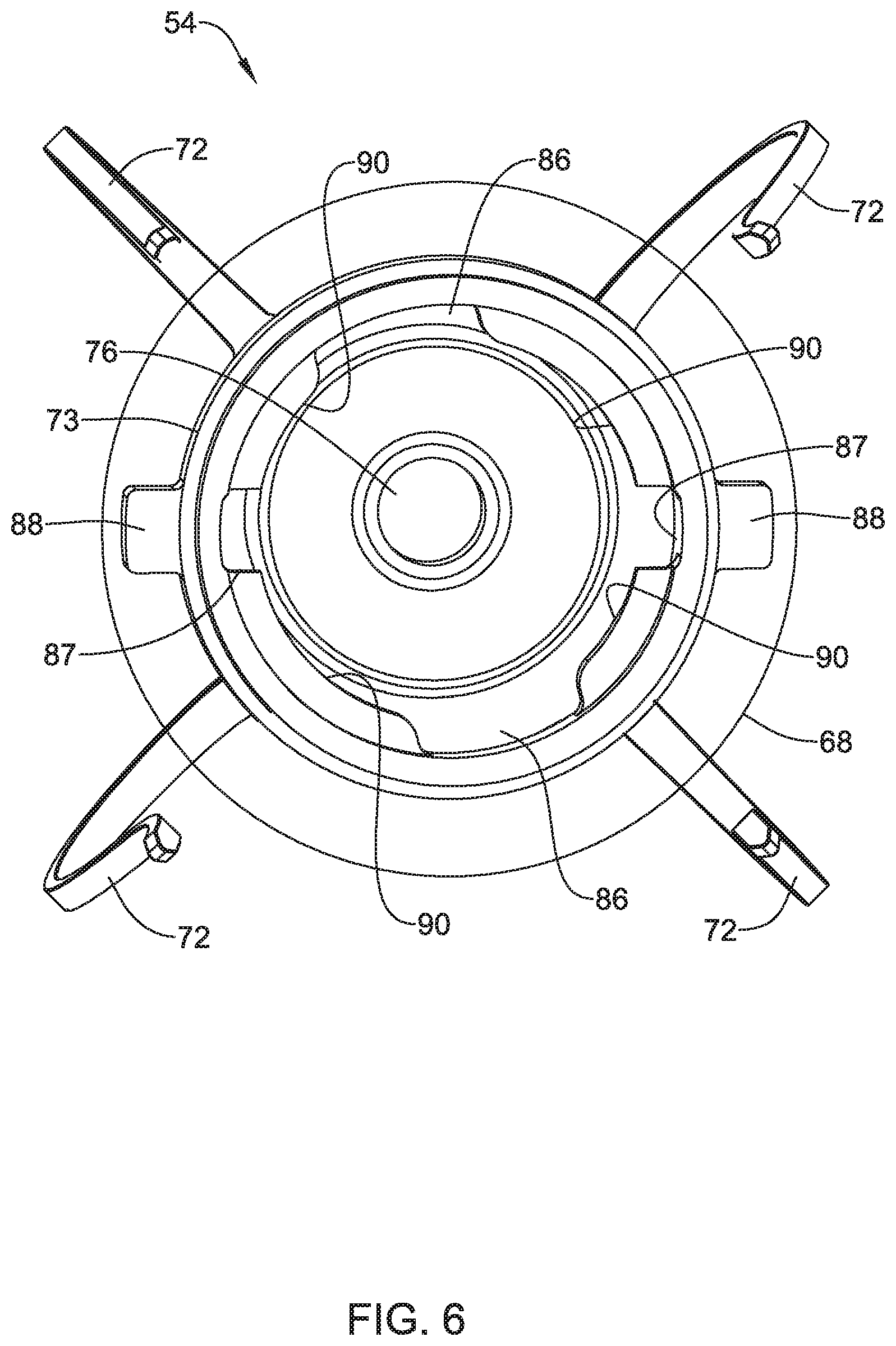
4. The IMD of claim 1, wherein the releasable connector comprises: one or more locking tabs; one more locking slots; wherein the one or more locking tabs are configured to be moved into the one or more locking slots against a bias mechanism, after which the one or more locking tabs are configured to be rotated relative to the one or more locking slots until one or more of the locking tabs are pushed into one or more retaining recesses by the bias mechanism, at which time the releasable connector is in the fully connected state.
5. The IMD of claim 4, wherein at least one of the locking tabs and a location of at least one of the retaining recesses are marked by a corresponding one or more of the first fluoroscopic markers and/or one or more of the second fluoroscopic markers.
6. The IMD of claim 4, wherein the bias mechanism comprises a silicon spring seal situated between the device module and the fixation module.
7. The IMD of claim 1, wherein the releasable connector comprises: one or more receivers; one or more catches that are biased to extend into and catch one or more of the receivers to form an interference connection when the releasable connector is in the fully connected state.
8. The IMD of claim 7, wherein the first part of a releasable connector includes the one or more receivers and the second part of a releasable connector includes the one or more catches.
9. The IMD of claim 7, wherein the releasable connector further comprises a seal for sealing the one or more receivers and the one or more catches from an external environment when the releasable connector is in the fully connected state.
10. The IMD of claim 7, wherein the releasable connector further comprises one or more electrical contacts for making an electrical connection between the first part of a releasable connector and the second part of a releasable connector.
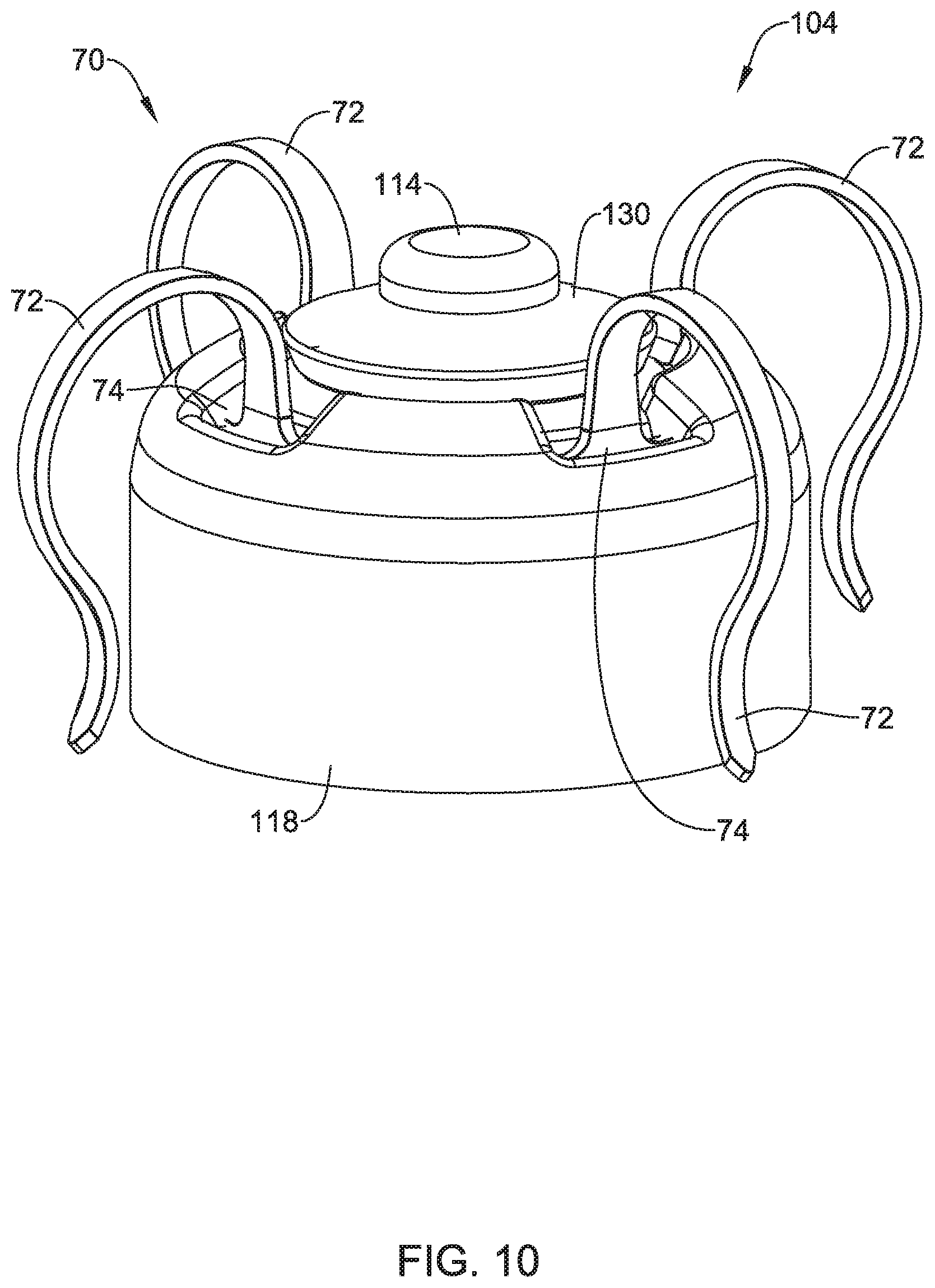
11. An implantable leadless cardiac pacemaker (LCP) configured to pace a patient's heart from a position within a cardiac chamber, the LCP comprising: a fixation module configured for engagement with the cardiac chamber and a device module that is releasably securable to the fixation module for deployment within the cardiac chamber; the fixation module comprising: a fixation module housing; a plurality of locking slots; one or more retaining recesses; an aperture configured to accommodate an electrode carried by the device module; one or more fixation module fluoroscopic markers each marking a corresponding one of the plurality of locking slots or one or more retaining recesses of the fixation module; the device module comprising: a device module housing; a plurality of locking tabs that are configured to cooperate with the locking slots of the fixation module to releasably secure the device module to the fixation module by inserting the plurality of locking tabs into the locking slots against a bias mechanism, and then rotating the device module relative to the fixation module until one or more of the locking tabs are pushed into one or more of the retaining recesses of the fixation module by the bias mechanism; one or more device module fluoroscopic markers each marking a corresponding one of the plurality of locking tabs of the device module; wherein the one or more device module fluoroscopic markers are arranged relative to the one or more fixation module fluoroscopic markers so that a predefined alignment between one or more of the fixation module fluoroscopic markers and one or more of the device module fluoroscopic markers at least partially confirms that the device module is fully secured to the fixation module; a power source disposed within the device module housing; a first electrode disposed on the device module housing and a second electrode disposed on an elongated post extending distally of the plurality of locking tabs, the elongated post configured to extend through the aperture in the fixation module housing to place the second electrode in a position where the second electrode can contact cardiac tissue when the device module is engaged with the fixation module and the LCP is implanted; and a controller disposed within the device module housing and operably coupled to the power source, the controller configured to sense cardiac electrical activity and to deliver pacing pulses via one or more of the first electrode and the second electrode.
12. The LCP of claim 11, wherein the fixation module further comprises a plurality of fixation tines that are configured to extend distally into the patient's cardiac tissue and then back proximally to hook the patient's cardiac tissue to thereby anchor the fixation module to the patient's heart.
13. The LCP of claim 11, wherein the bias mechanism comprises a resilient seal that is configured to engage corresponding mating surface on the fixation module housing and the device module housing.
14. The LCP of claim 11, wherein one or more of the locking tabs of the device module include one or more of the device module fluoroscopic markers, and wherein the fixation module comprises one or more of the fixation module fluoroscopic markers secured relative to the fixation module housing, the one or more fixation module fluoroscopic markers are configured to indicate a relative rotational orientation of the fixation module relative to the locking tabs of the device module under fluoroscopy.
15. An implantable leadless cardiac pacemaker (LCP) configured to pace a patient's heart from a position within a cardiac chamber, the LCP comprising: a fixation module configured for engagement with the cardiac chamber and a device module that is releasably securable to the fixation module for deployment within the cardiac chamber; the device module comprising: a device module housing; an elongated post extending distally from the device module housing, the elongated post comprising one or more receivers and one or more electrical contacts disposed on a side of the elongated post; the fixation module comprising: a fixation module housing; one or more electrodes on a distal side of the fixation module housing; a post receiving aperture for receiving the elongated post of the device module; one or more catches that are biased to extend into and catch one or more of the receivers of the elongated post when the elongated post is received by the post receiving aperture; and one or more electrical contacts for making an electrical connection with one or more of the electrical contacts on the side of the elongated post when the elongated post is received by the post receiving aperture, wherein one or more of the electrical contacts of the fixation module are operatively coupled to one or more of the electrodes on the distal side of the fixation module housing; and one or more fluoroscopic markers for indicating if the elongated post is sufficiently received by the post receiving aperture to be in a fully connected state.
16. The LCP of claim 15, further comprising a seal for providing a seal between the elongated post of the device module and the fixation module for sealing the one or more electrical contacts of the fixation module from an external environment when the elongated post is received by the post receiving aperture.
17. The LCP of claim 15, wherein the one or more receivers comprise one or more grooves formed in an outer surface of the elongated post.
18. The LCP of claim 17, wherein the one or more catches comprise a coil spring that is biased to extend into and catch one or more of the grooves of the elongated post.
19. The LCP of claim 17, wherein the one or more catches comprise a leaf spring that is biased to extend into and catch one or more of the grooves of the elongated post.
Description
TECHNICAL FIELD
The disclosure is directed to implantable devices such as leadless implantable devices and more particularly to leadless implantable devices with detachable fixation.
BACKGROUND
Implantable medical devices are commonly used today to monitor physiological or other parameters of a patient and/or deliver therapy to a patient. For example, to help patients with heart related conditions, various medical devices (e.g., pacemakers, defibrillators, etc.) can be implanted in a patient's body. Such devices may monitor and in some cases provide electrical stimulation (e.g. pacing, defibrillation, etc.) to the heart to help the heart operate in a more normal, efficient and/or safe manner. In another example, neuro stimulators can be used to stimulate tissue of a patient to help alleviate pain and/or other condition. In yet another example, an implantable medical device may simply be an implantable monitor that monitors one or more physiological or other parameters of the patient, and communicates the sensed parameters to another device such as another implanted medical device or an external device. In some cases, there may be a desire to remove or explant an implanted medical device and to install a replacement implanted medical device.
SUMMARY
The disclosure describes implantable medical devices (IMD), such as but not limited to leadless cardiac pacemakers (LCP), neuro-stimulators (NS), and/or implantable monitors (IM), that are configured to be implanted within the body, sometimes in or near the heart. In some cases, there may be a desire to remove or explant a first IMD and to implant a replacement second IMD. This may be desirable for any number of reasons, such as if a power source of the first IMD has reached its end of life. In some cases, the first IMD may include a fixation portion and a device portion. In some cases, the device portion may make up a majority of the first IMD, and may include a power source such as a battery or the like. After an extended period following implantation, the fixation portion of the first IMD may become entangled or otherwise captured by significant tissue overgrowth, which may make it difficult or undesirable to remove the fixation portion of the IMD. When this happens, the device portion of the first IMD may be disconnected from the fixation portion and removed from the body. The fixation portion may be left in place. In some instances, a second IMD may be implanted at a different location near the remaining fixation portion of the first IMD. In other cases, a device portion of the second IMD may be coupled to the previously installed fixation portion of the first IMD.
In one specific example, an implantable medical device (IMD) may include a fixation module, and a device module that is configured to be releasably connected to the fixation module. The device module may have a proximal end and a distal end, and may include a power source and a controller that is operably coupled to the power source. The controller may be configured to sense cardiac electrical activity via two or more electrodes and deliver pacing pulses via two or more electrodes. The device module may include a first part of a releasable connector. The fixation module may include a plurality of fixation elements for anchoring the fixation module to the patient's heart and a second part of the releasable connector, wherein the first part of the releasable connector and the second part of the releasable connector cooperate to releasably connect the device module with the fixation module. In some instances, the device module may have one or more first fluoroscopic markers and the fixation module having one or more second fluoroscopic markers, wherein the one or more first fluoroscopic markers and the one or more second fluoroscopic markers are arranged so that a predefined alignment between one or more of the first fluoroscopic markers and one or more of the second fluoroscopic markers confirms that the releasable connector is in a fully connected state.
Alternatively or additionally, the device module may further include a proximal electrode and a distal electrode each operatively coupled to the controller, wherein the distal electrode is disposed on an elongated post extending distally from the first part of the releasable connector, and wherein the fixation module defines an aperture through which the elongated post extends to support the distal electrode on a distal side of the fixation module when the releasable connector is in the fully connected state.
Alternatively or additionally, the device module may further include a proximal electrode and a distal terminal each operatively coupled to the controller, and wherein the fixation module includes a distal electrode on a distal side of the fixation module, and wherein the distal terminal of the device module is operatively coupled to the distal electrode of the fixation module when the releasable connector is in the fully connected state.
Alternatively or additionally, the releasable connector may include one or more locking tabs and one more locking slots. The one or more locking tabs may be configured to be moved into the one or more locking slots against a bias mechanism, after which the one or more locking tabs are configured to be rotated relative to the one or more locking slots until one or more of the locking tabs are pushed into one or more retaining recesses by the bias mechanism, at which time the releasable connector is in the fully connected state.
Alternatively or additionally, at least one of the locking tabs and a location of at least one of the retaining recesses are marked by a corresponding fluoroscopic marker.
Alternatively or additionally, the bias mechanism may include a silicone spring seal situated between the device module and the fixation module.
Alternatively or additionally, the releasable connector may include one or more receivers and one or more catches that are biased to extend into and catch one or more of the receivers to form an interference connection when the releasable connector is in the fully connected state.
Alternatively or additionally, the first part of a releasable connector may include the one or more receivers and the second part of a releasable connector may include the one or more catches.
Alternatively or additionally, the releasable connector may further include a seal for sealing the one or more receivers and the one or more catches from an external environment when the releasable connector is in the fully connected state.
Alternatively or additionally, the releasable connector may further include one or more electrical contacts for making an electrical connection between the first part of a releasable connector and the second part of a releasable connector.
In another example, an implantable leadless cardiac pacemaker (LCP) that is configured to pace a patient's heart from a position within a cardiac chamber may include a fixation module that is configured for engagement with the cardiac chamber and a device module that is releasably securable to the fixation module for deployment within the cardiac chamber. The fixation module may include a fixation module housing, a plurality of locking slots, one or more retaining recesses and an aperture that is configured to accommodate an electrode carried by the device module. The device module may include a device module housing and a plurality of locking tabs that are configured to cooperate with the locking slots of the fixation module to releasably secure the device module to the fixation module by inserting the plurality of locking tabs into the locking slots against a bias mechanism, and then rotating the device module relative to the fixation module until one or more of the locking tabs are pushed into one or more of the retaining recesses of the fixation module by the bias mechanism. A power source is disposed within the device module housing. A first electrode may be disposed on the device module housing and a second electrode may be disposed on an elongated post extending distally of the plurality of locking tabs, the elongated post configured to extend through the aperture in the fixation module housing to place the second electrode in a position where the second electrode can contact cardiac tissue when the device module is engaged with the fixation module and the LCP is implanted. A controller may be disposed within the device module housing and may be operably coupled to the power source, the controller configured to sense cardiac electrical activity and to deliver pacing pulses via one or more of the first electrode and the second electrode.
Alternatively or additionally, the fixation module may further include a plurality of fixation tines that are configured to extend distally into the patient's cardiac tissue and then back proximally to hook the patient's cardiac tissue to thereby anchor the fixation module to the patient's heart.
Alternatively or additionally, the bias mechanism may be a resilient seal that is configured to engage corresponding mating surface on the fixation module housing and the device module housing.
Alternatively or additionally, one or more of the locking tabs of the device module may include a fluoroscopic marker, and the fixation module may include one or more fluoroscopic markers secured relative to the fixation module housing, the one or more fluoroscopic markers of the fixation module may be configured to indicate an orientation of the fixation module relative to the locking tabs of the device module under fluoroscopy.
In another example, an implantable leadless cardiac pacemaker (LCP) that is configured to pace a patient's heart from a position within a cardiac chamber includes a fixation module that is configured for engagement with the cardiac chamber and a device module that is releasably securable to the fixation module for deployment within the cardiac chamber. The device module includes a device module housing and an elongated post that extends distally from the device module housing and that includes one or more receivers and one or more electrical contacts. The fixation module includes a fixation module housing and one or more electrodes on a distal side of the fixation module housing. The fixation module includes a post receiving aperture for receiving the elongated post of the device module as well as one or more catches that are biased to extend into and catch one or more of the receivers of the elongated post when the elongated post is received by the post receiving aperture. The fixation module includes one or more electrical contacts for making an electrical connection with one or more of the electrical contacts of the elongated post when the elongated post is received by the post receiving aperture, wherein one or more of the electrical contacts of the fixation module are operatively coupled to one or more of the electrodes on the distal side of the fixation module housing.
Alternatively or additionally, the LCP may further include a seal for providing a seal between the elongated post of the device module and the fixation module for sealing the one or more electrical contacts of the fixation module from an external environment when the elongated post is received by the post receiving aperture.
Alternatively or additionally, the one or more receivers may include one or more grooves formed in an outer surface of the elongated post.
Alternatively or additionally, the one or more catches may include a coil spring that is biased to extend into and catch one or more of the grooves of the elongated post.
Alternatively or additionally, the one or more catches may include a leaf spring that is biased to extend into and catch one or more of the grooves of the elongated post.
Alternatively or additionally, the LCP may further include one or more fluoroscopic markers for indicating if the elongated post is sufficiently received by the post receiving aperture to be in a fully connected state.
The above summary of some embodiments is not intended to describe each disclosed embodiment or every implementation of the present disclosure. The Figures and Detailed Description, which follow, more particularly exemplify these embodiments.
BRIEF DESCRIPTION OF THE FIGURES
The disclosure may be more completely understood in consideration of the following description of in connection with the accompanying drawings, in which:
FIG. 1 is a schematic block diagram of an illustrative implantable medical device (IMD) in accordance with the disclosure;
FIG. 2 is a side view of an implantable leadless cardiac pacemaker (LCP) as an example of the IMD of FIG. 1;
FIG. 3 is a side view of a device module forming a portion of the LCP of FIG. 2;
FIG. 4 is a perspective view of a fixation module forming a portion of the LCP of FIG. 2;
FIG. 5 is a perspective end view of the device module of FIG. 3;
FIG. 6 is a bottom perspective view of the fixation module of FIG. 4;
FIG. 7 is an end view of the LCP of FIG. 2, with portions shown as transparent to reveal internal details;
FIG. 8 is a side view of an LCP as another example of the IMD of FIG. 1;
FIG. 9 is a side view of a device module forming a portion of the LCP of FIG. 8;
FIG. 10 is a perspective view of a fixation module forming a portion of the LCP of FIG. 8;
FIG. 11 is a bottom perspective view of the fixation module of FIG. 10;
FIG. 12 is a perspective end view of the device module of FIG. 9;
FIG. 13 is an example schematic cross-sectional view taken through the distal end of the LCP of FIG. 8;
FIG. 14 is another example schematic cross-sectional view taken through the distal end of the LCP of FIG. 8;
FIG. 15 is an end view of the LCP of FIG. 8, with portions shown as transparent to reveal internal details; and
FIG. 16 is a schematic block diagram of an illustrative LCP in accordance with an example of the disclosure.
While the disclosure is amenable to various modifications and alternative forms, specifics thereof have been shown by way of example in the drawings and will be described in detail. It should be understood, however, that the intention is not to limit the invention to the particular embodiments described. On the contrary, the intention is to cover all modifications, equivalents, and alternatives falling within the spirit and scope of the disclosure.
DESCRIPTION
For the following defined terms, these definitions shall be applied, unless a different definition is given in the claims or elsewhere in this specification.
All numeric values are herein assumed to be modified by the term "about", whether or not explicitly indicated. The term "about" generally refers to a range of numbers that one of skill in the art would consider equivalent to the recited value (i.e., having the same function or result). In many instances, the term "about" may be indicative as including numbers that are rounded to the nearest significant figure.
The recitation of numerical ranges by endpoints includes all numbers within that range (e.g., 1 to 5 includes 1, 1.5, 2, 2.75, 3, 3.80, 4, and 5).
Although some suitable dimensions, ranges and/or values pertaining to various components, features and/or specifications are disclosed, one of skill in the art, incited by the present disclosure, would understand desired dimensions, ranges and/or values may deviate from those expressly disclosed.
As used in this specification and the appended claims, the singular forms "a," "an," and "the" include or otherwise refer to singular as well as plural referents, unless the content clearly dictates otherwise. As used in this specification and the appended claims, the term "or" is generally employed to include "and/or," unless the content clearly dictates otherwise.
The following detailed description should be read with reference to the drawings in which similar elements in different drawings are numbered the same. The detailed description and the drawings, which are not necessarily to scale, depict illustrative embodiments and are not intended to limit the scope of the disclosure. The illustrative embodiments depicted are intended only as exemplary. Selected features of any illustrative embodiment may be incorporated into an additional embodiment unless clearly stated to the contrary.
The disclosure is directed to implantable medical devices (IMD) that may include a device module and a fixation module. In some cases, the IMD may be implanted with the device module secured to the fixation module and thus may be provided as a single structure and may be implanted using any desired implantation technique and/or delivery device. In some cases, after the IMD has been implanted, there may be a desire to remove the IMD and/or to replace the IMD. For example, an IMD may be removed and replaced when the power source (e.g. battery) in the implanted IMD has reached the end of its expected life. In some cases, the fixation portion of an IMD may be located at a good site for pacing and/or sensing, and there may be interest in being able to place the replacement IMD at the same location. In some instances, due to tissue ingrowth and the like, the fixation portion of the IMD may be difficult to remove. Accordingly, in some cases, the device module may be removed from the fixation module and removed from the patient. In some instances, a new device module may be delivered and secured to the previously implanted fixation module. In some cases, the previously implanted fixation module may simply be left in place, and a new IMD having a new device module and a new fixation module may be delivered and implanted at a new implantation site. These are just examples.
Turning to FIG. 1, an implantable medical device (IMD) 10 is shown. The illustrative IMD 10 includes a device module 12 and a fixation module 14. It will be appreciated that FIG. 1 is highly schematic. The device module 12 has a device housing 16 that extends from a proximal end 18 to a distal end 20. The illustrative device module 12 includes a power supply 22 and a controller 24 that is operably coupled to the power supply 22. In some cases, the controller 24 may be configured to sense cardiac electrical activity via two or more electrodes and to deliver pacing pulses via two or more electrodes that may be the same as those used to sense cardiac electrical activity or that may be different than those used to sense cardiac electrical activity. The device module 12 is illustrated as having a first electrode 26 and a second electrode 28. It will be appreciated that the first electrode 26 and the second electrode 28 may be disposed at any desired location or position relative to the device housing 16, and in some cases, may be located on the proximal end 18 and/or distal end 20. In some cases, there may be additional electrodes as well.
In some instances, as will be discussed with respect to subsequent Figures, at least one of the first electrode 26 and the second electrode 28 may be disposed at or even extend distally beyond the distal end 20 of the device housing 16. In some cases, at least one of the first electrode 26 and the second electrode 28 may extend distally from the device module 12 a distance sufficient to permit the electrode to extend through the fixation module 14 and contact tissue. In some instances, at least one of the first electrode 26 and the second electrode 28 may actually be secured to the fixation module 14. FIGS. 2 through 7 provide examples of an IMD in which an electrode extends distally from the device module 12 and through the fixation module 14 to contact tissue. FIGS. 8 through 15 provide examples of an IMD in which an electrode is secured to the fixation module 14, and the fixation module 14 operatively connects the distal electrode of the device module to an electrode of the fixation module 14.
In FIG. 1, the device module 12 also includes a first connector part 30 and the fixation module 14 includes a second connector part 32. In some cases, the first connector part 30 and the second connector part 32 may, in combination, be considered as forming a releasable connector 34. In some cases, the first connector part 30 and the second connector part 32 cooperate to releasably connect the device module 12 with the fixation module 14. The fixation module 14 may be considered as having a fixation housing 36 extending from a proximal end 38 to a distal end 40. The second connector part 32 may be secured to the proximal end 38 of the fixation housing 36. A fixation structure 42 may be secured to the distal end 40 of the fixation housing 36. In some cases, the fixation structure 42 may schematically represent an active fixation structure such as a fixation helix. In some instances, the fixation structure 42 may schematically represent a passive fixation structure such as fixation tines. Subsequent Figures will provide examples of fixation tines.
In some cases, as will be shown in subsequent Figures, the device module 12 may include one or more first fluoroscopic markers and the fixation module 14 may include one or more second fluoroscopic markers. The one or more first fluoroscopic markers and the one or more second fluoroscopic markers may be arranged so that a predefined alignment between one or more of the first fluoroscopic markers and one or more of the second fluoroscopic markers confirms that the releasable connector 34 is in a fully connected state and/or a fully disconnected state.
FIGS. 2 through 7 illustrate an IMD 50 that may be considered as being a leadless cardiac pacemaker (LCP). The illustrative IMD 50 includes a device module 52, shown separately in FIG. 3, and a fixation module 54, shown separately in FIG. 4. The device module 52 includes a device housing 56 extending from a proximal end 58 to a distal end 60. The illustrative device module 52 includes a retrieval feature 62 secured relative to the proximal end 58. At the distal end 60, the device module 52 is coupled to the fixation module 54. In some cases, as best seen in FIG. 3, the device module 52 may include a distal electrode 64 extending distally on a distal post 66. The distal electrode 64 may be operably coupled to the controller 24 (FIG. 1). The device module 52 may also include a proximal electrode 65 that is operably coupled to the controller 24 (FIG. 1). As shown, the proximal electrode 65 may be a ring electrode, but this is not required in all cases. The distal post 66 provides a mechanical and electrical connection between the distal electrode 64 and the controller 24, and the distal post 66 is dimensioned to allow the distal electrode 64 to extend distally from the fixation module 54 when the fixation module is releasably connected to the device module 52.
As illustrated, the fixation module 54 includes a fixation housing 68 and a fixation tines assembly 70. In some cases, the fixation tines assembly 70 may include one or more passive fixation tines 72 (four are shown) that extend through corresponding apertures 74 formed within the fixation housing 68. In some cases the passive fixation tines 72 are coupled to or integrally formed with a ring 73 (FIG. 6) that joins the passive fixation tines 72 together underneath the fixation housing 68 and helps secure the passive fixation tines 72 to each other and in place relative to the fixation housing 68. As seen for example in FIG. 4, the fixation housing 68 may include a central aperture 76 that is sized to accommodate the distal electrode 64, and may in some cases include a recessed portion 78 that may be dimensioned to accommodate a drug collar 80 (shown in FIG. 2).
FIGS. 5 through 7 provide additional details regarding how the device module 52 may be releasably coupled to the fixation module 54. In some cases, the device module 52 includes one or more locking tabs 82. While a pair of locking tabs 82 are illustrated, in some cases there may be three or more locking tabs 82. In some cases, each of the one or more locking tabs 82 may include a fluoroscopic marker 84. As can be seen in FIG. 6, the fixation module 54 may include one or more corresponding locking slots 86. While a pair of locking slots 86 are shown, in some cases there may be three or more locking slots 86 in order to accommodate however many locking tabs 82 are present on the device module 52. In some instances, a fluoroscopic marker 88 may be disposed radially outwardly from each of the one or more locking slots 86 in order to help visualize the location of the one or more locking slots 86 under fluoroscopy.
In the example shown, the one or more locking slots 86 are separated by retention structures 90. In some cases, the device module 52 may be secured to the fixation module 54 by aligning the one or more locking tabs 82 with the corresponding one or more locking slots 86. As will be appreciated, this may be done by visually aligning (under fluoroscopy) the fluoroscopic markers 84 (on the one or more locking tabs 82) with the fluoroscopic markers 88 (adjacent to the one or more locking slots 86). Once the one or more locking tabs 82 are aligned with the corresponding one or more locking slots 86, the device module 52 may be secured in place by moving the device module 52 distally relative to the fixation module 54 such that the one or more locking tabs 82 penetrate into the one or more locking slots 86. The device module 52 may then be rotated relative to the fixation module 54 to move the one or more locking tabs 82 into position beneath the retention structures 90. In some cases, the device module 52 may be rotated 90 degrees. In some cases, the one or more locking tabs 82 are held in position at one or more corresponding retention recesses 87.
In some cases, pushing the device module 52 distally relative to the fixation module 54 involves pushing against a bias mechanism that will, as can be appreciated, help to hold the one or more locking tabs 82 in position against the retention structures 90, and thus help to prevent accidental separation of the device module 52 from the fixation module 54, particularly after implantation. In some cases, the bias mechanism may be a silicone spring seal 92 that is secured to the device module 52. In some cases, the retention structures 90 may themselves include retaining recesses that the one or more locking tabs 82 may fit into and be held in place by the bias mechanism.
In some cases, each of the one or more locking tabs 82 may be considered as being catches, and a back side of the retention structures 90 may include one or more receivers, where each of the catches are biased to extend into the receivers to form an interference connection when the device module 52 is fully connected to the fixation module 54. FIG. 7 shows the completed assembly, with the fixation housing 68 shown as being transparent so that the relative arrangement of the one or more locking tabs 82 and the corresponding one or more locking slots 86 may be seen.
FIGS. 8 through 15 illustrate an IMD 100 that may be considered as being a leadless cardiac pacemaker (LCP). The illustrative IMD 100 includes a device module 102, shown separately in FIG. 9, and a fixation module 104, shown separately in FIG. 10. The device module 102 includes a device housing 106 extending from a proximal end 108 to a distal end 110. The illustrative device module 102 includes a retrieval feature 112 secured relative to the proximal end 108. At the distal end 110, the device module 102 is coupled to the fixation module 104. In some cases, as shown, the device module 102 includes a proximal electrode 115 that is operably coupled to the controller 24 (FIG. 1). As shown, the proximal electrode 115 is a ring electrode, but this is not required in all cases. In some cases, the fixation module 104 includes a distal electrode 114 that is operably coupled to the controller 24.
As illustrated, the fixation module 104 includes a fixation housing 118 and a fixation tines assembly 70. In some cases, the fixation tines assembly 70 may include one or more passive fixation tines 72 (four are shown) that extend through corresponding apertures 74 formed within the fixation housing 118. In some cases, although not expressly shown here, the passive fixation tines 72 are coupled to or integrally formed with a ring that joins the passive fixation tines 72 together underneath the fixation housing 118 and that helps to secure the passive fixation tines 72 to each other and in place relative to the fixation housing 118. See, for example, the ring 73 referenced previously with respect to FIG. 6. In some cases, a drug collar 130 (see FIG. 8) may be disposed relative to the fixation housing 118.
Because the distal electrode 114 is secured relative to the fixation module 104, rather than directly to the device module 102, there is a need to provide an electrical connection between the controller 24 (FIG. 1), in the device module 102, and the distal electrode 114. As can be seen for example in FIGS. 9 and 12, the illustrative device module 102 includes a distal terminal 140 that is operably coupled to the controller 24 and extends distally from the distal end 110 of the device housing 106. In some cases, as shown, the distal terminal 140 may have a tapered distal end 142 to facilitate insertion into the fixation module 104. A detent 144 may be used, as will be discussed, to also provide a releasable mechanical connection between the device module 102 and the fixation module 104. In some cases, the distal terminal 140 may include one or more seals 146 in order to help prevent fluids from bridging conductors and/or causing a short to body fluids (e.g. blood). At least the distal end 142 may be considered as being electrically active. In some cases, if desired, a secondary seal 148 may be located at or near the distal end 110.
As can be seen for example in FIGS. 11, 13 and 14, the fixation module 104 may include a connection assembly 150. In some cases, for example, the distal terminal 140 (part of the device module 102) may be considered as a first connector part and the connection assembly 150 (part of the fixation module 104) may be considered as a second connector part. The first connector part and the second connector part may, for example, be considered as forming a releasable connector that provides an electrical connection between the controller 24 (FIG. 1) and the distal electrode 114 as well as providing a mechanical connection between the device module 102 and the fixation module 104.
The illustrative connection assembly 150 includes an aperture 152 (best seen in FIG. 11) that is configured to accommodate the distal terminal 140. As shown in FIG. 13, in some cases the connection assembly 150 includes leaf spring contacts 154 that help to provide an electrical connection between the distal terminal 140 and the distal electrode 114. The leaf spring contacts 154 may be positioned such that they extend into the detent 144. The leaf spring contacts 154 may be configured to flex as the distal terminal 140 is inserted through the aperture 152 and into the connection assembly 150 and then may snap into the detent 144. The leaf spring contacts 154, once snapped into the detent 144, may be considered as a suitable releasable mechanical connection between the device module 102 and the fixation module 104 that secures the device module 102 to the fixation module 104 against accidental separation but permits separation when desired.
FIG. 14 shows an example in which the connection assembly 150 includes a toroidal coil spring contact 164. The coil spring contact 164 may be configured to flex as the distal terminal 140 is inserted through the aperture 152 and into the connection assembly 150 and may snap into the detent 144. It will be appreciated that this may provide a mechanical connection between the device module 102 and the fixation module 104. The coil spring contact 164, once snapped into the detent 144, may be considered as a suitable releasable mechanical connection between the device module 102 and the fixation module 104 that secures the device module 102 to the fixation module 104 against accidental separation but permits separation when desired. In some cases, the coil spring contacts 164 may be configured to have a relatively lower insertion force and a relatively higher withdrawal force in order to facilitate assembly but discourage accidental disassembly. This may be accomplished by having a toroidal coil spring that is formed by a wound wire, wherein the wound wire is bent to have a smaller radius R.sub.1 along the top of the donut shaped coil spring than the radius R.sub.2 along the bottom of the donut shaped coil spring. This is just one example.
FIG. 15 is a perspective view of a portion of the IMD 100, with the fixation housing 118 shown as being transparent in order to see internal details. In particular, there may be a first fluoroscopic ring 170 secured to the distal terminal 140 and a second fluoroscopic ring 172 secured to the fixation housing 118. As the device module 102 is being inserted into the fixation module 104, the first fluoroscopic ring 170 will be mis-aligned with the second fluoroscopic ring 172, but will become closer to the second fluoroscopic ring 172 as the device module 102 is inserted toward the fully connected state (e.g. the leaf spring contacts 154 snap into the detent 144 or the coil spring contact 164 snaps into the detent 144). When the first fluoroscopic ring 170 is axially aligned with the second fluoroscopic ring 172, this is an indication that the device module 102 is fully inserted into the fixation module 104. In some cases, depending on the relative angle at which this is being viewed, the first fluoroscopic ring 170 and the second fluoroscopic ring 172 may appear either brighter or darker, depending on whether a positive image or a negative image was being displayed by the fluoroscope.
FIG. 16 is a schematic block diagram of an illustrative LCP in accordance with an example of the disclosure. The illustrative LCP may be implanted into a patient and may operate to deliver appropriate therapy to the heart, such as to deliver anti-tachycardia pacing (ATP) therapy, cardiac resynchronization therapy (CRT), bradycardia therapy, and/or the like. As can be seen in FIG. 16, the illustrative LCP 200 may be a compact device with all components housed within or directly on a housing 220. In some cases, the LCP 200 may be considered as being an example of the IMD 10 (FIG. 1), the IMD 50 (FIG. 2) or the IMD 100 (FIG. 8). In some instances, the LCP 200 may include one or more of a communication module 202, a pulse generator module 204, an electrical sensing module 206, a mechanical sensing module 208, a processing module 210, an energy storage module 212 (e.g., a battery), and electrodes 214.
As depicted in FIG. 16, the LCP 200 may include electrodes 214, which can be secured relative to the housing 220 and electrically exposed to tissue and/or blood surrounding the LCP 200. The electrodes 214 may generally conduct electrical signals to and from the LCP 200 and the surrounding tissue and/or blood. Such electrical signals can include communication signals, electrical stimulation pulses, and intrinsic cardiac electrical signals, to name a few. Intrinsic cardiac electrical signals may include electrical signals generated by the heart and may be represented by an electrocardiogram (ECG).
The electrodes 214 may include one or more biocompatible conductive materials such as various metals or alloys that are known to be safe for implantation within a human body. In some instances, the electrodes 214 may be generally disposed on either end of the LCP 200 and may be in electrical communication with one or more of the modules 202, 204, 206, 208, and 210. In embodiments where the electrodes 214 are secured directly to the housing 220, an insulative material may electrically isolate the electrodes 214 from adjacent electrodes, the housing 220, and/or other parts of the LCP 200. In some instances, some or all of the electrodes 214 may be spaced from the housing 220 and may be connected to the housing 220 and/or other components of the LCP 200 through connecting wires. In such instances, the electrodes 214 may be placed on a tail (not shown) that extends out away from the housing 220. As shown in FIG. 16, in some embodiments, the LCP 200 may include electrodes 214'. The electrodes 214' may be in addition to the electrodes 214, or may replace one or more of the electrodes 214. The electrodes 214' may be similar to the electrodes 214 except that the electrodes 214' are disposed on the sides of the LCP 200. In some cases, the electrodes 214' may increase the number of electrodes by which the LCP 200 may deliver communication signals and/or electrical stimulation pulses, and/or may sense intrinsic cardiac electrical signals, communication signals, and/or electrical stimulation pulses.
The electrodes 214 and/or 214' may assume any of a variety of sizes and/or shapes, and may be spaced at any of a variety of spacings. For example, the electrodes 214 may have an outer diameter of two to twenty millimeters (mm). In other embodiments, the electrodes 214 and/or 214' may have a diameter of two, three, five, seven millimeters (mm), or any other suitable diameter, dimension and/or shape. Example lengths for the electrodes 214 and/or 214' may include, for example, one, three, five, ten millimeters (mm), or any other suitable length. As used herein, the length is a dimension of the electrodes 214 and/or 214' that extends away from the outer surface of the housing 220. In some instances, at least some of the electrodes 214 and/or 214' may be spaced from one another by a distance of twenty, thirty, forty, fifty millimeters (mm), or any other suitable spacing. The electrodes 214 and/or 214' of a single device may have different sizes with respect to each other, and the spacing and/or lengths of the electrodes on the device may or may not be uniform.
In the embodiment shown, the communication module 202 may be electrically coupled to two or more of the electrodes 214, 214' and may be configured to deliver communication pulses to tissues of the patient for communicating with other devices such as sensors, programmers, other medical devices, and/or the like. Communication signals, as used herein, may be any modulated signal that conveys information to another device, either by itself or in conjunction with one or more other modulated signals. In some embodiments, communication signals may be limited to sub-threshold signals that do not result in capture of the heart yet still convey information. The communication signals may be delivered to another device that is located either external or internal to the patient's body. In some instances, the communication may take the form of distinct communication pulses separated by various amounts of time. In some of these cases, the timing between successive pulses may convey information. The communication module 202 may additionally be configured to sense for communication signals delivered by other devices, which may be located external or internal to the patient's body.
The communication module 202 may communicate to help accomplish one or more desired functions. Some example functions include delivering sensed data, using communicated data for determining occurrences of events such as arrhythmias, coordinating delivery of electrical stimulation therapy, and/or other functions. In some cases, the LCP 200 may use communication signals to communicate raw information, processed information, messages and/or commands, and/or other data. Raw information may include information such as sensed electrical signals (e.g. a sensed ECG), signals gathered from coupled sensors, and the like. In some embodiments, the processed information may include signals that have been filtered using one or more signal processing techniques. Processed information may also include parameters and/or events that are determined by the LCP 200 and/or another device, such as a determined heart rate, timing of determined heartbeats, timing of other determined events, determinations of threshold crossings, expirations of monitored time periods, accelerometer signals, activity level parameters, blood-oxygen parameters, blood pressure parameters, heart sound parameters, and the like. In some cases, processed information may, for example, be provided by a chemical sensor or an optically interfaced sensor. Messages and/or commands may include instructions or the like directing another device to take action, notifications of imminent actions of the sending device, requests for reading from the receiving device, requests for writing data to the receiving device, information messages, and/or other messages commands.
In at least some embodiments, the communication module 202 (or the LCP 200) may further include switching circuitry to selectively connect one or more of the electrodes 214, 214' and/or 214'' to the communication module 202 in order to select which of the electrodes 214, 214' and/or 214'' that the communication module 202 delivers communication pulses with. It is contemplated that the communication module 202 may be communicating with other devices via conducted signals, radio frequency (RF) signals, optical signals, acoustic signals, inductive coupling, and/or any other suitable communication methodology. Where the communication module 202 generates electrical communication signals, the communication module 202 may include one or more capacitor elements and/or other charge storage devices to aid in generating and delivering communication signals. In the embodiment shown, the communication module 202 may use energy stored in the energy storage module 212 to generate the communication signals. In at least some examples, the communication module 202 may include a switching circuit that is connected to the energy storage module 212 and, with the switching circuitry, may connect the energy storage module 212 to one or more of the electrodes 214/214'/214'' to generate the communication signals.
As shown in FIG. 16, a pulse generator module 204 may be electrically connected to one or more of the electrodes 214, 214' and/or 214''. The pulse generator module 204 may be configured to generate electrical stimulation pulses and deliver the electrical stimulation pulses to tissues of a patient via one or more of the electrodes 214, 214' and/or 214'' in order to effectuate one or more electrical stimulation therapies. Electrical stimulation pulses as used herein are meant to encompass any electrical signals that may be delivered to tissue of a patient for purposes of treatment of any type of disease or abnormality. For example, when used to treat heart disease, the pulse generator module 204 may generate electrical stimulation pacing pulses for capturing the heart of the patient, i.e. causing the heart to contract in response to the delivered electrical stimulation pulse. In some of these cases, the LCP 200 may vary the rate at which the pulse generator module 204 generates the electrical stimulation pulses, for example in rate adaptive pacing. In other embodiments, the electrical stimulation pulses may include defibrillation/cardioversion pulses for shocking the heart out of fibrillation or into a normal heart rhythm. In yet other embodiments, the electrical stimulation pulses may include anti-tachycardia pacing (ATP) pulses. It should be understood that these are just some examples. The pulse generator module 204 may include one or more capacitor elements and/or other charge storage devices to aid in generating and delivering appropriate electrical stimulation pulses. In at least some embodiments, the pulse generator module 204 may use energy stored in the energy storage module 212 to generate the electrical stimulation pulses. In some particular embodiments, the pulse generator module 204 may include a switching circuit that is connected to the energy storage module 212 and may connect the energy storage module 212 to one or more of the electrodes 214/214'/214'' to generate electrical stimulation pulses. In some cases, the pulse generator module 204 may provide pacing pulses to pace the RV of the heart H using electrode 214, and may provide pacing pulses to the LV of the heart H using electrode 214''. In some cases, the pacing pulses generated for pacing the RV of the heart H by the pulse generator module 204 may be offset in time, have a different duration, have a different amplitude and/or have a different shape from the pacing pulses generated by the pulse generator module 204 for pacing the LV of the heart H, if desired.
The LCP 200 may further include an electrical sensing module 206 and a mechanical sensing module 208. The electrical sensing module 206 may be configured to sense intrinsic cardiac electrical signals conducted from the electrodes 214, 214' and/or 214'' to the electrical sensing module 206. For example, the electrical sensing module 206 may be electrically connected to one or more of the electrodes 214, 214' and/or 214'' and the electrical sensing module 206 may be configured to receive cardiac electrical signals conducted through the electrodes 214, 214' and/or 214'' via a sensor amplifier or the like. In some embodiments, the cardiac electrical signals from electrodes 214 and/or 214' may represent local information from the RV, while the cardiac electrical signals from LV electrode 214'' may represent local information from the LV of the heart H.
The mechanical sensing module 208 may include, or be electrically connected to, various sensors, such as accelerometers, including multi-axis accelerometers such as two- or three-axis accelerometers, gyroscopes, including multi-axis gyroscopes such as two- or three-axis gyroscopes, blood pressure sensors, heart sound sensors, piezoelectric sensors, blood-oxygen sensors, and/or other sensors which measure one or more physiological parameters of the heart and/or patient. Mechanical sensing module 208, when present, may gather signals from the sensors indicative of the various physiological parameters. The electrical sensing module 206 and the mechanical sensing module 208 may both be connected to the processing module 210 and may provide signals representative of the sensed cardiac electrical signals and/or physiological signals to the processing module 210. Although described with respect to FIG. 16 as separate sensing modules, in some embodiments, the electrical sensing module 206 and the mechanical sensing module 208 may be combined into a single module. In at least some examples, the LCP 200 may only include one of the electrical sensing module 206 and the mechanical sensing module 208. In some cases, any combination of the processing module 210, the electrical sensing module 206, the mechanical sensing module 208, the communication module 202, the pulse generator module 204 and/or the energy storage module may be considered a controller of the LCP 200.
The processing module 210 may be configured to direct the operation of the LCP 200 and may, in some embodiments, be termed a controller. For example, the processing module 210 may be configured to receive cardiac electrical signals from the electrical sensing module 206 and/or physiological signals from the mechanical sensing module 208. Based on the received signals, the processing module 210 may determine, for example, occurrences and types of arrhythmias and other determinations such as whether the LCP 200 has become dislodged. The processing module 210 may further receive information from the communication module 202. In some embodiments, the processing module 210 may additionally use such received information to determine occurrences and types of arrhythmias and/or and other determinations such as whether the LCP 200 has become dislodged. In still some additional embodiments, the LCP 200 may use the received information instead of the signals received from the electrical sensing module 206 and/or the mechanical sensing module 208--for instance if the received information is deemed to be more accurate than the signals received from the electrical sensing module 206 and/or the mechanical sensing module 208 or if the electrical sensing module 206 and/or the mechanical sensing module 208 have been disabled or omitted from the LCP 200.
After determining an occurrence of an arrhythmia, the processing module 210 may control the pulse generator module 204 to generate electrical stimulation pulses in accordance with one or more electrical stimulation therapies to treat the determined arrhythmia. For example, the processing module 210 may control the pulse generator module 204 to generate pacing pulses with varying parameters and in different sequences to effectuate one or more electrical stimulation therapies. As one example, in controlling the pulse generator module 204 to deliver bradycardia pacing therapy, the processing module 210 may control the pulse generator module 204 to deliver pacing pulses designed to capture the heart of the patient at a regular interval to help prevent the heart of a patient from falling below a predetermined threshold. In some cases, the rate of pacing may be increased with an increased activity level of the patient (e.g. rate adaptive pacing). For instance, the processing module 210 may monitor one or more physiological parameters of the patient which may indicate a need for an increased heart rate (e.g. due to increased metabolic demand). The processing module 210 may then increase the rate at which the pulse generator module 204 generates electrical stimulation pulses. Adjusting the rate of delivery of the electrical stimulation pulses based on the one or more physiological parameters may extend the battery life of the LCP 200 by only requiring higher rates of delivery of electrical stimulation pulses when the physiological parameters indicate there is a need for increased cardiac output. Additionally, adjusting the rate of delivery of the electrical stimulation pulses may increase a comfort level of the patient by more closely matching the rate of delivery of electrical stimulation pulses with the cardiac output need of the patient.
For ATP therapy, the processing module 210 may control the pulse generator module 204 to deliver pacing pulses at a rate faster than an intrinsic heart rate of a patient in attempt to force the heart to beat in response to the delivered pacing pulses rather than in response to intrinsic cardiac electrical signals. Once the heart is following the pacing pulses, the processing module 210 may control the pulse generator module 204 to reduce the rate of delivered pacing pulses down to a safer level. In CRT, the processing module 210 may control the pulse generator module 204 to deliver pacing pulses in coordination with another device to cause the heart to contract more efficiently. In cases where the pulse generator module 204 is capable of generating defibrillation and/or cardioversion pulses for defibrillation/cardioversion therapy, the processing module 210 may control the pulse generator module 204 to generate such defibrillation and/or cardioversion pulses. In some cases, the processing module 210 may control the pulse generator module 204 to generate electrical stimulation pulses to provide electrical stimulation therapies different than those examples described above.
Aside from controlling the pulse generator module 204 to generate different types of electrical stimulation pulses and in different sequences, in some embodiments, the processing module 210 may also control the pulse generator module 204 to generate the various electrical stimulation pulses with varying pulse parameters. For example, each electrical stimulation pulse may have a pulse width and a pulse amplitude. The processing module 210 may control the pulse generator module 204 to generate the various electrical stimulation pulses with specific pulse widths and pulse amplitudes. For example, the processing module 210 may cause the pulse generator module 204 to adjust the pulse width and/or the pulse amplitude of electrical stimulation pulses if the electrical stimulation pulses are not effectively capturing the heart (e.g. RV or LV capture). Such control of the specific parameters of the various electrical stimulation pulses may help the LCP 200 provide more effective delivery of electrical stimulation therapy.
In some embodiments, the processing module 210 may further control the communication module 202 to send information to other devices. For example, the processing module 210 may control the communication module 202 to generate one or more communication signals for communicating with other devices of a system of devices. For instance, the processing module 210 may control the communication module 202 to generate communication signals in particular pulse sequences, where the specific sequences convey different information. The communication module 202 may also receive communication signals for potential action by the processing module 210.
In further embodiments, the processing module 210 may control switching circuitry by which the communication module 202 and the pulse generator module 204 deliver communication signals and/or electrical stimulation pulses to tissue of the patient. As described above, both the communication module 202 and the pulse generator module 204 may include circuitry for connecting one or more of the electrodes 214, 214' and/or 214'' to the communication module 202 and/or the pulse generator module 204 so those modules may deliver the communication signals and electrical stimulation pulses to tissue of the patient. The specific combination of one or more electrodes by which the communication module 202 and/or the pulse generator module 204 deliver communication signals and electrical stimulation pulses may influence the reception of communication signals and/or the effectiveness of electrical stimulation pulses. Although it was described that each of the communication module 202 and the pulse generator module 204 may include switching circuitry, in some embodiments, the LCP 200 may have a single switching module connected to the communication module 202, the pulse generator module 204, and the electrodes 214, 214' and/or 214''. In such embodiments, processing module 210 may control the switching module to connect the modules 202/204 and the electrodes 214/214'/214'' as appropriate. In some cases, the LV electrode 214'' may also be coupled to the switching module and may be used for communication.
In some embodiments, the processing module 210 may include a pre-programmed chip, such as a very-large-scale integration (VLSI) chip or an application specific integrated circuit (ASIC). In such embodiments, the chip may be pre-programmed with control logic in order to control the operation of the LCP 200. By using a pre-programmed chip, the processing module 210 may use less power than other programmable circuits while able to maintain basic functionality, thereby potentially increasing the battery life of the LCP 200. In other instances, the processing module 210 may include a programmable microprocessor or the like. Such a programmable microprocessor may allow a user to adjust the control logic of the LCP 200 after manufacture, thereby allowing for greater flexibility of the LCP 200 than when using a pre-programmed chip. In still other embodiments, the processing module 210 may not be a single component. For example, the processing module 210 may include multiple components positioned at disparate locations within the LCP 200 in order to perform the various described functions. For example, certain functions may be performed in one component of the processing module 210, while other functions are performed in a separate component of the processing module 210.
The processing module 210, in additional embodiments, may include a memory circuit and the processing module 210 may store information on and read information from the memory circuit. In other embodiments, the LCP 200 may include a separate memory circuit (not shown) that is in communication with the processing module 210, such that the processing module 210 may read and write information to and from the separate memory circuit. The memory circuit, whether part of the processing module 210 or separate from the processing module 210, may be volatile memory, non-volatile memory, or a combination of volatile memory and non-volatile memory.
The energy storage module 212 may provide a power source to the LCP 200 for its operations. In some embodiments, the energy storage module 212 may be a non-rechargeable lithium-based battery. In other embodiments, the non-rechargeable battery may be made from other suitable materials. In some embodiments, the energy storage module 212 may be considered to be a rechargeable power supply, such as but not limited to, a rechargeable battery. In still other embodiments, the energy storage module 212 may include other types of energy storage devices such as capacitors or super capacitors. In some cases, as will be discussed, the energy storage module 212 may include a rechargeable primary battery and a non-rechargeable secondary battery. In some cases, the primary battery and the second battery, if present, may both be rechargeable.
To implant the LCP 200 inside a patient's body, an operator (e.g., a physician, clinician, etc.), may fix the LCP 200 to the cardiac tissue of the patient's heart. To facilitate fixation, the LCP 200 may include one or more anchors 216. The one or more anchors 216 may include any number of fixation or anchoring mechanisms. For example, one or more anchors 216 may include one or more pins, staples, threads, screws, helix, tines, and/or the like. In some embodiments, although not shown, one or more anchors 216 may include threads on its external surface that may run along at least a partial length of an anchor member. The threads may provide friction between the cardiac tissue and the anchor to help fix the anchor member within the cardiac tissue. In some cases, the one or more anchors 216 may include an anchor member that has a cork-screw shape that can be screwed into the cardiac tissue. In other embodiments, the anchor 216 may include other structures such as barbs, spikes, or the like to facilitate engagement with the surrounding cardiac tissue.
It should be understood that this disclosure is, in many respects, only illustrative. Changes may be made in details, particularly in matters of shape, size, and arrangement of steps without exceeding the scope of the disclosure. This may include, to the extent that it is appropriate, the use of any of the features of one example embodiment being used in other embodiments.
* * * * *
D00000
D00001
D00002
D00003
D00004
D00005
D00006
D00007
D00008
D00009
D00010
D00011
D00012
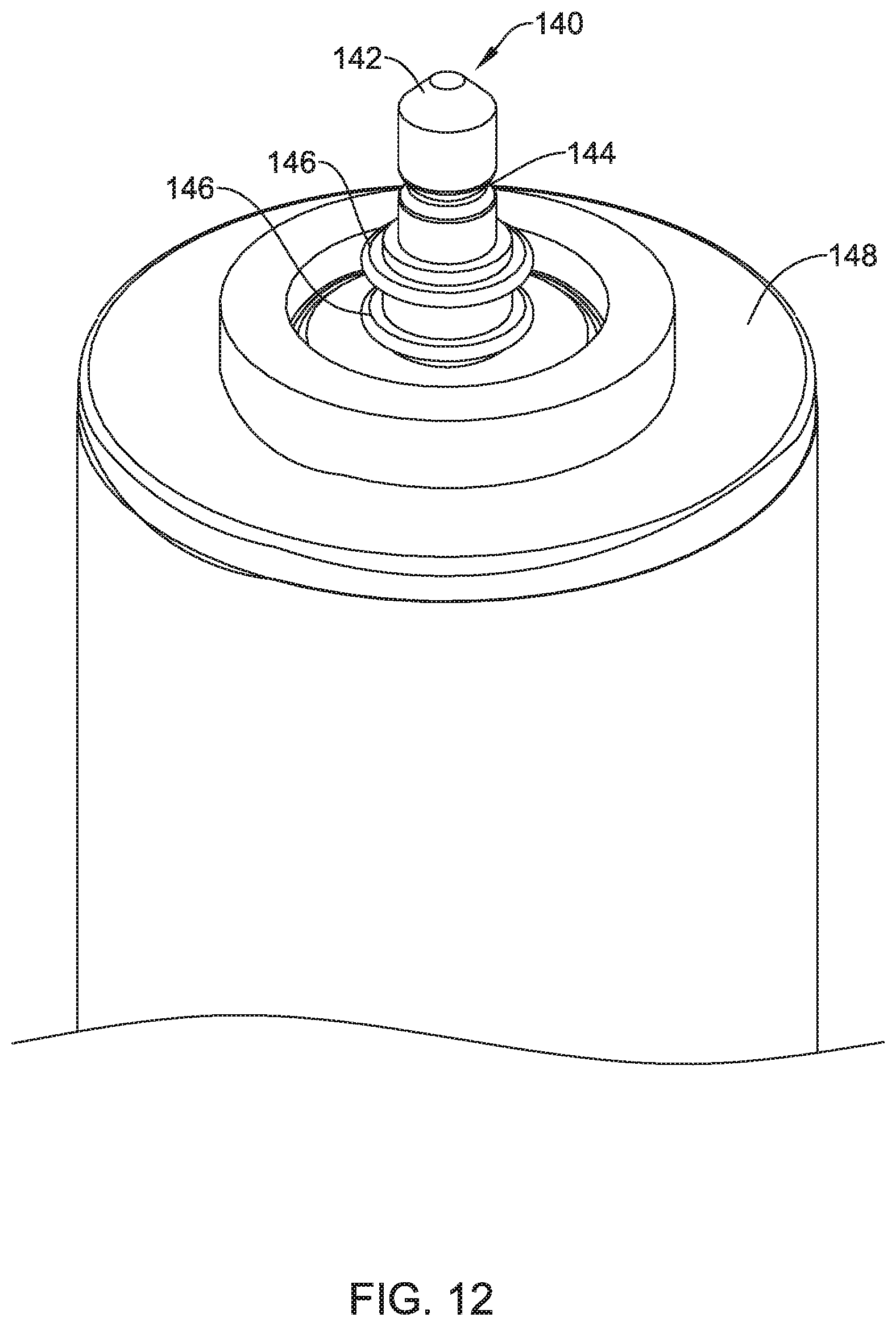
D00013

D00014

D00015

D00016

XML
uspto.report is an independent third-party trademark research tool that is not affiliated, endorsed, or sponsored by the United States Patent and Trademark Office (USPTO) or any other governmental organization. The information provided by uspto.report is based on publicly available data at the time of writing and is intended for informational purposes only.
While we strive to provide accurate and up-to-date information, we do not guarantee the accuracy, completeness, reliability, or suitability of the information displayed on this site. The use of this site is at your own risk. Any reliance you place on such information is therefore strictly at your own risk.
All official trademark data, including owner information, should be verified by visiting the official USPTO website at www.uspto.gov. This site is not intended to replace professional legal advice and should not be used as a substitute for consulting with a legal professional who is knowledgeable about trademark law.