Method for suppressing common-mode current of neutral line in T-type three-level three-phase inverter
Huang , et al.
U.S. patent number 10,734,915 [Application Number 16/496,618] was granted by the patent office on 2020-08-04 for method for suppressing common-mode current of neutral line in t-type three-level three-phase inverter. This patent grant is currently assigned to JIANGSU GOODWE POWER SUPPLY TECHNOLOGY CO., LTD.. The grantee listed for this patent is GOODWE POWER SUPPLY TECHNOLOGY CO., LTD. Invention is credited to Gang Fang, Min Huang, Jinjun Lu, Shengren Xie, Yong Yang.


View All Diagrams
| United States Patent | 10,734,915 |
| Huang , et al. | August 4, 2020 |
Method for suppressing common-mode current of neutral line in T-type three-level three-phase inverter
Abstract
Provided is a method for suppressing common-mode current of neutral line in T-type three-level three-phase inverter, the method of the present disclosure can effectively suppress LC filter resonance contained in the currents of a circulation neutral line and inversion side of a inverter, reduce the common-mode leakage current of the inverter, and improve the performance of the inverter.
| Inventors: | Huang; Min (Jiangsu, CN), Yang; Yong (Jiangsu, CN), Fang; Gang (Jiangsu, CN), Lu; Jinjun (Jiangsu, CN), Xie; Shengren (Jiangsu, CN) | ||||||||||
|---|---|---|---|---|---|---|---|---|---|---|---|
| Applicant: |
|
||||||||||
| Assignee: | JIANGSU GOODWE POWER SUPPLY
TECHNOLOGY CO., LTD. (CN) |
||||||||||
| Family ID: | 59339629 | ||||||||||
| Appl. No.: | 16/496,618 | ||||||||||
| Filed: | March 23, 2018 | ||||||||||
| PCT Filed: | March 23, 2018 | ||||||||||
| PCT No.: | PCT/CN2018/080349 | ||||||||||
| 371(c)(1),(2),(4) Date: | September 23, 2019 | ||||||||||
| PCT Pub. No.: | WO2018/171766 | ||||||||||
| PCT Pub. Date: | September 27, 2018 |
Prior Publication Data
| Document Identifier | Publication Date | |
|---|---|---|
| US 20200021204 A1 | Jan 16, 2020 | |
Foreign Application Priority Data
| Mar 24, 2017 [CN] | 2017 1 0180367 | |||
| Current U.S. Class: | 1/1 |
| Current CPC Class: | H02M 7/5395 (20130101); H02M 7/487 (20130101); Y02E 10/56 (20130101); H02M 2001/123 (20130101); H02M 1/12 (20130101); Y02B 70/10 (20130101); H02M 7/483 (20130101) |
| Current International Class: | H02M 7/5395 (20060101); H02M 7/487 (20070101); H02M 1/12 (20060101); H02M 7/483 (20070101) |
References Cited [Referenced By]
U.S. Patent Documents
| 6333569 | December 2001 | Kim |
| 7355865 | April 2008 | Royak |
| 9853573 | December 2017 | Siri |
| 10236793 | March 2019 | Lung |
| 2008/0298103 | December 2008 | Bendre et al. |
| 2012/0262957 | October 2012 | Yamada |
| 2019/0229646 | July 2019 | Liu |
| 102624266 | Aug 2012 | CN | |||
| 102723889 | Oct 2012 | CN | |||
| 103746584 | Apr 2014 | CN | |||
| 104811071 | Jul 2015 | CN | |||
| 105553309 | May 2016 | CN | |||
| 106981976 | Jul 2017 | CN | |||
Other References
|
International Search Report dated Jul. 2, 2018 for PCT/CN2018/080349. cited by applicant. |
Primary Examiner: Ahmed; Yusef A
Assistant Examiner: Ahmad; Shahzeb K
Attorney, Agent or Firm: Schmeiser, Olsen & Watts, LLP
Claims
The invention claimed is:
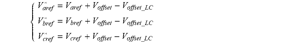
1. A method for suppressing a common-mode current of neutral line in a T-type three-level three-phase inverter, being applied to the T-type three-level three-phase inverter adopting sine-wave pulse width modulation (SPWM) and outputting three-phase current signals i.sub.a, i.sub.b and i.sub.c on an inversion side, an output of the T-type three-level three-phase inverter being connected to a power grid via an LC filter, wherein the method comprising: adopting .times..times..times..times..times..times. ##EQU00009## as a modulation signal for modulating the T-type three-level three-phase inverter; wherein, V.sub.aref*, V.sub.bref* and V.sub.cref* are respectively three-phase modulation signals for modulating the T-type three-level three-phase inverter, V.sub.aref, V.sub.bref and V.sub.cref are respectively three-phase conventional sine-wave pulse modulation signals, V.sub.offset is a third-harmonic bias signal of the three-phase conventional sine-wave pulse modulation signals, V.sub.offset_LC is a voltage bias signal for suppressing a resonant current of the LC filter from being injected to the modulation signal, V.sub.offset_LC=K.sub.fi.sub.a_high, further wherein, K.sub.f is a conversion coefficient for converting current into voltage, and i.sub.a_high is a high-frequency component of an output current i.sub.a of the inversion side of the T-type three-level three-phase inverter.
2. The method according to claim 1, wherein the output current i.sub.a of the inversion side of the T-type three-level three-phase inverter passes through a low-pass filter to obtain a high-frequency current i.sub.a_low, thereof, i.sub.a_high=i.sub.a-i.sub.a_low.
3. The method according to claim 2, wherein .times..times..omega..omega..times. ##EQU00010## and, .omega..sub.f is a cut-off frequency of the low-pass filter, and S is a Laplace transform operator.
4. The method according to claim 1, wherein V.sub.offset_LC=-(max(V.sub.aref,V.sub.bref,V.sub.cref)+min(V.sub.aref,V.- sub.bref,V.sub.cref)/2.
5. The method for according to claim 1, further comprising converting the three-phase current signals i.sub.a, i.sub.b and i.sub.c outputted by the inversion side of the T-type three-level three-phase inverter respectively into corresponding DC components i.sub.d and i.sub.q in dq coordinate system through coordinate transformation, and after comparing the corresponding DC components i.sub.d and i.sub.q of the three-phase current signals with given values i.sub.d* and i.sub.q* respectively, and then outputting adjusted outputs through a proportional-integral regulator, and then obtaining three-phase conventional sine-wave pulse modulation signals V.sub.aref, V.sub.bref and V.sub.cref after the adjusted outputs finish the coordinate transformation.
6. The method according to claim 5, wherein during coordinate transformation, obtaining a spatial angle of the power grid via a phase locked loop.
7. The method according to claim 1, wherein the T-type three-level three-phase inverter adopts a vector control mode of grid voltage orientation.
Description
CROSS-REFERENCE TO RELATED APPLICATIONS
This application claims priority to PCT Application No. PCT/CN2018/080349, having a filing date of Mar. 23, 2018, which is based on Chinese Application No. 201710180367.X, having a filing date of Mar. 24, 2017, the entire contents both of which are hereby incorporated by reference.
FIELD OF TECHNOLOGY
The following relates to a method for suppressing a common-mode current of neutral line in T-type three-level three-phase inverter.
BACKGROUND
In a distributed power generation system, the inverter acts as a bridge connecting the renewable energy (such as photovoltaic power generation, wind power generation, etc.) with the power grid or load, and its performance directly affects the entire distributed power generation system. The multi-level inverter in the distributed power generation system has the following advantages compared with the two-level inverter: (1) the inverter output voltage and current harmonics are smaller; (2) the output voltage change rate is smaller; and (3) the output power is larger. Therefore, multi-level inverters have received attention and applications in distributed power generation systems.
In a multi-level inverter, the T-type three-level three-phase inverter has the following advantages compared with a diode-clamped three-level three-phase inverter: (1) reducing six power diodes, thereby reducing system cost; (2) having an inverter switching frequency in 5 kHz-30 kHz, therefore the T-type three-level three-phase inverter is more efficient than the diode-clamped three-level three-phase inverter. Therefore, T-type three-level inverters have been widely used in distributed power generation systems.
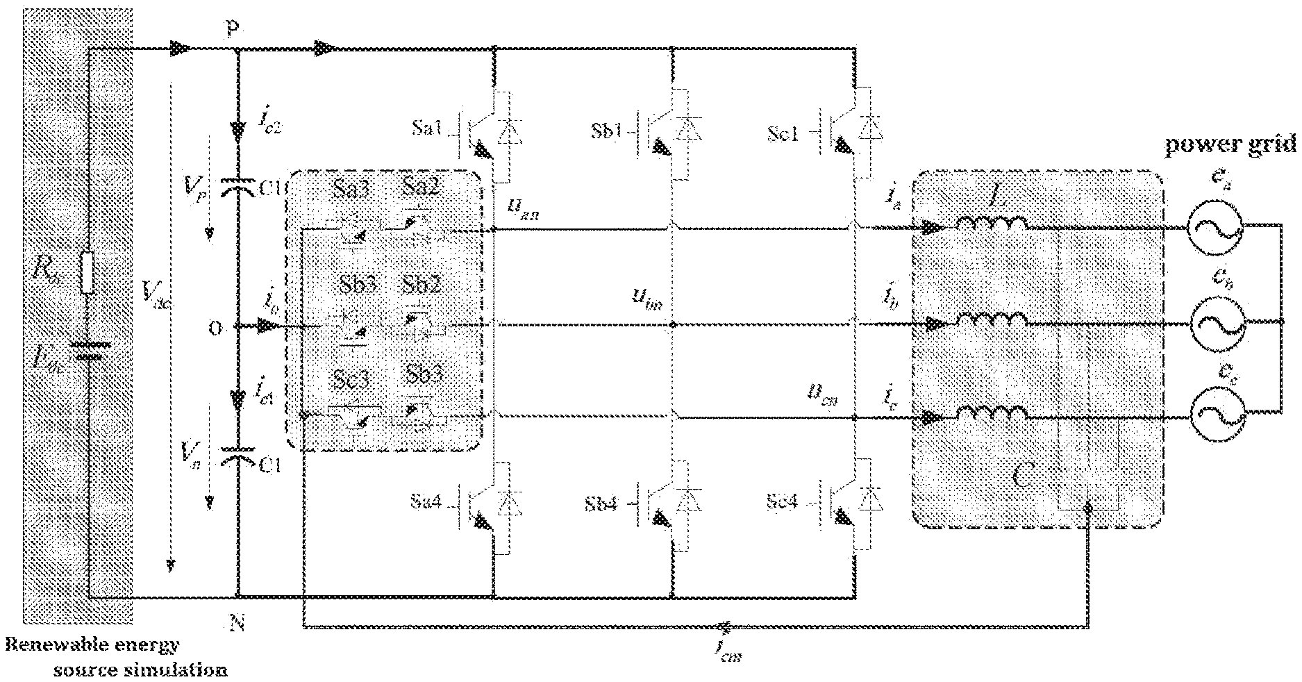
In photovoltaic power generation systems, inverters can be divided into isolated and non-isolated inverters, and non-isolated inverters are widely used in distributed photovoltaic power generation systems due to their advantages such as high efficiency and small size. For the non-isolated T-type three-level three-phase photovoltaic grid-connected inverters, in order to reduce the common-mode leakage current of photovoltaic grid-connected inverters, most commercial inverters usually adopt a scheme of connecting the common point of the output filter capacitor of the T-type three-level three-phase inverter to the neutral point (the circulation neutral line) of the DC bus capacitor, as shown in FIG. 1. In this way, a part of the high-frequency current of the inverter will be circulated in the neutral line, which greatly reduces the output common-mode leakage current of the inverter. However, due to the presence of the circulation neutral line of the inverter, the high-frequency component of resonance formed by the LC filter of the T-type three-level three-phase inverter will also flow in the inverter and the neutral line, affecting the currents in the inversion side and the circulation neutral line of the photovoltaic grid-connected inverter, causing the current of the output inversion side and the circulation neutral line of the photovoltaic grid-connected inverter current to contain the resonant current of the LC filter. Therefore, if uncontrolled, the high-frequency current of the circulation neutral line and the high-frequency component of the current of the inversion side will increase.
For most commercial photovoltaic grid-connected inverters, the resonant current of the LC filter is not considered. The main reason is that the resonant current of the LC filter mainly circulates on the inversion side and the circulation neutral line, and does not flow in the inverter grid side (will not flow into the grid). It can be seen that in order to suppress the high-frequency current of the circulation neutral line in the T-type three-level three-phase grid-connected inverter and the resonant high-frequency current of the inversion side of the inverter, a method for suppressing the current of the circulation neutral line in the T-type three-level three-phase photovoltaic grid-connected inverter to improve the performance of the T-type three-level three-phase photovoltaic grid-connected inverter has a good application prospect in the distributed power generation systems.
SUMMARY
An aspect relates to providing a method for suppressing a common-mode current of neutral line in a T-type three-level three-phase inverter, which can suppress a common-mode current of neutral line in a grid-connected inverter to improve the performance of the inverter.
The method for suppressing a common-mode current of neutral line in a T-type three-level three-phase inverter, is applied to a T-type three-level three-phase inverter adopting SPWM modulation and outputting three-phase current signals i.sub.a, i.sub.b and i.sub.c on an inversion side, the output of the T-type three-level three-phase inverter being connected to a power grid via an LC filter, and the method for suppressing a common-mode current of neutral line in a T-type three-level three-phase inverter is: adopting
.times..times..times..times..times..times. ##EQU00001##
as a modulation signal for modulating the T-type three-level three-phase inverter;
wherein, V.sub.aref*, V.sub.bref* and V.sub.cref* are respectively three-phase modulation signals for modulating the T-type three-level three-phase inverter, V.sub.aref, V.sub.bref and V.sub.cref are respectively three-phase conventional sine-wave pulse modulation signals, V.sub.offset is a third-harmonic bias signal of the three-phase conventional sine-wave pulse modulation signals, V.sub.offset_LC is a voltage bias signal for suppressing a resonant current of the LC filter from being injected to the modulation signal, V.sub.offset_LC=K.sub.fi.sub.a_high, K.sub.f is a conversion coefficient for converting current into voltage, and i.sub.a_high is a high-frequency component of an output current i.sub.a of the inversion side of the T-type three-level three-phase inverter.
The output current i.sub.a of the inversion side of the T-type three-level three-phase inverter passes through a low-pass filter to obtain a high-frequency current i.sub.a_low, thereof, i.sub.a_high=i.sub.a-i.sub.a_low.
.times..times..omega..omega..times. ##EQU00002## wherein, .omega..sub.f is a cut-off frequency of the low-pass filter, and S is a Laplace transform operator. V.sub.offset_LC=-(max(V.sub.aref,V.sub.bref,V.sub.cref)+min(V.sub.aref,V.- sub.bref,V.sub.cref))/2.
The three-phase current signals i.sub.a, i.sub.b and i.sub.c outputted by the inversion side of the T-type three-level three-phase inverter are respectively converted into corresponding DC components i.sub.d and i.sub.q in the dq coordinate system through coordinate transformation, then the corresponding DC components i.sub.d and i.sub.q of the three-phase current signals are compared with given values i.sub.d* and i.sub.q* respectively, and then adjusted outputs through a proportional-integral regulator are output. Three-phase conventional sine-wave pulse modulation signals V.sub.aref, V.sub.bref and V.sub.cref are obtained after the adjusted outputs finish the coordinate transformation.
During the coordinate transformation, a spatial angle of the power grid is obtained via a phase locked loop.
The T-type three-level three-phase inverter adopts a vector control mode of grid voltage orientation.
Due to the use of the above technical solutions, the present disclosure has the following advantages over the prior art: The method of the present disclosure can effectively suppress LC filter resonance contained in the currents of a circulation neutral line and the inversion side of the inverter, reduce the common-mode leakage current of the inverter, and improve the performance of the inverter.
BRIEF DESCRIPTION
Some of the embodiments will be described in detail, with references to the following Figures, wherein like designations denote like members, wherein:
FIG. 1 is a schematic diagram of a resonant current flow loop of an LC filter in a distributed power generation inverter system;
FIG. 2 is a schematic structural diagram of a distributed power generation inverter system;
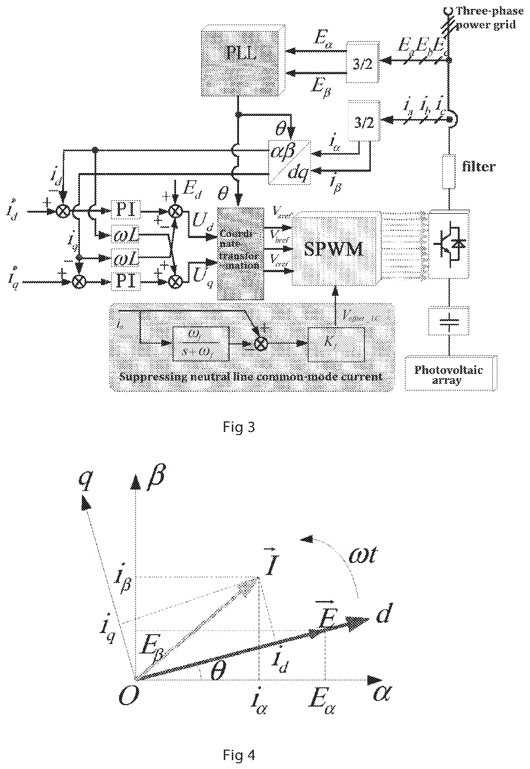
FIG. 3 is a schematic diagram of a vector control method for grid voltage orientation of a three-phase grid-connected inverter to suppress the common-mode current in a circulation neutral line;
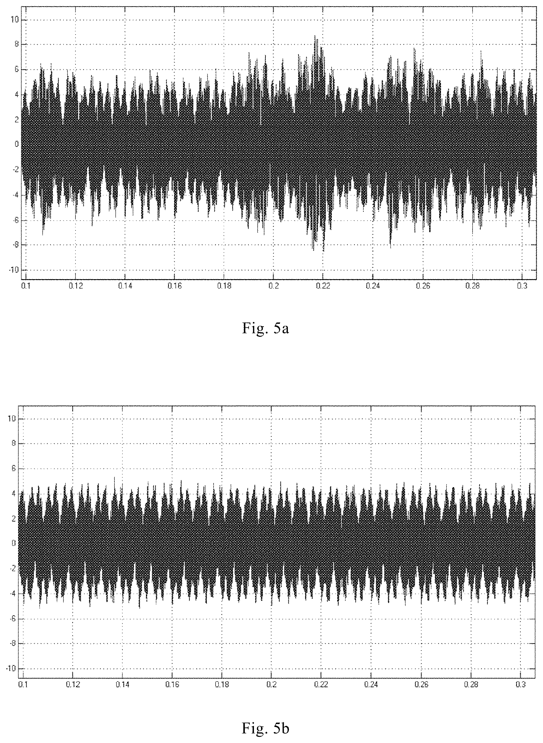
FIG. 4 is a vector diagram of a vector control system based on grid voltage orientation;
FIG. 5a is a steady-state simulation waveform diagrams of three-phase grid-connected inverters for the circulation neutral line current in a conventional method;
FIG. 5b is a steady-state simulation waveform diagrams of three-phase grid-connected inverters for the circulation neutral line current in the method of the present disclosure;
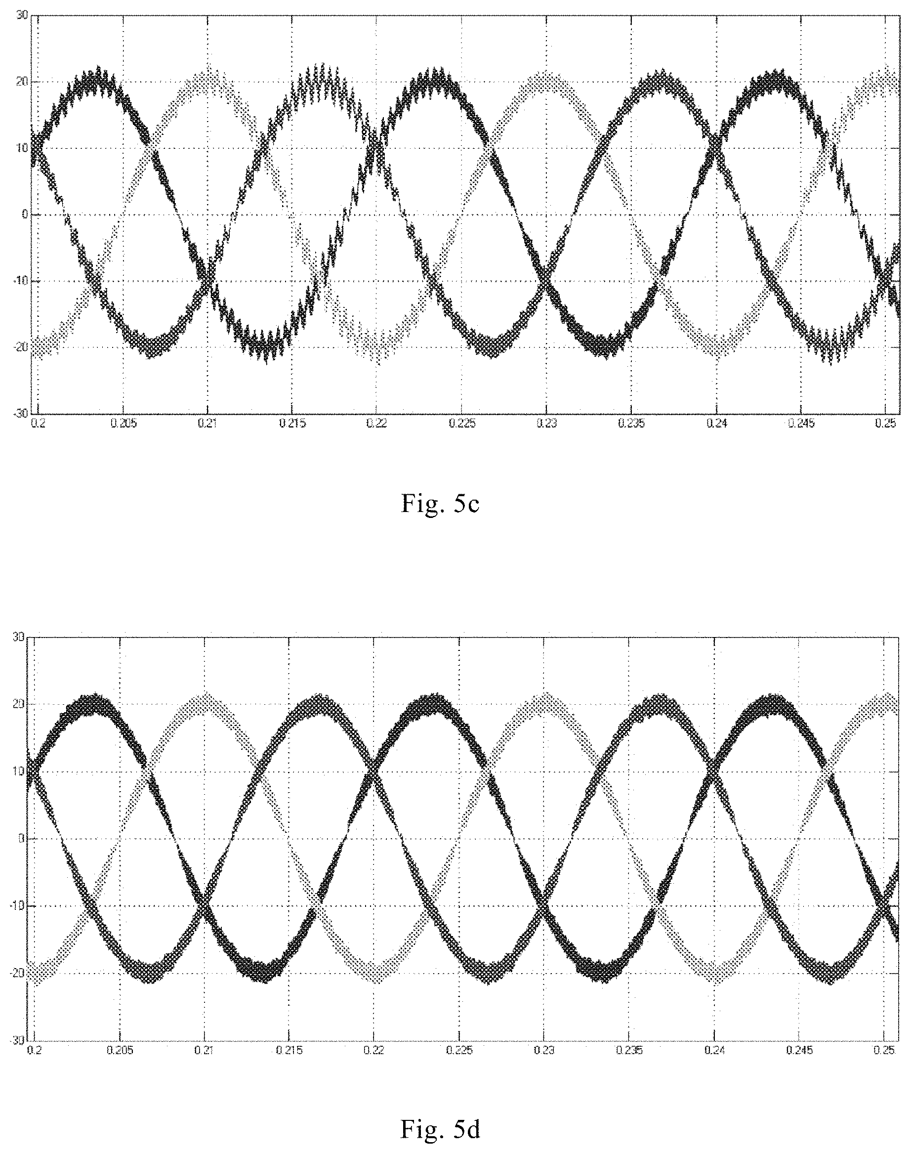
FIG. 5c is a steady-state simulation waveform diagrams of three-phase grid-connected inverters for the three-phase currents of the inversion side in a conventional method;
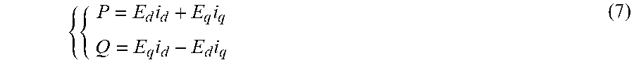
FIG. 5d is a steady-state simulation waveform diagrams of three-phase grid-connected inverters for the three-phase currents of the inversion side in the method of the present disclosure;
FIG. 5e is a steady-state simulation waveform diagrams of three-phase grid-connected inverters for the three-phase currents on the grid side in a conventional method; and
FIG. 5f is a steady-state simulation waveform diagrams of three-phase grid-connected inverters for the three-phase currents on the grid side in the method of the disclosure
DETAILED DESCRIPTION
In the following, the present disclosure is further explained in detail combining with the embodiments shown in the accompanying drawings.
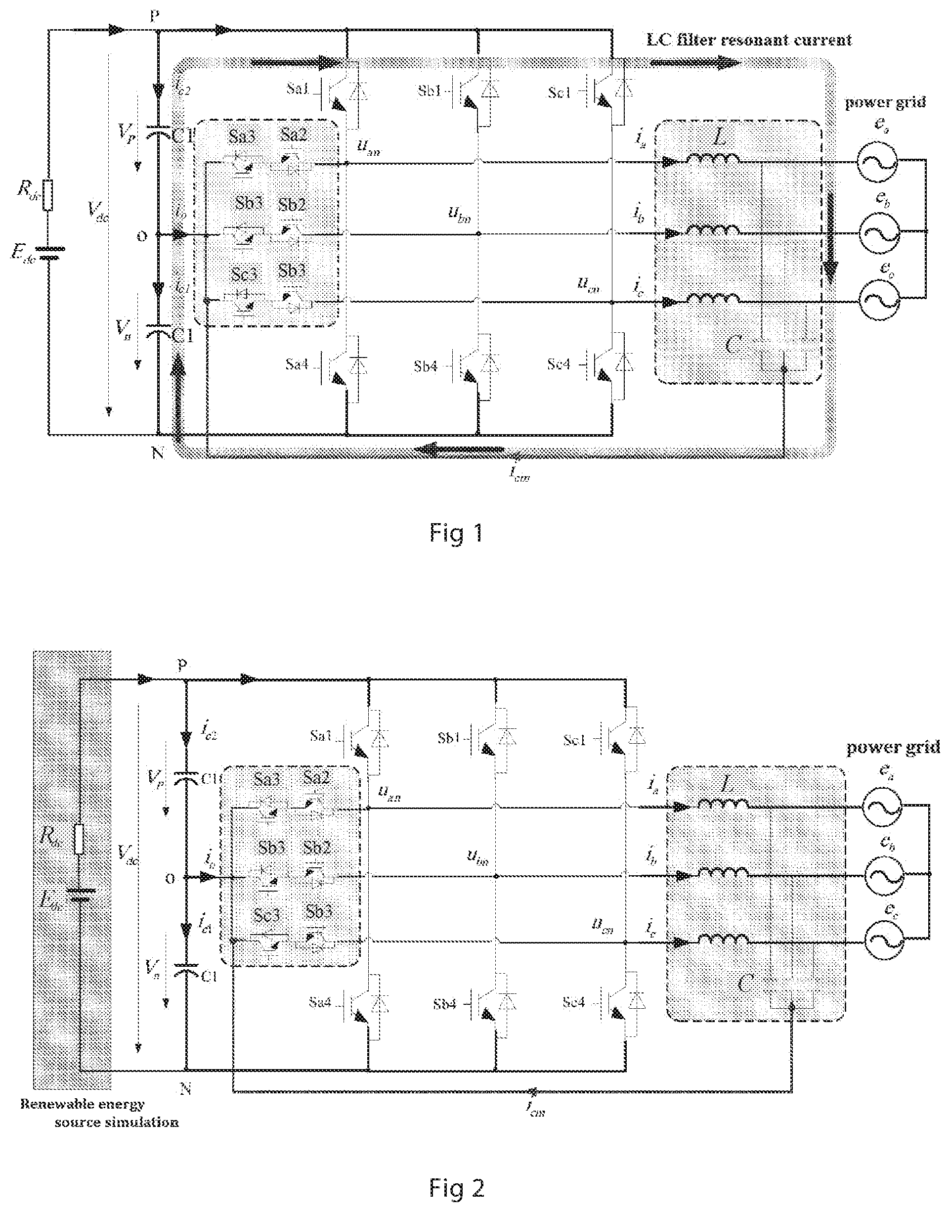
As shown in FIG. 2, a distributed power generation inverter system consists of distributed renewable energy source, a T-type three-level three-phase inverter, a LC filter, the power grid and the like. In this embodiment, the distributed power generation inverter system is a photovoltaic power generation inverter system, wherein the distributed renewable energy source is a photovoltaic array, which, in FIG. 2, is equivalent to the DC power source E.sub.dc and the DC input resistance R.sub.dc. The T-type three-level three-phase inverter realizes active power and reactive power control according to the input power of the photovoltaic array, and the LC filter filters out the high-frequency component of the inverter output current, and the output of the T-type three-level three-phase inverter is connected to the power grid via the LC filter. In FIG. 2, u.sub.an, u.sub.bn and u.sub.on are respectively three-phase voltages output by the T-type three-level three-phase grip-connected inverter, e.sub.a, e.sub.b, and e.sub.c are respectively three-phase grip voltages, i.sub.a, i.sub.b and i.sub.c are respectively three-phase output currents output by the inversion side of the T-type three-level three-phase inverter, L is the filter inductance, and C is filter capacitance. The common point of the output filter capacitor C of the T-type three-level three-phase inverter is connected to the neutral point (the circulation neutral line) of the DC bus capacitor.
The above-mentioned T-type three-level three-phase inverter adopts SPWM modulation. In order to increase the utilization of the DC bus voltage, a third harmonic is generally added to the conventional sine-wave pulse width modulation (SPWM). After adding the third harmonic, the modulation signals of the inverter are:
##EQU00003##
wherein, V.sub.aref, V.sub.bref and V.sub.cref are respectively three-phase conventional sine-wave pulse modulation signals, V.sub.offset is a third-harmonic bias signal of the three-phase conventional sine-wave pulse modulation signals, and the third-harmonic bias signal V.sub.offset is expressed as: V.sub.offset_LC=-(max(V.sub.aref,V.sub.bref,V.sub.cref)+min(V.sub.aref,V.- sub.bref,V.sub.cref))/2 (2)
wherein, the max function takes the maximum value of the variables, and wherein, the min function takes the minimum value of the variables.
In order to suppress the LC filter resonant current from flowing in the circulation neutral line, the T-type three-level three-phase inverter generates a resonant current to offset it. First, the inversion-side current i.sub.a of the T-type three-level three-phase grid-connected inverter is passed through a low-pass filter to obtain the low-frequency current i.sub.a_low of the inverter Phase-A current, which can be expressed as:
.times..times..omega..omega..times. ##EQU00004##
wherein, .omega..sub.f is a cut-off frequency of the low-pass filter, and in the present system, .omega..sub.f is selected to be .omega..sub.f=314.15 rad/s, and S is a Laplace transform operator.
Then, the high-frequency component current i.sub.a_high of the three-level three-phase inversion-side current i.sub.a is: i.sub.a_high=i.sub.a-i.sub.a_low (4)
Then, the voltage bias signal for suppressing a resonant current of the LC filter from being injected to the modulation signal is: V.sub.offset_LC=K.sub.fi.sub.a_high (5)
wherein, K.sub.f is a conversion coefficient for converting current into voltage, in the system of the present disclosure, K.sub.f=4.
Therefore, the following modulation signal having a suppression of a common-mode current of the circulation neutral line is adopted as a modulation signal for modulating the T-type three-level three-phase inverter:
.times..times..times..times..times..times. ##EQU00005##
wherein, V.sub.aref*, V.sub.bref* and V.sub.cref* are respectively three-phase modulation signals for modulating the T-type three-level three-phase inverter, V.sub.aref, V.sub.bref and V.sub.cref are respectively three-phase conventional sine-wave pulse modulation signals, V.sub.offset is a third-harmonic bias signal of the three-phase conventional sine-wave pulse modulation signals, and V.sub.offset_LC is a voltage bias signal for suppressing a resonant current of the LC filter from being injected to the modulation signal.
A schematic diagram of a vector control method for grid voltage orientation of a three-phase grid-connected inverter to suppress a common-mode current of a circulation neutral line based on the above mentioned control method is shown in FIG. 3. The three-phase current signals i.sub.a, i.sub.b and i.sub.c outputted by the inversion side of the T-type three-level three-phase inverter are respectively converted into corresponding DC components i.sub.d and i.sub.q in the dq coordinate system through coordinate transformation (ABC/.alpha..beta./dg transformation), and after the corresponding DC components i.sub.d and i.sub.q of the three-phase current signals are respectively compared with given values i.sub.d* and i.sub.q* (the given values i.sub.d* and i.sub.q* are freely given according to the power level, for example, in the present system, they are given as i.sub.d*=20 A, and i.sub.q*=0 A), and then adjusted outputs through a proportional-integral (PI) regulator are output. Three-phase conventional sine-wave pulse modulation signals V.sub.aref, V.sub.bref and V.sub.cref are obtained after the adjusted outputs go through the coordinate transformation (ABC/.alpha..beta./dg transformation). In order to obtain the spatial angle of the power grid, the spatial angle of the power grid is obtained via a phase locked loop (PLL) during coordinate transformation. And in order to suppress the common-mode current of the circulation neutral line, the inversion-side current i.sub.a is filtered and converted to obtain V.sub.offset_LC, and then obtain the required three-phase modulation signals V.sub.aref*, V.sub.bref* and V.sub.cref*.
In order to realize independent control of active power and reactive power of the T-type three-level three-phase grid-connected inverter, the T-type three-level three-phase inverter adopts a vector control mode of grid voltage orientation. The vector control mode of grid voltage orientation (Voltage Oriented Control, VOC) means that the dq synchronous rotating coordinate system is rotated synchronously with the three-phase grid voltage space vector {right arrow over (E)}, and the d-axis of the dq rotating coordinate system coincides with the voltage vector {right arrow over (E)}. A vector diagram of a vector control system based on grid voltage orientation is shown in FIG. 4.
It can be seen from FIG. 4 that a component of the three-phase grid voltage vector {right arrow over (E)} on the d-axis of the dq rotating coordinate system is E.sub.d=|{right arrow over (E)}|, and a component on the q-axis is E.sub.q=0. According to the instantaneous power theory, the instantaneous active power P and instantaneous reactive power Q output by the three-phase grid-connected inverter are respectively:
.times..times..times..times. ##EQU00006##
wherein, E.sub.d and E.sub.q are respectively the d-component and q-component of the grid voltage within the dq rotating coordinate system; and i.sub.d and i.sub.q are respectively the d-component and q-component of the three-phase grid-connected inverter output current within the dq rotating coordinate system.
Set the grid voltage on the d-axis, then
##EQU00007##
Connect Formula (7) and Formula (8) to obtain:
.times..times. ##EQU00008##
From Formula (9), it can be seen that the instantaneous active power P of the system is proportional to the d-component i.sub.d of the inverter output current, while the instantaneous reactive power Q is proportional to the q-component i.sub.q of the output current. Therefore, through the control of the i.sub.d and i.sub.q, the instantaneous active power and reactive power of the system can be separately controlled.
In order to verify the correctness and effectiveness of the above-mentioned method of the present disclosure, the method of the present disclosure and the conventional method were simulated and compared according to the control method of FIG. 3. System simulation parameters are shown in Table 1.
TABLE-US-00001 TABLE 1 Simulation parameters Rated power P = 10 kW Filter inductance L = 1.3 mH Filter capacitance C = 4.7 .mu.F BUS filter capacitance C.sub.1 = 3000 .mu.F Inverter switching frequency f.sub.s = 20 kHz DC input E.sub.dc = 650 V DC input resistance R.sub.dc = 1 .OMEGA. Power grid voltage frequency f.sub.g = 50 Hz Power grid voltage effective value e.sub.RMS = 220 V
In order to achieve an inversion with power factor of 1, active power current is given as i.sub.d*=20 A, reactive power current are given as i.sub.q*=0 A, and FIG. 5 shows the circulation neutral line currents, the inversion side three-phase currents and grid-side three-phase currents of the inverter outputs, wherein, FIGS. 5(a), 5(c) and 5(e) adopt the conventional method, and FIGS. 5(b), 5(d) and 5(f) adopt the method of the present disclosure. It can be seen from the simulation waveforms of FIG. 5 that: (1) the maximum value of the circulation neutral line current i.sub.on in the method of the present disclosure is 5 A, and the maximum value of the neutral line current i.sub.on in the conventional method is 9 A, and the circulation neutral line current output in the method of the present disclosure is significantly smaller than that in the conventional method; (2) the waveform quality of the inversion-side current output in the method of the present disclosure is superior to that in the conventional method, and the inversion-side current in the conventional method obviously includes the high frequency resonant current of the LC filter; (3) the grid-side currents of the inverters in the method of the present disclosure and the conventional method are basically the same. By comparing simulation waveforms in FIG. 5, it can be seen that: the method of the present disclosure can effectively suppress LC filter resonance contained in the currents of the circulation neutral line and the inversion side of the inverter, and improve the performance of the inverter, on basis of not increasing in any hardware. It has good application value in photovoltaic power generation system.
The embodiments provide a method for suppressing the resonant current of the LC filter in the T-type three-level three-phase photovoltaic grid-connected inverter and suppressing the common-mode current of the neutral line, which greatly reduces the high-frequency component of the common-mode current of the neutral line of the inverter, and is applied in the T-type three-level three-phase photovoltaic grid-connected power generation system, and improves the performance of the T-type three-level three-phase photovoltaic grid-connected inverter and the performance of the photovoltaic grid-connected power generation system.
The embodiments described above are only for illustrating the technical concepts and features of the present disclosure, and are intended to make those skilled in the art being able to understand the present disclosure and thereby implement it, and should not be concluded to limit the protective scope of this disclosure. Any equivalent variations or modifications according to the spirit of the present disclosure should be covered by the protective scope of the present disclosure.
Although the present invention has been disclosed in the form of preferred embodiments and variations thereon, it will be understood that numerous additional modifications and variations could be made thereto without departing from the scope of the invention.
For the sake of clarity, it is to be understood that the use of `a` or `an` throughout this application does not exclude a plurality, and `comprising` does not exclude other steps or elements.
* * * * *
D00000
D00001
D00002
D00003
D00004
D00005
M00001
M00002
M00003
M00004
M00005
M00006
M00007
M00008
M00009
M00010

XML
uspto.report is an independent third-party trademark research tool that is not affiliated, endorsed, or sponsored by the United States Patent and Trademark Office (USPTO) or any other governmental organization. The information provided by uspto.report is based on publicly available data at the time of writing and is intended for informational purposes only.
While we strive to provide accurate and up-to-date information, we do not guarantee the accuracy, completeness, reliability, or suitability of the information displayed on this site. The use of this site is at your own risk. Any reliance you place on such information is therefore strictly at your own risk.
All official trademark data, including owner information, should be verified by visiting the official USPTO website at www.uspto.gov. This site is not intended to replace professional legal advice and should not be used as a substitute for consulting with a legal professional who is knowledgeable about trademark law.