Adapter, extension, and connector assemblies for surgical devices
Cabrera , et al.
U.S. patent number 10,729,443 [Application Number 15/238,049] was granted by the patent office on 2020-08-04 for adapter, extension, and connector assemblies for surgical devices. This patent grant is currently assigned to Covidien LP. The grantee listed for this patent is Covidien LP. Invention is credited to Ramiro Cabrera, Justin Williams.


View All Diagrams
| United States Patent | 10,729,443 |
| Cabrera , et al. | August 4, 2020 |
Adapter, extension, and connector assemblies for surgical devices
Abstract
A surgical assembly for operably connecting an end effector to an electrosurgical instrument includes an adapter assembly and an extension assembly. The adapter assembly includes a drive coupling assembly, a drive transfer assembly operably received through the drive coupling assembly and including a first rotatable shaft, and a first pusher assembly operably connected to the first rotatable shaft for converting rotational motion from the first rotatable shaft to longitudinal movement to perform a first function. The first pusher assembly includes a first pusher member having an outer housing formed of a first material, and a threaded insert formed of a second material and disposed within the outer housing. The extension assembly is operably connected to a distal end of the adapter assembly, and includes a flexible band assembly operably connectable to the first pusher member of the first pusher assembly.
| Inventors: | Cabrera; Ramiro (Cheshire, CT), Williams; Justin (Southbury, CT) | ||||||||||
|---|---|---|---|---|---|---|---|---|---|---|---|
| Applicant: |
|
||||||||||
| Assignee: | Covidien LP (Mansfield,
MA) |
||||||||||
| Family ID: | 1000004961855 | ||||||||||
| Appl. No.: | 15/238,049 | ||||||||||
| Filed: | August 16, 2016 |
Prior Publication Data
| Document Identifier | Publication Date | |
|---|---|---|
| US 20160354088 A1 | Dec 8, 2016 | |
Related U.S. Patent Documents
| Application Number | Filing Date | Patent Number | Issue Date | ||
|---|---|---|---|---|---|
| 14875766 | Oct 6, 2015 | 10226254 | |||
| 62066518 | Oct 21, 2014 | ||||
| 62251930 | Nov 6, 2015 | ||||
| Current U.S. Class: | 1/1 |
| Current CPC Class: | A61B 17/1155 (20130101); F16H 25/2056 (20130101); A61B 17/00234 (20130101); A61B 2017/00464 (20130101); A61B 2017/00473 (20130101); A61B 2017/07285 (20130101); A61B 2017/2902 (20130101); A61B 2017/2905 (20130101); F16H 2025/2087 (20130101); A61B 2017/2923 (20130101); A61B 2017/00477 (20130101) |
| Current International Class: | A61B 17/29 (20060101); A61B 17/115 (20060101); F16H 25/20 (20060101); A61B 17/00 (20060101); A61B 17/072 (20060101) |
References Cited [Referenced By]
U.S. Patent Documents
| 2777340 | January 1957 | Hettwer et al. |
| 2957353 | October 1960 | Babacz |
| 3111328 | November 1963 | Di Rito et al. |
| 3695058 | October 1972 | Keith, Jr. |
| 3734515 | May 1973 | Dudek |
| 3759336 | September 1973 | Marcovitz et al. |
| 4162399 | July 1979 | Hudson |
| 4606343 | August 1986 | Conta et al. |
| 4705038 | November 1987 | Sjostrom et al. |
| 4722685 | February 1988 | de Estrada et al. |
| 4823807 | April 1989 | Russell et al. |
| 4874181 | October 1989 | Hsu |
| 5129118 | July 1992 | Walmesley |
| 5129570 | July 1992 | Schulze et al. |
| 5152744 | October 1992 | Krause et al. |
| 5301061 | April 1994 | Nakada et al. |
| 5312023 | May 1994 | Green et al. |
| 5326013 | July 1994 | Green et al. |
| 5350355 | September 1994 | Sklar |
| 5383874 | January 1995 | Jackson et al. |
| 5383880 | January 1995 | Hooven |
| 5389098 | February 1995 | Tsuruta et al. |
| 5395033 | March 1995 | Byrne et al. |
| 5400267 | March 1995 | Denen et al. |
| 5411508 | May 1995 | Bessler et al. |
| 5413267 | May 1995 | Solyntjes et al. |
| 5427087 | June 1995 | Ito et al. |
| 5433721 | July 1995 | Hooven et al. |
| 5467911 | November 1995 | Tsuruta et al. |
| 5476379 | December 1995 | Disel |
| 5487499 | January 1996 | Sorrentino et al. |
| 5518163 | May 1996 | Hooven |
| 5518164 | May 1996 | Hooven |
| 5526822 | June 1996 | Burbank et al. |
| 5529235 | June 1996 | Boiarski et al. |
| 5535934 | July 1996 | Boiarski et al. |
| 5535937 | July 1996 | Boiarski et al. |
| 5540375 | July 1996 | Bolanos et al. |
| 5540706 | July 1996 | Aust et al. |
| 5542594 | August 1996 | McKean et al. |
| 5549637 | August 1996 | Crainich |
| 5553675 | September 1996 | Pitzen et al. |
| 5562239 | October 1996 | Boiarski et al. |
| 5564615 | October 1996 | Bishop et al. |
| 5609560 | March 1997 | Ichikawa et al. |
| 5626587 | May 1997 | Bishop et al. |
| 5632432 | May 1997 | Schulze et al. |
| 5645209 | July 1997 | Green et al. |
| 5647526 | July 1997 | Green et al. |
| 5653374 | August 1997 | Young et al. |
| 5658300 | August 1997 | Bito et al. |
| 5662662 | September 1997 | Bishop et al. |
| 5667517 | September 1997 | Hooven |
| 5693042 | December 1997 | Boiarski et al. |
| 5704534 | January 1998 | Huitema et al. |
| 5713505 | February 1998 | Huitema |
| 5762603 | June 1998 | Thompson |
| 5779130 | July 1998 | Alesi et al. |
| 5782396 | July 1998 | Mastri et al. |
| 5782397 | July 1998 | Koukline |
| 5792573 | August 1998 | Pitzen et al. |
| 5797536 | August 1998 | Smith et al. |
| 5820009 | October 1998 | Melling et al. |
| 5863159 | January 1999 | Lasko |
| 5908427 | June 1999 | McKean et al. |
| 5954259 | September 1999 | Viola et al. |
| 5964774 | October 1999 | McKean et al. |
| 5993454 | November 1999 | Longo |
| 6010054 | January 2000 | Johnson et al. |
| 6017354 | January 2000 | Culp et al. |
| 6032849 | March 2000 | Mastri et al. |
| 6045560 | April 2000 | McKean et al. |
| 6090123 | July 2000 | Culp et al. |
| 6126651 | October 2000 | Mayer |
| 6129547 | October 2000 | Cise et al. |
| 6165169 | December 2000 | Panescu et al. |
| 6239732 | May 2001 | Cusey |
| 6241139 | June 2001 | Milliman et al. |
| 6264086 | July 2001 | McGuckin, Jr. |
| 6264087 | July 2001 | Whitman |
| 6302311 | October 2001 | Adams et al. |
| 6315184 | November 2001 | Whitman |
| 6321855 | November 2001 | Barnes |
| 6329778 | December 2001 | Culp et al. |
| 6343731 | February 2002 | Adams et al. |
| 6348061 | February 2002 | Whitman |
| 6368324 | April 2002 | Dinger et al. |
| 6371909 | April 2002 | Hoeg et al. |
| 6434507 | August 2002 | Clayton et al. |
| 6443973 | September 2002 | Whitman |
| 6461372 | October 2002 | Jensen et al. |
| 6488197 | December 2002 | Whitman |
| 6491201 | December 2002 | Whitman |
| 6533157 | March 2003 | Whitman |
| 6537280 | March 2003 | Dinger et al. |
| 6610066 | August 2003 | Dinger et al. |
| 6611793 | August 2003 | Burnside et al. |
| 6645218 | November 2003 | Cassidy et al. |
| 6654999 | December 2003 | Stoddard et al. |
| 6681979 | January 2004 | Whitman |
| 6695199 | February 2004 | Whitman |
| 6698643 | March 2004 | Whitman |
| 6699177 | March 2004 | Wang et al. |
| 6716233 | April 2004 | Whitman |
| 6743240 | June 2004 | Smith et al. |
| 6783533 | August 2004 | Green et al. |
| 6792390 | September 2004 | Burnside et al. |
| 6793652 | September 2004 | Whitman et al. |
| 6817508 | November 2004 | Racenet et al. |
| 6830174 | December 2004 | Hillstead et al. |
| 6835199 | December 2004 | McGuckin, Jr. et al. |
| 6846308 | January 2005 | Whitman et al. |
| 6846309 | January 2005 | Whitman et al. |
| 6849071 | February 2005 | Whitman et al. |
| 6860892 | March 2005 | Tanaka et al. |
| 6899538 | May 2005 | Matoba |
| 6905057 | June 2005 | Swayze et al. |
| 6959852 | November 2005 | Shelton, IV et al. |
| 6964363 | November 2005 | Wales et al. |
| 6981628 | January 2006 | Wales |
| 6981941 | January 2006 | Whitman et al. |
| 6986451 | January 2006 | Mastri et al. |
| 6988649 | January 2006 | Shelton, IV et al. |
| 7032798 | April 2006 | Whitman et al. |
| RE39152 | June 2006 | Aust et al. |
| 7055731 | June 2006 | Shelton, IV et al. |
| 7059508 | June 2006 | Shelton, IV et al. |
| 7077856 | July 2006 | Whitman |
| 7111769 | September 2006 | Wales et al. |
| 7122029 | October 2006 | Koop et al. |
| 7140528 | November 2006 | Shelton, IV |
| 7141049 | November 2006 | Stern et al. |
| 7143923 | December 2006 | Shelton, IV et al. |
| 7143925 | December 2006 | Shelton, IV et al. |
| 7143926 | December 2006 | Shelton, IV et al. |
| 7147138 | December 2006 | Shelton, IV |
| 7172104 | February 2007 | Scirica et al. |
| 7225964 | June 2007 | Mastri et al. |
| 7238021 | July 2007 | Johnson |
| 7246734 | July 2007 | Shelton, IV |
| 7252660 | August 2007 | Kunz |
| 7328828 | February 2008 | Ortiz et al. |
| 7364061 | April 2008 | Swayze et al. |
| 7380695 | June 2008 | Doll et al. |
| 7380696 | June 2008 | Shelton, IV et al. |
| 7404508 | July 2008 | Smith et al. |
| 7407078 | August 2008 | Shelton, IV et al. |
| 7416101 | August 2008 | Shelton, IV et al. |
| 7419080 | September 2008 | Smith et al. |
| 7422139 | September 2008 | Shelton, IV et al. |
| 7431189 | October 2008 | Shelton, IV et al. |
| 7441684 | October 2008 | Shelton, IV et al. |
| 7448525 | November 2008 | Shelton, IV et al. |
| 7464846 | December 2008 | Shelton, IV et al. |
| 7464847 | December 2008 | Viola et al. |
| 7464849 | December 2008 | Shelton, IV et al. |
| 7481347 | January 2009 | Roy |
| 7481824 | January 2009 | Boudreaux et al. |
| 7487899 | February 2009 | Shelton, IV et al. |
| 7549564 | June 2009 | Boudreaux |
| 7565993 | July 2009 | Milliman et al. |
| 7568603 | August 2009 | Shelton, IV et al. |
| 7575144 | August 2009 | Ortiz et al. |
| 7588175 | September 2009 | Timm et al. |
| 7588176 | September 2009 | Timm et al. |
| 7637409 | December 2009 | Marczyk |
| 7641093 | January 2010 | Doll et al. |
| 7644848 | January 2010 | Swayze et al. |
| 7670334 | March 2010 | Hueil et al. |
| 7673780 | March 2010 | Shelton, IV et al. |
| 7699835 | April 2010 | Lee et al. |
| 7721931 | May 2010 | Shelton, IV et al. |
| 7738971 | June 2010 | Swayze et al. |
| 7740159 | June 2010 | Shelton, IV et al. |
| 7743960 | June 2010 | Whitman et al. |
| 7758613 | July 2010 | Whitman |
| 7766210 | August 2010 | Shelton, IV et al. |
| 7770773 | August 2010 | Whitman et al. |
| 7770775 | August 2010 | Shelton, IV et al. |
| 7793812 | September 2010 | Moore et al. |
| 7799039 | September 2010 | Shelton, IV et al. |
| 7802712 | September 2010 | Milliman et al. |
| 7803151 | September 2010 | Whitman |
| 7822458 | October 2010 | Webster, III et al. |
| 7845534 | December 2010 | Viola et al. |
| 7845537 | December 2010 | Shelton, IV et al. |
| 7857185 | December 2010 | Swayze et al. |
| 7870989 | January 2011 | Viola et al. |
| 7900805 | March 2011 | Shelton, IV et al. |
| 7905897 | March 2011 | Whitman et al. |
| 7918230 | April 2011 | Whitman et al. |
| 7922061 | April 2011 | Shelton, IV et al. |
| 7922719 | April 2011 | Ralph et al. |
| 7947034 | May 2011 | Whitman |
| 7951071 | May 2011 | Whitman et al. |
| 7954682 | June 2011 | Giordano et al. |
| 7959051 | June 2011 | Smith et al. |
| 7963433 | June 2011 | Whitman et al. |
| 7967178 | June 2011 | Soirica et al. |
| 7967179 | June 2011 | Olson et al. |
| 7992758 | August 2011 | Whitman et al. |
| 8011550 | September 2011 | Aranyi et al. |
| 8016178 | September 2011 | Olson et al. |
| 8016855 | September 2011 | Whitman et al. |
| 8016858 | September 2011 | Whitman |
| 8020743 | September 2011 | Shelton, IV |
| 8025199 | September 2011 | Whitman et al. |
| 8035487 | October 2011 | Malackowski |
| 8052024 | November 2011 | Viola et al. |
| 8114118 | February 2012 | Knodel et al. |
| 8127975 | March 2012 | Olson et al. |
| 8132705 | March 2012 | Viola et al. |
| 8152516 | April 2012 | Harvey et al. |
| 8157150 | April 2012 | Viola et al. |
| 8157151 | April 2012 | Ingmanson et al. |
| 8182494 | May 2012 | Yencho et al. |
| 8186555 | May 2012 | Shelton, IV et al. |
| 8186587 | May 2012 | Zmood et al. |
| 8220367 | July 2012 | Hsu |
| 8235273 | August 2012 | Olson et al. |
| 8241322 | August 2012 | Whitman et al. |
| 8272554 | September 2012 | Whitman et al. |
| 8292150 | October 2012 | Bryant |
| 8292888 | October 2012 | Whitman |
| 8342379 | January 2013 | Whitman et al. |
| 8348130 | January 2013 | Shah et al. |
| 8348855 | January 2013 | Hillely et al. |
| 8353440 | January 2013 | Whitman et al. |
| 8357144 | January 2013 | Whitman et al. |
| 8365633 | February 2013 | Simaan et al. |
| 8365972 | February 2013 | Aranyi et al. |
| 8371492 | February 2013 | Aranyi et al. |
| 8372057 | February 2013 | Cude et al. |
| 8391957 | March 2013 | Carlson et al. |
| 8403926 | March 2013 | Nobis et al. |
| 8418904 | April 2013 | Wenchell et al. |
| 8424739 | April 2013 | Racenet et al. |
| 8454585 | June 2013 | Whitman |
| 8505802 | August 2013 | Viola et al. |
| 8517241 | August 2013 | Nicholas et al. |
| 8523043 | September 2013 | Ullrich et al. |
| 8551076 | October 2013 | Duval et al. |
| 8561871 | October 2013 | Rajappa et al. |
| 8561874 | October 2013 | Scirica |
| 8590763 | November 2013 | Milliman |
| 8602287 | December 2013 | Yates et al. |
| 8623000 | January 2014 | Humayun et al. |
| 8627995 | January 2014 | Smith et al. |
| 8632463 | January 2014 | Drinan et al. |
| 8636766 | January 2014 | Milliman et al. |
| 8647258 | February 2014 | Aranyi et al. |
| 8652121 | February 2014 | Quick et al. |
| 8657174 | February 2014 | Yates et al. |
| 8657177 | February 2014 | Scirica et al. |
| 8672206 | March 2014 | Aranyi et al. |
| 8696552 | April 2014 | Whitman |
| 8708213 | April 2014 | Shelton, IV et al. |
| 8715306 | May 2014 | Faller et al. |
| 8758391 | June 2014 | Swayze et al. |
| 8806973 | August 2014 | Ross et al. |
| 8808311 | August 2014 | Heinrich et al. |
| 8820605 | September 2014 | Shelton, IV |
| 8851355 | October 2014 | Aranyi et al. |
| 8858571 | October 2014 | Shelton, IV et al. |
| 8875972 | November 2014 | Weisenburgh, II et al. |
| 8888762 | November 2014 | Whitman |
| 8893946 | November 2014 | Boudreaux et al. |
| 8899462 | December 2014 | Kostrzewski et al. |
| 8905289 | December 2014 | Patel et al. |
| 8919630 | December 2014 | Milliman |
| 8931680 | January 2015 | Milliman |
| 8939344 | January 2015 | Olson et al. |
| 8950646 | February 2015 | Viola |
| 8960519 | February 2015 | Whitman et al. |
| 8961396 | February 2015 | Azarbarzin et al. |
| 8967443 | March 2015 | McCuen |
| 8968276 | March 2015 | Zemlok et al. |
| 8968337 | March 2015 | Whitfield et al. |
| 8992422 | March 2015 | Spivey et al. |
| 9016545 | April 2015 | Aranyi et al. |
| 9023014 | May 2015 | Chowaniec et al. |
| 9033868 | May 2015 | Whitman et al. |
| 9055943 | June 2015 | Zemlok et al. |
| 9064653 | June 2015 | Prest et al. |
| 9072515 | July 2015 | Hall et al. |
| 9113847 | August 2015 | Whitman et al. |
| 9113875 | August 2015 | Viola et al. |
| 9113876 | August 2015 | Zemlok et al. |
| 9113899 | August 2015 | Garrison et al. |
| 9216013 | December 2015 | Scirica et al. |
| 9282961 | March 2016 | Whitman et al. |
| 9282963 | March 2016 | Bryant |
| 9295522 | March 2016 | Kostrzewski |
| 9307986 | April 2016 | Hall et al. |
| 2001/0031975 | October 2001 | Whitman et al. |
| 2002/0049454 | April 2002 | Whitman et al. |
| 2002/0165541 | November 2002 | Whitman |
| 2003/0038938 | February 2003 | Jung et al. |
| 2003/0165794 | September 2003 | Matoba |
| 2004/0111012 | June 2004 | Whitman |
| 2004/0133189 | July 2004 | Sakurai |
| 2004/0153124 | August 2004 | Whitman |
| 2004/0176751 | September 2004 | Weitzner et al. |
| 2004/0193146 | September 2004 | Lee et al. |
| 2005/0125027 | June 2005 | Knodel et al. |
| 2005/0131442 | June 2005 | Yachia et al. |
| 2005/0165328 | July 2005 | Heske et al. |
| 2006/0142656 | June 2006 | Malackowski et al. |
| 2006/0142740 | June 2006 | Sherman et al. |
| 2006/0142744 | June 2006 | Boutoussov |
| 2006/0241692 | October 2006 | McGuckin et al. |
| 2006/0259073 | November 2006 | Miyamoto et al. |
| 2006/0278680 | December 2006 | Viola et al. |
| 2006/0284730 | December 2006 | Schmid et al. |
| 2007/0023476 | February 2007 | Whitman et al. |
| 2007/0023477 | February 2007 | Whitman et al. |
| 2007/0029363 | February 2007 | Popov |
| 2007/0084897 | April 2007 | Shelton et al. |
| 2007/0102472 | May 2007 | Shelton |
| 2007/0152014 | July 2007 | Gillum |
| 2007/0175947 | August 2007 | Ortiz et al. |
| 2007/0175949 | August 2007 | Shelton et al. |
| 2007/0175950 | August 2007 | Shelton et al. |
| 2007/0175951 | August 2007 | Shelton et al. |
| 2007/0175955 | August 2007 | Shelton et al. |
| 2007/0175961 | August 2007 | Shelton et al. |
| 2007/0270784 | November 2007 | Smith et al. |
| 2008/0029570 | February 2008 | Shelton et al. |
| 2008/0029573 | February 2008 | Shelton et al. |
| 2008/0029574 | February 2008 | Shelton et al. |
| 2008/0029575 | February 2008 | Shelton et al. |
| 2008/0036206 | February 2008 | Li-guo |
| 2008/0058801 | March 2008 | Taylor et al. |
| 2008/0109012 | May 2008 | Falco et al. |
| 2008/0110958 | May 2008 | McKenna et al. |
| 2008/0147089 | June 2008 | Loh et al. |
| 2008/0167736 | July 2008 | Swayze et al. |
| 2008/0185419 | August 2008 | Smith et al. |
| 2008/0188841 | August 2008 | Tomasello et al. |
| 2008/0197167 | August 2008 | Viola et al. |
| 2008/0208195 | August 2008 | Shores et al. |
| 2008/0237296 | October 2008 | Boudreaux et al. |
| 2008/0251561 | October 2008 | Eades et al. |
| 2008/0255413 | October 2008 | Zemlok et al. |
| 2008/0255607 | October 2008 | Zemlok |
| 2008/0262654 | October 2008 | Omori et al. |
| 2008/0308603 | December 2008 | Shelton et al. |
| 2009/0012533 | January 2009 | Barbagli et al. |
| 2009/0090763 | April 2009 | Zemlok et al. |
| 2009/0099876 | April 2009 | Whitman |
| 2009/0138006 | May 2009 | Bales et al. |
| 2009/0171147 | July 2009 | Lee et al. |
| 2009/0182193 | July 2009 | Whitman et al. |
| 2009/0206136 | August 2009 | Moore |
| 2009/0209990 | August 2009 | Yates et al. |
| 2009/0254094 | October 2009 | Knapp et al. |
| 2009/0299141 | December 2009 | Downey et al. |
| 2010/0023022 | January 2010 | Zeiner et al. |
| 2010/0069942 | March 2010 | Shelton, IV |
| 2010/0193568 | August 2010 | Scheib et al. |
| 2010/0211053 | August 2010 | Ross et al. |
| 2010/0225073 | September 2010 | Porter et al. |
| 2011/0071508 | March 2011 | Duval et al. |
| 2011/0077673 | March 2011 | Grubac et al. |
| 2011/0121049 | May 2011 | Malinouskas et al. |
| 2011/0125138 | May 2011 | Malinouskas et al. |
| 2011/0139851 | June 2011 | McCuen |
| 2011/0155783 | June 2011 | Rajappa et al. |
| 2011/0155786 | June 2011 | Shelton, IV |
| 2011/0172648 | July 2011 | Jeong |
| 2011/0174099 | July 2011 | Ross et al. |
| 2011/0184245 | July 2011 | Xia et al. |
| 2011/0204119 | August 2011 | McCuen |
| 2011/0218522 | September 2011 | Whitman |
| 2011/0276057 | November 2011 | Conlon et al. |
| 2011/0290854 | December 2011 | Timm et al. |
| 2011/0295242 | December 2011 | Spivey et al. |
| 2011/0295269 | December 2011 | Swensgard et al. |
| 2012/0000962 | January 2012 | Racenet et al. |
| 2012/0074199 | March 2012 | Olson et al. |
| 2012/0089131 | April 2012 | Zemlok |
| 2012/0104071 | May 2012 | Bryant |
| 2012/0116368 | May 2012 | Viola |
| 2012/0143002 | June 2012 | Aranyi et al. |
| 2012/0172924 | July 2012 | Allen, IV |
| 2012/0211542 | August 2012 | Racenet |
| 2012/0223121 | September 2012 | Viola et al. |
| 2012/0245428 | September 2012 | Smith et al. |
| 2012/0253329 | October 2012 | Zemlok et al. |
| 2012/0310220 | December 2012 | Malkowski et al. |
| 2012/0323226 | December 2012 | Chowaniec et al. |
| 2012/0330285 | December 2012 | Hartoumbekis et al. |
| 2013/0018361 | January 2013 | Bryant |
| 2013/0093149 | April 2013 | Saur et al. |
| 2013/0098966 | April 2013 | Kostrzewski |
| 2013/0181035 | July 2013 | Willman |
| 2013/0184704 | July 2013 | Beardsley et al. |
| 2013/0214025 | August 2013 | Zemlok et al. |
| 2013/0274722 | October 2013 | Kostrzewski et al. |
| 2013/0282052 | October 2013 | Aranyi et al. |
| 2013/0292451 | November 2013 | Viola et al. |
| 2013/0313304 | November 2013 | Shelton, IV et al. |
| 2013/0317486 | November 2013 | Nicholas et al. |
| 2013/0319706 | December 2013 | Nicholas et al. |
| 2013/0324978 | December 2013 | Nicholas et al. |
| 2013/0324979 | December 2013 | Nicholas et al. |
| 2013/0334281 | December 2013 | Williams |
| 2014/0005677 | January 2014 | Shelton, IV |
| 2014/0012236 | January 2014 | Williams et al. |
| 2014/0012237 | January 2014 | Pribanic et al. |
| 2014/0012289 | January 2014 | Snow et al. |
| 2014/0025046 | January 2014 | Williams et al. |
| 2014/0110455 | April 2014 | Ingmanson et al. |
| 2014/0207125 | July 2014 | Applegate et al. |
| 2014/0207182 | July 2014 | Zergiebel et al. |
| 2014/0207185 | July 2014 | Goble et al. |
| 2014/0236173 | August 2014 | Scirica et al. |
| 2014/0236174 | August 2014 | Williams et al. |
| 2014/0276932 | September 2014 | Williams et al. |
| 2014/0299647 | October 2014 | Scirica et al. |
| 2014/0303668 | October 2014 | Nicholas et al. |
| 2014/0358129 | December 2014 | Zergiebel et al. |
| 2014/0361068 | December 2014 | Aranyi et al. |
| 2014/0365235 | December 2014 | DeBoer et al. |
| 2014/0373652 | December 2014 | Zergiebel et al. |
| 2015/0014392 | January 2015 | Williams et al. |
| 2015/0048144 | February 2015 | Whitman |
| 2015/0076205 | March 2015 | Zergiebel |
| 2015/0080912 | March 2015 | Sapre |
| 2015/0108201 | April 2015 | Williams |
| 2015/0112381 | April 2015 | Richard |
| 2015/0122870 | May 2015 | Zemlok et al. |
| 2015/0133224 | May 2015 | Whitman et al. |
| 2015/0133957 | May 2015 | Kostrzewski |
| 2015/0150547 | June 2015 | Ingmanson et al. |
| 2015/0150574 | June 2015 | Richard et al. |
| 2015/0157320 | June 2015 | Zergiebel et al. |
| 2015/0157321 | June 2015 | Zergiebel et al. |
| 2015/0164502 | June 2015 | Richard et al. |
| 2015/0190133 | July 2015 | Penna et al. |
| 2015/0201931 | July 2015 | Zergiebel et al. |
| 2015/0272577 | October 2015 | Zemlok et al. |
| 2015/0297199 | October 2015 | Nicholas et al. |
| 2015/0303996 | October 2015 | Calderoni |
| 2015/0320420 | November 2015 | Penna et al. |
| 2015/0327850 | November 2015 | Kostrzewski |
| 2015/0342601 | December 2015 | Williams et al. |
| 2015/0342603 | December 2015 | Zergiebel et al. |
| 2015/0374366 | December 2015 | Zergiebel et al. |
| 2015/0374370 | December 2015 | Zergiebel et al. |
| 2015/0374371 | December 2015 | Richard et al. |
| 2015/0374372 | December 2015 | Zergiebel et al. |
| 2015/0374449 | December 2015 | Chowaniec et al. |
| 2015/0380187 | December 2015 | Zergiebel et al. |
| 2016/0095585 | April 2016 | Zergiebel et al. |
| 2016/0095596 | April 2016 | Scirica et al. |
| 2016/0106406 | April 2016 | Cabrera et al. |
| 2016/0113648 | April 2016 | Zergiebel et al. |
| 2016/0113649 | April 2016 | Zergiebel et al. |
| 2451558 | Jan 2003 | CA | |||
| 2824590 | Apr 2014 | CA | |||
| 102247182 | Nov 2011 | CN | |||
| 102551840 | Jul 2012 | CN | |||
| 102008053842 | May 2010 | DE | |||
| 0705571 | Apr 1996 | EP | |||
| 1769754 | Apr 2007 | EP | |||
| 2055243 | May 2009 | EP | |||
| 2316345 | May 2011 | EP | |||
| 2333509 | Jun 2011 | EP | |||
| 2668910 | Dec 2013 | EP | |||
| 2684530 | Jan 2014 | EP | |||
| 2883504 | Jun 2015 | EP | |||
| 2333509 | Feb 2010 | ES | |||
| 08-038488 | Feb 1996 | JP | |||
| 2005-125075 | May 2005 | JP | |||
| 20120022521 | Mar 2012 | KR | |||
| 2006026520 | Mar 2006 | WO | |||
| 2008045333 | Apr 2008 | WO | |||
| 2011/108840 | Sep 2011 | WO | |||
| 2012/040984 | Apr 2012 | WO | |||
| 2012/0166499 | Dec 2012 | WO | |||
| 2015041845 | Mar 2015 | WO | |||
Other References
|
Partial European Search Report issued in corresponding European Application No. 15190643 dated Feb. 26, 2016. cited by applicant . Extended European Search Report corresponding to International Application No. EP 15 15 1076.5 dated Apr. 22, 2015. cited by applicant . Japanese Office Action corresponding to International Application No. JP 2011-084092 dated Jan. 14, 2016. cited by applicant . Extended European Search Report corresponding to International Application No. EP 12 19 7970.2 dated Jan. 28, 2016. cited by applicant . Chinese Office Action corresponding to International Application No. CN 201210560638.1 dated Oct. 21, 2015. cited by applicant . Office Action corresponding to International Application No. EP 14 15 9056.2 dated Oct. 26, 2015. cited by applicant . Australian Examination Report No. 1 corresponding to International Application No. AU 2015200153 dated Dec. 11, 2015. cited by applicant . Australian Examination Report No. 1 corresponding to International Application No. AU 2014204542 dated Jan. 7, 2016. cited by applicant . Chinese Office Action corresponding to International Application No. CN 201310125449.6 dated Feb. 3, 2016. cited by applicant . Extended European Search Report corresponding to International Application No. EP 15 19 0245.9 dated Jan. 28, 2016. cited by applicant . Extended European Search Report corresponding to International Application No. EP 15 16 7793.7 dated Apr. 5, 2016. cited by applicant . European Office Action corresponding to International Application No. EP 14 18 4882.0 dated Apr. 25, 2016. cited by applicant . Extended European Search Report corresponding to International Application No. EP 14 19 6704.2 dated Sep. 24, 2015. cited by applicant . International Search Report and Written Opinion corresponding to Int'l Appln. No. PCT/US2015/051837, dated Dec. 21, 2015. cited by applicant . Extended European Search Report corresponding to International Application No. EP 14 19 7563.1 dated Aug. 5, 2015. cited by applicant . Extended European Search Report corresponding to International Application No. EP 15 16 6899.3 dated Feb. 3, 2016. cited by applicant . Extended European Search Report corresponding to International Application No. EP 14 19 9783.3 dated Dec. 22, 2015. cited by applicant . Extended European Search Report corresponding to International Application No. EP 15 17 3807.7 dated Nov. 24, 2015 cited by applicant . Extended European Search Report corresponding to International Application No. EP 15 19 0760.7 dated Apr. 1, 2016. cited by applicant . Extended European Search Report corresponding to International Application No. EP 15 17 3803.6 dated Nov. 24, 2015. cited by applicant . Extended European Search Report corresponding to International Application No. EP 15 17 3804.4 dated Nov. 24, 2015. cited by applicant . Extended European Search Report corresponding to International Application No. EP 15 18 8539.9 dated Feb. 17, 2016. cited by applicant . Extended European Search Report corresponding to International Application No. EP 15 17 3910.9 dated Nov. 13, 2015. cited by applicant . European Office Action corresponding to International Application No. EP 14 15 2236.7 dated Aug. 11, 2015. cited by applicant . Extended European Search Report corresponding to International Application No. EP 15 18 4915.5 dated Jan. 5, 2016. cited by applicant . Chinese Office Action dated Dec. 12, 2018, issued in Chinese Appln. No. 201510843610. cited by applicant . Japanese Office Action dated May 28, 2019 (received Jun. 20, 2019), issued in JP Appln. No. 2015-206306. cited by applicant . European Search Report dated Dec. 6, 2019, issued in EP Appln. No. 19192171. cited by applicant . European Search Report dated Dec. 13, 2019, issued in EP Appln. No. 19191409. cited by applicant . Chinese Office Action dated Sep. 4, 2019, issued in CN Appln. No. 201510843610. cited by applicant . Australian Office Action dated Jul. 23, 2019, issued in AU Appln. No. 2015243004. cited by applicant. |
Primary Examiner: Erezo; Darwin P
Assistant Examiner: Knauss; Christian D
Attorney, Agent or Firm: Carter, DeLuca & Farrell LLP
Parent Case Text
CROSS-REFERENCE TO RELATED APPLICATIONS
The present application is a Continuation-in-Part Application claiming the benefit of and priority to U.S. patent application Ser. No. 14/875,766, filed on Oct. 6, 2015, which claims the benefit of and priority to U.S. Provisional Patent Application Ser. No. 62/066,518, filed on Oct. 21, 2014, the entire contents of each of which are incorporated by reference herein.
The present application also claims the benefit of and priority to U.S. Provisional Patent Application Ser. No. 62/251,930, filed on Nov. 6, 2015, the entire contents of each of which are incorporated by reference herein.
Claims
What is claimed is:
1. A surgical assembly for operably connecting an end effector to an electrosurgical instrument, the surgical assembly comprising: an adapter assembly including: a drive coupling assembly; a drive transfer assembly operably received through the drive coupling assembly and including first and second rotatable shafts; a first pusher assembly operably connected to the first rotatable shaft for converting rotational motion from the first rotatable shaft to longitudinal movement to perform a first function, the first pusher assembly including a first pusher member having an outer housing formed of a first material, and a threaded insert formed of a second material and disposed within and coaxial with the outer housing, wherein the threaded insert is axially and rotationally fixed relative to the outer housing; and a second pusher assembly operably connected to the second rotatable shaft for converting rotational motion from the second rotatable shaft to longitudinal movement to perform a second function, the second pusher assembly including a second pusher member having an outer housing formed of a first material, and a threaded insert formed of a second material; and an extension assembly operably connected to a distal end of the adapter assembly, the extension assembly including a flexible band assembly releasably secured to the first pusher member of the first pusher assembly.
2. The surgical assembly of claim 1, wherein the first material of the outer housing is a metal.
3. The surgical assembly of claim 2, wherein the second material of the threaded insert is a polymer.
4. The surgical assembly of claim 3, wherein the metal is stainless steel.
5. The surgical assembly of claim 4, where the polymer is polyether ether ketone.
6. The surgical assembly of claim 1, wherein the outer housing of the first pusher member includes first and second distal tabs extending laterally therefrom.
7. The surgical assembly of claim 6, wherein the flexible band assembly includes first and second connector members, and each of the first and second connector members is configured to engage a respective one of the first and second distal tabs.
8. The surgical assembly of claim 1, wherein the threaded insert of the first pusher member includes an inner surface defining a threaded central bore.
9. The surgical assembly of claim 8, wherein the adapter assembly includes a screw member threadingly engaged with the inner surface of the threaded insert of the first pusher member.
10. The surgical assembly of claim 1, wherein the outer housing includes first and second apertures disposed therethrough, and the threaded insert includes an outer surface having first and second longitudinal rails extending laterally therefrom, and each of the first and second longitudinal rails of the threaded insert are keyed to a respective one of the first and second apertures of the outer housing.
11. The surgical assembly of claim 1, further including a drive member operably connected to a third rotatable shaft of the drive transfer assembly for transferring rotational motion from the third rotatable shaft to perform a third function.
12. The surgical assembly of claim 1, wherein the first material is different from the second material.
13. A surgical assembly for operably connecting an end effector to an electrosurgical instrument, the surgical assembly comprising: an adapter assembly including, a drive coupling assembly; a drive transfer assembly operably received through the drive coupling assembly and including a first rotatable shaft; and a first pusher assembly operably connected to the first rotatable shaft for converting rotational motion from the first rotatable shaft to longitudinal movement to perform a first function, the first pusher assembly including a first pusher member having an outer housing formed of a first material, and a threaded insert formed of a second material and disposed within the outer housing, wherein the outer housing of the first pusher member includes: first and second distal tabs extending laterally therefrom; and first and second proximal tabs extending laterally therefrom, wherein each of the first and second proximal tabs is aligned with a respective one of the first and second distal tabs; and an extension assembly operably connected to a distal end of the adapter assembly, the extension assembly including a flexible band assembly operably connectable to the first pusher member of the first pusher assembly, wherein the flexible band assembly includes first and second connector members, and each of the first and second connector members is configured to engage a respective one of the first and second distal tabs.
14. A surgical assembly for operably connecting an end effector to an electrosurgical instrument, the surgical assembly comprising: an adapter assembly including, a drive coupling assembly; a drive transfer assembly operably received through the drive coupling assembly and including a first rotatable shaft; and a first pusher assembly operably connected to the first rotatable shaft for converting rotational motion from the first rotatable shaft to longitudinal movement to perform a first function, the first pusher assembly including a first pusher member having an outer housing formed of a first material, a threaded insert formed of a second material and disposed within the outer housing, and a retaining ring fixedly secured to a proximal end of the outer housing to secure the threaded insert within the outer housing; and an extension assembly operably connected to a distal end of the adapter assembly, the extension assembly including a flexible band assembly operably connectable to the first pusher member of the first pusher assembly.
15. The surgical assembly of claim 14, wherein the retaining ring is formed of a third material.
16. The surgical assembly of claim 15, wherein the third material of the retaining ring is a metal.
17. The surgical assembly of claim 16, wherein the metal is stainless steel.
18. A surgical assembly for operably connecting an end effector to an electrosurgical instrument, the surgical assembly comprising: an adapter assembly including: a drive coupling assembly; a drive transfer assembly operably received through the drive coupling assembly and including first and second rotatable shafts; a first pusher assembly operably connected to the first rotatable shaft for converting rotational motion from the first rotatable shaft to longitudinal movement to perform a first function, the first pusher assembly including a first pusher member having an outer housing formed of a first material, and a threaded insert formed of a second material and disposed within the outer housing, wherein the threaded insert is axially and rotationally fixed relative to the outer housing; and a second pusher assembly operably connected to the second rotatable shaft for converting rotational motion from the second rotatable shaft to longitudinal movement to perform a second function, the second pusher assembly being disposed distal of the first pusher assembly; and an extension assembly operably connected to a distal end of the adapter assembly, the extension assembly including a flexible band assembly releasably secured to the first pusher member of the first pusher assembly.
19. The surgical assembly of claim 18, wherein the second pusher assembly includes a second pusher member having an outer housing formed of a first material, and a threaded insert formed of a second material.
20. The surgical assembly of claim 19, wherein the first material is different from the second material.
Description
TECHNICAL FIELD
The present disclosure relates generally to powered surgical devices. More specifically, the present disclosure relates to an adapter assembly for selectively connecting an extension assembly including an end effector to the actuation units of the powered surgical devices.
BACKGROUND
Powered devices for use in surgical procedures are known. To permit reuse of the handle assemblies of these powered surgical devices and so that the handle assembly may be used with a variety of end effectors, adapter assemblies and extension assemblies have been developed for selective attachment to the handle assemblies and to a variety of end effectors. Following use, the adapter and/or extension assemblies may be disposed of along with the end effector. In some instances, the adapter assemblies and extension assemblies may be sterilized for reuse.
Many of the existing end effectors for use with many of the existing surgical devices and/or handle assemblies are driven by a linear force. For examples, linear force is typically required to operate end effectors for performing endo-gastrointestinal anastomosis procedures, end-to-end anastomosis procedures, and transverse anastomosis procedures. As such, these end effectors are not compatible with surgical devices and/or handle assemblies that use a rotary motion to deliver power or the like.
In order to make the linear driven end effectors compatible with surgical devices and/or handle assemblies that use a rotary motion to deliver power, adapters and/or adapter assemblies are used to interface between and interconnect the linear driven extension assemblies and/or end effectors with the rotary driven surgical devices and/or handle assemblies.
SUMMARY
In accordance with an aspect of the present disclosure, a surgical assembly for operably connecting an end effector to an electrosurgical instrument includes an adapter assembly and an extension assembly. The adapter assembly includes a drive coupling assembly, a drive transfer assembly operably received through the drive coupling assembly and including a first rotatable shaft, and a first pusher assembly operably connected to the first rotatable shaft for converting rotational motion from the first rotatable shaft to longitudinal movement to perform a first function. The first pusher assembly includes a first pusher member having an outer housing formed of a first material, and a threaded insert formed of a second material and disposed within the outer housing. The extension assembly is operably connected to a distal end of the adapter assembly, and includes a flexible band assembly operably connectable to the first pusher member of the first pusher assembly.
The first material of the outer housing of the first pusher member may be a metal and/or the second material of the threaded insert of the first pusher member may be a polymer. In some embodiments, the metal is stainless steel and the polymer is polyether ether ketone.
The outer housing of the first pusher member may include first and second distal tabs extending laterally therefrom. The flexible band assembly may include first and second connector members, and each of the first and second connector members may be configured to engage a respective one of the first and second distal tabs. The outer housing of the first pusher member may include first and second proximal tabs extending laterally therefrom, and each of the first and second proximal tabs may be aligned with a respective one of the first and second distal tabs.
The threaded insert of the first pusher member may include an inner surface defining a threaded central bore. In some embodiments, the adapter assembly includes a screw member threadingly engaged with the inner surface of the threaded insert of the first pusher member.
The outer housing may include first and second apertures disposed therethrough, and the threaded insert may include an outer surface having first and second longitudinal rails extending laterally therefrom. Each of the first and second longitudinal rails of the threaded insert may be keyed to a respective one of the first and second apertures of the outer housing.
In embodiments, the first pusher member includes a retaining ring fixedly secured to a proximal end of the outer housing to secure the threaded insert within the outer housing. The retaining ring may be formed of a third material. The third material of the retaining ring may be a metal, and in some embodiments, the metal is stainless steel.
The surgical assembly may further include a second pusher assembly operably connected to a second rotatable shaft of the drive transfer assembly for converting rotational motion from the second rotatable shaft to longitudinal movement to perform a second function and/or a drive member operably connected to a third rotatable shaft of the drive transfer assembly for transferring rotational motion from the third rotatable shaft to perform a third function.
BRIEF DESCRIPTION OF THE DRAWINGS
Embodiments of the present disclosure are described herein with reference to the accompanying drawings, wherein:
FIG. 1 is a perspective separated view of an adapter assembly, in accordance with an embodiment of the present disclosure, an extension assembly, in accordance with an embodiment of the present disclosure, and an exemplary electromechanical surgical device;
FIG. 2 is a perspective side view of the exemplary electromechanical surgical device of FIG. 1;
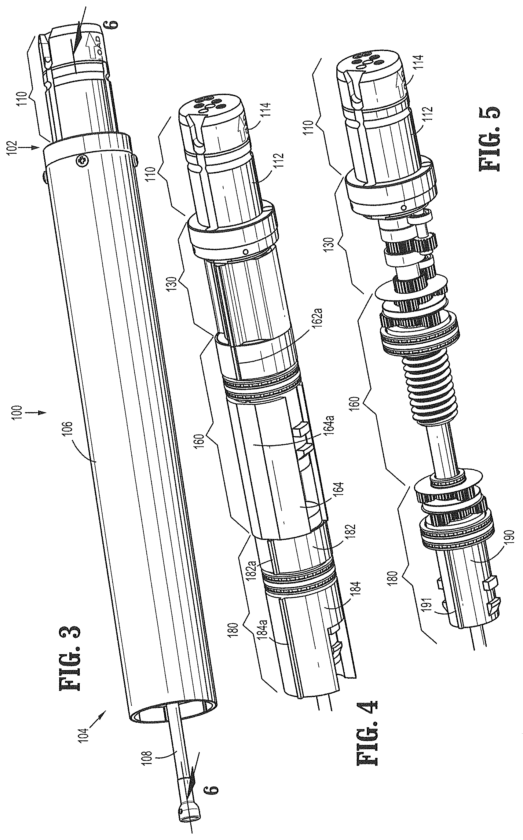
FIG. 3 is a perspective side view of the adapter assembly of FIG. 1;
FIG. 4 is a perspective side view of the adapter assembly of FIG. 3 with the outer sleeve removed;
FIG. 5 is a perspective side view of the adapter assembly of FIGS. 3 and 4 with proximal and distal housings of first and second pusher assemblies removed;
FIG. 6 is a cross-sectional side view of the adapter assembly of FIGS. 2-4 taken along line 6-6 in FIG. 3;
FIG. 7 is a cross-sectional side view of the adapter assembly of FIGS. 2-5 taken along line 7-7 in FIG. 5;
FIG. 8 is an enlarged, perspective view of a coupling assembly and a transfer assembly of the adapter assembly of FIGS. 2-7;
FIG. 9 is a perspective side view of adapter assembly of FIGS. 2-7 with the housing assemblies removed;
FIG. 10 is an enlarged view of the indicated area of detail of FIG. 9;
FIG. 11 is an enlarged view of the indicated area of detail of FIG. 6;
FIG. 12 is an enlarged view of the indicated area of detail of FIG. 7;
FIG. 13 is a perspective end view of the transfer assembly of FIG. 8;
FIG. 14 is an enlarged view of the indicated area of detail of FIG. 6;
FIG. 15 is an enlarged view of the indicated area of detail of FIG. 7;
FIG. 16 is an enlarged view of the indicated area of detail of FIG. 9;
FIG. 17 is a perspective side view of the extension assembly of FIG. 1;
FIG. 18 is a perspective side view of an inner flexible band assembly of the extension assembly of FIG. 17;
FIG. 19 is a perspective side view of an outer flexible band assembly of the extension assembly of FIG. 17;
FIG. 20 is a perspective side view of the inner and outer flexible band assemblies of FIGS. 18 and 19 and an exploded view of a frame assembly of the extension assembly of FIG. 17;
FIG. 21 is a perspective side view of the inner and outer flexible band assemblies and frame assembly of FIG. 20;
FIG. 22 is an enlarged view of the indicated area of detail of FIG. 21;
FIG. 23 is a front, perspective view of the inner and outer flexible band assemblies and frame assembly of FIG. 20;
FIG. 24 is an enlarged view of the indicated area of detail of FIG. 23;
FIG. 25 is a cross-sectional end view taken along line 25-25 of FIG. 17;
FIG. 26 is a cross-sectional end view taken along line 26-26 of FIG. 17;
FIG. 27 is an enlarged perspective side view of a distal end of the inner and outer flexible band assemblies and frame assembly of FIG. 20 including a proximal seal member and first and second distal seal members;
FIG. 28 is an exploded perspective view of the proximal seal member and first and second distal seal members of FIG. 27;
FIG. 29 is an exploded view of a trocar assembly of the extension assembly of FIG. 17;
FIG. 29A is a perspective side view of a link assembly of the extension assembly of FIG. 17;
FIG. 29B is a cross-section side view of the link assembly of FIG. 29A;
FIG. 30 is a perspective side view of the trocar assembly of FIG. 29;
FIG. 31 is a cross-sectional side view taken along line 31-31 of FIG. 30;
FIG. 32 is a cross-sectional top view taken along line 32-32 of FIG. 17;
FIG. 33 is an enlarged cross-sectional view of the distal end of the extension assembly of FIG. 17;
FIG. 34 is a perspective side view of the adapter assembly of FIG. 3 connected to the extension assembly of FIG. 17 and an end effector and an anvil assembly connected to the extension assembly;
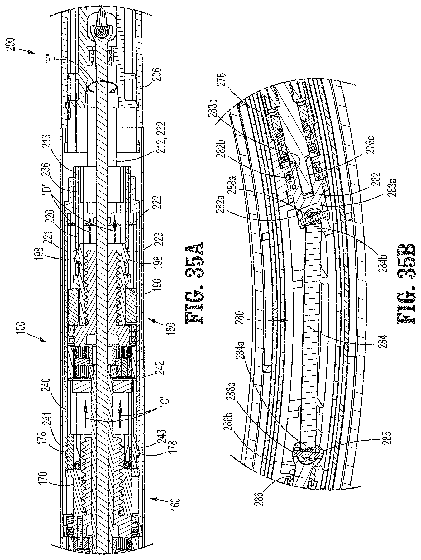
FIG. 35A is an enlarged cross-sectional top view of the indicated area of detail of FIG. 34;
FIG. 35B is an enlarged cross-sectional side view of the indicated area of detail in FIG. 34;
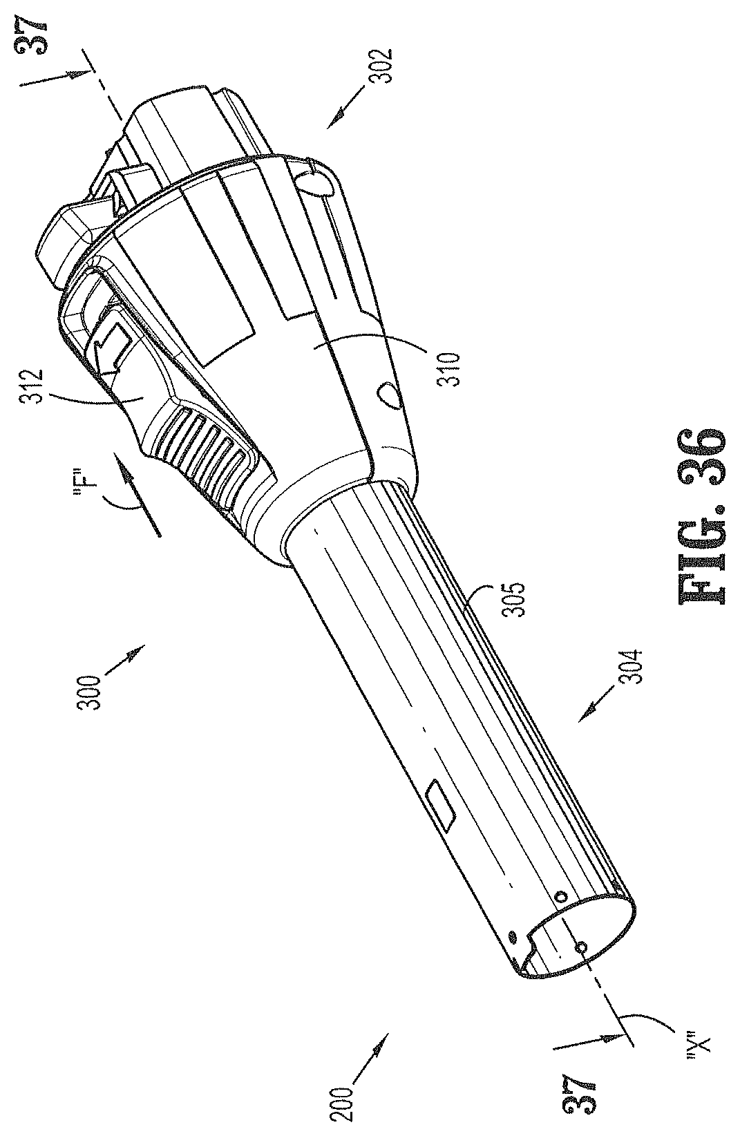
FIG. 36 is a perspective side view of an adapter assembly according to another embodiment of the present disclosure;
FIG. 37 is a cross-sectional side view taken along line 37-37 of FIG. 36;
FIG. 38 is an enlarged cross-sectional side view of the indicated area of detail of FIG. 37;
FIG. 39 is an exploded perspective view of a pusher assembly of the adapter assembly of FIG. 36;
FIG. 40 is a perspective side view of the pusher assembly of FIG. 39;
FIG. 41 is a cross-sectional side view taken along line 41-41 of FIG. 40;
FIG. 42 is a cross-sectional top view of the adapter assembly of FIG. 36 secured to the extension assembly of FIG. 17;
FIG. 43 is an enlarged cross-sectional top view of the indicated area of detail of FIG. 42, prior to full securement of the extension assembly to the adapter assembly;
FIG. 44 is an enlarged cross-sectional top view of the indicated area of detail of FIG. 42, with the extension assembly secured to the adapter assembly;
FIG. 45 is a perspective side view of the adapter assembly and extension assembly of FIG. 42, with outer sleeves removed;
FIG. 46 is a perspective side view of a pusher member in accordance with another embodiment of the present disclosure;
FIG. 47 is a cross-sectional side view taken along line 47-47 of FIG. 46; and
FIG. 48 is a perspective view, with parts separated, of the pusher member of FIGS. 46 and 47.
DETAILED DESCRIPTION OF EMBODIMENTS
Embodiments of the presently disclosed adapter assemblies and extension assemblies for surgical devices and/or handle assemblies are described in detail with reference to the drawings, in which like reference numerals designate identical or corresponding elements in each of the several views. As used herein the term "distal" refers to that portion of the adapter assembly or surgical device, or component thereof, farther from the user, while the term "proximal" refers to that portion of the adapter assembly or surgical device, or component thereof, closer to the user.
With reference to FIG. 1, an adapter assembly in accordance with an embodiment of the present disclosure, shown generally as adapter assembly 100, is configured for selective connection to a powered handheld electromechanical instrument shown, generally as surgical device 10. As illustrated in FIG. 1, the surgical device 10 is configured for selective connection with the adapter assembly 100, and, in turn, the adapter assembly 100 is configured for selective connection with an extension assembly 200. The extension assembly 200 is configured for selective connection with a tool assembly or end effector, e.g. tool assembly 30 (FIG. 34), including a loading unit, e.g. loading unit 40 (FIG. 34), and an anvil assembly, e.g., anvil assembly 50 (FIG. 34), for applying a circular array of staples (not shown) to tissue (not shown).
As illustrated in FIGS. 1 and 2, the surgical device 10 includes a handle housing 12 having a lower housing portion 14, an intermediate housing portion 16 extending from and/or supported on the lower housing portion 14, and an upper housing portion 18 extending from and/or supported on the intermediate housing portion 16. A distal half-section of the upper housing portion 18 defines a nose or connecting portion 18a configured to accept a corresponding drive coupling assembly 110 (FIG. 10) of the adapter assembly 100. For a detailed description of the structure and function of an exemplary electromechanical instrument, please refer to commonly owned U.S. Pat. Appl. Publ. No. 2012/0253329 ("the '329 application"), the contents of which is incorporated by reference herein in its entirety.
The adapter assembly 100 will now be described with reference to FIGS. 3-20. Referring initially to FIG. 3, the adapter assembly 100 includes a proximal end 102 configured for operable connection to the connecting portion 18a (FIG. 1) of the surgical device 10 (FIG. 1) and a distal end 104 configured for operable connection to the extension assembly 200 (FIG. 1).
Turning to FIGS. 3-5, from the proximal end 102 to the distal end 104 of the adapter assembly 100, the adapter assembly 100 includes a drive coupling assembly 110, a drive transfer assembly 130 operably connected to the drive coupling assembly 110, a first pusher assembly 160 operably connected to the drive transfer assembly 130, and a second pusher assembly 180 operably connected to the drive transfer assembly 130. Each of the drive transfer assembly 130 and the first and second pusher assemblies 160, 180 are operably maintained within an outer sleeve 106 (FIG. 3). As will be described in further detail below, a shaft 108 (FIG. 3) extends longitudinally through the adapter assembly 100 and is operably connected to the drive transfer assembly 130.
With reference to FIGS. 5-9, the drive coupling assembly 110 has a cylindrical profile and is configured to selectively secure the adapter assembly 100 to the surgical device 10 (FIG. 1). The drive coupling assembly 110 includes a connector housing 112 and a connector extension 114 fixedly connected to the connector housing 112 by a mounting plate 113. The connector housing 112 and the connector extension 114 operate to rotatably support a first rotatable proximal drive shaft 116, a second rotatable proximal drive shaft 118, and a third rotatable proximal drive shaft 120. The connector housing 112 and the connector extension 114 of the drive coupling assembly 110 also rotatably support the first, second, and third connector sleeves 122, 124, and 126, respectively. Each of the connector sleeves 122, 124, 126 is configured to mate with the respective first, second, and third drive connectors (not shown) of surgical device 10 (FIG. 1). Each of the connector sleeves 122, 124, 126 is further configured to mate with a proximal end 116a, 118a, 120a of the respective first, second and third proximal drive shafts 116, 118, 120.
The drive coupling assembly 110 also includes first, second and third biasing members 122a, 124a and 126a disposed distally of the respective first, second and third connector sleeves 122, 124, 126. Each of the biasing members 122a, 124a and 126a is disposed about the respective first, second, and third rotatable proximal drive shafts 122, 124 and 126 to help maintain the connector sleeves 122, 124, and 126 engaged with the distal end of the respective rotatable drive connectors (not shown) of the surgical device 10 when the adapter assembly 100 is connected to the surgical device 10. In particular, the first, second, and third biasing members 122a, 124a, and 126a function to bias the respective connector sleeves 122, 124, and 126 in a proximal direction.
For a detailed description of an exemplary drive coupling assembly, please refer to the '329 application, the contents of which were previously incorporated by reference herein.
With reference to FIGS. 9-13, the drive transfer assembly 130 has a cylindrical profile and operably connects the distal ends of the first, second, and third rotatable proximal drive shafts 116, 118, and 120 to the shaft 108, the first pusher assembly 160, and the second pusher assembly 180, respectively. The drive transfer assembly 130 includes a support plate 132 (FIGS. 11 and 12) secured to a proximal end of the connector housing 112 and a drive transfer housing 134 positioned adjacent the support plate 132. The support plate 132 and the housing 134 operate to rotatably support a first rotatable distal drive shaft 136, a second rotatable distal drive shaft 138 and a drive member 140.
The first and second rotatable distal drive shafts 136 and 138 are each operably connected to the respective first and second rotatable proximal drive shafts 116 and 118 of the drive coupling assembly 110 by a pair of gears. In particular, the distal ends of each of the first and second rotatable proximal drive shaft 116 and 118 include a geared portion 142a and 144a, respectively, which engages a proximal drive gear 142b and 144b on a proximal end of the respective first and second distal drive shafts 136 and 138. As shown, each of the respective paired geared portions and proximal drive gears 142a, 142b and 144a, 144b are the same size to provide a 1:1 gear ratio between the respective first and second rotatable proximal and distal drive shafts 116, 136 and 118, 138. In this manner, the respective first and second rotatable proximal and distal drive shafts 116, 136 and 118, 138 rotate at the same speed. However, it is envisioned that either or both of the paired geared portions and proximal drive gears may be of different sizes to alter the gear ratio between the first and second rotatable proximal and distal drive shafts 116, 136 and 118, 138.
A distal end of the third proximal drive shaft 120 of the drive coupling assembly 110 includes a geared portion 146a that engages a geared portion 146b formed on a proximal end of the drive member 140 of the drive transfer assembly 130. The size of the geared portion 146a on the third proximal drive shaft 120 and the geared portion 146b on the drive member 140 are the same size to provide a 1:1 gear ratio between the third proximal drive shaft 120 and the drive member 140. In this manner, the third proximal drive shaft 120 and the drive member 140 rotate at the same speed. However, it is envisioned that either or both of the geared portions 146a, 146b may be of different sizes to alter the gear ratio between the third proximal drive shaft 120 and the drive member 140. A distal end of the drive member 140 defines a socket 145 that receives a proximal end 108a of the shaft 108. Alternatively, the socket 145 may be configured to operably engage a proximal end 208a of a drive shaft (FIG. 17) of an extension assembly 200 (FIG. 17).
The drive transfer assembly 130 also includes a drive connector 148 (FIG. 11) operably connecting the first rotatable distal drive shaft 136 to the first pusher assembly 160 and a tubular connector 150 operably connecting the second rotatable distal drive shaft 138 to the second pusher assembly 180. In particular, a distal end of the first rotatable distal drive shaft 136 includes a geared portion 152a that engages a geared portion 152b of the drive connector 148. A distal end of the second rotatable distal drive shaft 138 includes a geared portion 154a that engages a drive gear 154b secured to a distal end of the tubular connector 150.
As shown, the geared portion 152a of the first rotatable distal drive shaft 136 is smaller than the geared portion 152b of the drive connector 148 to provide a gear ratio of greater than 1:1 between the first rotatable distal drive shaft 136 and the drive connector 148. In this manner, the drive connector 148 rotates at a slower speed than the first rotatable distal drive shaft 136. Similarly, the geared portion 154a of the second rotatable distal drive shaft 138 is smaller than the drive gear 154b on the tubular connector 150 to provide a gear ratio of greater than 1:1 between the second rotatable distal drive shaft 138 and the drive connector 148. In this manner, the tubular connector 150 rotates at a slower speed than the second rotatable distal drive shaft 138. However, it is envisioned that each of the paired geared portions 152a, 152b, and the geared portion 154a and the drive gear 154b may be the same size to provide a gear ratio of 1:1 between the respective first rotatable distal drive shaft 136 and the drive connector 148 and between the second rotatable distal drive shaft 138 and the tubular connector 150.
With particular reference to FIGS. 9-13, the first pusher assembly 160 includes proximal and distal housing sections 162, 164 (FIG. 11), a planetary gear assembly 166 operably mounted within the proximal housing section 162, a screw member 168 (FIG. 11) operably connected to the planetary gear assembly 166 and rotatably supported within the distal housing section 164, and a pusher member 170 (FIG. 11) operably connected to the screw member 168 and slidably disposed within the distal housing section 164. The proximal housing section 162 includes a pair of longitudinal flanges 162a (FIG. 4; only one shown) and the distal housing section 164 includes a pair of longitudinally flattened portions 164a. Each of the flanges 162a and the flattened portions 164a of the respective proximal and distal housing sections 162, 164 engage an inner surface of the sleeve 106 to prevent rotation of the respective proximal housing section 162 and the distal housing section 164 relative to the sleeve 106 during operation of the surgical device 10.
The planetary gear assembly 166 includes first and second planetary gear systems 166a, 166b (FIG. 10). The first planetary gear system 166a of the first pusher assembly 160 includes a central drive gear 172a mounted on a distal end of the drive connector 148 of the drive transfer assembly 130 and a plurality of planetary gears 174a rotatably mounted to a rotatable support ring 176.
Each of the planetary gears 174a engages the central drive gear 172a and a toothed inner surface 165 of the proximal housing section 162. As central drive gear 172a rotates in a first direction, i.e., clockwise, each of the planetary gears 174a rotates in a second direction, i.e., counter-clockwise. As each of the planetary gears 174a rotates in the second direction, engagement of the planetary gears 174a with the toothed inner surface 165 of the distal housing section 162 causes the rotatable support ring 176 to rotate in the first direction. Conversely, rotation of the central drive gear 172a in the second direction causes rotation of each of the planetary gears 174a in the first direction thereby causing rotation of the rotatable support ring 176 in the second direction. The configuration of the first planetary gear system 166a provides a reduction in the gear ratio. In this manner, the speed of rotation of the rotatable support ring 174 is less than the speed of rotation of the central drive gear 172a.
The second planetary gear system 166b of the first pusher assembly 160 includes a central drive gear 172b securely affixed to the rotatable support ring 176 and a plurality of planetary gears 174b rotatably mounted to a proximal end surface 168a of the screw member 168. Each of the planetary gears 174b engages the central drive gear 172b and the toothed inner surface 165 of the proximal housing section 162. As the rotatable support ring 176 of the first planetary gear system 166a rotates in the first direction thereby causing the central drive gear 172b to also rotate in the first direction, each of the planetary gears 174b rotates in the second direction. As each of the planetary gears 174b rotates in the second direction, engagement of the planetary gears 174b with the toothed inner surface 165 of the proximal housing section 162 causes the screw member 168 to rotate in the first direction. Conversely, rotation of the central drive gear 172b in the second direction causes rotation of each of the planetary gears 174b in the first direction, thereby causing the screw member 168 to rotate in the second direction. The configuration of the second planetary gear system 166b provides a reduction in the gear ratio. In this manner, the speed of rotation of the screw member 168 is less than the speed of rotation of the central drive gear 172b.
The first and second planetary gear systems 166a, 166b operate in unison to provide a reduction in the gear ratio between the first rotatable proximal drive shaft 116 and the screw member 168. In this manner, the reduction in the speed of rotation of the screw member 168 relative to the drive connector 148 is a product of the reduction provided by the first and second planetary gear systems 166a, 166b.
The screw member 168 is rotatably supported within the proximal housing portion 162 and includes a threaded distal end 168b that operably engages a threaded inner surface 170a of the pusher member 170. As the screw member 168 is rotated in the first direction, engagement of the threaded distal end 168b of the screw member 168 with the threaded inner surface 170a of the pusher member 170 causes longitudinal advancement of the pusher member 170, as indicated by arrows "A" in FIG. 12. Conversely, rotation of the screw member 168 in the second direction causes retraction of the pusher member 170.
The pusher member 170 includes a pair of tabs 178 formed on a distal end thereof for engaging the connector extensions 240, 242 (FIG. 19) of the outer flexible band assembly 230 (FIG. 19) of the extension assembly 200 (FIG. 17). Although shown as tabs 178, it is envisioned that the pusher member 170 may include any structure suitable for selectively engaging the connector extensions 240, 242 of the outer flexible band 230 of the extension assembly 200.
With particular reference now to FIGS. 14-16, the second pusher assembly 180 is substantially similar to the first pusher assembly 160, and includes proximal and distal housing sections 182, 184, a planetary gear assembly 186 operably mounted within the proximal housing section 182, a screw member 188 operably connected to the planetary gear assembly 186 and rotatably supported within the distal housing section 184, and a pusher member 190 operably connected to the screw member 188 and slidably disposed within the distal housing section 184. Each of the proximal housing section 182 and the distal housing section 184 includes a pair of longitudinal flanges 182a, 184a (FIG. 4; only one shown), respectively, engaging an inner surface of the sleeve 106 of the adapter assembly 100 to prevent rotation of the respective proximal housing section 182 and the distal housing section 184 relative to the sleeve 106 during operation of the surgical device 10.
The planetary gear assembly 186 includes first and second planetary gear systems 186a, 186b (FIG. 16). The first planetary gear system 186a of the second pusher assembly 180 includes a central drive gear 192a mounted on a distal end of the tubular connector 150 of the drive transfer assembly 130 and a plurality of planetary gears 194a rotatably mounted to a rotatable support ring 196.
Each of the planetary gears 194a engages the central drive gear 192a and a toothed inner surface 185 of the proximal housing section 182. As central drive gear 192a rotates in a first direction, i.e., clockwise, each of the planetary gears 194a rotates in a second direction, i.e., counter-clockwise. As each of the planetary gears 194a rotates in the second direction, engagement of the planetary gears 194a with toothed inner surface 185 of the distal housing section 182 causes the rotatable support ring 196 to rotate in the first direction. Conversely, rotation of the central drive gear 192a in the second direction causes rotation of each of the planetary gears 194a in the first direction thereby causing rotation of the rotatable support ring 196 in the second direction. The configuration of the first planetary gear system 186a provides a reduction in the gear ratio. In this manner, the speed of rotation of the rotatable support ring 194 is less than the speed of rotation of the central drive gear 190a.
The second planetary gear system 186b of the second pusher assembly 180 includes a central drive gear 192b securely affixed to the rotatable support ring 196 and a plurality of planetary gears 194b rotatably mounted to a proximal end surface 188a of the screw member 188. Each of the planetary gears 194b engages the central drive gear 192b and the toothed inner surface 185 of the proximal housing section 182. As the rotatable support ring 196 of the first planetary gear system 186a rotates in the first direction thereby causing the central drive gear 192b to also rotate in the first direction, each of the planetary gears 174b rotates in the second direction. As each of the planetary gears 194b rotates in the second direction, engagement of the planetary gears 194b with the toothed inner surface 185 of the proximal housing section 182 causes the screw member 188 to rotate in the first direction. Conversely, rotation of the central drive gear 192b in the second direction causes rotation of each of the planetary gears 194b in the first direction, thereby causing the screw member 198 to rotate in the second direction. The configuration of the second planetary gear system 186b provides a reduction in the gear ratio. In this manner, the speed of rotation of the screw member 188 is less than the speed of rotation of the central drive gear 182b. The first and second planetary gear systems 186a, 186b operate in unison to provide a reduction in the gear ratio between the second rotatable proximal drive shaft 118 and the screw member 188. In this manner, the reduction in the speed of rotation of the screw member 188 relative to the tubular connector 150 is a product of the reduction provided by the first and second planetary gear systems 186a, 186b.
The screw member 188 is rotatably supported within the proximal housing portion 182 and includes a threaded distal end 188b that operably engages a threaded inner surface 190a of the pusher member 190. As the screw member 188 is rotated in the first direction, engagement of the threaded distal end 188b of the screw member 188 with the threaded inner surface 190a of the pusher member 190 causes longitudinal advancement of the pusher member 190. Conversely, rotation of the screw member 188 in the second direction causes retraction of the pusher member 190. The pusher member 190 includes a pair of longitudinal flanges 191 (FIG. 5; only one shown) that engage the distal housing section 184 of the second pusher assembly 180 for preventing rotation of the pusher member 190 relative to the distal housing section 184.
The pusher member 190 includes a pair of tabs 198 formed on a distal end thereof for engaging the connector extensions 220, 224 (FIG. 18) of the inner flexible band assembly 220 (FIG. 18) of the extension assembly 200 (FIG. 17). Although shown as tabs 198, it is envisioned that the pusher member 190 may include any structure suitable for selectively engaging the connector extensions 240, 242 of the outer flexible band 230 of the extension assembly 200.
The extension assembly 200 for operably connecting the adapter assembly 100 (FIG. 3) with a circular loading unit, e.g. the loading unit 40 (FIG. 34) and an anvil assembly, e.g., the anvil assembly 50 (FIG. 34) will be described with reference now to FIGS. 17-34. In particular, a proximal end 202 of the extension assembly 200 operably connects with the distal end 104 (FIG. 3) of the adapter assembly 100 (FIG. 3) and a distal end 204 of the extension assembly 200 operably connects with the loading unit 40 and the anvil assembly 50. As shown, the extension assembly 200 provides a slight curvature between the proximal and distal ends 202, 204. In an alternative embodiment, the extension assembly 200 may be straight or may include a greater curvature. Although the extension assembly 200 will be shown and described as being used to connect the loading unit 40 and the anvil assembly 50 to the adapter assembly 100 (FIG. 3), it is envisioned that the aspects of the present disclosure may be modified for use with various loading units, anvil assemblies, and adapter assemblies. Exemplary loading units and anvil assemblies are described in commonly owned U.S. Pat. No. 8,590,763 and U.S. patent application Ser. Nos. 14/056,301 and 14/149,355, the contents of each being incorporated herein by reference in their entirety.
The extension assembly 200 includes an inner flexible band assembly 210 (FIG. 18), an outer flexible band assembly 230 (FIG. 19) slidably disposed about the inner flexible band assembly 210, a frame assembly 250 (FIG. 20) for supporting the inner and outer flexible band assemblies 210, 230, a trocar assembly 270 (FIG. 29) operably received through the inner and outer flexible band assemblies 210, 230, and a connector assembly 290 for securing the loading unit 40 (FIG. 34) to the extension assembly 200. An outer sleeve 206 (FIG. 17) is received about the frame assembly 250 and the trocar assembly 270 and the inner and outer flexible band assemblies 210, 230 are slidably received through the outer sleeve 206. As will be described in further detail below, the extension assembly 200 may include a drive shaft 208 operably connected to the trocar assembly 270 and extending through the proximal end 202 of the extension assembly 200.
With reference to FIG. 18, the inner flexible band assembly 210 includes first and second inner flexible bands 212, 214, a support ring 216, a support base 218, and first and second connection extensions 220, 222. The proximal ends 212a, 214a of the respective first and second inner flexible bands 212, 214 are laterally spaced apart and securely attached to the support ring 216. The distal ends 212b, 214b of the first and second inner flexible bands 212, 214 are laterally spaced apart and securely attached to a proximal end 218a of the support base 218. Each of the first and second inner flexible bands 212, 214 may be attached to the support ring 216 and/or the support base 218 in any suitable manner, including, for example, by press-fitting, welding, adhesives, and/or with mechanical fasteners. As will be described in further detail below, the inner flexible band assembly 210 is configured to be slidably received about the trocar assembly 270 (FIG. 28) and within the outer flexible band assembly 230 (FIG. 19) and the outer sleeve 206 (FIG. 17).
The first and second connection extensions 220, 222 of the inner flexible band assembly 210 extend proximally from the support ring 216 and operably connect the inner flexible band assembly 210 with the pusher member 190 (FIG. 15) of the second pusher assembly 180 (FIG. 15) of the adapter assembly 100 (FIG. 3). In particular, each of the first and second connection extensions 220, 222 define openings 221, 223 configured to receive tabs 198 (FIG. 15) of the pusher member 190 (FIG. 15) of the second pusher assembly 180. Receipt of the tabs 198 of the pusher member 190 within the openings 221, 223 of the respective first and second extensions 220, 222 secure the inner flexible band assembly 210 of the extension assembly 200 with the second pusher assembly 180 of the adapter assembly 100. The first and second connection extensions 220, 222 may be integrally formed with the support ring 216, or attached thereto in any suitable manner.
The support base 218 extends distally from the inner flexible bands 212, 214 and is configured to selectively connect the extension assembly 200 with the loading unit 40 (FIG. 34). Specifically, a distal end 218b of the support base 218 includes a flange 224 for operable engagement with an axially movable assembly (not shown) of the loading unit 40 (FIG. 34). In one embodiment, the flange 224 is configured for connection with a knife assembly (not shown) of the loading unit 40 (FIG. 34).
With reference now to FIG. 19, the outer flexible band assembly 230 is substantially similar to the inner flexible band assembly 210 and includes first and second flexible bands 232, 234 laterally spaced and connected on proximal ends 232a, 234a to a support ring 236 and on distal ends 232b, 234b to a proximal end 238a of a support base 238. Each of the first and second outer flexible bands 232, 234 may be attached to the support ring 236 and the support base 238 in any suitable manner, including, for example, by press-fitting, welding, adhesives, and/or with mechanical fasteners. As will be described in further detail below, the outer flexible band assembly 230 is configured to receive the trocar assembly 270 (FIG. 29) therethrough.
The first and second connection extensions 240, 242 of the outer flexible band assembly 230 extend proximally from the support ring 236 and operably connect the outer flexible band assembly 230 with the pusher member 170 (FIG. 12) of the first pusher assembly 160 (FIG. 12) of the adapter assembly 100 (FIG. 1). In particular, each of the first and second connection extensions 240, 242 define openings 241, 243 configured to receive the tabs 178 (FIG. 12) of the pusher member 170 of the first pusher assembly 180. Receipt of the tabs 178 of the pusher member 170 within the openings 241, 243 of the respective first and second extensions 240, 242 secures the outer flexible band assembly 230 of the extension assembly 200 with the first pusher assembly 180 of the adapter assembly 100. The first and second connection extensions 240, 242 may be integrally formed with the support ring 236, or attached thereto in any suitable manner.
The support base 238 extends distally from the outer flexible bands 232, 234 and is configured to selectively connect the extension assembly 200 with the loading unit 40 (FIG. 34). Specifically, a distal end 238b of the support base 238 includes a flange 244 for operable engagement with an axially movable assembly (not shown) of a loading unit (not shown). In one embodiment, the flange 244 is configured for connection with a staple pusher assembly (not shown) of the loading unit 40 (FIG. 34).
With reference now to FIGS. 20-26, the frame assembly 250 includes first and second proximal spacer members 252, 254, and first and second distal spacer members 256, 258. When secured together, the first and second proximal spacer members 252, 254 define a pair of inner longitudinal slots 253a for slidably receiving the first and second flexible bands 212, 214 (FIG. 18) of the inner flexible band assembly 210 (FIG. 18) and a pair of outer longitudinal slots 253b for slidably receiving the first and second flexible bands 232, 234 (FIG. 19) of the outer flexible band assembly 230 (FIG. 19). The first and second proximal spacer members 252, 254 further define a longitudinal passage 255 for receipt of the trocar assembly 270.
In one embodiment, and as shown, the first and second proximal spacer members 252, 254 are formed of plastic and are secured together with a snap-fit arrangement. Alternatively, the first and second proximal spacer members 252, 254 may be formed of metal or other suitable material and may be secured together in any suitable manner, including by welding, adhesives, and/or using mechanical fasteners.
The first and second distal spacer members 256, 258 define a pair of inner slots 257a for slidably receiving the first and second flexible bands 212, 214 (FIG. 18) of the inner flexible band assembly 210 (FIG. 18) and a pair of outer slots 257b for slidably receiving the first and second flexible bands 232, 234 (FIG. 19) of the outer flexibl
D00000
D00001
D00002
D00003
D00004
D00005
D00006
D00007
D00008
D00009
D00010
D00011
D00012

D00013

D00014

D00015

D00016

D00017

D00018

D00019

D00020

D00021

D00022
D00023
D00024

D00025

D00026

D00027

D00028

D00029

D00030

XML
uspto.report is an independent third-party trademark research tool that is not affiliated, endorsed, or sponsored by the United States Patent and Trademark Office (USPTO) or any other governmental organization. The information provided by uspto.report is based on publicly available data at the time of writing and is intended for informational purposes only.
While we strive to provide accurate and up-to-date information, we do not guarantee the accuracy, completeness, reliability, or suitability of the information displayed on this site. The use of this site is at your own risk. Any reliance you place on such information is therefore strictly at your own risk.
All official trademark data, including owner information, should be verified by visiting the official USPTO website at www.uspto.gov. This site is not intended to replace professional legal advice and should not be used as a substitute for consulting with a legal professional who is knowledgeable about trademark law.