Ceiling tile microphone
Graham , et al.
U.S. patent number 10,728,653 [Application Number 15/218,297] was granted by the patent office on 2020-07-28 for ceiling tile microphone. This patent grant is currently assigned to ClearOne, Inc.. The grantee listed for this patent is ClearOne, Inc.. Invention is credited to Michael Braithwaite, Derek L. Graham, David K. Lambert.


View All Diagrams
| United States Patent | 10,728,653 |
| Graham , et al. | July 28, 2020 |
Ceiling tile microphone
Abstract
This disclosure describes an apparatus and method of an embodiment of an invention that is a ceiling tile microphone. This embodiment of the apparatus includes: a beamforming microphone array that includes beamforming and acoustic echo cancellation, the plurality of microphones of the beamforming microphone array are positioned at predetermined locations, the beamforming microphone array picks up audio input signals; a ceiling tile combined with the beamforming microphone array, the ceiling tile being sized and shaped to be mountable in a drop ceiling in place of at least one of a plurality of ceiling tiles included in the drop ceiling; where the outer surface of the ceiling tile is acoustically transparent.
| Inventors: | Graham; Derek L. (South Jordan, UT), Lambert; David K. (South Jordan, UT), Braithwaite; Michael (Austin, TX) | ||||||||||
|---|---|---|---|---|---|---|---|---|---|---|---|
| Applicant: |
|
||||||||||
| Assignee: | ClearOne, Inc. (Salt Lake City,
UT) |
||||||||||
| Family ID: | 51895798 | ||||||||||
| Appl. No.: | 15/218,297 | ||||||||||
| Filed: | July 25, 2016 |
Prior Publication Data
| Document Identifier | Publication Date | |
|---|---|---|
| US 20170134850 A1 | May 11, 2017 | |
Related U.S. Patent Documents
| Application Number | Filing Date | Patent Number | Issue Date | ||
|---|---|---|---|---|---|
| 14475849 | Sep 3, 2014 | 9813806 | |||
| 14276438 | Mar 22, 2016 | 9294839 | |||
| 14191511 | Feb 27, 2014 | ||||
| 61828524 | May 29, 2013 | ||||
| 61771751 | Mar 1, 2013 | ||||
| Current U.S. Class: | 1/1 |
| Current CPC Class: | H04R 3/005 (20130101); H04R 1/08 (20130101); H04R 17/02 (20130101); H04R 1/406 (20130101); H04R 29/005 (20130101); H04R 31/006 (20130101); H04R 1/2876 (20130101); G10L 21/0232 (20130101); H04R 3/04 (20130101); G10L 2021/02082 (20130101); H04R 2430/23 (20130101); H04R 2430/21 (20130101); H04R 2201/021 (20130101); H04R 2420/07 (20130101) |
| Current International Class: | H04R 1/40 (20060101); H04R 1/08 (20060101); G10L 21/0208 (20130101); H04R 31/00 (20060101); H04R 3/04 (20060101); H04R 1/28 (20060101); H04R 17/02 (20060101); H04R 3/00 (20060101); H04R 29/00 (20060101); G10L 21/0232 (20130101) |
References Cited [Referenced By]
U.S. Patent Documents
| 4330691 | May 1982 | Gordon |
| 4365449 | December 1982 | Liautaud |
| 5008574 | April 1991 | Kitahata |
| 6332029 | December 2001 | Azima et al. |
| 6741720 | May 2004 | Myatt |
| 8229134 | July 2012 | Duraiswami et al. |
| 8286749 | October 2012 | Stewart, Jr. et al. |
| 8297402 | October 2012 | Stewart et al. |
| 8403107 | March 2013 | Stewart, Jr. et al. |
| 8479871 | July 2013 | Stewart et al. |
| 8631897 | January 2014 | Stewart, Jr. et al. |
| 8672087 | March 2014 | Stewart, Jr. et al. |
| 9565493 | February 2017 | Abraham et al. |
| 9813806 | November 2017 | Graham et al. |
| 9826211 | November 2017 | Sawa et al. |
| 10397697 | August 2019 | Lambert et al. |
| 2002/0159603 | October 2002 | Hirai et al. |
| 2003/0107478 | June 2003 | Hendricks et al. |
| 2003/0118200 | June 2003 | Beaucoup et al. |
| 2003/0185404 | October 2003 | Milsap |
| 2006/0088173 | April 2006 | Rodman et al. |
| 2008/0260175 | October 2008 | Elko et al. |
| 2009/0147967 | June 2009 | Ishibashi et al. |
| 2010/0119097 | May 2010 | Ohtsuka |
| 2010/0215189 | August 2010 | Marton |
| 2011/0007921 | January 2011 | Stewart, Jr. et al. |
| 2011/0096631 | April 2011 | Kondo et al. |
| 2011/0311085 | December 2011 | Stewart, Jr. et al. |
| 2012/0002835 | January 2012 | Stewart, Jr. et al. |
| 2012/0080260 | April 2012 | Stewart, Jr. et al. |
| 2012/0155688 | June 2012 | Wilson |
| 2012/0169826 | July 2012 | Jeong |
| 2012/0224709 | September 2012 | Keddem |
| 2012/0327115 | December 2012 | Chhetri et al. |
| 2013/0004013 | January 2013 | Stewart, Jr. et al. |
| 2013/0015014 | January 2013 | Stewart et al. |
| 2013/0016847 | January 2013 | Steiner |
| 2013/0029684 | January 2013 | Kawaguchi et al. |
| 2013/0206501 | August 2013 | Yu et al. |
| 2013/0251181 | September 2013 | Stewart, Jr. et al. |
| 2013/0264144 | October 2013 | Hudson et al. |
| 2013/0336516 | December 2013 | Stewart et al. |
| 2013/0343549 | December 2013 | Vemireddy et al. |
| 2014/0098964 | April 2014 | Rosca |
| 2014/0233778 | August 2014 | Hardiman et al. |
| 2014/0265774 | September 2014 | Stewart, Jr. et al. |
| 2014/0286518 | September 2014 | Stewart, Jr. et al. |
| 2014/0301586 | October 2014 | Stewart, Jr. et al. |
| 2014/0341392 | November 2014 | Lambert et al. |
| 2014/0357177 | December 2014 | Stewart, Jr. et al. |
| 2015/0078582 | March 2015 | Graham et al. |
| 2016/0302002 | October 2016 | Lambert et al. |
| 2018/0160224 | June 2018 | Graham et al. |
| 2019/0371353 | December 2019 | Lambert et al. |
| 2838856 | Dec 2012 | CA | |||
| 2846323 | Sep 2014 | CA | |||
| 102833664 | Dec 2012 | CN | |||
| 104080289 | Oct 2014 | CN | |||
| 102821336 | Jan 2015 | CN | |||
| 2721837 | Apr 2014 | EP | |||
| 2778310 | Sep 2014 | EP | |||
| 2007274131 | Oct 2007 | JP | |||
| 2011104501 | Sep 2011 | WO | |||
| 2012174159 | Dec 2012 | WO | |||
Other References
|
US. Appl. No. 15/062,064, "Microphone Array Beamforming", filed Dec. 31, 2013, 1-12. cited by applicant . Advanced Network Devices, "IP Speaker--IPSCM", Feb. 2011, 2. cited by applicant . Audix Microphones, "Audix Introduces Innovative Ceiling Mics", Jun. 2011, 6. cited by applicant . Clearone, Inc., "Beamforming Microphone Array", Mar. 2012, 6. cited by applicant . Clearone, Inc., "Ceiling Microphone Array Installation Manual", Jan. 9, 2012, 20. cited by applicant . CTG Audio, "Ceiling Microphone CTG CM-01", Jun. 5, 2008, 2. cited by applicant . CTG Audio, "Installation Manual", Nov. 21, 2008, 25. cited by applicant . Sasaki, et al., "A Predefined Command Recognition System Using a Ceiling Microphone Array in Noisy Housing Environments", 2008 IEEE/RSJ International Conference on Intelligent Robots and Systems, Sep. 22-26, 2008, 7. cited by applicant . Soda, et al., "Introducing Multiple Microphone Arrays for Enhancing Smart Home Voice Control", The Institute of Electronics, Information and Communication Engineers, Technical Report of IEICE., Jan. 23-25, 2013, 7. cited by applicant . District Court Litigation, "Motion by Counter Claimant ClearOne Inc. for Preliminary Injunction", Shure, Inc. v. ClearOne, Inc. 1:17-cv-03078 (N.D. III--Eastern Division), Document No. 0295, Apr. 17, 2018, 31. cited by applicant . District Court Litigation, "Shure Incorporated's Initial Non-Infringement, Unenforceability, and Invalidity Contentions related to U.S. Pat. No. 9,813,806 Pursuant to Local Patent Rule 2.3", Shure, Inc. v. ClearOne, Inc. 1:17-cv-03078 (N.D. III--Eastern Division), Document No. 0307, Apr. 23, 2018, 116. cited by applicant . IPR, "Declaration of Durand R. Begault, Ph.D., In Support of Petition for Inter Partes Review of U.S. Pat. No. 9,565,493", ClearOne, Inc. v Shure Acquisition Holdings, Inc., IPR IPR2019-00683 (PTAB), Exhibit No. 1003, Feb. 15, 2019, 139. cited by applicant . IPR, "Petition for Inter Partes Review of U.S. Pat. No. 9,565,493", ClearOne, Inc. v Shure Acquisition Holdings, Inc., IPR IPR2019-00683 (PTAB), Paper No. 1, Feb. 15, 2019, 114. cited by applicant . District Court Litigation, "Memorandum Opinion and Order for Preliminary Injunction", Shure, Inc. v. ClearOne, Inc. 1:17-cv-03078 (N.D. III--Eastern Division), Document No. 0551, Aug. 5, 2019, 65. cited by applicant . IPR, "Decision Granting Institution of Inter Partes Review", ClearOne, Inc. v Shure Acquisition Holdings, Inc., IPR IPR2019-00683 (PTAB), Paper No. 21, Aug. 16, 2019, 37. cited by applicant . District Court Litigation, "Memorandum Opinion and Order on Claim Construction", Shure, Inc. v. ClearOne, Inc. 1:17-cv-03078 (N.D. III--Eastern Division), Document No. 613, Aug. 25, 2019, 20. cited by applicant . District Court Litigation, "Clearone's Opposition to Shure's Motion to Supplement Final Invalidity Contentions As to the '186 Patent", Shure, Inc.v. ClearOne, Inc. 1:17-cv-03078 (ND. III--Eastern Division), Document No. 702, Jan. 13, 2020, 142. cited by applicant . District Court Litigation, "Memorandum in support of Shure Incorporated's Motion to Supplement Final Invalidity Contentions as to the '186 Patent", Shure, Inc.v. ClearOne, Inc. 1:17-cv-03078 (N. D. III--Eastern Division), Document No. 695, Dec. 30, 2019, 116. cited by applicant . IPR, "File History of U.S. Appl. No. 15/218,297 Part 1 of 4", ClearOne, Inc. v Shure Acquisition Holdings, Inc., IPR IPR2019-00683 (PTAB), Exhibit 2030, Mar. 13, 2020, 254. cited by applicant . IPR, "File History of U.S. Appl. No. 15/218,297 Part 2 of 4", ClearOne, Inc.v Shure Acquisition Holdings, Inc., IPR IPR2019-00683 (PTAB), Exhibit 2030, Mar. 13, 2020, 263. cited by applicant . IPR, "File History of U.S. Appl. No. 15/218,297 Part 3 of 4", ClearOne, Inc.v Shure Acquisition Holdings, Inc., IPR IPR2019-00683 (PTAB), Exhibit 2030, Mar. 13, 2020, 250. cited by applicant . IPR, "File History of U.S. Appl. No. 15/218,297 Part 4 of 4", ClearOne, Inc.v Shure Acquisition Holdings, Inc., IPR IPR2019-00683 (PTAB), Exhibit 2030, Mar. 13, 2020, 241. cited by applicant . IPR, "Patent Owner Sur Reply", ClearOne, Inc.v Shure Acquisition Holdings, Inc., IPR IPR2019-00683 (PTAB), Paper No. 58, Mar. 13, 2020, 32. cited by applicant . IPR, "Patent Owners Revised Contingent Motion to Amend", ClearOne, Inc.v Shure Acquisition Holdings, Inc., IPR IPR2019-00683 (PTAB), Paper No. 57, Mar. 13, 2020, 42. cited by applicant . IPR, "Supplemental Declaration of Dr Jeffrey S Vipperman", ClearOne, Inc.v Shure Acquisition Holdings, Inc., IPR IPR2019-00683 (PTAB), Exhibit 2029, Mar. 13, 2020, 55. cited by applicant. |
Primary Examiner: Truong; Kenny H
Attorney, Agent or Firm: Matthew J. Booth PC Booth; Matthew J.
Parent Case Text
CROSS REFERENCE TO RELATED APPLICATIONS
This application claims priority and the benefits of the earlier filed Provisional USAN 61/771,751, filed 1 Mar. 2013, which is incorporated by reference for all purposes into this specification.
This application claims priority and the benefits of the earlier filed Provisional USAN 61/828,524, filed 29 May 2013, which is incorporated by reference for all purposes into this specification.
Additionally, this application is a continuation of U.S. Ser. No. 14/191,511, filed 27 Feb. 2014, which is incorporated by reference for all purposes into this specification.
Additionally, this application is a continuation of U.S. Ser. No. 14/276,438, filed 13 May 2014, which is incorporated by reference for all purposes into this specification.
Additionally, this application is a continuation of U.S. Ser. No. 14/475,849, filed 3 Sep. 2014, which is incorporated by reference for all purposes into this specification.
Claims
We claim the following invention:
1. A ceiling tile microphone, comprising: a beamforming microphone array that includes beamforming and acoustic echo cancellation, a plurality of microphones of the beamforming microphone array are positioned at predetermined locations, the beamforming microphone array picks up audio input signals, the beamforming microphone array includes adaptive acoustic processing that automatically adjusts to a room configuration; a ceiling tile combined with the beamforming microphone array, the ceiling tile being sized and shaped to be mountable in a drop ceiling in place of at least one of a plurality of ceiling tiles included in the drop ceiling; where an outer surface of the ceiling tile is acoustically transparent.
2. The ceiling tile microphone of claim 1, where the length and width dimensions of the ceiling tile are substantially equivalent to a cell size of a grid forming the drop ceiling.
3. The ceiling tile microphone of claim 1, where the ceiling tile is sized and shaped to replace more than one of the plurality of ceiling tiles.
4. The ceiling tile microphone of claim 1, further comprising one or more external indicators coupled to the beamforming microphone array and configured to indicate the operating mode of the array.
5. The ceiling tile microphone of claim 1, where the ceiling tile comprises acoustic or vibration damping material.
6. The ceiling tile microphone of claim 1, where the beamforming microphone array includes a configurable pickup pattern for the beamforming.
7. The ceiling tile microphone of claim 1, where the beamforming microphone array includes adaptive steering technology.
8. The ceiling tile microphone of claim 1, where the beamforming microphone array includes adjustable noise cancellation.
9. A method of manufacturing a ceiling tile microphone, comprising: providing a beamforming microphone array that includes beamforming and acoustic echo cancellation, a plurality of microphones of the beamforming microphone array are positioned at predetermined locations, the beamforming microphone array picks up audio input signals, the beamforming microphone array includes adaptive acoustic processing that automatically adjusts to a room configuration; combining a ceiling tile with the beamforming microphone array, the ceiling tile being sized and shaped to be mountable in a drop ceiling in place of at least one of a plurality of ceiling tiles included in the drop ceiling; where an outer surface of the ceiling tile is acoustically transparent.
10. The method of manufacturing a ceiling tile microphone of claim 9, where the length and width dimensions of the ceiling tile are substantially equivalent to a cell size of a grid forming the drop ceiling.
11. The method of manufacturing a ceiling tile microphone of claim 9, where the ceiling tile is sized and shaped to replace more than one of the plurality of ceiling tiles.
12. The method of manufacturing a ceiling tile microphone of claim 9, further comprising one or more external indicators coupled to the beamforming microphone array and configured to indicate the operating mode of the array.
13. The method of manufacturing a ceiling tile microphone of claim 9, where the ceiling tile comprises acoustic or vibration damping material.
14. The method of manufacturing a ceiling tile microphone of claim 9, where the beamforming microphone array includes a configurable pickup pattern for the beamforming.
15. The method of manufacturing a ceiling tile microphone of claim 9, where the beamforming microphone array includes adaptive steering technology.
16. The method of manufacturing a ceiling tile microphone of claim 9, where the beamforming microphone array includes adjustable noise cancellation.
17. A method of using a ceiling tile microphone, comprising: picking up audio input signals with a beamforming microphone array that includes beamforming and acoustic echo cancellation, a plurality of microphones of the beamforming microphone array are positioned at predetermined locations, the beamforming microphone array includes adaptive acoustic processing that automatically adjusts to a room configuration; providing a ceiling tile combined with the beamforming microphone array, the ceiling tile being sized and shaped to be mountable in a drop ceiling in place of at least one of a plurality of ceiling tiles included in the drop ceiling; where an outer surface of the ceiling tile is acoustically transparent.
18. The method of claim 17, where the length and width dimensions of the ceiling tile are substantially equivalent to a cell size of a grid forming the drop ceiling.
19. The method of claim 17, where the ceiling tile is sized and shaped to replace more than one of the plurality of ceiling tiles.
20. The method of claim 17, further comprising one or more external indicators coupled to the beamforming microphone array and configured to indicate the operating mode of the array.
21. The method of claim 17, where the ceiling tile comprises acoustic or vibration damping material.
22. The method of claim 17, where the beamforming microphone array includes a configurable pickup pattern for the beamforming.
23. The method of claim 17, where the beamforming microphone array includes adaptive steering technology.
24. The method of claim 17, where the beamforming microphone array includes adjustable noise cancellation.
Description
TECHNICAL FIELD
This disclosure relates to beamforming microphone arrays. More specifically, this invention disclosure relates to beamforming microphone array systems with support for interior design elements.
BACKGROUND ART
A traditional beamforming microphone array is configured for use with a professionally installed application, such as video conferencing in a conference room. Such microphone array typically has an electro-mechanical design that requires the array to be installed or set-up as a separate device with its own mounting system in addition to other elements (e.g., lighting fixtures, decorative items and motifs, etc.) in the room. For example, a ceiling-mounted beamforming microphone array may be installed as a separate component with a suspended or "drop" ceiling using suspended ceiling tiles in the conference room. In another example, the ceiling-mounted beamforming microphone array may be installed in addition to a lighting fixture in a conference room.
Problems with the Prior Art
The traditional approach for installing a ceiling-mounted, a wall-mounted, or a table mounted beamforming microphone array results in the array being visible to people in the conference room. Once such approach is disclosed in U.S. Pat. No. 8,229,134 discussing a beamforming microphone array and a camera. However, it is not practical for a video or teleconference conference room since the color scheme, size, and geometric shape of the array might not blend well with the decor of the conference room. Also, the cost of installation of the array involves an additional cost of a ceiling-mount or a wall-mount system for the array.
Solution to Problem
Embodiments of this disclosure are in the form of a ceiling tile (with or without sound absorbing material), light fixtures, or wall panels (with or without sound absorbing materials), and acoustic wall panels.
Advantageous Effects of Invention
The commercial advantages of various embodiments of this disclosure are: smaller physical size and lower cost compared to a design based on prior art that performs beamforming through the entire range of human hearing; and the simplicity of installation such as the ceiling tile microphone embodiment.
SUMMARY OF INVENTION
This disclosure describes an apparatus and method of an embodiment of an invention that is a ceiling tile microphone. This embodiment of the apparatus includes: a beamforming microphone array that includes beamforming and acoustic echo cancellation, the plurality of microphones of the beamforming microphone array are positioned at predetermined locations, the beamforming microphone array picks up audio input signals; a ceiling tile combined with the beamforming microphone array, the ceiling tile being sized and shaped to be mountable in a drop ceiling in place of at least one of a plurality of ceiling tiles included in the drop ceiling; where the outer surface of the ceiling tile is acoustically transparent.
The above embodiment of the invention may include one or more of these additional embodiments that may be combined in any and all combinations with the above embodiment. One embodiment of the invention describes where the length and width dimensions of the ceiling tile are substantially equivalent to a cell size of a grid forming the drop ceiling. One embodiment of the invention describes where the ceiling tile is sized and shaped to replace more than one of the plurality of ceiling tiles. One embodiment of the invention describes further includes one or more external indicators coupled to the beamforming microphone array and configured to indicate the operating mode of the array microphones. One embodiment of the invention describes where the acoustic echo cancellation processing may occur in the beamforming microphone array or in a separate processing device. One embodiment of the invention describes where the ceiling tile comprises acoustic or vibration damping material. One embodiment of the invention describes where the beamforming microphone array includes a configurable pickup pattern for the beamforming. One embodiment of the invention describes where the beamforming microphone array includes adaptive steering technology. One embodiment of the invention describes where the beamforming microphone array includes adjustable noise cancellation. One embodiment of the invention describes where the beamforming microphone array includes adaptive acoustic processing that automatically adjusts to the room configuration for the best possible audio pickup. One embodiment of the invention describes how the beamforming processing may occur in the beamforming microphone array or in a separate processing device.
The present disclosure further describes an apparatus and method of an embodiment of the invention as further described in this disclosure. Other and further aspects and features of the disclosure will be evident from reading the following detailed description of the embodiments, which should illustrate, not limit, the present disclosure.
BRIEF DESCRIPTION OF DRAWINGS
To further aid in understanding the disclosure, the attached drawings help illustrate specific features of the disclosure and the following is a brief description of the attached drawings:
FIGS. 1A and 1B are schematics that illustrate environments for implementing an exemplary beamforming microphone array, according to some exemplary embodiments of the present disclosure.
FIGS. 2A to 2J illustrate usage configurations of the beamforming microphone array according to an embodiment of the present disclosure.
FIG. 3 is a schematic view that illustrates a front side of the exemplary beamforming microphone array according to an embodiment of the present disclosure.
FIG. 4A is a schematic view that illustrates a back side of the exemplary beamforming microphone array according to an embodiment of the present disclosure.
FIG. 4B is a schematic view that illustrates multiple exemplary beamforming microphone arrays connected to each other, according to an embodiment of the present disclosure.
DISCLOSURE OF EMBODIMENTS
The disclosed embodiments are intended to describe aspects of the disclosure in sufficient detail to enable those skilled in the art to practice the invention. Other embodiments may be utilized and changes may be made without departing from the scope of the disclosure. The following detailed description is not to be taken in a limiting sense, and the scope of the present invention is defined only by the included claims.
Furthermore, specific implementations shown and described are only examples and should not be construed as the only way to implement or partition the present disclosure into functional elements unless specified otherwise herein. It will be readily apparent to one of ordinary skill in the art that the various embodiments of the present disclosure may be practiced by numerous other partitioning solutions.
In the following description, elements, circuits, and functions may be shown in block diagram form in order not to obscure the present disclosure in unnecessary detail. Additionally, block definitions and partitioning of logic between various blocks is exemplary of a specific implementation. It will be readily apparent to one of ordinary skill in the art that the present disclosure may be practiced by numerous other partitioning solutions. Those of ordinary skill in the art would understand that information and signals may be represented using any of a variety of different technologies and techniques. For example, data, instructions, commands, information, signals, bits, symbols, and chips that may be referenced throughout the description may be represented by voltages, currents, electromagnetic waves, magnetic fields or particles, optical fields or particles, or any combination thereof. Some drawings may illustrate signals as a single signal for clarity of presentation and description. It will be understood by a person of ordinary skill in the art that the signal may represent a bus of signals, wherein the bus may have a variety of bit widths and the present disclosure may be implemented on any number of data signals including a single data signal.
The various illustrative logical blocks, modules, and circuits described in connection with the embodiments disclosed herein may be implemented or performed with a general purpose processor, a special purpose processor, a Digital Signal Processor (DSP), an Application Specific Integrated Circuit (ASIC), a Field Programmable Gate Array (FPGA) or other programmable logic device, discrete gate or transistor logic, discrete hardware components, or any combination thereof designed to perform the functions described herein. A general purpose processor may be a microprocessor, any conventional processor, controller, microcontroller, or state machine. A general purpose processor may be considered a special purpose processor while the general purpose processor is configured to execute instructions (e.g., software code) stored on a computer readable medium. A processor may also be implemented as a combination of computing devices, such as a combination of a DSP and a microprocessor, a plurality of microprocessors, one or more microprocessors in conjunction with a DSP core, or any other such configuration.
In addition, the disclosed embodiments may be described in terms of a process that may be depicted as a flowchart, a flow diagram, a structure diagram, or a block diagram. Although a process may describe operational acts as a sequential process, many of these acts can be performed in another sequence, in parallel, or substantially concurrently. In addition, the order of the acts may be rearranged.
Elements described herein may include multiple instances of the same element. These elements may be generically indicated by a numerical designator (e.g. 110) and specifically indicated by the numerical indicator followed by an alphabetic designator (e.g., 110A) or a numeric indicator preceded by a "dash" (e.g., 110-1). For ease of following the description, for the most part element number indicators begin with the number of the drawing on which the elements are introduced or most fully discussed. For example, where feasible elements in FIG. 3 are designated with a format of 3xx, where 3 indicates FIG. 3 and xx designates the unique element.
It should be understood that any reference to an element herein using a designation such as "first," "second," and so forth does not limit the quantity or order of those elements, unless such limitation is explicitly stated. Rather, these designations may be used herein as a convenient method of distinguishing between two or more elements or instances of an element. Thus, a reference to first and second element does not mean that only two elements may be employed or that the first element must precede the second element in some manner. In addition, unless stated otherwise, a set of elements may comprise one or more elements.
Embodiments of the present disclosure describe a beamforming microphone array combined with a wall or ceiling tile that picks up audio input signals.
Non-Limiting Definitions
In various embodiments of the present disclosure, definitions of one or more terms that will be used in the document are provided below.
A "beamforming microphone" is used in the present disclosure in the context of its broadest definition. The beamforming microphone may refer to one or more omnidirectional microphones coupled together that are used with a digital signal processing algorithm to form a directional pickup pattern that could be different from the directional pickup pattern of any individual omnidirectional microphone in the array.
A "non-beamforming microphone" is used in the present disclosure in the context of its broadest definition. The non-beamforming microphone may refer to a microphone configured to pick up audio input signals over a broad frequency range received from multiple directions.
The numerous references in the disclosure to a beamforming microphone array are intended to cover any and/or all devices capable of performing respective operations in the applicable context, regardless of whether or not the same are specifically provided.
Detailed Description of the Invention follows.
FIGS. 1A and 1B are schematics that illustrate environments for implementing an exemplary beamforming microphone array, according to some exemplary embodiments of the present disclosure. The embodiment shown in FIG. 1A illustrates a first environment 100 (e.g., audio conferencing, video conferencing, etc.) that involves interaction between multiple users located within one or more substantially enclosed areas, e.g., a room. The first environment 100 may include a first location 102 having a first set of users 104 and a second location 106 having a second set of users 108. The first set of users 104 may communicate with the second set of users 108 using a first communication device 110 and a second communication device 112 respectively over a network 114. The first communication device 110 and the second communication device 112 may be implemented as any of a variety of computing devices (e.g., a server, a desktop PC, a notebook, a workstation, a personal digital assistant (PDA), a mainframe computer, a mobile computing device, an internet appliance, etc.) and calling devices (e.g., a telephone, an internet phone, etc.). The first communication device 110 may be compatible with the second communication device 112 to exchange audio, video, or data input signals with each other or any other compatible devices.
The disclosed embodiments may involve transfer of data, e.g., audio data, over the network 114. The network 114 may include, for example, one or more of the Internet, Wide Area Networks (WANs), Local Area Networks (LANs), analog or digital wired and wireless telephone networks (e.g., a PSTN, Integrated Services Digital Network (ISDN), a cellular network, and Digital Subscriber Line (xDSL)), radio, television, cable, satellite, and/or any other delivery or tunneling mechanism for carrying data. Network 114 may include multiple networks or sub-networks, each of which may include, for example, a wired or wireless data pathway. The network 114 may include a circuit-switched voice network, a packet-switched data network, or any other network able to carry electronic communications. For example, the network 114 may include networks based on the Internet protocol (IP) or asynchronous transfer mode (ATM), and may support voice using, for example, VoIP, Voice-over-ATM, or other comparable protocols used for voice data communications. Other embodiments may involve the network 114 including a cellular telephone network configured to enable exchange of text or multimedia messages.
The first environment 100 may also include a beamforming microphone array 116 (hereinafter referred to as Array 116) interfacing between the first set of users 104 and the first communication device 110 over the network 114. The Array 116 may include multiple microphones for converting ambient sounds (such as voices or other sounds) from various sound sources (such as the first set of users 104) at the first location 102 into audio input signals. In an embodiment, the Array 116 may include a combination of beamforming microphones as previously defined (BFMs) and non-beamforming microphones (NBFMs). The BFMs may be configured to capture the audio input signals (BFM signals) within a first frequency range, and the NBMs (NBM signals) may be configured to capture the audio input signals within a second frequency range.
Another embodiment of Array 116 may include Acoustic Echo Cancellation (AEC). One skilled in the art will understand that the AEC processing may occur in the same first device that includes the beamforming microphones, or it may occur in a separate device, such as a special AEC processing device or general processing device, that is in communication with the first device. In addition, another embodiment of Array 116 includes beamforming and adaptive steering technology. Further, another embodiment of Array 116 may include adaptive acoustic processing that automatically adjusts to the room configuration for the best possible audio pickup. Additionally, another embodiment of Array 116 may include a configurable pickup pattern for the beamforming. Further, another embodiment of Array 116 may provide beamforming that includes adjustable noise cancellation. In addition, another embodiment of Array 116 may include a microphone array that includes 24 microphone elements.
Embodiments of the array 116 can further include audio acoustic characteristics that include: auto voice tracking, adjustable noise cancellation, mono and stereo, replaces traditional microphones with expanded pick-up range. Embodiments of the array 116 can include auto mixer parameters that include: Number of Open Microphones (NOM), First mic priority mode, Last mic mode, Maximum number of mics mode, Ambient level, Gate threshold adjust, Off attenuation, adjust Hold time, and Decay rate. Embodiments of the array 116 can include beamforming microphone array configurations that include: Echo cancellation on/off, Noise cancellation on/off, Filters: (All Pass, Low Pass, High Pass, Notch, PEQ), ALC on/off, Gain adjust, Mute on/off, Auto gate/manual gate.
The Array 116 may transmit the captured audio input signals to the first communication device 110 for processing and transmitting the processed, captured audio input signals to the second communication device 112. In one embodiment, the first communication device 110 may be configured to perform augmented beamforming within an intended bandpass frequency window using a combination of the BFMs and one or more NBFMs. For this, the first communication device 110 may be configured to combine NBFM signals to the BFM signals to generate an audio signal that is sent to communication device 110, discussed later in greater detail, by applying one or more of various beamforming algorithms to the signals captured from the BFMs, such as, the delay and sum algorithm, the filter and sum algorithm, etc. known in the art, related art or developed later and then combining that beamformed signal with the non-beamformed signals from the NBFMs. The frequency range processed by the beamforming microphone array may be a combination of a first frequency range corresponding to the BFMs and a second frequency range corresponding to the NBFMs, discussed below. In another embodiment, the functionality of the communication device 110 may be incorporated into Array 116.
The Array 116 may be designed to perform better than a conventional beamforming microphone array by augmenting the beamforming microphones with non-beamforming microphones that may have built-in directionality, or that may have additional noise reduction processing to reduce the amount of ambient room noise captured by the Array. In one embodiment, the first communication device 110 may configure the desired frequency range to the human hearing frequency range (i.e., 20 Hz to 20 KHz); however, one of ordinary skill in the art may predefine the frequency range based on an intended application. In some embodiments, the Array 116 in association with the first communication device 110 may be additionally configured with adaptive steering technology known in the art, related art, or developed later for better signal gain in a specific direction towards an intended sound source, e.g., at least one of the first set of users 104.
The first communication device 110 may transmit one or more augmented beamforming signals within the frequency range to the second set of users 108 at the second location 106 via the second communication device 112 over the network 114. In some embodiments, the Array 116 may be combined with the first communication device 110 to form a communication system. Such system or the first communication device 110, which is configured to perform beamforming, may be implemented in hardware or a suitable combination of hardware and software, and may include one or more software systems operating on a digital signal processing platform. The "hardware" may include a combination of discrete components, an integrated circuit, an application-specific integrated circuit, a field programmable gate array, a digital signal processor, or other suitable hardware. The "software" may include one or more objects, agents, threads, lines of code, subroutines, separate software applications, two or more lines of code or other suitable software structures operating in one or more software applications or on one or more processors.
As shown in FIG. 1B, a second exemplary environment 140 (e.g., public surveillance, song recording, etc.) may involve interaction between a user and multiple entities located at open surroundings, like a playground. The second environment 140 may include a user 150 receiving sounds from various sound sources, such as, a second person 152 or a group of persons, a television 154, an animal such as a dog 156, transportation vehicles such as a car 158, etc., present in the open surroundings via an audio reception device 160. The audio reception device 160 may be in communication with, or include, the Array 116 configured to perform beamforming on audio input signals based on the sounds received or picked up from various entities behaving as sound sources, such as those mentioned above, within the predefined bandpass frequency window. The audio reception device 160 may be a wearable device which may include, but is not limited to, a hearing aid, a hand-held baton, a body clothing, eyeglass frames, etc., which may be generating the augmented beamforming signals within the frequency range, such as the human hearing frequency range.
FIGS. 2A to 2J illustrate usage configurations of the beamforming microphone array of FIG. 1A. The Array 116 may be configured and arranged into various usage configurations, such as ceiling mounted, drop-ceiling mounted, wall mounted, etc. In a first example, as shown in FIG. 2A, the Array 116 may be configured and arranged in a ceiling mounted configuration 200, in which the Array 116 may be associated with a spanner post 202 inserted into a ceiling cover plate 204 configured to be in contact with a ceiling 206. In general, the Array 116 may be suspended from the ceiling, such that the audio input signals are received or picked up by one or more microphones in the Array 116 from above an audio source, such as one of the first set of users 104. The Array 116, the spanner post 202, and the ceiling cover plate 204 may be appropriately assembled together using various fasteners such as screws, rivets, etc. known in the art, related art, or developed later. The Array 116 may be associated with additional mounting and installation tools and parts including, but not limited to, position clamps, support rails (for sliding the Array 116 in a particular axis), array mounting plate, etc. that are well known in the art and may be understood by a person having ordinary skill in the art; and hence, these tools and parts are not discussed in detail herein.
In a second example (FIGS. 2B to 2E), the Array 116 may be combined with one or more utility devices such as lighting fixtures 210, 230, 240, 250. The Array 116 includes the microphones 212-1, 212-2, . . . , 212-n that comprise Beamforming Microphones (BFM) 212 operating in the first frequency range, and non-beamforming microphones (not shown) operating in the second frequency range. Any of the lighting fixtures 210, 230, 240, 250 may include a panel 214 being appropriately suspended from the ceiling 206 (or a drop ceiling) using hanger wires or cables such as 218-1 and 218-2 over the first set of users 104 at an appropriate height from the ground. In another approach, the panel 214 may be associated with a spanner post 202 inserted into a ceiling cover plate 204 configured to be in contact with the ceiling 206 in a manner as discussed elsewhere in this disclosure.
The panel 214 may include at least one surface such as a front surface 220 oriented in the direction of an intended entity, e.g., an object, a person, etc., or any combination thereof. The front surface 220 may be substantially flat, though may include other surface configurations such contours, corrugations, depressions, extensions, grilles, and so on, based on intended applications. One skilled in the art will appreciate that the front surface can support a variety of covers, materials, and surfaces. Such surface configurations may provide visible textures that help mask imperfections in the relative flatness or color of the panel 214. The Array 116 is in contact or coupled with the front surface 220.
The front surface 220 may be configured to aesthetically support, accommodate, embed, or facilitate a variety of permanent or replaceable lighting devices of different shapes and sizes. For example, (FIG. 2B), the front surface 220 may be coupled to multiple compact fluorescent tubes (CFTs) 222-1, 222-2, 222-3, and 222-4 (collectively, CFTs 222) disposed transverse to the length of the panel 214. In another example (FIG. 2C), the front surface 220 may include one or more slots or holes (not shown) for receiving one or more hanging lamps 232-1, 232-2, 232-3, 232-4, 232-5, and 232-6 (collectively, hanging lamps 232), which may extend substantially outward from the front surface 220.
In yet another example (FIG. 2D), the front surface 220 may include one or more recesses (not shown) for receiving one or more lighting elements such as bulbs, LEDs, etc. to form recessed lamps 242-1, 242-2, 242-3, and 242-4 (collectively, recessed lamps 242). The lighting elements are concealed within the recess such that the outer surface of the recessed lamps 242 and at least a portion of the front surface 220 are substantially in the same plane. In a further example (FIG. 2E), the panel 214 may include a variety of one or more flush mounts (not shown) known in the art, related art, or developed later. The flush mounts may receive one or more lighting elements (e.g., bulbs, LEDs, etc.) or other lighting devices, or any combination thereof to correspondingly form flush-mounted lamps 252-1, 252-2, 252-3, 252-4 (collectively, flush-mounted lamps 252), which may extend outward from the front surface 220.
Each of the lighting devices such as the CFTs 222, hanging lamps 232, the recessed lamps 242, and the flush-mounted lamps 252 may be arranged in a linear pattern, however, other suitable patterns such as diagonal, random, zigzag, etc. may be implemented based on the intended application. Other examples of lighting devices may include, but not limited to, chandeliers, spot lights, and lighting chains. The lighting devices may be based on various lighting technologies such as halogen, LED, laser, etc. known in the art, related art, and developed later.
The lighting fixtures 210, 230, 240, 250 may be combined with the Array 116 in a variety of ways. For example, the panel 214 may include a geometrical socket (not shown) having an appropriate dimension to substantially receive the Array 116 configured as a standalone unit. The Array 116 may be inserted into the geometrical socket from any side or surface of the panel 214 based on either the panel design or the geometrical socket design. In one instance, the Array 116 may be inserted into the geometrical socket from an opposing side, i.e., the back side, (not shown) of the panel 214. Once inserted, the Array 116 may have at least one surface including the BFMs 212 and the NBFMs being substantially coplanar with the front surface 220 of the panel 214. The Array 116 may be appropriately assembled together with the panel 214 using various fasteners known in the art, related art, or developed later. In another example, the Array 116 may be manufactured to be combined with the lighting fixtures 210, 230, 240, 250 and form a single unit. The Array 116 may be appropriately placed with the lighting devices to prevent "shadowing" or occlusion of audio pick-up by the BFM 212 and the NBFMs.
The panel 214 may be made of various materials or combinations of materials known in the art, related art, or developed later that are configured to bear the load of the intended number of lighting devices and the Array 116 connected to the panel 214. The lighting fixtures 210, 230, 240, 250 or the panel 214 may be further configured with provisions to guide, support, embed, or connect electrical wires and cables to one or more power supplies to supply power to the lighting devices and the Array 116. Such provisions are well known in the art and may be understood by a person having ordinary skill in the art; and hence, these provisions are not discussed in detail herein.
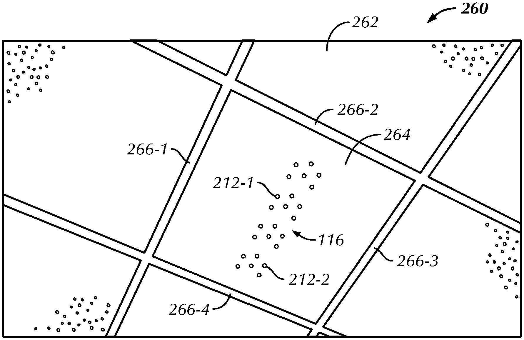
In a third example (FIGS. 2F to 2I), the Array 116 with BFMs 212 and the NBFMs may be combined to a ceiling tile for a drop ceiling mounting configuration 260. The drop ceiling 262 is a secondary ceiling suspended below the main structural ceiling, such as the ceiling 206 illustrated in FIGS. 2A-2E. The drop ceiling 262 may be created using multiple drop ceiling tiles, such as a ceiling tile 264, each arranged in a pattern based on (1) a grid design created by multiple support beams 266-1, 266-2, 266-3, 266-4 (collectively, support beams 266) connected together in a predefined manner and (2) the frame configuration of the support beams 266. Examples of the frame configurations for the support beams 266 may include, but are not limited to, standard T-shape, stepped T-shape, and reveal T-shape for receiving the ceiling tiles.
In the illustrated example (FIG. 2F), the grid design may include square gaps (not shown) between the structured arrangement of multiple support beams 266 for receiving and supporting square-shaped ceiling tiles, such as the tile 264. However, the support beams 266 may be arranged to create gaps for receiving the ceiling tiles of various sizes and shapes including, but not limited to, rectangle, triangle, rhombus, circular, and random. The ceiling tiles such as the ceiling tile 264 may be made of a variety of materials or combinations of materials including, but not limited to, metals, alloys, ceramic, fiberboards, fiberglass, plastics, polyurethane, vinyl, or any suitable acoustically neutral or transparent material known in the art, related art, or developed later. Various techniques, tools, and parts for installing the drop ceiling are well known in the art and may be understood by a person having ordinary skill in the art; and hence, these techniques, tools, and parts are not discussed in detail herein.
The ceiling tile 264 may be combined with the Array 116 in a variety of ways. In one embodiment, the ceiling tile 264 may include a geometrical socket (not shown) having an appropriate dimension to substantially receive the Array 116, which may be configured as a standalone unit. The Array 116 may be introduced into the geometrical socket from any side of the ceiling tile 264 based on the geometrical socket design. In one instance, the Array 116 may be introduced into the geometrical socket from an opposing side, i.e., the back side of the ceiling tile 264. The ceiling tile 264 may include a front side 268 (FIG. 2G) and a reverse side 270 (FIG. 2H). The front side 268 may include the Array 116 having BFMs 212 and the NBFMs arranged in a linear fashion.
The reverse side 270 of the ceiling tile 264 may be in contact with a back side of the Array 116. The reverse side 270 of the ceiling tile 264 may include hooks 272-1, 272-2, 272-3, 272-4 (collectively, hooks 272) for securing the Array 116 to the ceiling tile 264. The hooks 272 may protrude away from an intercepting edge of the back side of the Array 116 to meet the edge of the reverse side 270 of the ceiling tile 264, thereby providing a means for securing the Array 116 to the ceiling tile 264. In some embodiments, the hooks 272 may be configured to always curve inwardly towards the front side of the ceiling tile 264, unless moved manually or electromechanically in the otherwise direction, such that the inwardly curved hooks limit movement of the Array 116 to within the ceiling tile 264. In other embodiments, the hooks 272 may be a combination of multiple locking devices or parts configured to secure the Array 116 to the ceiling tile 264. Additionally, the Array 116 may be appropriately assembled together with the ceiling tile 264 using various fasteners known in the art, related art, or developed later. The Array 116 is in contact or coupled with the front surface of ceiling tile 264.
In some embodiments, the Array 116 may be combined with the ceiling tile 264 as a single unit such as a ceiling tile microphone for example. Such construction of the unit may be configured to prevent any damage to the ceiling tile 264 due to the load or weight of the Array 116. In some other embodiments, the ceiling tile 264 may be configured to include, guide, support, or connect to various components such as electrical wires, switches, and so on. In further embodiments, ceiling tile 264 may be configured to accommodate multiple arrays. In further embodiments, the Array 116 may be combined with any other tiles, such as wall tiles, in a manner discussed elsewhere in this disclosure.
The surface of the front side 268 of the ceiling tile 264 may be coplanar with the front surface of the Array 116 having the microphones of BFM 212 arranged in a linear fashion (as shown in FIG. 2G) or non-linear fashion (as shown in FIG. 2I) on the ceiling tile 264. The temporal delay in receiving audio signals using various non-linearly arranged microphones may be used to determine the direction in which a corresponding sound source is located. For example, a shipping beamformer (not shown) may be configured to include an array of twenty-four microphones in a beamforming microphone array, which may be distributed non-uniformly in a two-dimensional space. The twenty-four microphones may be selectively placed at known locations to design a set of desired audio pick-up patterns. Knowing the configuration of the microphones, such as the configuration shown in BFM 212, may allow for spatial filters being designed to create a desired "direction of look" for multiple audio beams from various sound sources.
Further, the surface of the front side 268 may be modified to include various contours, corrugations, depressions, extensions, color schemes, grilles, and designs. Such surface configurations of the front side 268 provide visible textures that help mask imperfections in the flatness or color of the ceiling tile 264. One skilled in the art will appreciate that the front surface can support a variety of covers, materials, and surfaces. The Array 116 is in contact or coupled with the front side 268.
In some embodiments, the BFMs 212, the NBFMs, or both may be embedded within contours or corrugations, depressions of the ceiling tile 264 or that of the panel 214 to disguise the Array 116 as a standard ceiling tile or a standard panel respectively. In some other embodiments, the BFMs 212 may be implemented as micro electromechanical systems (MEMS) microphones.
In a fourth example (FIG. 2J), the Array 116 may be configured and arranged to a wall mounting configuration (vertical configuration), in which the Array 116 may be embedded in a wall 280. The wall 280 may include an inner surface 282 and an outer surface 284. The Array 116 is in contact or coupled with the outer surface 284. The inner surface 282 may include a frame 286 to support various devices such as a display device 288, a camera 290, speakers 292-1, 292-2 (collectively 292), and the Array 116 being mounted on the frame 286. The frame 286 may include a predetermined arrangement of multiple wall panels 294-1, 294-2, . . . , 294-n (collectively, 294). Alternatively, the frame 286 may include a single wall panel. The wall panels 294 may facilitate such mounting of devices using a variety of fasteners such as nails, screws, and rivets, known in the art, related art, or developed later. The wall panels 294 may be made of a variety of materials, e.g., wood, metal, plastic, etc. including other suitable materials known in the art, related art, or developed later.
The multiple wall panels 294 may have a predetermined spacing 296 between them based on the intended installation or mounting of the devices. In some embodiments, the spacing 296 may be filled with various acoustic or vibration damping materials known in the art, related art, or developed later including mass-loaded vinyl polymers, clear vinyl polymers, K-Foam, and convoluted foam, and other suitable materials known in the art, related art, and developed later. These damping materials may be filled in the form of sprays, sheets, dust, shavings, including others known in the art, related art, or developed later. Such acoustic wall treatment using sound or vibration damping materials may reduce the amount of reverberation in the room, such as the first location 102 of FIG. 1A, and lead to better-sounding audio transmitted to far-end room occupants. Additionally, these materials may support an acoustic echo canceller to provide a full duplex experience by reducing the reverberation time for sounds.
In one embodiment, the outer surface 284 may be an acoustically transparent wall covering which can be made of a variety of materials known in the art, related art, or developed later that are configured to provide no or minimal resistance to sound. In one embodiment, the Array 116 and the speakers 292 may be concealed by the outer surface 284 such that the BFMs 212 and the speakers 292 may be in direct communication with the outer surface 284. One advantage of concealing the speakers may be to improve the room aesthetics.
The materials for the outer surface 284 may include materials that are acoustically transparent to the audio frequencies within the frequency range transmitted by the beamformer, but optically opaque so that room occupants, such as the first set of users 104 of FIG. 1A, may be unable to substantially notice the devices that may be mounted behind the outer surface 284. In some embodiments, the outer surface 284 may include suitable wall papers, wall tiles, etc. that can be configured to have various contours, corrugations, depressions, extensions, color schemes, etc. to blend with the decor of the room, such as the first location 102 of FIG. 1A. One skilled in the art will appreciate that the front surface can support a variety of covers, materials, and surfaces.
The combination of wall panels 294 and the outer surface 284 may provide opportunities for third party manufacturers to develop various interior design accessories such as artwork printed on acoustically transparent material with a hidden Array 116. Further, since the Array 116 may be configured for being combined with various room elements such as lighting fixtures 210, 230, 240, 250, ceiling tiles 264, and wall panels 294, a separate cost of installing the Array 116 in addition to the room elements may be significantly reduced, or completely eliminated. Additionally, the Array 116 may blend in with the room decor, thereby being substantially invisible to the naked eye.
FIG. 3 is a schematic view that illustrates a first side 300 of the exemplary beamforming microphone array according to the first embodiment of the present disclosure. At the first side 300, the Array 116 may include BFMs and NBFMs (not shown). The microphones 302-1, 302-2, 302-3, 302-n that form the Beamforming Microphone Array 302 may be arranged in a specific pattern that facilitates maximum directional coverage of various sound sources in the ambient surrounding. In an embodiment, the Array 116 may include twenty-four microphones of BFM 302 operating in a frequency range 150 Hz to 16 KHz. The Array 302 may operate in such a fashion that it offers a narrow beamwidth of a main lobe on a polar plot in the direction of a particular sound source and improve directionality or gain in that direction. The spacing between each pair of microphones of the Array 302 may be less than half of the shortest wavelength of sound intended to be spatially filtered. Above this spacing, the directionality of the Array 302 would be reduced for the previously described shortest wavelength of sound and large side lobes would begin to appear in the energy pattern on the polar plot in the direction of the sound source. The side lobes indicate alternative directions from which the Array 302 may pick-up noise, thereby reducing the directionality of the Array 302 in the direction of the sound source.
The Array 302 may be configured to pick up and convert the received sounds into audio input signals within the operating frequency range of the Array 302. Beamforming may be used to point one or more beams of the Array 302 towards a particular sound source to reduce interference and improve the quality of the received or picked up audio input signals. The Array 116 may optionally include a user interface having various elements (e.g., joystick, button pad, group of keyboard arrow keys, a digitizer screen, a touchscreen, and/or similar or equivalent controls) configured to control the operation of the Array 116 based on a user input. In some embodiments, the user interface may include buttons 304-1 and 304-2 (collectively, buttons 304), which upon being activated manually or wirelessly may adjust the operation of the BFMs 302 and the NBFMs. For example, the buttons 304-1 and 304-2 may be pressed manually to mute the BFMs 302 and the NBFMs, respectively. The elements such as the buttons 304 may be represented in different shapes or sizes and may be placed at an accessible place on the Array 116. For example, as shown, the buttons 304 may be circular in shape and positioned at opposite ends of the linear Array 116 on the first side 300.
Some embodiments of the user interface may include different numeric indicators, alphanumeric indicators, or non-alphanumeric indicators, such as different colors, different color luminance, different patterns, different textures, different graphical objects, etc. to indicate different aspects of the Array 116. In one embodiment, the buttons 304-1 and 304-2 may be colored red to indicate that the respective BFMs 302 and the NBFMs are muted.
FIG. 4A is a schematic view that illustrates a second side 400 of the beamforming microphone array of the present disclosure. At the second side 400, the Array 116 may include a link-in expansion bus (E-bus) connection 402, a link-out E-bus connection 404, a USB input port 406, a power-over-Ethernet (POE) connector 408, retention clips 410-1, 410-2, 410-3, 410-4 (collectively, retention clips 410), and a device selector 412. In one embodiment, the Array 116 may be connected to the first communication device 110 through a suitable cable, such as CAT5-24AWG solid conductor RJ45 cable, via the link-in E-bus connection 402. The link-out E-bus connection 404 may be used to connect the Array 116 using the cable to another array. The E-bus may be connected to the link-out connection 404 of the Array 116 and the link-in connection 402 of another array. In a similar manner, multiple arrays may be connected together using multiple cables for connecting each pair of the arrays. In an exemplary embodiment, as shown in FIG. 4B, the Array 116 may be connected to a first auxiliary array 414-1 and a second auxiliary array 414-2 in a daisy chain arrangement. The Array 116 may be connected to the first auxiliary array 414-1 using a first cable 416-1, and the first auxiliary array 414-1 may be connected to the second auxiliary array 414-2 using a second cable 416-2. The number of arrays being connected to each other (such as, to perform an intended operation with desired performance) may depend on processing capability and compatibility of a communication device, such as the first communication device 110, associated with at least one of the connected arrays.
Further, the first communication device 110 may be updated with appropriate firmware to configure the multiple arrays connected to each other or each of the arrays being separately connected to the first communication device 110. The USB input support port 406 may be configured to receive audio signals from any compatible device using a suitable USB cable.
The Array 116 may be powered through a standard Power over Ethernet (POE) switch or through an external POE power supply. An appropriate AC cord may be used to connect the POE power supply to the AC power. The POE cable may be plugged into the LAN+DC connection on the power supply and connected to the POE connector 408 on the Array 116. After the POE cables and the E-bus(s) are plugged to the Array 116, they may be secured under the cable retention clips 410.
The device selector 412 may be configured to interface a communicating array, such as the Array 116, to the first communication device 110. For example, the device selector 412 may assign a unique identity (ID) to each of the communicating arrays, such that the ID may be used by the first communication device 110 to interact with or control the corresponding array. The device selector 412 may be modeled in various formats. Examples of these formats include, but are not limited to, an interactive user interface, a rotary switch, etc. In some embodiments, each assigned ID may be represented as any of the indicators such as those mentioned above for communicating to the first communication device or for displaying at the arrays. For example, each ID may be represented as hexadecimal numbers ranging from `0` to `F`.
While the present disclosure has been described herein with respect to certain illustrated and described embodiments, those of ordinary skill in the art will recognize and appreciate that the present invention is not so limited. Rather, many additions, deletions, and modifications to the illustrated and described embodiments may be made without departing from the scope of the invention as hereinafter claimed along with their legal equivalents. In addition, features from one embodiment may be combined with features of another embodiment while still being encompassed within the scope of the invention as contemplated by the inventor. The disclosure of the present invention is exemplary only, with the true scope of the present invention being determined by the included claims.
* * * * *
D00000
D00001
D00002
D00003
D00004
D00005
D00006
D00007
D00008
D00009
D00010
D00011
XML
uspto.report is an independent third-party trademark research tool that is not affiliated, endorsed, or sponsored by the United States Patent and Trademark Office (USPTO) or any other governmental organization. The information provided by uspto.report is based on publicly available data at the time of writing and is intended for informational purposes only.
While we strive to provide accurate and up-to-date information, we do not guarantee the accuracy, completeness, reliability, or suitability of the information displayed on this site. The use of this site is at your own risk. Any reliance you place on such information is therefore strictly at your own risk.
All official trademark data, including owner information, should be verified by visiting the official USPTO website at www.uspto.gov. This site is not intended to replace professional legal advice and should not be used as a substitute for consulting with a legal professional who is knowledgeable about trademark law.