Method and apparatus for shelf feature and object placement detection from shelf images
Phan , et al.
U.S. patent number 10,726,273 [Application Number 15/583,740] was granted by the patent office on 2020-07-28 for method and apparatus for shelf feature and object placement detection from shelf images. This patent grant is currently assigned to Symbol Technologies, LLC. The grantee listed for this patent is SYMBOL TECHNOLOGIES, LLC. Invention is credited to Bo Fu, Raymond Phan, Richard Jeffrey Rzeszutek, Yan Zhang.


View All Diagrams
| United States Patent | 10,726,273 |
| Phan , et al. | July 28, 2020 |
Method and apparatus for shelf feature and object placement detection from shelf images
Abstract
A method of detecting a back of a shelf for supporting objects includes: obtaining an image depicting a shelf having a shelf edge and a support surface extending from the shelf edge to a shelf back; decomposing the image into a plurality of patches; for each patch: generating a feature descriptor; based on the feature descriptor, assigning one of a shelf back classification and a non-shelf back classification to the patch; generating a mask corresponding to the image, the mask containing an indication of the classification assigned to each of the patches; and presenting the mask.
| Inventors: | Phan; Raymond (Mississauga, CA), Zhang; Yan (Buffalo Grove, IL), Rzeszutek; Richard Jeffrey (Toronto, CA), Fu; Bo (Wheeling, IL) | ||||||||||
|---|---|---|---|---|---|---|---|---|---|---|---|
| Applicant: |
|
||||||||||
| Assignee: | Symbol Technologies, LLC
(Holtsville, NY) |
||||||||||
| Family ID: | 63915676 | ||||||||||
| Appl. No.: | 15/583,740 | ||||||||||
| Filed: | May 1, 2017 |
Prior Publication Data
| Document Identifier | Publication Date | |
|---|---|---|
| US 20180315173 A1 | Nov 1, 2018 | |
| Current U.S. Class: | 1/1 |
| Current CPC Class: | G06K 9/00771 (20130101); G06K 9/4642 (20130101) |
| Current International Class: | G06K 9/46 (20060101); G06K 9/66 (20060101); G06K 9/00 (20060101) |
References Cited [Referenced By]
U.S. Patent Documents
| 5209712 | May 1993 | Ferri |
| 5214615 | May 1993 | Bauer |
| 5408322 | April 1995 | Hsu et al. |
| 5414268 | May 1995 | McGee |
| 5534762 | July 1996 | Kim |
| 5566280 | October 1996 | Fukui et al. |
| 5953055 | September 1999 | Huang et al. |
| 5988862 | November 1999 | Kacyra et al. |
| 6026376 | February 2000 | Kenney |
| 6034379 | March 2000 | Bunte et al. |
| 6075905 | June 2000 | Herman et al. |
| 6115114 | September 2000 | Berg et al. |
| 6141293 | October 2000 | Amorai-Moriya et al. |
| 6304855 | October 2001 | Burke |
| 6442507 | August 2002 | Skidmore et al. |
| 6549825 | April 2003 | Kurata |
| 6580441 | June 2003 | Schileru-Key |
| 6711293 | March 2004 | Lowe |
| 6721769 | April 2004 | Rappaport et al. |
| 6836567 | December 2004 | Silver et al. |
| 6995762 | February 2006 | Pavlidis et al. |
| 7090135 | August 2006 | Patel |
| 7137207 | November 2006 | Armstrong et al. |
| 7245558 | July 2007 | Willins et al. |
| 7248754 | July 2007 | Cato |
| 7277187 | October 2007 | Smith et al. |
| 7373722 | May 2008 | Cooper et al. |
| 7474389 | January 2009 | Greenberg et al. |
| 7487595 | February 2009 | Armstrong et al. |
| 7493336 | February 2009 | Noonan |
| 7508794 | March 2009 | Feather et al. |
| 7527205 | May 2009 | Zhu et al. |
| 7605817 | October 2009 | Zhang et al. |
| 7647752 | January 2010 | Magnell |
| 7693757 | April 2010 | Zimmerman |
| 7726575 | June 2010 | Wang et al. |
| 7751928 | July 2010 | Antony et al. |
| 7783383 | August 2010 | Eliuk et al. |
| 7839531 | November 2010 | Sugiyama |
| 7845560 | December 2010 | Emanuel et al. |
| 7885865 | February 2011 | Benson et al. |
| 7925114 | April 2011 | Mai et al. |
| 7957998 | June 2011 | Riley et al. |
| 7996179 | August 2011 | Lee et al. |
| 8009864 | August 2011 | Linaker et al. |
| 8049621 | November 2011 | Egan |
| 8091782 | January 2012 | Cato et al. |
| 8094902 | January 2012 | Crandall et al. |
| 8094937 | January 2012 | Teoh et al. |
| 8132728 | March 2012 | Dwinell et al. |
| 8134717 | March 2012 | Pangrazio et al. |
| 8189855 | May 2012 | Opalach et al. |
| 8199977 | June 2012 | Krishnaswamy et al. |
| 8207964 | June 2012 | Meadow et al. |
| 8233055 | July 2012 | Matsunaga et al. |
| 8265895 | September 2012 | Willins et al. |
| 8277396 | October 2012 | Scott et al. |
| 8284988 | October 2012 | Sones et al. |
| 8423431 | April 2013 | Rouaix et al. |
| 8429004 | April 2013 | Hamilton et al. |
| 8463079 | June 2013 | Ackley et al. |
| 8479996 | July 2013 | Barkan et al. |
| 8520067 | August 2013 | Ersue |
| 8542252 | September 2013 | Perez et al. |
| 8599303 | December 2013 | Stettner |
| 8630924 | January 2014 | Groenevelt et al. |
| 8660338 | February 2014 | Ma et al. |
| 8743176 | June 2014 | Stettner et al. |
| 8757479 | June 2014 | Clark et al. |
| 8812226 | August 2014 | Zeng |
| 8923893 | December 2014 | Austin et al. |
| 8939369 | January 2015 | Olmstead et al. |
| 8954188 | February 2015 | Sullivan et al. |
| 8958911 | February 2015 | Wong et al. |
| 8971637 | March 2015 | Rivard |
| 8989342 | March 2015 | Liesenfelt et al. |
| 9007601 | April 2015 | Steffey et al. |
| 9037287 | May 2015 | Grauberger et al. |
| 9064394 | June 2015 | Trundle |
| 9070285 | June 2015 | Ramu et al. |
| 9129277 | September 2015 | MacIntosh |
| 9135491 | September 2015 | Morandi et al. |
| 9159047 | October 2015 | Winkel |
| 9171442 | October 2015 | Clements |
| 9247211 | January 2016 | Zhang et al. |
| 9329269 | May 2016 | Zeng |
| 9349076 | May 2016 | Liu et al. |
| 9367831 | June 2016 | Besehanic |
| 9380222 | June 2016 | Clayton et al. |
| 9396554 | July 2016 | Williams et al. |
| 9400170 | July 2016 | Steffey |
| 9424482 | August 2016 | Patel et al. |
| 9517767 | December 2016 | Kentley et al. |
| 9542746 | January 2017 | Wu et al. |
| 9549125 | January 2017 | Goyal et al. |
| 9562971 | February 2017 | Shenkar et al. |
| 9565400 | February 2017 | Curlander et al. |
| 9600731 | March 2017 | Yasunaga et al. |
| 9600892 | March 2017 | Patel et al. |
| 9639935 | May 2017 | Douady-Pleven et al. |
| 9697429 | July 2017 | Patel et al. |
| 9766074 | September 2017 | Roumeliotis et al. |
| 9778388 | October 2017 | Connor |
| 9791862 | October 2017 | Connor |
| 9805240 | October 2017 | Zheng et al. |
| 9811754 | November 2017 | Schwartz |
| 9827683 | November 2017 | Hance et al. |
| 9880009 | January 2018 | Bell |
| 9928708 | March 2018 | Lin et al. |
| 9980009 | May 2018 | Jiang et al. |
| 9994339 | June 2018 | Colson et al. |
| 10019803 | July 2018 | Venable et al. |
| 10111646 | October 2018 | Nycz et al. |
| 10127438 | November 2018 | Fisher |
| 10197400 | February 2019 | Jesudason et al. |
| 10210603 | February 2019 | Venable et al. |
| 10229386 | March 2019 | Thomas |
| 10248653 | April 2019 | Blassin et al. |
| 10265871 | April 2019 | Hance et al. |
| 10289990 | May 2019 | Rizzolo et al. |
| 10336543 | July 2019 | Sills et al. |
| 10349031 | July 2019 | Deluca |
| 10352689 | July 2019 | Brown et al. |
| 10394244 | August 2019 | Song et al. |
| 2001/0041948 | November 2001 | Ross et al. |
| 2002/0006231 | January 2002 | Jayant et al. |
| 2002/0097439 | July 2002 | Braica |
| 2002/0158453 | October 2002 | Levine |
| 2002/0164236 | November 2002 | Fukuhara et al. |
| 2003/0003925 | January 2003 | Suzuki |
| 2003/0174891 | September 2003 | Wenzel et al. |
| 2004/0021313 | February 2004 | Gardner et al. |
| 2004/0131278 | July 2004 | Imagawa et al. |
| 2004/0240754 | December 2004 | Smith et al. |
| 2005/0016004 | January 2005 | Armstrong et al. |
| 2005/0114059 | May 2005 | Chang et al. |
| 2005/0213082 | September 2005 | DiBernardo et al. |
| 2005/0213109 | September 2005 | Schell et al. |
| 2006/0032915 | February 2006 | Schwartz |
| 2006/0045325 | March 2006 | Zavadsky et al. |
| 2006/0106742 | May 2006 | Bochicchio et al. |
| 2006/0285486 | December 2006 | Roberts et al. |
| 2007/0036398 | February 2007 | Chen |
| 2007/0074410 | April 2007 | Armstrong et al. |
| 2007/0272732 | November 2007 | Hindmon |
| 2008/0002866 | January 2008 | Fujiwara |
| 2008/0025565 | January 2008 | Zhang et al. |
| 2008/0027591 | January 2008 | Lenser et al. |
| 2008/0077511 | March 2008 | Zimmerman |
| 2008/0159634 | July 2008 | Sharma |
| 2008/0164310 | July 2008 | Dupuy |
| 2008/0175513 | July 2008 | Lai et al. |
| 2008/0181529 | July 2008 | Michel et al. |
| 2008/0238919 | October 2008 | Pack |
| 2008/0294487 | November 2008 | Nasser |
| 2009/0009123 | January 2009 | Skaff |
| 2009/0024353 | January 2009 | Lee et al. |
| 2009/0057411 | March 2009 | Madej et al. |
| 2009/0059270 | March 2009 | Opalach et al. |
| 2009/0060349 | March 2009 | Linaker et al. |
| 2009/0063306 | March 2009 | Fano et al. |
| 2009/0063307 | March 2009 | Groenovelt et al. |
| 2009/0074303 | March 2009 | Filimonova et al. |
| 2009/0088975 | April 2009 | Sato et al. |
| 2009/0103773 | April 2009 | Wheeler et al. |
| 2009/0125350 | May 2009 | Lessing et al. |
| 2009/0125535 | May 2009 | Basso et al. |
| 2009/0152391 | June 2009 | McWhirk |
| 2009/0160975 | June 2009 | Kwan |
| 2009/0192921 | July 2009 | Hicks |
| 2009/0206161 | August 2009 | Olmstead |
| 2009/0236155 | September 2009 | Skaff |
| 2009/0252437 | October 2009 | Li et al. |
| 2009/0323121 | December 2009 | Valkenburg et al. |
| 2010/0026804 | February 2010 | Tanizaki et al. |
| 2010/0070365 | March 2010 | Siotia et al. |
| 2010/0082194 | April 2010 | Yabushita et al. |
| 2010/0091094 | April 2010 | Sekowski |
| 2010/0118116 | May 2010 | Tomasz et al. |
| 2010/0131234 | May 2010 | Stewart et al. |
| 2010/0141806 | June 2010 | Uemura et al. |
| 2010/0171826 | July 2010 | Hamilton et al. |
| 2010/0208039 | August 2010 | Setettner |
| 2010/0214873 | August 2010 | Somasundaram et al. |
| 2010/0241289 | September 2010 | Sandberg |
| 2010/0295850 | November 2010 | Katz et al. |
| 2010/0315412 | December 2010 | Sinha et al. |
| 2010/0326939 | December 2010 | Clark et al. |
| 2011/0047636 | February 2011 | Stachon et al. |
| 2011/0052043 | March 2011 | Hyung et al. |
| 2011/0093306 | April 2011 | Nielsen et al. |
| 2011/0137527 | June 2011 | Simon et al. |
| 2011/0168774 | July 2011 | Magal |
| 2011/0172875 | July 2011 | Gibbs |
| 2011/0216063 | September 2011 | Hayes |
| 2011/0242286 | October 2011 | Pace et al. |
| 2011/0254840 | October 2011 | Halstead |
| 2011/0286007 | November 2011 | Pangrazio et al. |
| 2011/0288816 | November 2011 | Thierman |
| 2011/0310088 | December 2011 | Adabala et al. |
| 2012/0019393 | January 2012 | Wolinsky et al. |
| 2012/0022913 | January 2012 | Volkmann et al. |
| 2012/0069051 | March 2012 | Hagbi et al. |
| 2012/0075342 | March 2012 | Choubassi et al. |
| 2012/0133639 | May 2012 | Kopf et al. |
| 2012/0307108 | June 2012 | Forutanpour |
| 2012/0169530 | July 2012 | Padmanabhan et al. |
| 2012/0179621 | July 2012 | Moir et al. |
| 2012/0185112 | July 2012 | Sung et al. |
| 2012/0194644 | August 2012 | Newcombe et al. |
| 2012/0197464 | August 2012 | Wang et al. |
| 2012/0201466 | August 2012 | Funayama et al. |
| 2012/0209553 | August 2012 | Doytchinov et al. |
| 2012/0236119 | September 2012 | Rhee et al. |
| 2012/0249802 | October 2012 | Taylor |
| 2012/0250978 | October 2012 | Taylor |
| 2012/0269383 | October 2012 | Bobbitt et al. |
| 2012/0287249 | November 2012 | Choo et al. |
| 2012/0323620 | December 2012 | Hofman |
| 2013/0030700 | January 2013 | Miller et al. |
| 2013/0119138 | May 2013 | Winkel |
| 2013/0132913 | May 2013 | Fu et al. |
| 2013/0134178 | May 2013 | Lu |
| 2013/0138246 | May 2013 | Gutmann et al. |
| 2013/0142421 | June 2013 | Silver et al. |
| 2013/0144565 | June 2013 | Miller |
| 2013/0154802 | June 2013 | O'Haire et al. |
| 2013/0156292 | June 2013 | Chang et al. |
| 2013/0162806 | June 2013 | Ding et al. |
| 2013/0176398 | July 2013 | Bonner et al. |
| 2013/0178227 | July 2013 | Vartanian et al. |
| 2013/0182114 | July 2013 | Zhang et al. |
| 2013/0226344 | August 2013 | Wong et al. |
| 2013/0228620 | September 2013 | Ahem et al. |
| 2013/0235165 | September 2013 | Gharib et al. |
| 2013/0236089 | September 2013 | Litvak et al. |
| 2013/0278631 | October 2013 | Border et al. |
| 2013/0299306 | November 2013 | Jiang et al. |
| 2013/0299313 | November 2013 | Baek, IV et al. |
| 2013/0300729 | November 2013 | Grimaud |
| 2013/0303193 | November 2013 | Dharwada et al. |
| 2013/0321418 | December 2013 | Kirk |
| 2013/0329013 | December 2013 | Metois et al. |
| 2013/0341400 | December 2013 | Lancaster-Larocque |
| 2014/0002597 | January 2014 | Taguchi et al. |
| 2014/0003655 | January 2014 | Gopalakrishnan |
| 2014/0003727 | January 2014 | Lortz et al. |
| 2014/0016832 | January 2014 | Kong |
| 2014/0019311 | January 2014 | Tanaka |
| 2014/0025201 | January 2014 | Ryu et al. |
| 2014/0028837 | January 2014 | Gao et al. |
| 2014/0047342 | February 2014 | Breternitz et al. |
| 2014/0049616 | February 2014 | Stettner |
| 2014/0052555 | February 2014 | MacIntosh |
| 2014/0086483 | March 2014 | Zhang et al. |
| 2014/0098094 | April 2014 | Neumann et al. |
| 2014/0100813 | April 2014 | Shaowering |
| 2014/0104413 | April 2014 | McCloskey et al. |
| 2014/0156133 | June 2014 | Cullinane et al. |
| 2014/0192050 | July 2014 | Qiu et al. |
| 2014/0195374 | July 2014 | Bassemir et al. |
| 2014/0214547 | July 2014 | Signorelli et al. |
| 2014/0267614 | September 2014 | Ding et al. |
| 2014/0267688 | September 2014 | Aich et al. |
| 2014/0277691 | September 2014 | Jacobus et al. |
| 2014/0277692 | September 2014 | Buzan et al. |
| 2014/0300637 | October 2014 | Fan et al. |
| 2014/0344401 | November 2014 | Varney et al. |
| 2014/0351073 | November 2014 | Murphy et al. |
| 2014/0369607 | December 2014 | Patel et al. |
| 2015/0015602 | January 2015 | Beaudoin |
| 2015/0019391 | January 2015 | Kumar |
| 2015/0029339 | January 2015 | Kobres et al. |
| 2015/0039458 | February 2015 | Reid |
| 2015/0088618 | March 2015 | Basir et al. |
| 2015/0088703 | March 2015 | Yan |
| 2015/0092066 | April 2015 | Geiss et al. |
| 2015/0106403 | April 2015 | Haverinen et al. |
| 2015/0117788 | April 2015 | Patel et al. |
| 2015/0139010 | May 2015 | Jeong et al. |
| 2015/0154467 | June 2015 | Feng et al. |
| 2015/0161793 | June 2015 | Takahashi |
| 2015/0170256 | June 2015 | Pettyjohn et al. |
| 2015/0181198 | June 2015 | Baele et al. |
| 2015/0245358 | August 2015 | Schmidt |
| 2015/0262116 | September 2015 | Katircioglu |
| 2015/0279035 | October 2015 | Wolski et al. |
| 2015/0298317 | October 2015 | Wang et al. |
| 2015/0352721 | December 2015 | Wicks et al. |
| 2015/0363625 | December 2015 | Wu et al. |
| 2015/0363758 | December 2015 | Wu et al. |
| 2015/0379704 | December 2015 | Chandrasekar et al. |
| 2016/0026253 | January 2016 | Bradski et al. |
| 2016/0044862 | February 2016 | Kocer |
| 2016/0061591 | March 2016 | Pangrazio et al. |
| 2016/0070981 | March 2016 | Sasaki et al. |
| 2016/0092943 | March 2016 | Vigier et al. |
| 2016/0012588 | April 2016 | Taguchi et al. |
| 2016/0104041 | April 2016 | bowers et al. |
| 2016/0107690 | April 2016 | Oyama et al. |
| 2016/0112628 | April 2016 | Super et al. |
| 2016/0114488 | April 2016 | Mascorro Medina et al. |
| 2016/0129592 | May 2016 | Saboo et al. |
| 2016/0132815 | May 2016 | Itoko et al. |
| 2016/0150217 | May 2016 | Popov |
| 2016/0156898 | June 2016 | Ren et al. |
| 2016/0163067 | June 2016 | Williams et al. |
| 2016/0171336 | June 2016 | Schwartz |
| 2016/0171429 | June 2016 | Schwartz |
| 2016/0171707 | June 2016 | Schwartz |
| 2016/0185347 | June 2016 | Lefevre et al. |
| 2016/0191759 | June 2016 | Somanath et al. |
| 2016/0253735 | September 2016 | Scudillo |
| 2016/0313133 | October 2016 | Zang et al. |
| 2016/0328618 | November 2016 | Patel et al. |
| 2016/0353099 | December 2016 | Thomson et al. |
| 2016/0364634 | December 2016 | Davis et al. |
| 2017/0004649 | January 2017 | Collet Romea et al. |
| 2017/0011281 | January 2017 | Dijkman et al. |
| 2017/0011308 | January 2017 | Sun et al. |
| 2017/0032311 | February 2017 | Rizzolo et al. |
| 2017/0041553 | February 2017 | Cao et al. |
| 2017/0066459 | March 2017 | Singh |
| 2017/0074659 | March 2017 | Giurgiu et al. |
| 2017/0150129 | May 2017 | Pangrazio |
| 2017/0193434 | July 2017 | Shah et al. |
| 2017/0219338 | August 2017 | Brown et al. |
| 2017/0219353 | August 2017 | Alesiani |
| 2017/0227645 | August 2017 | Swope et al. |
| 2017/0227647 | August 2017 | Baik |
| 2017/0228885 | August 2017 | Baumgartner |
| 2017/0261993 | September 2017 | Venable et al. |
| 2017/0262724 | September 2017 | Wu et al. |
| 2017/0280125 | September 2017 | Brown et al. |
| 2017/0286773 | October 2017 | Skaff |
| 2017/0286901 | October 2017 | Skaff |
| 2017/0323376 | November 2017 | Glaser |
| 2018/0001481 | January 2018 | Shah et al. |
| 2018/0005035 | January 2018 | Bogolea |
| 2018/0005176 | January 2018 | Williams |
| 2018/0020145 | January 2018 | Kotfis et al. |
| 2018/0051991 | February 2018 | Hong |
| 2018/0053091 | February 2018 | Savvides et al. |
| 2018/0053305 | February 2018 | Gu et al. |
| 2018/0101813 | April 2018 | Paat et al. |
| 2018/0114183 | April 2018 | Howell |
| 2018/0143003 | May 2018 | Clayton et al. |
| 2018/0174325 | June 2018 | Fu et al. |
| 2018/0204111 | July 2018 | Zadeh |
| 2018/0281191 | October 2018 | Sinyayskiy et al. |
| 2018/0293442 | October 2018 | Fridental |
| 2018/0313956 | November 2018 | Rzeszutek et al. |
| 2018/0314260 | November 2018 | Jen et al. |
| 2018/0314908 | November 2018 | Lam |
| 2018/0315007 | November 2018 | Kingsford et al. |
| 2018/0315065 | November 2018 | Zhang et al. |
| 2018/0315173 | November 2018 | Phan et al. |
| 2018/0315865 | November 2018 | Haist et al. |
| 2019/0057588 | February 2019 | Savvides et al. |
| 2019/0065861 | February 2019 | Savvides et al. |
| 2019/0073554 | March 2019 | Rzeszutek |
| 2019/0180150 | June 2019 | Taylor et al. |
| 2019/0197728 | June 2019 | Yamao |
| 2835830 | Nov 2012 | CA | |||
| 3028156 | Jan 2018 | CA | |||
| 104200086 | Dec 2014 | CN | |||
| 107067382 | Aug 2017 | CN | |||
| 0766098 | Apr 1997 | EP | |||
| 1311993 | May 2007 | EP | |||
| 2309378 | Apr 2011 | EP | |||
| 2439487 | Apr 2012 | EP | |||
| 2472475 | Jul 2012 | EP | |||
| 2562688 | Feb 2013 | EP | |||
| 2662831 | Nov 2013 | EP | |||
| 2693362 | Feb 2014 | EP | |||
| 2323238 | Sep 1998 | GB | |||
| 2330265 | Apr 1999 | GB | |||
| 101234798 | Jan 2009 | KR | |||
| 1020190031431 | Mar 2019 | KR | |||
| WO 99/23600 | May 1999 | WO | |||
| WO 2003002935 | Jan 2003 | WO | |||
| 2003025805 | Mar 2003 | WO | |||
| 2006136958 | Dec 2006 | WO | |||
| 2007042251 | Apr 2007 | WO | |||
| WO 2008057504 | May 2008 | WO | |||
| WO 2008154611 | Dec 2008 | WO | |||
| WO 2012103199 | Aug 2012 | WO | |||
| WO 2012103202 | Aug 2012 | WO | |||
| WO 2012154801 | Nov 2012 | WO | |||
| WO 2013165674 | Nov 2013 | WO | |||
| WO 2014066422 | May 2014 | WO | |||
| WO 2014092552 | Jun 2014 | WO | |||
| 2014181323 | Nov 2014 | WO | |||
| WO 2015127503 | Sep 2015 | WO | |||
| WO 2016020038 | Feb 2016 | WO | |||
| WO 2018018007 | Jan 2018 | WO | |||
| WO 2019023249 | Jan 2019 | WO | |||
Other References
|
International Search Report and Written Opinion for International Patent Application No. PCT/US2013/070996 dated Apr. 2, 2014. cited by applicant . International Search Report and Written Opinion for International Patent Application No. PCT/US2013/053212 dated Dec. 1, 2014. cited by applicant . Duda, et al., "Use of the Hough Transformation to Detect Lines and Curves in Pictures", Stanford Research Institute, Menlo Park, California, Graphics and Image Processing, Communications of the ACM, vol. 15, No. 1 (Jan. 1972). cited by applicant . Bohm, "Multi-Image Fusion for Occlusion-Free Facade Texturing", International Archives of the Photogrammetry, Remote Sensing and Spatial Information Sciences, pp. 867-872 (Jan. 2004). cited by applicant . Senthilkumaran, et al., "Edge Detection Techniques for Image Segmentation--A Survey of Soft Computing Approaches", International Journal of Recent Trends in Engineering, vol. 1, No. 2 (May 2009). cited by applicant . Flores, et al., "Removing Pedestrians from Google Street View Images", Computer Vision and Pattern Recognition Workshops, 2010 IEEE Computer Society Conference on, IEE, Piscataway, NJ, pp. 53-58 (Jun. 13, 2010). cited by applicant . Uchiyama, et al., "Removal of Moving Objects from a Street-View Image by Fusing Multiple Image Sequences", Pattern Recognition, 2010, 20th International Conference on, IEEE, Piscataway, NJ, pp. 3456-3459 (Aug. 23, 2010). cited by applicant . Tseng, et al., "A Cloud Removal Approach for Aerial Image Visualization", International Journal of Innovative Computing, Information & Control, vol. 9 No. 6, pp. 2421-2440 (Jun. 2013). cited by applicant . United Kingdom Intellectual Property Office, Combined Search and Examination Report dated Mar. 11, 2015 for GB Patent Application No. 1417218.3. cited by applicant . United Kingdom Intellectual Property Office, Examination Report dated Jan. 22, 2016 for GB Patent Application No. 1417218.3 (2 pages). cited by applicant . United Kingdom Intellectual Property Office, Combined Search and Examination Report dated Jan. 22, 2016 for GB Patent Application No. 1521272.3 (6 pages). cited by applicant . Notice of allowance for U.S. Appl. No. 13/568,175 dated Sep. 23, 2014. cited by applicant . Notice of allowance for U.S. Appl. No. 13/693,503 dated Mar. 11, 2016. cited by applicant . Notice of allowance for U.S. Appl. No. 14/068,495 dated Apr. 25, 2016. cited by applicant . Notice of allowance for U.S. Appl. No. 15/211,103 dated Apr. 5, 2017. cited by applicant . Notice of allowance for U.S. Appl. No. 14/518,091 dated Apr. 12, 2017. cited by applicant . U.S. Appl. No. 15/583,717, filed May 1, 2017. cited by applicant . U.S. Appl. No. 15/583,801, filed May 1, 2017. cited by applicant . U.S. Appl. No. 15/583,680, filed May 1, 2017. cited by applicant . U.S. Appl. No. 15/583,759, filed May 1, 2017. cited by applicant . U.S. Appl. No. 15/583,773, filed May 1, 2017. cited by applicant . U.S. Appl. No. 15/583,786, filed May 1, 2017. cited by applicant . International Patent Application Serial No. PCT/CN2017/083143 filed May 5, 2017. cited by applicant . Hao et al., "Structure-based object detection from scene point clouds," Science Direct, v191, pp. 148-160 (2016). cited by applicant . Hu et al., "An improved method of discrete point cloud filtering based on complex environment," International Journal of Applied Mathematics and Statistics, v48, i18 (2013). cited by applicant . International Search Report and Written Opinion for corresponding International Patent Application No. PCT/US2016/064110 dated Mar. 20, 2017. cited by applicant . International Search Report and Written Opinion for corresponding International Patent Application No. PCT/US2017/024847 dated Jul. 7, 2017. cited by applicant . International Search Report and Written Opinion for International Application No. PCTAJS2019/025859 dated Jul. 3, 2019. cited by applicant . International Search Report and Written Opinion from International Patent Application No. PCT/US2018/030345 dated Sep. 17, 2018. cited by applicant . International Search Report and Written Opinion from International Patent Application No. PCT/US2018/030360 dated Jul. 9, 2018. cited by applicant . International Search Report and Written Opinion from International Patent Application No. PCT/US2019/025870 dated Jun. 21, 2019. cited by applicant . International Search Report and Written Opinion from International Patent Application No. PCT/US2018/030363 dated Jul. 9, 2018. cited by applicant . International Search Report and Written Opinion from International Patent Application No. PCT/US2019/025849 dated Jul. 9, 2019. cited by applicant . Jadhav et al. "Survey on Spatial Domain dynamic template matching technique for scanning linear barcode," International Journal of scieve and research v 5 n 3, Mar. 2016)(Year: 2016). cited by applicant . Jian Fan et al: "Shelf detection via vanishing point and radial projection", 2014 IEEE International Conference on image processing (ICIP), IEEE, (2014-10-27), pp. 1575-1578. cited by applicant . Kang et al., "Kinematic Path-Tracking of Mobile Robot Using Iterative learning Control", Journal of Robotic Systems, 2005, pp. 111-121. cited by applicant . Kay et al. "Ray Tracing Complex Scenes." ACM SIGGRAPH Computer Graphics, vol. 20, No. 4, ACM, pp. 269-278, 1986. cited by applicant . Kelly et al., "Reactive Nonholonomic Trajectory Generation via Parametric Optimal Control", International Journal of Robotics Research, vol. 22, No. 7-8, pp. 583-601 (Jul. 30, 2013). cited by applicant . Lari, Z., et al., "An adaptive approach for segmentation of 3D laser point cloud." International Archives of the Photogrammertry, Remote sensing and spatial information Sciences, vol. XXXVIII-5/W12, 2011, ISPRS Calgary 2011 Workshop, Aug. 29-31, 2011, Calgary, Canada. cited by applicant . Lecking et al: "Localization in a wide range of industrial environments using relative 3D ceiling features", IEEE, pp. 333-337 (Sep. 15, 2008). cited by applicant . Lee et al. "Statistically Optimized Sampling for Distributed Ray Tracing." ACM SIGGRAPH Computer Graphics, vol. 19, No. 3, ACM, pp. 61-67, 1985. cited by applicant . Li et al., "An improved RANSAC for 3D Point cloud plane segmentation based on normal distribution transformation cells," Remote sensing, V9: 433, pp. 1-16 (2017). cited by applicant . Likhachev, Maxim, and Dave Ferguson. "Planning Long dynamically feasible maneuvers for autonomous vehicles." The international journal of Robotics Reasearch 28.8 (2009): 933-945. (Year:2009). cited by applicant . Marder-Eppstein et al., "The Office Marathon: robust navigation in an indoor office environment," IEEE, 2010 International conference on robotics and automation, May 3-7, 2010, pp. 300-307. cited by applicant . McNaughton, Matthew, et al. "Motion planning for autonomous driving with a conformal spatiotemporal lattice." Robotics and Automation (ICRA), 2011 IEEE International Conference on. IEEE, 2011. (Year: 2011). cited by applicant . Mitra et al., "Estimating surface normals in noisy point cloud data," International Journal of Computational geometry & applications, Jun. 8-10, 2003, pp. 322-328. cited by applicant . N.D.F. Campbell et al. "Automatic 3D Object Segmentation in Multiple Views using Volumetric Graph-Cuts", Journal of Image and Vision Computing, vol. 28, Issue 1, Jan. 2010, pp. 14-25. cited by applicant . Ni et al., "Edge Detection and Feature Line Tracing in 3D-Point Clouds by Analyzing Geometric Properties of Neighborhoods," Remote Sensing, V8 19, pp. 1-20 (2016). cited by applicant . Norriof et al., "Experimental comparison of some classical iterative learning control algorithms", IEEE Transactions on Robotics and Automation, Jun. 2002, pp. 636-641. cited by applicant . Olson, Clark F., etal. "Wide-Baseline Stereo Vision for terrain Mapping" in Machine Vision and Applications, Aug. 2010. cited by applicant . Oriolo et al., "An iterative learning controller for nonholonomic mobile Robots", the international Journal of Robotics Research, Aug. 1997, pp. 954-970. cited by applicant . Ostafew et al., "Visual Teach and Repeat, Repeat, Repeat: Iterative learning control to improve mobile robot path tracking in challenging outdoor environment", IEEE/RSJ International Conference on Intelligent robots and Systems, Nov. 2013, pp. 176-181. cited by applicant . Park et al., "Autonomous mobile robot navigation using passiv rfid in indoor environment," IEEE, Transactions on industrial electronics, vol. 56, issue 7, pp. 2366-2373 (Jul. 2009). cited by applicant . Perveen et al. (An overview of template matching methodologies and its application, International Journal of Research in Computer and Communication Technology, v2n10, Oct. 2013) (Year: 2013). cited by applicant . Pivtoraiko et al., "Differentially constrained mobile robot motion planning in state lattices", journal of field robotics, vol. 26, No. 3, 2009, pp. 308-333. cited by applicant . Pratt W K Ed: "Digital Image processing, 10-image enhancement, 17-image segmentation", Jan. 1, 2001, Digital Image Processing: PIKS Inside, New York: John Wily & Sons, US, pp. 243-258, 551. cited by applicant . Puwein, J., et al."Robust Multi-view camera calibration for wide-baseline camera networks,"in IEEE Workshop on Applications of computer vision (WACV), Jan. 2011. cited by applicant . Rusu, et al. "How to incrementally register pairs of clouds," PCL Library, retrieved from internet on Aug. 22, 2016 [http://pointclouds.org/documentation/tutorials/pairwise_incremental_regi- stration.php]. cited by applicant . Rusu, et al. "Spatial Change detection on unorganized point cloud data," PCL Library, retrieved from internet on Aug. 19, 2016 [http://pointclouds.org/documentation/tutorials/octree_change.php]. cited by applicant . Schnabel et al. "Efficient RANSAC for Point-Cloud Shape Detection", vol. 0, No. 0, pp. 1-12 (1981). cited by applicant . Szeliski, "Modified Hough Transform", Computer Vision. Copyright 2011, pp. 251-254. Retrieved on Aug. 17, 2017 [http://szeliski.org/book/drafts/SzeliskiBook_20100903_draft.pdf]. cited by applicant . Tahir, Rabbani, et al., "Segmentation of point clouds using smoothness constraint,"International Archives of Photogrammetry, Remote Sensing and Spatial Information Sciences 36.5 (Sep. 2006): 248-253. cited by applicant . Trevor et al., "Tables, Counters, and Shelves: Semantic Mapping of Surfaces in 3D," Retrieved from Internet Jul. 3, 2018 @ http://citeseerx.ist.psu.edu/viewdoc/download?doi=10.1.1.703.5365&rep=rep- 1&type=pdf, pp. 1-6. cited by applicant . United Kingdom Intellectual Property Office, "Combined Search and Examination Report" for GB Patent Application No. 1813580.6 dated Feb. 21, 2019. cited by applicant . Varol Gul et al: "Product placement detection based on image processing", 2014 22nd Signal Processing and Communication Applications Conference (SIU), IEEE, Apr. 23, 2014. cited by applicant . Varol Gul et al: "Toward Retail product recognition on Grocery shelves", Visual Communications and image processing; Jan. 20, 2004; San Jose, (Mar. 4, 2015). cited by applicant . Weber et al., "Methods for Feature Detection in Point clouds," visualization of large and unstructured data sets--IRTG Workshop, pp. 90-99 (2010). cited by applicant . Zhao Zhou et al.: "An Image contrast Enhancement Algorithm Using PLIP-based histogram Modification", 2017 3rd IEEE International Conference on Cybernetics (CYBCON), IEEE, (Jun. 21, 2017). cited by applicant . Ziang Xie et al., "Multimodal Blending for High-Accuracy Instance Recognition", 2013 IEEE RSJ International Conference on Intelligent Robots and Systems, p. 2214-2221. cited by applicant . "Fair Billing with Automatic Dimensioning" pp. 1-4, undated, Copyright Mettler-Toledo International Inc. cited by applicant . "Plane Detection in Point Cloud Data" dated Jan. 25, 2010 by Michael Ying Yang and Wolfgang Forstner, Technical Report 1, 2010, University of Bonn. cited by applicant . "Swift Dimension" Trademark Omniplanar, Copyright 2014. cited by applicant . Ajmal S. Mian et al., "Three-Dimensional Model Based Object Recognition and Segmentation in Cluttered Scenes", IEEE Transactions on Pattern Analysis and Machine Intelligence, vol. 28, No. 10, Oct. 2006. cited by applicant . Batalin et al., "Mobile robot navigation using a sensor network," IEEE, International Conference on robotics and automation, Apr. 26, May 1, 2004, pp. 636-641. cited by applicant . Bazazian et al., "Fast and Robust Edge Extraction in Unorganized Point clouds," IEEE, 2015 International Conference on Digital Image Computing: Techniques and Applicatoins (DICTA), Nov. 23-25, 2015, pp. 1-8. cited by applicant . Biswas et al. "Depth Camera Based Indoor Mobile Robot Localization and Navigation" Robotics and Automation (ICRA), 2012 IEEE International Conference on IEEE, 2012. cited by applicant . Bristow et al., "A Survey of Iterative Learning Control", IEEE Control Systems, Jun. 2006, pp. 96-114. cited by applicant . Buenaposada et al. "Realtime tracking and estimation of plane pose" Proceedings of the ICPR (Aug. 2002) vol. II, IEEE pp. 697-700. cited by applicant . Carreira et al., "Enhanced PCA-based localization using depth maps with missing data," IEEE, pp. 1-8, Apr. 24, 2013. cited by applicant . Chen et al. "Improving Octree-Based Occupancy Maps Using Environment Sparsity with Application to Aerial Robot Navigation" Robotics and Automation (ICRA), 2017 IEEE. cited by applicant . Cleveland Jonas et al: "Automated System for Semantic Object Labeling with Soft-Object Recognition and Dynamic Programming Segmentation", IEEE Transactions on Automation Science and Engineering, IEEE Service Center, New York, NY (Apr. 1, 2017). cited by applicant . Cook et al., "Distributed Ray Tracing" ACM SIGGRAPH Computer Graphics, vol. 18, No. 3, ACM pp. 137-145, 1984. cited by applicant . Datta, A., et al. "Accurate camera calibration using iterative refinement of control points," in Computer Vision Workshops (ICCV Workshops), 2009. cited by applicant . Deschaud, et al., "A Fast and Accurate Place Detection algoritm for large noisy point clouds using filtered normals and voxel growing," 3DPVT, May 2010, Paris, France. [hal-01097361]. cited by applicant . Douillard, Bertrand, et al. "On the segmentation of 3D LIDAR point clouds." Robotics and Automation (ICRA), 2011 IEEE International Conference on IEEE, 2011. cited by applicant . Dubois, M., et al., A comparison of geometric and energy-based point cloud semantic segmentation methods, European Conference on Mobile Robots (ECMR), p. 88-93, 2527, Sep. 25-27, 2013. cited by applicant . F.C.A. Groen et al., "The smallest box around a package," Pattern Recognition, vol. 14, No. 1-6, Jan. 1, 1981, pp. 173-176, XP055237156, GB, ISSN: 0031-3203, DOI: 10.1016/0031-3203(81(90059-5 p. 176-p. 178. cited by applicant . Federico Tombari et al. "Multimodal cue integration through Hypotheses Verification for RGB-D object recognition and 6DOF pose estimation", IEEE International Conference on Robotics and Automation, Jan. 2013. cited by applicant . Glassner, "Space Subdivision for Fast Ray Tracing." IEEE Computer Graphics and Applications, 4.10, pp. 15-24, 1984. cited by applicant . Golovinskiy, Aleksey, et al. "Min-Cut based segmentation of point clouds." Computer Vision Workshops (ICCV Workshops), 2009 IEEE 12th International Conference on. IEEE, 2009. cited by applicant . Hackel et al., "Contour Detection in unstructured 3D point clouds,"IEEE, 2016 Conference on Computer vision and Pattern recognition (CVPR), Jun. 27-30, 2016, pp. 1-9. cited by applicant. |
Primary Examiner: Rivera-Martinez; Guillermo M
Claims
The invention claimed is:
1. A method of detecting a back of a shelf for supporting objects, comprising: obtaining, by an imaging controller, an image depicting a shelf having a shelf edge and a support surface extending from the shelf edge to a shelf back; decomposing, by the imaging controller, the image into a plurality of patches; for each patch: generating a feature descriptor; based on the feature descriptor, assigning one of a shelf back classification and a non-shelf back classification to the patch; generating a mask corresponding to the image, the mask containing an indication of the classification assigned to each of the patches, wherein the indication of the classification assigned to each of the patches comprises one of a plurality of intensity values; and presenting the mask to a gap detector for detection of gaps from the mask.
2. The method of claim 1, wherein assigning the classification to each patch includes determining a confidence value corresponding to the assigned classification.
3. The method of claim 2, wherein generating the mask comprises, for each patch: assigning one of two intensity values to each patch based on the confidence value and a confidence threshold.
4. The method of claim 1, further comprising: prior to decomposing the image, converting the image to greyscale.
5. The method of claim 1, further comprising: prior to decomposing the image, performing a contrast normalization operation on the image.
6. The method of claim 1, further comprising: generating a plurality of scaled versions of the image; repeating the decomposing, generating a feature descriptor, and assigning a classification for each scaled version; and wherein generating the mask includes generating a sub-mask corresponding to each scaled version, and combining the sub-masks.
7. The method of claim 1, wherein the feature descriptor is a histogram of oriented gradients (HOG) descriptor.
8. The method of claim 1, further comprising: obtaining, by the imaging controller, a location of the shelf edge within the mask; generating, by the imaging controller, a gap mask identifying a subset of the areas having shelf back classifications as gaps on the shelf, by: selecting an area of the mask within a predetermined distance of the shelf edge location and having the shelf back classification; and generating a joining area between the selected area and the shelf edge location; and assigning a gap classification to the selected area and the joining area; and presenting the gap mask.
9. A method of detecting, by an imaging controller, gaps in an image of a shelf having a shelf edge and a support surface for supporting objects extending from the shelf edge to a shelf back, the method comprising: obtaining, by the imaging controller, a mask generated from the image and containing indications, for each of a plurality of areas of the mask, of a classification assigned to the area and selected from a shelf back classification and a non-shelf back classification; obtaining, by the imaging controller, a location of the shelf edge within the mask; generating, by the imaging controller, a gap mask identifying a subset of the areas having shelf back classifications as gaps on the shelf, by: selecting an area of the mask within a predetermined distance of the shelf edge location and having the shelf back classification; and generating a joining area between the selected area and the shelf edge location; and assigning a gap classification to the selected area and the joining area; and presenting the gap mask.
10. The method of claim 9, wherein generating the gap mask further comprises: discarding a portion of the mask having a preconfigured position relative to the shelf edge location.
11. The method of claim 10, wherein the preconfigured position includes below the shelf edge location.
12. The method of claim 10, wherein the preconfigured position includes horizontally spaced beyond an end of the shelf edge location.
13. The method of claim 9, wherein generating the gap mask further comprises: comparing each area having a shelf back classification to a preconfigured area threshold, and discarding any areas that do not meet the threshold.
14. The method of claim 9, wherein generating the gap mask further comprises: performing a region growth operation on the selected area with the joining area; and assigning the gap classification to a grown region resulting from the region growth operation.
15. The method of claim 9, further comprising: obtaining depth data captured by a depth sensor and indicating a point depth for each of a plurality of points in the gap mask; dividing the gap mask into a plurality of vertical slices; for each vertical slice of the gap mask: determining a proportion of the point depths that exceed a median point depth for the vertical slice; and assigning a non-gap classification to the vertical slice when the proportion does not meet a preconfigured depth distribution threshold.
16. The method of claim 9, wherein obtaining the mask comprises: obtaining, by the imaging controller, the image; decomposing, by the imaging controller, the image into a plurality of patches; for each patch: generating a feature descriptor; based on the feature descriptor, assigning one of the shelf back classification and the non-shelf back classification to the patch; and generating the mask corresponding to the image, the mask containing an indication of the classification assigned to each of the patches.
17. A server for detecting a back of a shelf for supporting objects, comprising: a memory storing an image depicting a shelf having a shelf edge and a support surface extending from the shelf edge to a shelf back; and an imaging controller comprising: a pre-processor configured to decompose the image into a plurality of patches; a back of shelf detector configured to: (a) for each patch: generate a feature descriptor; based on the feature descriptor, assign one of a shelf back classification and a non-shelf back classification to the patch; (b) generate a mask corresponding to the image, the mask containing an indication of the classification assigned to each of the patches, wherein the indication of the classification assigned to each of the patches comprises one of a plurality of intensity values; the back of shelf detector further configured to present the mask.
18. A server for detecting gaps in an image of a shelf having a shelf edge and a support surface for supporting objects extending from the shelf edge to a shelf back, the system comprising: a memory storing a mask generated from the image, the mask containing indications, for each of a plurality of areas of the mask, of a classification assigned to the area and selected from a shelf back classification and a non-shelf back classification; and an imaging controller comprising: a shelf edge detector configured to obtain a location of the shelf edge within the mask; a gap generator configured to generate a gap mask identifying a subset of the areas having shelf back classifications as gaps on the shelf, by: selecting an area of the mask within a predetermined distance of the shelf edge location and having the shelf back classification; and generating a joining area between the selected area and the shelf edge location; and assigning a gap classification to the selected area and the joining area; and the gap generator further configured to present the gap mask.
19. The method of claim 1 wherein the mask is a binary intensity mask.
20. The method of claim 1, wherein patches that do not meet a back of shelf confidence threshold are assigned a first intensity value and patches that meet the back of shelf confidence threshold are assigned a second intensity value.
Description
CROSS-REFERENCE TO RELATED APPLICATIONS
This application is related to U.S. Provisional Application No. 62/492,670 entitled "Product Status Detection System," filed on May 1, 2017, by Perrella et al., which is incorporated herein by reference in its entirety.
BACKGROUND
Environments in which inventories of objects are managed, such as products for purchase in a retail environment, may be complex and fluid. For example, a given environment may contain a wide variety of objects with different attributes (size, shape, price and the like). Further, the placement and quantity of the objects in the environment may change frequently. Still further, imaging conditions such as lighting may be variable both over time and at different locations in the environment. These factors may reduce the accuracy with which information concerning the objects may be collected within the environment.
BRIEF DESCRIPTION OF THE SEVERAL VIEWS OF THE DRAWINGS
The accompanying figures, where like reference numerals refer to identical or functionally similar elements throughout the separate views, together with the detailed description below, are incorporated in and form part of the specification, and serve to further illustrate embodiments of concepts that include the claimed invention, and explain various principles and advantages of those embodiments.
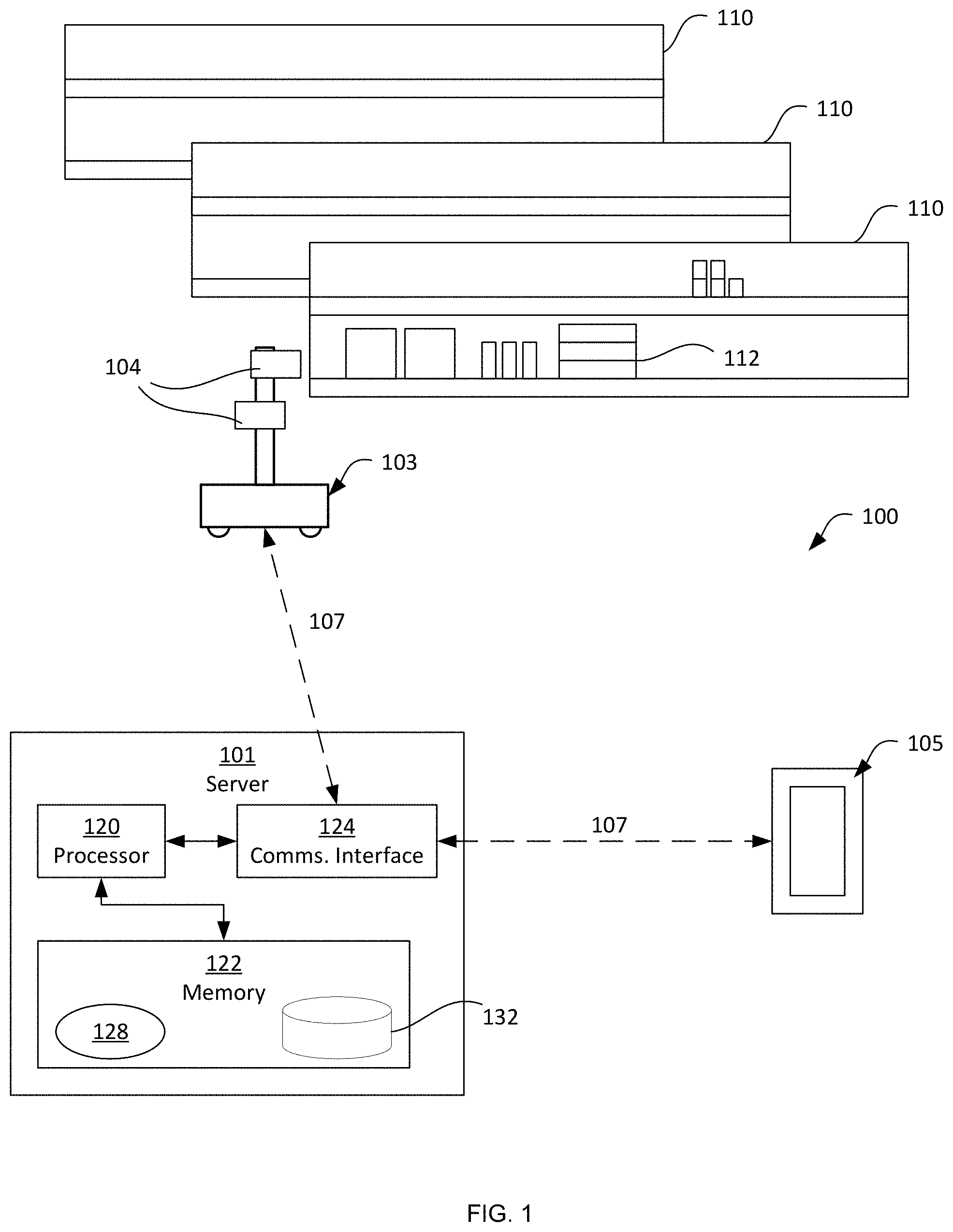
FIG. 1 is a schematic of a mobile automation system.
FIG. 2 is a block diagram of certain internal hardware components of the server in the system of FIG. 1.
FIG. 3 is a flowchart of a method of gap detection.
FIG. 4 is a flowchart of a method of back of shelf detection.
FIG. 5 is an example image obtained in the performance of the method of FIG. 4.
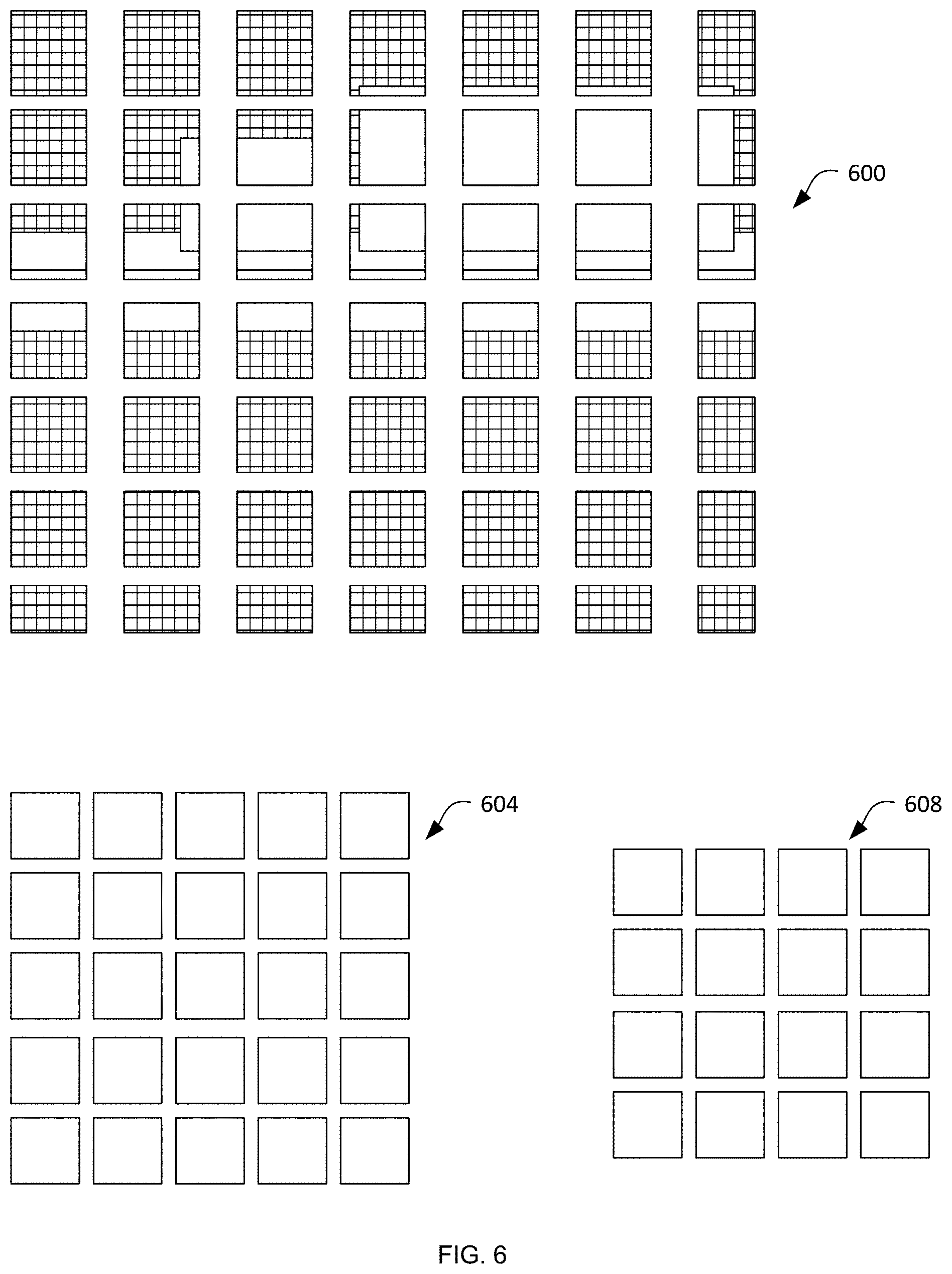
FIG. 6 illustrates decomposed and scaled versions of the image of FIG. 5.
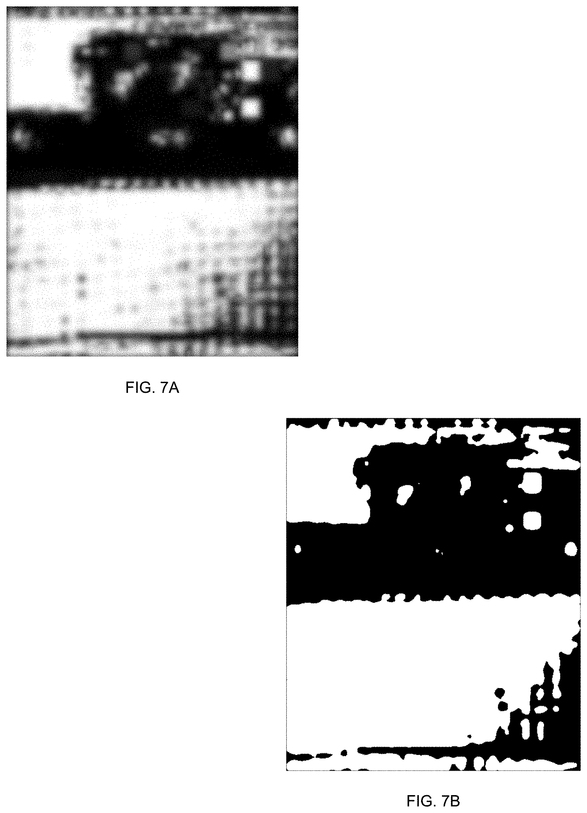
FIGS. 7A and 7B are a back of shelf score mask and a back of shelf mask following application of a score threshold, respectively.
FIGS. 8-10B illustrate certain operations performed on the mask of FIG. 7B in the performance of the method of FIG. 3.
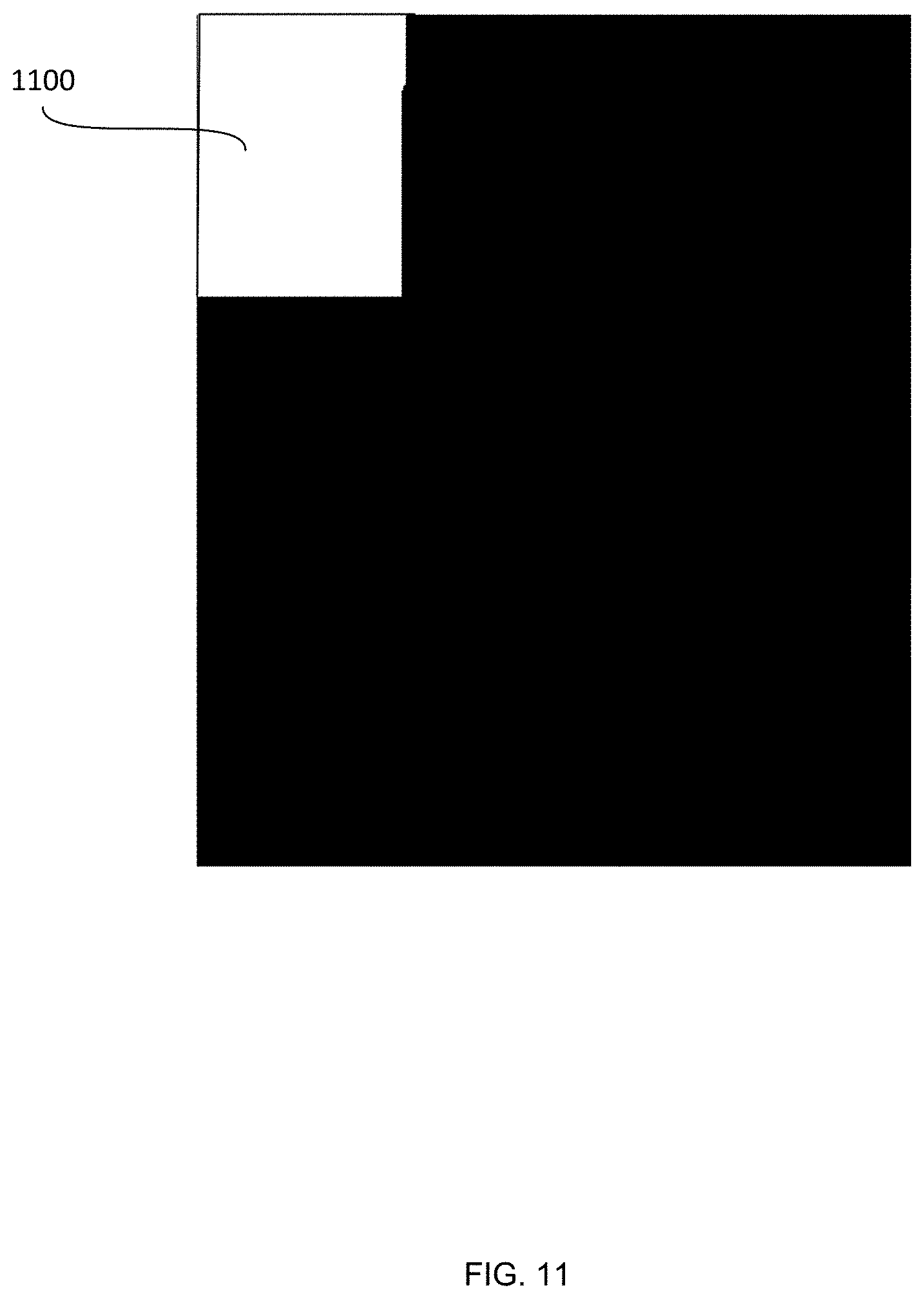
FIG. 11 is a gap mask resulting from the performance of the method of FIG. 3.
Skilled artisans will appreciate that elements in the figures are illustrated for simplicity and clarity and have not necessarily been drawn to scale. For example, the dimensions of some of the elements in the figures may be exaggerated relative to other elements to help to improve understanding of embodiments of the present invention.
The apparatus and method components have been represented where appropriate by conventional symbols in the drawings, showing only those specific details that are pertinent to understanding the embodiments of the present invention so as not to obscure the disclosure with details that will be readily apparent to those of ordinary skill in the art having the benefit of the description herein.
DETAILED DESCRIPTION
Environments such as warehouses, retail locations (e.g. grocery stores) and the like typically contain a wide variety of products supported on shelves, for selection and purchase by customers. As a result, the composition of the set of products supported by any given shelf module varies over time, as products are removed and, in some cases, replaced by customers. Products that have been partially or fully depleted typically require restocking, and products that have been incorrectly replaced (referred to as "plugs") typically require relocation to the correct position on the shelves. The detection of restocking or plug issues is conventionally performed by human employees, via visual assessment of the shelves and manual barcode scanning. This form of detection is labor-intensive and therefore costly, as well as error-prone.
Attempts to automate the detection of product status issues such as those mentioned above are complicated by the fluid nature of the environment in which an autonomous data capture system is required to operate. Among other difficulties, digital images of the shelves vary in quality depending on the available lighting, the presence of visual obstructions, and the like. Further, the breadth of products present on the shelves and the variations in their positioning on the shelves reduces the accuracy of machine-generated status detection.
Examples disclosed herein are directed to a method of detecting a back of a shelf for supporting objects, comprising: obtaining an image depicting a shelf having a shelf edge and a support surface extending from the shelf edge to a shelf back; decomposing the image into a plurality of patches; for each patch: generating a feature descriptor; based on the feature descriptor, assigning one of a shelf back classification and a non-shelf back classification to the patch; generating a mask corresponding to the image, the mask containing an indication of the classification assigned to each of the patches; and presenting the mask.
FIG. 1 depicts a mobile automation system 100 in accordance with the teachings of this disclosure. The system 100 includes a server 101 in communication with at least one mobile automation apparatus 103 (also referred to herein simply as the apparatus 103) and at least one mobile device 105 via communication links 107, illustrated in the present example as including wireless links. The system 100 is deployed, in the illustrated example, in a retail environment including a plurality of shelf modules 110 each supporting a plurality of products 112. The shelf modules 110 are typically arranged in a plurality of aisles, each of which includes a plurality of modules aligned end-to-end. More specifically, the apparatus 103 is deployed within the retail environment, and communicates with the server 101 (via the link 107) to navigate, either fully or partially autonomously, the length of at least a portion of the shelves 110. The apparatus 103 is equipped with a plurality of navigation and data capture sensors 104, such as image sensors (e.g. one or more digital cameras), and depth sensors (e.g. one or more Light Detection and Ranging (LIDAR) sensors), structured light sensors, ultrasonic sensors, among others, and is further configured to employ the sensors to capture shelf data. In the present example, the apparatus 103 is configured to capture a series of digital images of the shelves 110, as well as a series of depth measurements, each describing the distance and direction between the apparatus 103 and one or more points on a shelf 110, such as the shelf itself or the product disposed on the shelf.
The server 101 includes a special purpose imaging controller, such as a processor 120, specifically designed to control the mobile automation apparatus 103 to capture data, obtain the captured data via the communications interface 124 and store the captured data in a repository 132 in the memory 122. The server 101 is further configured to perform various post-processing operations on the captured data and to detect the status of the products 112 on the shelves 110. When certain status indicators are detected by the imaging processor 120, the server 101 is also configured to transmit status notifications (e.g. notifications indicating that products are out-of-stock, low stock or misplaced) to the mobile device 105. The processor 120 is interconnected with a non-transitory computer readable storage medium, such as a memory 122, having stored thereon computer readable instructions for identifying back of shelf regions and gaps from captured image data, as discussed in further detail below. The memory 122 includes a combination of volatile (e.g. Random Access Memory or RAM) and non-volatile memory (e.g. read only memory or ROM, Electrically Erasable Programmable Read Only Memory or EEPROM, flash memory). The processor 120 and the memory 122 each comprise one or more integrated circuits. In an embodiment, the processor 120, further includes one or more central processing units (CPUs) and/or graphics processing units (GPUs). In an embodiment, a specially designed integrated circuit, such as a Field Programmable Gate Array (FPGA), is designed to perform the identification of back of shelf regions and gaps from captured image data discussed herein, either alternatively or in addition to the imaging controller/processor 120 and memory 122. As those of skill in the art will realize, the mobile automation apparatus 103 also includes one or more controllers or processors and/or FPGAs, in communication with the controller 120, specifically configured to control navigational and/or data capture aspects of the apparatus 103 either alternatively or in addition to the functionality of the controller 120 discussed herein.
The server 101 also includes a communications interface 124 interconnected with the processor 120. The communications interface 124 includes suitable hardware (e.g. transmitters, receivers, network interface controllers and the like) allowing the server 101 to communicate with other computing devices--particularly the apparatus 103 and the mobile device 105--via the links 107. The links 107 may be direct links, or links that traverse one or more networks, including both local and wide-area networks. The specific components of the communications interface 124 are selected based on the type of network or other links that the server 101 is required to communicate over. In the present example, a wireless local-area network is implemented within the retail environment via the deployment of one or more wireless access points. The links 107 therefore include both wireless links between the apparatus 103 and the mobile device 105 and the above-mentioned access points, and a wired link (e.g. an Ethernet-based link) between the server 101 and the access point.
The memory 122 stores a plurality of applications, each including a plurality of computer readable instructions executable by the processor 120. The execution of the above-mentioned instructions by the processor 120 configures the server 101 to perform various actions discussed herein. The applications stored in the memory 122 include a control application 128, which may also be implemented as a suite of logically distinct applications. In general, via execution of the control application 128 or subcomponents thereof, the processor 120 is configured to implement various functionality. The processor 120, as configured via the execution of the control application 128, is also referred to herein as the controller 120. As will now be apparent, some or all of the functionality implemented by the controller 120 described below may also be performed by preconfigured hardware elements (e.g. one or more ASICs) rather than by execution of the control application 128 by the processor 120.
In the present example, in particular, the server 101 is configured via the execution of the control application 128 by the processor 120, to process image and depth data captured by the apparatus 103 to identify portions of the captured data depicting a back of a shelf 110, and to detect gaps between the products 112 based on those identified portions.
Turning now to FIG. 2, before describing the operation of the application 128 to identify back of shelf regions and gaps from captured image data, certain components of the application 128 will be described in greater detail. As will be apparent to those skilled in the art, in other examples the components of the application 128 may be separated into distinct applications, or combined into other sets of components. Some or all of the components illustrated in FIG. 2 may also be implemented as dedicated hardware components, such as one or more Application-Specific Integrated Circuits (ASICs) or FPGAs. For example, in one embodiment, to improve reliability and processing speed, at least some of the components of FIG. 2 are programmed directly into the imaging controller 120, which may be an FPGA or an ASIC having circuit and memory configuration specifically designed to optimize image processing of high volume of sensor data received from the mobile automation apparatus 103. In such an embodiment, some or all of the control application 128, discussed below, is an FPGA or an ASIC chip.
The control application 128 includes a back of shelf detector 200 (also referred to herein simply as a detector 200), as well as a gap detector 204. In brief, the detector 200 is configured to process input image data captured by the apparatus 103 to detect areas of the image data that depict a back of the shelves 110. The gap detector 204, meanwhile, is configured to receive the output of the detector 200 in the form of a back-of-shelf mask, and to identify portions of the back-of-shelf mask that correspond to gaps between products 112 on the shelves 110.
More specifically, the detector 200 includes a pre-processor 210 configured to decompose input image data; a feature generator 212 configured to generate feature descriptors for the decomposed image data generated by the pre-processor 120; a classifier 214 configured to assign back of shelf or non-back of shelf classifications to the decomposed image data based on the feature descriptors; and a mask generator 216 configured to generate a back of shelf mask based on the decomposed image data and the output of the classifier 214.
The gap detector 204 includes a shelf edge detector 220 configured to detect or otherwise obtain a location of a shelf edge relative to the input image data; a region segmentor 224 configured to select, based in part of the shelf edge location, areas of the back of shelf mask which may correspond to gaps between the products 112; a mask generator 228 configured to process the segmented back of shelf mask to generate a gap mask; and a validator 232 configured to validate the gap mask based on depth measurements obtained from the apparatus 103.
Turning to FIG. 3, a method 300 of detecting gaps in an image of a shelf having a shelf edge and a support surface for supporting objects extending from the shelf edge to a shelf back is shown. The method 300 will be described in conjunction with its performance on the system 100 as described above.
As will be apparent, the shelves 110 typically include substantially horizontal (when installed for use) support surfaces extending between a shelf edge and a shelf back. The support surfaces support the products 112, and the shelf back may be visible in between the products 112, as well as over top of the products 112. At block 305, the server 101 is configured to obtain a back of shelf mask generated from an image of a shelf 110 (e.g. captured by the apparatus 103) and containing, for each of a plurality of areas of the mask, indications of a classification assigned to the area and selected from a shelf back classification and a non-shelf back classification. In other words, the back of shelf mask obtained at block 305 identifies areas of an imaged shelf 110 in which the back of the shelf 110 is visible.
In the present example, the back of shelf mask is obtained by generating the back of shelf mask at the server 101, and in particular with the back of shelf detector 200. Turning to FIG. 4, a method of generating a back of shelf mask is illustrated. In other examples, block 305 of method 300 can be performed by the gap detector 204, by retrieving a previously generated back of shelf mask from the memory 122.
Referring to FIG. 4, the generation of a back of shelf mask begins at block 405, at which the detector 200 is configured to obtain a digital image of the shelf 110, for example captured by the apparatus 103 and stored in the repository 132. An example image 500 is illustrated in FIG. 5, depicting a portion of a shelf 110. In particular, the image 500 depicts a shelf edge 504 and a shelf back 508, as well as a support surface 512 extending the between the shelf edge 504 and the shelf back 508 and supporting products 112. The shelf edge 504 abuts one side of the support surface 512 extending along a horizontal plane of the shelf 110 and defines a vertical surface that is parallel to the shelf back 508. As illustrated in FIG. 5, the shelf back 508 is patterned; as will be apparent, the shelf back may have a wide variety of appearances.
Returning to FIG. 4, at block 410 the detector 200 is configured to decompose the image 500 obtained at block 405. More specifically, in the present example the pre-processor 210 is configured to decompose the image into a plurality of patches. When the image 500 is in color, the pre-processor 210 can also convert the image 500 to greyscale, and may also normalize contrast in the image 500. In addition, in the present example, the pre-processor 210 is configured to generate a plurality of scaled versions of the image 500, and to decompose each scaled version into a plurality of patches. The generation of scaled versions of the image 500 (that is, versions of the image depicting the same region of the shelf 100 but at a differing resolutions; in other words, at different pixel densities) allows subsequent processing to account for varying distance between the apparatus 103 and the shelf 100 at the time of capture. The generation of scaled versions may be omitted in other examples.
Turning to FIG. 6, three scaled versions of the image 500 are illustrated, following decomposition into patches, each patch containing a fragment of the original image. In particular, a first set of patches 600 results from the decomposition of a full-scale version of the image 500. A second set of patches 604 results from the decomposition of a downsampled version of the image 500, and a third set of patches 608 results from the decomposition of a further downsampled version of the image 500. In other examples, a number of scales greater or smaller than three may be generated. The second and third sets of patches have been illustrated without the content of the image 500 for simplicity.
As shown in FIG. 6, the patches have the same resolution at each scale, and therefore different scales are decomposed into different numbers of patches. In the present example, each patch (at every scale) has a resolution of 32.times.32 pixels. The patches may have other resolutions in other examples; in general, the pre-processor 210 is preconfigured with a patch size determined (e.g. empirically) to be sufficiently large to encompass recognizable (as will be discussed below) features of the shelf back 508, and sufficiently small to avoid capturing both back of shelf areas and other areas of the image 500 in a majority of the patches.
Although not illustrated in FIG. 6, in some examples the patches overlap with one another. For example, the above-mentioned 32.times.32 pixel patches may overlap with adjacent patches by a preconfigured distance (e.g. 5 pixels).
Returning to FIG. 4, at block 415 the detector 200 is configured to determine whether all scales (if scaled versions of the image 500 are being employed) have been processed. In this example performance of the method 305, no processing has been performed, and the determination at block 415 is therefore negative. Following a negative determination at block 415, the performance of the method 305 proceeds to block 420.
At block 420, the feature generator 212 is configured to generate a feature descriptor for each of the patches generated at block 410. Various feature descriptors may be employed. In the present example, the feature descriptor is a histogram of oriented gradients (HOG) descriptor. To generate the HOG descriptors, the feature generator 212 divides each patch into cells (e.g. 8.times.8 pixel cells). For each pixel (64 per cell, in the present example) of each cell, the feature generator 212 then generates a gradient vector indicating the angle of the greatest change in intensity between the pixel and its neighbors, as well as the magnitude of the change in intensity. Having obtained the above-mentioned vectors, the feature generator 212 is configured to build a histogram, with bins corresponding to ranges of angles (e.g. 9 bins each accounting for an unsigned range of 20 degrees). The magnitude of each vector is added to the bin encompassing the vector's angle; in some example implementations, vectors with angles near the boundary between two adjacent bins may have their magnitudes divided between those bins. The resulting histogram for each cell is thus a 1.times.N vector, where N is the number of histogram bins (9 in the present example, though other numbers of bins may also be employed), containing the magnitudes assigned to each of the bins.
The feature generator 212 is then configured to concatenate the feature vectors of the cells for each patch into a single vector. Thus, in the example mentioned above, in which each 32.times.32 patch is divided into sixteen 8.times.8 cells, the feature generator 212 generates a 1.times.144 feature descriptor. In some examples, additional processing is performed on the cell-specific vectors mentioned above before concatenation. Specifically, in such examples the feature generator 212 is configured to perform a normalization operation on each of a plurality of cell blocks encompassing multiple cells (e.g. 2.times.2 cells). The normalization operation compensates for lighting and contrast variations throughout the image, and includes stacking the vectors for each cell (thus, resulting in a 36-element vector in this example). The feature generator 212 is then configured to determine the magnitude, also referred to as the L2 norm, of the stacked vector, which is the square root of the sum of the squares of each vector element. The feature generator 212 is configured to divide each of the elements in the stacked vector by the above-mentioned magnitude.
The feature generator 212 is configured to repeat the above-mentioned normalization process for each of a plurality of additional blocks of cells. In the present example, the blocks of cells overlap with each other by a width and/or height of one cell. The resulting descriptor for each patch when block normalization is employed as discussed above is 1.times.324: with 32.times.32 pixel patches, each patch is divided into a grid of 4.times.4 cells, which are grouped into a grid of 3.times.3 overlapping blocks. Each of the nine blocks yields a 36-element vector, for a total of (9.times.36)=324 elements.
Following the generation of feature descriptors as discussed above, at block 425, a classification is assigned to each patch for a given scale. The classification is one of a back of shelf classification and a non-back of shelf classification, and may be assigned in a variety of ways. In the present example, the feature generator 212 is configured to stack the feature descriptors for each patch into a single M.times.144 descriptor (or a M.times.324 descriptor when block normalization is employed as described above) corresponding to the entire image, where M is the number of patches. The stacked descriptor is provided as an input to the classifier 214. In the present example, the classifier is a trained neural network, which accepts the stacked descriptor as input and generates, as an output, a pair of scores for each patch. The pair of scores includes a back of shelf score indicating a level of confidence that the relevant patch depicts the shelf back 508, and a non-back of shelf score indicating a level of confidence that the relevant patch does not depict the shelf back 508. The classifier 214 is configured, in the present example, to select the greatest of the scores for presentation as output to the mask generator 216. More specifically, when the greater score corresponds to the back of shelf classification, the score is selected for further processing. When the greater score corresponds to the non-back of shelf classification, the score is selected and subtracted from one before being presented for further processing, such that all the scores employed downstream of classification represent the confidence of a back of shelf classification for their respective patches.
Once the patch classification for a given image scale is complete, the performance of method 305 returns to block 415. Thus, the feature descriptor generation and classification is repeated for each set of patches shown in FIG. 6, following which the determination at block 415 is affirmative.
In response to an affirmative determination at block 415, the performance of the method 305 proceeds to block 430. At block 430, the mask generator 216 is configured to combine the patch classifications from each scaled version of the image into a single score mask. The generation of classification scores for the patches at each scale results in a grid of patch scores, for example with the score being assigned as an intensity value to a point located at the center of the patch. At block 430, the mask generator 216 is configured to return the score grids from each scale to a single common scale (e.g. the original scale of the image obtained at block 405). FIG. 7A illustrates an example of a score mask generated at block 430, in which the lighter areas represent a greater degree of confidence that the corresponding areas of the original image depict the shelf back 508.
The mask generator 216 is then configured to apply a threshold to the score mask shown in FIG. 7A, to convert the score mask into a binary mask indicating whether each pixel depicts the shelf back 508 or does not depict the shelf back 508. Any pixels in the score mask that do not meet the threshold are set to a low intensity, and any pixels that do meet the threshold are set to a high intensity. FIG. 7B depicts the result of applying the score threshold to the score mask of FIG. 7A. When the back of shelf mask has been generated, performance of the method 300 continues.
Returning to FIG. 3, the performance of block 305 is completed when the gap detector 204 obtains the back of shelf mask from the detector 200. As discussed above, the back of shelf mask contains indications (in the form of high or low intensity values), for each of a plurality of areas of the back of shelf mask, of a classification assigned to the area and selected from a shelf back classification and a non-shelf back classification. Referring briefly to FIG. 7B, the white areas are those having the back of shelf classification, while the black areas are those having the non-back of shelf classification.
At block 310, the gap detector 204, having obtained the back of shelf mask, is configured to obtain a location of the shelf edge 504 relative to the back of shelf mask. In some examples, the shelf edge location is stored in the memory 122, and at block 310 the gap detector 204 is configured to retrieve the shelf edge location from memory. For example, the shelf edge location may be stored in a frame of reference corresponding to the retail environment itself. In such examples, the image obtained at block 405 may be registered to the common frame of reference by another component of the control application 128 (for example, using navigational data generated by the apparatus 103), and thus the back of shelf mask is also registered to the common frame of reference.
In other examples, the gap detector obtains the location of the shelf edge by detecting the shelf edge location from depth measurements obtained by the apparatus 103 corresponding to the image obtained at block 405. The depth measurements are registered to the images obtained by the apparatus 103, and thus the location of each depth measurement relative to the original image and the back of shelf mask is known. At block 310, in such examples, the shelf edge detector 220 is configured to detect the shelf edge from the depth measurements, for example by identifying a contiguous set of depth measurements located within a threshold distance of a particular plane. The shelf edge, when detected, may be overlaid on the back of shelf mask as a bounding box, as shown in FIG. 8, in which the shelf edge is illustrated as an overlay 800.
At block 315, the region segmentor 224 is configured to select an area of the back of shelf mask, classified as back of shelf, that is adjacent to the shelf edge location (i.e. to the overlay 800, in the present example). In particular, the region segmentor 224 is configured to locate any back of shelf areas of the mask that are within a preconfigured threshold distance of the upper side of the shelf edge bounding box 800. As shown in FIG. 8, the area surrounded by the bounding box 804 satisfies the threshold distance, and the region segmentor 224 is therefore configured to select the area 804 at block 315. The area 804, and any other areas satisfying the distance threshold, may be selected using a variety of mechanisms. As illustrated in FIG. 8, the area 804 is selected as the rectangular area extending away from the overlay 800 until a non-back of shelf area is reached. In other examples, the region segmentor 224 is instead configured to adjust the selected area to maximize the area covered by the selection. In the example of FIG. 8, such a selection would include a rectangular area with a narrower base and a greater height. In further examples, the region segmentor 224 is configured to select more complex shapes than the illustrated rectangular bounding box 804.
As will now be apparent, other areas, such as the area 808, are also within the threshold distance of the shelf edge overlay 800. However, the segmentor 224 is configured, in the present example, to disregard any areas portions of the mask having areas below a threshold. Such small portions may indicate, for example, an incorrect classification of a product 112 as depicting the shelf back 508 due to lighting or other image capture artifacts.
The region segmentor 224 is also configured, at block 315, to disregard any portions of the mask below the shelf edge overlay 800, as well as any portions beyond (e.g. left or right of) the ends of a shelf edge overlay, when the shelf edge overlay does not traverse the entire mask. Thus, in the present example, the region 812 of the mask is disregarded during the performance of block 315. Regions of the mask that are disregarded can be deleted (reducing the size of the mask), or simply assigned a non-gap classification without further analysis. Regions such as the region 812 are disregarded because, in the absence of a shelf edge overlay below the region 812, there is too little information available to the gap detector 204 to determine whether the region 812 is adjacent to the upper side of a shelf edge. The region 812 is instead assessed during a further performance of the method 300, beginning with an image of a different portion of the shelf 110 (specifically, a portion below that resulting in the mask shown in FIG. 8).
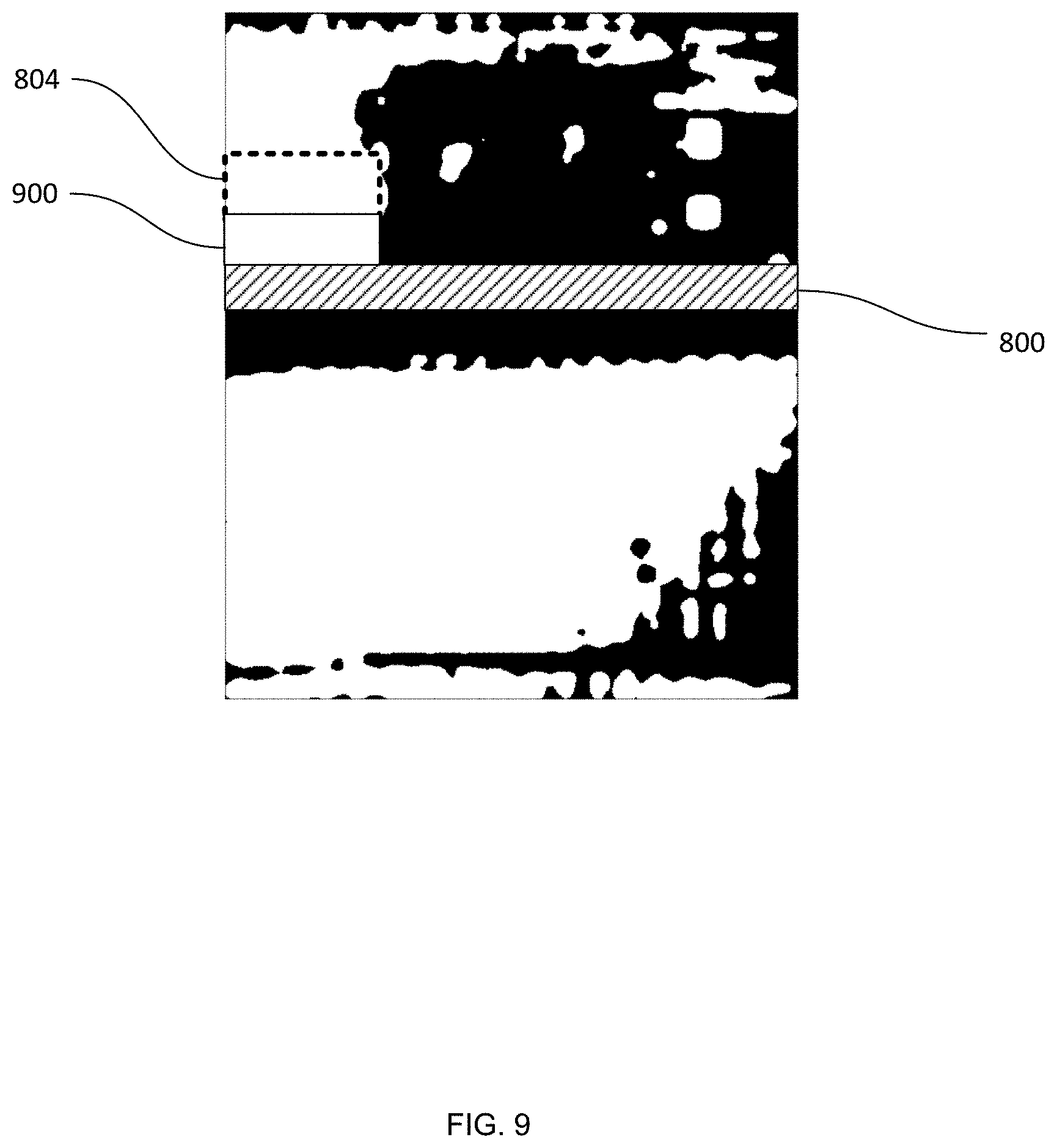
At block 320, the region segmentor 224 is configured to generate a joining area between the shelf edge overlay 800 and the selected area 804. Referring to FIG. 9, a joining area 900 is illustrated, extending from the shelf edge overlay 800 to the selected area 804. The joining area 900, as will be seen below, serves to classify the shelf support surface, if visible in the image, as back of shelf (and thus as a gap).
The selected area 804 and the joining area 900 are assigned a gap classification by the mask generator 228. In the present example, the mask generator 228 is also configured to expand the selected area 804. As seen in FIG. 9, a portion of the back of shelf mask classified as back of shelf extends up from the selected area, as well as towards the right along the top of the mask. The mask generator 228 is configured to perform a region growth operation beginning at the centroid of the selected area 804. As will be apparent to those skilled in the art, the region growth operation determines, for each point outwards from the starting point, whether to include the point in a region (e.g. based on the intensity of the point under consideration and its neighbors). The region growth operation serves to join discrete (i.e. separated from each other) back of shelf-classified areas that are likely to represent contiguous portions of the shelf back 508, but were not classified as such due to imaging artifacts.
Turning to FIG. 10A, a gap mask 1000 is illustrated following the completion of the region growth operation. As illustrated, a contiguous area 1004 is classified as a gap, encompassing both the area 804 and the joining area 900, as well as several areas classified as back of shelf that were previously distinct (as shown in FIGS. 8 and 9). As also shown in FIG. 10A, the mask generator 228 is configured to assign the previously discussed disregarded areas a non-gap classification (a low intensity, in the present example).
Referring again to FIG. 3, at block 325 the gap detector 204 is configured to perform a depth-based sensor validation of the gap mask illustrated in FIG. 10A. In particular, the validator 232 is configured to divide the gap mask into a plurality of vertical slices. Two example slices 1008 and 1012 are illustrated in FIG. 10A, and are shown in isolation in FIG. 10B. In the present example, the slices generated from the gap mask are 100 pixels in width; however, in other embodiments another suitable slice width can be employed. The slices can also overlap in some examples. The height of the slices is selected by the validator 232 to extend substantially from the shelf edge location (not shown in FIG. 10A) to the upper edge of the gap mask 1000. In other examples, in which more than one shelf is depicted in the initial image, the height of the vertical slices is selected by the validator 232 to extend from the upper side of one shelf edge location to the lower side of the adjacent shelf edge location. In other words, a plurality of sets of vertical slices are generated, each corresponding to the area adjacent and above a particular shelf.
For each slice, the validator 232 is configured to determine a proportion of the point depths corresponding to that slice that exceed a median point depth for the slice. In other words, the validator 232 is configured to assess whether the depth measurements corresponding to a given slice are concentrated near or on a plane corresponding to the shelf back 508, or whether the depth measurements are dispersed at various depths between the shelf back 508 and the shelf edge 504 (indicating the presence of a product 112 in the slice).
In the present example, the validator 232 determines a median of the subset of depth sensor measurements (obtained earlier and registered to the mask as discussed above) within each slice, and further determines what proportion of the depth measurements exceed the median. For example, the validator 232 is configured to generate a histogram of the depth measurements within each slice and determine the number of
References
D00000
D00001
D00002
D00003
D00004
D00005
D00006
D00007
D00008
D00009
D00010
D00011
XML
uspto.report is an independent third-party trademark research tool that is not affiliated, endorsed, or sponsored by the United States Patent and Trademark Office (USPTO) or any other governmental organization. The information provided by uspto.report is based on publicly available data at the time of writing and is intended for informational purposes only.
While we strive to provide accurate and up-to-date information, we do not guarantee the accuracy, completeness, reliability, or suitability of the information displayed on this site. The use of this site is at your own risk. Any reliance you place on such information is therefore strictly at your own risk.
All official trademark data, including owner information, should be verified by visiting the official USPTO website at www.uspto.gov. This site is not intended to replace professional legal advice and should not be used as a substitute for consulting with a legal professional who is knowledgeable about trademark law.