Prosthetic heart valve composed of composite fibers
Eppihimer , et al.
U.S. patent number 10,716,671 [Application Number 15/193,794] was granted by the patent office on 2020-07-21 for prosthetic heart valve composed of composite fibers. This patent grant is currently assigned to Boston Scientific Scimed, Inc.. The grantee listed for this patent is Boston Scientific SciMed, Inc.. Invention is credited to Peter G. Edelman, Michael Eppihimer.

| United States Patent | 10,716,671 |
| Eppihimer , et al. | July 21, 2020 |
Prosthetic heart valve composed of composite fibers
Abstract
A prosthetic heart leaflet includes a fiber-reinforced structure including a plurality of composite fibers. Each composite fiber includes a core fiber and a sheathing fiber disposed about the core fiber, wherein the core fiber or the sheathing fiber has a curvilinear shape.
| Inventors: | Eppihimer; Michael (Franklin, MA), Edelman; Peter G. (Maple Grove, MN) | ||||||||||
|---|---|---|---|---|---|---|---|---|---|---|---|
| Applicant: |
|
||||||||||
| Assignee: | Boston Scientific Scimed, Inc.
(Maple Grove, MN) |
||||||||||
| Family ID: | 56373178 | ||||||||||
| Appl. No.: | 15/193,794 | ||||||||||
| Filed: | June 27, 2016 |
Prior Publication Data
| Document Identifier | Publication Date | |
|---|---|---|
| US 20170000610 A1 | Jan 5, 2017 | |
Related U.S. Patent Documents
| Application Number | Filing Date | Patent Number | Issue Date | ||
|---|---|---|---|---|---|
| 62188201 | Jul 2, 2015 | ||||
| Current U.S. Class: | 1/1 |
| Current CPC Class: | A61F 2/2409 (20130101); A61F 2/2469 (20130101); A61F 2/2412 (20130101); A61F 2250/0018 (20130101); A61F 2240/001 (20130101); A61F 2230/0091 (20130101); A61F 2230/0069 (20130101) |
| Current International Class: | A61F 2/24 (20060101) |
| Field of Search: | ;428/377 |
References Cited [Referenced By]
U.S. Patent Documents
| 4016714 | April 1977 | Crandall |
| 4340091 | July 1982 | Davis et al. |
| 4753652 | June 1988 | Langer et al. |
| 5296292 | March 1994 | Butters |
| 5476507 | December 1995 | Wakabayashi et al. |
| 5674286 | October 1997 | D'Alessio et al. |
| 5679299 | October 1997 | Gilbert et al. |
| 5688597 | November 1997 | Kohno |
| 5740051 | April 1998 | Sanders, Jr. et al. |
| 5843158 | December 1998 | Lenker et al. |
| 6165215 | December 2000 | Rottenberg et al. |
| 6726715 | April 2004 | Sutherland |
| 6953332 | October 2005 | Kurk et al. |
| 7335264 | February 2008 | Austin et al. |
| 7517353 | April 2009 | Weber |
| 7521296 | April 2009 | Wood et al. |
| 7615335 | November 2009 | Shelnut et al. |
| 7786670 | August 2010 | Veres et al. |
| 7988900 | August 2011 | Beith et al. |
| 8324290 | December 2012 | Desai et al. |
| 8361144 | January 2013 | Fish et al. |
| 8590747 | November 2013 | Keller et al. |
| 8845580 | September 2014 | Gellman et al. |
| 8864816 | October 2014 | Flanagan et al. |
| 8945212 | February 2015 | Bruchman et al. |
| 8975372 | March 2015 | Ju et al. |
| 9056006 | June 2015 | Edelman et al. |
| 9074318 | July 2015 | Chou |
| 9255929 | February 2016 | Jiang et al. |
| 9481949 | November 2016 | Zhang et al. |
| 9554900 | January 2017 | Bruchman et al. |
| 9737400 | August 2017 | Fish et al. |
| 9814572 | November 2017 | Edelman et al. |
| 9944529 | April 2018 | Zhang et al. |
| 9987130 | June 2018 | Weber |
| 10195023 | February 2019 | Wrobel |
| 10299915 | May 2019 | Edelman et al. |
| 10314696 | June 2019 | Wulfman et al. |
| 10368982 | August 2019 | Weber et al. |
| 10413403 | September 2019 | Boden et al. |
| 10426609 | October 2019 | Edelman et al. |
| 10433955 | October 2019 | Edelman et al. |
| 2001/0025196 | September 2001 | Chinn et al. |
| 2002/0082689 | June 2002 | Chinn et al. |
| 2003/0055496 | March 2003 | Cai et al. |
| 2003/0078652 | April 2003 | Sutherland |
| 2003/0097175 | May 2003 | O'connor et al. |
| 2003/0171802 | September 2003 | Wilder et al. |
| 2003/0183982 | October 2003 | Jansen et al. |
| 2004/0015233 | January 2004 | Jansen et al. |
| 2004/0022939 | February 2004 | Kim et al. |
| 2005/0228486 | October 2005 | Case |
| 2006/0190074 | August 2006 | Hill et al. |
| 2007/0118210 | May 2007 | Pinchuk et al. |
| 2007/0144124 | June 2007 | Schewe et al. |
| 2007/0232169 | October 2007 | Strickler et al. |
| 2007/0254005 | November 2007 | Pathak et al. |
| 2008/0045420 | February 2008 | Karagianni et al. |
| 2009/0041978 | February 2009 | Sogard et al. |
| 2009/0054969 | February 2009 | Salahieh |
| 2009/0117334 | May 2009 | Sogard et al. |
| 2009/0149673 | June 2009 | Zhang et al. |
| 2009/0155335 | June 2009 | Oshaughnessey et al. |
| 2009/0324679 | December 2009 | Ippoliti et al. |
| 2010/0023104 | January 2010 | Desai et al. |
| 2010/0179298 | July 2010 | Faust et al. |
| 2010/0249922 | September 2010 | Li et al. |
| 2011/0022160 | January 2011 | Flanagan et al. |
| 2011/0208299 | August 2011 | Marissen et al. |
| 2011/0305898 | December 2011 | Zhang et al. |
| 2012/0101567 | April 2012 | Jansen |
| 2012/0258313 | October 2012 | Wen et al. |
| 2012/0290082 | November 2012 | Quint et al. |
| 2013/0150957 | June 2013 | Weber et al. |
| 2013/0211508 | August 2013 | Lane et al. |
| 2013/0274874 | October 2013 | Hammer et al. |
| 2014/0005771 | January 2014 | Braido et al. |
| 2014/0005772 | January 2014 | Edelman et al. |
| 2014/0018440 | January 2014 | Boden et al. |
| 2014/0088716 | March 2014 | Zubok et al. |
| 2014/0163671 | June 2014 | Bruchman et al. |
| 2014/0180402 | June 2014 | Bruchman et al. |
| 2014/0322512 | October 2014 | Pham |
| 2015/0005869 | January 2015 | Soletti et al. |
| 2015/0182332 | July 2015 | Edelman et al. |
| 2015/0265392 | September 2015 | Flanagan et al. |
| 2016/0296322 | October 2016 | Edelman |
| 2016/0296323 | October 2016 | Wulfman |
| 2016/0296325 | October 2016 | Edelman |
| 2017/0014227 | January 2017 | Boden et al. |
| 2017/0071729 | March 2017 | Wrobel |
| 2017/0156854 | June 2017 | Hammer |
| 2017/0231758 | August 2017 | Bruchman et al. |
| 2017/0266350 | September 2017 | Jiang et al. |
| 2017/0333185 | November 2017 | Weber et al. |
| 2018/0049869 | February 2018 | Edelman et al. |
| 2018/0303972 | October 2018 | Delaney, Jr. et al. |
| 2019/0262131 | August 2019 | Wulfman et al. |
| 2019/0350703 | November 2019 | Weber et al. |
| 1449266 | Oct 2003 | CN | |||
| 1874799 | Dec 2006 | CN | |||
| 101690683 | Apr 2010 | CN | |||
| 103628147 | Mar 2014 | CN | |||
| 104780952 | Jul 2015 | CN | |||
| 3316818 | May 2019 | EP | |||
| H0654868 | Mar 1994 | JP | |||
| 2013144009 | Jul 2013 | JP | |||
| 0224119 | Mar 2002 | WO | |||
| 02074201 | Sep 2002 | WO | |||
| 2004080346 | Feb 2005 | WO | |||
| 2005039664 | May 2005 | WO | |||
| 2006000763 | Jan 2006 | WO | |||
| 2008097592 | Aug 2008 | WO | |||
| 2009038761 | Mar 2009 | WO | |||
| 2010020660 | Feb 2010 | WO | |||
| 2010048281 | Apr 2010 | WO | |||
| 2014008207 | Jan 2014 | WO | |||
| 2014143866 | Sep 2014 | WO | |||
| 2014149319 | Sep 2014 | WO | |||
| 2014158444 | Oct 2014 | WO | |||
| 2016025945 | Feb 2016 | WO | |||
| 2016164197 | Oct 2016 | WO | |||
| 2016164209 | Oct 2016 | WO | |||
| 2017004035 | Jan 2017 | WO | |||
| 2017011392 | Jan 2017 | WO | |||
| 2017048575 | Mar 2017 | WO | |||
| 2017200920 | Nov 2017 | WO | |||
| 2018200378 | Nov 2018 | WO | |||
Other References
|
"International Search Report and Written Opinion," for PCT application No. PCT/US2016/050691 dated Dec. 19, 2016 (14 pages). cited by applicant . "Non-Final Office Action," for U.S. Appl. No. 14/656,044 dated Mar. 17, 2017 (34 pages). cited by applicant . "Response to Communication Pursuant to Article 94(3) EPC," for European Patent Application No. 13739321.1 filed with the EPO Jan. 2, 2017 (37 pages). cited by applicant . Aksoy, Ayse E. et al., "Surface Modification of Polyurethanes with Covalent Immobilization of Heparin," Macromolecular Symposia, vol. 269, Issue 1, pp. 145-153, Aug. 2008 (9 pages). cited by applicant . Alferiev, Ivan et al., "Prevention of polyurethane valve cusp calcification with covalently attached bisphosphonate diethylamino moieties," J Biomed Mater Res 66A: 385-395, 2003 (11 pages). cited by applicant . Athappan, Ganesh et al., "Influence of Transcatheter Aortic Valve Replacement Strategy and Valve Design on Stroke After Transcatheter Aortic Valve Replacement: A Meta-Analysis and Systematic Review of Literature," J Am Coll Cardiol. 2014;63(20):2101-2110 (10 pages). cited by applicant . Barkoula, Nektaria-Marianthi et al., "Processing of Single Polymer Composites Using the Concept of Constrained Fibers," Polymer Composites, 2005, 26: p. 114-120 (7 pages). cited by applicant . Bastiaansen, Cees W. et al., "Melting Behavior of Gelspun-Drawn Polyolefins," Makromol. Chem., Macromol. Symp., 1989. 28: p. 73-84 (12 pages). cited by applicant . Bates, Frank S. et al., "Multiblock Polymers: Panacea or Pandora's Box?," SCIENCE, 2012, 336:434-440 (7 pages). cited by applicant . Bernacca, Gillian M. et al., "Mechanical and morphological study of biostable polyurethane heart valve leaflets explanted from sheep," J Biomed Mater Res 61:138-145, 2002 (8 pages). cited by applicant . Bhattacharyya, D. et al., "Polyamide 6 single polymer composites," eXPRESS Polym. Lett., 2009. 3(8): p. 525-532 (8 pages). cited by applicant . Cacciola, G. et al., "A synthetic fiber-reinforced stentless heart valve," Journal of Biomechanics, Jan. 1, 2000 (Jan. 1, 2000), pp. 653-658, XP055284947, Retrieved from the Internet: URL:http://ac.els-cdn.com/ (6 pages). cited by applicant . Cacciola, G. et al., "A three-dimesional mechanical analysis of a stentless fibre-reinforced aortic valve prosthesis," Journal of Biomechanics, Jan. 1, 2000 (Jan. 1, 2000), pp. 521-530, XP055284955, Retrieved from the Internet: URL:http://ac.els-cdn.com/ (10 pages). cited by applicant . Charles, Lyndon F. et al., "Self-reinforced composites of hydroxyapatite-coated PLLA fibers: fabrication and mechanical characterization," J. Mech. Behav. Biomed. Mater., 2013. 17: p. 269-277 (9 pages). cited by applicant . Claiborne, Thomas E. et al., "In Vitro Evaluation of a Novel Hemodynamically Optimized Trileaflet Polymeric Prosthetic Heart Valve," Journal of Biomechanical Engineering 2013, vol. 135 (8 pages). cited by applicant . "Communication Pursuant to Rules 161(1) and 162 EPC," for EP Patent Application No. 13739321.1-1455 dated Feb. 18, 2015 (2 pages). cited by applicant . De Yoreo, James J. et al., "Principles of Crystal Nucleation and Growth," Biomineralization, Mineral Soc. Am., Washington, DC, 2003, pp. 57-93 (37 pages). cited by applicant . Dencheva, Nadya et al., "Structure-properties relationship in single polymer composites based on polyamide 6 prepared by in-mold anionic polymerization," J. Mater. Sci., 2013. 48(20): p. 7260-7273 (14 pages). cited by applicant . Duhovic, Miro P. et al., "Polyamide 66 polymorphic single polymer composites," Open Macromol. J., 2009. 3: p. 37-40. (4 pages). cited by applicant . Fakirov, Stoyko "Nano- and Microfibrillar Single-Polymer Composites: A Review," Macromol. Mater. Eng., 2013. 298(1): p. 9-32 (24 pages). cited by applicant . Feng, Yakai et al., "Surface modification of polycarbonate urethane by covalent linkage of heparin with a PEG spacer," Transactions of Tianjin University, Feb. 2013, vol. 19, Issue 1, pp. 58-65 (8 pages). cited by applicant . "First Office Action," for Chinese Patent Application No. 201380044842.0 dated Dec. 18, 2015 (15 pages) with English Translation. cited by applicant . Gallocher, "Durability Assessment of Polymer Trileaflet Heart Valves," (2007). FIU Electronic Theses and Dissertations. Paper 54 (237 pages). cited by applicant . Genereux, Philippe et al., "Vascular Complications After Transcatheter Aortic Valve Replacement: Insights from the PARTNER Trial," J Am Coll Cardiol. 2012;60(12):1043-1052 (10 pages). cited by applicant . "Glycosaminoglycan," Wikipedia, posted on or before Oct. 16, 2004, retrieved Feb. 13, 2014, http://en.wikipedia.org/wiki/Glycosaminoglycan, 6 pages. cited by applicant . Gong, Ying et al., "Polyamide single polymer composites prepared via in situ anionic polymerization of .epsilon.-caprolactam," Composites, Part A, 2010. 41A(8): p. 1006-1011 (6 pages). cited by applicant . Gong, Ying et al., "Single polymer composites by partially melting recycled polyamide 6 fibers: preparation and characterization," J. Appl. Polym. Sci., 2010. 118(6): p. 3357-3363 (7 pages). cited by applicant . Goyal, R. K. et al., "High performance polymer composites on PEEK reinforced with aluminum oxide," J. Appl. Polym. Sci., 2006. 100(6): p. 4623-4631 (9 pages). cited by applicant . Han, Dong K. et al., "In vivo biostability and calcification-resistance of surface-modified PU-PEO--SO3," Journal of Biomedical Materials Research, vol. 27, 1063-1073, 1993 (11 pages). cited by applicant . Hine, P.J. et al., "High stiffness and high impact strength polymer composites by hot compaction of oriented fibers and tapes.," in Mechanical Properties of Polymers Based on Nanostructure and Morphology, CRC Press, 2005 (45 pages). cited by applicant . Hine, P.J. et al., "Hot compaction of woven nylon 6,6 multifilaments," J. Appl. Polym. Sci., 2006. 101(2): p. 991-997 (7 pages). cited by applicant . Hine, P.J. et al., "Hot Compaction of Woven Poly(ethylene terephthalate) Multifilaments," J. Appl. Polym. Sci., 2004. 91(4): p. 2223-2233 (11 pages). cited by applicant . Hine, P.J. et al., "Hybrid carbon fibre/nylon 12 single polymer composites," Composites Part A: Applied Science and Manufacturing 65 (2014) (17 pages). cited by applicant . "International Preliminary Report on Patentability," for International Application No. PCT/US2013/048976 dated Jan. 6, 2015 (9 pages). cited by applicant . "International Search Report & Written Opinion," for International Application No. PCT/US2013/048976 dated Nov. 19, 2013 (20 pages). cited by applicant . "International Search Report and Written Opinion," for PCT/US2016/024614 dated Jul. 12, 2016 (13 pages). cited by applicant . "International Search Report and Written Opinion," for PCT/US2016/024753 dated Jul. 22, 2016 (11 pages). cited by applicant . Jiang, Shaoyi et al., "Ultralow-Fouling, Functionalizable, and Hydrolyzable Zwitterionic Materials and Their Derivatives for Biological Applications," Adv Mater. Mar. 5, 2010;22(9):920-32 (13 pages). cited by applicant . Kaflon-Cohen, Estelle et al., "Microstructure and nematic transition in thermotropic liquid crystalline fibers and their single polymer composites," Polym. Adv. Technol., 2007. 18(9): p. 771-779 (9 pages). cited by applicant . Kalejs, et al., "St. Jude Epic heart valve bioprostheses versus native humand and porcine aortic valves--comparison of mechanical properties," Interactive Cardiovascular and Thoracic Surgery 8 (2009) 553-557 (5 pages). cited by applicant . Kang, Jungmee et al., "Polyisobutylene-Based Polyurethanes with Unprecedented Properties and How They Came About," Journal of Polymer Science Part A: Polymer Chemistry, 2011. 49(18): p. 3891-3904 (14 pages). cited by applicant . Khondker, O.A. et al., "Fabrication and mechanical properties of aramid/nylon plain knitted composites," Composites Part A: Applied Science and Manufacturing, 2004. 35(10): p. 1195-1205 (11 pages). cited by applicant . Kim, Nam K. et al., "Nanofibrillar Poly(vinylidene fluoride): Preparation and Functional Properties," Int. J. Polym. Mater. Polym. Biomater., 2014. 63(1): p. 23-32 (10 pages). cited by applicant . Kim, Nam K. et al., "Polymer-Polymer and Single Polymer Composites Involving Nanofibrillar Poly(vinylidene Fluoride): Manufacturing and Mechanical Properties," J. Macromol. Sci., Part B: Phys., 2014. 53(7): p. 1168-1181 (14 pages). cited by applicant . "Liquid-Crystal Polymer," Wikipedia, the Free Encyclopedia <http://en/wikipedia.org/wiki/Liquid-crystal_polymer>, retrieved Jun. 2, 2016 (3 pages). cited by applicant . Liu, et al., "Effect of fiber orientation on the stress distribution within a leaflet of a polymer composite heart valve in the closed position," J of Biomedichanics, 2007, 40:1099-1106 (8 pages). cited by applicant . Maity, J. et al., "Homocomposites of chopped fluorinated polyethylene fiber with low-density polyethylene matrix," Mater. Sci. Eng., A, 2008. A479(1-2): p. 125-135 (11 pages). cited by applicant . Masoumi, et al., "Trilayered Elastomeric Scaffolds for Engineering Heart Valve Leaflets," Biomaterials. Sep. 2014; 35(27):7774-7785 (28 pages). cited by applicant . Matabola, K. P. et al., "Single polymer composites: a review," Journal of Materials Science, 2009. 44(23): p. 6213-6222 (10 pages). cited by applicant . Medeiros Araujo, Thiago et al., "Liquid crystalline single-polymer short-fibers composites," Composite Interfaces, 2013. 20(4): p. 287-298 (12 pages). cited by applicant . "Non-Final Office Action," for U.S. Appl. No. 14/656,044, dated May 20, 2016 (20 pages). cited by applicant . Ohri, Rachit et al., "Hyaluronic acid grafting mitigates calcification of glutaraldehyde-fixed bovine pericardium," J Biomed Mater Res 70A: 328-334, 2004 (7 pages). cited by applicant . "Response to Non-Final Office Action," for U.S. Appl. No. 14/656,044, dated May 20, 2016 and filed Aug. 9, 2016 (11 pages). cited by applicant . Schneider, Tobias et al., "Influence of fiber orientation in electrospun polymer scaffolds on viability, adhesion and differentiation of articular chondrocytes," Clinical Hemorheology and Microcirculation 52 (2012) 325-336 (13 pages). cited by applicant . Sun, Xiaoli et al., ".alpha. and .beta. Interfacial Structures of the iPP/PET Matrix/Fiber Systems," Macromolecules, 2007. 40(23): p. 8244-8249 (6 pages). cited by applicant . Vesely, et al., "Micromechanics of the fibrosa and the ventricularis in aortic valve leaflets," J Biomech. 1992 25(1)101-113 (12 pages). cited by applicant . Vick, Linda W. et al., "Hot compaction and consolidation of polycarbonate powder," Polym. Eng. Sci., 1998. 38(11): p. 1824-1837 (14 pages). cited by applicant . Wang, Qiang et al., "A novel small animal model for biocompatibility assessment of polymeric materials for use in prosthetic heart valves," J Biomed Mater Res 93A: 442-453, 2010 (12 pages). cited by applicant . Wang, Qiang et al., "In-Vivo Assessment of a Novel Polymer (SIBS) Trileaflet Heart Valve," J Heart Valve Dis, Jul. 2010, 19(4):499-505 (7 pages). cited by applicant . Ward, I.M. et al., "Developments in oriented polymers," Plastics, Rubber and Composites, 2004. 33(5): p. 189-194 (6 pages). cited by applicant . Ward, I.M. et al., "Novel composites by hot compaction of fibers," Polym. Eng. Sci., 1997. 37(11): p. 1809-1814 (6 pages). cited by applicant . Wheatley, et al., "Polyurethane: material for the next generation of heart valve prostheses?," Eur J Cardio-Thoracic Surg, 2000, 17:440-448 (11 pages). cited by applicant . Yang, Mingjing et al., "Assessing the Resistance to Calcification of Polyurethane Membranes Used in the Manufacture of Ventricles for a Totally Implantable Artificial Heart," J Biomed Mater Res (Appl Biomater) 48: 648-659, 1999 (12 pages). cited by applicant . Yao, Jian et al., "High Strength and High Modulus Electrospun Nanofibers," Fibers 2014; 2:158-187 (30 pages). cited by applicant . Yeh, Shiou-Bang et al., "Modification of Silicone Elastomer with Zwitterionic Silane for Durable Antifouling Properties," Langmuir 2014, 30, 11386-11393 (8 pages). cited by applicant . Zhang, Baoyan et al., "Studies of Novel Segmented Copolyether Polyurethanes," Eur. Polym. J., vol. 34, No. 3-4, pp. 571-575 (1998) (5 pages). cited by applicant . Zhang, Zhiping et al., "Effect of Crosslinking and Grafting by 60Co-.gamma.-ray Irradiation on Carbon Black/Polyethylene Switching Materials and Fluoride Resin System in self-regulating Heating Cables," JAERI-Conf, 2000. 2000-001(JCBSRC '99, the 8th Japan-China Bilateral Symposium on Radiation Chemistry, 1999): p. 202-210 (9 pages). cited by applicant . Zhao, Zeng Hua et al., "Research development of single polymer composite preparation," Gongcheng Suliao Yingyong, 2010. 38(2): p. 81-84, with machine translation (11 pages). cited by applicant . "Communication Pursuant to Article 94(3) EPC," for European Patent Application No. 13739321.1 dated Sep. 8, 2016 (4 pages). cited by applicant . "Final Office Action," for U.S. Appl. No. 14/656,044 dated Sep. 9, 2016 (17 pages). cited by applicant . "International Search Report and Written Opinion," for PCT Application No. PCT/US2016/041757 dated Oct. 12, 2016 (12 pages). cited by applicant . "International Search Report and Written Opinion," for PCT/US2016/039808 dated Sep. 26, 2016 (11 pages). cited by applicant . Kuang, Jinghao et al., "Universal Surface-initiated Polymerization of Antifouling Zwitterionic Brushes Using a Mussel Mimetic Peptide Initiator," Langmuir. May 8, 2012; 28(18): 7258-7266 (20 pages). cited by applicant . "Response to Final Office Action," for U.S. Appl. No. 14/656,044, dated Sep. 9, 2016 and filed Dec. 8, 2016 (9 pages). cited by applicant . "Second Office Action," for Chinese Patent Application No. 201380044842.0, dated Aug. 12, 2016 (16 pages) with summary. cited by applicant . Tu, Qin et al., "Synthesis of polyethylene glycol- and sulfobetaine-conjugated zwitterionic poly(l-lactide) and assay of its antifouling properties," Colloids and Surfaces B; Biointerfaces 102 (2013) 331-340 (10 pages). cited by applicant . "Decision of Final Rejection," for China Patent Application No. 201380044842.0, dated Apr. 7, 2017 (18 pages) with Summary. cited by applicant . "International Preliminary Report on Patentability," for PCT Application No. PCT/US2016/024614 dated Oct. 19, 2017 (7 pages). cited by applicant . "International Preliminary Report on Patentability," for PCT Application No. PCT/US2016/024753 dated Oct. 19, 2017 (7 pages). cited by applicant . "International Preliminary Report on Patentability," for PCT Application No. PCT/US2016/039808 dated Jan. 11, 2018 (8 pages). cited by applicant . "International Preliminary Report on Patentability," for PCT Application No. PCT/US2016/041757 dated Jan. 25, 2018 (8 pages). cited by applicant . "Response to Non-Final Office Action," for U.S. Appl. No. 14/656,044 dated Mar. 17, 2017 and filed Jun. 8, 2017 (11 pages). cited by applicant . Berkland, Cory et al., "Controlling surface nano-structure using flow-limited field-injection electrostatic spraying (FFESS) of poly(D,L-lactide-co-glycolide)," Biomaterials (2004) 25: 5649-5658 (10 pages). cited by applicant . Fabreguette, et al., "X-ray mirrors on flexible polymer substrates fabricated by atomic layer deposition," Thin Solid Films 515: 7177-7180 (2007), 5 pages. cited by applicant . Fabreguette, Francois H. et al., "Ultrahigh x-ray reflectivity from W/Al2O3 multilayers fabricated using atomic layer deposition," Applied Physics Letters 88: 013166 (2006), 3 pages. cited by applicant . "File History," for U.S. Appl. No. 13/932,968. cited by applicant . George, "Final Report--Fabrication of Nanolaminates with Ultrathin Nanolayers Using Atomic Layer Deposition: Nucleation & Growth Issues," AFOSR Grant No. FA9550-01-1-0075 Feb. 2009 (36 pages). cited by applicant . Groner, M. D. et al., "Gas Diffusion Barriers on Polymers Using Al2O3 Atomic Layer Deposition," Applied Physics Letters 88, 051907, 2006 (3 pages). cited by applicant . Hass, D. D. et al., "Reactive vapor deposition of metal oxide coatings," Surface and Coatings Technology 146-147 (2001) 85-93, 9 pages. cited by applicant . "International Search Report and Written Opinion," for PCT Application No. PCT/US2017/032656 dated Jul. 21, 2017 (16 pages). cited by applicant . Jen, Shih-Hui et al., "Critical tensile and compressive strains for cracking of Al2O3 films grown by atomic layer deposition," Journal of Applied Physics 109, 084305 (2011), 11 pages. cited by applicant . Jen, Shih-Hui et al., "Critical tensile strain and water vapor transmission rate for nanolaminate films grown using Al2O3 atomic layer deposition and alucone molecular layer deposition," Applied Physics Letters 101, 234103 (2012), 3 pages. cited by applicant . Mach, H. et al., "Highly Reactive Polyisobutene as a Component of a New Generation of Lubricant and Fuel Additives," Lubrication Science 1999, 11 (2), 175-185 (11 pages). cited by applicant . "Non-Final Office Action," for U.S. Appl. No. 15/082,239 dated May 16, 2018 (34 pages). cited by applicant . "Non-Final Office Action," for U.S. Appl. No. 15/082,293 dated Jul. 11, 2018 (41 pages). cited by applicant . "Notification of Patent Reexamination," for Chinese Patent Application No. 201380044842.0 dated Feb. 7, 2018 (12 pages) with English summary. cited by applicant . Raghavan, R. et al., "Nanocrystalline-to-amorphous transition in nanolaminates grown by low temperature atomic layer deposition and related mechanical properties," Applied Physics Letters 100, 191912 (2012), 9 pages. cited by applicant . "Response to Communication Pursuant to Rules 161(1) and 162 EPC," for European Patent Application No. 16715218.0 filed May 25, 2018, 13 pages. cited by applicant . "Response to Communication Pursuant to Rules 161(1) and 162 EPC," for European Patent Application No. 16715724.7 filed May 25, 2018, (7 pages). cited by applicant . "Response to Communication Pursuant to Rules 161(1) and 162 EPC," for European Patent Application No. 16736720.0 filed with the EPO Jul. 12, 2018 (12 pages). cited by applicant . "Response to Non-Final Office Action," for U.S. Appl. No. 15/257,211, dated Apr. 10, 2018 and filed Jun. 18, 2018 (10 pages). cited by applicant . "Response to Non-Final Office Action," for U.S. Appl. No. 15/082,239, dated May 16, 2018 and filed Jun. 19, 2018 (13 pages). cited by applicant . Rutledge, G.C. et al., "Electrostatic Spinning and Properties of Ultrafine Fibers," National Textile Center Annual Report: Nov. 2001, M01-D22, (10 pages). cited by applicant . Shin, Y. M. et al., "Experimental characterization of electrospinning: the electrically forced jet and instabilities," Polymer 42 (2001) 9955-9967 (13 pages). cited by applicant . Szeghalmi, Adriana et al., "All dielectric hard x-ray mirror by atomic layer deposition," Applied Physics Letters 94, 133111 (2009), 3 pages. cited by applicant . Szilagyi, Imre M. et al., "Review on One-Dimensional Nanostructures Prepared by Electrospinning and Atomic Layer Deposition," INERA Workshop of ISCMP2014, IOP Publishing, Journal of Physics: Conference Series 559, 2014 (13 pages). cited by applicant . "International Preliminary Report on Patentability," for PCT Application No. PCT/US2016/050691 dated Mar. 29, 2018 (9 pages). cited by applicant . "Non-Final Office Action," for U.S. Appl. No. 15/257,211 dated Apr. 10, 2018 (39 pages). cited by applicant . Final Office Action for U.S. Appl. No. 15/082,239 dated Oct. 12, 2018 (19 pages). cited by applicant . Final Office Action for U.S. Appl. No. 15/257,211 dated Jul. 26, 2018 (13 pages). cited by applicant . International Search Report and Written Opinion for PCT Application No. PCT/US2018/028864 dated Jul. 30, 2018 (10 pages). cited by applicant . Madhusha, "Difference between Fluorine and Fluoride," Aug. 9, 2017, pediaa.com, pp. 1-8. URL <http://pediaa.com/difference-between-fluorine-and-fluoride/> (8 pages). cited by applicant . Non-Final Office Action for U.S. Appl. No. 15/082,382 dated Sep. 19, 2018 (42 pages). cited by applicant . Non-Final Office Action for U.S. Appl. No. 15/595,176 dated Aug. 27, 2018 (30 pages). cited by applicant . Non-Final Office Action for U.S. Appl. No. 15/797,394 dated Sep. 26, 2018 (39 pages). cited by applicant . Notice of Allowance for U.S. Appl. No. 15/257,211 dated Sep. 24, 2018 (7 pages). cited by applicant . Response to Final Rejection dated Jul. 26, 2018, for U.S. Appl. No. 15/257,211, submitted via EFS-Web on Aug. 9, 2018. cited by applicant . Response to Non-Final Rejection dated Jul. 11, 2018, for U.S. Appl. No. 15/028,293, submitted via EFS-Web on Oct. 11, 2018, 12 pages. cited by applicant . Final Office Action for U.S. Appl. No. 15/797,394 dated Jan. 30, 2019 (12 pages). cited by applicant . First Office Action for Chinese Patent Application No. 201680040898.2 dated Feb. 28, 2019 (14 pages). No English Translation. cited by applicant . First Office Action for Chinese Patent Application No. 201680053293.7 dated Mar. 5, 2019 (7 pages) with English summary by the Associate. cited by applicant . Non-Final Office Action for U.S. Appl. No. 15/082,239 dated Apr. 4, 2019 (12 pages). cited by applicant . Notice of Allowance for U.S. Appl. No. 15/082,239 dated May 22, 2019 (11 pages). cited by applicant . Notice of Allowance for U.S. Appl. No. 15/082,293 dated Jan. 17, 2019 (12 pages). cited by applicant . Notice of Allowance for U.S. Appl. No. 15/082,382 dated Jan. 25, 2019 (14 pages). cited by applicant . Notice of Allowance for U.S. Appl. No. 15/205,098 dated May 2, 2019 (16 pages). cited by applicant . Notice of Allowance for U.S. Appl. No. 15/959,176 dated Mar. 21, 2019 (13 pages). cited by applicant . Response to Communication Pursuant to Rules 161(1) and 162 EPC for European Patent Application No. 17725140.2 filed Apr. 2, 2019 (9 pages). cited by applicant . Response to Final Rejection dated Jan. 30, 2019, for U.S. Appl. No. 15/797,394, submitted via EFS-Web on Apr. 23, 2019, 8 pages. cited by applicant . Response to Final Rejection dated Oct. 12, 2018, and Advisory Action dated Jan. 22, 2019, for U.S. Appl. No. 15/082,239, submitted via EFS-Web on Feb. 12, 2019, 7 pages. cited by applicant . Response to Non-Final Rejection dated Apr. 4, 2019 for U.S. Appl. No. 15/082,239, submitted via EFS-Web on May 10, 2019, 6 pages. cited by applicant . Third Office Action for Chinese Patent Application No. 201380044842.0 dated Dec. 29, 2018 (12 pages), with English translation. cited by applicant . Lane, Bobby. "What Line Should I Use?," Bassmaster.com (www.bassmaster.com/tips/ask-experts-what-line-should-i-use) Apr. 2013, pp. 1-7. cited by applicant . Mckenna, H. A. et al., "Handbook of Fibre Rope Technology," The Textile Institute, Woodhead Publishing Limited, Cambridge England 2004, pp. 1-432. cited by applicant . Mitchell, J. "Braided Fishing Lines (Superlines)," Sufix Fishing Lines Product page as it appeared Apr 5, 2019 (https://sufix.fishing/braided-fishing-lines-superlines), pp. 1-5. cited by applicant . "Why Use Superlines?," Berkley-Fishing.com (www.berkley-fishing.com/Berkley-ae-why-use-superlines.html), pp. 1-6. cited by applicant . First Office Action for Chinese Patent Application No. 20160036250.8 dated Nov. 2, 2018 (11 pages) with English Summary. cited by applicant . First Office Action for Chinese Patent Application No. 201680018700.0 dated Nov. 2, 2018 (12 pages) with English Summary. cited by applicant . International Preliminary Report on Patentability for PCT Application No. PCT/US2017/032656 dated Nov. 29, 2018 (7 pages). cited by applicant . Non-Final Office Action for U.S. Appl. No. 15/205,098 dated Oct. 30, 2018 (42 pages). cited by applicant . Response to Communication Pursuant to Rules 161(1) and 162 EPC for European Patent Application No. 16766455.6 filed Dec. 4, 2018 (9 pages). cited by applicant . Response to Final Rejection dated Oct. 12, 2018, for U.S. Appl. No. 15/082,239, submitted via EFS-Web on Dec. 17, 2018, 9 pages. cited by applicant . Response to Non Final Office Action for U.S. Appl. No. 15/205,098, filed Dec. 27, 2018 (7 pages). cited by applicant . Response to Non-Final Rejection dated Aug. 27, 2018, for U.S. Appl. No. 15/595,176, submitted via EFS-Web on Nov. 26, 2018, 6 pages. cited by applicant . Response to Non-Final Rejection dated Sep. 19, 2018, for U.S. Appl. No. 15/082,382, submitted via EFS-Web on Dec. 18, 2018, 6 pages. cited by applicant . Response to Non-Final Rejection dated Sep. 26, 2018, U.S. Appl. No. 15/797,394, submitted via EFS-Web on Dec. 19, 2018, 9 pages. cited by applicant . Second Office Action for Chinese Patent Application No. 201680018700.0 dated Jul. 12, 2019 (8 pages) No English Translation. cited by applicant . Second Office Action for Chinese Patent Application No. 201680036250.8 dated Jul. 11, 2019 (4 pages) No English Translation. cited by applicant . Communication Pursuant to Article 94(3) EPC for European Patent Application No. 16715218.0 dated Feb. 14, 2020 (6 pages). cited by applicant. |
Primary Examiner: Woznicki; Jacqueline
Attorney, Agent or Firm: Pauly, DeVries Smith & Deffner LLC
Parent Case Text
This application claims the benefit of U.S. Provisional Application No. 62/188,201 filed Jul. 2, 2015, the contents of which are herein incorporated by reference.
Claims
We claim:
1. A prosthetic heart valve leaflet comprising a fiber-reinforced structure including a plurality of composite fibers, each composite fiber comprising a plurality of elastomeric core fibers encapsulated within a common sheathing fiber disposed about the plurality of elastomeric core fibers, wherein the common sheathing fiber fills a space between the plurality of elastomeric core fibers such that they do not touch one another; wherein each elastomeric core fiber in the plurality of elastomeric core fibers has an undulating, non-linear shape within the common sheathing fiber when the composite fiber is in a relaxed state, and a straight, linear shape within the common sheathing fiber when the composite fiber is stretched in a strained state.
2. The prosthetic heart valve leaflet of claim 1, wherein weight ratio of the elastomeric core fibers to the sheathing fiber ranges from 1:5 to 5:1.
3. The prosthetic heart valve leaflet of claim 1, wherein the elastomeric core fibers and the sheathing fiber are made of different polymeric materials.
4. The prosthetic heart valve leaflet of claim 1, wherein the sheathing fiber comprises a thermoplastic polymer.
5. The prosthetic heart valve leaflet of claim 1, wherein the elastomeric core fibers comprise a tensile modulus that is greater than a tensile modulus of the sheathing fiber.
6. The prosthetic heart valve leaflet of claim 1, wherein the elastomeric core fibers or the sheathing fiber comprises carbon fillers.
7. The prosthetic heart valve leaflet of claim 1, wherein the composite fiber includes a coating comprising polyethylene glycol.
8. The prosthetic heart valve leaflet of claim 1, wherein the composite fibers are electrospun composite fibers.
9. The prosthetic heart valve leaflet of claim 1, each composite fiber comprising at least three elastomeric core fibers encapsulated within the sheathing fiber.
10. The prosthetic heart valve leaflet of claim 9, wherein the at least three elastomeric core fibers form a helical shape within the sheathing fiber.
Description
TECHNICAL FIELD
The present invention relates to prosthetic heart valve devices composed of composite fibers and methods relating thereto.
BACKGROUND
More than 250,000 heart valves are replaced worldwide each year due to structural defects such as valve stenosis that may lead to regurgitation. Valve stenosis is a condition where a heart valve is not able to fully open when blood is pumped through the heart because the heart valve leaflets are too stiff or fused together. Valve stenosis creates a narrowed opening that stresses the heart that can cause fatigue and dizziness in a patient. Regurgitation, which is a backward flow of blood, can reduce efficiency in blood pumping and cause the patient fatigue and shortness of breath.
There are currently two major types of valves that can be used for diseased heart valve replacement: a mechanical valve and a bioprosthetic valve. Mechanical valves demonstrate long term durability, but are associated with lifelong anti-coagulant treatments that prevent thrombus formation caused by the contact between a patient's blood and the valve materials. Bioprosthetic heart valves are typically constructed from porcine heart valves or from bovine or porcine pericardium. Bioprosthetic heart valves do not need anticoagulation, but are vulnerable to structural deterioration caused by calcification that results in the narrowing of the valve orifice and/or cusp tearing. As a result, surgeons may use mechanical heart valves for younger patients to avoid the device replacement risks associated with bioprosthetic heart valves. There continues to be a need for a heart valve that can be used for long term implantation.
SUMMARY
Disclosed herein are various embodiments of prosthetic heart valve devices and systems made of synthetic composite materials and methods related thereto. More specifically, prosthetic heart valve devices and systems composed of composite fibers and methods of making composite fibers are provided herein.
In Example 1, a prosthetic heart valve leaflet has a fiber-reinforced structure including a plurality of composite fibers. Each composite fiber includes a core fiber and a sheathing fiber disposed about the core fiber in which the core fiber or the sheathing fiber has a curvilinear shape.
In Example 2, the prosthetic heart valve leaflet of Example 1, wherein the sheathing fiber has the curvilinear shape, the sheathing fiber being spirally disposed about the core fiber.
In Example 3, the prosthetic heart valve leaflet of Example 1 or Example 2, wherein the sheathing fiber helically wraps around a longitudinal axis defined by the composite fiber.
In Example 4, the prosthetic heart valve leaflet of Examples 1-3, wherein a ratio of core diameter to sheathing fiber diameter ranges from about 1:1 to 1:2.
In Example 5, the prosthetic heart valve leaflet of Examples 1-4, wherein weight ratio of the core fibers to the sheathing fibers ranges from 0.2 to 5.0.
In Example 6, the prosthetic heart valve leaflet of Examples 1-5, wherein the core fiber and the sheathing fiber are made of different polymeric materials.
In Example 7, the prosthetic heart valve leaflet of Examples 1-6, wherein the core fiber includes an elastomer and the sheathing fiber includes a thermoplastic polymer.
In Example 8, the prosthetic heart valve leaflet of Examples 1-7, wherein the core fiber includes a tensile modulus that is greater than a tensile modulus of the sheathing fiber.
In Example 9, the prosthetic heart valve leaflet of Examples 1-8, wherein the core fiber or the sheathing fiber includes carbon fillers.
In Example 10, the prosthetic heart valve leaflet of Examples 1-9, wherein the composite fiber includes a coating including polyethylene glycol.
In Example 11, the prosthetic heart valve leaflet of Examples 1-10, wherein the composite fiber includes at least two sheathing fibers spirally disposed about the core fiber.
In Example 12, the prosthetic heart valve leaflet of Examples 1-11, wherein the at least two sheathing fibers are spirally disposed about one another and the core fiber.
In Example 13, the prosthetic heart valve leaflet of Example 1, wherein the core fiber is encapsulated within the sheathing fiber, the core fiber having an undulating shape within the sheathing fiber relative to a longitudinal axis defined by the composite fiber.
In Example 14, the prosthetic heart valve leaflet of Example 13, wherein the core has the undulating shape within the sheathing fiber when the fiber is in a relaxed state, but a straight shape within the sheathing fiber when the composite fiber is stretched in a strained state.
In Example 15, the prosthetic heart valve leaflet of Example 13 or Example 14, wherein the composite fibers are electrospun composite fibers.
In Example 16, the prosthetic heart valve leaflet of Examples 13-15, wherein a ratio of a core fiber diameter to a sheathing fiber thickness ranges from 0.2 to 5.0.
In Example 17, the prosthetic heart valve leaflet of Examples 13-16, wherein the core fiber includes a thermoplastic polymer and the sheathing fiber includes an elastomeric core.
In Example 18, a method of forming a prosthetic heart valve material includes forming composite fibers. Each composite fiber is formed by spirally wrapping a sheathing fiber about a core fiber.
In Example 19, the method of Example 18, wherein forming a portion of the composite fiber includes using an emulsion electrospinning process, a coaxial electro spinning process, or co-electrospinning multiple polymers simultaneously.
In Example 20, the method of Example 18 or Example 19, further including forming a fiber-reinforced structure by disposing a plurality of composite fibers within a polymer matrix.
Particular embodiments of the subject matter described in this document can be implemented to optionally provide one or more of the following advantages.
BRIEF DESCRIPTION OF THE DRAWINGS
FIG. 1 is an illustration of an exemplary prosthetic heart valve provided herein within a human anatomy.
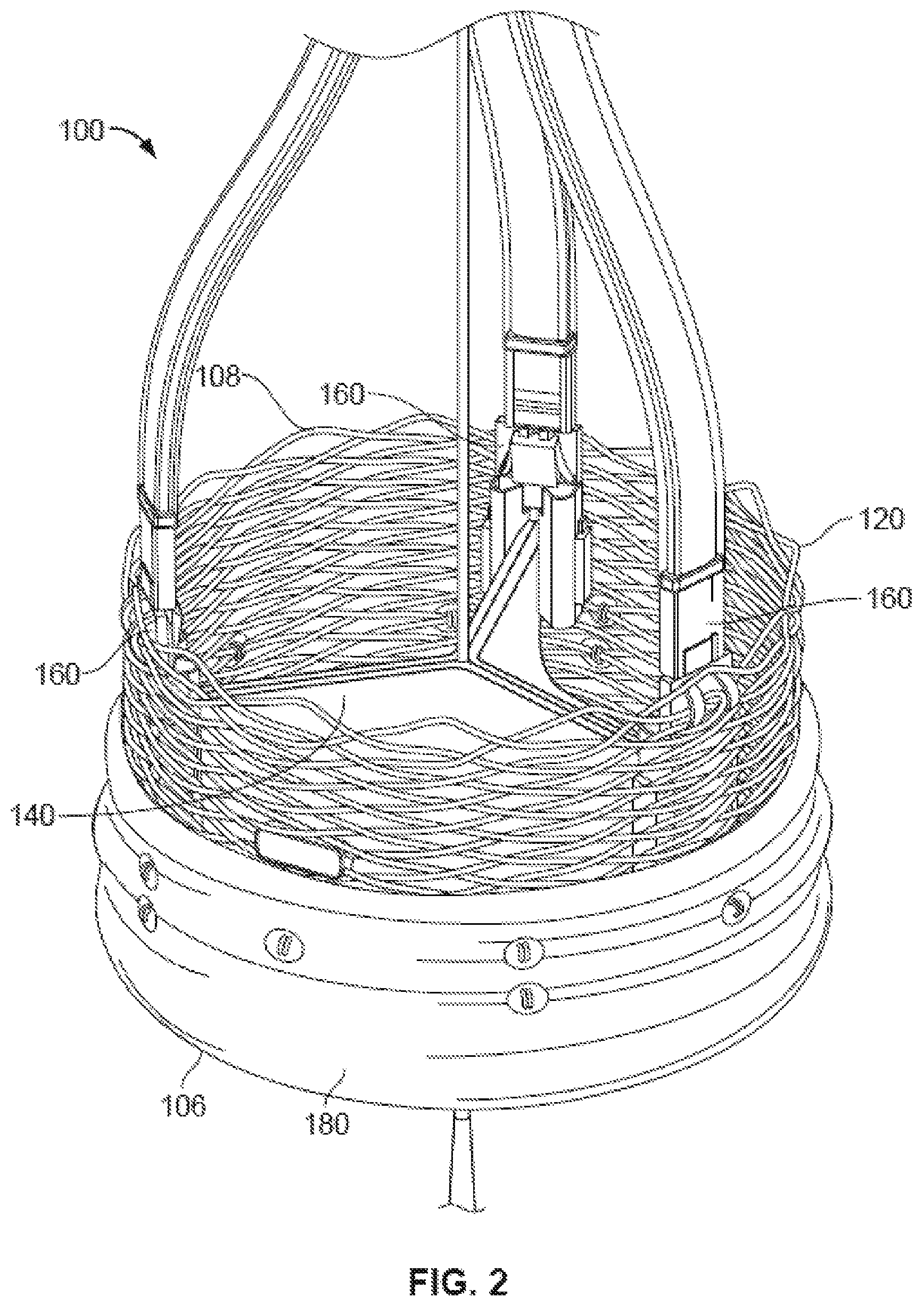
FIG. 2 is an enlarged view of the prosthetic heart valve of FIG. 1.
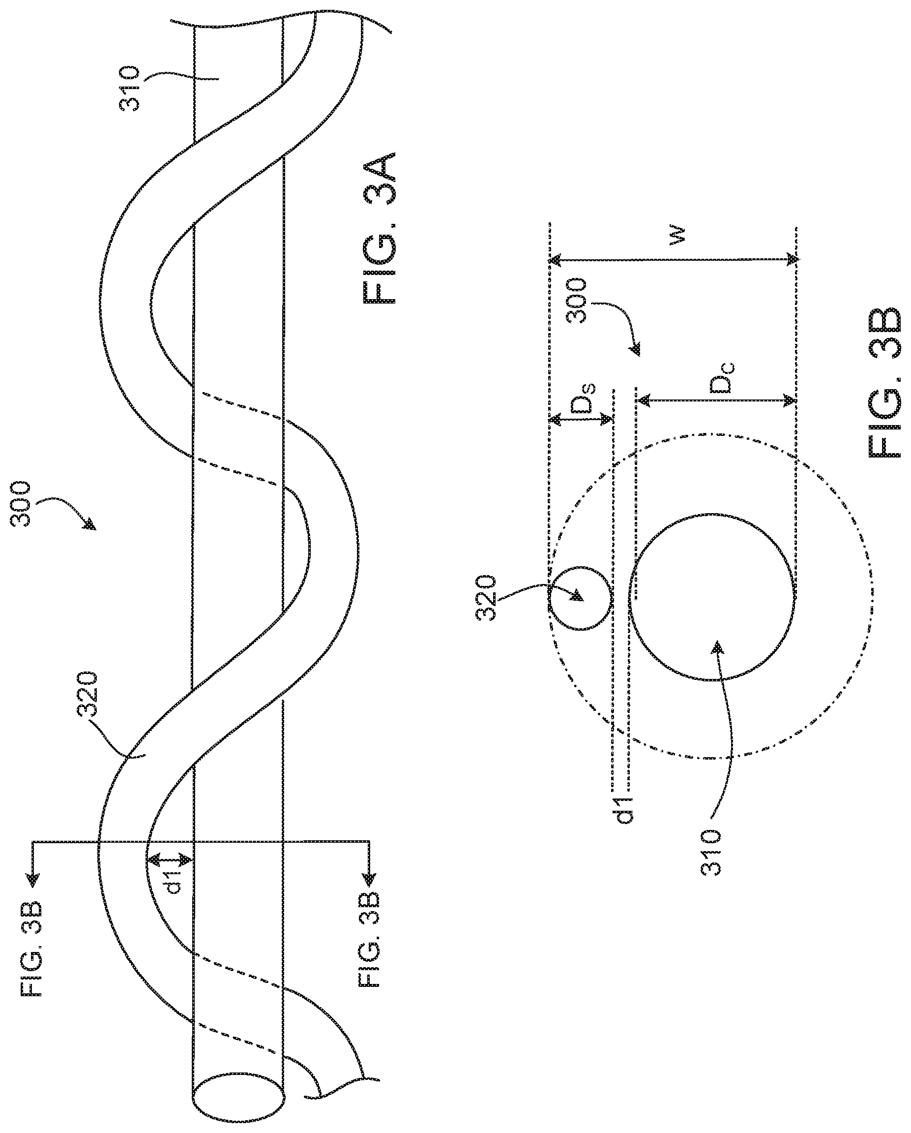
FIGS. 3A and 3B are views of an exemplary composite fiber provided herein. FIG. 3A provides a side perspective view of the composite fiber. FIG. 3B provides a cross-sectional view of the composite fiber of FIG. 3A.
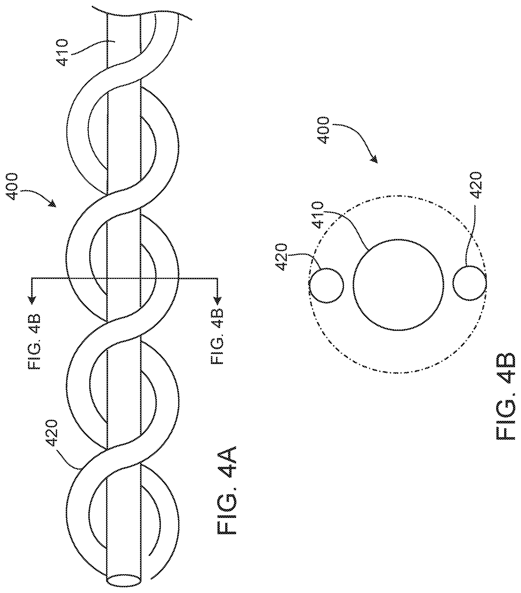
FIGS. 4A and 4B are views of another exemplary composite fiber provided herein. FIG. 4A provides a side perspective view of the composite fiber. FIG. 4B provides a cross-sectional view of the composite fiber of FIG. 4A.
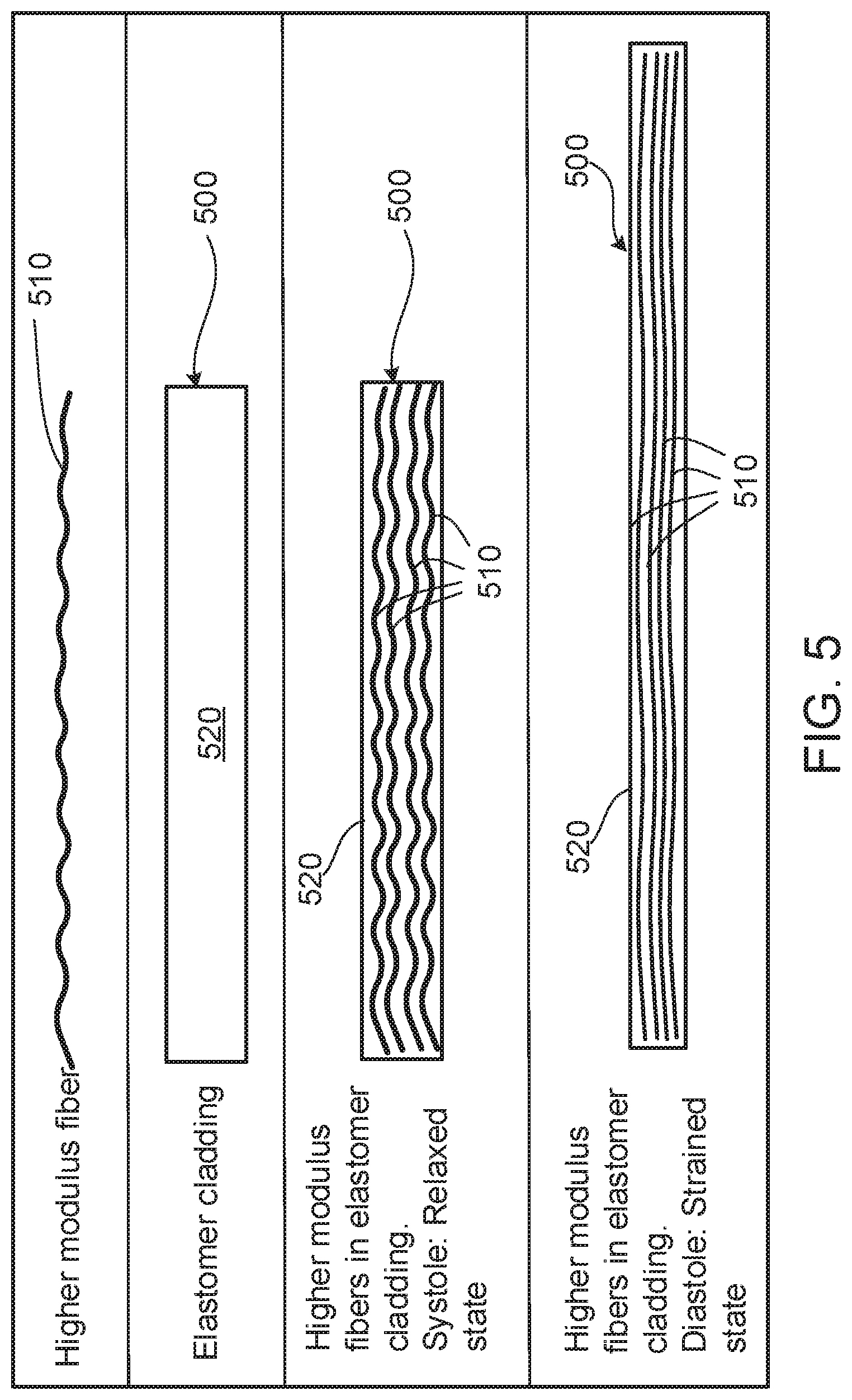
FIG. 5 provides schematic illustrations of another example of a composite fiber provided herein and components thereof.
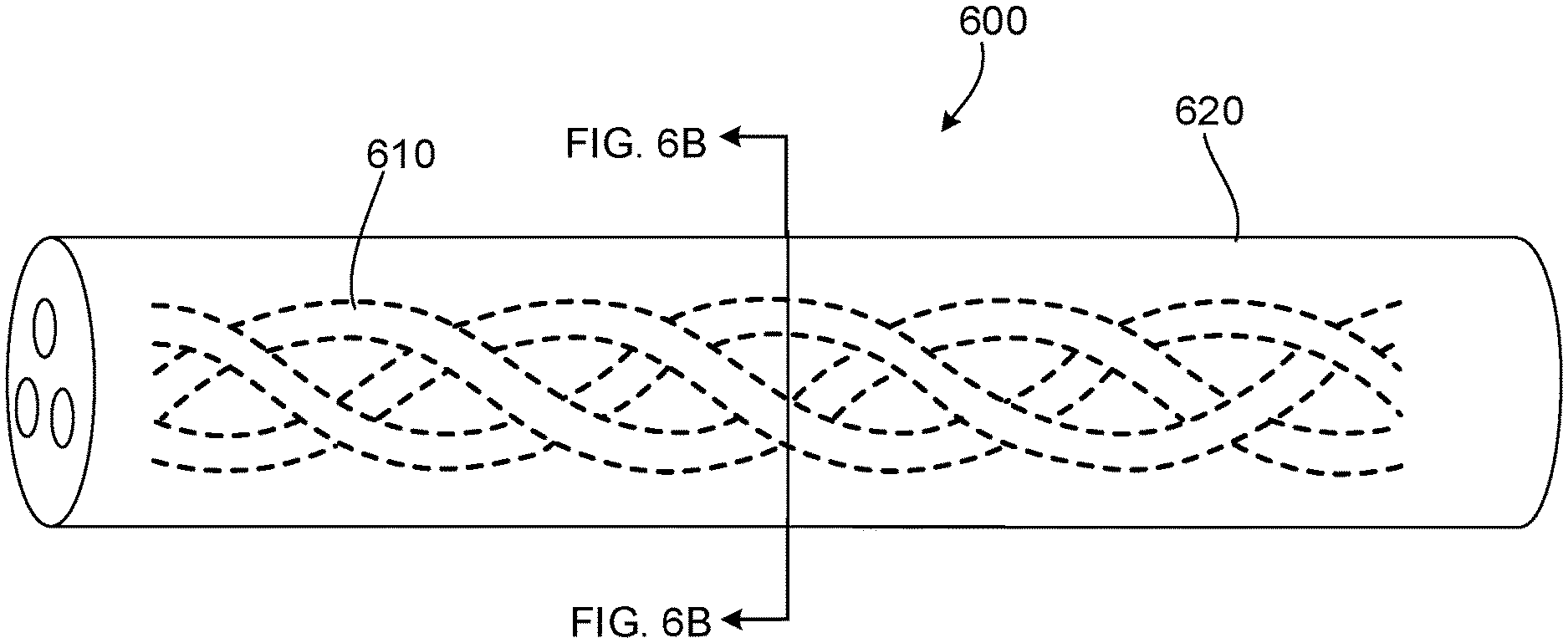
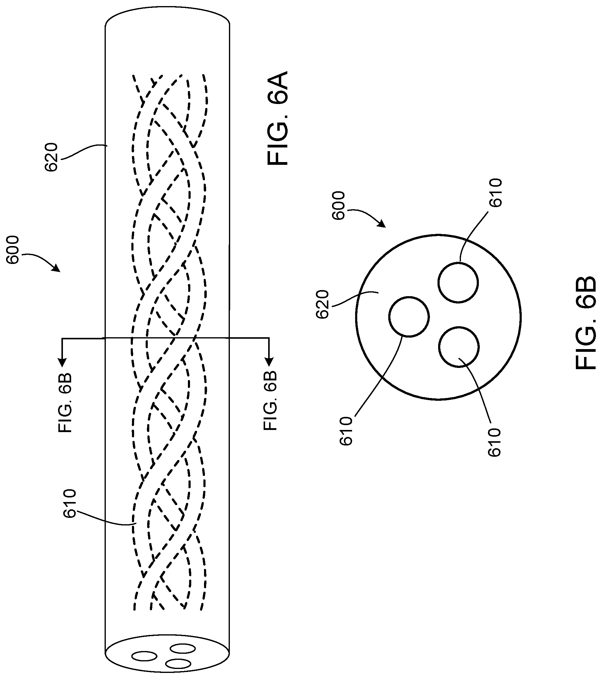
FIGS. 6A and 6B provide illustrations of another exemplary composite fiber provided herein and components thereof. FIG. 6A provides a perspective view of the composite fiber showing core fibers within the composite fiber. FIG. 6B provides a cross-sectional view of the composite fiber of FIG. 6A.
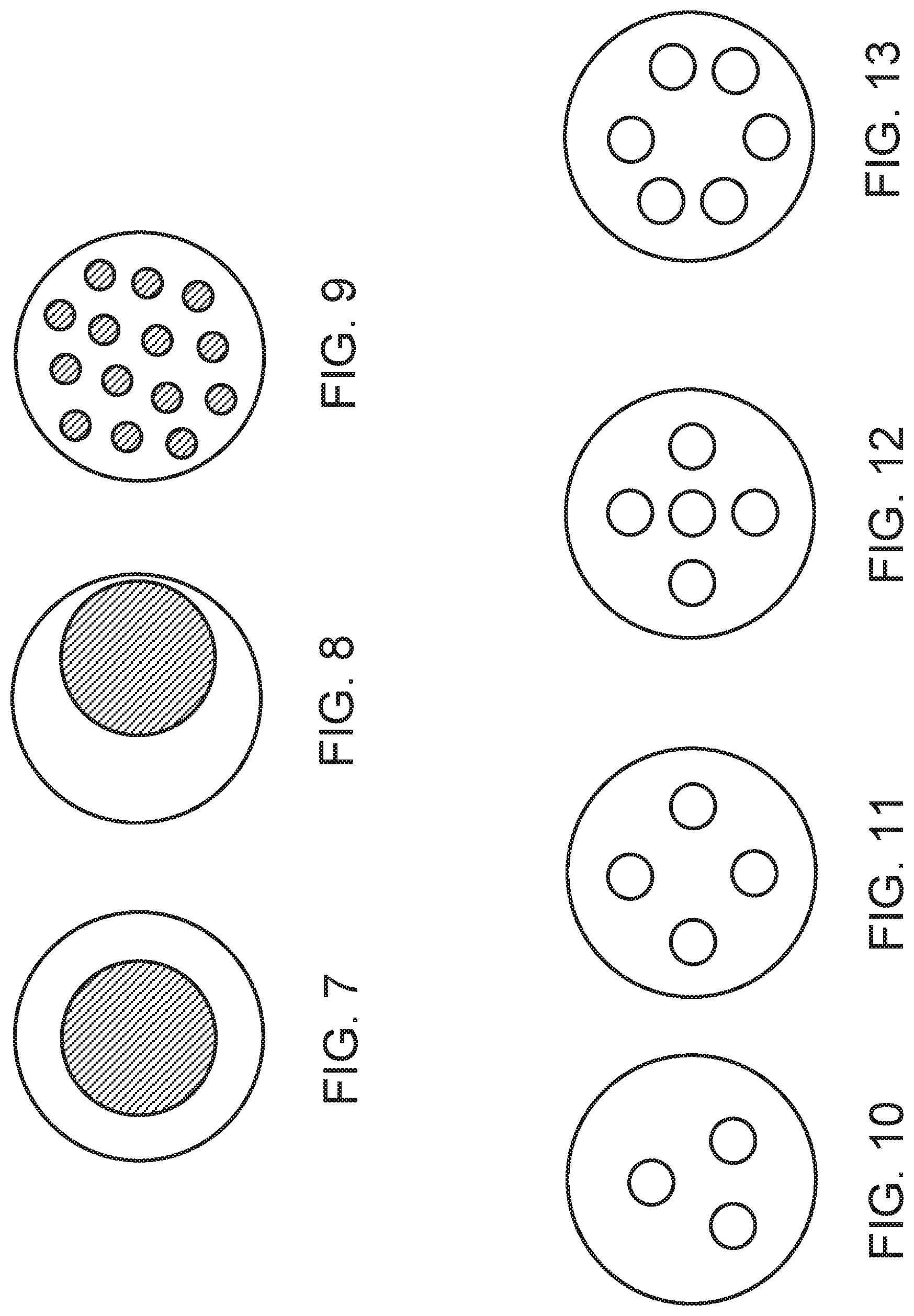
FIGS. 7-13 provide cross-sectional views of various exemplary composite fibers provided herein.
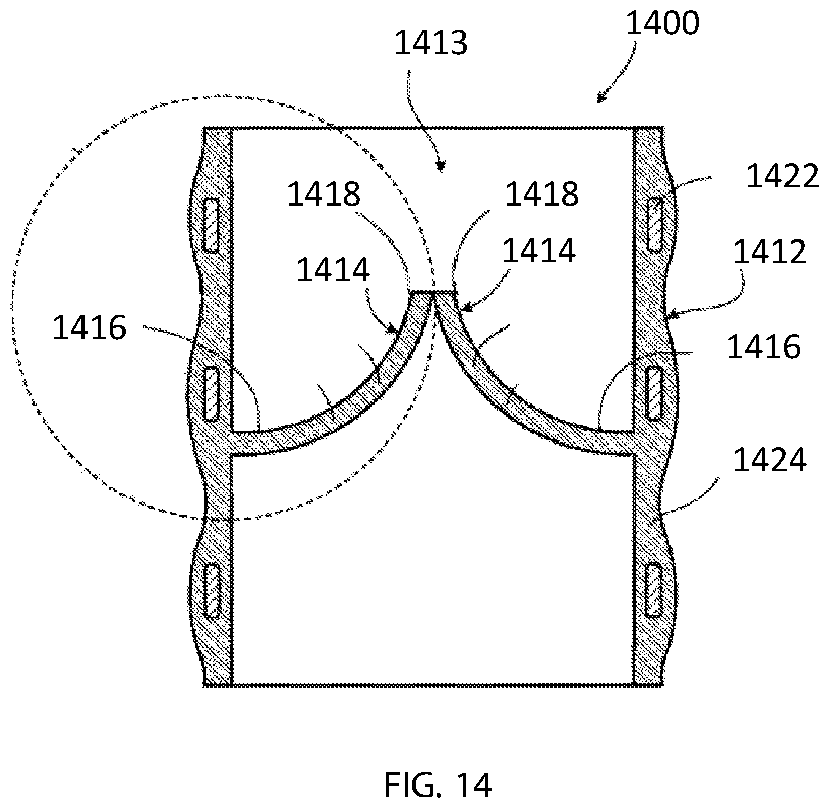
FIG. 14 is an illustration of another exemplary prosthetic heart valve provided herein.
DETAILED DESCRIPTION
FIG. 1 is an illustration of a prosthetic heart valve 100 provided herein within a heart 102 of a human body 105. The heart 102 has four heart valves: a pulmonary valve, a tricuspid valve, an aortic valve and a mitral valve. The heart valves allow blood to pass through the heart 102 and into major blood vessels connected to the heart 102, for example, the aorta and pulmonary artery. Prosthetic heart valve 100 of FIG. 1 is an aortic prosthetic heart valve that can be surgically implanted or delivered through blood vessels using a delivery device or catheter 110. The delivery catheter 110 can be inserted into a femoral, subclavian, or an aortic incision during a transcatheter aortic valve replacement (TAVR) procedure. Once inserted, the delivery catheter 110 can deliver the prosthetic heart valve 100 to a desired location within the anatomy and release the implantable heart valve 100 at a target implantation site. Although FIG. 1 shows prosthetic heart valve 100 replacing an aortic valve, in some cases, prosthetic heart valve 100 can be a replacement for another type of heart valve (e.g., a mitral valve or a tricuspid valve).
FIG. 2 provides a close up view of the prosthetic heart valve 100 and a distal end of the delivery catheter 110 of FIG. 1. The prosthetic heart valve 100 has a substantially tubular body 120, three leaflets 140, anchor elements 160 and a tubular seal 180. The tubular body 120 can be a radially expandable member, e.g. annular frame or stent, having an annular cavity. As shown in FIG. 2, the heart valve 100 can have a plurality of heart valve leaflets 140 coupled to the tubular body 120 within the annular cavity. Three anchor elements 160 positioned within the annular cavity of tubular body 120 can each secure the heart valve leaflets 140 to the tubular body 120. Each anchor element 160 can be coupled to the tubular body 120 with fasteners and coupled to the leaflets 140 with a clamping element. The tubular seal 180 can be disposed about a portion of the tubular body 120. In particular, the tubular seal 180 can have an outflow end portion 108 disposed about an outer surface of the tubular body 120 to restrict blood flow around the leaflets. The tubular seal 180 can also have an inflow end portion 106 secured to the bottom edges of the leaflets 140.
Prosthetic heart valve 100 can be made of various materials. In some cases, at least a portion of prosthetic heart valve 100, for example, the leaflets 140 or a portion of the tubular body 120, can be made of synthetic materials. In some cases, prosthetic heart valve 100 can be made entirely of synthetic materials. Suitable synthetic materials of prosthetic heart valve 100 can include, but are not limited to, polymeric materials, metals, ceramics, and combinations thereof. In some cases, synthetic materials of the prosthetic heart valve 100 can include a composite material composed of at least two constituent materials with different physical, mechanical and/or chemical properties. In some cases, synthetic materials of the prosthetic heart valve 100 provided herein can include a composite material composed of at least two constituent materials with different physical, mechanical and/or chemical properties
In use, the prosthetic heart valve 100 provided herein can be implanted either surgically or through transcatheter delivery into the heart 102. The edge portions of the leaflets 140 can move into coaptation with one another in a closed position to substantially restrict fluid from flowing past the closed prosthetic heart valve 100. The edge portions of the leaflets 140 can alternatively move away from one another to an open position permitting fluid to flow past the prosthetic heart valve 100. Movement of the leaflets 140 between the closed and open positions can substantially approximate the hemodynamic performance of a healthy natural valve.
As the prosthetic heart valve 100 opens and closes during each heartbeat, each leaflet 140 flexes between an open and a closed position. Tensile and flexural strain on the leaflet 140 can change depending on its position. Leaflets 140 can therefore elongate in various directions as the valve 100 opens and closes. Each leaflet 140 can elongate in a radial direction and/or a circumferential direction with each heartbeat. Leaflets 140 can also elongate in directions that are directed at an oblique angle relative to the radial and circumferential directions. Due to the various directions of elongation that a prosthetic leaflet 140 can experience during use, the leaflet 140 can greatly benefit by being composed of materials with anisotropic physical and mechanical properties, in some cases.
In various embodiments, a prosthetic heart valve 100 can be made from a fiber-reinforced composite material. In some cases, the fiber-reinforced composite material can be composed of a plurality of fibers and a polymer matrix. In some cases, the plurality of fibers can be randomly oriented or orderly aligned within the polymer matrix. In some cases, fibers of the fiber-reinforced composite material can include a plurality of composite fibers. Each composite fiber is composed of two or more different materials. The composite fiber can have various structural configurations, as will be discussed further in subsequent sections.
Heart valve leaflets 140 composed of composite fibers can provide several advantages. For example, a prosthetic heart composed of composite fibers can provide desirable mechanical performance of two or more materials. In some cases, composite fibers can have structural arrangements that provide the leaflets 140 with anisotropic mechanical properties. Composite fiber may, in some cases, form more durable synthetic materials that can be used for manufacturing heart leaflets for younger patients requiring long term durability devices. A prosthetic heart valve 100 made of composite fibers may provide a thinner heart valve material that has the desired mechanical strength, while allowing for the reduction of the valve profile of the device during delivery and access through smaller orifices, such as smaller femoral sheaths or smaller blood vessels. In some cases, heart valve leaflets 140 can be composed of biocompatible composite fibers that can reduce or eliminate calcification and deterioration of the leaflets 140. In some cases, prosthetic heart valves 100 made of composite fibers may reduce the need for long term anticoagulation therapy. The use of composite fibers, in some cases, may reduce the risk of sourcing issues and infection that might be associated with animal tissues, such as bovine spongiform encephalopathy.
FIGS. 3A and 3B show an example of a composite fiber 300 provided herein of a prosthetic heart valve leaflet, such as the prosthetic heart valve leaflet 140 of FIG. 2. The depicted composite fiber 300 includes a core fiber 310 (which can also be described as an inner fiber) and a sheathing fiber 320 (which can also be described as an outer fiber or a cladding fiber) disposed about the core fiber 310. As shown, the sheathing fiber 320 may be a single fiber wrapped spirally around the core fiber 310. In some cases, the composite fiber 300 can include a core fiber 310 and a sheathing fiber 320 disposed about the core fiber 310 for at least a portion of a length of the composite fiber 300, or over an entire length of the composite fiber 300.
The sheathing fiber 320 can be bonded to the core fiber 310 in at least at two separate bonding locations. In some cases, the sheathing fiber 320 can be bonded at first and second bonding locations along the core fiber 310 in which the first and second locations are separated by a predetermined bonding distance along a longitudinal axis defined by the core fiber 310. In some cases, the predetermined bonding distance between the first and second locations can range between 1 millimeters (mm) and 100 mm, including all values and ranges therebetween. In some cases, the predetermined bonding distance can range from about 1 mm to about 5 mm, about 5 mm to about 10 mm, about 10 mm to about 20 mm, about 20 mm to about 30 mm, about 30 mm to about 40 mm, about 40 mm to about 50 mm, about 50 mm to about 100 mm. By bonding the sheathing fiber 320 in at least two separate locations, the core fiber 310 is allowed to initially elongate relatively independent of the sheathing fiber 320. The elasticity of the core fiber 310 therefore dominates the elastic characteristic of the composite fiber 300 during initial stretching until the loose sheathing fiber 320 becomes tautly wrapped about the core fiber 310. The predetermined bonding distance can be adjusted as desired to increase or decrease the maximum strain and elasticity of the composite fiber 300. In some cases, the sheathing fiber 320 can be bonded to the core fiber 310 in more than two bonding locations. For example, the sheathing fiber 320 can be bonded to the core fiber 310 in two, three, four, five, or greater than five locations along the core fiber 310.
Still referring to FIGS. 3A and 3B, the sheathing fiber 320 can be wrapped loosely around the core fiber 310, forming a gap between the sheathing fiber 320 and the core fiber 310. In some cases, the gap can be defined by a radial distance "d1" between an exterior surface of the core fiber 310 and an adjacent, exterior surface of the core fiber 310. In some cases, a radial distance d1 of the gap can range from about 1 nm to about 1 micron, also including all values or ranges therebetween. At least a portion of the composite fiber 300 may optionally include no gap between the sheathing fiber 320 and the core fiber 310 (e.g., the radial distance is equal to 0). In some cases, the radial distance d1 can be characterized in terms of a diameter of the core fiber "Dc," for example, the radial distance d1 of the gap can range between 0 and 5 times the diameter of the core fiber Dc, for example, the radial distance d1 of the gap can be 0, 0.25, 0.50, 0.75, 1, 2, 3, 4, 5, or more than 5 times the diameter of the core fiber Dc.
As shown in FIG. 3B, transverse dimensions such as a radial width "w" of the composite fiber 300 can vary depending on the position of the sheathing fiber 320 relative to the core fiber 310. The radial width w of the composite fiber 300 is dependent on the diameter of the core Dc and a diameter of the sheathing fiber "Ds." For instance, in some cases, the radial width w of the composite fiber 300 can range between the diameter of the core fiber Dc up to approximately an additive sum of the core and sheathing fiber diameters (Dc+Ds). In some cases, a gap exists between the core fiber 310 and the sheathing fiber 320 that can increase the radial width w of the composite fiber 300.
The ratio of the diameter of the core fiber Dc and the sheathing fiber diameter Ds, in some cases, can range from about 1:1 to about 10:1, in addition to all values and ranges therebetween. In some cases, the ratio of the core and sheathing fiber diameters (Dc:Ds) can range from about 1:10 to about 1:5, about 1:5 to about 1:4, about 1:4 to about 1:3, about 1:3 to about 1:2, about 1:2 to about 1:1, about 1:1 to about 2:1, from about 2:1 to about 3:1, from about 3:1 to about 4:1, from about 4:1 to about 5:1, about 5:1 to 10:1, from 1:10 to 10:1, from 1:5 to 5:1, from 1:4 to 4:1, from 1:3 to 3:1, from 1:2 to 2:1, from 1:10 to 5:1, from 1:10 to 4:1, 1:10 to 3:1, from 1:10 to 2:1, from 1:10 to 1:1, from 1:1 to 1:10, from 1:2 to 1:10, from 1:3 to 1:10, from 1:4 to 1:10, from 1:5 to 1:10, from 1:6 to 1:10, from 1:7 to 1:10, from 1:8 to 1:10, or from 1:9 to 1:10. The ratio of core and sheathing fibers diameters can allow the mechanical properties (e.g., elastic properties) of the composite fiber 300 to be adjusted as desired.
Composite fibers 300 can be composed of core fibers 310 and/or sheathing fibers 320 having diameters or average diameters of at least 1 micron (or 0.00004 inches). Core fibers 310 and/or sheathing fibers 320 can be, in some cases, in the range of about 1 micron to about 100 microns (or about 0.00004 inches to about 0.004 inches), including all ranges and values therebetween. In some cases, for example, suitable core fibers 310 and/or sheathing fibers 320 diameter sizes can include ranges of about 1 micron to 5 microns (or about 0.00004 inches to about 0.0002 inches), 5 microns to 10 microns (or 0.0002 inches to about 0.0004 inches), 10 microns to 20 microns (or 0.0004 inches to about 0.0008 inches), 20 microns to 50 microns (or 0.0008 inches to about 0.0020 inches), and 50 microns to 100 microns (or 0.002 inches to about 0.004 inches). In some cases, core fibers 310 and/or sheathing fibers 320 can have diameters in the range of about 1 microns to about 10 microns (or 0.0004 inches to about 0.0020 inches), including all ranges and values therebetween. In some cases, the core fibers 310 and/or sheathing fibers 320 made from polymers can range from about 5 microns to about 100 microns (or 0.00002 inches to about 0.0040 inches), from about 10 microns to about 75 microns (or 0.0004 inches to about 0.003 inches), from about 10 micron to about 50 microns (or 0.0004 inches to about 0.0020 inches), from about 20 microns to about 100 microns (or 0.0008 inches to about 0.0040 inches), from about 25 microns to about 200 microns (or 0.001 inches to about 0.008 inches), or from about 20 microns to about 50 microns (or 0.0008 inches to about 0.002 inches). In some cases, core fibers 310 and/or sheathing fibers 320, such as LCP fibers, can range from 0.5 microns (or 500 nanometers) to 5 microns (or about 0.00002 inches to about 0.00020 inches).
In some cases, composite fibers 300 can include core fibers 310 and/or sheathing fibers 320 having diameters or average diameters less than 1 micron, or 1000 nanometers (nm) (or 0.00004 inches). In some cases, core fibers and/or sheathing fibers diameters or average diameters can range from 1 nm to 1000 nm, including all ranges and values therebetween. For example, core fibers and/or sheathing fibers diameters can range from about 1 nm to 10 nm, 10 nm to 50 nm, 50 nm to 100 nm, 100 nm to 500 nm, and 500 nm to 1000 nm. In some cases, fiber diameters can range from 100 nm to 1000 nm, including all ranges and values therebetween. Core fibers and/or sheathing fibers diameter can significantly affect physical and/or mechanical properties of a composite material. In some cases, a core fiber and/or sheathing fiber diameter can be sized to obtain a composite fiber 300 having desired physical and/or mechanical properties of two or more materials. For example, increasing the core fibers and/or sheathing fibers diameter of an exemplary composite material can, in some cases, increase the tensile strength of the material.
Fiber-reinforced composite materials provided herein can be composed of composite fibers 300 that are aligned in an orderly pattern to form a woven fibrous structure. In some cases, composite fibers 300 of fiber-reinforced composite materials can be composed of individual composite fibers 300 randomly oriented within a polymer matrix to form a non-woven, fibrous structure. In some cases, fiber-reinforced composite materials are composed of electrospun, composite fibers 300. A non-woven, fibrous structure can provide an isotropic material that have the same mechanical properties in all directions while a woven, fibrous structure can produce an anisotropic material that has directionally dependent mechanical properties.
Fiber-reinforced composite materials provided herein can optionally include a polymer matrix embedded within and/or covering over a fibrous structure composed of composite fibers 300. In some cases, the polymer matrix can interpenetrate the fibrous structure such that at least a portion of the polymer matrix become disposed between voids or spaces formed between individual composite fibers 300 of the fibrous structure.
Fiber-reinforced composite materials can include composite fibers 300 embedded within a polymer matrix in at least one layer (or section) of the fiber-reinforced material, or throughout the entire fiber-reinforced material. In some cases, the fiber-reinforced composite material can be composed of a plurality of composite fibers 300 and the polymer matrix. In some cases, some portions of the fiber-reinforced composite material can contain composite fibers 300 and some portions of the fiber-reinforced composite material can include no composite fibers 300. In some cases, some portions of the fiber-reinforced composite material can contain the polymer matrix and some portions of the fiber-reinforced composite material can include no polymer matrix. In some cases, the fiber-reinforced composite material can include additional layers of polymer, which can include different polymers than the polymer in polymer matrix or the same polymer in the polymer matrix. In some cases, different layers of polymer can include different polymer fibers, such as non-composite fibers (e.g., a fiber made of a single polymer) or different composite fibers 300, and/or different fiber arrangements. In some cases, the fiber-reinforced composite material can have an arrangement of composite fibers 300 within the matrix that results in producing isotropic properties. In some cases, a heart leaflet can include a fiber-reinforced composite material composed of a plurality of fibers and polymer matrix throughout the entire leaflet to simplify manufacturing.
In some cases, a layer of composite fibers 300 can be formed within a fiber-reinforced composite material. In some cases, a single layer of composite fibers 300 can include more than one material. In some cases, the fiber-reinforced composite material can include multiple layers of composite fibers 300, for example, two, three, four, five or greater than five layers of composite fibers 300. In some cases, at least one layer of composite fibers 300 can be made of the same material, for example, a first polymer. In some cases, the different layers of composite fibers 300 can be made from different materials, e.g., a first layer can be made from a first polymer and a second layer can be made from a second polymer. Having more than one layer may minimize or prevent tearing and other material-related failures of a heart valve leaflet.
In some cases, the exemplary fiber-reinforced composite material provided herein can include a layer of composite fibers 300 adjacent a solid, polymeric layer that does not contain fibers, e.g., a polymer film or coating. For instance, in some cases, an exemplary fiber-reinforced composite material provided herein can include a polymer film disposed over a plurality of composite fibers 300 or a layer of composite fibers 300.
FIGS. 4A and 4B show another example of a composite fiber 400 provided herein. The composite fiber 400 includes a core fiber 410 and two sheathing fibers 420 disposed about the core fiber 410. The depicted sheathing fibers 420 can be spirally wrapped around the core fiber 410, in some cases. In some cases, features provided herein for the composite fiber 300 of FIG. 3 can also apply to the composite fiber 400.
A composite fiber 400 provided herein may include two, three, four, five, or more than five sheathing fibers 420 spirally disposed about a core fiber 410. In some cases, at least two or more sheathing fibers 420 can be spirally disposed about each other in addition to being spirally disposed about the core fiber 410.
FIG. 5 shows another example of a composite fiber 500 provided herein. The depicted composite fiber 500 includes multiple core fibers 510 encapsulated within a sheathing fiber 520. Each core fiber 510 can be encapsulated within the sheathing fiber 520 (e.g., an elastomeric sheathing fiber) such that each core fiber 510 has a non-linear shape when the composite fiber 500 is in a relaxed (non-stretched) state. In some cases, the non-linear shape of the core fiber 510 can include an undulating shape with respect to a longitudinal axis defined by the composite fiber 500. Each core fiber 510 can change to a linear (i.e., straight) shape within the sheathing fiber 520 when the composite fiber 500 is stretched out. In some cases, each composite fiber 500 can include only one core fiber 510 having an undulating form within a sheathing fiber 520. In some cases, the composite fiber 500 can have two, three, four, five, six or more than six undulating core fibers 510 within the sheathing fiber 520.
FIGS. 6A and 6B show another example of a composite fiber 600 provided herein. The depicted composite fiber 600 includes three core fibers 610 encapsulated within a sheathing fiber 620, e.g., an elastomeric sheathing fiber. The core fibers 610 of the depicted composite fiber 600 are helically disposed about a longitudinal axis of the composite fibers 600, forming a triple helix shape within the sheathing fiber 620.
FIGS. 7-13 show cross-sectional views of various composite fibers provided herein. FIGS. 7 and 8 provide examples of a composite fiber having a single core fiber and encapsulated within a sheathing fiber. In FIG. 7, the core fiber is concentrically positioned within the sheathing fiber. In FIG. 8, the core fiber is off-center (i.e., non-concentric) with respect to the sheathing fiber. FIGS. 9-13 provide examples of composite fibers that include a plurality of core fibers encapsulated within a sheathing fiber. An exemplary composite fiber can include, but is not limited to, two core fibers, three core fibers, four core fibers, five core fibers, six core fibers, seven core fibers, eight core fibers, nine core fibers, ten core fibers, eleven core fibers, twelve core fibers, thirteen core fibers, fourteen core fibers, or more than fourteen core fibers within a sheathing fiber. In some cases, a composite fiber can include one or more central core fibers, for example, core fibers of FIGS. 9 and 12. In some cases, a composite fiber can include non-central core fibers, for example, core fibers of FIGS. 10, 11 and 13. In some cases, a core fiber can be disposed about one or more other core fibers. For example, one or more core fibers may be disposed spirally about a central core fiber.
Composite fibers provided herein can include a sheathing fiber that has been surface modified to provide desired surface characteristics. In some cases, the surface modification can include applying a coating of polyethylene glycol over the composite fiber.
The composite fiber provided herein can be made of various materials that include polymers, ceramics, and metals. In some cases, the core fiber or sheathing fiber is made of a polymer, such as a thermoplastic, a thermoset, or an elastomeric material. In some cases, the core and/or sheathing fibers can be made of a polymer having ceramic or metallic nanofibers, fillers, and/or particulates. The core fiber and the sheathing fiber(s) can be made of different materials to achieve a composite fiber having mechanical properties that are characteristic of two or more materials. In some cases, the material of the core fiber has a higher modulus than the material of the sheathing fiber. In some cases, the material of the core fiber has a lower modulus than the material of the sheathing fiber. In some cases, at least a portion of the core fiber and at least a portion of the sheathing fiber can optionally be made of the same or similar materials.
Composite fibers of the leaflets described herein can be made of various materials suitable for medical devices and/or implants. The composite fibers can be made of various biostable and/or biocompatible materials. A biostable material is a material that is resistant to degradation over a predetermined time period, e.g., 5 years, 10 years, 15 years, 20 years, or a time period equal to a use life of a medical device. A biocompatible material is a synthetic or natural material that is not harmful to living tissue. In general, fibers described herein can be composed of polymers, metals (e.g., titanium, stainless steel, tantalum), ceramics (fiberglass, acrylics), or combinations thereof. In some cases, fibers are made of thermoplastic polymers, thermoset polymers or combinations thereof. Fibers provided herein can be made of various polymeric materials, such as fluoropolymers, polyurethanes or block copolymers. Suitable polymers for fibers provided herein can be formed from fluoropolymers including, but not limited to, for example, polytetrafluoroethylene (PTFE), polyvinylidene fluoride (PVDF) (e.g. Kynar.TM. and Solef.TM.), poly(vinylidene fluoride-co-hexafluoropropene) (PVDF-HFP) and combinations thereof. Other suitable fiber polymers can include urethane-based polymers such as polyurethanes, polyurethane elastomers (e.g. Pellethane), polyether-based polyurethanes (e.g. Tecothane), polycarbonate-based polyurethanes (e.g. Bionate and Chronoflex) and combinations thereof. In some cases, other examples of suitable polymer materials for fibers include, but are not limited to, polycarbonates, polyethers, polyesters such as polyethylene terephthalate (PET), polyethylenes, polypropylenes, polyamides (e.g., Kelvar.RTM., Pebax.RTM., nylon 6 and nylon 12), polyetheretherketones (PEEK), polysulfones, polyvinyl alcohols, polyetherimides, polyimide (PI), polybenoxazole (PBO), polybenzothiazole (PBT), polybenzimidazole (PBI), poly-N-phenylbenzimidazole (PPBI), polyphenylquinoxaline (PPG), poly(p-phenylene terephthalamide) (PPTA), polysulfone, naphtalate based polymer fibers such as polybuthylenenaphtalate (PBN) and polyethylenenaphtalate (PEN), polyhydroquinone-diimidazopyridine (PIPD or also known as M5 fibers) and combinations thereof. In some cases, fibers are formed from block copolymers such as, for example, a poly(styrene-isobutylene-styrene) (SIBS) tri-block polymer and a polyisobutylene urethane copolymer (PIB-PUR).
In some cases, polyisobutylene urethane copolymers (PIB-PUR) can be used to form composite fibers provided herein. PIB-PUR is composed of soft segment portions and hard segment portions. Polyurethane hard segment portions can include, but are not limited to, methylene diphenyl diisocyanate (MDI), 4,4'-Methylene dicyclohexyl diisocyanate (H12MDI) and hexamethylene (HMDI). Polyurethane soft segment portions can include polyisobutylene macrodiol or polyisobutylene diamine. In some cases, suitable soft segments can include linear, branched or cyclic forms of polyalkene, polyether, a fluorinated polyether, a fluoropolymer, a polyester such as polyethylene terephthalate (PET), a polyacrylate, a polymethacrylate, a polysiloxane, a fluorinated polysiloxane, or a polycarbonate and derivatives thereof. PIB-PUR and PIB-PUR derivatives have the advantages of providing an inert, biocompatible, non-thromobogenic and anti-calcifying material for medical devices and implants.
Composite fibers of the composite material of a leaflet can, in some cases, be made of a liquid crystalline polymer (LCP). LCPs are a special class of aromatic polyester or polyamide copolymers that have semi-crystalline properties due to regions of highly ordered crystalline structures formed therein. LCPs are materials that are generally chemically inert and have a high creep resistance, a high modulus and a high tensile strength. Suitable fiber materials made of LCPs include, but are not limited to, thermotropic polyesters such as poly(p-phenylene terephthalamide) (PPTA), poly(phenylene benzobisoxazole) (PBO), and combinations thereof. Other suitable LCPs can include poly(p-phenylene terephthalamide), such as Kevlar.RTM., Vectran.RTM., Poly(m-phenylene isophthalamide) such as Nomex.RTM. and Teijinconex.RTM., Herachron.RTM., Technora.RTM., Twaron.RTM., and Zylon.RTM.. In some cases, other high performance fibers can utilized, such as gel-spun ultra-high molecular weight polyethylene (Dyneema.RTM. and Spectra.RTM.). Benefits of using LCPs include providing leaflets with optionally thinner and smaller dimensions, e.g., thickness or diameter, without compromising mechanical properties of the leaflet, such as tensile strength, or performance characteristics such as robustness and durability. In some cases, diameters of composite fibers made of LCPs can be as small as 0.5 micrometers (or .mu.m). In some cases, thicknesses of a leaflet composed of composite fibers made of LCPs can range from about 50 .mu.m to about 100 .mu.m.
The composite fibers and/or the polymer matrix of the fiber-reinforced composite material can be made of various biostable and/or biocompatible polymeric materials. In some cases, the polymer matrix can be made of a thermoplastic, thermoset, or an elastomeric polymer. Suitable polymer matrix materials can include, but are not limited to, homopolymers, copolymers and terpolymers. Various polyurethanes can be used to construct the polymer matrix, such as polyurethanes with soft segments such as polyether, perfluoropolyether, polycarbonate, polyisobutylene, polysiloxane, or combinations thereof.
In some cases, the composite fibers and/or polymer matrix of the fiber-reinforced composite material can be formed from block polymers such as, for example, poly(styrene-isobutylene-styrene) (SIBS) tri-block polymers. Other suitable elastomeric materials include, but are not limited to, silicones, nitrile rubber, fluoroelastomers, polyolephin elastomers, latex-type elastomers, various natural elastomers such as those made from collagen, elastin, cellulose, proteins, carbohydrates, and combinations thereof.
In some cases, individual composite fibers can be encapsulated within a jacket (e.g., a polymer jacket) to promote bonding between the composite fibers and a polymer matrix material.
The core fiber or sheathing fibers of the composite fibers provided herein, in some cases, can include fillers to form composite fibers to increase the tensile strength of the composite fibers. Suitable fillers can include, but are not limited to, carbon nano-sized tubes, ceramic fillers such as talc, calcium carbonate, mica, wollastonite, dolomite, glass fibers, boron fibers, carbon fibers, carbon blacks, pigments such as titanium dioxide, or mixtures thereof. The amount of filler included in the core fiber or sheathing fibers of the composite fibers provided herein may vary from about 0 wt % to about 20 wt % of the combined weight of fiber polymer and filler. Generally amounts from about 5 wt % to about 15 wt % and from about 0 wt % to about 4 wt %, may be included. In some cases, the core fiber or sheathing fibers of the composite fibers provided herein contain less than 1 wt % by weight filler and are substantially free of fillers.
Composite fiber density, such as fiber weight percent, within a composite material can vary. In some cases, weight percent of composite fibers within a fiber-reinforced composite material can generally range from about 0.1 wt % to about 50 wt %, including all ranges and values therebetween. In some cases, for example, the fiber weight percentage can range from 0.1 to 0.5 wt %, 0.5 to 1 wt %, 1 to 2 wt %, 2 to 3 wt %, 3 to 4 wt %, 4 to 5 wt %, 5 to 10 wt %, 10 to 20 wt %, 20 to 30 wt %, 30 to 50 wt %, 0.5 to 30 wt %, 1 to 20 wt %, 2 to 10 wt %, or 3 to 5 wt %. In some cases, the fiber weight percentage of a composite material can range from about 1 wt % to about 5 wt %. The fiber weight percentage can significantly affect physical and/or mechanical properties of a composite material. In some cases, a suitable fiber weight percentage can be used to customize or adjust the physical and/or mechanical properties of a leaflet material.
Although the prosthetic heart valves provided herein are generally made of synthetic materials, such as materials made of composite fibers, in some cases, prosthetic heart valves can be made of both synthetic materials and non-synthetic materials such as mammalian tissue (e.g., porcine or bovine tissue). For example, in some cases, at least a portion of a leaflet provided herein can be made from composite fibers provided herein as well as tissue obtained from an animal, e.g., bovine pericardium or porcine tissue.
FIG. 14 provides another embodiment of a prosthetic heart valve 1400. Prosthetic heart valve 1400 includes a base 1412 defining a substantially cylindrical passage 1413 and a plurality of polymeric leaflets 1414 disposed along the substantially cylindrical passage 1413. Each polymeric leaflet 1414 includes a respective root portion 1416 coupled to base 1412 and a respective edge portion 1418 movable relative to the root portion 1416 to coapt with the edge portions of the other polymeric leaflets along a coaptation region. In some cases, the entire heart valve 1400 can be made of a fiber-reinforced composite material provided herein. In some cases, portions of heart valve 1400, e.g., the polymeric leaflets 1414 of the heart valve 1400, can be made of a fiber-reinforced composite material provided herein. In some cases, the polymeric leaflets 1414 can include a plurality of composite fibers provided herein.
Base 1412 includes a frame 1422 disposed in a polymer layer 1424. The polymer layer 1424 can be composed of fiber-reinforced composite materials provided herein. In some cases, polymer layer 1424 can include a plurality of composite fibers 1414 provided herein. Polymer layer 1424 secures respective root portions 1416 of polymeric leaflets 1414 to the base 1412. Polymer layer 1424 can form a substantially continuous surface with respective root portions 1416 of polymeric leaflets 1414. This can reduce the likelihood of stress concentrations at the junction of respective root portions 1416 and base 1412. Additionally or alternatively, polymer layer 1424 can be disposed between each of polymeric leaflets 1414 and frame 1422 such that polymer layer 1424 protects polymeric leaflets 1414 from inadvertent contact with frame 1422 (e.g., as can occur through eccentric deformation of prosthetic heart valve 1400 on a calcium deposit present at the implantation site).
In some cases, frame 1422 is substantially cylindrical such that the outer surface of the base 1412 is substantially cylindrical and the polymer layer 1424 disposed on the frame 1422 forms the substantially cylindrical passage 1413. In some cases, frame 1422 is completely disposed in the polymer layer 1424, with the polymer layer 1424 forming a contoured outer surface of the valve 1400. In some cases, the frame 1422 is partially disposed in the polymer layer 1424. In some cases, the polymer layer 1424 is applied to the frame 1422 to form a substantially smooth inner and/or outer surface of the valve 1400.
Methods of Forming Composite Fibers
Various methods can be applied when forming composite fibers provided herein. In some cases, electrospinning can be used to form the core fiber and/or the sheathing fiber of the composite fiber. Suitable methods for forming at least a portion of the composite fibers include, but are not limited to, compression molding, extrusion, solvent casting, injection molding, force spinning, melt-blowing, and combinations thereof. Examples of other methods for partially or fully constructing a part composed of a composite material also include, but are not limited to, dip coating, roll coating, spray coating, flow coating, electrostatic spraying, plasma spraying, spin coating, curtain coating, silkscreen coating, and combinations thereof. In some cases, the processes described herein can be used to form composite fibers and/or a polymer matrix of a fiber-reinforced composite material.
In some cases, the core fibers and the sheathing fibers are constructed simultaneously. In some cases, the core fibers and the sheathing fibers of the core are constructed separately. In the latter case, the sheathing fibers can be disposed about the core fiber(s) and then subjected to a bonding process, which will be discussed later in further detail.
Polymer fibers (e.g., nanofibers) can be generated, in some cases, through combining a template method with an extrusion process. In this process, polymer fibers can be formed when molten polymer is forced through pores of an anodic aluminum membrane and cooled thereafter. In a subsequent process, a sheathing fiber(s) can be disposed about a core fiber by wrapping or braiding one or more polymer fibers around the core fiber. In some cases, wrapping or braiding can be achieved by using an electrospinning process or, in the case of a more complex braid involving multiple sheathing fibers, with a braiding equipment capable of mechanically wrapping or braiding fibers.
An elastomer sheathing fiber can be formed, in some cases, by forming a first elastomeric layer, depositing core fibers configured with an undulating form on the first elastomeric layer, and adding a second elastomeric layer over the core fibers. The fibers can be encapsulated within the sheathing fiber by adding the second elastomeric layer. In some cases, core fibers can be pre-formed and inserted into a mold or extruder that injects a sheathing material around the core fibers.
Various bonding processes can be used to bond the core fiber(s) and the sheathing fiber(s) together. In some cases, the core and sheathing fibers can be bonded together by a corona discharge exposure. In some cases, either the core or the sheathing fibers can be melted to facilitate bonding between the core and sheathing fibers. Adhesive bonding can also be used to providing bonding between the core and sheathing fibers, in some cases.
Composite fibers provided herein can include surface modifying the core and/or sheathing fibers to provide desired surface characteristics. In some cases, surface modification can include plasma treatment. In some cases, surface modification includes adding a coating to an exterior surface of the core and/or sheathing fibers. In some cases, a polymer coating can be applying to exterior surfaces of the composite fibers using one of many types of applications. Suitable coating applications can include, but are not limited to, dip and spray coating processes.
In some cases, an exemplary method of forming a prosthetic heart valve material can include disposing one or more layers composed of composite fibers using one or more of the processes provided herein.
* * * * *
References
D00000
D00001
D00002
D00003
D00004
D00005
D00006
D00007
D00008
XML
uspto.report is an independent third-party trademark research tool that is not affiliated, endorsed, or sponsored by the United States Patent and Trademark Office (USPTO) or any other governmental organization. The information provided by uspto.report is based on publicly available data at the time of writing and is intended for informational purposes only.
While we strive to provide accurate and up-to-date information, we do not guarantee the accuracy, completeness, reliability, or suitability of the information displayed on this site. The use of this site is at your own risk. Any reliance you place on such information is therefore strictly at your own risk.
All official trademark data, including owner information, should be verified by visiting the official USPTO website at www.uspto.gov. This site is not intended to replace professional legal advice and should not be used as a substitute for consulting with a legal professional who is knowledgeable about trademark law.