End user device that secures an association of application to service policy with an application certificate check
Raleigh , et al.
U.S. patent number 10,716,006 [Application Number 15/976,170] was granted by the patent office on 2020-07-14 for end user device that secures an association of application to service policy with an application certificate check. This patent grant is currently assigned to Headwater Research LLC. The grantee listed for this patent is Headwater Research LLC. Invention is credited to Jeffrey Green, James Lavine, Gregory G. Raleigh.


View All Diagrams
| United States Patent | 10,716,006 |
| Raleigh , et al. | July 14, 2020 |
End user device that secures an association of application to service policy with an application certificate check
Abstract
Network service provisioning is described. Network service provisioning to a device includes a mechanism for ensuring that network services are available based upon one or more of appropriate traffic control, billing, and notification policies. Ensuring that the policies are properly enforced on a device is a focus of this paper. The enforcement policies can be on the device or in the network.
| Inventors: | Raleigh; Gregory G. (Woodside, CA), Lavine; James (Corte Madera, CA), Green; Jeffrey (Sunnyvale, CA) | ||||||||||
|---|---|---|---|---|---|---|---|---|---|---|---|
| Applicant: |
|
||||||||||
| Assignee: | Headwater Research LLC (Tyler,
TX) |
||||||||||
| Family ID: | 53174661 | ||||||||||
| Appl. No.: | 15/976,170 | ||||||||||
| Filed: | May 10, 2018 |
Prior Publication Data
| Document Identifier | Publication Date | |
|---|---|---|
| US 20190132736 A1 | May 2, 2019 | |
Related U.S. Patent Documents
| Application Number | Filing Date | Patent Number | Issue Date | ||
|---|---|---|---|---|---|
| 15160520 | May 20, 2016 | 9973930 | |||
| 14541493 | Nov 14, 2014 | 9392462 | |||
| 13309556 | Dec 1, 2011 | 8893009 | |||
| 13134028 | May 25, 2011 | 8589541 | |||
| 13134005 | May 25, 2011 | 8635335 | |||
| 12695021 | Jan 27, 2010 | 8346225 | |||
| 12380780 | Mar 2, 2009 | 8839388 | |||
| 12380778 | Mar 2, 2009 | 8321526 | |||
| 12380780 | Mar 2, 2009 | 8839388 | |||
| 61472606 | Apr 6, 2011 | ||||
| 61435564 | Jan 24, 2011 | ||||
| 61422565 | Dec 13, 2010 | ||||
| 61422574 | Dec 13, 2010 | ||||
| 61422572 | Dec 13, 2010 | ||||
| 61420727 | Dec 7, 2010 | ||||
| 61418507 | Dec 1, 2010 | ||||
| 61418509 | Dec 1, 2010 | ||||
| 61407358 | Oct 27, 2010 | ||||
| 61389547 | Oct 4, 2010 | ||||
| 61387243 | Sep 28, 2010 | ||||
| 61387247 | Sep 28, 2010 | ||||
| 61385020 | Sep 21, 2010 | ||||
| 61384456 | Sep 20, 2010 | ||||
| 61381162 | Sep 9, 2010 | ||||
| 61381159 | Sep 9, 2010 | ||||
| 61348022 | May 25, 2010 | ||||
| 61252151 | Oct 15, 2009 | ||||
| 61252153 | Oct 15, 2009 | ||||
| 61207739 | Feb 13, 2009 | ||||
| 61207393 | Feb 10, 2009 | ||||
| 61206944 | Feb 4, 2009 | ||||
| 61206354 | Jan 28, 2009 | ||||
| Current U.S. Class: | 1/1 |
| Current CPC Class: | H04W 12/0808 (20190101); H04W 12/0806 (20190101); H04W 12/08 (20130101); H04L 63/20 (20130101); H04W 4/70 (20180201); H04L 67/36 (20130101); H04W 80/04 (20130101) |
| Current International Class: | H04W 12/08 (20090101); H04L 29/06 (20060101); H04W 4/70 (20180101); H04W 80/04 (20090101); H04L 29/08 (20060101) |
| Field of Search: | ;726/1 |
References Cited [Referenced By]
U.S. Patent Documents
| 5131020 | July 1992 | Liebesny et al. |
| 5283904 | February 1994 | Carson et al. |
| 5325532 | June 1994 | Crosswy et al. |
| 5572528 | November 1996 | Shuen |
| 5577100 | November 1996 | McGregor et al. |
| 5594777 | January 1997 | Makkonen et al. |
| 5617539 | April 1997 | Ludwig et al. |
| 5630159 | May 1997 | Zancho |
| 5633484 | May 1997 | Zancho et al. |
| 5633868 | May 1997 | Baldwin et al. |
| 5754953 | May 1998 | Briancon et al. |
| 5774532 | June 1998 | Gottlieb et al. |
| 5794142 | August 1998 | Vanttila et al. |
| 5814798 | September 1998 | Zancho |
| 5889477 | March 1999 | Fastenrath |
| 5892900 | April 1999 | Ginter et al. |
| 5903845 | May 1999 | Buhrmann et al. |
| 5915008 | June 1999 | Dulman |
| 5915226 | June 1999 | Martineau |
| 5933778 | August 1999 | Buhrmann et al. |
| 5940472 | August 1999 | Newman et al. |
| 5974439 | October 1999 | Bollella |
| 5983270 | November 1999 | Abraham et al. |
| 6035281 | March 2000 | Crosskey et al. |
| 6038452 | March 2000 | Strawczynski et al. |
| 6038540 | March 2000 | Krist et al. |
| 6047268 | April 2000 | Bartoli et al. |
| 6058434 | May 2000 | Wilt et al. |
| 6061571 | May 2000 | Tamura |
| 6064878 | May 2000 | Denker et al. |
| 6078953 | June 2000 | Vaid et al. |
| 6081591 | June 2000 | Skoog |
| 6098878 | August 2000 | Dent et al. |
| 6104700 | August 2000 | Haddock et al. |
| 6115823 | September 2000 | Velasco et al. |
| 6119933 | September 2000 | Wong et al. |
| 6125391 | September 2000 | Meltzer et al. |
| 6141565 | October 2000 | Feuerstein et al. |
| 6141686 | October 2000 | Jackowski et al. |
| 6148336 | November 2000 | Thomas et al. |
| 6154738 | November 2000 | Call |
| 6157636 | December 2000 | Voit et al. |
| 6185576 | February 2001 | McIntosh |
| 6198915 | March 2001 | McGregor et al. |
| 6219786 | April 2001 | Cunningham et al. |
| 6226277 | May 2001 | Chuah |
| 6246870 | June 2001 | Dent et al. |
| 6263055 | July 2001 | Garland et al. |
| 6292828 | September 2001 | Williams |
| 6317584 | November 2001 | Abu-Amara et al. |
| 6370139 | April 2002 | Redmond |
| 6381316 | April 2002 | Joyce et al. |
| 6393014 | May 2002 | Daly et al. |
| 6397259 | May 2002 | Lincke et al. |
| 6401113 | June 2002 | Lazaridis et al. |
| 6418147 | July 2002 | Wiedeman |
| 6438575 | August 2002 | Khan et al. |
| 6445777 | September 2002 | Clark |
| 6449479 | September 2002 | Sanchez |
| 6466984 | October 2002 | Naveh et al. |
| 6477670 | November 2002 | Ahmadvand |
| 6502131 | December 2002 | Vaid et al. |
| 6505114 | January 2003 | Luciani |
| 6510152 | January 2003 | Gerszberg et al. |
| 6522629 | February 2003 | Anderson, Sr. |
| 6532235 | March 2003 | Benson et al. |
| 6532579 | March 2003 | Sato et al. |
| 6535855 | March 2003 | Cahill et al. |
| 6535949 | March 2003 | Parker |
| 6539082 | March 2003 | Lowe et al. |
| 6542500 | April 2003 | Gerszberg et al. |
| 6542992 | April 2003 | Peirce et al. |
| 6546016 | April 2003 | Gerszberg et al. |
| 6563806 | May 2003 | Yano et al. |
| 6570974 | May 2003 | Gerszberg et al. |
| 6574321 | June 2003 | Cox et al. |
| 6574465 | June 2003 | Marsh et al. |
| 6578076 | June 2003 | Putzolu |
| 6581092 | June 2003 | Motoyama |
| 6591098 | July 2003 | Shieh et al. |
| 6598034 | July 2003 | Kloth |
| 6601040 | July 2003 | Kolls |
| 6603969 | August 2003 | Vuoristo et al. |
| 6603975 | August 2003 | Inouchi et al. |
| 6606744 | August 2003 | Mikurak |
| 6628934 | September 2003 | Rosenberg et al. |
| 6631122 | October 2003 | Arunachalam et al. |
| 6636721 | October 2003 | Threadgill et al. |
| 6639975 | October 2003 | O'Neal et al. |
| 6640097 | October 2003 | Corrigan et al. |
| 6640334 | October 2003 | Rasmussen |
| 6650887 | November 2003 | McGregor et al. |
| 6651101 | November 2003 | Gai et al. |
| 6654786 | November 2003 | Fox et al. |
| 6654814 | November 2003 | Britton et al. |
| 6658254 | December 2003 | Purdy et al. |
| 6662014 | December 2003 | Walsh |
| 6678516 | January 2004 | Nordman et al. |
| 6683853 | January 2004 | Kannas et al. |
| 6684244 | January 2004 | Goldman et al. |
| 6690918 | February 2004 | Evans et al. |
| 6697821 | February 2004 | Ziff et al. |
| 6725031 | April 2004 | Watler et al. |
| 6725256 | April 2004 | Albal et al. |
| 6732176 | May 2004 | Stewart et al. |
| 6735206 | May 2004 | Oki et al. |
| 6748195 | June 2004 | Phillips |
| 6748437 | June 2004 | Mankude et al. |
| 6751296 | June 2004 | Albal et al. |
| 6754470 | June 2004 | Hendrickson et al. |
| 6757717 | June 2004 | Goldstein |
| 6760417 | July 2004 | Wallenius |
| 6763000 | July 2004 | Walsh |
| 6763226 | July 2004 | McZeal, Jr. |
| 6765864 | July 2004 | Natarajan et al. |
| 6765925 | July 2004 | Sawyer et al. |
| 6782412 | August 2004 | Brophy et al. |
| 6785889 | August 2004 | Williams |
| 6792461 | September 2004 | Hericourt |
| 6829596 | December 2004 | Frazee |
| 6829696 | December 2004 | Balmer et al. |
| 6839340 | January 2005 | Voit et al. |
| 6842628 | January 2005 | Arnold et al. |
| 6873988 | March 2005 | Herrmann et al. |
| 6876653 | April 2005 | Ambe et al. |
| 6879825 | April 2005 | Daly |
| 6882718 | April 2005 | Smith |
| 6885997 | April 2005 | Roberts |
| 6901440 | May 2005 | Bimm et al. |
| 6920455 | July 2005 | Weschler |
| 6922562 | July 2005 | Ward et al. |
| 6928280 | August 2005 | Xanthos et al. |
| 6934249 | August 2005 | Bertin et al. |
| 6934751 | August 2005 | Jayapalan et al. |
| 6947723 | September 2005 | Gurnani et al. |
| 6947985 | September 2005 | Hegli et al. |
| 6952428 | October 2005 | Necka et al. |
| 6957067 | October 2005 | Iyer et al. |
| 6959202 | October 2005 | Heinonen et al. |
| 6959393 | October 2005 | Hollis et al. |
| 6965667 | November 2005 | Trabandt et al. |
| 6965872 | November 2005 | Grdina |
| 6967958 | November 2005 | Ono et al. |
| 6970692 | November 2005 | Tysor |
| 6970927 | November 2005 | Stewart et al. |
| 6982733 | January 2006 | McNally et al. |
| 6983370 | January 2006 | Eaton et al. |
| 6996062 | February 2006 | Freed et al. |
| 6996076 | February 2006 | Forbes et al. |
| 6996393 | February 2006 | Pyhalammi et al. |
| 6998985 | February 2006 | Reisman et al. |
| 7002920 | February 2006 | Ayyagari et al. |
| 7007295 | February 2006 | Rose et al. |
| 7013469 | March 2006 | Smith et al. |
| 7017189 | March 2006 | DeMello et al. |
| 7024200 | April 2006 | McKenna et al. |
| 7024460 | April 2006 | Koopmas et al. |
| 7027055 | April 2006 | Anderson et al. |
| 7027408 | April 2006 | Nabkel et al. |
| 7031733 | April 2006 | Alminana et al. |
| 7032072 | April 2006 | Quinn et al. |
| 7039027 | May 2006 | Bridgelall |
| 7039037 | May 2006 | Wang et al. |
| 7039403 | May 2006 | Wong |
| 7039713 | May 2006 | Van Gunter et al. |
| 7042988 | May 2006 | Juitt et al. |
| 7043225 | May 2006 | Patel et al. |
| 7043226 | May 2006 | Yamauchi |
| 7043268 | May 2006 | Yukie et al. |
| 7047276 | May 2006 | Liu et al. |
| 7058022 | June 2006 | Carolan et al. |
| 7058968 | June 2006 | Rowland et al. |
| 7068600 | June 2006 | Cain |
| 7069248 | June 2006 | Huber |
| 7082422 | July 2006 | Zirngibl et al. |
| 7084775 | August 2006 | Smith |
| 7092696 | August 2006 | Hosain et al. |
| 7095754 | August 2006 | Benveniste |
| 7102620 | September 2006 | Harries et al. |
| 7110753 | September 2006 | Campen |
| 7113780 | September 2006 | Mckenna et al. |
| 7113997 | September 2006 | Jayapalan et al. |
| 7120133 | October 2006 | Joo et al. |
| 7133386 | November 2006 | Holur et al. |
| 7133695 | November 2006 | Beyda |
| 7136361 | November 2006 | Benveniste |
| 7139569 | November 2006 | Kato |
| 7142876 | November 2006 | Trossen et al. |
| 7149229 | December 2006 | Leung |
| 7149521 | December 2006 | Sundar et al. |
| 7151764 | December 2006 | Heinonen et al. |
| 7158792 | January 2007 | Cook et al. |
| 7162237 | January 2007 | Silver et al. |
| 7165040 | January 2007 | Ehrman et al. |
| 7167078 | January 2007 | Pourchot |
| 7174156 | February 2007 | Mangal |
| 7174174 | February 2007 | Boris et al. |
| 7177919 | February 2007 | Truong et al. |
| 7180855 | February 2007 | Lin |
| 7181017 | February 2007 | Nagel et al. |
| 7191248 | March 2007 | Chattopadhyay et al. |
| 7197321 | March 2007 | Erskine et al. |
| 7200112 | April 2007 | Sundar et al. |
| 7200551 | April 2007 | Senez |
| 7203169 | April 2007 | Okholm et al. |
| 7203721 | April 2007 | Ben-Efraim et al. |
| 7203752 | April 2007 | Rice et al. |
| 7212491 | May 2007 | Koga |
| 7219123 | May 2007 | Fiechter et al. |
| 7222190 | May 2007 | Klinker et al. |
| 7222304 | May 2007 | Beaton et al. |
| 7224968 | May 2007 | Dobson et al. |
| 7228354 | June 2007 | Chambliss et al. |
| 7236780 | June 2007 | Benco |
| 7242668 | July 2007 | Kan et al. |
| 7242920 | July 2007 | Morris |
| 7245901 | July 2007 | McGregor et al. |
| 7248570 | July 2007 | Bahl et al. |
| 7251218 | July 2007 | Jorgensen |
| 7260382 | August 2007 | Lamb et al. |
| 7266371 | September 2007 | Amin et al. |
| 7269157 | September 2007 | Klinker et al. |
| 7271765 | September 2007 | Stilp et al. |
| 7272660 | September 2007 | Powers et al. |
| 7280816 | October 2007 | Fratti et al. |
| 7280818 | October 2007 | Clayton |
| 7283561 | October 2007 | Picher-Dempsey |
| 7283963 | October 2007 | Fitzpatrick et al. |
| 7286834 | October 2007 | Walter |
| 7286848 | October 2007 | Vireday et al. |
| 7289489 | October 2007 | Kung et al. |
| 7290283 | October 2007 | Copeland, III |
| 7310424 | December 2007 | Gehring et al. |
| 7313237 | December 2007 | Bahl et al. |
| 7315892 | January 2008 | Freimuth et al. |
| 7317699 | January 2008 | Godfrey et al. |
| 7318111 | January 2008 | Zhao |
| 7320029 | January 2008 | Rinne et al. |
| 7322044 | January 2008 | Hrastar |
| 7324447 | January 2008 | Morford |
| 7325037 | January 2008 | Lawson |
| 7336960 | February 2008 | Zavalkovsky et al. |
| 7340772 | March 2008 | Panasyuk et al. |
| 7346410 | March 2008 | Uchiyama |
| 7349695 | March 2008 | Oommen et al. |
| 7353533 | April 2008 | Wright et al. |
| 7356011 | April 2008 | Waters et al. |
| 7356337 | April 2008 | Florence |
| 7366497 | April 2008 | Nagata |
| 7366654 | April 2008 | Moore |
| 7369848 | May 2008 | Jiang |
| 7369856 | May 2008 | Ovadia |
| 7373136 | May 2008 | Watler et al. |
| 7373179 | May 2008 | Stine et al. |
| 7379731 | May 2008 | Natsuno et al. |
| 7388950 | June 2008 | Elsey et al. |
| 7389412 | June 2008 | Sharma et al. |
| 7391724 | June 2008 | Alakoski et al. |
| 7395244 | July 2008 | Kingsford |
| 7401338 | July 2008 | Bowen et al. |
| 7403763 | July 2008 | Maes |
| 7409447 | August 2008 | Assadzadeh |
| 7409569 | August 2008 | Illowsky et al. |
| 7411930 | August 2008 | Montojo et al. |
| 7418253 | August 2008 | Kavanagh |
| 7418257 | August 2008 | Kim |
| 7421004 | September 2008 | Feher |
| 7423971 | September 2008 | Mohaban et al. |
| 7428750 | September 2008 | Dunn et al. |
| 7433362 | October 2008 | Mallya et al. |
| 7436816 | October 2008 | Mehta et al. |
| 7440433 | October 2008 | Rink et al. |
| 7444669 | October 2008 | Bahl et al. |
| 7450591 | November 2008 | Korling et al. |
| 7450927 | November 2008 | Creswell et al. |
| 7454191 | November 2008 | Dawson et al. |
| 7457265 | November 2008 | Julka et al. |
| 7457870 | November 2008 | Lownsbrough et al. |
| 7460837 | December 2008 | Diener |
| 7466652 | December 2008 | Lau et al. |
| 7467160 | December 2008 | McIntyre |
| 7472189 | December 2008 | Mallya et al. |
| 7478420 | January 2009 | Wright et al. |
| 7486185 | February 2009 | Culpepper et al. |
| 7486658 | February 2009 | Kumar |
| 7493659 | February 2009 | Wu et al. |
| 7496652 | February 2009 | Pezzutti |
| 7499438 | March 2009 | Hinman et al. |
| 7499537 | March 2009 | Elsey et al. |
| 7502672 | March 2009 | Kolls |
| 7505756 | March 2009 | Bahl |
| 7505795 | March 2009 | Lim et al. |
| 7508799 | March 2009 | Sumner et al. |
| 7512128 | March 2009 | DiMambro et al. |
| 7512131 | March 2009 | Svensson et al. |
| 7515608 | April 2009 | Yuan et al. |
| 7515926 | April 2009 | Bu et al. |
| 7516219 | April 2009 | Moghaddam et al. |
| 7522549 | April 2009 | Karaoguz et al. |
| 7522576 | April 2009 | Du et al. |
| 7526541 | April 2009 | Roese et al. |
| 7529204 | May 2009 | Bourlas et al. |
| 7535880 | May 2009 | Hinman et al. |
| 7536695 | May 2009 | Alam et al. |
| 7539132 | May 2009 | Werner et al. |
| 7539862 | May 2009 | Edgett et al. |
| 7540408 | June 2009 | Levine et al. |
| 7545782 | June 2009 | Rayment et al. |
| 7546460 | June 2009 | Maes |
| 7546629 | June 2009 | Albert et al. |
| 7548875 | June 2009 | Mikkelsen et al. |
| 7548976 | June 2009 | Bahl et al. |
| 7551921 | June 2009 | Petermann |
| 7551922 | June 2009 | Roskowski et al. |
| 7554983 | June 2009 | Muppala |
| 7555757 | June 2009 | Smith et al. |
| 7561899 | July 2009 | Lee |
| 7562213 | July 2009 | Timms |
| 7564799 | July 2009 | Holland et al. |
| 7565141 | July 2009 | Macaluso |
| 7574509 | August 2009 | Nixon et al. |
| 7574731 | August 2009 | Fascenda |
| 7577431 | August 2009 | Jiang |
| 7580356 | August 2009 | Mishra et al. |
| 7580857 | August 2009 | VanFleet et al. |
| 7583964 | September 2009 | Wong |
| 7584298 | September 2009 | Klinker et al. |
| 7586871 | September 2009 | Hamilton et al. |
| 7593417 | September 2009 | Wang et al. |
| 7593730 | September 2009 | Khandelwal et al. |
| 7596373 | September 2009 | Mcgregor et al. |
| 7599288 | October 2009 | Cole et al. |
| 7599714 | October 2009 | Kuzminskiy |
| 7602746 | October 2009 | Calhoun et al. |
| 7606918 | October 2009 | Holzman et al. |
| 7607041 | October 2009 | Kraemer et al. |
| 7609650 | October 2009 | Roskowski et al. |
| 7609700 | October 2009 | Ying et al. |
| 7610047 | October 2009 | Hicks, III et al. |
| 7610057 | October 2009 | Bahl et al. |
| 7610328 | October 2009 | Haase et al. |
| 7610396 | October 2009 | Taglienti et al. |
| 7614051 | November 2009 | Glaum et al. |
| 7616962 | November 2009 | Oswal et al. |
| 7617516 | November 2009 | Huslak et al. |
| 7620041 | November 2009 | Dunn et al. |
| 7620065 | November 2009 | Falardeau |
| 7620162 | November 2009 | Aaron et al. |
| 7620383 | November 2009 | Taglienti et al. |
| 7627314 | December 2009 | Carlson et al. |
| 7627600 | December 2009 | Citron et al. |
| 7627767 | December 2009 | Sherman et al. |
| 7627872 | December 2009 | Hebeler et al. |
| 7633438 | December 2009 | Tysowski |
| 7634388 | December 2009 | Archer et al. |
| 7636574 | December 2009 | Poosala |
| 7636626 | December 2009 | Oesterling et al. |
| 7643411 | January 2010 | Andreasen et al. |
| 7644151 | January 2010 | Jerrim et al. |
| 7644267 | January 2010 | Ylikoski et al. |
| 7644414 | January 2010 | Smith et al. |
| 7647047 | January 2010 | Moghaddam et al. |
| 7650137 | January 2010 | Jobs et al. |
| 7653394 | January 2010 | McMillin |
| 7656271 | February 2010 | Ehrman et al. |
| 7657920 | February 2010 | Arseneau et al. |
| 7660419 | February 2010 | Ho |
| 7661124 | February 2010 | Ramanathan et al. |
| 7664494 | February 2010 | Jiang |
| 7668176 | February 2010 | Chuah |
| 7668612 | February 2010 | Okkonen |
| 7668903 | February 2010 | Edwards et al. |
| 7668966 | February 2010 | Klinker et al. |
| 7676673 | March 2010 | Weller et al. |
| 7680086 | March 2010 | Eglin |
| 7681226 | March 2010 | Kraemer et al. |
| 7684370 | March 2010 | Kezys |
| 7685131 | March 2010 | Batra et al. |
| 7685254 | March 2010 | Pandya |
| 7685530 | March 2010 | Sherrard et al. |
| 7688792 | March 2010 | Babbar et al. |
| 7693107 | April 2010 | De Froment |
| 7693720 | April 2010 | Kennewick et al. |
| 7697540 | April 2010 | Haddad et al. |
| 7710932 | May 2010 | Muthuswamy et al. |
| 7711848 | May 2010 | Maes |
| 7719966 | May 2010 | Luft et al. |
| 7720206 | May 2010 | Devolites et al. |
| 7720464 | May 2010 | Batta |
| 7720505 | May 2010 | Gopi et al. |
| 7720960 | May 2010 | Pruss et al. |
| 7721296 | May 2010 | Ricagni |
| 7724716 | May 2010 | Fadell |
| 7725570 | May 2010 | Lewis |
| 7729326 | June 2010 | Sekhar |
| 7730123 | June 2010 | Erickson et al. |
| 7734784 | June 2010 | Araujo et al. |
| 7742406 | June 2010 | Muppala |
| 7746854 | June 2010 | Ambe et al. |
| 7747240 | June 2010 | Briscoe et al. |
| 7747699 | June 2010 | Prueitt et al. |
| 7747730 | June 2010 | Harlow |
| 7752330 | July 2010 | Olsen et al. |
| 7756056 | July 2010 | Kim et al. |
| 7756534 | July 2010 | Anupam et al. |
| 7756757 | July 2010 | Oakes, III |
| 7760137 | July 2010 | Martucci et al. |
| 7760711 | July 2010 | Kung et al. |
| 7760861 | July 2010 | Croak et al. |
| 7765294 | July 2010 | Edwards et al. |
| 7769397 | August 2010 | Funato et al. |
| 7770785 | August 2010 | Jha et al. |
| 7774323 | August 2010 | Helfman |
| 7774412 | August 2010 | Schnepel |
| 7774456 | August 2010 | Lownsbrough et al. |
| 7778176 | August 2010 | Morford |
| 7778643 | August 2010 | Laroia et al. |
| 7792257 | September 2010 | Vanier et al. |
| 7792538 | September 2010 | Kozisek |
| 7792708 | September 2010 | Alva |
| 7797019 | September 2010 | Friedmann |
| 7797060 | September 2010 | Grgic et al. |
| 7797204 | September 2010 | Balent |
| 7797401 | September 2010 | Stewart et al. |
| 7801523 | September 2010 | Kenderov |
| 7801783 | September 2010 | Ende et al. |
| 7801985 | September 2010 | Pitkow et al. |
| 7802724 | September 2010 | Nohr |
| 7805140 | September 2010 | Friday et al. |
| 7805522 | September 2010 | Schluter et al. |
| 7805606 | September 2010 | Birger et al. |
| 7809351 | October 2010 | Panda et al. |
| 7809372 | October 2010 | Rajaniemi |
| 7813746 | October 2010 | Rajkotia |
| 7817615 | October 2010 | Breau et al. |
| 7817983 | October 2010 | Cassett et al. |
| 7822837 | October 2010 | Urban et al. |
| 7822849 | October 2010 | Titus |
| 7826427 | November 2010 | Sood et al. |
| 7826607 | November 2010 | De Carvalho Resende et al. |
| 7835275 | November 2010 | Swan et al. |
| 7843831 | November 2010 | Morrill et al. |
| 7843843 | November 2010 | Papp, III et al. |
| 7844034 | November 2010 | Oh et al. |
| 7844728 | November 2010 | Anderson et al. |
| 7848768 | December 2010 | Omori et al. |
| 7849161 | December 2010 | Koch et al. |
| 7849170 | December 2010 | Hargens et al. |
| 7849477 | December 2010 | Cristofalo et al. |
| 7853255 | December 2010 | Karaoguz et al. |
| 7853656 | December 2010 | Yach et al. |
| 7856226 | December 2010 | Wong et al. |
| 7860088 | December 2010 | Lioy |
| 7865182 | January 2011 | Macaluso |
| 7865187 | January 2011 | Ramer et al. |
| 7868778 | January 2011 | Kenwright |
| 7873001 | January 2011 | Silver |
| 7873344 | January 2011 | Bowser et al. |
| 7873346 | January 2011 | Petersson et al. |
| 7873540 | January 2011 | Arumugam |
| 7873705 | January 2011 | Kalish |
| 7877090 | January 2011 | Maes |
| 7881199 | February 2011 | Krstulich |
| 7881697 | February 2011 | Baker et al. |
| 7882029 | February 2011 | White |
| 7882247 | February 2011 | Sturniolo et al. |
| 7882560 | February 2011 | Kraemer et al. |
| 7886047 | February 2011 | Potluri |
| 7889384 | February 2011 | Armentrout et al. |
| 7890084 | February 2011 | Dudziak et al. |
| 7890111 | February 2011 | Bugenhagen |
| 7894431 | February 2011 | Goring et al. |
| 7899039 | March 2011 | Andreasen et al. |
| 7899438 | March 2011 | Baker et al. |
| 7903553 | March 2011 | Liu |
| 7907970 | March 2011 | Park et al. |
| 7911975 | March 2011 | Droz et al. |
| 7912025 | March 2011 | Pattenden et al. |
| 7912056 | March 2011 | Brassem |
| 7916707 | March 2011 | Fontaine |
| 7920529 | April 2011 | Mahler et al. |
| 7921463 | April 2011 | Sood et al. |
| 7925740 | April 2011 | Nath et al. |
| 7925778 | April 2011 | Wijnands et al. |
| 7929959 | April 2011 | DeAtley et al. |
| 7929960 | April 2011 | Martin et al. |
| 7929973 | April 2011 | Zavalkovsky et al. |
| 7930327 | April 2011 | Craft et al. |
| 7930446 | April 2011 | Kesselman et al. |
| 7930553 | April 2011 | Satarasinghe et al. |
| 7933274 | April 2011 | Verma et al. |
| 7936736 | May 2011 | Proctor, Jr. et al. |
| 7937069 | May 2011 | Rassam |
| 7937450 | May 2011 | Janik |
| 7940685 | May 2011 | Breslau et al. |
| 7940751 | May 2011 | Hansen |
| 7941184 | May 2011 | Prendergast et al. |
| 7944948 | May 2011 | Chow et al. |
| 7945238 | May 2011 | Baker et al. |
| 7945240 | May 2011 | Klock et al. |
| 7945945 | May 2011 | Graham et al. |
| 7948952 | May 2011 | Hurtta et al. |
| 7948953 | May 2011 | Melkote et al. |
| 7948968 | May 2011 | Voit et al. |
| 7949529 | May 2011 | Weider et al. |
| 7953808 | May 2011 | Sharp et al. |
| 7953877 | May 2011 | Vemula et al. |
| 7957020 | June 2011 | Mine et al. |
| 7957381 | June 2011 | Clermidy et al. |
| 7957511 | June 2011 | Drudis et al. |
| 7958029 | June 2011 | Bobich et al. |
| 7962622 | June 2011 | Friend et al. |
| 7965983 | June 2011 | Swan et al. |
| 7966405 | June 2011 | Sundaresan et al. |
| 7969950 | June 2011 | Iyer et al. |
| 7970350 | June 2011 | Sheynman |
| 7970426 | June 2011 | Poe et al. |
| 7974624 | July 2011 | Gallagher et al. |
| 7975184 | July 2011 | Goff et al. |
| 7978627 | July 2011 | Taylor et al. |
| 7978686 | July 2011 | Goyal et al. |
| 7979069 | July 2011 | Hupp et al. |
| 7979889 | July 2011 | Gladstone et al. |
| 7979896 | July 2011 | McMurtry et al. |
| 7984130 | July 2011 | Bogineni et al. |
| 7984511 | July 2011 | Kocher et al. |
| 7986935 | July 2011 | D'Souza et al. |
| 7987496 | July 2011 | Bryce et al. |
| 7987510 | July 2011 | Kocher et al. |
| 7990049 | August 2011 | Shioya |
| 8000276 | August 2011 | Scherzer et al. |
| 8000318 | August 2011 | Wiley et al. |
| 8005009 | August 2011 | McKee et al. |
| 8005459 | August 2011 | Balsillie |
| 8005726 | August 2011 | Bao |
| 8005913 | August 2011 | Carlander |
| 8005988 | August 2011 | Maes |
| 8010080 | August 2011 | Thenthiruperai et al. |
| 8010081 | August 2011 | Roskowski |
| 8010082 | August 2011 | Sutaria et al. |
| 8010990 | August 2011 | Ferguson et al. |
| 8015133 | September 2011 | Wu et al. |
| 8015234 | September 2011 | Lum et al. |
| 8019687 | September 2011 | Wang et al. |
| 8019820 | September 2011 | Son et al. |
| 8019846 | September 2011 | Roelens et al. |
| 8019868 | September 2011 | Rao et al. |
| 8019886 | September 2011 | Harrang et al. |
| 8023425 | September 2011 | Raleigh |
| 8024397 | September 2011 | Erickson et al. |
| 8024424 | September 2011 | Freimuth et al. |
| 8027339 | September 2011 | Short et al. |
| 8031601 | October 2011 | Feroz et al. |
| 8032168 | October 2011 | Ikaheimo |
| 8032409 | October 2011 | Mikurak |
| 8032899 | October 2011 | Archer et al. |
| 8036387 | October 2011 | Kudelski et al. |
| 8036600 | October 2011 | Garrett et al. |
| 8044792 | October 2011 | Orr et al. |
| 8045973 | October 2011 | Chambers |
| 8046449 | October 2011 | Yoshiuchi |
| 8050275 | November 2011 | Iyer |
| 8050690 | November 2011 | Neeraj |
| 8050705 | November 2011 | Sicher et al. |
| 8059530 | November 2011 | Cole |
| 8060017 | November 2011 | Schlicht et al. |
| 8060463 | November 2011 | Spiegel |
| 8064418 | November 2011 | Maki |
| 8064896 | November 2011 | Bell et al. |
| 8065365 | November 2011 | Saxena et al. |
| 8068824 | November 2011 | Shan et al. |
| 8068829 | November 2011 | Lemond et al. |
| 8073427 | December 2011 | Koch et al. |
| 8073721 | December 2011 | Lewis |
| 8078140 | December 2011 | Baker et al. |
| 8078163 | December 2011 | Lemond et al. |
| 8085808 | December 2011 | Brusca et al. |
| 8086398 | December 2011 | Sanchez et al. |
| 8086497 | December 2011 | Oakes, III |
| 8086791 | December 2011 | Caulkins |
| 8090359 | January 2012 | Proctor, Jr. et al. |
| 8090361 | January 2012 | Hagan |
| 8090616 | January 2012 | Proctor, Jr. et al. |
| 8091087 | January 2012 | Ali et al. |
| 8094551 | January 2012 | Huber et al. |
| 8095112 | January 2012 | Chow et al. |
| 8095124 | January 2012 | Balia |
| 8095640 | January 2012 | Guingo et al. |
| 8095666 | January 2012 | Schmidt et al. |
| 8098579 | January 2012 | Ray et al. |
| 8099077 | January 2012 | Chowdhury et al. |
| 8099517 | January 2012 | Jia et al. |
| 8102814 | January 2012 | Rahman et al. |
| 8103285 | January 2012 | Kalhan |
| 8104080 | January 2012 | Burns et al. |
| 8107953 | January 2012 | Zimmerman et al. |
| 8108520 | January 2012 | Ruutu et al. |
| 8108680 | January 2012 | Murray |
| 8112435 | February 2012 | Epstein et al. |
| 8116223 | February 2012 | Tian et al. |
| 8116749 | February 2012 | Proctor, Jr. et al. |
| 8116781 | February 2012 | Chen et al. |
| 8122128 | February 2012 | Burke, II et al. |
| 8122249 | February 2012 | Falk et al. |
| 8125897 | February 2012 | Ray et al. |
| 8126123 | February 2012 | Cai et al. |
| 8126396 | February 2012 | Bennett |
| 8126476 | February 2012 | Vardi et al. |
| 8126722 | February 2012 | Robb et al. |
| 8130793 | March 2012 | Edwards et al. |
| 8131256 | March 2012 | Martti et al. |
| 8131281 | March 2012 | Hildner et al. |
| 8131840 | March 2012 | Denker |
| 8131858 | March 2012 | Agulnik et al. |
| 8132256 | March 2012 | Bari |
| 8134954 | March 2012 | Godfrey et al. |
| 8135388 | March 2012 | Gailloux et al. |
| 8135392 | March 2012 | Marcellino et al. |
| 8135657 | March 2012 | Kapoor et al. |
| 8140690 | March 2012 | Ly et al. |
| 8144591 | March 2012 | Ghai et al. |
| 8145194 | March 2012 | Yoshikawa et al. |
| 8146142 | March 2012 | Lortz et al. |
| 8149748 | April 2012 | Bata et al. |
| 8149823 | April 2012 | Turcan et al. |
| 8150394 | April 2012 | Bianconi et al. |
| 8150431 | April 2012 | Wolovitz et al. |
| 8151205 | April 2012 | Follmann et al. |
| 8155155 | April 2012 | Chow et al. |
| 8155620 | April 2012 | Wang et al. |
| 8155666 | April 2012 | Alizadeh-Shabdiz |
| 8155670 | April 2012 | Fullam et al. |
| 8156206 | April 2012 | Kiley et al. |
| 8159520 | April 2012 | Dhanoa et al. |
| 8160015 | April 2012 | Rashid et al. |
| 8160056 | April 2012 | Van der Merwe et al. |
| 8160598 | April 2012 | Savoor |
| 8165576 | April 2012 | Raju et al. |
| 8166040 | April 2012 | Brindisi et al. |
| 8166554 | April 2012 | John |
| 8170553 | May 2012 | Bennett |
| 8174378 | May 2012 | Richman et al. |
| 8174970 | May 2012 | Adamczyk et al. |
| 8175574 | May 2012 | Panda et al. |
| 8180333 | May 2012 | Wells et al. |
| 8180881 | May 2012 | Seo et al. |
| 8180886 | May 2012 | Overcash et al. |
| 8184530 | May 2012 | Swan et al. |
| 8184590 | May 2012 | Rosenblatt |
| 8185088 | May 2012 | Klein et al. |
| 8185093 | May 2012 | Jheng et al. |
| 8185127 | May 2012 | Cai et al. |
| 8185152 | May 2012 | Goldner |
| 8185158 | May 2012 | Tamura et al. |
| 8190087 | May 2012 | Fisher et al. |
| 8190122 | May 2012 | Alexander et al. |
| 8190675 | May 2012 | Tribbett |
| 8191106 | May 2012 | Choyi et al. |
| 8191116 | May 2012 | Gazzard |
| 8191124 | May 2012 | Wynn et al. |
| 8194549 | June 2012 | Huber et al. |
| 8194553 | June 2012 | Liang et al. |
| 8194572 | June 2012 | Horvath et al. |
| 8194581 | June 2012 | Schroeder et al. |
| 8195093 | June 2012 | Garrett et al. |
| 8195153 | June 2012 | Frencel et al. |
| 8195163 | June 2012 | Gisby et al. |
| 8195661 | June 2012 | Kalavade |
| 8196199 | June 2012 | Hrastar et al. |
| 8200163 | June 2012 | Hoffman |
| 8200200 | June 2012 | Belser et al. |
| 8200509 | June 2012 | Kenedy et al. |
| 8200775 | June 2012 | Moore |
| 8200818 | June 2012 | Freund et al. |
| 8204190 | June 2012 | Bang et al. |
| 8204505 | June 2012 | Jin et al. |
| 8204794 | June 2012 | Peng et al. |
| 8208788 | June 2012 | Ando et al. |
| 8208919 | June 2012 | Kotecha |
| 8213296 | July 2012 | Shannon et al. |
| 8213363 | July 2012 | Ying et al. |
| 8214536 | July 2012 | Zhao |
| 8214890 | July 2012 | Kirovski et al. |
| 8219134 | July 2012 | Maharajh et al. |
| 8223655 | July 2012 | Heinz et al. |
| 8223741 | July 2012 | Bartlett et al. |
| 8224382 | July 2012 | Bultman |
| 8224773 | July 2012 | Spiegel |
| 8228818 | July 2012 | Chase et al. |
| 8229394 | July 2012 | Karlberg |
| 8229914 | July 2012 | Ramer et al. |
| 8230061 | July 2012 | Hassan et al. |
| 8233433 | July 2012 | Kalhan |
| 8233883 | July 2012 | De Froment |
| 8233895 | July 2012 | Tysowski |
| 8234583 | July 2012 | Sloo et al. |
| 8238287 | August 2012 | Gopi et al. |
| 8239520 | August 2012 | Grah |
| 8242959 | August 2012 | Mia et al. |
| 8244241 | August 2012 | Montemurro |
| 8249601 | August 2012 | Emberson et al. |
| 8254880 | August 2012 | Aaltonen et al. |
| 8254915 | August 2012 | Kozisek |
| 8255515 | August 2012 | Melman et al. |
| 8255534 | August 2012 | Assadzadeh |
| 8255689 | August 2012 | Kim et al. |
| 8259692 | September 2012 | Bajko |
| 8264965 | September 2012 | Dolganow et al. |
| 8265004 | September 2012 | Toutonghi |
| 8266249 | September 2012 | Hu |
| 8266681 | September 2012 | Deshpande et al. |
| 8270955 | September 2012 | Ramer et al. |
| 8270972 | September 2012 | Otting et al. |
| 8271025 | September 2012 | Brisebois et al. |
| 8271045 | September 2012 | Parolkar et al. |
| 8271049 | September 2012 | Silver et al. |
| 8271992 | September 2012 | Chatley et al. |
| 8275415 | September 2012 | Huslak |
| 8275830 | September 2012 | Raleigh |
| 8279067 | October 2012 | Berger et al. |
| 8279864 | October 2012 | Wood |
| 8280351 | October 2012 | Ahmed et al. |
| 8280354 | October 2012 | Smith et al. |
| 8284740 | October 2012 | O'Connor |
| 8285249 | October 2012 | Baker et al. |
| 8285992 | October 2012 | Mathur et al. |
| 8291238 | October 2012 | Ginter et al. |
| 8291439 | October 2012 | Jethi et al. |
| 8296404 | October 2012 | McDysan et al. |
| 8300575 | October 2012 | Willars |
| 8301513 | October 2012 | Peng et al. |
| 8306518 | November 2012 | Gailloux |
| 8306741 | November 2012 | Tu |
| 8307067 | November 2012 | Ryan |
| 8307095 | November 2012 | Clark et al. |
| 8310943 | November 2012 | Mehta et al. |
| 8315198 | November 2012 | Corneille et al. |
| 8315593 | November 2012 | Gallant et al. |
| 8315594 | November 2012 | Mauser et al. |
| 8315718 | November 2012 | Caffrey et al. |
| 8315999 | November 2012 | Chatley et al. |
| 8320244 | November 2012 | Muqattash et al. |
| 8320902 | November 2012 | Moring et al. |
| 8320949 | November 2012 | Matta |
| 8325638 | December 2012 | Jin et al. |
| 8325906 | December 2012 | Fullarton et al. |
| 8326319 | December 2012 | Davis |
| 8326359 | December 2012 | Kauffman |
| 8326828 | December 2012 | Zhou et al. |
| 8331223 | December 2012 | Hill et al. |
| 8331293 | December 2012 | Sood |
| 8332375 | December 2012 | Chatley et al. |
| 8332517 | December 2012 | Russell |
| 8335161 | December 2012 | Foottit et al. |
| 8339991 | December 2012 | Biswas et al. |
| 8340625 | December 2012 | Johnson et al. |
| 8340628 | December 2012 | Taylor et al. |
| 8340678 | December 2012 | Pandey |
| 8340718 | December 2012 | Colonna et al. |
| 8346210 | January 2013 | Balsan et al. |
| 8346923 | January 2013 | Rowles et al. |
| 8347104 | January 2013 | Pathiyal |
| 8347362 | January 2013 | Cai et al. |
| 8347378 | January 2013 | Merkin et al. |
| 8350700 | January 2013 | Fast et al. |
| 8351592 | January 2013 | Freeny, Jr. et al. |
| 8351898 | January 2013 | Raleigh |
| 8352360 | January 2013 | De Judicibus et al. |
| 8352630 | January 2013 | Hart |
| 8352980 | January 2013 | Howcroft |
| 8353001 | January 2013 | Herrod |
| 8355570 | January 2013 | Karsanbhai et al. |
| 8355696 | January 2013 | Olding et al. |
| 8356336 | January 2013 | Johnston et al. |
| 8358638 | January 2013 | Scherzer et al. |
| 8358975 | January 2013 | Bahl et al. |
| 8363658 | January 2013 | Delker et al. |
| 8363799 | January 2013 | Gruchala et al. |
| 8364089 | January 2013 | Phillips |
| 8364806 | January 2013 | Short et al. |
| 8369274 | February 2013 | Sawai |
| 8370477 | February 2013 | Short et al. |
| 8370483 | February 2013 | Choong et al. |
| 8374090 | February 2013 | Morrill et al. |
| 8374592 | February 2013 | Proctor, Jr. et al. |
| 8375128 | February 2013 | Tofighbakhsh et al. |
| 8375136 | February 2013 | Roman et al. |
| 8379847 | February 2013 | Bell et al. |
| 8380247 | February 2013 | Engstrom |
| 8385199 | February 2013 | Coward et al. |
| 8385896 | February 2013 | Proctor, Jr. et al. |
| 8385964 | February 2013 | Haney |
| 8385975 | February 2013 | Forutanpour et al. |
| 8386386 | February 2013 | Zhu |
| 8391262 | March 2013 | Maki et al. |
| 8391834 | March 2013 | Raleigh |
| 8392982 | March 2013 | Harris et al. |
| 8396458 | March 2013 | Raleigh |
| 8396929 | March 2013 | Helfman et al. |
| 8401968 | March 2013 | Schattauer et al. |
| 8402165 | March 2013 | Deu-Ngoc et al. |
| 8402540 | March 2013 | Kapoor et al. |
| 8406427 | March 2013 | Chand et al. |
| 8406736 | March 2013 | Das et al. |
| 8407472 | March 2013 | Hao et al. |
| 8407763 | March 2013 | Weller et al. |
| 8411587 | April 2013 | Curtis et al. |
| 8411691 | April 2013 | Aggarwal |
| 8412798 | April 2013 | Wang |
| 8413245 | April 2013 | Kraemer et al. |
| 8418168 | April 2013 | Tyhurst et al. |
| 8422988 | April 2013 | Keshav |
| 8423016 | April 2013 | Buckley et al. |
| 8429403 | April 2013 | Moret et al. |
| 8437734 | May 2013 | Ray et al. |
| 8441955 | May 2013 | Wilkinson et al. |
| 8442015 | May 2013 | Behzad et al. |
| 8446831 | May 2013 | Kwan et al. |
| 8447324 | May 2013 | Shuman et al. |
| 8447607 | May 2013 | Weider et al. |
| 8447980 | May 2013 | Godfrey et al. |
| 8448015 | May 2013 | Gerhart |
| 8452858 | May 2013 | Wu et al. |
| 8461958 | June 2013 | Saenz et al. |
| 8463194 | June 2013 | Erlenback et al. |
| 8463232 | June 2013 | Tuli et al. |
| 8468337 | June 2013 | Gaur et al. |
| 8472371 | June 2013 | Bari et al. |
| 8477778 | July 2013 | Lehmann, Jr. et al. |
| 8483135 | July 2013 | Cai et al. |
| 8483694 | July 2013 | Lewis et al. |
| 8484327 | July 2013 | Werner et al. |
| 8484568 | July 2013 | Rados et al. |
| 8488597 | July 2013 | Nie et al. |
| 8489110 | July 2013 | Frank et al. |
| 8489720 | July 2013 | Morford et al. |
| 8494559 | July 2013 | Malmi |
| 8495181 | July 2013 | Venkatraman et al. |
| 8495227 | July 2013 | Kaminsky et al. |
| 8495360 | July 2013 | Falk et al. |
| 8495700 | July 2013 | Shahbazi |
| 8495743 | July 2013 | Kraemer et al. |
| 8499087 | July 2013 | Hu |
| RE44412 | August 2013 | Naqvi et al. |
| 8500533 | August 2013 | Lutnick et al. |
| 8503358 | August 2013 | Hanson et al. |
| 8503455 | August 2013 | Heikens |
| 8504032 | August 2013 | Lott et al. |
| 8504574 | August 2013 | Dvorak et al. |
| 8504687 | August 2013 | Maffione et al. |
| 8504690 | August 2013 | Shah et al. |
| 8504729 | August 2013 | Pezzutti |
| 8505073 | August 2013 | Taglienti et al. |
| 8509082 | August 2013 | Heinz et al. |
| 8510804 | August 2013 | Bonn |
| 8514927 | August 2013 | Sundararajan et al. |
| 8516552 | August 2013 | Raleigh |
| 8520589 | August 2013 | Bhatt et al. |
| 8520595 | August 2013 | Yadav et al. |
| 8521110 | August 2013 | Rofougaran |
| 8521775 | August 2013 | Poh et al. |
| 8522039 | August 2013 | Hyndman et al. |
| 8522249 | August 2013 | Beaule |
| 8522337 | August 2013 | Adusumilli et al. |
| 8523547 | September 2013 | Pekrul |
| 8526329 | September 2013 | Mahany et al. |
| 8526350 | September 2013 | Xue et al. |
| 8527410 | September 2013 | Markki et al. |
| 8527662 | September 2013 | Biswas et al. |
| 8528068 | September 2013 | Weglein et al. |
| 8531954 | September 2013 | McNaughton et al. |
| 8531995 | September 2013 | Khan et al. |
| 8532610 | September 2013 | Manning Cassett et al. |
| 8533775 | September 2013 | Alcorn et al. |
| 8535160 | September 2013 | Lutnick et al. |
| 8538394 | September 2013 | Zimmerman et al. |
| 8538421 | September 2013 | Brisebois et al. |
| 8538458 | September 2013 | Haney |
| 8539544 | September 2013 | Garimella et al. |
| 8539561 | September 2013 | Gupta et al. |
| 8543265 | September 2013 | Ekhaguere et al. |
| 8543814 | September 2013 | Laitinen et al. |
| 8544105 | September 2013 | Mclean et al. |
| 8548427 | October 2013 | Chow et al. |
| 8548428 | October 2013 | Raleigh |
| 8549173 | October 2013 | Wu et al. |
| 8554876 | October 2013 | Winsor |
| 8559369 | October 2013 | Barkan |
| 8561138 | October 2013 | Rothman et al. |
| 8565746 | October 2013 | Hoffman |
| 8566236 | October 2013 | Busch |
| 8571474 | October 2013 | Chavez et al. |
| 8571501 | October 2013 | Miller et al. |
| 8571598 | October 2013 | Valavi |
| 8571993 | October 2013 | Kocher et al. |
| 8572117 | October 2013 | Rappaport |
| 8572256 | October 2013 | Babbar |
| 8583499 | November 2013 | De Judicibus et al. |
| 8588240 | November 2013 | Ramankutty et al. |
| 8589541 | November 2013 | Raleigh et al. |
| 8589955 | November 2013 | Roundtree et al. |
| 8594665 | November 2013 | Anschutz |
| 8595186 | November 2013 | Mandyam et al. |
| 8600895 | December 2013 | Felsher |
| 8601125 | December 2013 | Huang et al. |
| 8605691 | December 2013 | Soomro et al. |
| 8615507 | December 2013 | Varadarajulu et al. |
| 8619735 | December 2013 | Montemurro et al. |
| 8620257 | December 2013 | Qiu et al. |
| 8621056 | December 2013 | Coussemaeker et al. |
| 8626115 | January 2014 | Raleigh et al. |
| 8630314 | January 2014 | York |
| 8631428 | January 2014 | Scott et al. |
| 8634425 | January 2014 | Gorti et al. |
| 8635164 | January 2014 | Rosenhaft et al. |
| 8639215 | January 2014 | McGregor et al. |
| 8644702 | February 2014 | Kalajan |
| 8644813 | February 2014 | Gailloux et al. |
| 8645518 | February 2014 | David |
| 8655357 | February 2014 | Gazzard et al. |
| 8656472 | February 2014 | McMurtry et al. |
| 8660853 | February 2014 | Robb et al. |
| 8666395 | March 2014 | Silver |
| 8667542 | March 2014 | Bertz et al. |
| 8670334 | March 2014 | Keohane et al. |
| 8670752 | March 2014 | Fan et al. |
| 8675852 | March 2014 | Maes |
| 8676682 | March 2014 | Kalliola |
| 8676925 | March 2014 | Liu et al. |
| 8693323 | April 2014 | McDysan |
| 8694772 | April 2014 | Kao et al. |
| 8700729 | April 2014 | Dua |
| 8701015 | April 2014 | Bonnat |
| 8705361 | April 2014 | Venkataraman et al. |
| 8706863 | April 2014 | Fadell |
| 8713535 | April 2014 | Malhotra et al. |
| 8713641 | April 2014 | Pagan et al. |
| 8719397 | May 2014 | Levi et al. |
| 8719423 | May 2014 | Wyld |
| 8725899 | May 2014 | Short et al. |
| 8730842 | May 2014 | Collins et al. |
| 8731519 | May 2014 | Flynn et al. |
| 8732808 | May 2014 | Sewall et al. |
| 8739035 | May 2014 | Trethewey |
| 8744339 | June 2014 | Hamann et al. |
| 8761711 | June 2014 | Grignani et al. |
| 8780857 | July 2014 | Balasubramanian et al. |
| 8787249 | July 2014 | Giaretta et al. |
| 8793304 | July 2014 | Lu et al. |
| 8799227 | August 2014 | Ferguson et al. |
| 8804517 | August 2014 | Oerton |
| 8804695 | August 2014 | Branam |
| 8811338 | August 2014 | Jin et al. |
| 8811991 | August 2014 | Jain et al. |
| 8812525 | August 2014 | Taylor, III |
| 8818394 | August 2014 | Bienas et al. |
| 8819253 | August 2014 | Simeloff et al. |
| 8825109 | September 2014 | Montemurro et al. |
| 8826411 | September 2014 | Moen et al. |
| 8831561 | September 2014 | Sutaria et al. |
| 8837322 | September 2014 | Venkataramanan et al. |
| 8838686 | September 2014 | Getchius |
| 8838752 | September 2014 | Lor et al. |
| 8843849 | September 2014 | Neil et al. |
| 8845415 | September 2014 | Lutnick et al. |
| 8849297 | September 2014 | Balasubramanian |
| 8855620 | October 2014 | Sievers et al. |
| 8862751 | October 2014 | Faccin et al. |
| 8863111 | October 2014 | Selitser et al. |
| 8868725 | October 2014 | Samba |
| 8868727 | October 2014 | Yumerefendi et al. |
| 8875042 | October 2014 | LeJeune et al. |
| 8880047 | November 2014 | Konicek et al. |
| 8891483 | November 2014 | Connelly et al. |
| 8898748 | November 2014 | Burks et al. |
| 8908516 | December 2014 | Tzamaloukas et al. |
| 8929374 | January 2015 | Tonsing et al. |
| 8930238 | January 2015 | Coffman et al. |
| 8943551 | January 2015 | Ganapathy et al. |
| 8948726 | February 2015 | Smith et al. |
| 8949382 | February 2015 | Cornett et al. |
| 8949597 | February 2015 | Reeves et al. |
| 8955038 | February 2015 | Nicodemus et al. |
| 8966018 | February 2015 | Bugwadia et al. |
| 8971841 | March 2015 | Menezes et al. |
| 8971912 | March 2015 | Chou et al. |
| 8972537 | March 2015 | Bastian et al. |
| 8977284 | March 2015 | Reed |
| 8995952 | March 2015 | Baker et al. |
| 9002322 | April 2015 | Cotterill |
| 9002342 | April 2015 | Tenhunen et al. |
| 9014973 | April 2015 | Ruckart |
| 9015331 | April 2015 | Lai et al. |
| 9030934 | May 2015 | Shah et al. |
| 9032427 | May 2015 | Gallant et al. |
| 9049010 | June 2015 | Jueneman et al. |
| 9064275 | June 2015 | Lu et al. |
| 9105031 | August 2015 | Shen et al. |
| 9111088 | August 2015 | Ghai et al. |
| 9135037 | September 2015 | Petrescu-Prahova et al. |
| 9137286 | September 2015 | Yuan |
| 9137389 | September 2015 | Neal et al. |
| 9172553 | October 2015 | Dawes et al. |
| 9173090 | October 2015 | Tuchman et al. |
| 9176913 | November 2015 | Millet et al. |
| 9177455 | November 2015 | Remer |
| 9282460 | March 2016 | Souissi |
| 9286469 | March 2016 | Kraemer et al. |
| 9286604 | March 2016 | Aabye et al. |
| 9313708 | April 2016 | Nam et al. |
| 9325737 | April 2016 | Gutowski et al. |
| 9326173 | April 2016 | Luft |
| 9344557 | May 2016 | Gruchala et al. |
| 9361451 | June 2016 | Oberheide et al. |
| 9363285 | June 2016 | Kitamura |
| 9367680 | June 2016 | Mahaffey et al. |
| 9369959 | June 2016 | Ruutu et al. |
| 9402254 | July 2016 | Kneckt et al. |
| 9413546 | August 2016 | Meier et al. |
| 9418381 | August 2016 | Ahuja |
| 9459767 | October 2016 | Cockcroft et al. |
| 9501803 | November 2016 | Bilac et al. |
| 9589117 | March 2017 | Ali |
| 9609459 | March 2017 | Raleigh |
| 9634850 | April 2017 | Taft |
| 2001/0048738 | December 2001 | Baniak et al. |
| 2001/0053694 | December 2001 | Igarashi et al. |
| 2002/0013844 | January 2002 | Garrett et al. |
| 2002/0022472 | February 2002 | Watler et al. |
| 2002/0022483 | February 2002 | Thompson et al. |
| 2002/0049074 | April 2002 | Eisinger et al. |
| 2002/0099848 | July 2002 | Lee |
| 2002/0116338 | August 2002 | Gonthier et al. |
| 2002/0120370 | August 2002 | Parupudi et al. |
| 2002/0120540 | August 2002 | Kende et al. |
| 2002/0131404 | September 2002 | Mehta et al. |
| 2002/0138599 | September 2002 | Dilman et al. |
| 2002/0138601 | September 2002 | Piponius et al. |
| 2002/0154751 | October 2002 | Thompson et al. |
| 2002/0161601 | October 2002 | Nauer et al. |
| 2002/0164983 | November 2002 | Raviv et al. |
| 2002/0176377 | November 2002 | Hamilton |
| 2002/0188732 | December 2002 | Buckman et al. |
| 2002/0191573 | December 2002 | Whitehill et al. |
| 2002/0199001 | December 2002 | Wenocur et al. |
| 2003/0004937 | January 2003 | Salmenkaita et al. |
| 2003/0005112 | January 2003 | Krautkremer |
| 2003/0013434 | January 2003 | Rosenberg et al. |
| 2003/0018524 | January 2003 | Fishman et al. |
| 2003/0028623 | February 2003 | Hennessey et al. |
| 2003/0046396 | March 2003 | Richter et al. |
| 2003/0050070 | March 2003 | Mashinsky et al. |
| 2003/0050837 | March 2003 | Kim |
| 2003/0060189 | March 2003 | Minear |
| 2003/0084321 | May 2003 | Tarquini et al. |
| 2003/0088671 | May 2003 | Klinker |
| 2003/0133408 | July 2003 | Cheng et al. |
| 2003/0134650 | July 2003 | Sundar et al. |
| 2003/0159030 | August 2003 | Evans |
| 2003/0161265 | August 2003 | Cao et al. |
| 2003/0171112 | September 2003 | Lupper et al. |
| 2003/0182420 | September 2003 | Jones et al. |
| 2003/0182435 | September 2003 | Redlich et al. |
| 2003/0184793 | October 2003 | Pineau |
| 2003/0188006 | October 2003 | Bard |
| 2003/0188117 | October 2003 | Yoshino et al. |
| 2003/0220984 | November 2003 | Jones et al. |
| 2003/0224781 | December 2003 | Milford et al. |
| 2003/0229900 | December 2003 | Reisman |
| 2003/0233332 | December 2003 | Keeler et al. |
| 2003/0236745 | December 2003 | Hartsell et al. |
| 2004/0019539 | January 2004 | Raman et al. |
| 2004/0019564 | January 2004 | Goldthwaite et al. |
| 2004/0021697 | February 2004 | Beaton et al. |
| 2004/0024756 | February 2004 | Rickard |
| 2004/0030705 | February 2004 | Bowman-Amuah |
| 2004/0039792 | February 2004 | Nakanishi |
| 2004/0044623 | March 2004 | Wake et al. |
| 2004/0047358 | March 2004 | Chen et al. |
| 2004/0054779 | March 2004 | Takeshima et al. |
| 2004/0073672 | April 2004 | Fascenda |
| 2004/0082346 | April 2004 | Skytt et al. |
| 2004/0098715 | May 2004 | Aghera et al. |
| 2004/0102182 | May 2004 | Reith et al. |
| 2004/0103193 | May 2004 | Pandya et al. |
| 2004/0107360 | June 2004 | Herrmann et al. |
| 2004/0116140 | June 2004 | Babbar et al. |
| 2004/0123153 | June 2004 | Wright et al. |
| 2004/0127200 | July 2004 | Shaw et al. |
| 2004/0127208 | July 2004 | Nair et al. |
| 2004/0127256 | July 2004 | Goldthwaite et al. |
| 2004/0132427 | July 2004 | Lee et al. |
| 2004/0133668 | July 2004 | Nicholas, III |
| 2004/0137890 | July 2004 | Kalke |
| 2004/0165596 | August 2004 | Garcia et al. |
| 2004/0167958 | August 2004 | Stewart et al. |
| 2004/0168052 | August 2004 | Clisham et al. |
| 2004/0170191 | September 2004 | Guo et al. |
| 2004/0176104 | September 2004 | Arcens |
| 2004/0198331 | October 2004 | Coward et al. |
| 2004/0203755 | October 2004 | Brunet et al. |
| 2004/0203833 | October 2004 | Rathunde et al. |
| 2004/0225561 | November 2004 | Hertzberg et al. |
| 2004/0225898 | November 2004 | Frost et al. |
| 2004/0236547 | November 2004 | Rappaport et al. |
| 2004/0243680 | December 2004 | Mayer |
| 2004/0243992 | December 2004 | Gustafson et al. |
| 2004/0249918 | December 2004 | Sunshine |
| 2004/0255145 | December 2004 | Chow |
| 2004/0259534 | December 2004 | Chaudhari et al. |
| 2004/0260766 | December 2004 | Barros et al. |
| 2004/0267872 | December 2004 | Serdy et al. |
| 2005/0007993 | January 2005 | Chambers et al. |
| 2005/0009499 | January 2005 | Koster |
| 2005/0021995 | January 2005 | Lal et al. |
| 2005/0041617 | February 2005 | Huotari et al. |
| 2005/0048950 | March 2005 | Morper |
| 2005/0055291 | March 2005 | Bevente et al. |
| 2005/0055309 | March 2005 | Williams et al. |
| 2005/0055595 | March 2005 | Frazer et al. |
| 2005/0060266 | March 2005 | Demello et al. |
| 2005/0060525 | March 2005 | Schwartz et al. |
| 2005/0075115 | April 2005 | Corneille et al. |
| 2005/0079863 | April 2005 | Macaluso |
| 2005/0091505 | April 2005 | Riley et al. |
| 2005/0096024 | May 2005 | Bicker et al. |
| 2005/0097516 | May 2005 | Donnelly et al. |
| 2005/0107091 | May 2005 | Vannithamby et al. |
| 2005/0108075 | May 2005 | Douglis et al. |
| 2005/0111463 | May 2005 | Leung et al. |
| 2005/0128967 | June 2005 | Scobbie |
| 2005/0135264 | June 2005 | Popoff et al. |
| 2005/0163320 | July 2005 | Brown et al. |
| 2005/0166043 | July 2005 | Zhang et al. |
| 2005/0183143 | August 2005 | Anderholm et al. |
| 2005/0186948 | August 2005 | Gallagher et al. |
| 2005/0198377 | September 2005 | Ferguson et al. |
| 2005/0216421 | September 2005 | Barry et al. |
| 2005/0228985 | October 2005 | Ylikoski et al. |
| 2005/0238046 | October 2005 | Hassan et al. |
| 2005/0239447 | October 2005 | Holzman et al. |
| 2005/0245241 | November 2005 | Durand et al. |
| 2005/0246282 | November 2005 | Naslund et al. |
| 2005/0250508 | November 2005 | Guo et al. |
| 2005/0250536 | November 2005 | Deng et al. |
| 2005/0254435 | November 2005 | Moakley et al. |
| 2005/0266825 | December 2005 | Clayton |
| 2005/0266880 | December 2005 | Gupta |
| 2006/0014519 | January 2006 | Marsh et al. |
| 2006/0019632 | January 2006 | Cunningham et al. |
| 2006/0020787 | January 2006 | Choyi et al. |
| 2006/0026679 | February 2006 | Zakas |
| 2006/0030306 | February 2006 | Kuhn |
| 2006/0034256 | February 2006 | Addagatla et al. |
| 2006/0035631 | February 2006 | White et al. |
| 2006/0040642 | February 2006 | Boris et al. |
| 2006/0045245 | March 2006 | Aaron et al. |
| 2006/0048223 | March 2006 | Lee et al. |
| 2006/0068796 | March 2006 | Millen et al. |
| 2006/0072451 | April 2006 | Ross |
| 2006/0072550 | April 2006 | Davis et al. |
| 2006/0072646 | April 2006 | Feher |
| 2006/0075506 | April 2006 | Sanda et al. |
| 2006/0085543 | April 2006 | Hrastar et al. |
| 2006/0095517 | May 2006 | O'Connor et al. |
| 2006/0098627 | May 2006 | Karaoguz et al. |
| 2006/0099970 | May 2006 | Morgan et al. |
| 2006/0101507 | May 2006 | Camenisch |
| 2006/0112016 | May 2006 | Ishibashi |
| 2006/0114821 | June 2006 | Willey et al. |
| 2006/0114832 | June 2006 | Hamilton et al. |
| 2006/0126562 | June 2006 | Liu |
| 2006/0135144 | June 2006 | Jothipragasam |
| 2006/0136882 | June 2006 | Noonan et al. |
| 2006/0143066 | June 2006 | Calabria |
| 2006/0143098 | June 2006 | Lazaridis |
| 2006/0156398 | July 2006 | Ross et al. |
| 2006/0160536 | July 2006 | Chou |
| 2006/0165060 | July 2006 | Dua |
| 2006/0168128 | July 2006 | Sistla et al. |
| 2006/0173959 | August 2006 | Mckelvie et al. |
| 2006/0174035 | August 2006 | Tufail |
| 2006/0178917 | August 2006 | Merriam et al. |
| 2006/0178918 | August 2006 | Mikurak |
| 2006/0182137 | August 2006 | Zhou et al. |
| 2006/0183462 | August 2006 | Kolehmainen |
| 2006/0190314 | August 2006 | Hernandez |
| 2006/0190987 | August 2006 | Ohta et al. |
| 2006/0193280 | August 2006 | Lee et al. |
| 2006/0199608 | September 2006 | Dunn et al. |
| 2006/0200663 | September 2006 | Thornton |
| 2006/0206709 | September 2006 | Labrou et al. |
| 2006/0206904 | September 2006 | Watkins et al. |
| 2006/0218395 | September 2006 | Maes |
| 2006/0233108 | October 2006 | Krishnan |
| 2006/0233166 | October 2006 | Bou-Diab et al. |
| 2006/0236095 | October 2006 | Smith et al. |
| 2006/0242685 | October 2006 | Heard et al. |
| 2006/0258341 | November 2006 | Miller et al. |
| 2006/0277590 | December 2006 | Limont et al. |
| 2006/0291419 | December 2006 | McConnell et al. |
| 2006/0291477 | December 2006 | Croak et al. |
| 2007/0005795 | January 2007 | Gonzalez |
| 2007/0019670 | January 2007 | Falardeau |
| 2007/0022289 | January 2007 | Alt et al. |
| 2007/0025301 | February 2007 | Petersson et al. |
| 2007/0033194 | February 2007 | Srinivas et al. |
| 2007/0033197 | February 2007 | Scherzer et al. |
| 2007/0036312 | February 2007 | Cai et al. |
| 2007/0055694 | March 2007 | Ruge et al. |
| 2007/0060200 | March 2007 | Boris et al. |
| 2007/0061243 | March 2007 | Ramer et al. |
| 2007/0061800 | March 2007 | Cheng et al. |
| 2007/0061878 | March 2007 | Hagiu et al. |
| 2007/0073899 | March 2007 | Judge et al. |
| 2007/0076616 | April 2007 | Ngo et al. |
| 2007/0093243 | April 2007 | Kapadekar et al. |
| 2007/0100981 | May 2007 | Adamczyk et al. |
| 2007/0101426 | May 2007 | Lee et al. |
| 2007/0104126 | May 2007 | Calhoun et al. |
| 2007/0109983 | May 2007 | Shankar et al. |
| 2007/0111740 | May 2007 | Wandel |
| 2007/0130283 | June 2007 | Klein et al. |
| 2007/0130315 | June 2007 | Friend |
| 2007/0140113 | June 2007 | Gemelos |
| 2007/0140145 | June 2007 | Kumar et al. |
| 2007/0140275 | June 2007 | Bowman et al. |
| 2007/0143824 | June 2007 | Shahbazi |
| 2007/0147317 | June 2007 | Smith et al. |
| 2007/0147324 | June 2007 | McGary |
| 2007/0155365 | July 2007 | Kim et al. |
| 2007/0165630 | July 2007 | Rasanen et al. |
| 2007/0168499 | July 2007 | Chu |
| 2007/0171856 | July 2007 | Bruce et al. |
| 2007/0174490 | July 2007 | Choi et al. |
| 2007/0191006 | August 2007 | Carpenter |
| 2007/0192460 | August 2007 | Choi et al. |
| 2007/0198656 | August 2007 | Mazzaferri et al. |
| 2007/0201502 | August 2007 | Abramson |
| 2007/0213054 | September 2007 | Han |
| 2007/0220251 | September 2007 | Rosenberg et al. |
| 2007/0226225 | September 2007 | Yiu et al. |
| 2007/0226775 | September 2007 | Andreasen et al. |
| 2007/0234402 | October 2007 | Khosravi et al. |
| 2007/0243862 | October 2007 | Coskun et al. |
| 2007/0248100 | October 2007 | Zuberi |
| 2007/0254646 | November 2007 | Sokondar |
| 2007/0254675 | November 2007 | Zorlu Ozer et al. |
| 2007/0255769 | November 2007 | Agrawal et al. |
| 2007/0255797 | November 2007 | Dunn et al. |
| 2007/0255848 | November 2007 | Sewall et al. |
| 2007/0256128 | November 2007 | Jung |
| 2007/0257767 | November 2007 | Beeson |
| 2007/0259656 | November 2007 | Jeong |
| 2007/0259673 | November 2007 | Willars et al. |
| 2007/0263558 | November 2007 | Salomone |
| 2007/0266422 | November 2007 | Germano et al. |
| 2007/0274327 | November 2007 | Kaarela et al. |
| 2007/0280453 | December 2007 | Kelley |
| 2007/0282896 | December 2007 | Wydroug et al. |
| 2007/0293191 | December 2007 | Mir et al. |
| 2007/0294395 | December 2007 | Strub et al. |
| 2007/0294410 | December 2007 | Pandya et al. |
| 2007/0297378 | December 2007 | Poyhonen et al. |
| 2007/0298764 | December 2007 | Clayton |
| 2007/0299965 | December 2007 | Nieh et al. |
| 2007/0300252 | December 2007 | Acharya et al. |
| 2008/0005285 | January 2008 | Robinson et al. |
| 2008/0005561 | January 2008 | Brown et al. |
| 2008/0010379 | January 2008 | Zhao |
| 2008/0010452 | January 2008 | Holtzman et al. |
| 2008/0018494 | January 2008 | Waite et al. |
| 2008/0022354 | January 2008 | Grewal et al. |
| 2008/0025230 | January 2008 | Patel et al. |
| 2008/0032715 | February 2008 | Jia et al. |
| 2008/0034063 | February 2008 | Yee |
| 2008/0034419 | February 2008 | Mullick et al. |
| 2008/0039102 | February 2008 | Sewall et al. |
| 2008/0049630 | February 2008 | Kozisek et al. |
| 2008/0050715 | February 2008 | Golczewski et al. |
| 2008/0051076 | February 2008 | O'Shaughnessy et al. |
| 2008/0052387 | February 2008 | Heinz et al. |
| 2008/0056273 | March 2008 | Pelletier et al. |
| 2008/0059474 | March 2008 | Lim |
| 2008/0059743 | March 2008 | Bychkov et al. |
| 2008/0060066 | March 2008 | Wynn et al. |
| 2008/0062900 | March 2008 | Rao |
| 2008/0064367 | March 2008 | Nath et al. |
| 2008/0066149 | March 2008 | Lim |
| 2008/0066150 | March 2008 | Lim |
| 2008/0066181 | March 2008 | Haveson et al. |
| 2008/0070550 | March 2008 | Hose |
| 2008/0077705 | March 2008 | Li et al. |
| 2008/0080457 | April 2008 | Cole |
| 2008/0081606 | April 2008 | Cole |
| 2008/0082643 | April 2008 | Storrie et al. |
| 2008/0083013 | April 2008 | Soliman et al. |
| 2008/0085707 | April 2008 | Fadell |
| 2008/0089295 | April 2008 | Keeler et al. |
| 2008/0089303 | April 2008 | Wirtanen et al. |
| 2008/0095339 | April 2008 | Elliott et al. |
| 2008/0096559 | April 2008 | Phillips et al. |
| 2008/0098062 | April 2008 | Balia |
| 2008/0109679 | May 2008 | Wright et al. |
| 2008/0120129 | May 2008 | Seubert et al. |
| 2008/0120668 | May 2008 | Yau |
| 2008/0120688 | May 2008 | Qiu et al. |
| 2008/0125079 | May 2008 | O'Neil et al. |
| 2008/0126287 | May 2008 | Cox et al. |
| 2008/0127304 | May 2008 | Ginter et al. |
| 2008/0130534 | June 2008 | Tomioka |
| 2008/0130656 | June 2008 | Kim et al. |
| 2008/0132201 | June 2008 | Karlberg |
| 2008/0132268 | June 2008 | Choi-Grogan et al. |
| 2008/0134330 | June 2008 | Kapoor et al. |
| 2008/0139210 | June 2008 | Gisby et al. |
| 2008/0147454 | June 2008 | Walker et al. |
| 2008/0148402 | June 2008 | Bogineni |
| 2008/0160958 | July 2008 | Abichandani et al. |
| 2008/0162637 | July 2008 | Adamczyk et al. |
| 2008/0162704 | July 2008 | Poplett et al. |
| 2008/0164304 | July 2008 | Narasimhan et al. |
| 2008/0166993 | July 2008 | Gautier et al. |
| 2008/0167027 | July 2008 | Gautier et al. |
| 2008/0167033 | July 2008 | Beckers |
| 2008/0168275 | July 2008 | DeAtley et al. |
| 2008/0168523 | July 2008 | Ansari et al. |
| 2008/0177998 | July 2008 | Apsangi et al. |
| 2008/0178300 | July 2008 | Brown et al. |
| 2008/0183812 | July 2008 | Paul et al. |
| 2008/0184127 | July 2008 | Rafey et al. |
| 2008/0189760 | August 2008 | Rosenberg et al. |
| 2008/0201266 | August 2008 | Chua et al. |
| 2008/0207167 | August 2008 | Bugenhagen |
| 2008/0212470 | September 2008 | Castaneda et al. |
| 2008/0212751 | September 2008 | Chung |
| 2008/0219268 | September 2008 | Dennison |
| 2008/0221951 | September 2008 | Stanforth et al. |
| 2008/0222692 | September 2008 | Andersson et al. |
| 2008/0225748 | September 2008 | Khemani et al. |
| 2008/0229385 | September 2008 | Feder et al. |
| 2008/0229388 | September 2008 | Maes |
| 2008/0235511 | September 2008 | O'Brien et al. |
| 2008/0240373 | October 2008 | Wilhelm |
| 2008/0250053 | October 2008 | Aaltonen et al. |
| 2008/0256593 | October 2008 | Vinberg et al. |
| 2008/0259924 | October 2008 | Gooch et al. |
| 2008/0262798 | October 2008 | Kim et al. |
| 2008/0263348 | October 2008 | Zaltsman et al. |
| 2008/0268813 | October 2008 | Maes |
| 2008/0270212 | October 2008 | Blight et al. |
| 2008/0279216 | November 2008 | Sharif-Ahmadi et al. |
| 2008/0282319 | November 2008 | Fontijn et al. |
| 2008/0293395 | November 2008 | Mathews et al. |
| 2008/0298230 | December 2008 | Luft et al. |
| 2008/0305793 | December 2008 | Gallagher et al. |
| 2008/0311885 | December 2008 | Dawson et al. |
| 2008/0313315 | December 2008 | Karaoguz et al. |
| 2008/0313730 | December 2008 | Iftimie et al. |
| 2008/0316923 | December 2008 | Fedders et al. |
| 2008/0318547 | December 2008 | Ballou et al. |
| 2008/0318550 | December 2008 | DeAtley |
| 2008/0319879 | December 2008 | Carroll et al. |
| 2008/0320497 | December 2008 | Tarkoma et al. |
| 2009/0005000 | January 2009 | Baker et al. |
| 2009/0005005 | January 2009 | Forstall et al. |
| 2009/0006116 | January 2009 | Baker et al. |
| 2009/0006200 | January 2009 | Baker et al. |
| 2009/0006229 | January 2009 | Sweeney et al. |
| 2009/0013157 | January 2009 | Beaule |
| 2009/0016310 | January 2009 | Rasal |
| 2009/0036111 | February 2009 | Danford et al. |
| 2009/0042536 | February 2009 | Bernard et al. |
| 2009/0044185 | February 2009 | Krivopaltsev |
| 2009/0046707 | February 2009 | Smires et al. |
| 2009/0046723 | February 2009 | Rahman et al. |
| 2009/0047989 | February 2009 | Harmon et al. |
| 2009/0048913 | February 2009 | Shenfield et al. |
| 2009/0049156 | February 2009 | Aronsson et al. |
| 2009/0049518 | February 2009 | Roman et al. |
| 2009/0054030 | February 2009 | Golds |
| 2009/0065571 | March 2009 | Jain |
| 2009/0067372 | March 2009 | Shah et al. |
| 2009/0068984 | March 2009 | Burnett |
| 2009/0070379 | March 2009 | Rappaport |
| 2009/0077622 | March 2009 | Baum et al. |
| 2009/0079699 | March 2009 | Sun |
| 2009/0113514 | April 2009 | Hu |
| 2009/0125619 | May 2009 | Antani |
| 2009/0132860 | May 2009 | Liu et al. |
| 2009/0149154 | June 2009 | Bhasin et al. |
| 2009/0157792 | June 2009 | Fiatal |
| 2009/0163173 | June 2009 | Williams |
| 2009/0172077 | July 2009 | Roxburgh et al. |
| 2009/0180391 | July 2009 | Petersen et al. |
| 2009/0181662 | July 2009 | Fleischman et al. |
| 2009/0197585 | August 2009 | Aaron |
| 2009/0197612 | August 2009 | Kiiskinen |
| 2009/0203352 | August 2009 | Fordon et al. |
| 2009/0217364 | August 2009 | Salmela et al. |
| 2009/0219170 | September 2009 | Clark et al. |
| 2009/0248883 | October 2009 | Suryanarayana et al. |
| 2009/0254857 | October 2009 | Romine et al. |
| 2009/0257379 | October 2009 | Robinson et al. |
| 2009/0271514 | October 2009 | Thomas et al. |
| 2009/0282127 | November 2009 | Leblanc et al. |
| 2009/0286507 | November 2009 | O'Neil et al. |
| 2009/0287921 | November 2009 | Zhu et al. |
| 2009/0288140 | November 2009 | Huber et al. |
| 2009/0291665 | November 2009 | Gaskarth et al. |
| 2009/0299857 | December 2009 | Brubaker |
| 2009/0307696 | December 2009 | Vals et al. |
| 2009/0307746 | December 2009 | Di |
| 2009/0315735 | December 2009 | Bhavani et al. |
| 2009/0320110 | December 2009 | Nicolson et al. |
| 2010/0017506 | January 2010 | Fadell |
| 2010/0020822 | January 2010 | Zerillo et al. |
| 2010/0027469 | February 2010 | Gurajala |
| 2010/0027559 | February 2010 | Lin et al. |
| 2010/0030890 | February 2010 | Dutta et al. |
| 2010/0041364 | February 2010 | Lott et al. |
| 2010/0041365 | February 2010 | Lott et al. |
| 2010/0042675 | February 2010 | Fujii |
| 2010/0043068 | February 2010 | Varadhan et al. |
| 2010/0069074 | March 2010 | Kodialam et al. |
| 2010/0071053 | March 2010 | Ansari et al. |
| 2010/0075666 | March 2010 | Garner |
| 2010/0080202 | April 2010 | Hanson |
| 2010/0082431 | April 2010 | Ramer et al. |
| 2010/0103820 | April 2010 | Fuller et al. |
| 2010/0113020 | May 2010 | Subramanian et al. |
| 2010/0121744 | May 2010 | Belz et al. |
| 2010/0131584 | May 2010 | Johnson |
| 2010/0142478 | June 2010 | Forssell et al. |
| 2010/0144310 | June 2010 | Bedingfield |
| 2010/0151866 | June 2010 | Karpov et al. |
| 2010/0153781 | June 2010 | Hanna |
| 2010/0167696 | July 2010 | Smith et al. |
| 2010/0188975 | July 2010 | Raleigh |
| 2010/0188990 | July 2010 | Raleigh |
| 2010/0188992 | July 2010 | Raleigh |
| 2010/0188994 | July 2010 | Raleigh |
| 2010/0190469 | July 2010 | Vanderveen et al. |
| 2010/0191576 | July 2010 | Raleigh |
| 2010/0191612 | July 2010 | Raleigh |
| 2010/0191846 | July 2010 | Raleigh |
| 2010/0192170 | July 2010 | Raleigh |
| 2010/0192212 | July 2010 | Raleigh |
| 2010/0195503 | August 2010 | Raleigh |
| 2010/0197268 | August 2010 | Raleigh |
| 2010/0198698 | August 2010 | Raleigh et al. |
| 2010/0198939 | August 2010 | Raleigh |
| 2010/0227632 | September 2010 | Bell et al. |
| 2010/0235329 | September 2010 | Koren et al. |
| 2010/0241544 | September 2010 | Benson et al. |
| 2010/0248719 | September 2010 | Scholaert |
| 2010/0284327 | November 2010 | Miklos |
| 2010/0284388 | November 2010 | Fantini et al. |
| 2010/0287599 | November 2010 | He et al. |
| 2010/0311402 | December 2010 | Srinivasan et al. |
| 2010/0318652 | December 2010 | Samba |
| 2010/0325420 | December 2010 | Kanekar |
| 2011/0004917 | January 2011 | Salsa et al. |
| 2011/0013569 | January 2011 | Scherzer et al. |
| 2011/0019574 | January 2011 | Malomsoky et al. |
| 2011/0081881 | April 2011 | Baker et al. |
| 2011/0082790 | April 2011 | Baker et al. |
| 2011/0110309 | May 2011 | Bennett |
| 2011/0126141 | May 2011 | King et al. |
| 2011/0145920 | June 2011 | Mahaffey et al. |
| 2011/0159818 | June 2011 | Scherzer et al. |
| 2011/0173678 | July 2011 | Kaippallimalil et al. |
| 2011/0177811 | July 2011 | Heckman et al. |
| 2011/0195700 | August 2011 | Kukuchka et al. |
| 2011/0238545 | September 2011 | Fanaian et al. |
| 2011/0241624 | October 2011 | Park et al. |
| 2011/0252430 | October 2011 | Chapman et al. |
| 2011/0264923 | October 2011 | Kocher et al. |
| 2011/0277019 | November 2011 | Pritchard, Jr. |
| 2012/0020296 | January 2012 | Scherzer et al. |
| 2012/0029718 | February 2012 | Davis |
| 2012/0101952 | April 2012 | Raleigh et al. |
| 2012/0108225 | May 2012 | Luna et al. |
| 2012/0144025 | June 2012 | Melander et al. |
| 2012/0155296 | June 2012 | Kashanian |
| 2012/0166364 | June 2012 | Ahmad et al. |
| 2012/0166604 | June 2012 | Fortier et al. |
| 2012/0196644 | August 2012 | Scherzer et al. |
| 2012/0238287 | September 2012 | Scherzer |
| 2012/0330792 | December 2012 | Kashanian |
| 2013/0024914 | January 2013 | Ahmed et al. |
| 2013/0029653 | January 2013 | Baker et al. |
| 2013/0030960 | January 2013 | Kashanian |
| 2013/0058274 | March 2013 | Scherzer et al. |
| 2013/0065555 | March 2013 | Baker et al. |
| 2013/0072177 | March 2013 | Ross et al. |
| 2013/0084835 | April 2013 | Scherzer et al. |
| 2013/0095787 | April 2013 | Kashanian |
| 2013/0117140 | May 2013 | Kashanian |
| 2013/0144789 | June 2013 | Aaltonen et al. |
| 2013/0326356 | December 2013 | Zheng et al. |
| 2014/0073291 | March 2014 | Hildner et al. |
| 2014/0241342 | August 2014 | Constantinof |
| 2015/0181628 | June 2015 | Haverinen et al. |
| 2688553 | Dec 2008 | CA | |||
| 1310401 | Aug 2001 | CN | |||
| 1345154 | Apr 2002 | CN | |||
| 1508734 | Jun 2004 | CN | |||
| 1538730 | Oct 2004 | CN | |||
| 1567818 | Jan 2005 | CN | |||
| 101035308 | Mar 2006 | CN | |||
| 1801829 | Jul 2006 | CN | |||
| 1802839 | Jul 2006 | CN | |||
| 1889777 | Jul 2006 | CN | |||
| 101155343 | Sep 2006 | CN | |||
| 1867024 | Nov 2006 | CN | |||
| 1878160 | Dec 2006 | CN | |||
| 1937511 | Mar 2007 | CN | |||
| 101123553 | Sep 2007 | CN | |||
| 101080055 | Nov 2007 | CN | |||
| 101115248 | Jan 2008 | CN | |||
| 101127988 | Feb 2008 | CN | |||
| 101183958 | May 2008 | CN | |||
| 101335666 | Dec 2008 | CN | |||
| 101341764 | Jan 2009 | CN | |||
| 101815275 | Aug 2010 | CN | |||
| 1098490 | May 2001 | EP | |||
| 1289326 | Mar 2003 | EP | |||
| 1463238 | Sep 2004 | EP | |||
| 1503548 | Feb 2005 | EP | |||
| 1545114 | Jun 2005 | EP | |||
| 1739518 | Jan 2007 | EP | |||
| 1772988 | Apr 2007 | EP | |||
| 1850575 | Oct 2007 | EP | |||
| 1887732 | Feb 2008 | EP | |||
| 1942698 | Jul 2008 | EP | |||
| 1978772 | Oct 2008 | EP | |||
| 2007065 | Dec 2008 | EP | |||
| 2026514 | Feb 2009 | EP | |||
| 2466831 | Jun 2012 | EP | |||
| 3148713 | Mar 2001 | JP | |||
| 2005339247 | Dec 2005 | JP | |||
| 2006041989 | Feb 2006 | JP | |||
| 2006155263 | Jun 2006 | JP | |||
| 2006197137 | Jul 2006 | JP | |||
| 2006344007 | Dec 2006 | JP | |||
| 2007318354 | Dec 2007 | JP | |||
| 2008301121 | Dec 2008 | JP | |||
| 2009111919 | May 2009 | JP | |||
| 2009212707 | Sep 2009 | JP | |||
| 2009218773 | Sep 2009 | JP | |||
| 2009232107 | Oct 2009 | JP | |||
| 20040053858 | Jun 2004 | KR | |||
| 1998058505 | Dec 1998 | WO | |||
| 1999027723 | Jun 1999 | WO | |||
| 1999065185 | Dec 1999 | WO | |||
| 0208863 | Jan 2002 | WO | |||
| 2002045315 | Jun 2002 | WO | |||
| 2002067616 | Aug 2002 | WO | |||
| 2002093877 | Nov 2002 | WO | |||
| 2003014891 | Feb 2003 | WO | |||
| 2003017063 | Feb 2003 | WO | |||
| 2003017065 | Feb 2003 | WO | |||
| 2003058880 | Jul 2003 | WO | |||
| 2004028070 | Apr 2004 | WO | |||
| 2004064306 | Jul 2004 | WO | |||
| 2004077797 | Sep 2004 | WO | |||
| 2004095753 | Nov 2004 | WO | |||
| 2005008995 | Jan 2005 | WO | |||
| 2005053335 | Jun 2005 | WO | |||
| 2005083934 | Sep 2005 | WO | |||
| 2006004467 | Jan 2006 | WO | |||
| 2006004784 | Jan 2006 | WO | |||
| 2006012610 | Feb 2006 | WO | |||
| 2006050758 | May 2006 | WO | |||
| 2006073837 | Jul 2006 | WO | |||
| 2006077481 | Jul 2006 | WO | |||
| 2006093961 | Sep 2006 | WO | |||
| 2006120558 | Nov 2006 | WO | |||
| 2006130960 | Dec 2006 | WO | |||
| 2007001833 | Jan 2007 | WO | |||
| 2007014630 | Feb 2007 | WO | |||
| 2007018363 | Feb 2007 | WO | |||
| 2007053848 | May 2007 | WO | |||
| 2007068288 | Jun 2007 | WO | |||
| 2007069245 | Jun 2007 | WO | |||
| 2007097786 | Aug 2007 | WO | |||
| 2007107701 | Sep 2007 | WO | |||
| 2007120310 | Oct 2007 | WO | |||
| 2007124279 | Nov 2007 | WO | |||
| 2007126352 | Nov 2007 | WO | |||
| 2007129180 | Nov 2007 | WO | |||
| 2007133844 | Nov 2007 | WO | |||
| 2008017837 | Feb 2008 | WO | |||
| 2008051379 | May 2008 | WO | |||
| 2008066419 | Jun 2008 | WO | |||
| 2008080139 | Jul 2008 | WO | |||
| 2008080430 | Jul 2008 | WO | |||
| 2008099802 | Aug 2008 | WO | |||
| 2009008817 | Jan 2009 | WO | |||
| 2009091295 | Jul 2009 | WO | |||
| 2010088413 | Aug 2010 | WO | |||
| 2010128391 | Nov 2010 | WO | |||
| 2011002450 | Jan 2011 | WO | |||
| 2011149532 | Dec 2011 | WO | |||
| 2012047275 | Apr 2012 | WO | |||
Other References
|
Joannis Chioni, MAria Chroni, Stavros D. Nikolopoulos, Evaluating the WaterRpg software watermarking model on Java application programs, ConnpSysTech'13: Proceedings of the 14th International Conference on Computer Systems and Technologies. Jun. 2013, pp. 291-298. cited by examiner . Hisashi Nakatsuyama, Makoto Murata, Koji Kusumoto, A new framework for separating user interface from application programs, ACM SIGCHI Bulletin, Jan. 1991, vol. 23, Issue 1, pp. 88-91. cited by examiner . "Ads and movies on the run," the Gold Coast Bulletin, Southport, Qld, Jan. 29, 2008. cited by applicant . "ASA/PIX: Allow Split Tunneling for VPN Clients on the ASA Configuration Example," Document ID 70917, Jan. 10, 2008. cited by applicant . "Communication Concepts for Mobile Agent Systems," by Joachim Baumann et al.; Inst. of Parallel and Distributed High-Performance Systems, Univ. of Stuttgart, Germany, pp. 123-135, 1997. cited by applicant . "End to End QoS Solution for Real-time Multimedia Application;" Computer Engineering and Applications, 2007, 43 (4): 155-159, by Tan Zu-guo, Wang Wen-juan; Information and Science School, Zhanjian Normal College, Zhan jiang, Guangdong 524048, China. cited by applicant . "Jentro Technologies launches Zenlet platform to accelerate location-based content delivery to mobile devices," The Mobile Internet, Boston, MA, Feb. 2008. cited by applicant . "Prevent iCloud Documents & Data from using your data plan," Oct. 26, 2011; CNET webarchive, by Jason Cipriani. cited by applicant . "The Construction of Intelligent Residential District in Use of Cable Television Network," Shandong Science, vol. 13, No. 2, Jun. 2000. cited by applicant . 3rd Generation Partnership Project, "Technical Specification Group Core Network and Terminals; Access Network Discovery and Selection Function (ANDSF) Management Object (MO)," Release 9, Document No. 3GPP TS 24.312, V9.1.0, Mar. 2010. cited by applicant . 3rd Generation Partnership Project, "Technical Specification Group Services and System Aspects; General Packet Radio Service (GPRS) Enhancements for Evolved Universal Terrestrial Radio Access Network (E-UTRAN) Access," Release 8, Document No. 3GPP TS 23.401, V8.4.0, Dec. 2008. cited by applicant . 3rd Generation Partnership Project, "Technical Specification Group Services and System Aspects; Policy and Charging Control Architecture," Release 8, Document No. 3GPP TS 23.203, V8.4.0, Dec. 2008. cited by applicant . 3rd Generation Partnership Project; "Technical Specification Group Services and System Aspects; IP Flow Mobility and seamless WLAN offload; Stage 2," Release 10, Document No. 3GPP TS 23.261, V1.0.0, Mar. 2010. cited by applicant . Accuris Networks, "The Business Value of Mobile Data Offload--a White Paper", 2010. cited by applicant . Ahmed et al., "A Context-Aware Vertical Handover Decision Algorithm for Multimode Mobile Terminals and Its Performance," BenQ Mobile, Munich Germany; University of Klagenfurt, Klagenfurt, Austria; 2006. cited by applicant . Ahmed et al., "Multi Access Data Network Connectivity and IP Flow Mobility in Evolved Packet System (EPS)," 2010 IEEE. cited by applicant . Alonistioti et al., "Intelligent Architectures Enabling Flexible Service Provision and Adaptability," 2002. cited by applicant . Amazon Technologies, Inc., "Kindle.TM. User's Guide," 3rd Edition, Copyright 2004-2009. cited by applicant . Android Cupcake excerpts, The Android Open Source Project, Feb. 10, 2009. cited by applicant . Anton, B. et al., "Best Current Practices for Wireless Internet Service Provider (WISP) Roaming"; Release Date Feb. 2003, Version 1.0; Wi-Fi Alliance--Wireless ISP Roaming (WISPr). cited by applicant . Blackberry Mobile Data System, version 4.1, Technical Overview, 2006. cited by applicant . Chandrasekhar et al., "Femtocell Networks: A Survey," Jun. 28, 2008. cited by applicant . Chaouchi et al., "Policy Based Networking in the Integration Effort of 4G Networks and Services," 2004 IEEE. cited by applicant . Cisco Systems, Inc., "Cisco Mobile Exchange (CMX) Solution Guide: Chapter 2--Overview of GSM, GPRS, and MIS," Nov. 4, 2008. cited by applicant . Client Guide for Symantec Endpoint Protection and Symantec Network Access Control, 2007. cited by applicant . Dikaiakos et al., "A Distributed Middleware Infrastructure for Personalized Services," Nov. 24, 2003. cited by applicant . Dixon et al., Triple Play Digital Services: Comcast and Verizon (Digital Phone, Television, and Internet), Aug. 2007. cited by applicant . Ehnert, "Small application to monitor IP trafic on a Blackberry--1.01.03", Mar. 27, 2008; http://www.ehnert.net/MiniMoni/. cited by applicant . European Commission, "Data Roaming Tariffs--Transparency Measures," obtained from EUROPA--Europe's Information Society Thematic Portal website, Jun. 24, 2011: "http://ec.europa.eu/information_society/activities/roaming/data/measures- /index_en.htm." cited by applicant . Farooq et al., "An IEEE 802.16 WiMax Module for the NS-3 Simulator," Mar. 2-6, 2009. cited by applicant . Fujitsu, "Server Push Technology Survey and Bidirectional Communication in HTTP Browser," Jan. 9, 2008 (JP). cited by applicant . Han et al., "Information Collection Services for Qos-Aware Mobile Applications," 2005. cited by applicant . Hartmann et al., "Agent-Based Banking Transactions & Information Retrieval--What About Performance Issues?" 1999. cited by applicant . Hewlett-Packard Development Company, LP, "IP Multimedia Services Charging," white paper, Jan. 2006. cited by applicant . Hossain et al., "Gain-Based Selection of Ambient Media Services in Pervasive Environments," Mobile Networks and Applications. Oct. 3, 2008. cited by applicant . Jing et al., "Client-Server Computing in Mobile Environments," GTE Labs. Inc., Purdue University, ACM Computing Surveys, vol. 31, No. 2, Jun. 1999. cited by applicant . Kasper et al., "Subscriber Authentication in mobile cellular Networks with virtual software SIM Credentials using Trusted Computing," Fraunhofer-Institute for Secure Information Technology SIT, Darmstadt, Germany; ICACT 2008. cited by applicant . Kassar et al., "An overview of vertical handover decision strategies in heterogeneous wireless networks," ScienceDirect, University Pierre & Marie Curie, Paris, France, Jun. 5, 2007. cited by applicant . Kim, "Free wireless a high-wire act; MetroFi needs to draw enough ads to make service add profits," San Francisco Chronicle, Aug. 21, 2006. cited by applicant . Knight et al., "Layer 2 and 3 Virtual Private Networks: Taxonomy, Technology, and Standarization Efforts," IEEE Communications Magazine, Jun. 2004. cited by applicant . Koutsopoulou et al., "Charging, Accounting and Billing Management Schemes in Mobile Telecommunication Networks and the Internet," IEEE Communications Surveys & Tutorials, First Quarter 2004, vol. 6, No. 1. cited by applicant . Koutsopoulou et al., "Middleware Platform for the Support of Charging Reconfiguration Actions," 2005. cited by applicant . Kuntze et al., "Trustworthy content push," Fraunhofer-Institute for Secure Information Technology SIT; Germany; WCNC 2007 proceedings, IEEE. cited by applicant . Kyriakakos et al., "Ubiquitous Service Provision in Next Generation Mobile Networks," Proceedings of the 13th IST Mobile and Wireless Communications Summit, Lyon, France, Jun. 2004. cited by applicant . Li, Yu, "Dedicated E-Reading Device: The State of the Art and The Challenges," Scroll, vol. 1, No. 1, 2008. cited by applicant . Loopt User Guide, metroPCS, Jul. 17, 2008. cited by applicant . Muntermann et al., "Potentials und Sicherheitsanforderungen mobiler Finanzinformationsdienste und deren Systeminfrastrukturen," Chair of Mobile Commerce & Multilateral Security, Goethe Univ. Frankfurt, 2004. cited by applicant . NetLimiter Lite 4.0.19.0; http://www.heise.de/download/netlimiter-lite-3617703.html from vol. 14/2007. cited by applicant . Nilsson et al., "A Novel MAC Scheme for Solving the QoS Parameter Adjustment Problem in IEEE802.11e EDCA," Feb. 2006. cited by applicant . Nuzman et al., "A compund model for TCP connection arrivals for LAN and WAN applications," Oct. 22, 2002. cited by applicant . Open Mobile Alliance (OMA), Push Architecture, Candidate Version 2.2; Oct. 2, 2007; OMA-AD-Push-V2_2-20071002-C. cited by applicant . Oppliger, Rolf, "Internet Security: Firewalls and Bey," Communications of the ACM, May 1997, vol. 40. No. 5. cited by applicant . Quintana, David, "Mobile Multitasking," Apr. 14, 2010. cited by applicant . Rao et al., "Evolution of Mobile Location-Based Services," Communication of the ACM, Dec. 2003. cited by applicant . Richtel, "Cellphone consumerism; If even a debit card is too slow, now you have a new way to act on impulse: [National Edition]," National Post, Canada, Oct. 2, 2007. cited by applicant . Rivadeneyra et al., "A communication architecture to access data services through GSM," San Sebastian, Spain, 1998. cited by applicant . Roy et al., "Energy Management in Mobile Devices with the Cinder Operating System", Stanford University, MIT , CSAIL, Jun. 3, 2010. cited by applicant . Ruckus Wireless--White Paper; "Smarter Wi-Fi for Mobile Operator Infrastructures" 2010. cited by applicant . Sabat, "The evolving mobile wireless value chain and market structure," Nov. 2002. cited by applicant . Sadeh et al., "Understanding and Capturing People's Privacy Policies in a Mobile Social Networking Application," ISR School of Computer Science, Carnegie Mellon University, 2007. cited by applicant . Schiller et al., "Location-Based Services," The Morgan Kaufmann Series in Data Management Systems, 2004. cited by applicant . Steglich, Stephan, "I-Centric User Interaction," Nov. 21, 2003. cited by applicant . Sun et al., "Towards Connectivity Management Adaptability: Context Awareness in Policy Representation and End-to-end Evaluation Algorithm," Dept. of Electrical and Information Engineering, Univ. of Oulu, Finland, 2004. cited by applicant . Thurston, Richard, "WISPr 2.0 Boosts Roaming Between 3G and Wi-Fi"; Jun. 23, 2010; Web page from zdnet.com; Zdnet.com/wispr-2-0-boosts-roaming-between-3g-and-wi-fi-3040089325/. cited by applicant . Van Eijk, et al., "GigaMobile, Agent Technology for Designing Personalized Mobile Service Brokerage," Jul. 1, 2002. cited by applicant . VerizonWireless.com news, "Verizon Wireless Adds to Portfolio of Cosumer-Friendly Tools With Introduction of Usage Controls, Usage Controls and Chaperone 2.0 Offer Parents Full Family Security Solution," Aug. 18, 2008. cited by applicant . Windows7 Power Management, published Apr. 2009. cited by applicant . Wireless Broadband Alliance, "WISPr 2.0, Apr. 8, 2010"; Doc. Ref. No. WBA/RM/WISPr, Version 01.00. cited by applicant . Zhu et al., "A Survey of Quality of Service in IEEE 802.11 Networks," IEEE Wireless Communications, Aug. 2004. cited by applicant. |
Primary Examiner: Zand; Kambiz
Assistant Examiner: Shams; Mohammad S
Attorney, Agent or Firm: Harris; James E.
Claims
We claim:
1. An end user device comprising: one or more modems configured to connect to one or more access networks, one or more device agents configured to: store a plurality of application programs and a corresponding access network service policy associated with each of the application programs, each of the corresponding access network service policies comprising, for the corresponding application program: information about a corresponding application credential associated with the corresponding application program, and device agent instructions configured to govern at least an aspect of attempted or actual access network communication activity associated with the corresponding application program, and for each given one of the plurality of application programs, perform the following operations in any order: govern the at least an aspect of attempted or actual access network communication activity associated with the given application program, based at least in part on the corresponding device agent instructions for the given application program, and check the given application's configuration using the corresponding information about the corresponding application credential and, in the case that the application configuration check does not pass, then take an action.
2. The end-user device of claim 1, wherein, for one or more of the plurality of application programs, govern the at least an aspect of attempted or actual access network communication activity comprises controlling access network communication activity associated with the one or more of the plurality of application programs.
3. The end-user device of claim 2, the one or more device agents further configured to identify a connected access network, and wherein controlling access network communication activity associated with the one or more of the plurality of application programs further comprises, for a given one of the one or more application programs and based on the corresponding device agent instructions for the given application program, controlling access network communication activity for at least one identified connected access network but not for at least one other identified connected access network.
4. The end-user device of claim 2, wherein controlling access network communication activity associated with the one or more of the plurality of application programs further comprises, for a given one of the one or more application programs and based on the corresponding device agent instructions for the given application program, limiting background access network communication activity associated with the given application program.
5. The end-user device of claim 4, wherein limiting background access network communication activity associated with the given application program comprises preventing the given application program from performing network communication based on the application operating in a background mode.
6. The end-user device of claim 5, the one or more device agents further configured to identify a connected access network, and wherein preventing the given application program from performing network communication based on the application operating in a background mode further comprises preventing network communication for at least one identified connected access network but not for at least one other identified connected access network.
7. The end-user device of claim 5, the one or more device agents further configured to determine that the given application program is operating in a background mode when the application is not selected by a device user to occupy a foreground of a user interface on the device and accept user interface input.
8. The end-user device of claim 2, wherein controlling access network communication activity associated with the one or more of the plurality of application programs further comprises, for a given one of the one or more application programs and based on the corresponding device agent instructions for the given application program, limiting an amount of network service usage associated with network communication for the given application program.
9. The end-user device of claim 1, the one or more device agents further configured to, using a device user interface and for one or more given ones of the plurality of device applications: display to a user one or more access network service policy configuration options for the one or more given device applications; accept at least one user selection from among the access network service policy configuration options; and configuring at least an aspect of the corresponding access network service policy for a given one of the plurality of device applications based on the user selection.
10. The end-user device of claim 9, wherein configuring at least an aspect of the corresponding access network service policy based on the user selection comprises configuring a conditional restriction on network communication for the given device application, the conditional restriction based on a connected network identification.
11. The end-user device of claim 10, wherein the conditional restriction disallows network communication for the given device application based on a connected network identification.
12. The end-user device of claim 1, wherein, for one or more of the plurality of application programs, govern the at least an aspect of attempted or actual access network communication activity comprises form an accounting measure of network access communication activity associated with a given one of the one or more application programs.
13. The end-user device of claim 1, wherein, for one or more of the plurality of application programs, govern the at least an aspect of attempted or actual access network communication activity comprises provide a user notification to a user interface of the end-user device, the user notification containing an accounting measure of network access communication activity associated with a given one of the one or more application programs.
14. The end-user device of claim 1, the one or more device agents further configured to obtain at least an aspect of at least one of the corresponding access network service policies from a user of the end-user device through a device user interface.
15. The end-user device of claim 1, the one or more device agents further configured to obtain at least an aspect of at least one of the corresponding access network service policies from a network element.
16. The end-user device of claim 15, the one or more device agents further configured to identify a potential or actual use of an access network by a candidate one of the plurality of device applications, and based on the identified potential or actual use, provide the information about the corresponding application credential of the candidate device application to the network element in order to obtain the at least an aspect of at least one of the corresponding access network service policies from a network element.
17. The end-user device of claim 1, wherein for one or more of the plurality of device applications, the corresponding application credential is of a credential type selected from the group of credential types consisting of a configuration authentication certificate, a software security certificate, a software security signature, and information about a software security hash.
18. The end-user device of claim 1, wherein to govern the at least an aspect of attempted or actual access network communication activity associated with a given application program comprises providing to the given application program, through an application interface function, an application service policy indication related to the corresponding access network service policy for the given application program.
19. The end-user device of claim 1, wherein to govern the at least an aspect of attempted or actual access network communication activity associated with a given application program comprises to control an aspect of a traffic path used for network access communication activity associated with the given application program.
20. The end-user device of claim 1, wherein to control an aspect of a traffic path comprises placing data packets corresponding to access network communication activity associated with the given application program in a corresponding data tunnel.
Description
INCORPORATION BY REFERENCE
This document incorporates by reference for all purposes the following non-provisional U.S. patent applications: application Ser. No. 12/380,778, filed Mar. 2, 2009, entitled VERIFIABLE DEVICE ASSISTED SERVICE USAGE BILLING WITH INTEGRATED ACCOUNTING, MEDIATION ACCOUNTING, AND MULTI-ACCOUNT, now U.S. Pat. No. 8,321,526 (issued Nov. 27, 2012); application Ser. No. 12/380,780, filed Mar. 2, 2009, entitled AUTOMATED DEVICE PROVISIONING AND ACTIVATION, now U.S. Pat. No. 8,839,388 (issued Sep. 16, 2014); application Ser. No. 12/695,019, filed Jan. 27, 2010, entitled DEVICE ASSISTED CDR CREATION, AGGREGATION, MEDIATION AND BILLING, now U.S. Pat. No. 8,275,830 (issued Sep. 25, 2012); application Ser. No. 12/695,020, filed Jan. 27, 2010, entitled ADAPTIVE AMBIENT SERVICES, now U.S. Pat. No. 8,406,748 (issued Mar. 26, 2013); application Ser. No. 12/694,445, filed Jan. 27, 2010, entitled SECURITY TECHNIQUES FOR DEVICE ASSISTED SERVICES, now U.S. Pat. No. 8,391,834 (issued Mar. 5, 2013); application Ser. No. 12/694,451, filed Jan. 27, 2010, entitled DEVICE GROUP PARTITIONS AND SETTLEMENT PLATFORM, now U.S. Pat. No. 8,548,428 (issued Oct. 1, 2013); application Ser. No. 12/694,455, filed Jan. 27, 2010, entitled DEVICE ASSISTED SERVICES INSTALL, now U.S. Pat. No. 8,402,111 (issued Mar. 19, 2013); application Ser. No. 12/695,021, filed Jan. 27, 2010, entitled QUALITY OF SERVICE FOR DEVICE ASSISTED SERVICES, now U.S. Pat. No. 8,346,225 (issued Jan. 1, 2013); application Ser. No. 12/695,980, filed Jan. 28, 2010, entitled ENHANCED ROAMING SERVICES AND CONVERGED CARRIER NETWORKS WITH DEVICE ASSISTED SERVICES AND A PROXY, now U.S. Pat. No. 8,340,634 (issued Dec. 25, 2012); application Ser. No. 13/134,005, filed May 25, 2011, entitled SYSTEM AND METHOD FOR WIRELESS NETWORK OFFLOADING, now U.S. Pat. No. 8,635,335 (issued Jan. 21, 2014); application Ser. No. 13/134,028, filed May 25, 2011, entitled DEVICE-ASSISTED SERVICES FOR PROTECTING NETWORK CAPACITY, now U.S. Pat. No. 8,589,541 (issued Nov. 19, 2013); application Ser. No. 13/229,580, filed Sep. 9, 2011, entitled WIRELESS NETWORK SERVICE INTERFACES, now U.S. Pat. No. 8,626,115 (issued Jan. 7, 2014); application Ser. No. 13/237,827, filed Sep. 20, 2011, entitled ADAPTING NETWORK POLICIES BASED ON DEVICE SERVICE PROCESSOR CONFIGURATION, now U.S. Pat. No. 8,832,777 (issued Sep. 9, 2014); application Ser. No. 13/239,321, filed Sep. 21, 2011, entitled SERVICE OFFER SET PUBLISHING TO DEVICE AGENT WITH ON-DEVICE SERVICE SELECTION, now U.S. Pat. No. 8,898,293; application Ser. No. 13/248,028, filed Sep. 28, 2011, entitled ENTERPRISE ACCESS CONTROL AND ACCOUNTING ALLOCATION FOR ACCESS NETWORKS, now U.S. Pat. No. 8,924,469; application Ser. No. 13/247,998, filed Sep. 28, 2011, entitled COMMUNICATIONS DEVICE WITH SECURE DATA PATH PROCESSING AGENTS, now U.S. Pat. No. 8,725,123 (issued May 13, 2014); application Ser. No. 13/248,025, filed Sep. 28, 2011, entitled SERVICE DESIGN CENTER FOR DEVICE ASSISTED SERVICES, now U.S. Pat. No. 8,924,543; application Ser. No. 13/253,013, filed Oct. 4, 2011, entitled SYSTEM AND METHOD FOR PROVIDING USER NOTIFICATIONS, now U.S. Pat. No. 8,745,191 (issued Jun. 3, 2014); application Ser. No. 13/309,556, filed Dec. 1, 2011, entitled END USER DEVICE THAT SECURES AN ASSOCIATION OF APPLICATION TO SERVICE POLICY WITH AN APPLICATION CERTIFICATE CHECK, now U.S. Pat. No. 8,893,009; application Ser. No. 13/309,463, filed Dec. 1, 2011, entitled SECURITY, FRAUD DETECTION, AND FRAUD MITIGATION IN DEVICE-ASSISTED SERVICES SYSTEMS, now U.S. Pat. No. 8,793,758 (issued Jul. 29, 2014);
This document incorporates by reference for all purposes the following provisional patent applications: Provisional Application No. 61/206,354, filed Jan. 28, 2009, entitled SERVICES POLICY COMMUNICATION SYSTEM AND METHOD; Provisional Application No. 61/206,944, filed Feb. 4, 2009, entitled SERVICES POLICY COMMUNICATION SYSTEM AND METHOD; Provisional Application No. 61/207,393, filed Feb. 10, 2009, entitled SERVICES POLICY COMMUNICATION SYSTEM AND METHOD; and Provisional Application No. 61/207,739, entitled SERVICES POLICY COMMUNICATION SYSTEM AND METHOD, filed Feb. 13, 2009; Provisional Application No. 61/270,353, filed on Jul. 6, 2009, entitled DEVICE ASSISTED CDR CREATION, AGGREGATION, MEDIATION AND BILLING; Provisional Application No. 61/275,208, filed Aug. 25, 2009, entitled ADAPTIVE AMBIENT SERVICES; and Provisional Application No. 61/237,753, filed Aug. 28, 2009, entitled ADAPTIVE AMBIENT SERVICES; Provisional Application No. 61/252,151, filed Oct. 15, 2009, entitled SECURITY TECHNIQUES FOR DEVICE ASSISTED SERVICES; Provisional Application No. 61/252,153, filed Oct. 15, 2009, entitled DEVICE GROUP PARTITIONS AND SETTLEMENT PLATFORM; Provisional Application No. 61/264,120, filed Nov. 24, 2009, entitled DEVICE ASSISTED SERVICES INSTALL; Provisional Application No. 61/264,126, filed Nov. 24, 2009, entitled DEVICE ASSISTED SERVICES ACTIVITY MAP; Provisional Application No. 61/348,022, filed May 25, 2010, entitled DEVICE ASSISTED SERVICES FOR PROTECTING NETWORK CAPACITY; Provisional Application No. 61/381,159, filed Sep. 9, 2010, entitled DEVICE ASSISTED SERVICES FOR PROTECTING NETWORK CAPACITY; Provisional Application No. 61/381,162, filed Sep. 9, 2010, entitled SERVICE CONTROLLER INTERFACES AND WORKFLOWS; Provisional Application No. 61/384,456, filed Sep. 20, 2010, entitled SECURING SERVICE PROCESSOR WITH SPONSORED SIMS; Provisional Application No. 61/389,547, filed Oct. 4, 2010, entitled USER NOTIFICATIONS FOR DEVICE ASSISTED SERVICES; Provisional Application No. 61/385,020, filed Sep. 21, 2010, entitled SERVICE USAGE RECONCILIATION SYSTEM OVERVIEW; Provisional Application No. 61/387,243, filed Sep. 28, 2010, entitled ENTERPRISE AND CONSUMER BILLING ALLOCATION FOR WIRELESS COMMUNICATION DEVICE SERVICE USAGE ACTIVITIES; Provisional Application No. 61/387,247, filed September 28, entitled SECURED DEVICE DATA RECORDS, 2010; Provisional Application No. 61/407,358, filed Oct. 27, 2010, entitled SERVICE CONTROLLER AND SERVICE PROCESSOR ARCHITECTURE; Provisional Application No. 61/418,507, filed Dec. 1, 2010, entitled APPLICATION SERVICE PROVIDER INTERFACE SYSTEM; Provisional Application No. 61/418,509, filed Dec. 1, 2010, entitled SERVICE USAGE REPORTING RECONCILIATION AND FRAUD DETECTION FOR DEVICE ASSISTED SERVICES; Provisional Application No. 61/420,727, filed Dec. 7, 2010, entitled SECURE DEVICE DATA RECORDS; Provisional Application No. 61/422,565, filed Dec. 13, 2010, entitled SERVICE DESIGN CENTER FOR DEVICE ASSISTED SERVICES; Provisional Application No. 61/422,572, filed Dec. 13, 2010, entitled SYSTEM INTERFACES AND WORKFLOWS FOR DEVICE ASSISTED SERVICES; Provisional Application No. 61/422,574, filed Dec. 13, 2010, entitled SECURITY AND FRAUD DETECTION FOR DEVICE ASSISTED SERVICES; Provisional Application No. 61/435,564, filed Jan. 24, 2011, entitled FRAMEWORK FOR DEVICE ASSISTED SERVICES; Provisional Application No. 61/472,606, filed Apr. 6, 2011, entitled MANAGING SERVICE USER DISCOVERY AND SERVICE LAUNCH OBJECT PLACEMENT ON A DEVICE; and Provisional Application No. 61/550,906, filed Oct. 24, 2011, entitled SECURITY FOR DEVICE-ASSISTED SERVICES.
BACKGROUND
There has been a proliferation of wireless applications and application services. In the state of the art, applications are available to users who pay for a connection service and are billed by an access network carrier for application access usage. There are application services for which it is beneficial to allow the application service provider (e.g. application developer, web site host, cloud service host, email host, on-line shopping host, ad service host, location service or driving directions service host, M2M service such as vending machine/home power meter/automobile connect/etc., etc.) to pay the carrier for some or all of the access services necessary to operate the application service. There are also application services for which it is beneficial to allow the application service provider to specify an access service policy and in some embodiments, to also be billed differently for the application access services depending on the access service policies selected by the application services provider.
For large application service provider partners, a carrier may be willing to invest the human resources necessary to negotiate an access service business deal and create and publish the access services required to enable application services providers to specify, pay for and/or control policy for application services. When there are many smaller application service provider partners, it is often impractical for the carrier to manually conduct the business processes required to create the access service policies and/or service plans to enable application services providers to pay for and/or control policy for application services. In such cases, an automated Application Services Provider Interface System is valuable to enable many application service providers, and/or device manufacturers, M2M providers, etc. to specify, pay for and/or control policy for application services.
The foregoing example of desirable areas of research and development that are lacking in the state of the art are intended to be illustrative and not exclusive.
BRIEF DESCRIPTION OF THE DRAWINGS
FIG. 1 illustrates a functional diagram of a network architecture for providing device assisted services (DAS).
FIG. 2 illustrates another functional diagram of another network architecture for providing DAS.
FIG. 3 illustrates a functional diagram of an architecture including a device based service processor and a service controller for providing DAS.
FIGS. 4A through 4C illustrate a functional diagram for providing DAS.
FIG. 5 illustrates a functional diagram for generating an activity map for DAS.
FIG. 6 illustrates a functional diagram for DAS for an end to end coordinated service channel control.
FIG. 7 illustrates a flow diagram for DAS.
FIGS. 8A through 8C each illustrate another flow diagram for DAS.
FIG. 9 illustrates another flow diagram for DAS.
FIG. 10 illustrates another flow diagram for DAS.
FIG. 11 illustrates another flow diagram for DAS.
FIG. 12 illustrates a device stack for providing various service usage measurement techniques.
FIG. 13 illustrates another device stack for providing various service usage measurement techniques.
FIG. 14 illustrates a flow diagram for DAS.
FIG. 15 illustrates another flow diagram for DAS.
FIG. 16 illustrates another flow diagram for DAS.
FIG. 17 illustrates another flow diagram for DAS.
FIG. 18 illustrates another flow diagram for DAS.
FIG. 19 illustrates another flow diagram for DAS.
FIG. 20 illustrates another flow diagram for DAS.
FIG. 21 illustrates another flow diagram for DAS.
FIG. 22 illustrates another flow diagram for DAS.
FIG. 23 illustrates a services priority level chart for DAS.
FIG. 24 depicts an example of a system implemented in accordance with High Level Embodiment I.
FIG. 25 depicts an example of a system implemented in accordance with High Level Embodiment II.
FIG. 26 depicts an example of a system implemented in accordance with High Level Embodiment III.
FIG. 27 depicts an example of a system implemented in accordance with High Level Embodiment IV.
FIG. 28 depicts an example of a system implemented in accordance with High Level Embodiment V.
FIG. 29 depicts an example of a system implemented in accordance with High Level Embodiment VI.
FIG. 30 depicts a flowchart of an example of a method for operating a system implemented in accordance with High Level Embodiment I.
FIG. 31 depicts a flowchart of an example of a method for operating a system implemented in accordance with High Level Embodiment III.
FIG. 32 depicts a flowchart of an example of a method for operating a system implemented in accordance with High Level Embodiment IV.
FIG. 33 depicts a flowchart of an example of a method for operating a system implemented in accordance with High Level Embodiment V.
FIG. 34 depicts a flowchart of an example of a method for operating an ASPI with DAS.
FIG. 35 depicts an example of a system with platform component extensions to DAS to implement ASPI.
FIG. 36 depicts an example of a system with ASPI extensions to DAS.
FIG. 37 depicts an example of system for publishing apps using ASPI system.
FIG. 38 depicts an example of a system for publishing apps/devices using ASPI system.
FIG. 39 depicts an example of a system for provisioning apps with ASPI.
FIG. 40 depicts an example of a system for identifying app credentials to ASPI system.
FIG. 41 depicts an example of a system for identifying apps to ASPI system, where there is embedded OS enhanced functionality.
FIG. 42 depicts an example of a system for identifying apps to ASPI.
FIGS. 43A and 43B show a method which contains example of a fraud prevention techniques.
FIG. 44 shows an example of a method of what to do when fraud is detected.
FIG. 45 shows an example of a method of a fraud detection procedure.
FIG. 46 shows an example of a method of fraud detection procedure.
FIG. 47 shows an example of a method of fraud detection procedure.
FIG. 48 shows an example of a method of fraud detection procedure.
FIG. 49 shows an example of a method of fraud detection procedure.
FIG. 50 shows an example of a system including service controller CDR and DCR reconciliation processing for fraud detection.
FIG. 51 shows an example of a system for identifying fraud.
FIG. 52 shows an example of a system for identifying fraud (embedded OS enhanced).
FIG. 53 shows an example of a system for identifying fraud (chip DDR based, VM based).
FIG. 54 shows an example of a method for active service processor verification.
FIG. 55 shows an example of a system of SGSN notification of start/stop data session.
FIGS. 56A and 56B show an example of a method of SGSN notification of start/stop data session.
FIG. 57 shows an example of a system of GGSN notification of start/stop data session.
FIGS. 58A and 58B show an example of a method of GGSN notification of start/stop data session.
FIG. 59 shows an example of a method of service processor/service controller authentication.
FIG. 60 shows an example of a method where a Service Controller receives UDRs from a Service Processor after receiving "data session stopped" trigger from a network.
FIG. 61 shows an example of a method where a Service Controller receives CDRs but does not receive UDRs.
FIG. 62 shows an example of a method where a Service Controller receives CDRs and UDRs but the usage counts don't align.
FIG. 63 shows an example of a method where a Service Controller receives CDRs but the Service Controller detects usage over Charging Policy limits.
FIG. 64 shows an example of a method where a Service Controller receives UDRs but Charging Codes do not correspond to Charging Policies (CPs) for Current active services.
FIG. 65 shows an example of a method where a Service Controller receives CDRs and UDRs, counts align, but usage velocity within a service component or service activity is greater than rate limits set via CP.
FIG. 66 shows an example of a method where a Service Controller receives CDRs and UDRs, counts align, but usage velocity at the Service Activity or Service Component level deviates "significantly" from average user usage velocity.
FIGS. 67A and 67B show example of methods and of a CDR-based verification algorithm.
FIGS. 68A and 68B show example of methods of a FDR-based verification algorithm.
FIG. 69 shows an example of a method of a DCR & CDR Fraud Analysis flow.
FIG. 70 shows an example of a method of FDR fraud analysis flow.
FIG. 71 depicts an example of a system that includes an end-user device with credential information and first access instructions associated with an app.
FIG. 72 depicts an example of a computer system on which techniques described in this paper can be implemented.
DETAILED DESCRIPTION
Specific implementations of the invention can be implemented in numerous ways, including as a process; an apparatus; a system; a composition of matter; a computer program product embodied on a computer readable storage medium; and/or a processor, such as a processor configured to execute instructions stored on and/or provided by a memory coupled to the processor. For the purpose of clarity, technical material that is known in the technical fields related to the invention has not been described in detail so that the invention is not unnecessarily obscured.
It may be noted that "ambient service" is an older terminology that has been replaced with the equivalent "sponsored service" newer terminology in this paper.
A network service usage activity is any activity by a wireless device that includes wireless network communication. In some embodiments, an application, an operating system (OS), and/or other device function generates a network service usage activity. In some embodiments, an application, an OS, and/or other device function generates one or more network service usage activities. Examples of a network service usage activity include the following: a voice connection (e.g., coded voice connection or voice over IP (VOIP) connection), a device application or widget connection, a device OS function connection, an email text connection, an email download connection, a file download connection, a streaming media connection, a location service connection, a map services connection, a software update (e.g., application, operating system, and/or antimalware software update) or firmware update connection, a device backup connection, an RSS feed connection, a website connection, a connection to a server, a web browser connection, an Internet connection for a device based service activity, establishing a sync service account, a user data synchronization service, a device data synchronization service, a network connection flow or stream, a socket connection, a TCP connection, a destination/port assigned connection, an IP connection, a UDP connection, an HTTP or HTTPS connection, a TLS connection, an SSL connection, a VPN connection, a general network services connection (e.g., establishing a PPP session, authenticating to the network, obtaining an IP address, DNS service), and various other types of connections via wireless network communication as will be apparent to one of ordinary skill in the art.
In a specific implementation, differential network service usage control includes one or more of the following: classifying a network service usage activity as a background service activity; monitoring network service usage activity; accounting for network service usage activity; reporting network service usage activity; generating a user notification for a network service usage activity; requesting a user preference for control of network service usage activity; accepting a user preference for network service usage activity; implementation of a network service usage activity policy (e.g., block/allow; traffic control techniques, such as throttle, delay, priority queue, time window, suspend, quarantine, kill, remove, and other well known traffic control techniques); implementing UI intercept procedures; generating a network busy state (NBS) notification; generating a background class notification; generating a user notification for differential network service usage control of a network service usage activity; and various other techniques as described herein.
A network availability state can include, for example, a state or measure of availability/capacity of a segment of a network (e.g., a last edge element of a wireless network). A NBS includes a state or measure of the network usage level or network congestion of a segment of a network (e.g., a last edge element of a wireless network). Network availability state and NBS can be characterized as inverse measures. As used herein with respect to certain embodiments, network availability state and NBS can be used interchangeably based on, for example, a design choice (e.g., designing to assign background policies based on a NBS or a network availability state yields similar results, but they are different ways to characterize the network performance and/or capacity and/or congestion). In a specific implementation, network availability state and NBS are dynamic measures as such states change based on network usage activities (e.g., based on a time of day (TOD), availability/capacity level, congestion level, and/or performance level). In a specific implementation, differential network service usage control of a network service usage activity is based on a NBS or network availability state.
Depending upon the implementation, differential network service usage control policies can be based on a TOD, a NBS, background services and/or QoS class changes based on a TOD and/or a NBS, a random back-off for access for certain network service usage activities, a deterministic schedule for certain network service usage activities, a time windowing in which network service usage control policies for one or more service activities or background/QoS classes changes based on TOD, NBS, a service plan, and various other criteria, measures, and/or techniques as described herein.
In some embodiments, an access link is established between a device and a network by direct communication from the device in which the device requests the link from the access network equipment element, or the device requests the link from an intermediate networking device, such as a service controller (e.g., or a readily substituted device with similar features, such as a home agent, an HLR, a mobile switching center, a base station, an access gateway, a AAA system, PCRF, or a billing system). In some embodiments, the device service processor bases the link request on an association the device performs to match a network service usage activity with a desired or required traffic control policy set. For example, this association of a traffic control policy set with a network service usage activity can be determined using a mapping engine that is stored, e.g., on the device and used by the service processor. In a specific implementation, the mapping engine includes a policy mapping store that is populated and/or updated by a service controller (e.g., or similar function as described herein). In a specific implementation, the mapping function implemented in the mapping engine is determined by a service controller (e.g., or similar function as described herein) based on a report from the device of the network service usage activity that needs the link.
In some embodiments, the mapping of network service usage activities to traffic control policies is determined by providing an API in the device service processor that applications use to request a network service. In some embodiments, an API is provided so that application developers can create application software that uses the standard interface commands to request and set up links. In some embodiments, the API does one or more of the following: accepts requests from an application, formats a network service request into a protocol appropriate for transmission to network equipment responsible for assessing network service availability (e.g., including possibly the device traffic control system), coordinates with other network elements (e.g., including possibly the device traffic control system) to reserve a channel, coordinates with other network elements (e.g., including possibly the device traffic control system) to provision a channel, informs the application that the desired channel can be created or not, and/or coordinates with other network elements (e.g., including possibly the device traffic control system) to connect the application with a desired QoS class. In some embodiments, the API accepts the application network service request and communicates and possibly coordinates with one or more network equipment elements, such as a base station, cable head end or access point. In some embodiments, the API accepts the network service request from the application and communicates and possibly coordinates with an intermediate network element, such as a service processor (e.g., or other similar function as described herein). In some embodiments the API assesses a service plan standing for the device or user before sending network service requests to other network elements, and only initiates the network service request sequence if required service plan authorization is in place. In this manner, the potentially complex process of establishing a channel with all the specific equipment communication protocols that typically need to be supported to assess channel availability and provision the channel are simplified into a limited set of API commands that are easy for an application development community to learn about and use for differentiated services and applications.
DAS techniques can include verifying that the device is properly implementing traffic control policies, for example, in accordance with a service plan. This ensures that errors, hacking, user device software settings manipulations, or other malware events do not result in inappropriate policy for a given network service usage activity, device, or group of devices. Accordingly, in some embodiments, the traffic control techniques described herein are employed to verify that proper policy is applied for a given network service usage activity. For example, verification of QoS channel request policy rules behavior can be implemented in a variety of ways including, as an example, monitoring device QoS channel requests and comparing the level of QoS requested with the level of QoS the device is authorized to receive in the service plan in effect for the device. Verification of proper channel usage behavior by a device can be implemented in a variety of ways including, for example, monitoring network based reports of network service usage activities and comparing the network based reports against the service policy rules that should be in effect given the device service plan. Verification of proper device traffic control to implement a service policy that is in effect can be accomplished in a variety of ways by verifying that the appropriate traffic control policy rules are being properly implemented as described herein. In some embodiments, DAS for protecting network capacity techniques include various verification techniques (e.g., verifying monitoring, traffic controlling, reporting, and/or other functions implemented or performed by the device), as described herein.
In some embodiments, the network collects service usage charges in accordance with billing policies for different network service usage activities. In some embodiments, there is differentiated service charging for different classes of QoS service usage. As an example, since guaranteed bit rate traffic consumes network resources whether the traffic capacity is used or not, there can be a time element involved in the charging calculations. As a more detailed example, guaranteed bit rate services can be charged by the total bandwidth provisioned to the device at a given time multiplied by the amount of time that that bandwidth is made available. In some embodiments, differentiated access traffic that has higher QoS than best effort traffic but is not guaranteed bit rate can be charged at a higher rate than best effort traffic but lower than guaranteed bit rate. In some embodiments, network service usage activities can be charged based on the time a network service request is made available and the total amount of data transmitted over the channel, or can only be based on the total amount of data transmitted over the channel. Best effort traffic is charged in some embodiments based only on the total amount of data used, with the data charges being less than differentiated streaming access services. Background data services in some embodiments are charged at the lowest rate, possibly with only certain times of the day or periods of low network traffic demand being available for such services, and with the service being based on total data transmitted. In some embodiments, traffic can be charged based on a fixed price for a fixed charging period, possibly with a service usage cap with additional charges if the service cap is exceeded. In such fixed price scenario embodiments, the price charged can be higher for higher levels of QoS. In some embodiments, the network collects service usage charges for different network service usage activity classes. In some embodiments, there is differentiated service charging for the different classes of network capacity controlled service usage, as described herein.
In some embodiments, the network equipment (e.g., access network element, gateways, AAA, service usage storage systems, home agent, HLR, mobile data center, and/or billing systems) record and report service usage for one or more of the network service usage activity classes used by the device. In some embodiments, the device service processor records and reports service usage for one or more of the service classes used by the device and reports the service class usage to the service controller (e.g., or another substitute network element). In some embodiments, in which the device is recording reporting usage for one or more service classes, it is important to verify the device service usage reports to ensure that the device usage reports are not distorted, tampered with, and/or otherwise in error. In some embodiments, verifying service usage reports against service usage that should be occurring given the service control policies in place on the device, service processor agent functional operation verification, test service usage events, agent query response sequences, device service processor software protection techniques, device service processor software environment checks, and several other techniques are provides as described herein. For example, using one or more of these verification techniques can provide a verifiable device assisted service usage charging system. As another example, using one or more of these verification techniques can provide a verifiable network capacity controlled service usage charging system. In some embodiments, the network equipment (e.g., access network element, gateways, AAA, service usage storage systems, home agent, HLR, mobile data center, and/or billing systems) record and report service usage for one or more of the network capacity controlled service classes used by the device, as described herein.
In some embodiments, the decision to control (e.g., reduce, increase, and/or otherwise control in some manner) the access traffic control settings as described above is made by the device service processor based on the device's assessment of the network capacity, which can be determined using various techniques as described herein. In some embodiments, the decision to control the access traffic control settings as described above is made by a service controller (e.g., or other interchangeable network equipment element or elements as described herein) connected to the device that provides instructions to the device to adjust the access policy settings. For example, the service controller can obtain the network capacity information from access equipment elements, from device reports of traffic capacity and/or quality as described herein, or from reports on traffic capacity and/or quality obtained from dedicated devices used for the purpose of assessing network capacity. In some embodiments, the decision to control the access traffic control settings as described above is based on the TOD, the day of week, or both to accommodate cyclical patterns in network capacity and traffic demand.
In some embodiments, the device is enabled with sponsored services that have differentiated service policies. For example, sponsored service techniques can be provided using pre-assigned policies for a given network service usage activity set within the sponsored service, or using a sponsored service application that requests a network service through an API. As another example, sponsored service techniques can be provided using pre-assigned network capacity controlled policies for a given network service usage activity set within the sponsored service, monitoring and dynamically assigned techniques, and/or using a sponsored service application that uses API or emulated API techniques, and/or other techniques as described herein.
In some embodiments, a service control policy is adapted as a function of the type of network the device is connected to. For example, the traffic control policies and/or the charging policies can be different when the device is connected to a wireless network (e.g., a 3G/4G network where there is in general less available traffic capacity) than when the device is connected to a wired network (e.g., a cable or DSL network where there is in general a higher level of traffic capacity available). In such embodiments, the device service processor and the service controller can coordinate to adapt the service control policies and/or the service charging policies to be different depending on which network the device is connected to. Similarly, the device service control policy and/or service charging policy can also be adapted based on whether the device is connected to a home wireless network or a roaming wireless network. In some embodiments, a network capacity controlled service control policy and/or a network capacity controlled charging policy is adapted as a function of the type of network the device is connected to, as similarly described herein.
FIG. 1 illustrates a functional diagram of a network architecture for providing device assisted services (DAS). In some embodiments, DAS techniques described herein are implemented using the network architecture shown in FIG. 1.
As shown, FIG. 1 includes a 4G/3G/2G wireless network operated by, for example, a central provider. As shown, various wireless devices 100 are in communication with base stations 125 for wireless network communication with the wireless network (e.g., via a firewall 124), and other devices 100 are in communication with Wi-Fi Access Points (APs) or Mesh 702 for wireless communication to Wi-Fi Access CPE 704 in communication with central provider access network 109. In some embodiments, one or more of the devices 100 are in communication with other network element(s)/equipment that provides an access point, such as a cable network head end, a DSL network DSLAM, a fiber network aggregation node, and/or a satellite network aggregation node. In some embodiments, each of the wireless devices 100 includes a service processor 115 (as shown) (e.g., executed on a processor of the wireless device 100), and each service processor connects through a secure control plane link to a service controller 122 (e.g., using encrypted communications).
In some embodiments, service usage information includes network based service usage information (e.g., network based service usage measures or charging data records (CDRs), which can, for example, be generated by service usage measurement apparatus in the network equipment), which is obtained from one or more network elements (e.g., BTS/BSCs 125, RAN Gateways (not shown), Transport Gateways (not shown), Mobile Wireless Center/HLRs 132, AAA 121, Service Usage History/CDR Aggregation, Mediation, Feed 118, or other network equipment). In some embodiments, service usage information includes micro-CDRs. In some embodiments, micro-CDRs are used for CDR mediation or reconciliation that provides for service usage accounting on any device activity that is desired. In some embodiments, each device activity that is desired to be associated with a billing event is assigned a micro-CDR transaction code, and the service processor 115 is programmed to account for that activity associated with that transaction code. In some embodiments, the service processor 115 periodically reports (e.g., during each heartbeat or based on any other periodic, push, and/or pull communication technique(s)) micro-CDR usage measures to, for example, the service controller 122 or some other network element. In some embodiments, the service controller 122 reformats the heartbeat micro-CDR usage information into a valid CDR format (e.g., a CDR format that is used and can be processed by an SGSN or GGSN or other network elements/equipment used/authorized for generating or processing CDRs) and then transmits it to a network element/function for CDR mediation (e.g., CDR Storage, Aggregation, Mediation, Feed 118).
In some embodiments, CDR mediation is used to account for the micro-CDR service usage information by depositing it into an appropriate service usage account and deducting it from the user device bulk service usage account. For example, this technique provides for a flexible service usage billing solution that uses pre-existing solutions, infrastructures, and/or techniques for CDR mediation and billing. For example, the billing system (e.g., billing system 123 or billing interface 127) processes the mediated CDR feed from CDR mediation, applies the appropriate account billing codes to the aggregated micro-CDR information that was generated by the device, and then generates billing events in a manner that does not require changes to the existing billing systems (e.g., using new transaction codes to label the new device assisted billing capabilities). In some embodiments, network provisioning system 160 provisions various network elements/functions for authorization in the network, such as to authorize certain network elements/functions (e.g., CDR storage, aggregation, mediation, feed 118 or other network elements/functions) for providing micro-CDRs, reformatted micro-CDRs, and/or aggregated or reconciled CDRs.
As shown in FIG. 1, a CDR storage, aggregation, mediation, feed 118 is provided. In some embodiments, the CDR storage, aggregation, mediation, feed 118 receives, stores, aggregates and mediates micro-CDRs received from mobile devices 100. In some embodiments, the CDR storage, aggregation, mediation, feed 118 also provides a settlement platform using the mediated micro-CDRs, as described herein. In some embodiments, another network element provides the settlement platform using aggregated and/or mediated micro-CDRs (e.g., central billing interface 127 and/or another network element/function).
In some embodiments, various techniques for partitioning of device groups are used for partitioning the mobile devices 100 (e.g., allocating a subset of mobile devices 100 for a distributor, an OEM, a MVNO, and/or another partner or entity). As shown in FIG. 1, a MVNO core network 210 includes a MVNO CDR storage, aggregation, mediation, feed 118, a MVNO billing interface 122, and a MVNO billing system 123 (and other network elements as shown in FIG. 1). In some embodiments, the MVNO CDR storage, aggregation, mediation, feed 118 receives, stores, aggregates and mediates micro-CDRs received from mobile devices 100 (e.g., MVNO group partitioned devices). Those of ordinary skill in the art will appreciate that various other network architectures can be used for providing device group partitions and a settlement platform, and FIG. 1 is illustrative of just one such example network architecture for which device group partitions and settlement platform techniques described herein can be provided.
In some embodiments, CDR storage, aggregation, mediation, feed 118 (e.g., service usage 118, including a billing aggregation data store and rules engine) is a functional descriptor for, in some embodiments, a device/network level service usage information collection, aggregation, mediation, and reporting function located in one or more of the networking equipment apparatus/systems attached to one or more of the sub-networks shown in FIG. 1 (e.g., central provider access network 109 and/or central provider core network 110), which is in communication with the service controller 122 and a central billing interface 127. As shown in FIG. 1, service usage 118 provides a function in communication with the central provider core network 110. In some embodiments, the CDR storage, aggregation, mediation, feed 118 function is located elsewhere in the network or partially located in elsewhere or integrated with/as part of other network elements. In some embodiments, CDR storage, aggregation, mediation, feed 118 functionality is located or partially located in the AAA server 121 and/or the mobile wireless center/Home Location Register (HLR) 132 (as shown, in communication with a DNS/DHCP server 126). In some embodiments, service usage 118 functionality is located or partially located in the base station, base station controller and/or base station aggregator, collectively referred to as base station 125 in FIG. 1. In some embodiments, CDR storage, aggregation, mediation, feed 118 functionality is located or partially located in a networking component in the central provider access network 109, a networking component in the core network 110, the central billing system 123, the central billing interface 127, and/or in another network component or function. This discussion on the possible locations for the network based and device based service usage information collection, aggregation, mediation, and reporting function (e.g., CDR storage, aggregation, mediation, feed 118) can be easily generalized as described herein and as shown in the other figures and embodiments described herein by one of ordinary skill in the art. Also, as shown in FIG. 1, the service controller 122 is in communication with the central billing interface 127 (e.g., sometimes referred to as the external billing management interface or billing communication interface), which is in communication with the central billing system 123. As shown in FIG. 1, an order management 180 and subscriber management 182 are also in communication with the central provider core network 110 for facilitating order and subscriber management of services for the devices 100 in accordance with some embodiments.
In some embodiments, a service processor download 170 is provided, which provides for periodical downloads/updates of service processors (e.g., service processor 115). In some embodiments, verification techniques include periodically updating, replacing, and/or updating an obfuscated version of the service processor, or performing any of these techniques in response to an indication of a potential compromise or tampering of any service processor functionality (e.g., QoS functionality and/or network capacity controlled services functionality) executed on or implemented on the device 100.
In some embodiments, the CDR storage, aggregation, mediation, feed 118 (and/or other network elements or combinations of network elements) provides a device/network level service usage information collection, aggregation, mediation, and reporting function. In some embodiments, the CDR storage, aggregation, mediation, feed 118 (and/or other network elements or combinations of network elements) collects device generated/assisted service usage information (e.g., micro-CDRs) for one or more devices on the wireless network (e.g., devices 100); and provides the device generated service usage information in a syntax and a communication protocol that can be used by the wireless network to augment or replace network generated usage information for the one or more devices on the wireless network. In some embodiments, the syntax is a charging data record (CDR), and the communication protocol is selected from one or more of the following: 3GPP, 3GPP2, or other communication protocols. In some embodiments, as described herein, the CDR storage, aggregation, mediation, feed 118 collects/receives micro-CDRs for one or more devices on the wireless network (e.g., devices 100). In some embodiments, the CDR storage, aggregation, mediation, feed 118 (e.g., or other network elements and/or various combinations of network elements) includes a service usage data store (e.g., a billing aggregator) and a rules engine for aggregating the collected device generated service usage information. In some embodiments, the network device is a CDR feed aggregator, and the CDR storage, aggregation, mediation, feed 118 (and/or other network elements or combinations of network elements) also aggregates (network based) CDRs and/or micro-CDRs for the one or more devices on the wireless network; applies a set of rules to the aggregated CDRs and/or micro-CDRs using a rules engine (e.g., bill by account, transactional billing, revenue sharing model, and/or any other billing or other rules for service usage information collection, aggregation, mediation, and reporting), and communicates a new set of CDRs for the one or more devices on the wireless network to a billing interface or a billing system (e.g., providing a CDR with a billing offset by account/service). In some embodiments, a revenue sharing platform is provided using various techniques described herein. In some embodiments, QoS usage accounting/charging and/or network capacity controlled services usage accounting/charging is provided using various techniques described herein.
In some embodiments, the CDR storage, aggregation, mediation, feed 118 (and/or other network elements or combinations of network elements) communicates a new set of CDRs (e.g., aggregated and mediated CDRs and/or micro-CDRs that are then translated into standard CDRs for a given wireless network) for the one or more devices on the wireless network to a billing interface (e.g., central billing interface 127) or a billing system (e.g., central billing system 123). In some embodiments, the CDR storage, aggregation, mediation, feed 118 (and/or other network elements or combinations of network elements) communicates with a service controller (e.g., service controller 122) to collect the device generated service usage information (e.g., micro-CDRs) for the one or more devices on the wireless network. In some embodiments, the CDR storage, aggregation, mediation, feed 118 (and/or other network elements or combinations of network elements) communicates with a service controller, in which the service controller is in communication with a billing interface or a billing system. In some embodiments, the CDR storage, aggregation, mediation, feed 118 (and/or other network elements or combinations of network elements) communicates the device generated service usage information to a billing interface or a billing system. In some embodiments, the CDR storage, aggregation, mediation, feed 118 (and/or other network elements or combinations of network elements) communicates with a transport gateway and/or a Radio Access Network (RAN) gateway to collect the network generated/based service usage information for the one or more devices on the wireless network. In some embodiments, the service controller 122 communicates the device assisted service usage information (e.g., micro-CDRs) to the CDR storage, aggregation, mediation, feed 118 (e.g., or other network elements and/or various combinations of network elements).
In some embodiments, the CDR storage, aggregation, mediation, feed 118 (e.g., or other network elements and/or various combinations of network elements) performs rules for performing a bill by account aggregation and mediation function. In some embodiments, the CDR storage, aggregation, mediation, feed 118 (and/or other network elements or combinations of network elements) performs rules for performing a service billing function, as described herein, and/or for performing a service/transactional revenue sharing function, as described herein. In some embodiments, the service controller 122 in communication with the CDR storage, aggregation, mediation, feed 118 (and/or other network elements or combinations of network elements) performs a rules engine for aggregating and mediating the device assisted service usage information (e.g., micro-CDRs). In some embodiments, a rules engine device in communication with the CDR storage, aggregation, mediation, feed 118 (e.g., or other network elements and/or various combinations of network elements) performs a rules engine for aggregating and mediating the device assisted service usage information (e.g., QOS service usage information and/or network capacity controlled services usage information).
In some embodiments, the rules engine is included in (e.g., integrated with/part of) the CDR storage, aggregation, mediation, feed 118. In some embodiments, the rules engine and associated functions, as described herein, is a separate function/device. In some embodiments, the service controller 122 performs some or all of these rules engine based functions, as described herein, and communicates with the central billing interface 127. In some embodiments, the service controller 122 performs some or all of these rules engine based functions, as described herein, and communicates with the central billing system 123.
In some embodiments, a settlement platform service is provided. For example, micro-CDRs can be aggregated and mediated to associate service usage for one or more services used by a communications device (e.g., a user of the communications device). A rules engine or another function can determine a revenue share allocation for the service usage for a particular service to determine the settlement for such service usage for the revenue sharing allocation/model and to distribute accounting and settlement information to one or more of carriers, distribution partners, MVNOs, wholesale partners, and/or other partners or entities. In some embodiments, the service is a transactional service.
In some embodiments, duplicate CDRs are sent from the network equipment to the billing system 123 that is used for generating service billing. In some embodiments, duplicate CDRs are filtered to send only those CDRs/records for devices controlled by the service controller and/or service processor (e.g., managed devices). For example, this approach can provide for the same level of reporting, lower level of reporting, and/or higher level of reporting as compared to the reporting required by the central billing system 123.
In some embodiments, a bill-by-account billing offset is provided. For example, bill-by-account billing offset information can be informed to the central billing system 123 by providing a CDR aggregator feed that aggregates the device assisted service usage data feed to provide a new set of CDRs for the managed devices to the central billing interface 127 and/or the central billing system 123. In some embodiments, transaction billing is provided using similar techniques. For example, transaction billing log information can be provided to the central billing interface 127 and/or the central billing system 123.
In some embodiments, the rules engine (e.g., performed by the service usage 118 or another network element, as described herein) provides a bill-by-account billing offset. For example, device assisted service usage information (e.g., micro-CDRs) includes a transaction type field or transaction code (e.g., indicating a type of service for the associated service usage information). For example, the rules engine can apply a rule or a set of rules based on the identified service associated with the device generated service usage information to determine a bill-by-account billing offset (e.g., a new CDR can be generated to provide the determined bill-by-account billing offset). In some examples, the determined bill-by-account billing offset can be provided as a credit to the user's service usage account (e.g., a new CDR can be generated with a negative offset for the user's service usage account, such as for network chatter service usage, or transactional service usage, or for any other purposes based on one or more rules performed by the rules engine).
As another example, for a transactional service, a first new CDR can be generated with a negative offset for the user's service usage account for that transactional service related usage, and a second new CDR can be generated with a positive service usage value to charge that same service usage to the transactional service provider (e.g., Amazon, eBay, or another transactional service provider). In some embodiments, the service controller 122 generates these two new CDRs, and the service usage 118 stores, aggregates, and communicates these two new CDRs to the central billing interface 127. In some embodiments, the service controller 122 generates these two new CDRs, and the service usage 118 stores, aggregates, and communicates these two new CDRs to the central billing interface 127, in which the central billing interface 127 applies rules (e.g., performs the rules engine for determining the bill-by-account billing offset).
In some embodiments, the service controller 122 sends the device generated CDRs to the rules engine (e.g., a service usage data store and rules engine, such as CDR storage, aggregation, mediation, feed 118), and the rules engine applies one or more rules, such as those described herein and/or any other billing/service usage related rules as would be apparent to one of ordinary skill in the art. In some embodiments, the service controller 122 generates CDRs similar to other network elements, and the rules (e.g., bill-by-account) are performed in the central billing interface 127. For example, for the service controller 122 to generate CDRs similar to other network elements, in some embodiments, the service controller 122 is provisioned on the wireless network (e.g., by network provision system 160) and behaves substantially similar to other CDR generators on the network).
In some embodiments, the service controller 122 is provisioned as a new type of networking function that is recognized as a valid, authorized, and secure source for CDRs by the other necessary elements in the network (e.g., CDR storage, aggregation, mediation, feed 118). In some embodiments, if the necessary network apparatus only recognize CDRs from certain types of networking equipment (e.g. a RAN gateway or transport gateway), then the service controller 122 provides authentication credentials to the other networking equipment that indicate that it is one of the approved types of equipment for providing CDRs. In some embodiments, the link between the service controller 122 and the necessary CDR aggregation and mediation equipment is secured, authenticated, encrypted, and/or signed.
In some embodiments, the CDR storage, aggregation, mediation, feed 118 discards the network based service usage information (e.g., network based CDRs) received from one or more network elements. In these embodiments, the service controller 122 provides the device assisted service usage information (e.g., device based CDRs or micro-CDRs) to the CDR storage, aggregation, mediation, feed 118 (e.g., the CDR storage, aggregation, mediation, feed 118 can just provide a store, aggregate, and communication function(s), as it is not required to mediate network based CDRs and device assisted CDRs), and the device based service usage information is provided to the central billing interface 127 or the central billing system 123.
In some embodiments, the device based CDRs (e.g., micro-CDRs) and/or new CDRs generated based on execution of a rules engine as described herein are provided only for devices that are managed and/or based on device group, service plan, or any other criteria, categorization, and/or grouping, such as based on sponsored service or sponsored service provider or transactional service or transactional service provider.
In some embodiments, a service processor (e.g., a device assisted element/function) facilitates coordination for and/or provisions wireless access/radio access bearers (e.g., RABs). In some embodiments, the service processor determines whether a request for network resources is in accordance with traffic control policy, which may or may not depend upon user standing, available local network capacity (e.g., as reported by other device(s) and/or network), or other factors.
In some embodiments, a service controller (e.g., a network device based service control element/function) facilitates coordination for and/or provisions wireless access/radio access bearers (e.g., RABs) on a device (e.g., a communications device, such as a mobile wireless communications device and/or an intermediate networking device), on network, and/or on device plus network. In some embodiments, the service controller provides device capacity demand reports to other network equipment/elements/functions, and then also provisions the RAB channel based on various criteria and determinations.
In some embodiments, DAS provides for device assisted monitoring, information, and/or functionality to facilitate service without and/or to assist network based monitoring, information, and/or functionality (e.g., Deep Packet Inspection (DPI) and/or provides such monitoring, information, and/or functionality that may not be available via network based monitoring, information, and/or functionality (e.g., encrypted activities on the device may not be accessible by DPI or other network based techniques). For example, DAS can setup and provide information that may not otherwise be available using network based only techniques. For example, device assisted activity and/or service monitoring techniques can assist in classifying traffic for the monitored activity and/or service using, for example, a traffic mapping function (e.g., as described herein or other similar techniques). For example, using such device assisted techniques eliminates and/or minimizes DPI or other network based techniques that can give rise to privacy concerns/issues, network neutrality concerns/issues, and/or otherwise may not be able to provide similar or equivalent granular service/activity monitoring, as discussed above, and/or also off loads such processing from the network (e.g., network elements/devices/functionality) to the communications devices (e.g., at least for such communications devices that can perform such functions, based on their processing and/or memory capabilities, as would be apparent to one of ordinary skill in the art). In some embodiments, DAS includes the service provider for providing an initial authorization/clearance for a network service request (e.g., using various techniques described herein), and the service controller determines if the request should be authorized (e.g., based on various authorization/clearance/approval criteria (e.g., mapping functions and/or policy rules)). In some embodiments, DAS includes the service provider for providing a network service request including a traffic class to the service controller, and the service controller determines if the request should be authorized, as described herein. In some embodiments, DAS provides for device assisted monitoring, information, and/or functionality to assist network based monitoring, information, and/or functionality (e.g., Deep Packet Inspection (DPI) and/or provides such monitoring, information, and/or functionality that may not be available via network based monitoring, information, and/or functionality (e.g., encrypted activities on the device may not be accessible by DPI or other network based techniques). In some embodiments, DAS provides for device assisted monitoring, information, and/or functionality without solely relying upon DPI and/or without any use or any significant use of DPI wireless network, which conserves network resources and network capacity by controlling device network access behavior at the device instead of deep in the core network at a DPI gateway (e.g., DPI based techniques consume over the air wireless network capacity even if chatty device behavior is blocked at a DPI gateway, in contrast, DAS for protecting network capacity techniques that do not use DPI based techniques for controlling device service usage can, for example, providing a device based usage notification and service selection UI that does not consume over the air wireless network capacity).
In some embodiments, DAS and/or DAS for protecting network capacity includes providing or facilitating reports for base station (BTS) for network capacity (e.g., sector, channel, busy state information or network capacity usage/availability, and/or network capacity expected demand) based on, for example, one or more of the following: monitored application usage on the communications device, monitored user activity on the communications device, location of the communications, other available networks, and/or other monitored or determined activity, service usage measure, and/or metric. In some embodiments, at or after execution of an application that is determined to require network service usage (e.g., may require increased wireless network bandwidth, such as based on a service usage activity map), DAS sends information to the network (e.g., a network controller or other network device element/function) that capacity demand is forthcoming for the communications device (e.g., potentially initiating a provisioning of a RAB).
In some embodiments, network capacity (e.g., busy state information) is collected from one or more communications devices in communication with a wireless network (e.g., network capacity/usage information measured from each respective communications device's perspective is determined and stored by the service processor on each respective communications device) and reported to the service controller, and the service controller (e.g., or another network element/function) uses this information to determine what resources are available for allocation to various traffic classes and/or to workload balance across multiple base stations and/or networks (e.g., wired networks, cellular, Wi-Fi, and/or other wireless networks).
In some embodiments, the service processor executed on the communications device sends a network service request (e.g., a wireless network bearer channel reservation request or RAB request) to the service controller. The service controller verifies the request using various verification techniques as described herein. In some embodiments, the service controller facilitates coordination of various device network service requests with one or more BTSs in communication with the communications device to provide for the requested reservation to facilitate the new session. In some embodiments, the service controller provides a routing function by, for example, providing various routing instructions to a device service processor (e.g., aggregating, prioritizing, queuing, authorizing, allocating reservations/RABs, denying, re-routing (such as to other BTSs and/or other networks) and/or otherwise managing network service requests), in which the BTS may or may not be QoS aware. For example, QoS priority can be based on activity (e.g., service usage and/or application), service level, user standing, network capacity, TOD, and/or QoS priority can be purchased on a transaction basis, a session basis, a pre-pay basis or a plan basis. As another example, QoS priority can also vary by device type, user within a group, group, application type, content type, or any other criteria or measure and/or any combination thereof.
In some embodiments, charging (e.g., monitoring and/or determining associating charging or billing) for network service usage activity/transactions is determined using various techniques described herein. For example, the service processor can assist in charging for certain traffic classifications. In some embodiments, the service processor uses device assisted Charging Data Records (CDRs) or micro-CDRs to assist in charging for network service usage activities. In some embodiments, charging for network service usage activities is performed in whole or in part by one or more network elements/functions (e.g., service controller, SGSN/GGSN/other gateways, and/or billing interfaces/servers).
In some embodiments, service usage information includes network based service usage information. In some embodiments, the network based service usage information includes network based CDRs. In some embodiments, service usage information includes device based service usage information. In some embodiments, device based service usage information includes device assisted CDRs, also referred to herein as micro-CDRs, as described herein. In some embodiments, micro-CDRs are used for CDR mediation or reconciliation that provides for service usage accounting on any device activity that is desired (e.g., providing granular service usage information, such as based on application layer service usage monitoring, transaction service usage monitoring, network service usage activities/sessions/transactions, network capacity controlled activities/sessions/transactions, and/or other types of service usage information). In some embodiments, each device includes a service processor (e.g., a service processor executed on a processor of a communications device, such as a mobile device or an intermediate networking device that can communicate with a wireless network).
In some embodiments, each device activity that is desired to be associated with a billing event is assigned a micro-CDR transaction code, and the service processor is programmed to account for that activity associated with that transaction code (e.g., various transaction codes can be associated with service usage associated with certain services, applications, and/or based on traffic classes or priorities, respectively, which can be used for providing granular service usage for these various Internet/network based services/sites/transactions and/or any other Internet/network based services/sites, which can include transactional based services). For example, using these techniques, as described herein, essentially any type of device activity can be individually accounted for and/or controlled (e.g., throttled, restricted, and/or otherwise controlled as desired). In some embodiments, the service processor periodically reports (e.g., during each heartbeat or based on any other periodic, push, and/or pull communication technique(s)) micro-CDR usage measures to, for example, a service controller or some other network element/function. In some embodiments, the service controller reformats the heartbeat micro-CDR usage information into a valid CDR format (e.g., a CDR format that is used and can be processed by an SGSN or GGSN or some other authorized network element/function for CDRs) and then transmits the reformatted micro-CDRs to a network element/function for performing CDR mediation.
In some embodiments, CDR mediation is used to properly account for the micro-CDR service usage information by depositing it into an appropriate service usage account and deducting it from the user device bulk service usage account. For example, this technique provides for a flexible service usage billing solution that uses pre-existing solutions for CDR mediation and billing. For example, the billing system can process the mediated CDR feed from CDR mediation, apply the appropriate account billing codes to the aggregated micro-CDR information that was generated by the device, and then generate billing events in a manner that does not require changes to existing billing systems, infrastructures, and techniques (e.g., using new transaction codes to label the new device assisted billing capabilities).
In some embodiments, techniques performed on or by the communications device are verified (e.g., using various verification techniques described herein). In some embodiments, techniques performed on or by the communications device (e.g., using a service processor) are verified (e.g., using various verification techniques described herein). For example, a network service request, network service usage activity-related policy rules and implementation are verified (e.g., periodically, per transaction, and/or based on some other criteria/metric). In some embodiments, verification techniques include one or more of the following: compare a network based service usage measure with a first service policy associated with the communications device, compare a device assisted service usage measure with the first service policy, compare the network based service usage measure to the device assisted service usage measure, perform a test and confirm a device assisted service usage measure based on the test, perform a User Interface (UI) notification (e.g., which can include a user authentication, password, question/answer challenge, and/or other authentication technique), and/or other similar verification techniques as will now be apparent to one of ordinary skill in the art. Accordingly, in some embodiments, DAS "closes the loop" for verification of various techniques, such as network service requests, grants, network service usage, and/or charging for network service usage. In some embodiments, the service processor and the service controller serve as a verifiable network service management/coordination system for other elements/functions in network. In some embodiments, if such or other verification techniques determine or assist in determining that a network service request, usage report, and/or policy behavior (e.g., or similarly, network services monitoring, reporting, and/or policy behavior) does not match expected requests, reports, and/or policy, then responsive actions can be performed, for example, the communications device (e.g., and/or suspect services) can be suspended, quarantined, killed/terminated, and/or flagged for further analysis/scrutiny to determine whether the device is malfunctioning, needs updating, has been tampered with or compromised, is infected with malware, and/or if any other problem exists.
In some embodiments, the communications device (e.g., the service processor) maintains a flow table that associates or maps device activity to RAB/channel, and in some embodiments, the communications device also informs a management network function/element of the relative priority of the flows for the communications device (e.g., based on or using the flow table). In some embodiments, the service controller receives or collects information from the communications device and maintains such a flow table for the communications device and, in some embodiments, the service controller also informs a management network function/element of the relative priority of the flows for the communications device (e.g., based on or using the flow table). In some embodiments, flows can be assigned to activities originating at the communications device in a transparent way, or simply by activity class or user preference, or using other techniques.
In some embodiments, the communications device maintains a table of billing rates, scheduled transmission times, and/other network service usage-related information to implement an overlay MAC at the data networking level to manage network service usage activity on legacy networks that are not MAC enabled and/or do not have the various functionality to support DAS controls (e.g., and such techniques can also be used to provide for DAS functionality across different networks). In some embodiments, DAS related policies are exchanged between roaming and home service controllers to facilitate DAS support while roaming on a non-home network(s).
In some embodiments, the communications device serves as a network capacity indicator (e.g., collecting network capacity information for a local cell and communicating or reporting that network capacity information to the service controller). For example, permanent local cell communications devices can be placed in local cell areas to augment legacy equipment for such network capacity indicator/reporting functions. Various other techniques for determining network capacity and/or network availability are described herein.
In some embodiments, service partners and/or service providers can subsidize in whole or in part to upgrade a given user or group of users to better service level agreement (SLA)/class for a preferred destination. In some embodiments, based on monitored service usage and/or other monitored behavior of the communications device, such subsidized upgrade/offers can be presented to a user of the communications device (e.g., as an incentive/reward for desired or preferred user behavior or for other reasons). Subsidized services are generally referred to as "sponsored services" in this paper.
In some embodiments, charging for network service usage is based on channel/reservation, service flow, or RAB charging (e.g., single flow per RAB, multi-flow per RAB, multi-RAB per flow). In some embodiments, charging is based on one or more of the following: NBS, time criteria, user service class request, traffic volume and class, time and class, network capacity (e.g., NBS) and class, TOD and class, location, traffic type, application type, application class, destination, destination type, partner service, and/or other criteria/measures. In some embodiments, charging is verified using the various verification techniques described herein (e.g., test charging events). In some embodiments, charging is verified using the various verification techniques described herein (e.g., test charging events). In some embodiments, charging is by data usage (e.g., by Megabyte (MB)), service flow by time by QoS class, speed by time, NBS, TOD/day of week, service plan, current network, and/or other criteria/measures. In some embodiments, charging is by data usage (e.g., by Megabyte (MB)), service flow by time by network capacity controlled services class, speed by time, NBS, TOD/day of week, service plan, current network, and/or other criteria/measures.
In some embodiments, DAS includes coordinating functions with one or more of the following: DAS elements/functions, Radio Access Network (RAN), Transport network, Core network, GRX network, IPX network, and/or other networks/elements/functions.
FIG. 2 illustrates another functional diagram of another network architecture for providing DAS. In some embodiments, DAS techniques described herein are implemented using the network architecture shown in FIG. 2. As shown, FIG. 2 includes various devices 100 including service processors 115. For example, devices 100 can include various types of mobile devices, such as phones, PDAs, computing devices, laptops, net books, tablets, cameras, music/media players, GPS devices, networked appliances, and any other networked device; and/or devices 100 can include various types of intermediate networking devices, as described herein. The devices 100 are in communication with service control 210 and central provider access and core networks 220. Service policies and accounting functions 230 are also provided in communication with the central provider access and core networks 220. For example, devices 100 can communicate via the central provider access and core networks 220 to the Internet 120 for access to various Internet sites/services 240 (e.g., Google sites/services, Yahoo sites/services, Blackberry services, Apple iTunes and AppStore, Amazon.com, FaceBook, and/or any other Internet service or other network facilitated service). Those of ordinary skill in the art will appreciate that various other network architectures can be used for providing various DAS, and FIG. 2 is illustrative of just another such example network architecture for which DAS can be provided.
FIG. 3 illustrates another functional diagram of an architecture 300 including a device based service processor 115 and a service controller 122 for providing DAS. In some embodiments, DAS techniques described herein are implemented using the functions/elements shown in FIG. 3. For example, the architecture 300 provides a relatively full featured device based service processor implementation and service controller implementation. As shown, this corresponds to a networking configuration in which the service controller 122 is connected to the Internet 120 and not directly to the access network 1610. As shown, a data plane (e.g., service traffic plane) communication path is shown in solid line connections and control plane (e.g., service control plane) communication path is shown in dashed line connections. As will be apparent to one of ordinary skill in the art, the division in functionality between one device agent and another is based on, for example, design choices, networking environments, devices and/or services/applications, and various different combinations can be used in various different implementations. For example, the functional lines can be re-drawn in any way that the product designers see fit. As shown, this includes certain divisions and functional breakouts for device agents as an illustrative implementation, although other, potentially more complex, embodiments can include different divisions and functional breakouts for device agent functionality specifications, for example, in order to manage development specification and testing complexity and workflow. In addition, the placement of the agents that operate, interact with or monitor the data path can be moved or re-ordered in various embodiments. For example, the functional elements shown in FIG. 3 are described below with respect to, for example, FIGS. 4, 12, and 13 as well as FIGS. 5 through 11 (e.g., QoS for DAS related embodiments) and FIGS. 14 through 23 (e.g., DAS for protecting network capacity related embodiments).
As shown in FIG. 3, service processor 115 includes a service control device link 1691. For example, as device based service control techniques involving supervision across a network become more sophisticated, it becomes increasingly important to have an efficient and flexible control plane communication link between the device agents and the network elements communicating with, controlling, monitoring, or verifying service policy. In some embodiments, the service control device link 1691 provides the device side of a system for transmission and reception of service agent to/from network element functions. In some embodiments, the traffic efficiency of this link is enhanced by buffering and framing multiple agent messages in the transmissions. In some embodiments, the traffic efficiency is further improved by controlling the transmission frequency or linking the transmission frequency to the rate of service usage or traffic usage. In some embodiments, one or more levels of security or encryption are used to make the link robust to discovery, eavesdropping or compromise. In some embodiments, the service control device link 1691 also provides the communications link and heartbeat timing for the agent heartbeat function. As discussed below, various embodiments disclosed herein for the service control device link 1691 provide an efficient and secure solution for transmitting and receiving service policy implementation, control, monitoring and verification information with other network elements.
As shown in FIG. 3, the service controller 122 includes a service control server link 1638. In some embodiments, device based service control techniques involving supervision across a network (e.g., on the control plane) are more sophisticated, and for such it is increasingly important to have an efficient and flexible control plane communication link between the device agents (e.g., of the service processor 115) and the network elements (e.g., of the service controller 122) communicating with, controlling, monitoring, or verifying service policy. For example, the communication link between the service control server link 1638 of service controller 122 and the service control device link 1691 of the service processor 115 can provide an efficient and flexible control plane communication link, a service control link 1653 as shown in FIG. 3, and, in some embodiments, this control plane communication link provides for a secure (e.g., encrypted) communications link for providing secure, bidirectional communications between the service processor 115 and the service controller 122. In some embodiments, the service control server link 1638 provides the network side of a system for transmission and reception of service agent to/from network element functions. In some embodiments, the traffic efficiency of this link is enhanced by buffering and framing multiple agent messages in the transmissions (e.g., thereby reducing network chatter). In some embodiments, the traffic efficiency is further improved by controlling the transmission frequency and/or linking the transmission frequency to the rate of service usage or traffic usage. In some embodiments, one or more levels of security and/or encryption are used to secure the link against potential discovery, eavesdropping or compromise of communications on the link. In some embodiments, the service control server link 1638 also provides the communications link and heartbeat timing for the agent heartbeat function.
In some embodiments, the service control server link 1638 provides for securing, signing, encrypting and/or otherwise protecting the communications before sending such communications over the service control link 1653. For example, the service control server link 1638 can send to the transport layer or directly to the link layer for transmission. In another example, the service control server link 1638 further secures the communications with transport layer encryption, such as TCP TLS or another secure transport layer protocol. As another example, the service control server link 1638 can encrypt at the link layer, such as using IPSEC, various possible VPN services, other forms of IP layer encryption and/or another link layer encryption technique.
As shown in FIG. 3, the service controller 122 includes an access control integrity server 1654 (e.g., service policy security server). In some embodiments, the access control integrity server 1654 collects device information on service policy, service usage, agent configuration, and/or agent behavior. For example, the access control integrity server 1654 can cross check this information to identify integrity breaches in the service policy implementation and control system. In another example, the access control integrity server 1654 can initiate action when a service policy violation or a system integrity breach is suspected.
In some embodiments, the access control integrity server 1654 (and/or some other agent of service controller 122) acts on access control integrity agent 1694 (e.g., service policy security agent) reports and error conditions. Many of the access control integrity agent 1654 checks can be accomplished by the server. For example, the access control integrity agent 1654 checks include one or more of the following: service usage measure against usage range consistent with policies (e.g., usage measure from the network and/or from the device); configuration of agents; operation of the agents; and/or dynamic agent download.
In some embodiments, the access control integrity server 1654 (and/or some other agent of service controller 122) verifies device service policy implementations by comparing various service usage measures (e.g., based on network monitored information, such as by using IPDRs or CDRs, and/or local service usage monitoring information) against expected service usage behavior given the policies that are intended to be in place. For example, device service policy implementations can include measuring total data passed, data passed in a period of time, IP addresses, data per IP address, and/or other measures such as location, downloads, email accessed, URLs, and comparing such measures expected service usage behavior given the policies that are intended to be in place.
In some embodiments, the access control integrity server 1654 (e.g., and/or some other agent of service controller 122) verifies device service policy, and the verification error conditions that can indicate a mismatch in network service usage measure and service policy include one or more of the following: unauthorized network access (e.g., access beyond sponsored service policy limits); unauthorized network speed (e.g., average speed beyond service policy limit); network data amount does not match QoS policy limit (e.g., device not stop at limit without re-up/revising service policy); unauthorized network address; unauthorized service usage (e.g., VOIP, email, and/or web browsing); unauthorized application usage (e.g., email, VOIP, email, and/or web); service usage rate too high for plan, and policy controller not controlling/throttling it down; and/or any other mismatch in service measure and service policy. Accordingly, in some embodiments, the access control integrity server 1654 (and/or some other agent of service controller 122) provides a policy/service control integrity service to continually (e.g., periodically and/or based on trigger events) verify that the service control of the device has not been compromised and/or is not behaving out of policy.
As shown in FIG. 3, service controller 122 includes a service history server 1650 (e.g., charging server). In some embodiments, the service history server 1650 collects and records network service usage or service activity reports from the Access Network AAA Server 1621 and the Service Monitor Agent 1696. For example, although network service usage history from the network elements can in certain embodiments be less detailed than service history from the device, the network service history from the network can provide a valuable source for verification of device service policy implementation, because, for example, it is extremely difficult for a device error or compromise event on the device to compromise the network based equipment and software. For example, service history reports from the device can include various service tracking information, as similarly described above. In some embodiments, the service history server 1650 provides the service history on request to other servers and/or one or more agents. In some embodiments, the service history server 1650 provides the service usage history to the device service history 1618 (e.g., CDR feed and CDR mediation). In some embodiments, for purposes of facilitating the activation tracking service functions (described below), the service history server 1650 maintains a history of which networks the device has connected to. For example, this network activity summary can include a summary of the networks accessed, activity versus time per connection, and/or traffic versus time per connection. As another example, this activity summary can further be analyzed or reported to estimate the type of service plan associated with the traffic activity for the purpose of bill sharing reconciliation.
As shown in FIG. 3, service controller 122 includes a policy management server 1652 (e.g., policy decision point (PDP) server) for managing service usage policies, such as network service policies. In some embodiments, the policy management server 1652 transmits policies to the service processor 115 via the service control link 1653. In some embodiments, the policy management server 1652 manages policy settings on the device (e.g., various policy settings as described herein with respect to various embodiments) in accordance with a device service profile. In some embodiments, the policy management server 1652 sets instantaneous policies on policy implementation agents (e.g., policy implementation agent 1690). For example, the policy management server 1652 can issue policy settings, monitor service usage and, if necessary, modify policy settings. For example, in the case of a user who prefers for the network to manage their service usage costs, or in the case of any adaptive policy management needs, the policy management server 1652 can maintain a relatively high frequency of communication with the device to collect traffic and/or service measures and issue new policy settings. In this example, device monitored service measures and any user service policy preference changes are reported, periodically and/or based on various triggers/events/requests, to the policy management server 1652. In this example, user privacy settings generally require secure communication with the network (e.g., a secure service control link 1653), such as with the policy management server 1652, to ensure that various aspects of user privacy are properly maintained during such configuration requests/policy settings transmitted over the network. For example, information can be compartmentalized to service policy management and not communicated to other datastores used for CRM for maintaining user privacy.
A datastore can be implemented, for example, as software embodied in a physical computer-readable medium on a general- or specific-purpose machine, in firmware, in hardware, in a combination thereof, or in an applicable known or convenient device or system. Datastores in this paper are intended to include any organization of data, including tables, comma-separated values (CSV) files, traditional databases (e.g., SQL), or other applicable known or convenient organizational formats. Datastore-associated components, such as database interfaces, can be considered "part of" a datastore, part of some other system component, or a combination thereof, though the physical location and other characteristics of datastore-associated components is not critical for an understanding of the techniques described in this paper.
Datastores can include data structures. As used in this paper, a data structure is associated with a particular way of storing and organizing data in a computer so that it can be used efficiently within a given context. Data structures are generally based on the ability of a computer to fetch and store data at any place in its memory, specified by an address, a bit string that can be itself stored in memory and manipulated by the program. Thus some data structures are based on computing the addresses of data items with arithmetic operations; while other data structures are based on storing addresses of data items within the structure itself. Many data structures use both principles, sometimes combined in non-trivial ways. The implementation of a data structure usually entails writing a set of procedures that create and manipulate instances of that structure.
In some embodiments, the policy management server 1652 provides adaptive policy management on the device. For example, the policy management server 1652 can issue policy settings and objectives and rely on the device based policy management (e.g., service processor 115) for some or all of the policy adaptation. This approach can require less interaction with the device thereby reducing network chatter on the service control link 1653 for purposes of device policy management (e.g., network chatter is reduced relative to various server/network based policy management approaches described above). This approach can also provide robust user privacy embodiments by allowing the user to configure the device policy for user privacy preferences/settings so that, for example, sensitive information (e.g., geo-location data, website history, and/or other sensitive information) is not communicated to the network without the user's approval. In some embodiments, the policy management server 1652 adjusts service policy based on TOD. In some embodiments, the policy management server 1652 receives, requests, and/or otherwise obtains a measure of network availability/capacity and adjusts traffic shaping policy and/or other policy settings based on available network availability/capacity (e.g., a NBS).
As shown in FIG. 3, service controller 122 includes a network traffic analysis server 1656. In some embodiments, the network traffic analysis server 1656 collects/receives service usage history for devices and/or groups of devices and analyzes the service usage. In some embodiments, the network traffic analysis server 1656 presents service usage statistics in various formats to identify improvements in network service quality and/or service profitability. In some embodiments, the network traffic analysis server 1656 estimates the service quality and/or service usage for the network under variable settings on potential service policies. In some embodiments, the network traffic analysis server 1656 identifies actual or potential service behaviors by one or more devices that are causing problems for overall network service quality or service cost. In some embodiments, the network traffic analysis server 1656 estimates the network availability/capacity for the network under variable settings on potential service policies. In some embodiments, the network traffic analysis server 1656 identifies actual or potential service behaviors by one or more devices that are impacting and/or causing problems for overall network availability/capacity.
As shown in FIG. 3, Service Analysis, Test & Download 122B includes a beta test server 1658 (e.g., policy creation point and beta test server). In some embodiments, the beta test server 1658 publishes candidate service plan policy settings to one or more devices. In some embodiments, the beta test server 1658 provides summary reports of network service usage or user feedback information for one or more candidate service plan policy settings. In some embodiments, the beta test server 1658 provides a mechanism to compare the beta test results for different candidate service plan policy settings or select the optimum candidates for further policy settings optimization, such as for protecting network capacity.
As shown in FIG. 3, service controller 122 includes a service download control server 1660 (e.g., a service software download control server). In some embodiments, the service download control server 1660 provides a download function to install and/or update service software elements (e.g., the service processor 115 and/or agents/components of the service processor 115) on the device, as described herein.
As shown in FIG. 3 service controller 122 includes a billing event server 1662 (e.g., micro-CDR server). In some embodiments, the billing event server 1662 collects billing events, provides service plan information to the service processor 115, provides service usage updates to the service processor 115, serves as interface between device and central billing server 1619, and/or provides trusted third party function for certain ecommerce billing transactions.
As shown in FIG. 3, the Access Network HLR AAA server 1621 is in network communication with the access network 1610. In some embodiments, the Access Network AAA server 1621 provides the necessary access network AAA services (e.g., access control and authorization functions for the device access layer) to allow the devices onto the central provider access network and the service provider network. In some embodiments, another layer of access control is required for the device to gain access to other networks, such as the Internet, a corporate network and/or a machine to machine network. This additional layer of access control can be implemented, for example, by the service processor 115 on the device. In some embodiments, the Access Network AAA server 1621 also provides the ability to suspend service for a device and resume service for a device based on communications received from the service controller 122. In some embodiments, the Access Network AAA server 1621 also provides the ability to direct routing for device traffic to a quarantine network or to restrict or limit network access when a device quarantine condition is invoked. In some embodiments, the Access Network AAA server 1621 also records and reports device network service usage (e.g., device network service usage can be reported to the device service history 1618).
As shown in FIG. 3, the device service history 1618 is in network communication with the access network 1610. In some embodiments, the device service history 1618 provides service usage data records used for various purposes in various embodiments. In some embodiments, the device service history 1618 is used to assist in verifying service policy implementation. In some embodiments, the device service history 1618 is used to verify service monitoring. In some embodiments, the device service history 1618 is used to verify billing records and/or billing policy implementation (e.g., to verify service usage charging). In some embodiments, the device service history 1618 is used to synchronize and/or verify the local service usage counter (e.g., to verify service usage accounting).
As shown in FIG. 3, the central billing 1619 (e.g., central provider billing server) is in network communication with the access network 1610. In some embodiments, the central provider billing server 1619 provides a mediation function for central provider billing events. For example, the central provider billing server 1619 can accept service plan changes. In some embodiments, the central provider billing server 1619 provides updates on device service usage, service plan limits and/or service policies. In some embodiments, the central provider billing server 1619 collects billing events, formulates bills, bills service users, provides certain billing event data and service plan information to the service controller 122 and/or device 100.
As shown in FIG. 3, in some embodiments, modem selection and control 1811 (e.g., in communication with connection manager 1804 as shown) selects the access network connection and is in communication with the modem firewall 1655, and modem drivers 1831, 1815, 1814, 1813, 1812 convert data traffic into modem bus traffic for one or more modems and are in communication with the modem selection and control 1811. In some embodiments, different profiles are selected based on the selected network connection (e.g., different service profiles/policies for WWAN, WLAN, WPAN, Ethernet and/or DSL network connections), which is also referred to herein as multimode profile setting. For example, service profile settings can be based on the actual access network (e.g., home DSL/cable or work network) behind the Wi-Fi not the fact that it is Wi-Fi (e.g., or any other network, such as DSL/cable, satellite, or T-1), which is viewed as different than accessing a Wi-Fi network at the coffee shop. For example, in a Wi-Fi hotspot situation in which there are a significant number of users on a DSL or T-1 backhaul, the service controller can sit in a service provider cloud or an MVNO cloud, the service controls can be provided by a VSP capability offered by the service provider or the service controller can be owned by the hotspot service provider that uses the service controller on their own without any association with an access network service provider. For example, the service processors can be controlled by the service controller to divide up the available bandwidth at the hotspot according to QoS or user sharing rules (e.g., with some users having higher differentiated priority (e.g., potentially for higher service payments) than other users). As another example, sponsored services (e.g., as similarly described herein) can be provided for the hotspot for verified service processors.
In some embodiments, the service processor 115 and service controller 122 are capable of assigning multiple service profiles associated with multiple service plans that the user chooses individually or in combination as a package. For example, a device 100 starts with sponsored services that include free transaction services wherein the user pays for transactions or events rather than the basic service (e.g., a news service, eReader, PND service, pay as you go session Internet) in which each service is supported with a bill by account capability to correctly account for any subsidized partner billing to provide the transaction services (e.g., Barnes and Noble may pay for the eReader service and offer a revenue share to the service provider for any book or magazine transactions purchased from the device 100). In some embodiments, the bill by account service can also track the transactions and, in some embodiments, advertisements for the purpose of revenue sharing, all using the service monitoring capabilities disclosed herein. After initiating services with the free sponsored service discussed above, the user may later choose a post-pay monthly Internet, email, and SMS service. In this case, the service controller 122 would obtain from the billing system 123 in the case of network based billing (e.g., or the service controller 122 billing event server 1622 in the case of device based billing) the billing plan code for the new Internet, email and SMS service. In some embodiments, this code is cross referenced in a datastore (e.g., the policy management server 1652) to find the appropriate service profile for the new service in combination with the initial sponsored service. The new superset service profile is then applied so that the user maintains free access to the sponsored services, and the billing partners continue to subsidize those services, the user also gets access to Internet services and may choose the service control profile (e.g., from one of the embodiments disclosed herein). The superset profile is the profile that provides the combined capabilities of two or more service profiles when the profiles are applied to the same device 100 service processor. In some embodiments, the device 100 (service processor 115) can determine the superset profile rather than the service controller 122 when more than one "stackable" service is selected by the user or otherwise applied to the device. The flexibility of the service processor 115 and service controller 122 embodiments described herein allow for a large variety of service profiles to be defined and applied individually or as a superset to achieve the desired device 100 service features.
As shown in FIG. 3, an agent communication bus 1630 represents a functional description for providing communication for the various service processor 115 agents and functions. In some embodiments, as represented in the functional diagram illustrated in FIG. 3, the architecture of the bus is generally multipoint to multipoint so that any agent can communicate with any other agent, the service controller or in some cases other components of the device, such user interface 1697 and/or modem components. As described below, the architecture can also be point to point for certain agents or communication transactions, or point to multipoint within the agent framework so that all agent communication can be concentrated, or secured, or controlled, or restricted, or logged or reported. In some embodiments, the agent communication bus is secured, signed, encrypted, hidden, partitioned, and/or otherwise protected from unauthorized monitoring or usage. In some embodiments, an application interface agent (not shown) is used to literally tag or virtually tag application layer traffic so that the policy implementation agent(s) 1690 has the necessary information to implement selected traffic shaping solutions. In some embodiments, an application interface agent (not shown) is in communication with various applications, including a TCP application 1604, an IP application 1605, and a voice application 1602.
As shown in FIG. 3, service processor 115 includes an API and OS stack interface 1693. In some embodiments, the API and OS stack interface 1693 provides the API functionality as similarly described herein with respect to various embodiments. In some embodiments, an API is used to report back network service availability to applications. In some embodiments, the API and OS stack interface 1693 provides emulated API functionality. As shown, service processor 115 also includes a router 1698 and a policy decision point (PDP) agent 1692. In some embodiments, the router supports multiple channels (e.g., one or more provisioned/allocated links forming a channel between the device and the desired end point, such as an access point/BTS/gateway/network for a single ended channel or other communication device for an end to end channel, depending on the connection/network support/availability/etc.). In some embodiments, the router supports multiple channels, which can each have different classes/levels. In some embodiments, the router routes application/service usage traffic to an appropriate channel. In some embodiments, the router determines the routing/mapping based on, for example, one or more of the following: an API request, an activity map, a user request, a service plan, a service profile, service policy settings, network capacity, service controller or other intermediate network element/function/device, and/or any other criteria/measure. In some embodiments, multiple different applications/services are routed to a particular channel. In some embodiments, different applications/services are routed to different. In some embodiments, the router assists in managing and/or optimizing network service usage for the communications device. In some embodiments, the router assists in managing and/or optimizing network service usage across multiple communications devices (e.g., based on network capacity for a given cell area/base station or other access point). In some embodiments, PDP agent 1692 provides the PDP agent functionality as similarly described herein with respect to various embodiments. As shown, architecture 300 also includes a suspend resume interface 320, network service provisioning interfaces 330, and an activation/suspend resume server 340 and billing interface server 350 in the service controller 122A.
In some embodiments, DAS techniques for providing an activity map for classifying or categorizing service usage activities to associate various monitored activities (e.g., by URL, by network domain, by website, by network traffic type, by application or application type, and/or any other service usage activity categorization/classification) with associated IP addresses are provided. In some embodiments, a policy control agent (not shown), service monitor agent 1696 (e.g., charging agent), or another agent or function (or combinations thereof) of the service processor 115 provides a DAS activity map. In some embodiments, a policy control agent (not shown), service monitor agent, or another agent or function (or combinations thereof) of the service processor provides an activity map for classifying or categorizing service usage activities to associate various monitored activities (e.g., by Uniform Resource Locator (URL), by network domain, by website, by network traffic type, by socket (such as by IP address, protocol, and/or port), by socket id (such as port address/number), by port number, by content type, by application or application type, and/or any other service usage activity classification/categorization) with associated IP addresses and/or other criteria/measures. In some embodiments, a policy control agent, service monitor agent, or another agent or function (or combinations thereof) of the service processor determines the associated IP addresses for monitored service usage activities using various techniques to snoop the DNS request(s) (e.g., by performing such snooping techniques on the device 100 the associated IP addresses can be determined without the need for a network request for a reverse DNS lookup). In some embodiments, a policy control agent, service monitor agent, or another agent or function (or combinations thereof) of the service processor records and reports IP addresses or includes a DNS lookup function to report IP addresses or IP addresses and associated URLs for monitored service usage activities. For example, a policy control agent, service monitor agent, or another agent or function (or combinations thereof) of the service processor can determine the associated IP addresses for monitored service usage activities using various techniques to perform a DNS lookup function (e.g., using a local DNS cache on the monitored device 100). In some embodiments, one or more of these techniques are used to dynamically build and maintain a DAS activity map that maps, for example, URLs to IP addresses, applications to IP addresses, content types to IP addresses, and/or any other categorization/classification to IP addresses as applicable. In some embodiments, the DAS activity map is used for various DAS traffic control and/or throttling techniques. In some embodiments, the DAS activity map is used to provide the user various UI related information and notification techniques related to network service usage. In some embodiments, the DAS activity map is used to provide network service usage monitoring, prediction/estimation of future service usage, service usage billing (e.g., bill by account and/or any other service usage/billing categorization techniques), DAS techniques for sponsored services usage monitoring, DAS techniques for generating micro-CDRs, and/or any of the various other DAS related techniques.
In some embodiments, all or a portion of the service processor 115 functions disclosed herein are provided in software for implementation in an engine. In some embodiments, all or a portion of the service processor 115 functions are implemented in hardware. In some embodiments, all or substantially all of the service processor 115 functionality (e.g., as discussed herein) is implemented and stored in software that can be performed on (e.g., executed by) various components in device 100. In some embodiments, it is advantageous to store or implement certain portions or all of service processor 115 in protected or secure memory so that other undesired programs (e.g., and/or unauthorized users) have difficulty accessing the functions or software in service processor 115. In some embodiments, service processor 115, at least in part, is implemented in and/or stored on secure non-volatile memory (e.g., non volatile memory can be secure non-volatile memory) that is not accessible without pass keys and/or other security mechanisms (e.g., security credentials). In some embodiments, the ability to load at least a portion of service processor 115 software into protected non-volatile memory also requires a secure key and/or signature and/or requires that the service processor 115 software components being loaded into non-volatile memory are also securely encrypted and appropriately signed by an authority that is trusted by a secure software downloader function, such as service downloader 1663 as shown in FIG. 3. In some embodiments, a secure software download embodiment also uses a secure non-volatile memory. Those of ordinary skill in the art will also appreciate that all memory can be on-chip, off-chip, on-board, and/or off-board.
FIGS. 4A through 4C illustrate a functional diagram for providing DAS. In some embodiments, DAS techniques described herein are implemented using the network architecture shown in FIGS. 4A through 4C.
Referring to FIG. 4A, in some embodiments, DAS functionality is performed at the communications device 100 using service processor 115 as similarly described herein. For example, the service processor 115 determines whether or not a network service request is authorized (e.g., based on the associated service plan and/or other criteria/measures). If the request is authorized, then the service processor 115 communicates with the base station (BTS) 125 to send the request (e.g., a RAB or multi-RAB reservation request) to the local BTS. The BTS determines whether to accept or deny the request. The BTS responds to the request accordingly. If the request is granted, a session can be initiated as similarly described herein. In some embodiments, the service processor 115 also performs network service usage charging functions, and the service processor 115 periodically sends network service charging records or reports to the service controller 122 (e.g., and/or another network element/function). In some embodiments, the service processor 115 and the network service related functions performed by the service processor 115 are periodically verified.
Referring to FIG. 4B, FIG. 4B is similar to FIG. 4A except that the service controller 122 is also shown to be in communication with the service processor 115 of the communications device 100, which can provide for the download and periodically updating of the policy rules and/or other service plan/profile/policy information that can include network service usage related information. In some embodiments, the service processor 115 also performs network service charging functions, and the service processor 115 periodically sends network service charging records or reports to the service controller 122 (e.g., and/or another network element/function). In some embodiments, the service processor 115 and the network service related functions performed by the service processor 115 are periodically verified.
Referring to FIG. 4C, at 410, the service processor 115 sends a network service request to the service controller 122 (e.g., the service processor can also (at least in part) determine whether the network service request is authorized as similarly described with respect to FIG. 4A). At 420, the service controller 122 sends the request to the BTS 125 if it is determined that the request is authorized. For example, the service controller can provide a central policy decision point function for network service related activities. At 430, the service controller 122 communicates the response to the request accordingly. At 440, if the request was approved, the device 100 initiates a session (e.g., using a RAB or multi-RAB reservation) via the BTS 125. In some embodiments, the service processor 115 also performs network service charging functions, and the service processor 115 periodically sends network service charging records or reports to the service controller 122 (e.g., and/or another network element/function). In some embodiments, the service processor 115 and the network service related functions performed by the service processor 115 are periodically verified.
In some embodiments, network service usage policy enforcement techniques as described herein are implemented in the device (e.g., using the service processor 115) and one or more other network elements/functions, such as the BTS 125, service controller 125, RAN, SGSN/GGSN/other gateways and/or other network elements/functions, in which various of the network service related functions can be distributed or allocated to such network elements/functions based on various design/network architecture approaches, in which network service related activities and/or functions at the device 100 are verified.
In some embodiments, the device determines network service availability by directly querying channel reservation equipment in the network (e.g., an access point, such as the BTS 125). In some embodiments, the device determines channel availability based on an intermediate network function that coordinates network service requests with one or more network service resources. In some embodiments, the device requests a channel reservation in advance of link establishment with one or more network service resources. In some embodiments, in response to a network service request, a channel is reported as available only if/after it is determined that the necessary one or more links required to create the channel are available, and, for example, the channel can then be reserved based on a confirmation or automatically be reserved in response to the network service request.
FIG. 5 illustrates a functional diagram for generating an activity map for quality DAS. In particular, FIG. 5 illustrates techniques for mapping a service plan or a set of service plan policies/rules 510 to a set of network service usage activity rules 530. As shown, a set of network service rules/network service related device state information 510 (e.g., a set of associated service plan, service plan usage, other state such as network capacity or forecasted demand or TOD/day of week, activity usage, QoS level, and/or user preferences) is mapped using a mapping function to a set of network service usage activity rules 530. At 530, activity rules (e.g., activity policy rules instructions) 530 are determined using the mapping function 520.
In some embodiments, the service plan includes a list of activity policies, and each activity policy in the service plan specifies how the activity policy is modified by rules state information. In some embodiments, each activity policy then becomes the instruction for the engine (e.g., mapping function 520) that maps the activity policy to QoS activity rules 530. In some embodiments, service controller 122 downloads mapping function 520, which is implemented by service processor 115.
In some embodiments, the service processor determines (e.g., and classifies) application/service usage activity demand with or without granular application/service usage activity (e.g., depending on various user/service plan/service provider/network/legal and/or other privacy restrictions and/or any other related requirements or settings). For example, policies (e.g., service policy settings and/or service profile settings) can be downloaded to provide such application/service usage activity monitoring rules and an activity map for assigning such monitored activities to various network service classes or priorities, and, in some embodiments, such monitoring and the activity map can also be, e.g., periodically audited, tested, compared with network service usage information, etc. In some embodiments, the activity map is based on a service plan, service profile, and/or service policy settings associated with the communications device. In some embodiments, the activity map is based on a device group and/or user group. In some embodiments, the activity map is based on user input (e.g., a user of the communications device can identify network service classes/service levels for various applications and/or service activities, in response to requests for user input, based on user configurations, user defined rules (e.g., to eliminate or mitigate privacy and/or net neutrality concerns/issues), and/or confirmed monitored user behavior network service related patterns or preferences). In some embodiments, the activity map includes mappings/associations based on one or more of the following: a user preference for a given destination, destination class, application, application class (e.g., by application class instead of with respect to a specific application can also eliminate or mitigate privacy and/or net neutrality concerns/issues), flow, traffic or flow class, time period, TOD, location, NBS (e.g., provide QoS when you can, then charge more when busy, notify user of busy state), device type, user type, user plan, user group, user standing, partner service, tokens, service type, and/or other criteria or measures.
In some embodiments, various techniques described herein are managed for device 100 for incoming and/or outgoing network service requests. In some embodiments, as shown in FIG. 6, DAS includes establishing an end to end coordinated network service channel control.
FIG. 6 illustrates a functional diagram for DAS for an end to end coordinated service channel control. As shown in FIG. 6, a wireless communications device 100A includes a service processor 115A in secure communication with service controller 122A. A wireless communications device 100B includes a service processor 115B in secure communication with service controller 122B. In some embodiments, when, for example, device 100A initiates a network service request for a network service class session in communication with device 100B (e.g., a VOIP call or another application service requiring or possibly using a network service class/level session, such as a conversational or other network service type or class/level), as sequence of actions are performed using service controller 122A and service controller 122B to facilitate/setup an end to end coordinated network service channel control. In some embodiments, as similarly described herein, assuming that service processor 115A and service controller 122A determine that the network service request from device 100A is authorized for that device, then the service controller 122A contacts registry 650 (e.g., a device registry, such as an HLR, mobile services center, or other central datastore or registry including, for example, service controller mappings by device/IP address/other) to determine the service controller associated with/responsible for managing QoS/service control for device 100B. The registry 650 provides the service controller 122B information (e.g., IP address/other address) based on this lookup determination. In some embodiments, service controller 122A then initiates the network service request with service controller 122B to determine if the device 100B is authorized and/or available for the session requested by device 100A. In some embodiments, service controllers 122A/B communicate with BTSs 125A/B to determine whether the network service request can be facilitated. In some embodiments, the service controllers 122A and 122B provide the central network service coordination function and can request appropriate channels directly from the respective local BTSs. In some embodiments, the service controllers 122A and 122B also communicate with one or more of the following network elements/functions as shown in FIG. 6 in order to facilitate an end to end coordinated network service channel control: RAN 610/670, Core Network 620/660, and IPX network 630. In some embodiments, service controllers 122A and 122B communicate with various necessary network elements for provisioning to facilitate session provisioning through the carrier core network as similarly discussed above. In some embodiments, service controllers 122A and 122B communicate with various necessary network elements for provisioning to facilitate session provisioning through the IPX network as similarly discussed above. As will be apparent to one of ordinary skill in the art, QoS for DAS techniques as described herein can be similarly implemented using these or similar techniques to various other network architectures.
FIG. 7 illustrates a flow diagram for DAS. At 702, the process begins. At 704, network service rules are received or determined (e.g., a service processor receives or requests the network service rules, which may be included in service plan, service profile, and/or service policy settings associated with the communications device). In some embodiments, the network service rules are verified using various techniques as described herein (e.g., periodically updated, replaced, downloaded, obfuscated, and/or tested using by a service controller and/or using other verification techniques). In some embodiments, an API is also used by various applications to initiate a network service request. In some embodiments, the QoS rules are implemented in the form of a QoS activity map in accordance with various embodiments described herein. At 706, the communications device's standing for QoS is determined using various techniques described herein (e.g., based on the service plan, service profile, service policy settings, QoS rules, based on QoS class, current service usage, current billing standing, and/or any other criteria/measure). In some embodiments, in addition to verifying the device/user standing for the QoS request, whether the device is following or in compliance with an assigned QoS reservation request policy is also verified using various techniques described herein. If the device is determined to not be eligible for QoS, then at 708, the device User Interface (UI) provides information concerning the denial/ineligibility for QoS session(s) (e.g., denial/ineligibility explanation and/or options for providing for one or more QoS options, such as a service plan upgrade or payment for a certain/set of/period of time for QoS session(s) access). If the device is determined to be eligible for QoS, then at 710, QoS availability is determined (e.g., based on network capacity, which may be determined at the device, via communication with the service controller, via communication with the BTS, and/or any combination thereof, using the various techniques described herein). If QoS is determined to not be available, then at 712, the UI provides information and/or options concerning the QoS availability (e.g., unavailability explanation and/or options for providing for one or more QoS options, such as a service plan upgrade or payment for a certain/set of/period of time for QoS session(s) access). If QoS is determined to be available, then at 714, a request for network resources for the QoS session is sent to one or more network resources (e.g., service controller, BTS, gateway, core/transport network, IPX/GRX networks, and/or other network elements/functions/resources). At 716, a confirmation of the approved QoS session is received to close the loop for the QoS for DAS (e.g., a QoS schedule is received that provides the QoS session confirmation information, such as a scheduled RAB/multi-RAB and/or other reserved network resource(s) by schedule/other criteria). At 718, one or more verification techniques are performed to verify the QoS for DAS implementation on the device using various verification techniques described herein (e.g., comparing QoS service usage reports from a network source with the associated device policy; comparing QoS service usage reports from a network source with the QoS service usage reports from the device, and/or using other verification techniques as similarly described herein). At 720, the process is completed.
FIGS. 8A through 8C each illustrate another flow diagram for quality of service (QoS) for device assisted services (DAS) in accordance with some embodiments. FIG. 8A illustrates another flow diagram for quality of service (QoS) for device assisted services (DAS) in accordance with some embodiments. At 802, the process begins. In some embodiments, the QoS policies are implemented on the device (e.g., service processor collects/receives an associated service plan that defines/specifies basic policies for QoS, which can include a QoS activity map, which, for example, maps QoS classes based on application, service usage, flow type, destination, TOD, network capacity, and/or other criteria/measures, as similarly described herein). In some embodiments, a QoS API is also used by various applications to initiate a QoS request, as described herein with respect to various embodiments. In some embodiments, the QoS rules are implemented in the form of a verified QoS activity map in accordance with various embodiments described herein. At 804, a QoS request is determined (e.g., by QoS class for a particular associated service/application). In some embodiments, the QoS request is determined at least in part by using the QoS activity map using various techniques described herein, for example, based on service/application usage monitoring on the device (e.g., by the service processor service usage monitoring agent). In some embodiments, the QoS request is determined based on the QoS API. In some embodiments, the QoS request is determined to be associated with an outgoing connection or an incoming connection. At 806, whether the QoS request is authorized is determined (e.g., whether the QoS request supported by the service plan, sufficient charging credit exists for this QoS request, and/or other criteria/measures). If not, then at 808, the UI provides a responsive notification and/or option as similarly described herein. If the QoS request is approved, then at 810, a request for network resources for the QoS session is sent to one or more network resources (e.g., service controller, BTS, gateway, core/transport network, IPX/GRX networks, a/another service controller in communication with another communications device such as for setting up a conversational class QoS connection with the other communications device, and/or other network elements/functions/resources). If the device is determined to be eligible for QoS, then at 810, QoS availability is determined (e.g., based on network capacity, which may be determined at the device, via communication with the service controller, via communication with the BTS or another network element/function, and/or any combination thereof, using the various techniques described herein). If QoS is determined to not be available, then at 812, the UI provides information and/or options concerning the QoS availability (e.g., unavailability explanation and/or options for providing for one or more QoS options, such as a service plan upgrade or payment for a certain/set of/period of time for QoS session(s) access). If QoS is determined to be available, then at 814, a request for network resources for the QoS session is sent to one or more network resources (e.g., service controller, BTS, gateway, core/transport network, IPX/GRX networks, and/or other network elements/functions/resources, to setup, for example, a QoS end to end connection--coordinate all resources end to end for the approved and verified QoS flow). At 816, a confirmation of the approved QoS session is received to close the loop for the QoS for DAS (e.g., a QoS schedule is received that provides the QoS session confirmation information, such as a scheduled RAB/multi-RAB and/or other reserved network resource(s) by schedule/other criteria). At 818, a QoS router is executed/performed on the communications device to assist in implementing QoS for DAS using various verification techniques described herein (e.g., to perform QoS queuing, throttling, and/or other QoS router related functions as described herein). At 820, verified QoS charging is performed (e.g., at least in part) on the device using various techniques described herein (e.g., using the service processor, such as the charging/service usage monitoring and/or other agents as described herein). In some embodiments, QoS charging records and/or reports are provided to one or more network elements for managing QoS billing and/or other QoS management/billing related service control functions (e.g., to the service controller and/or the billing interface or billing server). In some embodiments, QoS for DAS also facilitates reestablishing the QoS session/connection/channel/stream if the QoS session/connection/channel/stream is lost or goes down, using similar techniques to those described herein as would be apparent to one of ordinary skill in the art. At 822, the process is completed. In some embodiments, the QoS provisioning channel is closed when the device session is over to, for example, free up various resources.
FIG. 8B illustrates another flow diagram for quality of service (QoS) for device assisted services (DAS) in accordance with some embodiments. In some embodiments, QoS for DAS includes identifying the QoS requirements (e.g., QoS level or QoS class) for a service activity. At 824, the process begins. In some embodiments, the QoS policies are implemented on the device (e.g., service processor collects/receives an associated service plan that defines/specifies basic policies for QoS, which can include a QoS activity map, which, for example, maps QoS classes based on application, service usage, flow type, destination, TOD, network capacity, and/or other criteria/measures, as similarly described herein). In some embodiments, the QoS rules are implemented in the form of a verified QoS activity map in accordance with various embodiments described herein. At 826, the device monitors device activity, such as service/application usage activities. In some embodiments, the device detects the relevant activities based on various service usage monitoring techniques described herein. At 828, a QoS request is determined, for example, using various techniques described herein. At 830, a QoS level is determined based on the application and/or various device monitored service usage/application activities associated with the QoS request using various techniques described herein. For example, the QoS level can be determined using the QoS activity map, which provides a QoS policy defined by a table associating various QoS levels with a variety of activities that include various device monitored service usage/application activities. In some embodiments, the QoS activity map includes QoS level mappings based on one or more of the following: application, destination/source, traffic type, connection type, content type, TOD/day of week, network capacity, activity usage, service plan selection, current standing, user class, device class, home/roaming, network capabilities, and/or other criteria/measures as similarly described herein. In some embodiments, at 832, if the QoS level cannot be determined and/or in order to confirm a QoS level or selection among multiple potential appropriate/approved QoS levels, the UI presents options for a user to select the QoS level. At 834, the QoS request is initiated for the determined QoS level (e.g., QoS class and/or priorities). At 836, the process is completed.
FIG. 8C illustrates another flow diagram for quality of service (QoS) for device assisted services (DAS) in accordance with some embodiments. In some embodiments, QoS for DAS includes determining whether the network should grant the QoS request for a given device activity. At 842, the process begins. At 844, QoS request is determined. At 846, the communications device's standing for QoS is determined using various techniques described herein (e.g., a service processor in combination with a service controller or based on a communication for authorization of the QoS request sent to the service controller determines whether the QoS request is authorized, which can be based on the service plan, service profile, service policy settings, QoS rules, based on QoS class, current service usage, current billing standing, and/or any other criteria/measure). If the device is determined to not be eligible for QoS, then at 848, the device User Interface (UI) provides information concerning the denial/ineligibility for QoS session(s) (e.g., denial/ineligibility explanation and/or options for providing for one or more QoS options, such as a service plan upgrade or payment for a certain/set of/period of time for QoS session(s) access). If the device is determined to be eligible for QoS, then at 850, QoS availability is determined (e.g., based on network capacity, which may be determined at the device, via communication with the service controller, via communication with the BTS or another network element/function, and/or any combination thereof, using the various techniques described herein). If QoS is determined to not be available, then at 852, the UI provides information and/or options concerning the QoS availability (e.g., unavailability explanation and/or options for providing for one or more QoS options, such as a service plan upgrade or payment for a certain/set of/period of time for QoS session(s) access). If QoS is determined to be available, then at 854, a request for network resources for the QoS session is sent to one or more network resources (e.g., service controller, BTS, gateway, core/transport network, IPX/GRX networks, and/or other network elements/functions/resources can be queried directly and/or a centralized QoS resource/network function/element/datastore can be queried for determining such network resources and coordinating such scheduling). At 856, a confirmation of the approved QoS session is received to close the loop for the QoS for DAS (e.g., a QoS schedule is received that provides the QoS session confirmation information, such as a scheduled RAB/multi-RAB and/or other reserved network resource(s) by schedule/other criteria). At 858, a QoS router is performed. In some embodiments, the QoS router is performed on the device (e.g., service processor), on a network element/function (e.g., service controller), and/or in combinations thereof. In some embodiments, the QoS router prioritizes multiple QoS requests across a given communications device. In some embodiments, the QoS router prioritizes multiple QoS requests across multiple communications devices and/or across multiple BTSs. In some embodiments, the QoS router performs various QoS class degradation, promotion, and/or other throttling related techniques as similarly described herein (e.g., based on session priority, network capacity, workload balancing, QoS priority rules, and/or other criteria/measures/rules). At 860, the process is completed.
FIG. 9 illustrates another flow diagram for quality of service (QoS) for device assisted services (DAS) in accordance with some embodiments. In some embodiments, QoS for DAS includes QoS session provision for a service activity. At 902, the process begins. At 904, a new QoS session is granted and/or confirmed. At 906, a device service processor (e.g., policy decision point (PDP) agent, also referred to herein as a policy control agent) maps the QoS session grant to a QoS monitoring policy (e.g., based on a service controller provided QoS related policy, based on a service plan associated with the device, user, device/user group, and/or other criteria/measures, as similarly described herein). At 908, the QoS monitoring policy provides commands/instructions to a policy enforcement point (PEP) (e.g., PEP agent, also referred to herein as a policy implementation agent) for managing/enforcing the new QoS priorities/sessions. At 910, the PEP determines whether to allow, block, throttle, and/or queue priority (e.g., and/or otherwise control using various traffic control related techniques) a session based on the QoS monitoring policy. At 912, the process is completed.
FIG. 10 illustrates another flow diagram for quality of service (QoS) for device assisted services (DAS) in accordance with some embodiments. In some embodiments, Radio Access Bearer (RAB) support is available, and the following process is performed in accordance with some embodiments. At 1002, the process begins. At 1004, the device service processor detects a QoS request or QoS need (e.g., a QoS API request, a QoS request or need/benefit of QoS session based on service usage monitoring, such as by application and/or another service usage measure/activity). At 1006, the service processor and/or the service processor in communication with the service controller determines if the service plan allows/supports the requested QoS. If not, then at 1008, a UI event is generated (e.g., notifying the device user that such QoS/QoS level/class is not available, and potentially offering a QoS/service plan upgrade/purchase for that QoS/QoS level/class). At 1010, the service processor communicates the QoS request to the service controller (e.g., using a secure service control link or secure communication channel, as similarly described herein) to request the QoS level/class. At 1012, the service controller determines whether network resources are available using various techniques as described herein. In some embodiments, network capacity is determined using various techniques, such as local device measurements; dedicated local device measurement reports; BTS reports; other network element reports; by assessing, for example, a combination of one or more of available bandwidth, traffic delay or latency, available QoS level, variability in available bandwidth, variability in latency, and/or variability in available QoS level; and/or other techniques as described herein. At 1014, the service controller responds to the QoS request (e.g., grants or denies the QoS request). In some embodiments, another UI event is generated if the QoS request is denied as similarly described herein. At 1016 (assuming the QoS request is granted), the device requests a QoS channel from the BTS. In some embodiments, the request includes a QoS request authorization code received from the service controller. In some embodiments, the service controller provides a notification of the QoS request approval for the communications device to the BTS, so that the BTS can verify the approval of the QoS request. In some embodiments, the BTS confirms the device QoS channel request directly with the service controller. For example, various other techniques for verifying the QoS channel request can also be used as similarly described herein and as would be apparent to one of ordinary skill in the art. In some embodiments, the device service processor and/or service controller provides QoS related reports informing the BTS of how many QoS channels (e.g., RABs) to provision and how many best effort resources to provision based on device demand projections. At 1018 (assuming the QoS channel request is verified), the QoS session is initiated based on an allocated RAB or multi-RAB reservation received from the BTS (e.g., and/or other network elements as similarly described herein). At 1020, the process is completed.
FIG. 11 illustrates another flow diagram for quality of service (QoS) for device assisted services (DAS) in accordance with some embodiments. In some embodiments, RAB support is not available, and the following process is performed in accordance with some embodiments. At 1102, the process begins. At 1104, the device service processor detects a QoS request or QoS need (e.g., a QoS API request, a QoS request or need/benefit of QoS session based on service usage monitoring, such as by application, or other service usage measure/activity). At 1106, the service processor and/or the service processor in communication with the service controller determines if the service plan allows/supports the requested QoS. If not, then at 1108, a UI event is generated (e.g., notifying the device user that such QoS/QoS level/class is not available, and potentially offering a QoS/service plan upgrade/purchase for that QoS/QoS level/class). At 1110, the service processor communicates the QoS request to the service controller (e.g., using a secure service control link or secure communication channel, as similarly described herein) to request the QoS level/class. At 1112, the service controller determines whether network resources are available using various techniques as described herein. In some embodiments, network capacity is determined using various techniques, such as local device measurements, BTS reports, other network element reports, and/or other techniques as described herein. In some embodiments, the service controller throttles other devices on the link so that the requested QoS level can be achieved (e.g., as RAB support is not available). In some embodiments, the service controller time slots traffic from the device end in synchronization with a BTS clock or absolute clock to facilitate the requested QoS level and to achieve necessary network capacity to support/facilitate the requested QoS level (e.g., minimizing jitter/inter-packet delay variation) based on current/forecasted network capacity on the link. At 1114, the service controller responds to the QoS request (e.g., grants or denies the QoS request). In some embodiments, another UI event is generated if the QoS request is denied as similarly described herein. At 1116 (assuming the QoS request is granted), the device initiates the QoS session. At 1118, the device service processor and/or the device service processor in secure communication with the service controller monitors and verifies the QoS session using various monitoring and verification techniques described herein (e.g., checks CDRs to determine if the QoS channel is properly implemented by the device). In some embodiments, a UI event is generated to notify the device user if there are potential problems with the QoS session implementation, to periodically inform the user of QoS charging, and/or other events/information related to QoS activities. At 1120, the process is completed.
FIG. 12 illustrates a device stack for providing various service usage measurement techniques in accordance with some embodiments. FIG. 12 illustrates a device stack providing various service usage measurement from various points in the networking stack for a service monitor agent (e.g., for monitoring QoS related activities and/or for monitoring network capacity controlled services as described herein), a billing agent, and an access control integrity agent to assist in verifying the service usage measures, QoS related activities and functions, and billing reports in accordance with some embodiments. As shown in FIG. 12, several service agents take part in data path operations to achieve various data path improvements, and, for example, several other service agents can manage the policy settings for the data path service, implement billing for the data path service, manage one or more modem selection and settings for access network connection, interface with the user and/or provide service policy implementation verification. Additionally, in some embodiments, several agents perform functions to assist in verifying that the service control or monitoring policies intended to be in place are properly implemented, the service control or monitoring policies are being properly adhered to, that the service processor or one or more service agents are operating properly, to prevent unintended errors in policy implementation or control, and/or to prevent/detect tampering with the service policies or control. As shown, the service measurement points labeled I through VI represent various service measurement points for service monitor agent 1696 and/or other agents to perform various service monitoring activities. Each of these measurement points can have a useful purpose in various embodiments described herein. For example, each of the traffic measurement points that is employed in a given design can be used by a monitoring agent to track application layer traffic through the communication stack to assist policy implementation functions, such as the policy implementation driver/agent 1690 (e.g., policy enforcement point driver/agent), or in some embodiments the modem firewall agent 1655 or the application interface agent, in making a determination regarding the traffic parameters or type once the traffic is farther down in the communication stack where it is sometimes difficult or impossible to make a complete determination of traffic parameters. The particular locations for the measurement points provided in these figures are intended as instructional examples, and other measurement points can be used for different embodiments, as will be apparent to one of ordinary skill in the art in view of the embodiments described herein. Generally, in some embodiments, one or more measurement points within the device can be used to assist in service control verification and/or device or service troubleshooting.
In some embodiments, the service monitor agent and/or other agents implement virtual traffic tagging by tracking or tracing packet flows through the various communication stack formatting, processing and encryption steps, and providing the virtual tag information to the various agents that monitor, control, shape, throttle or otherwise observe, manipulate or modify the traffic. This tagging approach is referred to herein as virtual tagging, because there is not a literal data flow, traffic flow or packet tag that is attached to flows or packets, and the book-keeping to tag the packet is done through tracking or tracing the flow or packet through the stack instead. In some embodiments, the application interface and/or other agents identify a traffic flow, associate it with a service usage activity and cause a literal tag to be attached to the traffic or packets associated with the activity. This tagging approach is referred to herein as literal tagging. There are various advantages with both the virtual tagging and the literal tagging approaches. For example, it can be preferable in some embodiments to reduce the inter-agent communication required to track or trace a packet through the stack processing by assigning a literal tag so that each flow or packet has its own activity association embedded in the data. As another example, it can be preferable in some embodiments to re-use portions of standard communication stack software or components, enhancing the verifiable traffic control or service control capabilities of the standard stack by inserting additional processing steps associated with the various service agents and monitoring points rather than re-writing the entire stack to correctly process literal tagging information, and in such cases, a virtual tagging scheme may be desired. As yet another example, some standard communication stacks provide for unused, unspecified or otherwise available bit fields in a packet frame or flow, and these unused, unspecified or otherwise available bit fields can be used to literally tag traffic without the need to re-write all of the standard communication stack software, with only the portions of the stack that are added to enhance the verifiable traffic control or service control capabilities of the standard stack needing to decode and use the literal tagging information encapsulated in the available bit fields. In the case of literal tagging, in some embodiments, the tags are removed prior to passing the packets or flows to the network or to the applications utilizing the stack. In some embodiments, the manner in which the virtual or literal tagging is implemented can be developed into a communication standard specification so that various device or service product developers can independently develop the communication stack and/or service processor hardware and/or software in a manner that is compatible with the service controller specifications and the products of other device or service product developers.
It will be appreciated that although the implementation/use of any or all of the measurement points illustrated in FIG. 12 is not required to have an effective implementation, such as was similarly shown with respect to various embodiments described herein, various embodiments can benefit from these and/or similar measurement points. It will also be appreciated that the exact measurement points can be moved to different locations in the traffic processing stack, just as the various embodiments described herein can have the agents affecting policy implementation moved to different points in the traffic processing stack while still maintaining effective operation. In some embodiments, one or more measurement points are provided deeper in the modem stack where, for example, it is more difficult to circumvent and can be more difficult to access for tampering purposes if the modem is designed with the proper software and/or hardware security to protect the integrity of the modem stack and measurement point(s).
Referring to FIG. 12, describing the device communications stack from the bottom to the top of the stack as shown, the device communications stack provides a communication layer for each of the modems of the device at the bottom of the device communications stack. Example measurement point VI resides within or just above the modem driver layer. For example, the modem driver performs modem bus communications, data protocol translations, modem control and configuration to interface the networking stack traffic to the modem. As shown, measurement point VI is common to all modem drivers and modems, and it is advantageous for certain embodiments to differentiate the traffic or service activity taking place through one modem from that of one or more of the other modems. In some embodiments, measurement point VI, or another measurement point, is located over, within or below one or more of the individual modem drivers. The respective modem buses for each modem reside between example measurement points V and VI. In the next higher layer, a modem selection & control layer for multimode device based communication is provided. In some embodiments, this layer is controlled by a network decision policy that selects the most desirable network modem for some or all of the data traffic, and when the most desirable network is not available the policy reverts to the next most desirable network until a connection is established provided that one of the networks is available. In some embodiments, certain network traffic, such as verification, control, redundant or secure traffic, is routed to one of the networks even when some or all of the data traffic is routed to another network. This dual routing capability provides for a variety of enhanced security, enhanced reliability or enhanced manageability devices, services or applications. In the next higher layer, a modem firewall is provided. For example, the modem firewall provides for traditional firewall functions, but unlike traditional firewalls, in order to rely on the firewall for verifiable service usage control, such as access control and security protection from unwanted networking traffic or applications, the various service verification techniques and agents described herein are added to the firewall function to verify compliance with service policy and prevent/detect tampering of the service controls. In some embodiments, the modem firewall is implemented farther up the stack, possibly in combination with other layers as indicated in other Figures and described herein. In some embodiments, a dedicated firewall function or layer is provided that is independent of the other processing layers, such as the policy implementation layer, the packet forwarding layer and/or the application layer. In some embodiments, the modem firewall is implemented farther down the stack, such as within the modem drivers, below the modem drivers, or in the modem itself. Example measurement point IV resides between the modem firewall layer and an IP queuing and routing layer (e.g., QoS IP queuing and routing layer and/or a network capacity controlled services queuing and routing layer). As shown, an IP queuing and routing layer is separate from the policy implementation layer where the policy implementation agent implements a portion of the traffic control and/or service usage control policies. As described herein, in some embodiments, these functions are separated so that a standard network stack function can be used for QoS IP queuing and routing and/or for network capacity controlled services queuing and routing, and the modifications necessary to implement the policy implementation agent functions can be provided in a new layer inserted into the standard stack. In some embodiments, the IP queuing and routing layer is combined with the traffic or service usage control layer. For example, a combined routing and policy implementation layer embodiment can also be used with the other embodiments, such as shown in FIG. 12. Measurement point III resides between the IP queuing and routing layer and a policy implementation agent layer. Measurement point II resides between the policy implementation agent layer and the transport layer, including TCP, UDP, and other IP as shown. The session layer resides above the transport layer, which is shown as a socket assignment and session management (e.g., basic TCP setup, TLS/SSL) layer. The network services API (e.g., HTTP, HTTPS, FTP (File Transfer Protocol), SMTP (Simple Mail Transfer Protocol), POP3, DNS) resides above the session layer. Measurement point I resides between the network services API layer and an application layer, shown as application service interface agent in the device communications stack of FIG. 12.
As shown in FIG. 12, the application service interface layer (e.g., QoS application service interface layer and/or network capacity controlled services interface layer) is above the standard networking stack API and, in some embodiments, its function is to monitor and in some cases intercept and process the traffic between the applications and the standard networking stack API. In some embodiments, the application service interface layer identifies application traffic flows before the application traffic flows are more difficult or practically impossible to identify farther down in the stack. In some embodiments, the application service interface layer in this way assists application layer tagging in both the virtual and literal tagging cases. In the case of upstream traffic, the application layer tagging is straight forward, because the traffic originates at the application layer. In some downstream embodiments, where the traffic or service activity classification relies on traffic attributes that are readily obtainable, such as source address or URL, application socket address, IP destination address, TOD or any other readily obtained parameter, the traffic type can be identified and tagged for processing by the firewall agent or another agent as it initially arrives. In other embodiments, as described herein, in the downstream case, the solution is generally more sophisticated when a traffic parameter that is needed to classify the manner in which the traffic flow is to be controlled or throttled is not readily available at the lower levels of the stack, such as association with an aspect of an application, type of content, something contained within TLS, IPSEC or other secure format, or other information associated with the traffic. Accordingly, in some embodiments the networking stack identifies the traffic flow before it is fully characterized, categorized or associated with a service activity, and then passes the traffic through to the application interface layer where the final classification is completed. In such embodiments, the application interface layer then communicates the traffic flow ID with the proper classification so that after an initial short traffic burst or time period the policy implementation agents can properly control the traffic. In some embodiments, there is also a policy for tagging and setting service control policies for traffic that cannot be fully identified with all sources of tagging including application layer tagging.
As shown in FIG. 12, a service monitor agent, which is also in communication with the agent communication bus 1630, communicates with various layers of the device communications stack. For example, the service monitor agent, performs monitoring at each of measurement points I through VI, receiving information including application information, service usage and other service related information, and assignment information. An access control integrity agent is in communication with the service monitor agent via the agent communications bus 1630, as also shown.
FIG. 13 illustrates another device stack for providing various service usage measurement techniques in accordance with some embodiments. FIG. 13 illustrates an embodiment similar to FIG. 12 in which some of the service processor is implemented on the modem and some of the service processor is implemented on the device application processor in accordance with some embodiments. In some embodiments, a portion of the service processor is implemented on the modem (e.g., on modem module hardware or modem chipset) and a portion of the service processor is implemented on the device application processor subsystem. It will be apparent to one of ordinary skill in the art that variations of the embodiment depicted in FIG. 13 are possible where more or less of the service processor functionality is moved onto the modem subsystem or onto the device application processor subsystem. For example, such embodiments similar to that depicted in FIG. 13 can be motivated by the advantages of including some or all of the service processor network communication stack processing and/or some or all of the other service agent functions on the modem subsystem (e.g., and such an approach can be applied to one or more modems). For example, the service processor can be distributed as a standard feature set contained in a modem chipset hardware of software package or modem module hardware or software package, and such a configuration can provide for easier adoption or development by device OEMs, a higher level of differentiation for the chipset or modem module manufacturer, higher levels of performance or service usage control implementation integrity or security, specification or interoperability standardization, and/or other benefits.
Referring to FIG. 13, describing the device communications stack from the bottom to the top of the stack as shown, the device communications stack provides a communication layer for modem MAC/PHY layer at the bottom of the device communications stack. Measurement point IV resides above the modem MAC/PHY layer. The modem firewall layer resides between measurement points IV and III. In the next higher layer, the policy implementation agent is provided, in which the policy implementation agent is implemented on the modem (e.g., on modem hardware). Measurement point II resides between the policy implementation agent and the modem driver layer, which is then shown below a modem bus layer. The next higher layer is shown as the IP queuing and routing layer, followed by the transport layer, including TCP, UDP, and other IP as shown. The session layer resides above the transport layer, which is shown as a socket assignment and session management (e.g., basic TCP setup, TLS/SSL) layer. The network services API (e.g., HTTP, HTTPS, FTP (File Transfer Protocol), SMTP (Simple Mail Transfer Protocol), POP3, DNS) resides above the session layer. Measurement point I resides between the network services API layer and an application layer, shown as application service interface agent in the device communications stack of FIG. 13.
Additional Embodiments of DAS for Protecting Network Capacity
In some embodiments, DAS for protecting network capacity includes classifying a service activity as a network capacity controlled service and implementing a network capacity controlled services policy. In some embodiments, DAS for protecting network capacity includes device assisted/based techniques for classifying a service activity as a network capacity controlled service and/or implementing a network capacity controlled services policy. In some embodiments, DAS for protecting network capacity includes network assisted/based techniques (e.g., implemented on a network element/function, such as a service controller, a DPI gateway, a BTS/BTSC, etc., or a combination of network elements) for classifying a service activity as a network capacity controlled service and/or implementing a network capacity controlled services policy. In some embodiments, DAS for protecting network capacity includes providing a network access API or an emulated or virtual network access API (e.g., such an API can provide NBS information and/or other criteria/measures and/or provide a mechanism for allowing, denying, delaying, and/or otherwise controlling network access). In some embodiments, DAS for protecting network capacity includes implementing a service plan that includes a network capacity controlled services policy (e.g., for differential network access control and/or differential charging for network capacity controlled services, which can also be based on a NBS and/or other criteria/measures).
In some embodiments, DAS for protecting network capacity techniques also provide improved user privacy and facilitate network neutrality requirements. In contrast, network based techniques (e.g., DPI based techniques) can give rise to user privacy and network neutrality concerns and problems as discussed above. In some embodiments, DAS for protecting network capacity techniques include allowing a user to specify (e.g., permit or not permit) whether the network is aware of the user's Internet behavior (e.g., using UI input). In some embodiments, DAS for protecting network capacity techniques include allowing a user to select how they want their traffic usage and service plan costs to be managed.
FIG. 14 illustrates a flow diagram for device assisted services (DAS) for protecting network capacity in accordance with some embodiments. At 1402, the process begins. At 1404, monitoring a network service usage activity of a device in network communication (e.g., wireless network communication) is performed. At 1406, whether the monitored network service usage activity is a network capacity controlled service is determined. At 1408 (the monitored network service usage activity was determined not to be a network capacity controlled service), the network service usage activity is not classified for differential network access control. At 1410, (the monitored network service usage activity was determined to be a network capacity controlled service), the network service usage activity is classified (e.g., into one or more network capacity controlled services) for differential network access control for protecting network capacity. In some embodiments, classifying the network service usage activity includes classifying the network service usage activity into one or more of a plurality of classification categories for differential network access control for protecting network capacity (e.g., one or more network capacity controlled service classifications and/or a priority state classification, such as a background services classification and/or a background priority state classification). At 1412, associating the network service usage activity with a network capacity controlled services control policy based on a classification of the network service usage activity to facilitate differential network access control for protecting network capacity is performed. At 1414, implementing differential network access control for protecting network capacity by implementing different traffic controls for all or some of the network service usage activities (e.g., based on a NBS or another criteria/measure) is performed. At 1416, the process is completed.
FIG. 15 illustrates another flow diagram for device assisted services (DAS) for protecting network capacity in accordance with some embodiments. At 1502, the process begins. At 1504, monitoring network service usage activities of a device in network communication is performed. At 1506, monitored network service usage activity of the device is reported (e.g., to a network element/function). At 1508, a statistical analysis of a reported network service usage activities across a plurality of devices is performed (e.g., by a network element/function). At 1510, the device receives a network service usage activity classification list (e.g., a network capacity controlled services list, which can be generated, for example, based on the monitored network service usage activities and the statistical analysis as well as other criteria/measures, including, for example, a service plan and/or a NBS) from the network element. At 1512, implementing differential network access control based on the network service usage activity classification list for protecting network capacity is performed. At 1514, the process is completed. In some embodiments, DAS for protecting network capacity further includes associating the network service usage activity with a network service usage control policy (e.g., a network capacity controlled services policy) based on a classification of the network service usage activity to facilitate differential network access control for protecting network capacity. In some embodiments, DAS for protecting network capacity further includes differentially controlling the network service usage activity (e.g., network capacity controlled service) based on the service usage activity classification list.
FIG. 16 illustrates another flow diagram for device assisted services (DAS) for protecting network capacity in accordance with some embodiments. At 1622, the process begins. At 1624, a first report of network service usage activity of a first device is received (e.g., at a network element/function) from the first device. At 1626, a second report of network service usage activity of a second device (e.g., at a network element/function) from the second device is received. At 1628, a statistical analysis of a plurality of reported service usage activities across a plurality of devices, including the first device and the second device, is performed (e.g., by a network element/function). At 1630, a network service usage activity classification list (e.g., a network capacity controlled services classification list) is sent to the first device (e.g., from a network element/function) for classifying network service usage activities (e.g., network capacity controlled services) based on the network service usage activity classification list for differential network access control for protecting network capacity. At 1632, a network service usage activity classification list is sent to the second device (e.g., from a network element/function) for classifying network service usage activities based on the network service usage activity classification list for differential network access control for protecting network capacity. At 1634, the process is completed. In some embodiments, DAS for protecting network capacity further includes associating the network service usage activity with a service usage control policy (e.g., a network capacity controlled services policy) based on a classification of the network service usage activity to facilitate differential network access control for protecting network capacity. In some embodiments, DAS for protecting network capacity further includes differentially controlling the network service usage activity (e.g., network capacity controlled service) based on the service usage activity classification list (e.g., network capacity controlled services classification list). In some embodiments, classifying network service usage activities is based on which network to which the device is connected. In some embodiments, the network service usage control policy is based on which network to which the device is connected.
FIG. 17 illustrates another flow diagram for device assisted services (DAS) for protecting network capacity in accordance with some embodiments. At 1702, the process begins. At 1704, monitoring a network service usage activity of a plurality of devices in network communication using network based techniques is performed. At 1706, a statistical analysis of monitored network service usage activities across the plurality of devices is performed. At 1708, a network service usage activity classification list (e.g., a network capacity controlled services classification list) is sent to each of the plurality of devices for classifying network service usage activities (e.g., network capacity controlled services) based on the service usage activity classification list for differential network access control for protecting network capacity. At 1710, the process is completed.
FIG. 18 illustrates another flow diagram for device assisted services (DAS) for protecting network capacity in accordance with some embodiments. At 1802, the process begins. At 1804, monitoring network service usage activities of a device in network communication is performed. At 1806, associating a network service usage activity (e.g., a network capacity controlled service) with a service usage control policy (e.g., a network capacity controlled services policy) based on a classification of the network service usage activity (e.g., a network capacity controlled services classification list) for differential network access control for protecting network capacity is performed. At 1808, a user notification based on the service usage control policy is generated. At 1810, the process is completed.
In some embodiments, the service usage control policy includes a service usage notification policy. In some embodiments, the user notification includes one or more of the following: a notification that the application to be downloaded and/or launched is a network capacity controlled service; a list of one or more service activities (e.g., applications, OS/other software functions/utilities, and/or other functions/utilities as described herein) that have a network capacity controlled services classification; type of service policy in effect for one or more network capacity controlled services; notification that a service activity belongs to a network capacity controlled services class; notification that a service activity that is classified as network capacity controlled service can have the service class changed; notification that if the service class is changed for a service activity the service charges will change; notification that one or more networks are available (e.g., one or more alternative networks and/or NBS information and/or charging information and/or incentives associated with such networks), a service plan upgrade/downgrade offer/option; and an offer for a service plan that rewards a user that responds to the notification a service plan is lower cost/discounted for responding to notification to use or not to use service activity based on usage level warning notification. In some embodiments, the user notification includes a user preference selection, including one or more of the following: a provision to associate an access policy control with the application (e.g., allow/block, notify of usage, notify of usage at a given threshold, traffic control settings, allow during certain times, allow when network not busy, and/or other policy controls as described herein), an over-ride option for selecting the service usage control policy; a modify option to select the service usage control policy; a select option to select a new service plan (e.g., an option to review and select alternative/new service plan upgrade/downgrade options), and an acknowledgement request (e.g., to confirm/acknowledge receipt of the notification, in which the acknowledgement can be transmitted to a network element/function and/or stored locally for later reference/transmission).
In some embodiments, the user notification occurs after the user attempts to download or load an application onto the device (e.g., an application downloaded from the web or an online application store for a smart phone or other wireless/network computing device, such as an Apple iPhone or iPad, or Google Android/Chrome based device). In some embodiments, the user notification occurs after the user attempts to run the service activity or to initiate usage of a cloud based service/application (e.g., Google or Microsoft cloud service based apps). In some embodiments, the user notification occurs after one or more of the following: the service usage activity hits a usage threshold event, the service usage activity attempts a network service usage that satisfies a pre-condition, an update to a network capacity protection service activity classification list or policy set, and a network message is sent to the device triggering the notification. In some embodiments, the user notification provides information on the service usage activity that is possible, typical, or likely for the service usage activity. In some embodiments, the user notification includes a user option for obtaining more information about the service usage of the service activity (e.g., a message that the service usage activity may result in a high service usage and/or that the service usage activity may or will result in a high service usage as compared in some way to a limit of the current service plan) to make informed user preference settings.
In some embodiments, a user notification includes displaying (e.g., and as applicable, allowing users to provide UI input) one or more of the following: current and/or past/historical/logged network service usage activity list, current and/or past/historical/logged network capacity controlled service usage activities, current activity policy settings, current or available networks, service plan options (e.g., for how to treat one or more network capacity controlled service traffic types), selection option(s) to assign a network capacity controlled service activity into a different priority traffic control and/or charging buckets, network service usage by activity (e.g., network capacity controlled services and other services), NBS (e.g., and with resulting policies in force), service activity policy setting vs. busy state and time/day/week, network service activity priority, network service activity usage statistics (e.g., vs. NBS and/or network service usage control policy state).
In some embodiments, a UI notification is displayed when user attempts a network capacity controlled service activity during a NBS (e.g., that modifies a network capacity controlled services policy). In some embodiments, the UI notification includes information on service plan choice and a network capacity controlled services policy over-ride option (e.g., one time, time window, usage amount, permanent by activity, and/or all), charging information based on a user selection, and/or service plan upgrade information and options.
In some embodiments, a UI notification is displayed for user input for preferences/configurations for multiple networks (e.g., WiFi, 4G, 3G, and/or other wired or wireless access networks) including charging policy. In some embodiments, a UI notification is displayed when a specified network traffic service usage activity (e.g., based on network capacity controlled services classification, QoS classification, priority classification, time based criteria, network capacity, service plan, charging criteria, and/or other criteria/measures) is being attempted or is occurring and providing options (e.g., allow, block, delay, throttle, and/or other options).
In some embodiments, a UI fuel gauge is displayed (e.g., to depict current and/or historical network service usage, for example, relative to a service plan for the device, by network, relative to NBS, time based criteria, and/or other criteria/measures). In some embodiments, a user notification includes a communication sent to the user (e.g., an email, SMS or other text message, voice message/call, and/or other electronic form of communication). In some embodiments, the communication sent to the user includes network service usage information, network capacity controlled service usage related information, and/or an instruction to log into a web page or send a communication for more information (e.g. regarding an information update and/or alert or warning message, such as related to network service usage and/or charging for network service usage).
In some embodiments, a notification (e.g., a user or network service cloud notification) is generated based on an aggregate service activity reports usage (e.g., allows network provider to generate user notifications and/or to notify application provider/service activity provider). In some embodiments, a notification (e.g., a user or network service cloud notification) is generated based on a publishing of an updated/new network capacity controlled services list based on an aggregate monitored activity (e.g., based on a service plan, velocity, sockets opening frequency/rate (e.g., messaging layer behavior), total data usage, peak busy time usage to formulate or update black list for monitoring, notifying, and/or controlling, which can be applied to one, multiple, group, or all devices). In some embodiments, a notification (e.g., a user or network service cloud notification) is generated based on data usage trends for particular device relative to an associated service plan and/or other comparable devices or data usage thresholds/statistical based data usage measures.
FIG. 19 illustrates another flow diagram for device assisted services (DAS) for protecting network capacity in accordance with some embodiments. At 1902, the process begins. At 1904, determining a NBS of one or more networks is performed. In some embodiments, the one or more networks are selected from an access network, a wired network, and a wireless network. At 1906, classifying a network service usage activity (e.g., a network capacity controlled service) of a device based on the NBS determination is performed to facilitate differential network access control for protecting network capacity of the one or more networks. In some embodiments, the NBS is based on one or more of the following: network performance, network congestion, network availability, network resource availability, network capacity, or any other network service usage measure, and one or more time windows (e.g., time based criteria). In some embodiments, protecting network capacity of the one or more networks includes protecting network capacity of a last edge segment of a wireless network (e.g., RAN, BTS, BTSC, and/or other network elements). In some embodiments, the determining and classifying are performed using device assisted/based techniques. In some embodiments, the determining and classifying are performed using network assisted/based techniques (e.g., implemented on a network element/function, such as a service controller, a DPI gateway, a BTS/BTSC, etc., or a combination of network elements). In some embodiments, the determining and classifying are performed using a combination of device assisted/based techniques and network assisted/based techniques. At 1908, implementing differential traffic controls is performed based on the service usage activity classification for protecting network capacity is performed. At 1910, the process is completed. In some embodiments, a NBS is determined based on one or more of the following: a TOD, a network reported busy state, and/or a device (e.g., near-end and/or far-end) determined/reported NBS. In some embodiments, a NBS is determined using one or more of the following: a network probe, a device query, a network probe report (e.g., including a BTS and/or BTSC), a network probe analysis, a device analysis based on performance of native traffic without probe such as TCP timeout, UDP retransmissions, a multiple network test, a device monitored network congestion based on network service usage activity (e.g., application based network access performance data) performed for a network to which the device is connected and/or one or more alternative networks. In some embodiments, a network congestion state is associated with a NBS. For example, a network congestion level of 40% of network usage can be associated with a NBS setting of 4, a network congestion level of 80% of network usage can be associated with a NBS setting of 8, and so forth.
FIG. 20 illustrates another flow diagram for device assisted services (DAS) for protecting network capacity in accordance with some embodiments. At 2002, the process begins. At 2004, monitoring a network service usage activity of a device in network communication is performed. At 2006, classifying the network service usage activity (e.g., based on a classification of the network service usage activity for protecting network capacity, for example, as a network capacity controlled service) for protecting network capacity is performed. At 2008, accounting for network capacity controlled services (e.g., accounting for the network service usage activity based on a classification of the network service usage activity for protecting network capacity) is performed. At 2010, charging for network capacity controlled services is performed. At 2012, the process is completed. In some embodiments, DAS for protecting network capacity further includes classifying the network service usage activity as a network capacity controlled service. In some embodiments, DAS for protecting network capacity includes differentially accounting and/or differentially charging for network capacity controlled services and foreground services. In some embodiments, the network service usage control policy includes policies for differentially controlling, accounting, and/or charging for network capacity controlled services (e.g., based on a NBS, a time based criteria, a service plan, network to which the device or network service usage activity is gaining access from, and/or other criteria/measures). In some embodiments, accounting for network capacity controlled services includes differentially collecting service usage for one or more network capacity controlled service classes in which the accounting is modified/varies (e.g., dynamically) based on one or more of the following: NBS (e.g., modify/credit accounting during network congestion not satisfying the user preference), network service activity, access network (e.g., the network to which the device/service activity is currently connected), user preference selection, time based criteria (e.g., current TOD/day of week/month), associated service plan, option to time window. In some embodiments, charging for network capacity controlled services includes mapping an accounting to a charging report. In some embodiments, charging for network capacity controlled services includes sending the charging report to a network element (e.g., a service controller, a service cloud, a billing interface/server, and/or another network element/function). In some embodiments, charging for network capacity controlled services includes mediating or arbitrating CDRs/IPDRs for network capacity controlled service(s) vs. other network service usage activities or bulk network service usage activities. In some embodiments, charging for network capacity controlled services includes converting a charging report to a billing record or billing action. In some embodiments, charging for network capacity controlled services includes generating a user notification of network capacity controlled service charges upon request or based a criteria/measure (e.g., a threshold charging level and/or a threshold network service usage level). In some embodiments, charging for network capacity controlled services includes charge by application based on a charging policy (e.g., bill by application according to billing policy rules, such as for billing to a user or to a sponsored service provider, carrier, and/or other entity).
FIG. 21 illustrates another flow diagram for device assisted services (DAS) for protecting network capacity in accordance with some embodiments. In some embodiments, DAS for protecting network capacity includes providing a device service access API that provides an interface for applications, OS functions, and/or other service usage activities to a network access connection (e.g., or stack) for providing differential network access for protecting network capacity. In some embodiments, the differential network access is determined by one or more of the following: a service priority of the service usage activity and a NBS. At 2102, the process begins. At 2104, a device service access API request is received. At 2106, the device service access API request is responded to. In some embodiments, the differential network access (e.g., for network capacity controlled services and/or based on NBS and/or other criteria/measures) is implemented by one or more of the following: providing NBS information to the service usage activity, receiving NBS information, receiving network capacity demands for the service usage activity, receiving a scheduled time/time slot demand from the service usage activity, receiving and/or providing network location and/or physical location information (e.g., base station, communication channel, cell sector, roaming or non-roaming network to which the device is connected, and/or GPS or other physical location data), providing information to the service usage activity informing it when it is allowed to access the network, providing information to the service usage activity informing it what traffic controls must be applied/implemented, providing information to the service usage activity informing it when the network is available to it for access, and providing information to the service usage activity of its scheduled access time/time slot (e.g., based on one or more of the following: priority, NBS, and TOD) (e.g., with a specified performance level or service level, such as data transfer size, speed, network capacity controlled service priority level, QoS level, data transfer type, scheduling time(s), and/or network connection parameters), and instructing the device and/or service usage activity to transition to a different state (e.g., power save state, sleep state dormant, idle, wait state, and/or an awake state). At 2108, differential network access is implemented. At 2110, the process is completed. In some embodiments, the device service access API is a programmatic interface, a virtual interface, and/or an emulated interface that provides instructions for differential access to a network to protect network capacity, as described herein.
In some embodiments, the API is served or located on the device, on a network element (e.g., using a secure communication between the device and the network element for the API communication, such as HTTPS, TLS, SSL, an encrypted data connection or SS7 control channel, and/or other well known secure communication techniques), and/or both/partly in both. In some embodiments, a network based API is an API that facilitates an API or other interface communication (e.g. secure communication as discussed above) between an application executing on the device and a network element and/or service cloud for protecting network capacity. For example, a network API can provide an interface for an application to communicate with a service cloud (e.g., network server) for obtaining network access control information (e.g., NBS, multiple network information based on available networks and/or NBS information of available networks, network capacity controlled service priorities and availability, scheduled time/time slots for network access based on NBS, service plan, network capacity controlled service, and/or other criteria/measures). As another example, a network API can facilitate an application provider, central network/service provider, and/or a third party with access to communicate with the application to provide and/or request information (e.g., physical location of the application, network location of the application, network service usage information for the application, NBS information provided to the application, and/or other criteria/measures). As yet another example, a network API can facilitate a broadcast to one or more applications, OS functions, and/or devices (e.g., partitioned based on geography, network, application, OS function, and/or any other criteria/measure) with network capacity related information (e.g., NBS, availability based on network capacity controlled service classification and/or priority level, scheduled time/time slots for certain network capacity controlled service classification and/or priority level, emergency/high priority software/antimalware/vulnerability update and scheduled time/time slots for such software updates, and/or other criteria/measures). In some embodiments, the network access API for protecting network capacity is an open API or standard/required API (e.g., required or standardized for applications for a certain network service provider, such as to be provided via the Verizon application store or the Apple AppStore) published for application and OS developers so that the applications and OS functions are designed to understand and implement the network access API for protecting network capacity. For example, a certification program can be established to provide application and OS developers with test specifications, working implementations, and/or criteria to make sure the network access API is properly implemented and is functioning in accordance with the specified requirements. In some embodiments, the network access API is an interface for communication with a service controller (e.g., service controller 122) or another network element/function (e.g., a service usage API for communication with a service usage server or billing interface/server or another network element/function that facilitates a secure communication for sending/receiving or otherwise communicating network access related information for protecting network capacity). In some embodiments, the network API provides for sponsored billing (e.g., reverse billing) of all, classified, and/or a subset of network service usage charges to a sponsored partner associated with the network service usage activity (e.g., application) that accesses the network API. In some embodiments, the network API provides for a sponsored service in which the network service usage activity (e.g., application) that accesses the network API provides a sponsored service partner credential to the network API, the credential is used as a billing mechanism to charge the sponsored partner, the user account is mediated to remove the sponsored partner charge, and the network API provides access service and/or information service (e.g., location information, local information, content information, network information, and/or any other information).
FIG. 22 illustrates another flow diagram for device assisted services (DAS) for protecting network capacity in accordance with some embodiments. At 2202, the process begins. At 2204, network service usage activities of a device are monitored (e.g., using a verified/verifiable service processor). At 2206, a NBS (e.g., a measure of network capacity, availability, and/or performance) is determined based on the monitored network service usage activities (e.g., using various techniques as described herein). In some embodiments, a service processor on the device is used to determine (e.g., measure and/or characterize) a NBS experienced by the device (e.g., which can be used to determine the network access control policy for one or more network capacity controlled services). At 2208, a NBS report is sent to a network element/function (e.g., a service controller and/or another network element/function as described herein). At 2210, the process is completed. In some embodiments, the service processor is verified using various techniques described herein. In some embodiments, the NBS report includes one or more of the following: data rate, latency, jitter, bit error rate, packet error rate, number of access attempts, number of access successes, number of access failures, QoS level availability, QoS level performance, and variability in any of the preceding parameters. In some embodiments, the NBS report includes one or more of the following: base station ID, cell sector ID, CDMA ID, FDMA channel ID, TDMA channel ID, GPS location, and/or physical location to identify the edge network element that is associated with the NBS report to a network element. In some embodiments, the monitoring of network service usage activities includes measuring the network performance for traffic the device is transmitting/receiving and/or generating network performance testing traffic. In some embodiments, the NBS is collected (e.g., and/or used to assist, supplement, and/or verify device based NBS measures) by one or more network elements that can measure and/or report NBS (e.g., BTS, BTSC, base station monitor, and/or airwave monitor). For example, airwave monitors and/or base station monitors can be provided to facilitate a reliable characterization of NBS in a coverage area of one or more base stations and/or base station sectors, such as affixed mobile terminals (e.g., trusted terminals that can include additional NBS monitoring and/or reporting functionality) installed (e.g., temporarily or permanently) in the coverage area of one or more base stations and/or base station sectors (e.g., in which a sector is the combination of a directional antenna and a frequency channel) so that the affixed mobile terminals perform NBS monitoring and reporting to the service controller, the local base station, and/or other network element(s)/function(s) as similarly described herein. In some embodiments, the permanently affixed mobile terminals provide network monitors for reporting, for example, NBS, to a central network element, such as the service controller, which can, for example, aggregate such NBS information to determine NBS for one or more network coverage areas. In some embodiments, the permanently affixed mobile terminals are always present in these locations where installed and always on (e.g., performing network monitoring), and can be trusted (e.g., the permanently affixed mobile terminals can be loaded with various hardware and/or software credentials). For example, using the permanently affixed mobile terminals, a reliable characterization of NBS can be provided, which can then be reported to a central network element and aggregated for performing various NBS related techniques as described herein with respect to various embodiments. In some embodiments, the network element/function uses the NBS report (e.g., and other NBS reports from other devices connected to the same network edge element) to determine the NB S for a network edge element connected to the device. In some embodiments, network element/function sends a busy state report for the network edge element to the device (e.g., and to other devices connected to the same network edge element), which the device can then use to implement differential network access control policies (e.g., for network capacity controlled services) based on the NBS. In some embodiments, a NBS is provided by a network element (e.g., service controller or service cloud) and broadcast to the device (e.g., securely communicated to the service processor).
FIG. 23 illustrates a network capacity controlled services priority level chart for DAS. In some embodiments, various applications, OS functions, and/or other utilities/tools installed/loaded onto and/or launched/executing/active on a communications device (e.g., device 100) are classified as network capacity controlled services. In some embodiments, one or more of the network capacity controlled services are assigned or classified with network capacity controlled service levels or priority levels. In some embodiments, one or more of the network capacity controlled services are dynamically assigned or classified with network capacity controlled service levels or priority levels based on one or more criteria/measures (e.g., dynamic criteria/measures), such as NBS, current access network, time based criteria, an associated service plan, and/or other criteria/measures. In some embodiments, a higher priority level means that the application or utility/function is granted higher relative priority for network access (e.g., a priority level 10 can provide for guaranteed network access and a priority level 0 can provide a blocked network access, while priority levels between 1 through 9 can provide relatively increasing prioritized network access potentially relative to allocated network access and other services requesting network access).
As shown in FIG. 23, the network capacity controlled services are dynamically assigned or classified with network capacity controlled service levels or priority levels based on the NBS of the current access network. For example, an email application, Microsoft Outlook, is assigned different priority levels for protecting network capacity based on the NBS, as shown: a priority level 6 for a NBS level of 10% (e.g., up to about 10% of the network capacity is being utilized based on current or recently/last measured/detected/determined network capacity/resources usage using various techniques as described herein), a priority level 5 for a NBS level of 25%, a priority level 4 for a NBS level of 50%, a priority level 3 for a NBS level of 75%, and a priority level 2 for a NBS level of 90%. As also shown, an antivirus (AV) software update application/utility/function is assigned different priority levels for protecting network capacity based on the NBS: a priority level 9 for a NBS level of 10%, a priority level 7 for a NBS level of 25%, a priority level 5 for a NBS level of 50%, a priority level 3 for a NBS level of 75%, and a priority level 1 for a NBS level of 90%. Various other applications and utilities/functions are shown with various priority level assignments/classifications based on the NBS levels shown in the network capacity controlled services priority level chart of FIG. 23. As will be apparent to one of ordinary skill in the art, various assignments and/or techniques for dynamically assigning priority levels for network access based on NBS levels can be applied for protecting network capacity (e.g., based on user preferences, service plans, access networks, a power state of device, a device usage state, time based criteria, and various other factors such as higher priority for urgent software and/or security updates, such as a high priority security or vulnerability software patch or update, and/or urgent or high priority emails or other communications, such as a 911 VOIP call).
Referring again to FIGS. 1 through 3, DAS is implemented using a service processor (e.g., a service processor 115) of the device (e.g., a device 100) to facilitate differential network service access control. In some embodiments, the service processor and/or one or more agents of the service processor is/are verified using one or more of the following verification techniques (e.g., and/or to specifically verify monitoring the network service usage activity, classifying one or more service activities into one or more network capacity controlled service classes, associating the one or more network capacity controlled service classes with one or more differential service activity policies, and/or determining a NBS): compare a network based service usage measure with a service policy and/or service plan associated with the device, compare a device assisted service usage measure with the service policy and/or service plan associated with the device, compare the network based service usage measure to the device assisted service usage measure, compare a first device assisted service usage measure to a second device assisted service usage measure, verify presence of the service processor and/or one or more agents of the service processor, verify configuration of the service processor, verify service usage activities are reported properly (e.g., using test service usages to generate service usage events/reports for analysis and confirmation), verify billing events are reported properly, compare the network based service usage measure with reported device billing data, verify reporting of a test billing event, verify reporting of the communications device reports billing events from a transaction server, verify presence of an activation tracking system, verify device configuration or operation, verify device standing or service plan standing, verify proper operation of the service processor, verify service processor heartbeat response reports, verify monitoring of a test service event, download a new service processor (e.g., and/or one or more agents or new configuration settings of the service processor) and perform integrity checks, verify a service processor code configuration with agent self-diagnosis checks, verify that the communications device uses the first service only after being authorized, verify user standing, verify a NBS (e.g., compare and/or statistically process NBS measures from more than one device in which the NBS monitoring apparatus, for example, is located in a secure execution environment on the device), verify various differential network access control implementations (e.g., network capacity controlled services are properly monitored/determined/detected, controlled, accounted for, and/or charged for), verify various QoS implementations (e.g., as discussed above), and verify an agent communications log. Various other verification techniques are described herein and similar and other verification techniques for providing DAS for protecting network capacity using device based implementations (e.g., service processors and/or other device based agents or software/hardware techniques) will now be apparent to one of ordinary skill in the art in view of the various embodiments described herein.
In some embodiments, the service processor is secured using various hardware and software techniques described herein, including, for example, implementing all and/or portions of the service processor in a secure virtual machine, protected execution environment, secure storage (e.g., secure memory), secure modem, and/or other secure implementation techniques as described herein and/or other or similar techniques as will now be apparent to one of ordinary skill in the art in view of the various embodiments described herein. For example, the service processor can be implemented in software and executed in a protected area of an OS executed on the device and/or executed in protected execution partitions (e.g., in CPU, APU, SIM chipset, modem, modem secure execution partition, SIM, other hardware function on the device, and/or any combination of the above).
In some embodiments, a network service usage counter is embedded into a secure execution environment (e.g., a program store in secure non-volatile memory located on a modem card and/or a modem chip not accessible by device applications, secure CPU environment for executing program and/or secure program operation for data path monitoring and/or control that cannot be bypassed by device applications to get to the modem connection to the network) in a device modem (e.g., using measurement points V, VI, and/or other measurement points of FIG. 12). In some embodiments, the service usage counter counts data traffic (e.g., bytes and/or any other measure of service usage, such as file transactions, message transactions, connection time, time of connection or duration of connection, and/or traffic passed or transactions passed for a given QoS or network capacity controlled service priority level), traffic as a function of time, traffic according to a network service activity classification (e.g., by application, destination/source, port, traffic type, content type, TOD, NBS, and/or any other criteria/measure). In some embodiments, the service usage counter counts data traffic (e.g., as discussed above) while coordinating with a VPN layer established, for example, for both layer-III (e.g., IPSEC) and layer-II (e.g., L2TP tunnel) so that precise over the air service usage measure is counted for billing mediation and/or network service usage charging (e.g., customer billing, sponsored service bill by service and/or any other charging or billing). In some embodiments, the service usage counter counts data traffic (e.g., as discussed above) while coordinating with accelerator software (e.g., a compression/decompression engine) which transforms frames for more efficient over the air transmission. As similarly discussed above, service processor coordination with the accelerator layer facilitates a precise over the air service usage measure for billing mediation and/or network service usage charging. In some embodiments, the service usage counter counts data traffic (e.g., as discussed above) while coordinating with both the VPN layer and accelerator software layer to facilitate a precise over the air service usage measure for billing mediation and/or network service usage charging.
In some embodiments, the service usage counter reports the service usage to a network element (e.g., a service controller, charging gateway, PCRF, AAA, HA, billing system, mediation system, traffic accounting datastore, base station or base station controller, and/or another network element/function or central network element/function). In some embodiments, the information reported to the network element is encrypted or signed with a corresponding key known by the network element. In some embodiments, the communication link to the network element to pass the service usage count is conducted over a wireless network specific channel such as SMS, MMS, SS-7, or another specialized control channel. In some embodiments, the communications link to the network element to pass the service usage count is conducted over a network channel (e.g., via IP, TCP, UDP, HTTP, HTTPS, TLS, SSL, point to point signed variants of TLS or SSL, or another data network channel via the network control channel connection to the device). In some embodiments, the data network control channel traffic is injected into the PPP stream at the modem. In some embodiments, the data network control channel traffic is passed up to the device networking stack for connection to the network. In some embodiments, a signed or encrypted service usage count from the modem subsystem is coordinated to provide a service usage count for a time period that also corresponds to a similar time period for a service processor heartbeat report that includes a service usage measure or count. For example, this provides the service controller or another network element with a secondary set of information that can be used to verify and/or secure the service usage measures reported by the service processor. Various techniques can be used to synchronize the time period for the modem service usage count and the service processor service usage count. For example, the service processor can request a latest count message from the modem, in which the modem counts all service usage since the previous request for latest count until the present request for latest count, encrypts the latest count message so that the service processor or other application software or OS software on the device cannot decode and/or tamper with the message, and the modem service usage counter then passes the encrypted message to the service processor. The service processor can then pass the encrypted service usage count message from the modem to the service controller along with the service processor service usage accounting message(s) for the same or similar time period. The service controller can then decode both service count messages from the secure modem subsystem and the service processor and correlate the two measures to verify the service usage reporting by, for example, looking for discrepancies that would indicate service usage control or charging errors or device service processor tampering. In some embodiments, the secure modem subsystem records byte counts for streams (e.g., and/or flows, socket connections, or combinations of IP destination/source/ports), potentially along with TOD, NBS, QoS level, and/or other criteria/measures, and reports these counts for each stream that had traffic activity during the current reporting interval. For example, the service controller can then correlate the stream service usage information with the service usage information provided by the service processor heartbeat service usage report to verify that the service processor service usage report is consistent with the independent measure made in the modem subsystem. In some embodiments, service usage reports (e.g., certified service usage reports) are correlated on the device and/or in the network (e.g., using one or more network elements/functions, such as the service controller).
In some embodiments, a deeper analysis of traffic can be conducted in the modem subsystem service usage count. For example, a layer 7 analysis of the service usage can be conducted for HTTP or HTTPS traffic flowing through the modem in which the modem subsystem service usage counter performs an HTTP level analysis of the traffic to associate web traffic gets and other transfers with a given higher level service classification (e.g., ad server, content server, proxy server, and/or traffic that is referred by the local host serving up a web page). In some embodiments, the modem subsystem service usage count can be augmented for HTTPS, SSL or TLS traffic by including a trusted proxy server embedded in the modem system. For example, the proxy server can be trusted by the device stack so that the encryption keys for HTTPS, TLS or SSL are known by the proxy server allowing the modem based proxy server, located, for example, in a secure execution environment, to perform layer 7 analysis of encrypted traffic in a manner similar to that described above. In some embodiments, the embedded proxy server generates server SSL certificates for each connection to a specific remote host in real time based on a root certificate trusted by the device (e.g., and/or by network service usage activity, such as by application) and also trusted by the embedded proxy server, and the proxy server then becomes a middle man emulating a remote SSL host on one side and emulating the device (e.g., and/or network service usage activity, such as application) on the other side, decrypting the traffic, analyzing it and re-encrypting before forwarding to and from the remote host. Similarly, as in the case of layer 3 and 4 traffic analysis performed by the modem service usage counting subsystem, the layer 7 service usage count messages can be encrypted and passed to the service controller via various channels. In some embodiments, the layer 7 modem subsystem service usage counting system records service usage counts for a reporting time period that is similar to the reporting time period used by the service processor so that the service controller can correlate the service processor accounting messages against the modem accounting messages with layer 7 information.
In some embodiments, the secure service usage reporting system elements are located in a secure execution environment that includes the modem driver. In some embodiments, all traffic that gets to the modem for the network traffic being controlled or accounted for is required to go through the secure modem driver so that an independent count can be generated and reported to the service controller as described above without the need to embed the secure service usage counting and reporting elements in the modem.
In some embodiments, the secure service usage reporting system elements are located in a secure execution environment that includes the modem driver and modem hardware interface controller driver (e.g. USB controller for 2/3/4G and SDIO controller for WiFi). In some embodiments, all traffic that gets to the modem for the network traffic being controlled or accounted for is required to go through the secure modem driver and modem hardware interface controller driver (e.g. USB controller for 2/3/4G and SDIO controller for WiFi) so that precise count can be generated by either the modem driver and/or modem hardware interface controller driver (e.g. USB controller for 2/3/4G and SDIO controller for WiFi) and passed to the secure service usage reporting element to send it to the service controller for customer charging/billing. This scheme provides flexibility (e.g., most of the device software and operation system and its services/applications need not be located/executed in the secure execution environment) while ensuring usage counting to occur securely as it pertains to the customer accounting and billing.
In some embodiments, the layer 7 proxy server traffic accounting and reporting techniques used for processing HTTPS, TLS, and SSL traffic, as discussed above, are also used in the service processor itself to allow a detailed accounting of encrypted layer 7 traffic by the device. In some embodiments, the information thus obtained is filtered so that private user information is not transmitted to the network (e.g., service controller, PCRF, and/or any other network element/function) but only service usage information sufficient to allow for accounting of service plan usage, to verify service control policy implementation, or to verify service charging policy implementation is transmitted to the network (e.g., service controller, PCRF, and/or any other network element/function). In some embodiments, the layer 7 proxy server for processing secure or in the clear device service usage accounting messages is located in secure hardware execution environments in the device application processor or within secure software partitions in the operating system.
Various techniques can be used to verify and/or secure service usage controls or service usage charging reports. For example, if the secondary service usage reports indicate that service usage is outside of the service usage policy limits that are intended to be in effect (e.g., based on a service plan and/or service policy associated with the device), then the service controller can indicate an error flag for further analysis and action (e.g., implementing various verification and responsive actions as described herein, such as blocking the activity, throttling the activity, quarantining the device, updating/replacing the service processor, and/or monitoring the device using various additional DAS and/or network assisted monitoring techniques). As another example, if the service usage reports from the service processor do not match up with the secondary service usage reports, then the service controller can indicate an error flag for further analysis and action. For example, the correlation can be based on bulk measures of service usage (e.g., total bytes over a given period of time), or using finer grain measures of service usage (e.g., verifying the accounting between one group of service usage activities, such as application, destination/source, port, content type, TOD, NBS, QoS level, and/or other criteria/measures) charged to one service plan charging record versus the accounting for another group of service usage activities charged to another service plan charging record. In some embodiments, the correlation process between the two service usage accounting reports is performed continuously on all device traffic in real time or near real time as the usage accounting reports are received. In some embodiments, the usage accounting reports are stored and analyzed or correlated later (e.g., periodically, based on a request or audit, and/or based on certain events, such as threshold network service usage events and/or any other events based on various criteria/measures). In some embodiments, only an audit of a portion of time is used to correlate the two usage accounting reports, which, for example, can reduce network traffic and/or network processing load in the service controller.
In some embodiments, correlation techniques are applied by the service controller to compare two different service usage measures as described above based on one or more of the following: total amount of data (e.g., bytes for file transfers, sessions, and/or other measures), amount of data per unit time, total number of accesses, number of accesses per unit time or frequency of accesses, accesses during a time interval (e.g., peak time), accesses during a NBS, access requests, and individual versus group transmissions at a point in time (e.g., each for a given set of destinations or destinations and traffic types).
In some embodiments, service usage monitoring includes characterizing service usage activities by streams, flows, destination/port, packet inspection, and/or other criteria/measures using the various techniques as described herein and/or other or similar techniques as would be apparent to one of ordinary skill in the art. In some embodiments, service usage monitoring includes characterizing service usage activities by streams, flows, destination/port, packet inspection, and/or other criteria/measures and then correlating to find network service usage behavior patterns that identify likely association of behavior with one or more service activities being managed.
In some embodiments, DAS for network capacity control includes classifying traffic to determine which network service usage activity(ies) are causing traffic (e.g., increasing network capacity/resources usage beyond a threshold), and then determining if access network service usage activity(ies) are violating any rules (e.g., service usage policies or service plan settings associated with the device/user). In some embodiments, DAS includes generating a list for network services that specifies behavioral characteristics for one or more network service usage activities with expected access limits based on access control policy for each managed network service usage activity (e.g., based on service usage policies or service plan settings associated with the device/user). In some embodiments, DAS includes monitoring and/or controlling network service usage activities based on limits, which, for example, can be based on one or more of the following: total access traffic counters, counters for different types of access traffic, destinations, ports, frequency of accesses, access behavior during a given time, access behavior during a given busy state, access behavior for groups of activities (e.g., verify clumping), and/or other criteria/measures.
Accordingly, in some embodiments, a second secure and trusted service usage measure is provided that the service controller (e.g., or another network element/function) can use to verify or secure the service control or service charging reports for the service processor. In some embodiments, the secure and trusted service usage measure also provides for enhanced verification and service security in cases, in which, for example, network based service usage measures are available for additional correlation with the service processor service usage reports. In cases in which network based service usage measures are either not available or are only available at widely spaced time intervals (e.g., roaming networks or other networks with no timely network based service usage measure), these techniques facilitate real time or near real time verification or security for the device assisted service controls and charging.
In some embodiments, a SIM card performs a portion or all of the secure environment processing described above, with the device modem traffic, or a copy of the device modem traffic, being directed to the SIM secure subsystem for traffic accounting and reporting. In some embodiments, a SIM card is used to store network service classifications for various network service usage activities so that the user behavior in using certain network service usage activities and/or the user preferences in controlling certain network service usage activities do not need to be relearned or redownloaded as the user swaps the SIM between different devices. In some embodiments, the SIM keeps a local record of service usage activity for multiple devices that belong to the user or the user family plan, so that the service usage notification and policies can be immediately updated on a given device as the user swaps the SIM from device to device. In some embodiments, the manner in which this service usage history is stored on the SIM is secure so that it cannot be tampered with. In some embodiments, the SIM card is used to implement various application management and/or traffic control techniques described herein. In some embodiments, the SIM card is used to inspect traffic, classify traffic, create reports (e.g., certified service activity usage reports), encrypt the report, send the report to a network element/function, and the network element/function correlates the reports (e.g., using network assisted measures for comparisons and/or using various other techniques as described herein). In some embodiments, a SIM card performs a portion or all of the secure environment processing described above using one or more modem measurement points. For example, the traffic that is to be classified can be routed through the SIM and correlated with what is measured by the modem. In some embodiments, network assisted/based network service usage activity classifications are compared SIM based/assisted classifications for service usage monitoring/reporting verification (e.g., detected inconsistencies in monitored/reported network service usage activities can be identified, such as based on total traffic, streams/flows/sockets activities, and/or other criteria/measures). In some embodiments, the reports include a verified sequence so that reports cannot be spoofed and/or missing reports can be determined.
In some embodiments, a portion or all of the secure environment processing described above are applied to implement and/or verify DAS techniques.
In some embodiments, the reports include one or more of the following: a number of times the device is cycled from or to a power cycle state in the modem, a number of times during a time window or NBS, a power cycle versus number of streams initiated during the cycle, and a power cycle versus the streams that are transmitted during that cycle. In some embodiments, device power cycle events trigger generating of a report.
In some embodiments, monitoring, reporting, control, accounting, charging, and/or policy implementation for network services is verified. If a verification technique determines or assists in determining that the network services monitoring, reporting, control, accounting, and/or charging, and/or policy implementation has been tampered with, disabled, and/or is not properly implemented or functioning, then responsive actions can be performed, for example, the device (e.g., and/or suspect services) can be suspended, quarantined, killed/terminated, and/or flagged for further analysis/scrutiny to determine whether the device is malfunctioning, needs updating, has been tampered with or compromised, is infected with malware, and/or if any other problem exists.
In some embodiments, the service processor monitors a network service usage activity of a device. In some embodiments, monitoring of the service usage activity includes monitoring for multiple networks (e.g., to determine which networks are available and/or a NBS of the available networks). In some embodiments monitoring a network service usage activity is performed by and/or assisted by a service cloud (e.g., one or more network elements that provide such a service). In some embodiments, monitoring the network service usage activity includes identifying the network service usage activity, measuring the network service usage of the network service usage activity, and/or characterizing the network service usage of the network service usage activity (e.g., using device assisted/based techniques, network assisted/based techniques, testing/offline monitoring/analysis techniques, and/or a combination thereof).
In some embodiments, the service processor implements differential network access service control, network service usage accounting, network service usage charging, and/or network service usage notification on the device to facilitate DAS.
In some embodiments, the service processor (e.g., a service processor 115) is updated, communicated with, set, and/or controlled by a network element (e.g., a service controller 122). In some embodiments, the service processor receives service policy information from a network function selected from a base station (e.g., a base station 125), a RAN gateway, a core gateway, a DPI gateway, a home agent (HA), a AAA server (e.g., AAA server 121), a service controller, and/or another network function or combinations of network functions. In some embodiments, the service processor is updated through over the air or over the network OS software updates or application software updates or device firmware updates. In some embodiments, the service processor uses an IP connection, SMS connection, and/or MMS connection, for a control channel with a service controller. In some embodiments, the service processor queries a service controller to determine the association of a monitored network service usage activity with a network service usage control policy. In some embodiments, the device (e.g., service processor) maintains a network capacity controlled services list and/or network capacity controlled services policy for one or more of the active services (e.g., actively executing and/or previously installed/downloaded to the device) that have been classified as a network capacity controlled service (e.g., as the number of applications continues to grow, as hundreds of thousands of applications are already available on certain platforms, maintaining a list specific and/or a set of policies unique or specific to each application is not efficient). In this embodiment, when a new application is active/launched and/or downloaded to the device, the device can request an updated network services list and/or an updated network services policy accordingly (e.g., and/or periodically refresh such lists/policies).
In some embodiments, differential network access control includes controlling network services traffic generated by the device based on a network service usage control policy. In some embodiments, differential network access control includes providing assistance in control of the distribution of bandwidth among devices, network capacity controlled services (e.g., applications, OS operations/functions, and various other network service usage activities classified as network capacity controlled services), a differentiated QoS service offering, a fair sharing of capacity, a high user load network performance, and/or preventing one or more devices from consuming so much network capacity that other devices cannot receive adequate performance or performance in accordance with various threshold and/or guaranteed service levels. In some embodiments, differential network access control includes applying policies to determine which network the service activity should be connected to (e.g., 2G, 3G, 4G, home or roaming, WiFi, cable, DSL, fiber, wired WAN, and/or another wired or wireless or access network), and applying differential network access control rules (e.g., traffic control rules) depending on which network to which the service activity is connected. In some embodiments, differential network access control includes differentially controlling network service usage activities based on the service usage control policy and a user input (e.g., a user selection or user preference). In some embodiments, differential network access control includes differentially controlling network service usage activities based on the service usage control policy and the network the device or network service activity is gaining access from.
In some embodiments, the network service usage control policy is dynamic based on one or more of the following: a NBS, a TOD, which network the service activity is connected to, which base station or communication channel the service activity is connected to, a user input, a user preference selection, an associated service plan, a service plan change, an application behavior, a messaging layer behavior, random back off, a power state of device, a device usage state, a time based criteria (e.g., time/day/week/month, hold/delay/defer for future time slot, hold/delay/defer for scheduled time slot, and/or hold/delay/defer until a busy state/availability state/QoS state is achieved), monitoring of user interaction with the service activity, monitoring of user interaction with the device, the state of UI priority for the service activity, monitoring the power consumption behavior of the service activity, modem power cycling or power control state changes, modem communication session set up or tear down, and/or a policy update/modification/change from the network. In some embodiments, the network service usage control policy is based on updated service usage behavior analysis of the network service usage activity. In some embodiments, the network service usage control policy is based on updated activity behavior response to a network capacity controlled service classification. In some embodiments, the network service usage control policy is based on updated user input/preferences (e.g., related to policies/controls for network capacity controlled services). In some embodiments, the network service usage control policy is based on updates to service plan status. In some embodiments, the network service usage control policy is based on updates to service plan policies. In some embodiments, the network service usage control policy is based on availability of alternative networks. In some embodiments, the network service usage control policy is based on policy rules for selecting alternative networks. In some embodiments, the network service usage control policy is based on NBS or availability state for alternative networks. In some embodiments, the network service usage control policy is based on specific network selection or preference policies for a given network service activity or set of network service activities.
In some embodiments, associating the network service usage activity with a network service usage control policy or a network service usage notification policy, includes dynamically associating based on one or more of the following: a NBS, a TOD, a user input/preference, an associated service plan (e.g., 25 MB data plan, 5G data plan, or an unlimited data plan or other data/service usage plan), an application behavior, a messaging layer behavior, a power state of device, a device usage state, a time based criteria, availability of alternative networks, and a set of policy rules for selecting and/or controlling traffic on one or more of the alternative networks.
In some embodiments, a network service usage control policy (e.g., a network capacity controlled services policy) includes defining the network service usage control policy for one or more service plans, defining network access policy rules for one or more devices or groups of devices in a single or multi-user scenarios such as family and enterprise plans, defining network access policy rules for one or more users or groups of users, allowing or disallowing network access events or attempts, modulating the number of network access events or attempts, aggregating network access events or attempts into a group of access events or attempts, time windowing network access events or attempts, time windowing network access events or attempts based on the application or function being served by the network access events or attempts, time windowing network access events or attempts to pre-determined time windows, time windowing network access events or attempts to time windows where a measure of NBS is within a range, assigning the allowable types of access events or attempts, assigning the allowable functions or applications that are allowed network access events or attempts, assigning the priority of one or more network access events or attempts, defining the allowable duration of network access events or attempts, defining the allowable speed of network access events or attempts, defining the allowable network destinations for network access events or attempts, defining the allowable applications for network access events or attempts, defining the QoS rules for one or more network access events or attempts, defining or setting access policy rules for one or more applications, defining or setting access policy rules for one or more network destinations, defining or setting access policy rules for one or more devices, defining or setting access policy rules for one or more network services, defining or setting access policy rules for one or more traffic types, defining or setting access policy rules for one or more QoS classes, and defining or setting access policy rules based on any combination of device, application, network destination, network service, traffic type, QoS class, and/or other criteria/measures.
In some embodiments, a network service usage control policy includes a traffic control policy. In some embodiments, the traffic control policy includes a traffic control setting. In some embodiments, the traffic control policy includes a traffic control/tier, and the traffic control/tier includes the traffic control setting. In some embodiments, the traffic control policy includes one or more of the following: block/allow settings, throttle settings, adaptive throttle settings, QoS class settings including packet error rate, jitter and delay settings, queue settings, and tag settings (e.g., for packet tagging certain traffic flows). In some embodiments, QoS class settings, include one or more of the following: throttle level, priority queuing relative to other device traffic, time window parameters, and hold or delay while accumulating or aggregating traffic into a larger stream/burst/packet/group of packets. In some embodiments, the traffic control policy includes filters implemented as indexes into different lists of policy settings (e.g., using cascade filtering techniques), in which the policy filters include one or more of the following: a network, a service plan, an application, a TOD, and a NBS. For example, a two dimensional traffic control implementation scheme can be provided using a NBS and/or a TOD as an index into a traffic control setting (e.g., a certain application's priority level can be increased or decreased based on a NBS and/or TOD). In some embodiments, the traffic control policy is used for selecting the network from a list of available networks, blocking or reducing access until a connection is made to an alternative network, and/or modifying or replacing a network stack interface of the device to provide for intercept or discontinuance of network socket interface messages to applications or OS functions.
In some embodiments, a traffic control setting is selected based on the network service usage control policy. In some embodiments, the traffic control setting is implemented on the device based on the network service usage control policy. In some embodiments, the implemented traffic control setting controls traffic/traffic flows of a network service. In some embodiments, the traffic control setting is selected based on one or more of the following: a TOD, a day of week, a special time/date (e.g., a holiday or a network maintenance time/date), a NBS, a priority level associated with the network service usage activity, a QoS class associated with the network service usage activity (e.g., emergency traffic), which network the network service activity is gaining access from, which networks are available, which network the network service activity is connected to, which base station or communication channel the network service activity is connected to, a network dependent set of traffic control policies that can vary depending on which network the service activity is gaining access from, whether the network service is classified as capacity controlled, or the like. In some embodiments, the traffic control setting includes one or more of the following: allow/block, delay, throttle, QoS class implementation, queue, tag, generate a user notification, random back off, clear to send received from a network element, hold for scheduled transmission time slot, selecting the network from the available networks, and blocking or reducing access until a connection is made to an alternative network. In some embodiments, the traffic control setting is selected based on a network services priority state of the network service usage activity and a NBS. In some embodiments, the traffic control setting is selected based on a network services priority state of the network service usage activity and a NBS and is global (e.g., the same) for all network service activities or varies based on a network service usage activity priority, user preferences or option selection, an application, a time based criteria, a service plan, a network the device or service activity is gaining access from, a redetermination of a network congestion state after adapting to a previously determined NBS, and/or other criteria/measures as described herein.
In some embodiments, network services usage activity (e.g., traffic flows) is differentially controlled. For example, various software updates for an OS and one or more applications on the device can be differentially controlled. As another example, security/antimalware software (e.g., antivirus, firewall, content protection, intrusion detection/prevention, and/or other security/antimalware software) can be differentially controlled. As yet another example, network backups/imaging, content downloads (e.g., exceeding a threshold individually and/or in aggregate, such as for image, music, video, eBook content, email attachments, content/media subscriptions, RSS/news feeds, text/image/video chat, software updates, and/or other content downloads) can be differentially controlled
For example, using the DAS techniques, an adaptive policy control can be provided. A network services list can be generated, updated, reported, and/or received by the device and stored on the device (e.g., the list can be based on and adapted to the service plan associated with the device). If a monitored network service usage activity is not on the list, then the device can report the monitored network service usage activity to a network element (e.g., for a monitored network service usage activity that also exceeds a certain threshold, based on a NBS, based on a time based criteria, and/or other criteria/measure). As an example, monitored network service usage activity can be reported if/when the monitored network service usage activity exceeds a data usage threshold (e.g., 50 MB total data usage per day, a socket opening frequency/rate, velocity of data usage at an instant in time, or more complicated thresholds over time, over peak periods, by content and time, by various other parameters/thresholds). As another example, the monitored network service usage activity can be reported based on testing of the network service usage behavior and/or application developer characterization input. The report can include information that identifies the network service usage activity and various network service usage parameters.
In some embodiments, a notification setting is selected based on a service usage notification policy. In some embodiments, a notification setting includes a user notification setting (e.g., various user notifications settings as described above with respect to FIG. 18).
In some embodiments, classifying the network service usage activity further includes classifying the network service usage activity (e.g., using a usage threshold filter and/or cascading filter techniques) into one or more of a plurality of classification categories for differential network access control for protecting network capacity. In some embodiments, classifying the network service usage activity, further includes classifying the network service usage activity into one or more network capacity controlled services in which the network capacity controlled services include one or more of the following: applications requiring data network access, application software updates, applications requiring network information, applications requiring GPS or physical location, operating system software updates, security software updates, network based backups, email downloads, and a set of activities configured as network capacity controlled service activities based on a service profile and/or user input (e.g., and/or various other types of network service usage activities as described herein and as will now be apparent to one of ordinary skill in the art). For example, network capacity controlled services can include software updates for OS and applications, OS background network accesses, cloud synchronization services, RSS feeds & other background information feeds, browser/application/device behavior reporting, background email downloads, content subscription service updates and downloads (e.g., music/video downloads, news feeds), text/voice/video chat clients, security updates (e.g., antimalware updates), peer to peer networking application updates, inefficient network access sequences during frequent power cycling or power save state cycling, large downloads or other high bandwidth accesses, and greedy application programs that constantly/repeatedly access the network with small transmissions or requests for information. In some embodiments, a network capacity controlled services list is static, adaptive, generated using a service processor, received from a network element (e.g., service controller or service cloud), received from a network element (e.g., service controller or service cloud) and based at least in part on device activity reports received from the service processor, based on criteria set by pre-testing, report of behavior characterization performed by the application developer, and/or based at least in part on user input. In some embodiments, the network capacity controlled services list includes one or more network service activity background (QoS) classes.
In some embodiments, classifying the network service usage activity further includes classifying the network service usage activity based on one or more of the following: application or widget (e.g., Outlook, Skype, iTunes, Android email, weather channel weather widget, iCal, Firefox Browser, etc.), application type (e.g., user application, system application/utility/function/process, OS application/utility/function/process, email, browser, widget, malware (such as a virus or suspicious process), RSS feed, device synchronization service, download application, network backup/imaging application, voice/video chat, peer to peer content application or other peer to peer application, streaming media feed or broadcast reception/transmission application, network meeting application, chat application or session, and/or any other application or process identification and categorization), OS/system function (e.g., any system application/utility/function/process and/or OS application/utility/function/process, such as a OS update and/or OS error reporting), modem function, network communication function (e.g., network discovery or signaling, EtherType messages, connection flow/stream/session set up or tear down, network authentication or authorization sequences, IP address acquisition, and DNS services), URL and/or domain, destination/source IP address, protocol, traffic type, socket (e.g., IP address, protocol, and/or port), socket address/label/identifier (e.g., port address/port number), content type (e.g., email downloads, email text, video, music, eBooks, widget update streams, and download streams), port (e.g., port number), QoS classification level, TOD, on peak or off peak, network time, NB S, access network selected, service plan selected, user preferences, device credentials, user credentials, and/or status, modem power cycling or power state changes, modem authentication processes, modem link set up or tear down, modem management communications, modem software or firmware updates, modem power management information, device power state, and modem power state. In some embodiments, classifying the network service usage activity further includes associating the classified network service usage activity with an ID (e.g., an application ID, which can be, for example, a unique number, name, and/or signature). In some embodiments, classifying the network service usage activity further includes classifying the network service usage activity using a plurality of classification parameters, including one or more of the following: application ID, remote IP (e.g., URL, domain, and/or IP address), remote port, protocol, content type, a filter action class (e.g., NBS class, QoS class, TOD, NBS, and/or other criteria/measures), and access network selected. In some embodiments, classifying the network service usage activity further includes using a combination of parameters as discussed above to determine the classification of the network service usage activity.
In some embodiments, classifying the network service usage activity further includes classifying the network service usage activity as a network capacity controlled service, a non-network capacity controlled service, a blocked or disallowed service, and/or a not yet classified/identified service (e.g., unknown/yet to be determined classification or pending classification). In some embodiments, an application connection, OS connection, and/or other service activity is classified as a network capacity controlled service activity when the device has been inactive (e.g., or in a power save state) for a period of time (e.g., when the user has not interacted with it for a period of time, when it has not displayed user notification policy, and/or a user input has not been received for a period of time, and/or when a power save state is entered). In some embodiments, an application connection, OS connection, and/or other service activity is classified as a network capacity controlled service activity when the monitored network service usage activity exceeds a data usage threshold for more than one application connection, OS connection, and/or other service activity (e.g., aggregated data usage exceeds the data usage threshold); or for a specific application connection. In some embodiments, an application connection, OS connection, and/or other service activity is classified as a network capacity controlled service activity when the monitored network service usage activity exceeds a data usage threshold based on a predetermined list of one or more data usage limits, based on a list received from a network element, usage time limit (e.g., based on a period of time exceeding a usage limit), and/or based on some other usage related criteria/measures. In some embodiments, classifying the network service usage activity further includes classifying the network service usage activity as a network capacity controlled service based on a network peak time, a NBS, or a network connection to the device falls below a certain performance level (e.g., higher/lower priorities assigned based on various such criteria/other input/factors).
In some embodiments, one or more of the network capacity controlled services are associated with a different network access policy set for one or more networks and/or one or more alternative networks. In some embodiments, one or more of the network services are associated with a different notification policy set for one or more networks and/or one or more alternative networks. In some embodiments, the network services list is stored on the device. In some embodiments, the network services list is received/periodically updated from a network element and stored on the device. In some embodiments, the network services list includes network capacity controlled services, non-network capacity controlled services (e.g., foreground services or services based on various possibly dynamic criteria are not classified as network capacity controlled services), and an unclassified set of services (e.g., grey list including one or more network service activities pending classification based on further analysis and/or input, such as from a network element, service provider, and/or user). In some embodiments, the network services list is based on one or more of the following: predefined/predesignated (e.g., network, service plan, pre-test and/or characterized by an application developer) criteria; device assisted/based monitoring (e.g., using a service processor); network based monitoring (e.g., using a DPI gateway); network assisted analysis (e.g., based on device reports of DAS activity analysis). For example, the device can report device monitored network service usage activities (e.g., all monitored network service usage activities or a subset based on configuration, threshold, service plan, network, and/or user input) to the network element. As another example, the network element can update the network services list and send the updated list to the device. As yet another example, the network element can perform a statistical analysis of network service activities across a plurality of devices based on the device based and/or network based network service usage activity monitoring/reporting. In some embodiments, a network service usage activity is determined to be an active application or process (e.g., based on a user interaction with the device and/or network service usage activity, such as a pop-up and/or other criteria/measures).
In some embodiments, the device includes a service processor agent or function to intercept, block, modify, remove or replace UI messages, notifications or other UI communications generated by a network service activity that whose network service usage is being controlled or managed (e.g., using various measurement points as shown in and described with respect to FIGS. 12 and 13). For example, this technique can be used to provide for an improved user experience (e.g., to prevent an application that is being controlled for protecting network capacity from generating repeated and/or confusing messages/alerts to the user). In some embodiments, a network stack interface of the device is replaced or modified to provide for intercept or discontinuance of network socket interface messages to applications or OS functions or other functions/software.
In some embodiments, implementing traffic control for network services using DAS techniques is provided where the network service usage activity is unaware of network capacity control (e.g., does not support an API or other interface for implementing network capacity control). For example, network service application messaging interface based techniques can be used to implement traffic control. Example network service application messaging interfaces include the following: network stack API, network communication stream/flow interface, network stack API messages, EtherType messages, ARP messages, and/or other messaging. In some embodiments, network service usage activity control policies or network service activity messages are selected based on the set of traffic control policies or service activity messages that result in reduced or modified user notification by the service activity due to network capacity controlled service policies applied to the network service activity. In some embodiments, network service usage activity control policies or network service activity messages are selected based on the set of traffic control policies or service activity messages that result in reduced disruption of device operation due to network capacity controlled service activity policies applied to the network service activity. In some embodiments, network service usage activity control policies or network service activity messages are selected based on the set of traffic control policies or service activity messages that result in reduced disruption of network service activity operation due to network capacity controlled service activity policies applied to the network service activity. In some embodiments, implementing traffic control for network capacity controlled services is provided by intercepting opens/connects/writes. In some embodiments, implementing traffic control for network capacity controlled services is provided by intercepting stack API level or application messaging layer requests (e.g., socket open/send requests). For example, an intercepted request can be copied (e.g., to memory) and queued (e.g., delayed or throttled) or dropped (e.g., blocked). As another example, an intercepted request can be copied into memory and then a portion of the transmission can be retrieved from memory and reinjected (e.g., throttled). As yet another example, intercepting messaging transmissions can be parsed inline and allowed to transmit (e.g., allowed), and the transmission or a portion of the transmission can be copied to memory for classifying the traffic flow. In some embodiments, implementing traffic control for network capacity controlled services is provided by intercepting or controlling or modulating UI notifications. In some embodiments, implementing traffic control for network capacity controlled services is provided by killing or suspending the network service activity. In some embodiments, implementing traffic control for network capacity controlled services is provided by deprioritizing the process(es) associated with the service activity (e.g., CPU scheduling deprioritization).
In some embodiments, implementing traffic control for network services using DAS techniques for network service usage activities that are unaware of network capacity control is provided by emulating network API messaging (e.g., effectively providing a spoofed or emulated network API). For example, an emulated network API can intercept, modify, block, remove, and/or replace network socket application interface messages and/or EtherType messages (e.g., EWOULDBLOCK, ENETDOWN, ENETUNREACH, EHOSTDOWN, EHOSTUNREACH, EALRADY, EINPROGRESS, ECONNREFUSED, EINPROGRESS, ETIMEDOUT, and/other such messages). As another example, an emulated network API can modify, swap, and/or inject network socket application interface messages (socket( ), connect( ), read( ), write( ), close( ), and other such messages) that provide for control or management of network service activity service usage behavior. As yet another example, before a connection is allowed to be opened (e.g., before a socket is opened), transmission, or a flow/stream is initiated, it is blocked and a message is sent back to the application (e.g., a reset message in response to a sync request or another message that the application will understand and can interpret to indicate that the network access attempt was not allowed/blocked, that the network is not available, and/or to try again later for the requested network access). As yet another example, the socket can be allowed to open but after some point in time (e.g., based on network service usage, NBS, time based criteria, and/or some other criteria/measure), the stream is blocked or the socket is terminated. As yet another example, time window based traffic control techniques can be implemented (e.g., during non-peak, not NBS times), such as by allowing network access for a period of time, blocking for a period of time, and then repeating to thereby effectively spread the network access out either randomly or deterministically. Using these techniques, an application that is unaware of network capacity control based traffic control can send and receive standard messaging, and the device can implement traffic controls based on the network capacity control policy using messaging that the network service usage activity (e.g., application or OS or software function) can understand and will respond to in a typically predictable manner as would now be apparent to one of ordinary skill in the art.
In some embodiments, implementing traffic control for network services using DAS techniques is provided using various techniques in which the network service usage activity is aware of network capacity control (e.g., the network service usage activity supports an API or other interface for implementing network capacity control). For example, a network access API as described herein can be used to implement traffic control for network capacity controlled services. In some embodiments, the API facilitates communication of one or more of the following: network access conditions, NBS or network availability state of one or more networks or alternative networks, one or more network capacity controlled service policies (e.g., the network service can be of a current network access setting, such as allow/block, throttle, queue, scheduled time/time slot, and/or defer, which can be based on, for example, a current network, a current NBS, a time based criteria, a service plan, a network service classification, and/or other criteria/measures), a network access request from a network service activity, a query/polled request to a network service activity, a network access grant to a network service activity (e.g., including a priority setting and/or network capacity controlled service classification, a scheduled time/time slot, an alternative network, and/or other criteria/measures), a NBS or a network availability state or a network QoS state.
In some embodiments, implementing traffic control for network services using network assisted/based techniques is provided using various techniques in which the network service usage activity is unaware of network capacity control (e.g., does not support an API or other interface for implementing network capacity control). In some embodiments, DPI based techniques are used to control network capacity controlled services (e.g., to block or throttle network capacity controlled services at a DPI gateway).
In some embodiments, implementing traffic control for network services using network assisted/based techniques is provided using various techniques in which the network service usage activity is aware of network capacity control (e.g., does support an API or other interface for implementing network capacity control). In some embodiments, the application/messaging layer (e.g., a network API as described herein) is used to communicate with a network service activity to provide associated network capacity controlled service classifications and/or priorities, NBS information or network availability of one or more networks or alternative networks, a network access request and response, and/other criteria/measures as similarly described herein.
In some embodiments, DAS includes implementing a service plan for differential charging based on network service usage activities. In some embodiments, the service plan includes differential charging for network capacity controlled services. In some embodiments, the service plan includes a cap network service usage for network services. In some embodiments, the service plan includes a notification when the cap is exceeded. In some embodiments, the service plan includes overage charges when the cap is exceeded. In some embodiments, the service plan includes modifying charging based on user input (e.g., user override selection as described herein, in which for example, overage charges are different for network capacity controlled services and/or based on priority levels and/or based on the current access network). In some embodiments, the service plan includes time based criteria restrictions for network capacity controlled services (e.g., TOD restrictions with or without override options). In some embodiments, the service plan includes NBS based criteria restrictions for network capacity controlled services (e.g., with or without override options). In some embodiments, the service plan provides for network service activity controls to be overridden (e.g., one time, time window, usage amount, or permanent) (e.g., differentially charge for override, differentially cap for override, override with action based UI notification option, and/or override with UI setting). In some embodiments, the service plan includes family plan or multi-user plan (e.g., different network capacity controlled service settings for different users). In some embodiments, the service plan includes multi-device plan (e.g., different network service settings for different devices, such as smart phone v. laptop v. net book v. eBook). In some embodiments, the service plan includes free network service usage for certain times of day, NBS(s), and/or other criteria/measures. In some embodiments, the service plan includes network dependent charging for network services. In some embodiments, the service plan includes network preference/prioritization for network services. In some embodiments, the service plan includes arbitration billing to bill a carrier partner or sponsored service partner for the access provided to a destination, application, or other network service. In some embodiments, the service plan includes arbitration billing to bill an application developer for the access provided to a destination, application or other network capacity controlled service.
In some application scenarios, excess network capacity demand can be caused by modem power state changes on the device. For example, when an application or OS function attempts to connect to the network for any reason when the modem is in a power save state wherein the modem is not connected to the network, it can cause the modem to change power save state, reconnect to the network, and then initiate the application network connection. In some cases, this can also cause the network to re-initiate a modem connection session (e.g., PPP session) which in addition to the network capacity consumed by the basic modem connection also consumes network resources for establishing the PPP session. Accordingly, in some embodiments, network service usage activity control policies are implemented that limit or control the ability of applications, OS functions, and/or other network service usage activities (e.g., network capacity controlled services) from changing the modem power control state or network connection state. In some embodiments, a service usage activity is prevented or limited from awakening the modem, changing the power state of the modem, or causing the modem to connect to the network until a given time window is reached. In some embodiments, the frequency a service usage activity is allowed to awakening the modem, changing the power state of the modem, or causing the modem is limited. In some embodiments, a network service usage activity is prevented from awakening the modem, changing the power state of the modem, or causing the modem to connect until a time delay has passed. In some embodiments, a network service usage activity is prevented from awakening the modem, changing the power state of the modem, or causing the modem to connect until multiple network service usage activities require such changes in modem state, or until network service usage activity is aggregated to increase network capacity and/or network resource utilization efficiency. In some embodiments, limiting the ability of a network service usage activity to change the power state of a modem includes not allowing the activity to power the modem off, place the modem in sleep mode, or disconnect the modem from the network. In some embodiments, these limitations on network service usage activity to awaken the modem, change the power state of the modem, or cause the modem to connect to a network are set by a central network function (e.g., a service controller or other network element/function) policy communication to the modem. In some embodiments, these power control state policies are updated by the central network function.
In some embodiments, any of the above-described techniques for network service control can be made explicitly applicable to network capacity controlled services instead of or in addition to application to non-network capacity controlled services.
Advantageously, application service providers (ASPs) can be granted access to a service design center sandbox to facilitate policy and other controls within a domain in which the ASPs are authorized to do so. Such as sandbox, which is generally referred to in this paper as an ASP interface (ASPI), takes advantage of the differential policy controls that are described with reference to the preceding figures. The ASPI enables ASPs to tie access network service policy enforcement to applications. One way to classify ASPI implementations is as follows:
1) High Level Embodiment I: ASPI System with Network Destination Path Control and No Device Service Processor Client. See FIG. 24, below.
2) High Level Embodiment II: ASPI System with Network Destination Path Control and Device Service Processor Client. See FIG. 25, below.
3) High Level Embodiment III: ASPI System with Proxy/GW Server and No Service Processor Client. See FIG. 26, below.
4) High Level Embodiment IV: ASPI System with Proxy/GW Server and Device Service Processor Client. See FIG. 27, below.
5) High Level Embodiment V: See FIG. 28, below.
6) High Level Embodiment VI: ASPI System with 3rd Party Service Distribution and Control of ASPI. See FIG. 29, below.
The embodiments summarized above are referred to in this paper as "high level embodiments." It should be understood that this is simply a useful reference and is not intended to mean that other embodiments cannot be "high level" or that descriptions of the "high level embodiments" include only "high level" components.
The various embodiments support a basic services model for distributing access services integral to applications: When a user chooses to install an app, or an OEM or carrier chooses to install an app on the device, the app comes with a predefined set of access network service plan access policy allowances bundled with the app. A network system is able to identify a specific app and associate it with the correct access network service policies for one or more of access control, charging and/or service usage notification. Different apps can have different service policies. The service payments can be embedded in the app purchase agreement or the service can be sponsored.
In some embodiments, the carrier network service policy enforcement is able to automatically classify access network connections for a specific application on a device and differentially control, charge for or notify the user about access network usage for that application.
In some embodiments, the application access network service policy enforcement is accomplished by the device and/or the device in coordination with the network or the application server. In some embodiments the application access network service policy enforcement is accomplished by the network. In some embodiments the application access network service policy enforcement is accomplished by the app server in coordination with the network. In some embodiments the app itself participates in service policy enforcement for one or more of access control policy, service accounting/charging policy, service usage notification.
Basic services model for app participation in service plan provisioning and/or policy enforcement: application communicates with, coordinates policy enforcement with or is monitored by one or more of (A) device service processor, (B) carrier network servers and/or (C) application sponsor servers to participate in access network service plan provisioning and implementation in one or more of the following areas: (i) access network service usage classification/accounting/charging, (ii) access network access control enforcement and/or traffic control policy enforcement, (iii) access network service user notification. Means are provided to verify that application is properly participating in service policy enforcement. Application may have programmable service policies that are updated by device, service controller/network or app server.
Services distribution model 1: carrier controlled/offered services. Carrier creates a business model where the application becomes an integral component of service classification, control, charging and notification. Application is integral to specialized "sponsored service plans or service plan components," and/or "application specific service plans or service plan components."
Services distribution model 2: app sponsor controlled/offered services. App developer can become "app service sponsor." App service sponsor defines the services that go with an app, agrees to a service payment deal with a carrier. Carrier provides infrastructure that allows app service sponsor to pay for app access services or include app access services as part of app purchase agreement with end user.
Services distribution model 3: app sponsor partner offered services. Partner of app sponsor works with app sponsor on "surf-out" basis. App sponsor offers user service activities that result in "surf-out" to app sponsor partners is user chooses the service activity (e.g., web site click off of sponsored service site, ad click off of sponsored service site, shopping and/or content purchase or other purchase transaction off of sponsored service site, etc.)
Services distribution model 4: app store becomes app service distributor to app sponsors--reduces or eliminates need for carrier to deal with all the app developer/sponsors, reduces or eliminates need to app developer/sponsors to create infrastructure to deal with carrier, allows app store to offer same app services across multiple carrier stores.
Carrier provides for app services via pre-load of app or app that belongs to carrier specific service plan with carrier specified policies.
Carrier provides for app services via app sponsor belonging to qualified app services program: (i) app sponsor in control of app policies (1) defined in app itself, SDC for app; (2) defined in device service processor, SDC for app settings in service processor (API from service processor to define access policies and policy state for app; service processor as primary implementer of service controls, charging; service processor allows app to control services and count, service processor monitors service policy implementation for app, counts service usage and report, detects fraud; (3) defined in app server, SDC for app server policies (proxy server/gateway function for surf-out; SDC for proxy server/gateway function). (ii) carrier bills based on usage. (iii) carrier can also over-rule app policies depending on policy state variables (active network, TOD, NBS, fraud detection, etc.). (iv) app based service policies implemented in app itself (hard to detect fraud because device and network may not know policies). (v) app based service policies are implemented on device (app certificate can come with policy list for device programming). (vi) app based service policies are implemented in network.
App store becomes main carrier partner, distributes app based service policies to individual apps in store per agreement with each app store app developer: (i) app developer does have to deal with carrier infrastructure and app store is just a conduit for disseminating app based services to app store partners. (ii) app store provider deals with carrier and app developer does not have to deal with infrastructure to work with carrier network.
Various embodiments provide for differing levels of app awareness of app based service policy enforcement and various levels of app participation in policy enforcement: (i) app awareness of app based policy enforcement is limited only limits access to specific service usage required to run app and app usage restrictions are known to device, network or app server (very useful for early adoption of app based services because app developers do not need to change app to accommodate app based services distribution models). (ii) app interacts with app based services system through API--device service processor app services API or network app services API (useful because apps do not get confused by differential access services available to different apps and apps can directly access service status information to adapt policies and implement user notification. (iii) app participates in policy enforcement for one or more of charging, access control, service status notification (useful for app developers or app sponsors to tightly control app access service policies).
FIG. 24 depicts an example of a system 2400 implemented in accordance with High Level Embodiment I: ASPI System With Network Destination Path Control And No Device Service Processor Client. Techniques associated with this embodiment can be applied to an access network wherein the application services are limited to a restricted set of pre-defined network destinations that are provisioned in the access network gateway apparatus. The system 2400 includes features such as an app service provider portal for credit check & plan selection, network address provisioning (pre-defined IP address, host name, etc.), application address provisioning (pre-defined IP address, host name, etc.), a billing rate engine limited to portal configuration (plan selection), and the app service provider pays for everything that goes to their address (not just APP traffic, no APP awareness). Some drawbacks might include no general purpose Internet access, no sponsored search, no add injection, difficult-to-implement NBS awareness and rating, centralized/scaling issues, roaming issues, different network issues (2/3/4G, and WiFi), and network box hardware roadmap and service time to market issues.
In the example of FIG. 24, the system 2400 includes a carrier network 2402, an ASPI engine 2404, a service controller engine 2406, a carrier network provisioning engine 2408, a carrier credit checking engine 2410, a carrier billing engine 2412, a carrier app store engine 2414, a service usage reconciliation & fraud detection engine 2416, carrier core gateway (GW) engines 2418, a voice network 2420, carrier core network usage monitor engines 2422, remote access networks (RANs) 2424-1 to 2424-N (referred to collectively as RANs 2424), wireless stations (STAs) 2426-1 to 2426-N (referred to collectively as STAs 2426), the Internet 2428, a third party billing engine 2430, third party app store engines 2432, app developer service design center (SDC) UI engines 2434, app developer server engines 2436, and usage or transaction monitor engines 2438.
As used in this paper, an engine includes a dedicated or shared processor and, typically, firmware or software modules that are executed by the processor. Depending upon implementation-specific or other considerations, an engine can be centralized or its functionality distributed. An engine can include special purpose hardware, firmware, or software embodied in a computer-readable medium for execution by the processor. As used in this paper, a computer-readable medium is intended to include all mediums that are statutory (e.g., in the United States, under 35 U.S.C. 101), and to specifically exclude all mediums that are non-statutory in nature to the extent that the exclusion is necessary for a claim that includes the computer-readable medium to be valid. Known statutory computer-readable mediums include hardware (e.g., registers, random access memory (RAM), non-volatile (NV) storage, to name a few), but may or may not be limited to hardware.
In the example of FIG. 24, the carrier network 2402, in a specific implementation, is both 3G and 4G capable, and the STAs 2426 can be either 3G, 4G or multi-mode 3G and 4G (or compatible with other RANs 2424, such as WiFi). In the more general case, the carrier network 2402 could be 2G, 3G and 4G capable, or the device could be 2G, 3G and 4G capable with all or a subset of Global System for Mobile (GSM), General Packet Radio Service (GPRS), Code Division Multiple Access (CDMA) 1.times., High Speed Packet Access (HSPA), Evolution Data Optimized (EVDO), Long Term Evolution (LTE) and WiMax modem capability. In a specific implementation, data flows can be assigned policy within the carrier network 2402. In this way, an ASP is able to introduce apps (with corresponding flows) that have associated policies, e.g., control, billing, and notification policies.
In the example of FIG. 24, the ASPI engine 2404 is coupled to the carrier network 2402. Advantageously, as the acronym suggests, the ASPI engine 2404 provides an interface for the ASP into the carrier network 2402.
In the example of FIG. 24, the service controller engine 2406 is coupled to the carrier network 2402. If the STAs 2426 are single mode, then 3G devices will be activated with a service profile applied to a service processor that is consistent with the 3G network capacity and speed, and 4G devices will be activated with service profiles applied to a service processor that is consistent with 4G network capacity and speed. In both cases, in a specific implementation, the service controller 2406 manages services for both sets of devices in accordance with some embodiments. If the devices are multimode, then a service processor can be activated with a dual mode service profile capability in which the service profile for 3G offers a similar rich set of services as the service profile for 4G but with, for example, scaled back bandwidth. For example, this approach is allows central providers to offer a richer set of service offerings with 3G and then migrate the same set of service offerings to 4G but with higher performance. In particular, this approach allows 3G to 4G rich service migration to occur, for example, with the only change being the increased bandwidth settings in the service profiles that will be available in 4G at the same cost as 3G with lower service profile bandwidth settings.
In the example of FIG. 24, the carrier network provisioning engine 2408 is coupled to the carrier network 2402. In some embodiments, temporary or permanent device credentials and other information used/required for provisioning the device are generated with apparatus located at the manufacturer or in the distribution channel. In some embodiments, the apparatus includes a local onsite server that typically shares some aspects of the provisioning information (e.g., phone number, phone number range, MEID or MEID range, SIM number or SIM number range, IP address or IP address range, MAC address or MAC address range, other secure device credential elements) with a network provisioning datastore, which, for illustrative simplicity, is considered part of the carrier network provisioning engine 2408. In some embodiments, the apparatus includes a server terminal, and the aforementioned portion of the credentials is generated by the network and shared with the local provisioning apparatus. In some embodiments, as will be discussed below, the provisioning credentials are in part generated in the network and shared with the device while it is connected online to an activation server that is coupled to the access network. Similarly, there can be activation servers connected to apparatus in the manufacturing or distribution channel that service device activation, or over the air or over the network apparatus connected to an activation server, which in turn connects to the device, can be used to accomplish activation programming of the network and device as further discussed below. For illustrative simplicity, the activation servers are considered part of the carrier network provisioning engine 2408.
In some embodiments, when a device (e.g., one of the STAs 2426) is provisioned and entered into the network provisioning datastore, it is associated with the automatic provisioning and/or activation sequence the device is intended to go through once it connects to the network or to the apparatus that will complete the process. In some embodiments, one or more device parameters (e.g., service owner, device type, OEM, plan type, IP address, security credential and/or software version) are used to determine what the appropriate network provisioning steps and/or settings are for completing the provisioning and/or activation process, and this association information is stored in the network provisioning datastore for propagation of the provisioning profiles or activation profiles to the various network equipment elements. In some embodiments, the network provisioning datastore is provided (e.g., in the network) that associates the pre-activation provisioning information (e.g., generated, as described herein, at time of manufacture, sometime during distribution, by the user on a website by a sales associate or other activation assistant, or by the network when a new device enters the automatic activation process). For example, the pre-activation provisioning information informs the network whether or not to let the device onto an activation sequence when the device attempts access, and in some cases, also instructs the network to direct the device to a specific activation sequence including, for example, an activation server (or other activation sequencing apparatus) sequence as described herein. In some embodiments, a central datastore is queried by other network equipment or the central datastore is included in one or more of the network elements (e.g., the AAA server and/or billing system, mobile wireless center, or the like), or the datastore is copied in part or in whole in various network elements (e.g., a central datastore, AAA server, mobile wireless center, billing system and/or gateways).
In some embodiments, the carrier network provisioning engine 2408 has access to the network provisioning datastore and is capable of programming the appropriate network equipment when providing the network equipment provisioning information for a given device or group of devices. In some embodiments, this network equipment is referred to as "network management" equipment or "network provisioning" equipment. In some embodiments, there are several functions that take part individually or in concert, including, for example, the AAA server, service controller engine 2406 (either with device based/assisted services through the service processor related embodiments or with network only embodiments as described herein), a mobile wireless center (e.g., including the home location register (HLR) or other similar function referred to by other industry terms), the activation server(s), other network provisioning or management equipment attached to or associated with the billing datastore system, and/or some other equipment apparatus. In some embodiments, the local datastore on the device, datastore in the AAA server and/or datastore elsewhere in network is provisioned to inform the gateway of the process for handling the pre-provisioned device according to, for example, the credentials. For example, if the device is not recognized or not authenticated onto the access network as an activated device with associated active service profile and/or service plan, the device connection or communication can be directed (or routed) to a generic activation server that provides an activation sequence that is not necessarily determined by one or more of the specific device credential elements, partial credential elements, device profile or partial device profile that define something specific about the activation sequence for the device. In another example, in which the device is not recognized or authenticated as an activated device with associated service profile and/or service plan, the device can be directed (or routed) to an activation service (or other activation sequencing apparatus) that uses some part of the credentials or range of partial credentials or a portion of a partial or complete device profile to determine a desired pre-determined device specific or device group specific activation sequence that is implemented by a specific activation service sequence or other activation sequence apparatus. In another example, in which the device is not recognized or authenticated as an activated device with associated active service profile and/or service plan, a portion of the device credentials or partial credentials can be used as a look-up index into a datastore that determines what the specific device activation sequence should be, and the device can be directed (or routed) to a specific activation server sequence or other activation sequencing apparatus.
In some embodiments, a datastore in the AAA server or datastore elsewhere in network is provisioned to inform one or more of the carrier core GW engines 2418 what to do with a pre-provisioned device according to the credentials. For example, devices can be authenticated (for activated devices), routed to activation servers (or other activation sequencing apparatus) or denied access. In some embodiments, the AAA server (and/or other network elements) provide the above discussed look-up function for the above gateway description in which a lookup datastore, locally stored or stored in a central datastore, is queried to provide secondary routing information to the specific or generic activation servers.
In some embodiments, the pre-provisioned datastore is located in the billing system. In some embodiments, the billing system accesses the pre-provisioned datastore (e.g., stored on the billing system or another network element) for the purpose of setting up temporary accounts or permanent accounts and associating those accounts with pre-activation status, activated free sponsored or activated paying customer.
In some embodiments, for zero activation, all the required pre-provisioning or programming of the above network elements, or others, is coordinated by the carrier network provisioning engine 2408 at some point after the partial or full device credentials have been associated with the device or reserved for a particular device type or service type. In some embodiments, the carrier network provisioning engine 2408 also coordinates the information to or from the device provisioning apparatus that is described elsewhere.
In view of the various alternatives described herein, it will be appreciated that many of the automated or background provisioning, activation and sponsored service embodiments described herein can be accomplished with network based approaches, device based approaches, or network/device combination/hybrid based approaches. For example, when the access control for the provisioning process is accomplished in the device (e.g., a device based approach), the activation server can be located anywhere on the Internet, and the device will ensure that the activation process is conducted with the activation server while blocking other traffic from occurring. As another example, some or all of the sponsored services provisioning programming steps become steps to program the access control, traffic control, application control, bill by account rules, and/or other aspects in a service processor or the service controller engine 2406 as described herein.
In some embodiments, the carrier network provisioning engine 2408 can be a computer located in the user's home or business, and the user or an IT manager has access to a website that provides the provisioning information, in which the computer serves, at least in part, as the carrier network provisioning engine 2408 or software programming apparatus. In some embodiments, the carrier network 2402 itself, possibly through an activation server, website or other interface to the device, becomes the carrier network provisioning engine 2408, in some cases, with the assistance of software on the device to affect the programming of provisioning information from the network or the communication of device credentials or other information to the network. For example, this software can be a background process that runs without user interaction, a portal/widget program, a web browser based program, a WAP browser based program, and/or any other program that provides a counterpart function to the network functions effecting the provisioning (e.g., activation server). In some embodiments, the activation server either initiates a specific provisioning sequence if device software is present to assist or routes to a website for manual entry if there is no software present.
Alternatively, at least a portion of the carrier network provisioning engine 2408 can be located in the manufacturing or distribution chain for the device that provides the device provisioning or partial provisioning, and any pre-activation required for the device to later activate on the network in accordance with some embodiments. A device credential, software and settings server provides a link to the network functions that generate or provide device credentials, and/or associate device credentials with activation profiles or pre-activation profiles in the network equipment (e.g., a billing system, the service controller engine 2406, the carrier core GW engines 2418, a base station of the RANs 2424, a credential generation and association server, an activation server, a service download control server and/or other network apparatus). For example, the link between the device credential, software and settings server to the central provider core network equipment can be over the Internet 2428 (e.g., a secure link over the Internet) as shown or over another connection such as a leased line. The device credential, software and settings server obtains credentials or partial credentials from the network apparatus that generates them, illustrated by the credential generation & association server. The credential generation & association server need not be directly connected to the carrier core GW engines 2418, but can be located elsewhere (e.g., in another location connected by a secure Internet link). The credential generation & association server assigns credentials, or partial credentials, for use by device credential, software and settings server. When these credentials are assigned to a device, they are programmed, loaded or otherwise associated with the device by the carrier network provisioning engine 2408, which is connected to the device wirelessly or via a wire line connection.
In some embodiments, a device software loading and programming apparatus provides software loading or device settings functions that form a portion or all of the provisioning or pre-provisioning device configuration, or form a portion or all of the device activation profile configuration, or form the device service owner, master agent or VSP device assignment or signature, and in some embodiments, using an activation tracking service (ATS) system. The ATS monitors network connections and aspects of traffic that provide insight into which networks the STAs 2426 are gaining access to, in some embodiments, for the purpose of ensuring that an OEM, master agent, device service owner or VSP is being compensated for devices that activate on a service provider network. In some embodiments, the ATS agent connects to a server counterpart that records and, in some embodiments, also analyzes the service or network connection information to make a determination of the type of access service the device is receiving and, in some cases, determine which networks the device is activated on. In some embodiments, the ATS is installed on the device in a manner that makes it difficult to tamper with or remove so that the entity that is intended to get credit for device service activation does get credit (e.g., the ATS agent can be loaded into secure memory, it can be installed with software that makes it difficult to de-install, it can be installed on the modem possibly in secure memory, it can be installed in the BIOS, it can be installed deep in the OS kernel, it can be installed with one or more additional device agents that monitor the ATS agent and alert a network function or re-install it if tampered with). In some embodiments, hardware elements (e.g., a SIM security module) or hardware configurations are also installed or manipulated in the STAs 2426 and these operations and the recording of the resulting associations form a portion of the provisioning or pre-provisioning process.
In some embodiments, at the time the credentials or partial credentials are loaded, programmed, set, installed, read from the device or otherwise recorded, they are, in some cases, all associated together in a datastore that allows for later identification of the device and its appropriate provisioning and/or activation process through such associations. For example, this can involve reading device parameters such as MEID, MAC address, device type, or other information that is associated with the information being loaded or configured on the device. As discussed herein, this credential configuration and association information is stored in the network equipment responsible using it to configure the network to activate the device in one of the various embodiments disclosed herein.
Some embodiments include tying some or all of the activation provisioning steps and information settings together into a datastore that defines a higher level activation profile for a group of users (/devices), and a server is used to perform device and equipment programming for the devices in the group, including, for example, associating the following device information into the group definition: credentials, service owner or master agent, provisioning information and/or activation profile. Some embodiments further provide for this device group information being distributed to the various network equipment components required to activate the devices as discussed elsewhere. In some embodiments, this programming and device group association is accomplished using a VSP workstation server. For example, a device can be manufactured and distributed in a manner that provides flexible assignment of the device to a group that is assigned to an activation profile or a service owner.
In some embodiments, multiple activation servers can each facilitate a different device activation experience and potentially controlled by a different VSP, service owner, service provider, OEM or master agent. As discussed herein, there are several ways that a device can be routed to the proper activation server so that the device provisioning and activation process can be completed. In some embodiments, all devices that are not activated are re-directed (or routed) to an activation server that reads one or more parameters in the device credentials. The device credential information can be determined either through the device identification information associated with the access network connection itself (e.g., MEID, IP address, phone number, security credentials, or other credentials identified for a device that gains access with the network), or with the aid of the device in a pre-arranged query-response sequence. The device can then be re-directed (or routed) to the appropriate activation server for that device, device group, device service owner or VSP. In some embodiments, the same process described above can be accomplished with a single re-direction from the carrier core GW engines 2418, or another router enable network element. In some embodiments, the gateway or network element itself decodes the device credential information as described herein and performs the correct re-direct (or route) to the appropriate activation server for that device. In some embodiments, the activation server can be incorporated directly into the carrier core GW engines 2418, a base station of the RANs 2424 or other network component. In some embodiments, the activation server can be incorporated into the service controller engine 2406 or a service controller device control system.
In some embodiments, apparatus other than the activation server are used to facilitate provisioning of credentials or partial credentials, or activation, during manufacturing or device distribution, and, for example, these apparatus can augment, supplement, compliment or replace the activation server function. Such apparatus include, for example, device programming equipment (e.g., device credential provisioning apparatus, device software loading and programming apparatus or SIM inventory), equipment that is networked into a central provider, MVNO or VSP datastore (e.g., a device credential, software and settings server) to gain access to provisioning information or activation information that is programmed into a device or group of devices, or to place device credential or partial credential information in a network datastore for later recognition, or to receive or communicate security information such as certificates for devices or SIM modules that will later be used to complete provisioning or complete activation or gain access to a network. For example, these apparatus, or any other apparatus including the activation server, can be networked into a service provider network or device datastore, an MVNO network or device datastore or a VSP network or device datastore. In some embodiments, programming of the device credentials or other information associated with the service processor or device is provided, so that, for example, the device can be recognized by an activation server or similar network function at a later point in time so that provisioning or activation can be completed in an automated manner, potentially with reduced or no user involvement, that provides a provisioning or activation configuration that is in some way unique for the service provider or service provider partner, device type, user group, VSP, MVNO, master agent or other entity. In some embodiments, this programming is provided in a manner that is difficult to change without the proper authorization so that the device is properly associated with the proper "service owner" or master agent (e.g., for the purpose of activation incentive payments). For example, as discussed herein, various approaches can be applied to the device credential or other settings or software provisioning so that the settings or software are secure or protected, or so that if the software is removed, replaced or modified it is reported or replace or restored. In some embodiments, VSP control of the provisioning, partial provisioning or activation of devices is provided during manufacture or at different points in the distribution channel. As discussed herein, some of these embodiments allow the central provider to offer to service partners (e.g., VSPs, MVNOs, master agents, and/or OEMs) similar types of control for device activation experience design or device service assignment control (e.g., sometimes referred to as service provider device locking so that other service providers cannot provide primary access to the device) during the manufacturing or distribution process that are possible with devices manufactured and distributed for the central service provider.
In some embodiments, the device is provisioned before the user obtains the device with permanent credentials, temporary credentials or partial credentials. In this case, the necessary credential programming of the device occurs during manufacture, at some point in the device distribution, such as at a distribution depot or in a store, or at the point of sale or point of shipment. In some embodiments, provisioning of network information as discussed above is used, and the network information is provisioned at the same time, before or after the device information is provisioned. In some embodiments, the device provisioning information is programmed with dedicated apparatus that connects to the device either with wires or wirelessly. For example, the dedicated apparatus can be local to the location where the device is being provisioned, or it can be partially or entirely networked into a datastore or provisioning solution located elsewhere and operated by the central provider, a VSP, OEM or other entity. For example, the apparatus to program the network portions of the provisioning information can also be networked and the operators who set up the required network programming for a device or group of devices may be in the vicinity of the servers that host the provisioning and management tools or they may network into the servers. In some embodiments, provisioning system operators have full or partial control of any device provisioning equipment associated with the entity they work for (e.g., OEM, VSP or master agent) but only have remote access via secure terminal, secure website or other techniques to network into a central provider or VSP server farm in which they control or partially control the network portion of provisioning capabilities for that subset of devices that are assigned to the entity they work for with (e.g. OEM, VSP or master agent).
In some embodiments, provisioning is accomplished over the air on the mobile access network for mobile devices, or over the wired access network or WLAN connection for wired access networks, either before the user receives the device or after the user receives the device. In some cases, the device can be connected to general purpose equipment, such as a computer to perform the programming required to complete provisioning. In the cases in which the device is provisioned at point of sale or after point of sale, the device provisioning can be triggered by a user initiated sequence, or can be initiated by an automated background sequence at any time after the device is powered on. In such cases, in some embodiments, partial credentials that include information such as device type, OEM or service provider are used to assist in determining how to complete the provisioning, and the information can also include secure information, certificate or signature programmed into the partial credentials that is required for the network to perform the provisioning of the remaining credential information in the device and possibly the network. In some embodiments, any network information used/required to provision the device or service is generated at the time the partial credentials are determined rather than beforehand.
In some embodiments, the device is activated for service before the user obtains the device with permanent credentials, temporary credentials or partial credentials, or with a permanent service account or a temporary service account. For example, in this case, the necessary steps of provisioning and activating service for the device can occur during manufacture, at some point in the device distribution, such as at a distribution depot or in a store, or at the point of sale or point of shipment. In some embodiments, the steps for activating service include one or more of the following: provision the device (e.g., with permanent, temporary or partial credentials), provision the necessary network datastores and equipment to prepare them to recognize the device and associate it with the service profile and/or service plan, create or select the service account (e.g., permanent or temporary service account), select or create the service profile and/or service plan, program any elements in the device required to activate service (e.g., account ID, device aspects of the service profile and/or service plan), and program the necessary network datastores and equipment with the required associations of device credentials and service profile and/or service plan policy settings. In some embodiments, the device oriented programming portions of the service activation steps occur at the same time, before or after the network oriented programming portions of the service activation steps.
In some embodiments, the device activation information is programmed with dedicated apparatus that connects to the device via a wireless or wire line connection. For example, the dedicated apparatus can be local to the location where the device is being provisioned, or the dedicated apparatus can be partially or entirely networked into a datastore or service activation solution located elsewhere and operated by the central provider, a VSP, OEM or other entity. For example, the apparatus to program the network portions of the activation information can also be networked and the operators who set up the required network programming for a device or group of devices can be in the vicinity of the servers that host the service activation and management tools or they can network into the servers. In some embodiments, activation server tools operators have full or partial control of any device activation apparatus associated with the entity they work for (e.g., OEM, VSP or master agent) but only have remote and partial access via secure terminal, secure website or other techniques to network into the network portion of the activation tools that are controlled by the central provider or VSP. The server tools operators can be restricted in some embodiments to providing network activation information or settings only for those devices or device groups that are assigned to the entity they work for with (e.g., OEM, VSP or master agent). For example, the device control group restriction can be accomplished with a secure datastore that has secure sub-partitions for one or more entities so that they cannot impact the control of one another's network activation settings but can control their own devices. In this way, a centralized set of activation tools resources controlled by a central provider, VSP or other entity can be partitioned so that different entities can have partial or full control of the activation service definition for devices or groups of devices without impact or risk to others who share the network and activation tools resources.
In some embodiments, activation is accomplished with an over the air interface to a mobile device, or over the wired access network or WLAN connection for wired access networks, either before the user receives the device or after the user receives the device. In some cases, the device can be connected to general purpose equipment such as a computer to perform the programming required to complete activation. In the cases in which the device is activated at point of sale or after point of sale, the final device activation process can be triggered by a user initiated sequence, or can be initiated by an automated background sequence at any time after the device is powered on. In such cases, some embodiments call for a temporary service account that is used to bring the device onto the network before the user has input the information necessary to create a permanent service account. In some embodiments, a temporary or permanent service account can be applied to the device at the time the device reaches the network, and the type of account, service profile and/or service plan can be influenced (e.g., partially determined or informed) or determined by information embedded in the device credentials or partial credentials, such as device type, device ID, SIM, OEM or service provider. For example, the device credentials can also include secure information, certificate or signature that can be required by the network to perform the activation steps for temporary or permanent service account status. In some embodiments, in which the device is activated in this manner before the user information is available, or before the user has selected a pay for service plan, the service profile and service plan are set up for sponsored services as described herein.
In some embodiments, the device is activated during the manufacturing or distribution process, and then the activated device status is suspended. Once the temporary or permanent service account is set up, with appropriate service profile and/or service plan and temporary or permanent credentials, in some networks and billing systems the service can often be more easily resumed once suspended as compared to provisioning and activating the device from scratch. The device is then later resumed (or re-activated) when some event triggers the resume process, such as when it ships to the end user or when the end user attempts to use it. This process prevents the network from needing to manage credentials and accounts for devices that have been activated but are not yet on the network.
In some embodiments, provisioning is accomplished at least in part with temporary credentials in a manner which is automated and convenient for the user or device owner. In some embodiments, at least some subset of the temporary credential elements replaced at a later point in time by permanent credential elements in a manner that is also automated and convenient for the user or device owner. In some embodiments, the temporary credential set is pre-programmed into the device along with a temporary or permanent service account including service profile during the manufacturing or distribution process so that the device is activated with temporary credentials when it ships. In some embodiments, the aforementioned pre-programming is performed for the network via a secure set of server access equipment that networks into the network datastores used to define the service profile and/or the service plan. In some embodiments, a subset of the temporary credentials is recycled once it is replaced, if a temporary service account is not activated or used after some period of time, if a permanent account is not activated or used after some period of time, or if the credentials subset is revoked from the device for some other reason.
In some embodiments, more than one device is assigned one or more elements of the temporary credentials, such as the phone number, which may be limited in supply. In some embodiments, a network will accept more than one set of temporary credentials, one or more redundant elements, for two or more different devices. In some embodiments, a device that has two or more temporary credential sets, in which at least a subset of the credential elements are different for the sets, so that if one set of credentials has elements that are already being used to access the network, then one or more reserve sets can be drawn upon to gain access to the network.
In some embodiments, the temporary credentials are used to log onto the network to conduct an over the air or over the network activation process in which an activation server reads at least a portion the device credentials to determine some aspect of how the device service profile. In some embodiments, the aforementioned over the air activation process is accomplished in the background without user intervention. In some embodiments, the over the air activation process is initiated when the user first attempts to use the device or when the user first attempts to access the network or upon user request or approval. In some embodiments, the over the air activation process is initiated using a temporary service account for the device and/or network to gain access to the network. In some embodiments, the over the air activation process is initiated after the user has entered the information required to create a permanent user account into the device or into the network. In some embodiments, the user is required to enter the aforementioned user information before using the device or using some aspect of the device. In some embodiments, the temporary service account is replaced by a permanent service account some time after the user has entered the necessary information to create a permanent account into the device or network. In some embodiments, the over the air activation process is initiated using a permanent service account assignment for the device and/or network to gain access to the network.
In some embodiments, the service profile is assigned to the device and/or network during the aforementioned over the air activation to be a pay for service profile with a free trial period. In some embodiments, the service profile assigned to the device and/or network during the aforementioned over the air activation includes pre-pay, post-pay, session based pay or pay as you go options for service. As will be apparent to one of ordinary skill in the art, various embodiments disclosed herein are particularly well suited for control or pre-pay services. In some embodiments, the service profile that is assigned to the device and/or network during the aforementioned over the air activation is a sponsored service profile providing service access before all the user information is available to assign a permanent account. In some embodiments, the service profile that is assigned to the device and/or network during the aforementioned activation is a sponsored service profile providing a service upgrade selection option interface to the user. In some embodiments, the service profile that is assigned to the device and/or network during the aforementioned activation is a sponsored service profile providing transaction services to the user. In some embodiments, the service profile that is assigned to the device and/or network during the aforementioned activation is a sponsored service profile providing bill by account functionality for the network. In some embodiments, the service profile that is assigned to the device and/or network during the aforementioned activation is a sponsored service profile providing some amount of free networking or information service to entice the user to use the other sponsored services. In some embodiments, the aforementioned sponsored service is at least partially implemented with device based service activity control or control assistance. In some embodiments, the aforementioned sponsored service is at least partially implemented by gateways, routers or switches in the network that are programmed according to the sponsored service access profile for the device to implement the sponsored service policies for network access control, routing control, traffic control or service monitoring and reporting for bill by account.
In some embodiments, activation is accomplished at least in part with a temporary service account in a manner that is automated and convenient for the user or device owner. In some embodiments, at least some subset of the temporary service account is replaced at a later point in time by permanent service account subset in a manner that is also automated and convenient for the user or device owner. In some embodiments, the temporary service account settings (e.g., including the service profile settings and/or the service plan settings) are pre-programmed into the device along with a temporary or permanent credentials set during the manufacturing or distribution process so that the device is activated with temporary credentials when it ships. In some embodiments, the aforementioned pre-programming for the network is performed via a secure set of server access equipment that networks into the network datastores used to define the service profile and/or the service plan. In some embodiments, the device is suspended once it is activated but before the user is using it, and then resumed before or commensurate with the point in time that the user begins to use it. In some embodiments, some subset of the temporary service account is recycled once it is replaced, if the temporary service account is not used after some period of time, if the temporary service account is not upgraded to a permanent service account after some period of time, or if the activation is revoked from the device for some other reason. In some embodiments, more than one device is assigned to the same temporary service account. In some embodiments, a network accepts more than one device on the same temporary service account. In some embodiments, a device includes or is associated with two or more temporary service accounts, in which at least a subset of the temporary service account elements are different, so that if one account is already being used to access the network then one or more reserve accounts can be drawn upon to gain access to the network. In some embodiments, the temporary service account is associated with a temporary credentials set. In some embodiments, the temporary service account is associated with a permanent credentials set.
In some embodiments, un-activated devices are detected by the network routing equipment (e.g., service gateways or routers in hierarchical networks or base stations with embedded gateways in flat networks) and the device routing is programmed to re-direct un-activated devices to an activation server network destination. For example, the activation server can first inspect the information associated with the device to determine if the device belongs to the list of devices, device types or device groups that the network is programmed to provide access to. For example, the information used to determine this can include device type, service provider, phone number, device ID, SIM ID or configuration, secure information used to qualify the device, IP address, MAC address, user, user group, VSP, OEM, device distributor, service distributor (master agent), service processor presence or configuration, presence or configuration of other software or hardware. There can also be some activation definition information embedded in the credentials, or associated with some portion of the credentials, or programmed additionally on the device that informs the activation server as to the service profile and/or service plan and/or service account that should be established for the device. If activation information (the service profile, service plan and/or service account information) is found through association with the device credentials (e.g., device ID, phone number, IP address, MAC address, SIM or other security credentials) rather than being read directly from information embedded in the device or device credentials, then the pertinent aspects of the credentials can be used as a cross reference to look up the service plan and/or service profile information stored in a datastore networked to or within the activation server. The activation information can include information to define a wide variety of service plans and service profiles that when properly implemented on the network functions, and perhaps device if necessary, can provide for a wide range of service activity policies, service billing policies, transaction billing policies and service account types that can be associated with the device over the air or over the network.
In some embodiments, once the activation server has determined the activation information from the device or from a look up based on some aspect of the device credentials, then the activation server initiates the necessary network settings and billing datastore entries to be programmed by sending the service profile instructions to the network provisioning and activation apparatus and the service plan instructions to the billing system. In some embodiments, the activation server can then also send the any necessary service profile and/or service plan settings required for the device to a provisioning and activation support software function on the device, such as various embodiments of the service processor, so that the device provisioning and activation can be completed. The provisioning can be with permanent credentials or temporary credentials, and the service account that is set up may be permanent or temporary. In some embodiments, the activation process described above is completed perhaps before the user has entered some or all of the user information necessary to set up a permanent service account, and, in these cases, a temporary service account can be set up. In some cases, the activation process can be completed in the background before the user has completed an attempt to access the network and the service profile can be set up to provide sponsored services to a temporary service account. In some embodiments, the user is required to enter the information required to establish a permanent service account prior to gaining full use of the device, either on the device, on a computer or in the store, so that by the time the user begins using the device the above activation embodiments can provide for sponsored services activation with permanent account status so that the user can purchase a service upgrade or any transaction without entering any more account information.
In some embodiments, a device status is changed from a temporary service account to a permanent service account. If the device is activated with a temporary service account, and the user information is available to set up a permanent account, then if the billing system rules and interfaces allow for such, the user information can be changed from the mock information to the actual user information while maintaining the same account identifiers in the billing system. If the billing system will not allow for such, then the user information can be used to establish a new account, the device credentials can be re-associated with the new account, in some cases, after modifying one or more of the device credential parameters, and the network functions can be re-programmed as required, and, in some cases, the device can be re-programmed as required to accommodate the new permanent account.
In some embodiments, code on the device pulls a temporary or permanent set of credentials. When the credentials are pulled, the network associates the device with a sponsored service profile according to one or more of the following: embedded device information identifying device type, service owner (e.g., VSP), user group, or user, or device ID is cross referenced to a datastore that is populated some time from manufacturing time to post sale where the datastore provides information identifying device type, service owner (e.g., VSP), user group, or user. The device is then re-directed accordingly (e.g., for device based this is a matter of setting the policies or loading the software for the service processor, for the network based approach this is a matter of populating the routing tables and service profile). For example, credentials can be re-cycled after a period of time, and/or some portion of the credentials can be redundant with other devices. For example, this is essentially a dynamic service for (temporarily) assigning device credentials, and the duration of the temporary credential validity for that device ID can be time limited to give the user time to activate a real account or a free trial, session limited, or a longer duration of time that is perhaps refreshed each time the device logs on. For example, the device could also already have permanent or temporary credentials but not have a service account. The above process can be used to assign a temporary or permanent service account as well. Once the service account is assigned and the appropriate service profile is propagated to the network elements, the device can then be directed to or use the appropriate activation profile service activities or the appropriate sponsored service activities.
In some embodiments, the device is activated in the background in a manner that is virtually transparent to the user. For example, at some point in the distribution channel, the device is programmed to seek the activation server system described above as soon as it is turned on, or as soon as some other event occurs like the user using the device or the user attempting to gain access. When the pre-programmed event is triggered, the device connects to the network and the gateways or routers re-direct the device to an activation server, as discussed above. As also described herein, the activation server either derives information from the device that informs the server what service the device should be activated with, or the server derives that information from a datastore look up with a portion of the device credentials as the cross reference parameter. Once the activation server has determined the activation information from the device or from a look up based on some aspect of the device credentials, then the activation server causes all the necessary network settings and billing datastore entries to be configured/programmed by sending the service profile instructions to the network provisioning and activation apparatus and the service plan instructions to the billing system. In some embodiments, the activation server can then also send the any necessary service profile and/or service plan settings required for the device to a provisioning and activation support software function on the device, such as various embodiments of the service processor, so that the device provisioning and activation can be completed. For example, the provisioning can be with permanent credentials or temporary credentials, and the service account that is set up can be permanent or temporary.
In some embodiments, background activation is performed using the aforementioned activate/suspend process. At some point in the distribution channel, the device is programmed to seek to resume service as soon as it is turned on, or as soon as some other event occurs like the user using the device or the user attempting to gain access. When the pre-programmed event is triggered, the device attempts to connect to the network and the gateways or routers re-direct the device to an activation server as described herein. As also described herein, the activation server either derives information from the device that informs the server that the device is ready to resume service, or the server derives that information from a datastore look up with a portion of the device credentials as the cross reference parameter. Once the server is aware of this information, it sends a message to resume service to the billing system, or other network function that controls the suspend/resume function, and the service is resumed.
In some embodiments, background activation is performed as described below. The service processor and the credentials are pre-programmed during the manufacturing or distribution process to provide the desired service profile support and/or billing profile support for the desired initial sponsored service. As described herein, this programming can be accomplished with dedicated apparatus at the manufacturer or distribution depot. Furthermore, the party responsible for defining the service (e.g., typically the central provider, OEM, VSP, distributor or master agent) can network into the service processor programming apparatus to control service processor and/or credential programming for all or a subset or group of the devices or device types locally available. The service processor enabled device is programmed to seek the activation server system described above as soon as it is turned on, or as soon as some other event occurs like the user using the device or the user attempting to gain access. In some embodiments, the activation server is the access control server previously discussed or the access control server can act in concert with another server that performs the activation function. When the pre-programmed event is triggered, the device connects to the network and the gateways or routers re-direct the device to the activation server. As also described herein, the activation server can communicate with the service processor to verify the service processor security credentials, agents and configuration.
In some embodiments, if the activation server determines that the pre-programmed settings stored in the service processor need to be modified to provide the latest version of the desired service, or if the service processor agent software needs to be updated, then this can be accomplished prior to completing the activation process. Once the service processor configuration and settings are confirmed, the activation server causes the necessary network settings and billing datastore entries to be programmed by sending the service profile instructions to the network provisioning and activation apparatus and the service plan instructions to the billing system. Given that the service processor can perform some or much of the service activity control or control assistance, the service control options are generally larger than without the service processor, and there can be less configuration to perform for other networking equipment to complete the provisioning and activation process. The provisioning can be with permanent credentials or temporary credentials, and the service account that is set up can be permanent or temporary.
In some embodiments, pre-programming and pre-activation of devices with temporary credentials and a temporary service account are used to ship devices that are pre-activated. Given that the credentials are temporary and can be recycled when the permanent credentials are assigned, concerns about using up too many pre-assigned credentials are reduced. In embodiments in which a portion of credentials elements can be used for multiple devices, this concern is further reduced. If there is a concern about too many activated devices being assigned that are not actually active and generating service revenue, then the suspend/resume process discussed herein can be employed. In some embodiments, the temporary credentials and/or temporary account can be replaced with permanent credentials and/or account assignments at any time as follows. When a pre-programmed event in the device is triggered, then the device initiates a program that seeks the aforementioned activation server or another server that has the capability of fulfilling the device request to exchange the temporary credentials for permanent credentials and/or exchange the temporary account for a permanent account. The event that triggers the credential exchange can be the same or different than the event that triggers the service account exchange. The service account exchange can typically be triggered by the point in time that the user enters account information.
In some embodiments, the aforementioned sponsored service is partly implemented with a combination of the techniques for pre-provisioning during manufacturing or distribution and at least partially implementing the service activity control (e.g., access control, routing policy, traffic control, usage limits, and/or policy for usage limit overage) required for implementing sponsored services using the service policy provisioning capabilities in the data path gateways, routers or switches in the network. The gateways, router or switches are pre-programmed as discussed herein according to the sponsored services access profile for the device to implement the sponsored services policies for network access control, routing control, traffic control or service monitoring and reporting for bill by account. In some embodiments, the provisioning credential elements are not all pre-programmed before the device ships, but a subset of the credential elements are programmed using the activation server technique discussed herein. This over the air automated provisioning is combined with the activation server reading the device credentials to derive the service activity control settings for the gateways, routers or switches that will result in the desired sponsored services activity controls.
In some embodiments, the aforementioned sponsored service is implemented with a combination of the techniques for pre-activation during manufacturing or distribution and at least partially implementing the service activity control (e.g., access control, routing policy, traffic control, usage limits, and/or policy for usage limit overage) required for implementing sponsored services using the service policy control capabilities in the data path gateways, routers or switches in the network. The gateways, router or switches are programmed to recognize the pre-activated device credentials as discussed herein according to the sponsored service access profile for the device to implement the sponsored service policies for network access control, routing control, traffic control or service monitoring and reporting for bill by account. In some embodiments, the device activation profile and/or service account are not pre-programmed in the network and/or the device before the device ships but the activation profile and/or service account are programmed using the activation server technique discussed herein. This over the air automated provisioning is combined with the activation server reading the device credentials to derive the service profile activity control settings for the gateways, routers or switches that results in the desired sponsored services activity controls.
In some embodiment, a VSP capability is enabled by providing a secure network connection to the service policy settings tools that define the device pre-provisioning settings, the device pre-activation service profile settings, the network equipment service activity control policy settings (e.g., access control, routing policy, traffic control, usage limits, and/or policy for usage limit overage), and the network billing system datastore. By providing server tools that enable all these settings to be controlled (or perhaps only observed in the case of the billing system) by a secure workstation or secure website interface that networks into the equipment that programs the settings, and providing for a secure partitioning of the devices that can be controlled by a given secure workstation or secure website interface, a central provider can provide VSP services to multiple entities who all have different device and service plan combinations that they desire different flavors of sponsored services for. These techniques can also be extended beyond sponsored services to any device/service profile/service plan combo the VSP desires to create. In some embodiments, the networking equipment is implemented to secure device service group domains in which the service policies for a group of devices can be controlled. In some embodiments, the pre-provisioning and pre-activation techniques are substituted with the over the air activation server techniques discussed herein, and a secure device group partition capability is provided in the activation server as well so that the activation server device group partition control capabilities can be added to the secure device group partition control capabilities of the network gateways, routers and/or switches, the device programming tools and the billing system to form a VSP partition solution for over the air activation of various device/service plan combinations. In some embodiments, the device groups are relatively small so that beta trials of arbitrarily large or small size can be designed and implemented by defining a service control group as described above, and after fine tuning and perfecting the beta trial settings the device group can be expanded to publish the automated provisioning and activation service settings to a larger user or device group for production services.
In some embodiments, device based service activity control assistance (e.g., based on the various service processor embodiments described herein) is combined with simplified provisioning techniques described herein so that service processor enabled devices can be shipped with pre-provisioned credentials (temporary or permanent) or can obtain credentials in an automated manner that is convenient and efficient for the user or device owner. In some embodiments, the service processor embodiments in combination with the manufacturing and supply chain credentials and provisioning apparatus described elsewhere provide various approaches for provisioning pre-provisioned service processor enabled devices. In some embodiments, the service processor embodiments in combination with the activation server variants discussed above provide various approaches for over the air or over the network simplified post-sale provisioning for service processor enabled devices. For example, these embodiments can also be used for sponsored services given that as discussed herein the service processor has capability to implement service profile policies for deep control of sponsored service activity control.
In some embodiments, provisioning includes provisioning partial device credentials that include, for example, a secure certificate that is used to authorize full credential provisioning and/or activation by performing a process for a later look-up/validation of the full device credentials. For example, the look-up/validation of the full device credentials can be performed by a gateway, router or similar network device that re-directs to a provisioning server and/or activation server or other network components that either: (1) recognizes the partial credentials that serve as a reference to direct the device communication to a specific provisioning/activation server determined from the partial credentials; or (2) does not recognize the partial credentials, and directs the device communication to a less specific provisioning/activation server that is not necessarily associated with a reference to the partial credentials.
In some embodiments, if the partial device credentials (e.g., temporary or permanent credentials) are being used for provisioning, then the partial credentials are read (e.g., and/or other credentials can be looked up based on the partial credentials as described above). The device is authorized if the proper credentials and/or secure certificate is present. The device credential provisioning is then completed (e.g., using activation server commands or settings to a device based software and/or hardware element), and the credentials are, in some cases, also communicated to the various network equipment elements.
In some embodiments, if the partial device credentials are being used for activation, then partial or full device credential provisioning is performed, such as described above. A service account (e.g., temporary or permanent service account) is created or looked up based on the partial device credentials (e.g., a user account associated with the device through embedded partial or full credentials or a look up process, or based on a dynamically created/assigned temporary account associated with the device through embedded partial or full credentials). An initial service profile and, in some cases, an initial service plan (e.g., service control policy settings including a billing profile) are determined from embedded information and/or using a look up process (e.g., based on the device type and/or partial or full device credentials). The device is then programmed to enable access with the service profile and plan, and, in some cases, the various network components/elements are programmed to enable the service profile and plan, and, in some cases, proper entries in the billing system are made or confirmed, and the device credentials are, thus, activated for service.
In some embodiments, the above described provisioning and/or activation processes are performed with the provisioning server(s) and/or activation server(s) in the background with reduced, minimal or no user input required, for example, after the device is sold to the user and the user turns on the device so that by the time the user attempts to access the service using the device, the provisioning and/or activation process is already completed.
In some embodiments, device based service activity control assistance (e.g., based on the service processor embodiments) is combined with simplified activation techniques described herein so that service processor enabled devices can be shipped with pre-activated accounts (temporary or permanent), or can obtain activated account status in an automated manner that is convenient and efficient for the user or device owner. In some embodiments, the service processor embodiments in combination with the manufacturing and supply chain activation and provisioning apparatus described elsewhere provide various approaches for pre-activated service processor enabled devices. In some embodiments, the service processor embodiments in combination with the activation server variants discussed above provide various approaches for over the air or over the network simplified post-sale account activation for service processor enabled devices. These embodiments can also be used for sponsored services given that as discussed herein the service processor has capability to implement service profile policies for deep control of sponsored service activity control.
In some embodiments, the service processor can be combined with the pre-provisioning and pre-activation techniques described above to create a sponsored service solution that will work on roaming networks in which the central provider or VSP has no control or minimal control over the network elements. For example, the device includes a service processor pre-programmed for sponsored service activity control as discussed herein, and the device credentials and other settings are pre-provisioned and pre-activated for the central provider network, all of which is described in numerous embodiments disclosed herein. Provided that the service provider has a roaming agreement with other service providers, or provided that the device may gain access to the roaming network, when the device is roaming it will be capable of sponsored service connectivity with bill by account functionality and all the other features of sponsored services. Furthermore, as also discussed herein, the sponsored service activity control policies can be different for different roaming networks to accommodate the varying network costs and performance. Also, for example, it would be permissible to sign up for initial services or additional upgrade services with the central provider while roaming on the roaming partner network. One of ordinary skill in the art will appreciate that this also allows for creating a VSP or MVNO for the purpose of creating a clearing house for central provider service activations according to geography or user choice. By using a global multi-mode modem module, and maintaining service agreements with a multitude of carriers, the MVNO or VSP can provide consistent sponsored services across multiple carriers and multiple geographies while still maintaining a good degree of cost control. Using bill by account capabilities, it is also possible to have an activation agreement where a roaming service provider agrees to refund the cost of sponsored roaming. From the sponsored service platform, the VSP or MVNO can then provide service purchase options to the user based on the carrier networks available to the device, or the VSP or MVNO can broker the user off to any of the carriers by activating the device onto the carriers main central provider service.
Accordingly, these embodiments provide flexible capabilities for activating a device or group of devices with a broad range of service profiles and service plans by simply programming the device with the proper credentials at some time during manufacturing or distribution, or simply programming a datastore associated with the network so that a portion of the device credentials can be used to look up the desired service profile and service plan. For example, various activation embodiments described herein are highly convenient for the end user and need not, in many cases, involve any human intervention.
Given the large number of embodiments just described, it should be understood that the carrier network provisioning engine 2408 can include a number of components located in a number of places. Context can be used to determine what components and where are applicable in a given case, or the location of the carrier network provisioning engine 2408 can be stated explicitly.
Referring once again to the example of FIG. 24, the carrier credit checking engine 2410 is coupled to the carrier network 2402. The carrier credit checking engine 2410 can check the credit of an ASP who logs in through the ASPI engine 2404.
In the example of FIG. 24, the carrier billing engine 2412 is coupled to the carrier network 2402. The carrier billing engine 2412 facilitates management of the level of services delivered to networked devices to provide cost effective services that match growing digital networking usage patterns. For example, access providers can move away from only billing for basic access and move toward billing for higher level service delivery with example services including rich Internet access and email, application based billing, content distribution, entertainment activities, information or content subscription or gaming. In addition, a growing number of new special purpose and general purpose networked devices are fueling demand for new service plans, for example, tailored to the new device usage models (e.g., a special service plan for an e-book reader device). The carrier billing engine 2412 takes advantage of flexible service and billing policy management solutions. In some embodiments, this includes billing for different types of service elements, such as total traffic, content downloads, application usage, information or content subscription services, people or asset tracking services, real time machine to machine information or electronic commerce transactions.
In the example of FIG. 24, the carrier app store engine 2414 is coupled to the carrier network 2402. Just as third party app developers can make apps available in third party app stores (described later), a carrier can make apps available in a carrier app store, possibly with components that have levels of service that are not available to third party app developers, depending upon the amount of control that is given by the carrier to third party app developers.
In the example of FIG. 24, the service usage reconciliation & fraud detection engine 2416 is coupled to the carrier network 2402. Service usage reconciliation & fraud detection is described in more detail below. The service usage reconciliation & fraud detection engine 2416 would make use of one or more of the later-described techniques.
In the example of FIG. 24, the carrier core GW engines 2418 are coupled to the carrier network 2402. In a specific implementation, the carrier core GW engines 2418 includes a WiMax core gateway, though the carrier core GW engines 2418 need not be associated with any particular protocol.
In the example of FIG. 24, the voice network 2420 is coupled to the carrier core GW engines 2418. Voice networks are relatively well-understood in the relevant art.
In the example of FIG. 24, the carrier core network usage monitors are coupled to the carrier core GW engines 2418. In some embodiments, if base station data plane traffic is transmitted via the Internet 2428, then IPDRs (Internet Protocol Detail Records, also sometimes and interchangeably referred to herein as Charging Data Records or CDRs, which as used herein refer to any network measure of service usage or service activity for voice and/or data traffic (e.g., IPDRs can include a time stamp, a device ID, and various levels of network measures of service usage for the device associated with that device ID, such as perhaps total traffic usage, network destination, time of day or device location)) are generated by and collected from the access network equipment. Depending on the specific network configuration, as discussed herein, for a WWAN network the IPDRs can be generated by one or more of the following: base station, RAN or transport gateways and AAA. In some access network embodiments, the IPDRs are transmitted to equipment functions that aggregated the IPDRs for the purpose of service billing and other functions. Aggregation can occur in the AAA, the transport gateways or other functions including the billing system. As discussed below, it is often the case that the IPDRs is assumed to be obtained from the AAA server and/or a service usage data store (e.g., a real-time service usage collection stored in a datastore or a delayed feed service usage collection stored in a datastore), or some other network function. However, this does not imply that the IPDRs may not be obtained from a variety of other network functions, and in some embodiments, the IPDRs are obtained from other network functions as disclosed herein. In some embodiments, existing IPDR sources are utilized to obtain network based service usage measures for multiple purposes including but not limited to service policy or profile implementation verification, triggering service verification error responds actions, and service notification synchronization. Certain types of IPDRs can be based on, or based in part on, what are sometimes referred to as CDRs (Charging Data Records, which can track charges for voice and data usage) or modifications of CDRs. Although the capability to monitor, categorize, catalog, report and control service usage or service activity is in general higher on the device than it is in the network, and, as described herein, device based service monitoring or control assistance is in some ways desirable as compared to network based implementations, as described herein many embodiments take advantage of network based service monitoring or control to augment device assisted service monitoring or control and vice versa. For example, even though many embodiments work very well with minimal IPDR service usage or service activity information that is already available in a network, deeper levels of IPDR packet inspection information in general enable deeper levels of service monitoring or service control verification, which can be desirable in some embodiments. As another example, deeper levels of network capability to control service usage or service activity can provide for more sophisticated error handling in some embodiments, for example, providing for more options of the Switched Port Analyzer (SPAN) and network quarantine embodiments as described herein. As another example, in some embodiments it is advantageous to take advantage of network based service monitoring or control for those service aspects the network is capable of supporting, while using device assisted service monitoring or control for the service aspects advantageously implemented on the device.
In some embodiments, where base station data plane traffic is backhauled and concentrated in the carrier network 2402, the IPDRs can originate in a base station of the RANs 2424 or the carrier core GW engines 2418, and the IPDRs can be collected at an AAA server and stored in a service usage data store. In some embodiments, the central billing system collects the IPDRs from the AAA server for service billing accounting purposes. In some embodiments, a central billing system collects the IPDRs directly from the initial IPDR source or some other aggregator. In some embodiments, outside partners like MVNOs gain access to the IPDRs from the central billing system. In a specific implementation, the IPDRs are obtained from the AAA server and it is understood that the source of the IPDRs is interchangeable in various embodiments.
In some embodiments, the IPDR information is used by a service processor, the service controller engine 2406 and/or other network apparatus or device apparatus to implement service control verification. In some embodiments, an IPDR feed (e.g., also referred to as a charging data record (CDR)) flows between network elements. For example, an IPDR feed can flow from the RANs 2424 (e.g., SGSN, BSC packet control or RNC) and the carrier core GW engines 2418 (e.g., GGSN or PDSN). In other embodiments, the IPDRs originate and flow from a base station or some other component/element in the network. In some embodiments, one or more of these IPDR feeds is transmitted to an IPDR aggregation function (e.g., also referred to as a charging gateway). For example, this aggregation function can be located in the AAA, in a mobile wireless center (and/or in a home location register (HLR) or other similar function referred to by other common industry names), in the carrier core GW engines 2418 or in some other network element. This aggregation function collects the IPDR feeds into a datastore with an entry for each device. In some embodiments, an intermediate aggregation function is provided that feeds a higher level aggregation function, for example, the carrier core GW engines 2418 can receive IPDR feeds from the RANs 2424 or a base station before sending them to another aggregation function at the carrier core network usage monitor engines 2422. At some point in time (e.g., at the end of a specified time period, at the end of a device network connection session and/or at a specified time of day), the IPDR aggregation function sends summary information or detailed information of the IPDRs for a given device or group of devices to the billing system for billing and/or reconciliation. In some embodiments, in which the IPDR aggregation feed to the billing system is frequent enough for one or more of the IPDR information purposes described herein, the IPDR feed for the service controller engine 2406 is derived from the aggregated feed, either by having the billing system transmit it to the service controller engine 2406, or by copying it from the IPDR aggregation function.
In some embodiments, the IPDR feed is obtained from the network function that is generating or aggregating the IPDR feed as described herein. In some embodiments, the IPDR feed is copied from the aggregation function in a manner that does not interrupt the operation of the network. For example, a switch based port analysis function can be used to copy the traffic to a traffic analysis or server element that filters out the IPDR traffic and records it to a datastore that is then either pushed to the service controller engine 2406 (or any other network element that uses IPDR information as described herein), or is queried by the service controller engine 2406 (or any other function that uses the IPDR information as described herein). In some embodiments, if the aggregated IPDR information transmitted to the billing system is delayed from real-time traffic usage events by an amount of time that is, for example, too long for desired operation, or for any other reason that makes it less desirable to obtain the IPDR information from the same aggregated feed used for the billing system, the IPDR information can be collected from one or more of the sources discussed above including, for example, from another aggregation point (e.g., the feed to the charging gateway, AAA server and/or mobile wireless center/HLR), one or more of the gateways, a base station and/or another network element. In some embodiments, the IPDR feeds from these or other network functions are copied to a datastore as described above, which is either pushed or queried to get the information to the service controller engine 2406 or other network elements that request the IPDR information.
In some embodiments, at least a basic traffic monitoring or service monitoring function is performed at a base station similar to the service history records or IPDRs collected deeper in the network in more conventional hierarchical access network infrastructure architectures. For example, the service or traffic monitoring history records are advantageous for tracking device network service usage or service activity behavior and for certain verification methods for device based service policy implementation or higher device based services as discussed below. In some embodiments, a traffic monitoring function is provided in a base station in which the traffic for each device is at least counted for total traffic usage and recorded. In some embodiments, traffic inspection beyond simply counting total traffic usage is provided. For example, the base station traffic monitor can record and report IP addresses or include a DNS lookup function to report IP addresses or IP addresses and associated Uniform Resource Locators (URLs). Another example allows a base station to attach location data to the IPDR to provide device location data in the records. In some embodiments, traffic inspection includes recording deeper levels of traffic or service monitoring.
In some embodiments, a service processor and the service controller engine 2406 provide an overlay for existing networks without significantly changing the billing system, gateways/routers or other network components/elements, and also provide verifiable service monitoring to control services and/or service usage/costs without involving, for example, a service provider or MVNO (e.g., for smart phone devices and/or laptops or netbooks (or any other network accessible device) with an unlimited data plan or any other service plan). For example, applications that are deployed by device owners or service subscribers (e.g., an IT manager) and do not involve a service provider include roaming services provided as an after-market product without carrier/service provider involvement. In this example, device activity is recorded by the service processor and transmitted to the service controller engine 2406 (e.g., the IT manager controls the service controller engine 2406). In another example, a third party after-market product is provided in which the service controller engine 2406 is hosted by the third party and the device management entity (e.g., the IT manager or parents of the device user for parental controls) uses a secure Virtual Service Provider (VSP) website to control the devices that belong to that management entity's device partition. VSP secure website techniques described herein can also be applied to service provider owned servers with device partitions for the purpose of controlling, for example, Deep Packet Inspection (DPI) controllers to provide similar or substantially equivalent service usage/control capabilities using network based service control techniques (e.g., IT manager VSP control of a group partition and/or MVNO VSP control of a group partition).
In the example of FIG. 24, the carrier core network usage monitor engines 2422 are coupled to the STAs 2426. In a specific implementation, the carrier core network usage monitor engines 2422 are implemented on a server and coupled to the STAs 2426 through the Internet 2428. However, at least a portion of the carrier core network usage monitor engines 2422 can alternatively be implemented on the STAs 2426, with or without a connection to a server that includes another portion (e.g., a server portion) of the carrier core network usage monitor engines 2422.
In a specific implementation, the carrier core network usage monitor engines 2422 analyzes a subset of traffic between the STAs 2426 and a source or destination. The analyzed traffic may or may not be limited to a network segment, such as between a cellular phone and a base station. The carrier core network usage monitor engines 2422 can analyze traffic for a subset of devices in service areas of the RANs 2424. The analyzed traffic may or may not be limited to subscribers.
In a specific implementation, the carrier core network usage monitor engines 2422 include a network service usage classification engine. In a specific implementation, the network service usage classification engine is implemented on a server, which may or may not be the same server on which the carrier core network usage monitor engines 2422 is implemented. However, at least a portion of the network service usage classification engine can alternatively be implemented on the STAs 2426, with or without a connection to a server that includes another portion (e.g., a server portion) of the network service usage classification engine.
The network service usage classification engine can categorize traffic based upon the service class (e.g., conversational, streaming, interactive, background, or some other service class) requested or needed for a service. The categorization facilitates identification of a snapshot of service class use at a given time, and, in some implementations, predictions of future service class use based upon the snapshot (e.g., making an assumption that future service class use is at least somewhat related to service class use of the snapshot), historical data analysis (e.g., service class usage at certain times of day/days of the week), identification of trends, or the use of some other predictive technology.
In a specific implementation, the carrier core network usage monitor engines 2422 analyzes traffic from one or more devices, including the STAs 2426, a network service usage classification engine predicts the amount of resources needed for service classes, and a differential network access control engine dynamically allocates resources on an as-needed basis to adjust the service classes that are available to the one or more devices and/or adjusts device behavior for a subset of the one or more devices or instructs a subset of the one or more devices to adjust device behavior such that the device consumes service class-specific resources in accordance with an access control policy appropriate for the resources allocated to the applicable service classes.
In the example of FIG. 24, the RANs 2424 are coupled to the carrier core GW engines 2418 and the STAs 2426 are coupled to the carrier core GW engines 2418 through the RANs 2424. The STAs 2426 will at a minimum include a processor, memory (though the memory could be implemented in the processor), a radio, and a radio interface (though the radio interface could be implemented as "part of" the radio). In order to make the STAs 2426 useful, they will typically have at least one input device and at least one output device, including input and output interfaces, if applicable. A station, as used herein, may be referred to as a device with a media access control (MAC) address and a physical layer (PHY) interface to the wireless medium that comply with, e.g., cellular standards or the IEEE 802.11 standard. A station can be described as "IEEE 802.11-compliant" when compliance with the IEEE 802.11 standard is intended to be explicit. (I.e, a device acts as described in at least a portion of the IEEE 802.11 standard.) One of ordinary skill in the relevant art would understand what the IEEE 802.11 standard comprises today and that the IEEE 802.11 standard can change over time, and would be expected to apply techniques described in this paper in compliance with future versions of the IEEE 802.11 standard if an applicable change is made. IEEE Std. 802.11.TM.-2007 (Revision of IEEE Std. 802.11-1999) is incorporated by reference. IEEE 802.11k-2008, IEEE 802.11n-2009, IEEE 802.11p-2010, IEEE 802.11r-2008, IEEE 802.11w-2009, and IEEE 802.11y-2008 are also incorporated by reference. In alternative embodiments, one or more of the wireless devices 2402 may comply with some other standard or no standard at all, and may have different interfaces to a wireless or other medium. It should be noted that not all standards refer to wireless devices as "stations," but where the term is used in this paper, it should be understood that an analogous unit will be present on all applicable wireless networks. Thus, use of the term "station" should not be construed as limiting the scope of an embodiment that describes wireless devices as stations to a standard that explicitly uses the term, unless such a limitation is appropriate in the context of the discussion.
The RANs 2424 will typically include an internetworking unit (IWU) that interconnects wireless devices on the relevant one of the RANs 2424 with another network, such as a wired LAN, and to the Internet 2428 and/or the carrier core GW engines 2418. The IWU is sometimes referred to as a wireless access point (WAP). In the IEEE 802.11 standard, a WAP is also defined as a station. Thus, a station can be a non-WAP station or a WAP station. In a cellular network, the WAP is often referred to as a base station. The RANs 2424 can be implemented using any applicable technology, which can differ by network type or in other ways. The RANs 2424 can be of any appropriate size (e.g., metropolitan area network (MAN), personal area network (PAN), etc.). Broadband wireless MANs may or may not be compliant with IEEE 802.16, which is incorporated by reference. Wireless PANs may or may not be compliant with IEEE 802.15, which is incorporated by reference. The RANs 2424 can be identifiable by network type (e.g., 2G, 3G, WiFi), service provider, WAP/base station identifier (e.g., WiFi SSID, base station and sector ID), geographic location, or other identification criteria. The RANs 2424 may or may not be coupled together via an intermediate network. The intermediate network can include practically any type of communications network, such as, by way of example but not limitation, the Internet 2428, a public switched telephone network (PSTN), or an infrastructure network (e.g., private LAN).
In the example of FIG. 24, the Internet 2428 is coupled to the carrier core GW engines 2418. The term "Internet" as used herein refers to a network of networks which uses certain protocols, such as the TCP/IP protocol, and possibly other protocols such as the hypertext transfer protocol (HTTP) for hypertext markup language (HTML) documents that make up the World Wide Web (the web).
In the example of FIG. 24, the third party billing engines 2430 are coupled to the Internet 2428. An ASP can receive usage billing information for each app and/or device that uses the ASP service, as is described in more detail later.
In the example of FIG. 24, the third party app store engines 2432 is coupled to the Internet 2428. An ASP can place apps using the third party app store engines 2432, as is described in more detail later.
In the example of FIG. 24, the app developer SDC UI engines 2434 are coupled to the Internet 2428. An ASP can use the app developer SDC UI engines 2434 to select or design a service plan policy set for an app group, as is described in more detail later.
In the example of FIG. 24, the app developer server engines 2436 are coupled to the Internet 2428. The app developer server engines 2436 are used by the ASP to develop and/or provide services via the Internet 2428.
In the example of FIG. 24, the usage or app transaction engines 2438 are coupled to the app developer server engines 2436 and the service usage reconciliation & fraud detection engines 2416. It may be noted that, depending upon the implementation, the usage or transaction monitors 2438 can be coupled to different service usage reconciliation & fraud detection engines than those of the carrier (or coupled to the carrier network 2403 through the ASPI engine 2404, or coupled to the carrier network 2402 through the Internet 2428 and the carrier core GW engines 2418), but the service usage reconciliation & fraud detection engines of carriers and app developers are treated similarly, and therefore depicted as the same in the example of FIG. 24 for illustrative convenience.
FIG. 25 depicts an example of a system 2500 implemented in accordance with High Level Embodiment II: ASPI System with Network Destination Path Control and Device Service Processor Client. Techniques associated with this embodiment can be applied to an access network wherein the application services are limited to a restricted set of pre-defined network destinations that are provisioned in the access network gateway apparatus and a device service processor client is included to provide one or more of the following functions: a) a real time application services status, usage or service option selection notification system for the end user; b) assistance in service usage accounting for application services; c) assistance in service usage transaction support for application services.
The system 2500 includes features such as an app service provider portal for credit check & plan selection, assignment of a unique gateway/proxy server flows to app (unique APN with SSL, secure with fraud reconciliation and/or unique tagged traffic flow, tagged (e.g., header) and secured by app, service includes fraud reconciliation), billing rate engine is limited to portal configuration (plan selection), ASP can pay only for app traffic as app can go anywhere, need to have secure login/authentication from app to GW/proxy server, could set up app API in proxy server to inform app of service status and/or allow app access to services. Some drawbacks might include no Real-time device client for notification and service plan selection, less NBS awareness and rating on device, centralized/scaling issues, roaming issues, different network issues (2/3/4G, and WiFi), and network box hardware roadmap and service time to market issues.
In the example of FIG. 25, the system 2500 includes a carrier network 2402, an ASPI engine 2404, a service controller engine 2406, a carrier network provisioning engine 2408, a carrier credit checking engine 2410, a carrier billing engine 2412, a carrier app store engine 2414, a service usage reconciliation & fraud detection engine 2416, carrier core gateway (GW) engines 2418, a voice network 2420, carrier core network usage monitor engines 2422, remote access networks (RANs) 2424-1 to 2424-N (referred to collectively as RANs 2424), wireless stations (STAs) 2426-1 to 2426-N (referred to collectively as STAs 2426), the Internet 2428, a third party billing engine 2430, third party app store engines 2432, app developer service design center (SDC) UI engines 2434, app developer server engines 2436, and usage or transaction monitor engines 2438. Changes between FIGS. 24 and 25 with respect to the above components are made for the purpose of adding a new component: service notification client engines 2502-1 to 2502-N (referred to collectively as service notification client engines 2502), which are coupled to the STAs 2426. The service notification clients 2502 enable the functionality described above with reference to FIG. 24 that relate to service processors on wireless devices.
FIG. 26 depicts an example of a system 2600 implemented in accordance with High Level Embodiment III: ASPI System with Proxy/GW Server and No Device Service Processor Client. Techniques associated with this embodiment can be applied to an access network wherein a set of service policies that allow applications to gain access beyond pre-defined network destinations by provisioning adaptive rules in a proxy server/gateway cloud to enable an application to gain access for service policy conditions that are more sophisticated than simply allowing or blocking access based on a pre-defined list of network destinations. The system 2600 includes features such as a service controller and/or network provisioning apparatus can map ASP service plan template choices and variable service policy parameters entered through ASPI into access control and service usage accounting policies in proxy server/gateway cloud traffic processing elements, ASP can specify a service plan that allows the app to go to destinations that are less limited than with strict network destination control (e.g. use previously disclosed USPTO embodiments on associative traffic for apps, surf-out for apps, customer usage and/or transaction feedback ("good customer feedback"), etc.), app can have secure login/authentication to GW/Proxy server, can set up app API in proxy server to inform app of service status and/or allow app access to services. Some drawbacks might include no real-time device client for notification and service plan selection, less NBS awareness and rating on device, centralized/scaling issues, roaming issues, different network issues (2/3/4G, and WiFi), and network box hardware roadmap and service time to market issues. In a specific implementation, the carrier can own proxy cloud and programs via ASPI. In an alternative implementation, a developer can own proxy server and programs only path to proxy through ASPI.
In the example of FIG. 26, the system 2600 includes a carrier network 2402, an ASPI engine 2404, a service controller engine 2406, a carrier network provisioning engine 2408, a carrier billing engine 2412, a carrier app store engine 2414, carrier core gateway (GW) engines 2418, a voice network 2420, carrier core network usage monitor engines 2422, remote access networks (RANs) 2424-1 to 2424-N (referred to collectively as RANs 2424), wireless stations (STAs) 2426-1 to 2426-N (referred to collectively as STAs 2426), the Internet 2428, a third party billing engine 2430, third party app store engines 2432, app developer server engines 2436, and usage or transaction monitor engines 2438. Changes between FIGS. 24 and 26 with respect to the above components are made for the purpose of adding a new components. Note that carrier credit checking engine 2410 (FIG. 24) has been replaced with third party credit checking engine 2610 (FIG. 26), service usage reconciliation & fraud detection engine 2416 (FIG. 24) has been replaced with service usage reconciliation & fraud detection engine 2616 (FIG. 26), and app developer SDC UI engines 2434 has been replaced with proxy/server cloud SDC UI engine 2634. New components are: a proxy server/GW cloud engine 2602, an app group policy datastore 2604, an app credential datastore 2606, and an authentication credential server engine 2608.
The proxy server/GW cloud engine 2602 can be provisioned with app service plan policies and/or billing plan policies from the app group policy datastore 2604. The proxy server/GW cloud engine 2602 can enforce policy sets in the proxy server/gateway. App credentials from the app credential datastore 2606 can be associated with a service policy to ensure the app does not change. As the name suggests, the authentication credential server engine 2608 authenticates credentials. App credentials can include, e.g., a signature or hash, or even a name (though that is not particularly secure). Advantageously, this embodiment enables, e.g., dragging an app from an app store and associating a policy with it immediately. One simply gets the credential from the app credential datastore 2606, then sucks the app down. Also, it becomes possible to associate policy with an app that is specific to an access network and secure with a credential. App usage can be broken down by network (e.g., 3G, WiFi), or foreground/background, and apps can be turned on/off according to network state. Thus, it is possible to secure policy by app and by network. Userid for a subscriber might be considered secure from a network perspective. In a specific embodiment, a device ID can also be used to determine policy (e.g., Amazon is free on a Kindle, but not on a Droid). Advantageously, it becomes possible to provide a multi-sponsor system for a single device. These embodiments are described in more detail later with reference to FIG. 31.
FIG. 27 depicts an example of a system 2700 implemented in accordance with High Level Embodiment IV. Techniques associated with this embodiment can be applied to an access network wherein a set of service policies that allow applications to gain access beyond pre-defined network destinations by provisioning adaptive rules in a proxy server/gateway cloud in combination with a DAS device Service Processor client is included to provide one or more of the following functions: a) a real time application services status, usage or service option selection notification system for the end user; b) assistance in service usage accounting for application services; c) assistance in service usage transaction support for application services; d) assistance in service usage measurement or service transaction measurement. The system 2700 includes a combination of the features described with reference to FIGS. 25 and 26.
In the example of FIG. 27, the system 2700 includes a carrier network 2402, an ASPI engine 2404, a service controller engine 2406, a carrier network provisioning engine 2408, a carrier billing engine 2412, a carrier app store engine 2414, carrier core gateway (GW) engines 2418, a voice network 2420, carrier core network usage monitor engines 2422, remote access networks (RANs) 2424-1 to 2424-N (referred to collectively as RANs 2424), wireless stations (STAs) 2426-1 to 2426-N (referred to collectively as STAs 2426), the Internet 2428, a third party billing engine 2430, third party app store engines 2432, app developer server engines 2436, usage or transaction monitor engines 2438, a proxy server/GW cloud engine 2602, an app group policy datastore 2604, an app credential datastore 2606, an authentication credential server engine 2608, a third party credit checking engine 2610, a service usage reconciliation & fraud detection engine 2616, and a proxy/server cloud SDC UI engine 2634. Changes between FIGS. 26 and 27 with respect to the above components are made for the purpose of adding a new component: service notification client engines 2502-1 to 2502-N (referred to collectively as service notification client engines 2502), which are coupled to the STAs 2426, and which were described previously with reference to FIG. 25.
In a specific implementation, the service notification client engines 2502 provide for notification connection to inform a user of proxy server/gateway traffic control actions, to provide user with description of service plan configuration and capabilities, to provide user with service selection platform, to provide user with options to upgrade/downgrade/acknowledge actions or notifications, to provide user with real time usage and/or billing status, etc. Options for gateway and client communications link management and programming include the proxy server/gateway cloud engine 2602 sends service activity enforcement information messages directly to the service notification clients 2502; the service notification clients 2502 send responses directly to the proxy server/gateway cloud engine 2602; the proxy server/gateway cloud engine 2602 sends enforcement information messages to the service controller 2406 that then formats gateway messages into user notification messages and sends the user notification messages to the service notification clients 2502. The service notification clients 2502 send responses to the service controller 2406, which then formats responses into new gateway service policy commands; the service controller 2406 formats information messages to service notification client 2406 UI and converts client selection choices into new gateway service policy commands. In a specific implementation, a carrier can own the proxy server/GW could engine 2602 and programs via the ASPI 2404. In a specific implementation, a developer can own the proxy server/GW cloud engine 2602 and program the only path to the proxy server/GW cloud engine 2602 through the ASPI 2404. The service processor clients 2502 can also perform an application credential check and identity confirmation function to ensure that an app that is receiving application specific access services is the correct app version and is not another app fraudulently seeking access service (see embodiments for confirming app credentials/identity).
FIG. 28 depicts an example of a system 2800 implemented in accordance with High Level Embodiment V. Techniques associated with this embodiment can be applied to an access network wherein the network implements a device Service Processor client to implement DAS. The system 2800 includes a combination of the features described with reference to FIGS. 24 and 26, with some variations.
In the example of FIG. 28, the system 2800 includes a carrier network 2402, an ASPI engine 2404, a carrier network provisioning engine 2408, a carrier credit checking engine 2410, a carrier billing engine 2412, a carrier app store engine 2414, carrier core gateway (GW) engines 2418, a voice network 2420, carrier core network usage monitor engines 2422, remote access networks (RANs) 2424-1 to 2424-N (referred to collectively as RANs 2424), wireless stations (STAs) 2426-1 to 2426-N (referred to collectively as STAs 2426), the Internet 2428, a third party billing engine 2430, third party app store engines 2432, app developer SDC UI engines 2434, app developer server engines 2436, usage or transaction monitor engines 2438. Changes between FIGS. 24 and 28 with respect to the above components are made for the purpose of adding a new components. Note that service controller engine 2406 (FIG. 24) has been replaced with service controller engine 2806 (FIG. 28), service usage reconciliation & fraud detection engine 2416 (FIG. 24) has been replaced with service usage reconciliation & fraud detection engine 2816 (FIG. 28), app group policy datastore 2604 (FIG. 26) has been replaced with app group policy datastore 2844 (FIG. 28), app credential datastore 2606 (FIG. 26) has been replaced with app credential datastore 2846 (FIG. 28), authentication credential server 2608 (FIG. 26) has been replaced with authentication credential server 2848 (FIG. 28). New components are a device group policy datastore 2850.
In a specific implementation, the device group policy datastore 2850 enables policy to be assigned to groups of devices (e.g., a Kindle device group gets free Amazon, but a Droid device group does not). In a specific implementation ASP interfaces with ASPI engine 2404 to do the following: applies for carrier credit in order to publish its app service; carrier credit checking engine 2410 checks ASP credit status and issues appropriate credit for the app service to go online; carrier conveys its business rules to the ASP and obtains agreement/signature before proceeding with the service offer; carrier provides service plan selection offers to the ASP to choose from; ASP provides the app credential associated with selected plan and policy-set for storage in the app credential datastore 2846; ASP can also connect to the authentication credential server engine 2848 directly to deliver the app credential; ASP selects plan, app group (app group policy datastore 2844), devices (device group policy datastore 2850) on which the app can operate, and also sets fraud parameters for carrier to notify; ASP can use app developer SDC UI engines 2434 (e.g., a web-portal interface to the carrier SDC) in order to create plans, assign policy-set, set fraud parameters and also selects if it wants to use network state information (e.g. NBS, TOD, QoS, background traffic, etc.) delivered by the device API in order to optimize app service usage; carrier provides ongoing usage reports, transaction reports, analytics, fraud detection alerts to the ASP to manage its app service; ASP can provide ad placement to carrier and/or to the app store engine 2432 for a nominal fee or in exchange for analytics; ASP provides "good customer" feedback to the carrier indicating potentially bump-up on the service usage for a given app, device credential (MEID) and potentially user credential combination.
In a specific implementation, carrier provisions the app service in its network elements: carrier configures service controller datastore (SDC) with plan selection, plan policy-set (e.g. control, charging/billing, and notification) and fraud trigger parameters; ASP can assign billing responsibility to carrier, a 3rd party (App store) or directly to the user. ASP informs the service controller 2806 of the selected app group and potentially the devices (or device groups) that the app can operate under.
In a specific implementation, carrier core network usage monitor engines 2422 and service usage reconciliation & fraud detection 2816 are run by carrier: service processor delivers ongoing app service usage reports to the service controller 2806; carrier network elements (GW, AAA, HA, etc.) delivers CDR/FDR to the service controller 2806 for used by the service usage reconciliation at the service usage reconciliation & fraud detection engine 2816; app service provider provides fraud trigger parameters; app service provider provides "good customer" feedback as the mean to overrule potential fraud and/or usage overage.
In a specific implementation the service processor performs app validation using various techniques including code signing, code hash verification and/or certificate based: app validation can be done during download, launch and/or during service usage; app validation can be done locally in SP; app validation can be done with help of SC; app validation can be done via the third party app store engines 2432.
In a specific implementation, the service processor provides app API to inform app service with network state information such as NBS, TOD, QoS, Background traffic, etc.
In a DAS carrier embodiment, in a specific implementation, ASP is a highly restricted sponsored services partner. A small and restricted subset of SDC capabilities and screens are provided to the ASP to enable, e.g., service plan selections, service plan cycle selections, service plan billing/charging policy selections (prepay, post-pay, plan duration, etc.), fraud detection parameter settings. Carrier offers bulk (open access) plans and larger partner ala cart plans. ASP is responsible for fraud; user notification is key when credit status system protects carrier (ASP is shut down). The ASP can set up and manage app access services as follows: credit check is carried out separately by carrier (ASP receives credit for service, but cannot go beyond that credit; default for new unknown ASP can be pre-pay with guaranteed payment (e.g., wire transfer); pre-pay and/or post-pay is available for ASP); shut down ASP services for their app when they exceed their credit limit or run out of pre-pay credit; it is important to have a device notification system that explains app service is not available but device/network/other apps are fine. ASP gets real-time feedback on service usage stats and remaining credit for app groups (can also sell analytics for real-time ad and transaction optimization by ASP). Can also provide app placement options as part of what ASP pays for (highlighted in store, placed on device, placed with high visibility on device, etc.). Can also provide centralized transaction billing system and/or app store for ASP.
Additional DAS carrier embodiments include: carrier can offer ASPI for ASP service on any network even if network assets are not controlled or owned by carrier since access control and accounting are carried out by service processor in conjunction with service controller (previously, disclosed hardware secured DDR also makes this fraud resistant/proof without carrier network usage reports in real time); worldwide, WiFi, 3G/4G, roaming/home, etc. (no backhaul issues); app can control its own usage and go wherever it likes: ASP services are unrestricted (not only app services allowed), any service possible with no changes to the existing APN provisioning, e.g., sponsored search with click-out, supports current Internet ad model (arbitrarily inserted reference URL to any ad server); ASP takes fraud risk for app services; graceful way to shut down ASP services and notify user when ASP gets behind on service payouts (again, device notification UI is important for making sure user understands that it is an ASP service problem, not a device service or network service problem, when the ASP runs out of credit or is shut down due to fraud events); highly scalable with zero carrier touch.
Device embodiments for verifying that app credentials belong to an app group with a specific app services access policy or service plan include: app credential checker--signature checker/hash checker for app that is part of the service processor, part of the OS or sits in secure OS execution--first fraud detection layer (confirm app signature/hash with known signature/hash stored in: service controller, download file on device, central authority); check app when it is loaded to confirm that it is the right app (possibly also check app each time it is launched and/or during app operation); report results to service controller; if app signature/hash is not correct, then suspend, kill, block app; if app signature/hash is not correct, then notify service controller.
Network embodiments for verifying that app credentials belong to an app group with a specific app services access policy or service plan include: service controller or equivalent on carrier network maintains datastore of valid signatures/hashes and corresponding service policies (distributes to device checker via push or pull, evaluates device checker hash result sent to server); app credentials datastore or equivalent maintains datastore of valid signatures/hashes and corresponding service policies (distributes to device checker via push or pull, evaluates device checker hash result sent to server).
FIG. 29 depicts an example of a system implemented in accordance with High Level Embodiment VI. Techniques associated with this embodiment can be applied to an access network wherein the network implements a device service processor client to implement DAS, wherein a third party (e.g. an app store provider and/or an OS system provider) provides an intermediary ASPI function to re-distribute carrier access services provided by one or more carrier networks to application service providers. The system 2900 includes a combination of the features described with reference to FIGS. 24 and 28, with some variations.
In the example of FIG. 29, the system 2900 includes a carrier network 2402, a carrier network provisioning engine 2408, a carrier credit checking engine 2410, a carrier billing engine 2412, a carrier app store engine 2414, carrier core gateway (GW) engines 2418, a voice network 2420, carrier core network usage monitor engines 2422, remote access networks (RANs) 2424-1 to 2424-N (referred to collectively as RANs 2424), wireless stations (STAs) 2426-1 to 2426-N (referred to collectively as STAs 2426), the Internet 2428, an app group policy datastore 2604, an app credential datastore 2606, an authentication credential server engine 2608, a service usage reconciliation & fraud detection engine 2816. Changes between FIGS. 24/26 and 28 with respect to the above components are made for the purpose of adding a new components. Note that ASPI engine 2404 has been replaced with ASPI engine 2904, third party billing engine 2430 with third party billing engine 2930, third party app store engines 2432 with third party app store engines 2932, app developer SDC UI engines 2434 with app developer SDC UI engines 2934, app developer server engines 2436 with app developer server engines 2936, and usage or transaction monitor engines 2438 with usage or transaction monitor engines 2938. New components are a third party network engine 2960 and third party network SDC UI engines 2962.
The example of FIG. 29 is similar to MVNO DAS embodiments, but this embodiment extension includes an ASPI engine. In specific implementations, the system 2900 provides for 3rd parties to create virtual networks using either proxy server/gateway approach (see, e.g., discussion with reference to FIG. 27) or DAS approach.
Example approach A: 3rd party owns and/or controls the proxy server/gateway cloud network, negotiates wholesale access service deal with one or more carriers who own/control access network assets, and provides ASPI interface to set up app service provider system as described herein.
Example approach B: 3rd party owns and/or controls the DAS service controller and service processor cloud, negotiates wholesale access service deal with one or more carriers who own/control access network assets, and provides ASPI interface to set up app service provider system as described herein.
Example 3rd party provider scenarios (i.e. party that provides service and is not the party that owns the access network assets): global carrier with wholesale partnerships with other carriers; app store providers (e.g. Google, Apple); OS providers (e.g. Google, Microsoft); device OEMs (e.g. Apple, RIM, Samsung, Nokia); M2M service providers (e.g. car connection services provider, vending machine connection services provider, home 2-way power meter connection services provider, etc.); other 3rd party connection services provider
FIG. 30 depicts a flowchart 3000 of an example of a method for operating a system implemented in accordance with High Level Embodiment I. This and other methods described in this paper can generally be reordered or ordered for parallel execution, as appropriate.
In the example of FIG. 30, the flowchart 3000 starts at module 3002 with logging into an ASPI system. The login is typically going to be by a human agent of the ASP. The agent can then confirm credit, create an app group and select authentication options, and select an ASP service plan set.
In the example of FIG. 30, the flowchart 3000 continues to module 3004 with enforcing a policy set. Enforcing a policy set can include, for example, provisioning allowed network destinations into the core network and provisioning charging records. In a specific implementation, a carrier can over-rule app policies depending on policy state variables (e.g. TOD, NB S, active networks, background traffic, etc.).
In the example of FIG. 30, the flowchart 3000 continues to module 3006 with checking for fraud. Checking for fraud can include monitoring service usage to defined destinations and look for over usage, over usage given good customer feedback, or usage patterns being inconsistent with expected service usage; sending fraud flags to ASP, in a less sophisticated implementation, sending usage to ASP and let the ASP determine fraud events; determining whether surf-out usage exceeds surf-out usage limits.
In the example of FIG. 30, the flowchart 3000 continues to module 3008 with reporting usage stats & billing info to ASP. Reporting can include ASP paying to keep services going (e.g., when services shut down, notification system must notify user that only this app is shutdown and not all others services on the device, e.g., other apps) and ASP monitoring for proper device service usage.
FIG. 31 depicts a flowchart 3100 of an example of a method for operating a system implemented in accordance with High Level Embodiment III. In the example of FIG. 31, the flowchart 3100 starts at module 3102 with logging into an ASPI system. The login is typically going to be by a human agent of the ASP. The agent can then confirm credit, create an app group and select authentication options, and select an ASP service plan set.
In the example of FIG. 31, the flowchart 3100 continues to module 3104 with assigning and provisioning unique proxy server/gateway routes for app.
In the example of FIG. 31, the flowchart 3100 continues to module 3106 with provide destination pointer to ASP.
In the example of FIG. 31, the flowchart 3100 continues to module 3108 with compiling the destination pointer into the app.
In the example of FIG. 31, the flowchart 3100 continues to module 3110 with provisioning the proxy server/gateway with app service plan policies and/or billing plan policies. In a specific implementation, provisioning the proxy server/gateway includes use of a unique APN (optionally with SSL-like encryption), which can secure with fraud reconciliation. In a specific implementation, provisioning the proxy server/gateway includes an optional app authentication process for proxy server/gateway (e.g., individualized credentials for each app, such as a software license). In a specific implementation, provisioning the proxy server/gateway includes unique tagged traffic flow, such as tagging (e.g., header) and secured by app. In a specific implementation, the proxy server can be controlled by the ASP. In a specific implementation, provisioning the proxy server/gateway can include provisioning the proxy server with fraud detection flag parameters. In a specific implementation, provisioning the proxy server/gateway includes the option of a carrier over-ruling app policies depending on policy state variables (e.g., TOD, NBS, active networks, background traffic, etc.). In a specific implementation, provisioning the proxy server/gateway can include providing sufficient data for the proxy server to determine what links to highlight and what links to de-emphasize.
In the example of FIG. 31, the flowchart 3100 continues to module 3112 with enforcing the policy set.
In the example of FIG. 31, the flowchart 3100 continues to module 3114 with performing a fraud check in the proxy server/gateway. In a specific implementation in which app authentication is used, performing a fraud check in the proxy server/gateway can include detecting an app authentication error. In a specific implementation, performing a fraud check in the proxy server/gateway can include detecting exceeding usage caps (program app to stop or tell app to stop when it keeps going). In a specific implementation, performing a fraud check in the proxy server/gateway can include detecting exceeding usage caps without good customer feedback. In a specific implementation, performing a fraud check in the proxy server/gateway can include detecting that usage behavior does not match expected behavior. In a specific implementation, performing a fraud check in the proxy server/gateway can include detecting surf-out usage exceeds surf-out usage limits.
In the example of FIG. 31, the flowchart 3100 continues to module 3116 with reporting usage statistics and billing info to the ASP from the proxy server/gateway. In a specific implementation, the ASP can be required to pay to keep services going. When services shut down, it is probably desirable to notify a user that only the specific app is shut down and not all other services on the device (e.g., other apps). In a specific implementation, reporting usage statistics and billing info to the ASP from the proxy server/gateway can include the ASP scans for proper device service usage.
FIG. 32 depicts a flowchart 3200 of an example of a method for operating a system implemented in accordance with High Level Embodiment IV. In the example of FIG. 32, the flowchart 3200 starts at module 3202 with assigning unique gateway/proxy server flows to app. In a specific implementation, assigning unique gateway/proxy server flows to app includes using a unique APN with SSL, which can secure with fraud reconciliation. In a specific implementation, assigning unique gateway/proxy server flows to app includes using unique tagged traffic flow, which can entail tagging (e.g., header) and secured by app. In a specific implementation, the service can include fraud reconciliation.
In the example of FIG. 32, the flowchart 3200 continues to module 3204 with a service controller and/or network provisioning apparatus mapping ASP plan template choices and variable service policy parameters. In a specific implementation, the ASP plan template choices and variable service policy parameters are entered through ASPI into access control and service usage accounting policies in proxy server/gateway cloud traffic processing elements.
In the example of FIG. 32, the flowchart 3200 continues to module 3206 with ASP specifying a service plan that allows the app to go to destinations that are less limited than with strict network destination control. For example, this can entail use of associative traffic for apps, surf-out for apps, customer usage and/or transaction feedback ("good customer feedback"), etc.
In a specific implementation, the app can have secure login/authentication to the gateway/proxy server. In a specific implementation, the app API can be set up in the proxy server to inform app of service status and/or allow app access to services. In a specific implementation, the app can have an on-device API (e.g., the app does not need to reach out to proxy for API). In a specific implementation, the method can include a secure app credential check. In a specific implementation, the method includes notifying using a notification agent for app services. It may be noted that the method for operating a system implemented in accordance with High Level Embodiment IV can do many full DAS functions, but may or may not have the following issues: lots of chatter traffic between DAS client and proxy, centralized solution/scaling issues, roaming issues, different network issues (2/3/4G, and WiFi) (network box hardware roadmap and service time to market issues), and notification sequences can be long unless notification policy enforcement is fully under client control.
FIG. 33 depicts a flowchart 3300 of an example of a method for operating a system implemented in accordance with High Level Embodiment V. In the example of FIG. 33, the flowchart 3300 starts with performing a credit check. The credit check may or may not be initiated through an ASP portal.
In the example of FIG. 33, the flowchart 3300 continues to module 3304 with selecting a plan via an ASP portal.
In the example of FIG. 33, the flowchart 3300 continues to module 3306 with app embedding policy rules. In a specific implementation, the policy rules are for access control, charging (e.g., charged to user account, ASP, or app sponsor), and notification UI messages.
In the example of FIG. 33, the flowchart 3300 continues to module 3308 with DAS performing secure app credential check.
In the example of FIG. 33, the flowchart 3300 continues to module 3310 with DAS verifying app policies against carrier established policies. The verification can take the form of a cross-check.
In the example of FIG. 33, the flowchart 3300 continues to module 3312 with DAS tracking app service usage.
In the example of FIG. 33, the flowchart 3300 continues to module 3314 with DAS performing access control.
In the example of FIG. 33, the flowchart 3300 continues to module 3316 with performing fraud detection. In a specific implementation, performing fraud detection can use DAS based usage measure against app usage measure, NAS based usage measure against app usage measure, and/or DAS & NAS based usage measures against app based usage measure.
In the example of FIG. 33, the flowchart 3300 continues to module 3318 with DAS app API providing network state. In a specific implementation, network states can include NBS, TOD, QoS, active networks (2/3/4G, WiFi), background traffic, etc., for optimum app usage rating.
In the example of FIG. 33, the flowchart 3300 continues to module 3320 with DAS providing analytics to ASP. In a specific implementation, the analytics are provided in exchange for ad services placement or for a fee.
In the example of FIG. 33, the flowchart 3300 continues to module 3322 with enabling flexible billing. In a specific implementation, flexible billing can include carrier bill consolidation, ASP billing, or app sponsored billing.
Advantageously, in some embodiments, a method in accordance with High Level Embodiment V can provide advanced service plans, access control, usage charging, and notification on roaming networks. Secure hardware DDR embodiments strengthen fraud prevention.
FIG. 34 depicts a flowchart 3400 of an example of a method for operating an ASPI with DAS. In the example of FIG. 34, the flowchart 3400 starts at module 3402 with logging into the ASPI. In the example of FIG. 34, the flowchart 3400 continues to module 3404 with confirming credit. In the example of FIG. 34, the flowchart 3400 continues to module 3406 with creating an app group. In the example of FIG. 34, the flowchart 3400 continues to module 3408 with selecting authentication options. In the example of FIG. 34, the flowchart 3400 continues to module 3410 with selecting ASP service plan set. In the example of FIG. 34, the flowchart 3400 continues to module 3412 with uploading app credentials to service controller. The upload can be to a carrier network datastore.
In the example of FIG. 34, the flowchart 3400 continues to module 3414 with downloading app credentials to service processor on device.
In the example of FIG. 34, the flowchart 3400 continues to module 3416 with checking app credentials. App credentials can be checked at load time, at run time, or ongoing.
In the example of FIG. 34, the flowchart 3400 continues to module 3418 with associating app credentials with service policy set. In some embodiments, the association can be at the service process, a service enabled OS, or a combination. In a specific implementation, associating app credentials with service policy set can include reporting credentials to server and getting a policy set. In a specific implementation, associating app credentials with service policy set can include getting policy set from a datastore. In a specific implementation, associated app credentials with service policy set can include getting policy set from third party, e.g., ASP server or ASP certificate.
In the example of FIG. 34, the flowchart 3400 continues to module 3420 with enforcing the policy set. In some embodiments, enforcing the policy set can include enforcement at the device, the device & network, or in the network.
In the example of FIG. 34, the flowchart 3400 continues to module 3422 with performing a fraud check. In a specific implementation, the fraud check can be performed with standard DAS techniques in a service controller. In a specific implementation, the fraud check can include ASP selects fraud flags which are pushed to ASP. The ASP can determine fraud flags (e.g., usage limits exceeded, usage patterns, good customer behavior). In a specific implementation, performing the fraud check can include network CDR/FDR/RTR reconciliation. In a specific implementation, performing the fraud check can include service processor report reconciliation. In a specific implementation, performing the fraud check can include secure DDR reconciliation. In a specific implementation, performing the fraud check can include a secure service processor. In a specific implementation, performing the fraud check can include app reporting.
In the example of FIG. 34, the flowchart 3400 continues to module 3424 with reporting usage statistics and billing info to ASP. In a specific implementation, the ASP pays to keep services going. When services shut down, it is desirable to notify the user that only this app is shut down and not all other services on the device (e.g., other apps). In a specific implementation, the ASP monitors for proper device service usage.
FIG. 35 depicts an example of a system 3500 with platform component extensions to DAS to implement app service provider interface (ASPI). In the example of FIG. 35, the system 3500 includes a carrier network 3502, existing network, IT, billing infrastructure 3504 coupled to the carrier network 3502, the Internet 3506 coupled to the existing network, IT, billing infrastructure 3504, service processors 3508, a service controller cloud 3510, and a service design center (SDC) 3512. The carrier network 3502, existing network, IT, billing infrastructure 3504, the Internet 3506 are known and do not require any discussion for an understanding of FIG. 35.
In the example of FIG. 35, the service processors 3508 are located at client devices and can include a user interface engine, plan enforcement engine, usage counting engine, an app credentials identification engine, a service controller query engine (e.g., for querying for app policies when app first gets installed and authenticated), and an app policy enforcement and usage reporting engine (monitors app usage behavior as one layer in fraud protection). The service processor client provides real-time, graceful, user-friendly and informative notification when ASP services are not available.
In the example of FIG. 35, the service controller 3510 is located in the cloud and is coupled to the service processors 3508 and the existing network, IT, and billing infrastructure 3504. The service controller 3510 includes a device vs. network record comparison engine, a CDRs-to-network rating and billing engine, an automated API (ASPI) for ASPs to exchange usage, billing, analytics, and fraud info, an app credentials scoring engine, an app service policies datastore, an app authentication and supply ("app group service policy set" to service processor 3508) engine, a network monitoring engine, and a device reporting for fraud detection engine.
In the example of FIG. 35, the SDC 3512 is coupled to the service controller 3510. The SDC 3512 includes a web GUI engine (to design and publish policies to devices) engine, and an ASP GUI engine (with limited "app group service plan" selection options for service usage billing and usage behavior limits). The GUI provides for upload of app credentials (signature, cert, code, etc.).
FIG. 36 depicts an example of a system 3600 with ASPI extensions to DAS. Advantageously, techniques for implementing the system 3600 do not require changing data path equipment and flows, facilitate avoiding heavy capex in centralized packet inspection solutions, and leverage existing rating and billing processes. The system 3600 includes a carrier network 3602, an existing network, IT, and billing infrastructure 3604 coupled to the carrier network 3602, the Internet 3606 coupled to the existing network, IT, and billing infrastructure, service processors 3608 coupled to the carrier network 3602, a service controller 3610 coupled to the service processors 3608 and the existing network, IT, and billing infrastructure 3604, a carrier SDC 3612 coupled to the service controller 3610, and an ASPI 3614 coupled to the SDC.
In the example of FIG. 36, the service processors 3608 at clients are coupled to a credential checker and policy datastore and include a UI engine for plan selection and notifications, a service plan enforcement engine for enforcing policy on the device, a data usage counter engine for counting data usage against charging codes, a service controller communication engine, an app credentials identification engine that securely identifies app credentials and authenticates the app with the service controller 3610, a service controller querying engine for querying the service controller when an app is first installed and authenticated, an app policy enforcement and reporting engine that reports usage to the service controller 3610, an app monitoring engine that monitors app usage behavior as one layer in fraud protection. The service processors 3608 provide real-time, graceful, user-friendly, and informative notification when app service provider services are not available.
In the example of FIG. 36, the service controller 3610 includes a comparison engine that compares device charging records (DCRs) with network CDRs for fraud detection, a communication engine for passing verified DCRs to network, an app authentication, credentials, and policies management engine, an ASPI for ASPs to exchange usage, billing, analytics, and fraud info, an app credentials datastore, a datastore for app service policies, an engine for authenticating app and supplying app group service policy set to service processors 3608, and a network monitoring and device reporting engine for fraud detection.
In the example of FIG. 36, the carrier CDC 3612 includes a high level web GUI to design and manage policies and user notifications, an app service provider GUI with limited app group service plan selection options for service usage billing and usage behavior limits, and the GUI provides for upload of app credentials (signature, cert, code, etc.).
In the example of FIG. 36, the ASPI 3612 includes a high level automated web GUI for ASPs to choose and manage service plans.
The following discussion and FIGS. 37-41 describe selected detailed embodiments. The SDC as described in this paper, in a specific implementation, facilitates the creation of plan profiles (this is slightly different than creating a plan for a device group, because the device group (i.e., "app group") has not yet been defined--the association of the plan profile with the app group happens every time an app logs in. The SDC can define options for ASPs who have elected to pay for premium placement on a device.
The service controller as described in this paper, in a specific implementation, includes an app group datastore with app credentials and policy set that goes with each app that is part of the program. App seeks access, service processor asks service controller if app is part of app service provider program, if no then app is treated under bulk plan (if any), if yes then app service plan policy set is downloaded to device service processor. When service processor logs in with possible app id, service controller coordinates checking of app id against datastore of apps that are in plan, associates app with device--device now belongs to the group of devices that have that managed service app. Service controller sends usage reports to carrier CDR system (and possibly partner CDR system). Service controller downloads service policy set to service processor when valid app seeks service. Track real time usage of app service provider app/device pairs (or user credential), implement fraud detection rules in usage reconciliation engine. Track real time app group usage and if it exceeds credit, begin app group notification or shut down process. Optional: Push app to devices for ASPs who have elected to pay for premium placement on device.
The service processor as described in this paper, in some embodiments, checks credentials of app (hash, signature, certificate) to identify it; service processor initiates the handshake with Service Controller to check app status (app service provider sponsored plan or not), share app credentials for authentication, accept service policy set for app, enforce policies; service processor reports usage for app; service processor performs ongoing fraud detection on app; when app is shut down, provide notification to user that app service has a problem and device/other apps are fine; and service processor provides app API for app to exploit network state modifiers and optimize its service charge, e.g. TOD, NBS, QoS, background traffic, active networks, etc.
Analytics and add optimization as described in this paper, in some embodiments, uses device service processor to collect information on device usage state, apps being used at present time, what user is doing with the apps (e.g. what user is searching for or purpose of app, device location, network busy state, etc.; inject Carrier ads on APP that are optimized to present device usage state; selects ad content that is appropriate for current network busy state (e.g. select high bandwidth content when high bandwidth is available or less expensive, select low bandwidth content otherwise); provides analytics information to app service providers or ad providers via ASPI for a fee.
It may be noted that individual version of an app created and signed at time of download and verified via app authentication process can prevent mass attack.
Embodiments for verifying that app credentials belong to an app group with a specific app services access policy or service plan include device embodiments and network embodiments. Device embodiments: app credential checker--signature checker/hash checker for app that is part of the service processor, part of the OS or sits in secure OS execution--first fraud detection layer (confirm app signature/hash with known signature/hash stored in: service controller, download file on device, central authority); check app when it is loaded to confirm that it is the right app (possibly also check app each time it is launched and/or during app operation); report results to Service Controller; if app signature/hash is not correct, then suspend, kill, block app; if app signature/hash is not correct, then notify service controller. Network embodiments: service controller or equivalent on carrier network maintains data base of valid signatures/hashes and corresponding service policies (distributes to device checker via push or pull, evaluates device checker hash result sent to server); app credentials datastore or equivalent maintains valid signatures/hashes and corresponding service policies (distributes to device checker via push or pull, evaluates device checker hash result sent to server).
FIG. 37 depicts an example of system 3700 for publishing apps using ASPI system. In the example of FIG. 37, an app device initiates an app publish (1) to an ASPI UI (aka ASP SDC UI). The ASPI publishes the application to an app group by informing a service controller (2). The service controller sends publishing event in which payment has been cleared to carrier SDC UI (3). Between steps 3 and 4 a billing system is involved. Service controller retrieves the app group and app from the app group datastore (4). The service controller looks up a stored key, hash, application uid etc. in appID datastore (4.1) and looks up device an application group datastore (4.2). Service controller optionally pushes application to devices in a device group (5). The service controller pushes app OTA and install to a service processor (5.1). Service controller receives app usage CDRs from service processor (5.2). Service controller provisions applications to ASPI for inclusion in a market place provider (6). ASPI pushes request to market place provider (7). Market place provider publishes app (8) and provides published app stats back to service controller, which receives published stats back from providers (9). Service controller provides publishing stats to ASPI (10). App developer receives publish usage, etc. (11).
FIG. 38 depicts an example of a system 3800 for publishing apps/devices using ASPI system. In the example of FIG. 38, ODI/M2M developer initiates an app publish (1), provisions devices into app group (2), and specifies device app abilities (used to describe what apps could run on the device or partners to allow) (3). ASPI receives same from ODI/M2M developer. ASPI publishes application to app group (4). Service controller receives publication message and looks up stored key, hash, application uid in appID datastore (4.1), looks up device in application group datastore (4.2) and stores app/device capabilities (4.3). Service controller receives publishing event in which payment has been cleared (between steps 4 and 5 a billing system is involved) (5). Service controller pushes app OTA and install to service processor (5.1) and receives app usage CDRs from service processor (5.2). Service controller stores app group, device capability (used to describe what apps could run on the device or partners to allow) and application (6). Optionally pushes application to devices in device group (7). Provisions applications to ASPI for inclusion in market place provider (8). ASPI pushes request to market place provider (9). Market place provider publishes app (10 and publishes app stats (11). Service controller receives published stats back from providers (12) and provides publishing stats to ASPI (13). ASPI sends publish usage, etc., to ODI/M2M developer (14).
FIG. 39 depicts an example of a system 3900 for provisioning apps with ASPI (publishing could also reside in SEE too). Server side is on top of the dashed line and device side is on the bottom of the dashed line. In the example of FIG. 39, a server-side communications processor communicates with a device: Thus use is local priv key to sign the communication package; update signed pub key as needed; respond to a verification request. The application usage processor stores usage records, runs application stats and reporting to the ASPI, and informs the charging system of events that need charging. The application publication processor coordinates distribution of an app to either devices or market, publishes to devices through eh communications processor, publishes apps to ASPI to external market places, ensures correct placement of application to device or market place generating the placement rules for the app: placement could be in the market place by but not limited to sponsored app, top apps, search; placement on the device could be by page, front screen, with toasting to user.
In the example of FIG. 39, a network monitor processor monitors application against their network or fraud profile. It will look at destination for applications and ensure it meets behavior rules; signal misbehavior rules to app verification engine; count usage. A network monitor processor will also provide network state information to an app (e.g., network, NBS, background). A device-side communications process communicates with the SDC (server) over, e.g., DNS, HTTP, or some other protocol: the use is local key to sign the communication package, update signed key as needed, retrieve apps/package, schedule updates. A publishing agent will, e.g., take an application and update it, uninstall it, delete it, request updates for, track app status in app datastore, ensure correct placement with received placement rules.
FIG. 40 depicts an example of a system 4000 for identifying app credentials to ASPI system. In the example of FIG. 40, an ASPI sends usage (1) and an ad code to use to an app developer (2). The ASPI receives a pub/priv key signed app from the app developer (3), public key the app developer uploaded to a public key portal (4), receives the uploaded app (5), receives usage profile (e.g., web addresses, hosts, ports, or content the app uses) (6) and an app group assignment from the app developer (7). The ASPI stores the public key (8), stores the app (9), app is hashed with SHA256 or similar (10), app profile is stored (11). Service controller stores key, hash, app uid in app credential datastore (12) and app group in app group datastore (13). Service controller provisions new filter by looking up devices for app group in app group datastore (14), pushes new filters to devices (15). It is optional for the service controller to provision app and push to device (16) and/or based on app group provision ads with ad server (17). Service controller provisions filters/service to service processor (18), provisions apps to service processor (19), or sends ads to service processor (20). Service processor checks app on execution (21) and sends app usage CDRs to service controller (22). Service controller returns app cap usage (23).
FIG. 41 depicts an example of a system 4100 for identifying apps to ASPI system, where there is embedded OS enhanced functionality. The server side of the system 4100 is on the top of the dashed line and the device side of the system 4100 is below the dashed line. The server side comprises a service controller, which in turn can include an application verification service and a communications processor. The server side further comprises an App group database and an App credential database. The application verification service checks a device in the App group to and from the App Group database. The application verification service checks a number, network access from the App credential database, and gets back a device group from the application credential database.
In the example of FIG. 41, the device side of the system 4100 comprises an operating system and a user space. The user space has a user app. The operating system has a service processor, which contains a communications processor, an application verification engine, an OS based verification API, an application monitoring processor, and a network monitoring processor (DDR). The operating system also has an OS kernel, which has a service processor kernel (including an application activity monitoring kernel and a network monitoring kernel).
In the example of FIG. 41, a server-side communication processor communicates with the device: This uses a local private key to sign the communication package; update the signed public key as needed; and respond to a verification request. The application service will receive a verification request, validate the App in the App database by key, has, UID, etc., take the Device ID and check it (i.e., the Device ID) and check it in the app group database, and validate that the app group contains the device.
In the example of FIG. 41, the Network Monitor Processor monitors application against their network or fraud profile. The Network Monitor Processor can Look at destination for applications and ensure it meets behavior rules, Signal mis-behavior rules to App Verification Engine, and Count Usage.
In the example of FIG. 41, the Network Monitor Processor can also provide network state information to an app e.g. Network, NBS, Background. Moreover, the Application Monitor Processor monitors application activity such as launch etc. The Communication Processor communicates directly to the SDC could be over DNS, HTTP or some other internet protocol. The use is local key to sign the communication package, and it can update Signed Key as needed. The App Verification engine can: Create hash such as SHA256, Get the applications public key, UID, Gather network events, and Communicate to the Comms Processor.
FIG. 42 depicts an example of a system 4200 for identifying apps to ASPI. The system 4200 could be chip based, VM based, etc. The server side of the system 4200 is on the top of the dashed line and the device side of the system 4200 is below the dashed line. In the example of FIG. 42, The server side comprises a service controller, which in turn can include an application verification service and a communications processor. The server side further comprises an App group database and an App credential database. The application verification service checks a device in the App group to and from the App Group database. The application verification service checks a number, network access from the App credential database, and gets back a device group from the application credential database.
In the example of FIG. 42, the device side of the system 4200 comprises an operating system, a user space, OEM kernels, APU kernel, and a secure execution environment. The operating system includes a service processor, which includes a communications processor and a network state processor. The user space includes a user app. The operating system further includes an OS kernel, which has a service processor kernel, which in turn has a communications driver. The OS kernel further includes a network stack. The secure execution environment has an application monitoring processor, a network monitoring processor (DDR), a secure boot loader/signature verifier and/Updater. The secure execution environment can include secure RAM (and corresponding application monitoring processor code). The service processor is coupled to the communications processor, the network state processor is coupled to the user app; the network stack is coupled to the user app and the network monitoring processor (DDR), the application monitoring processor is coupled to the secure boot loader, which is coupled to the secure RAM and the network monitoring processor (DDR).
In the example of FIG. 42, a server-side communication processor communicates with the device: This uses a local private key to sign the communication package; update the signed public key as needed; and respond to a verification request. The application service will receive a verification request, validate the App in the App database by key, has, UID, etc., take the Device ID and check it (i.e., the Device ID) and check it in the app group database, and validate that the app group contains the device.
In the example of FIG. 42, the Network Monitor Processor monitors application against their network or fraud profile. The Network Monitor Processor looks at a destination for applications and ensure that the application meets behavior rules, signals misbehavior rules to the App Verification Engine. The Network Monitor Processor also counts usage. The Network State Processor provide s network state information to an app e.g. Network, NBS, or Background. In the example of FIG. 42, the Application Monitor Processor monitors application activity such as launch etc. The Communication Processor communicates directly to the SD; the communication could be over DNS, HTTP or some other internet protocol. It is noted that a local public key is used to sign the communication package, and that the Communications Processor updates signed keys as needed. The App Verification engine can create hash (such as SHA256 in various embodiments), get the applications public key and UID, gather network events, and communicate to the Communications Processor.
FIGS. 43A and 43B show a method 4300, which contains example of a fraud prevention technique. The method 4300 is broken into a first part 4300A (in FIG. 43A) and a second part 4300B (in FIG. 43B). The method 4300A begins at step 4302, verifying the service processor is properly authenticated and reporting usage when the device is on the network. The method 4300A continues to step 4304, verifying the service processor properly responds to access control commands. The method 4300A continues to step 4306, verifying the service processor code integrity is maintained, i.e., that the code has not been tampered with. For example, the step 4306 could include hash or signature checks, executed in secure portions, etc. The method 4300A continues to step 4308, verifying the application with an application specific service has not been tampered with. The step 4308 could include hash or signature checks, executed in secure portions, etc. The flowchart 4300A continues to step 4310, verifying usage reports from trusted sources that indicate usage behavior that is within usage control policies. The method 4300A continues to step 4312, verifying usage reports from trusted sources that match usage reports from the service processor. The method 4300A continues to step 4314, making sure usage does not exceed caps, such as bulk caps or caps with a service component (e.g., application services, sponsored services, etc.). The method 4300A continues to point A.
FIG. 43B shows the method 4300B, which begins at point A. The method 4300B goes to step 4316, verifying usage patterns fit within expected usage patterns. This can be based on access control policies that should be in place, statistical assessment of device group populations (can be dynamically updated by the Service Controller). The method 4300B continues to step 4318, ensuring network destinations and usage (e.g., reported via FDRs) are consistent with the service plan that should be in place. The method 4300B continues to step 4320, verifying access performance achieved by the device or application is consistent with service play that should be in place. The method 4300B can then end.
FIG. 44 shows an example of a method 4400 of what to do when fraud is detected. The method 4400 starts at step 4402, notifying the network administrator or network resource for further evaluation. The method 4400 continues to step 4404, increasing the billing rate. The method 4400 continues to step 4406, increasing the billing rate and notifying the user via one or more communication media (e.g., service processor or device notification client UI, text, email, voice mail, phone call) of service agreement violation and increased billing rate. The method 4400 continues to step 4408, throttling the device or app access. The method 4400 continues to step 4410, suspending device access or app access. The method 4400 can then end.
FIG. 45 shows an example of a method 4500 of a fraud detection procedure. In the example of FIG. 45, the method 4500 starts at step 4502, verifying the service usage measurements on the device is reporting relevant usage parameters. Usage measurements could include: Bulk usage Application specific usage including transaction based Single-App Service Multi-App Service Destination (e.g. IP address, Domain address) specific usage Usage that is sent to an app allowed to go to certain locations but those locations have other content not on known white list Usage for "leases" such as surf-out (aka click-out) Usage that is tagged by background, foreground, TOD, NBS, state modifiers Usage that is tagged by QoS Usage that is tagged by network type Usage that occurs while roaming Usage based on specific content, e.g. streaming audio, video, etc. Usage based on specific layer 3/4 protocol, e.g. TCP, UDP and/or Layer 7 protocol, e.g. IGMP, RTMP, RSTP, etc.
In the example of FIG. 45, the method 4500 continues to step 4504, validating that the services including the App based services are properly classified for network access. In the example of FIG. 45, the method 4500 continues to step 4506, confirming that a service control that was supposed to be in place was actually in place. Example of a confirmation mechanisms include: Caps, grace Speed (e.g. maximum rate) Background, foreground, TOD, NBS, type of network, home/roaming, etc. state modifiers QoS limits
In the example of FIG. 45, the method 4500 continues to step 4508, determining a second measure of network state to confirm that the device is reporting the correct network state in charging reports. Examples include: Measure network state with a group of devices, report to Service Controller (or other suitable network function), characterize sub-network portions (e.g. base stations, base station sectors, geographic areas, RAN, etc.) based on device population connected to that sub-network portion. Gather network busy state measures from network equipment (e.g. base stations, RAN sampling, etc.).
In the example of FIG. 45, the method 4500 continues to step 4510, determining a second measure of device access behavior vs. network state to make sure the device is implementing the correct controls. Examples include: Network (BTS, RAN, Core, device assisted) DDR (NBS and network type on device or signal from network) Bulk FDR Network state tagged information DDR network state tagged information.
In the example of FIG. 45, the method 4500 can terminate after step 4510.
FIG. 46 shows an example of a method 4600 of fraud detection procedure. In the example of FIG. 46, the method 4600 starts at decision point 4602, determining if only bulk usage is available. If so, the method 4600 can: check if cap and verify cap is not exceeded 4606. If there are multiple services, one can then verify that the sum of caps is not exceeded. In the example of FIG. 46, the method 4600 continues to throttle and verify max throttle policy not exceeded 4608, and observe rate of bulk usage and compare to policy given enabled set of services 4610. These can include: limits set by plan parameters, expected user behavior, observing collecting and compiling population statistics of user device groups, and comparing component usage vs. real time network state reported by other devices on the same BTS or sub-nets. In the example of FIG. 46, the method 4600 can determine if usage breakdown within plan/expected limits 4612, determine if usage breakdown of network state dependent controls within plan/expected behavioral limits 4614, and send limiting command to device and see if usage stopped or controls obeyed 4616. The method 4600 can then terminate.
In the example of FIG. 46, if bulk plus network usage is available 4604, the method 4600 can Observe bulk usage behavior vs. network usage reported by second source and compare to policy 4618, and can Observe bulk usage behavior vs. population statistics for bulk usage behavior and flag if outside of norm 4620,
FIG. 47 shows an example of a method 4700 of fraud detection procedure. The method 4700 includes determining whether only FDR level information is available 4702. If so, the method 4700 includes Accumulate all FDR usage reports in known service component range, 4704. The method 4700 includes, for each service usage component, estimate the total service usage, 4706, This can be based on the amount of service usage that could be classified for that component, applying the unclassified usage policy allowance based on the amount of classified usage for that component and application of the unclassified allowance usage policy rules. This amount can be added to the classified service usage for each component to form an estimate of the total service usage (classified plus unclassified usage) for each service usage agreement.
In the example of FIG. 47, the method 4700 proceeds to ensuring that classified plus unclassified allowance service usage for each component is below policy limits and/or matches device usage reports for the component, 4710. In the example of FIG. 47, the method 4700 proceeds to ensuring that remaining "bulk" service usage is below policy limits and/or matches device usage reports for device/user "bulk" usage category, 4712.
In the example of FIG. 47, if network state information is available 4714, the method 4700 could include classifying service components for each network state, 4716, and then comparing the results to usage policy and/or device reports, 4718.
FIG. 48 shows an example of a method 4800 of fraud detection procedure. The method 4800 could include making sure the application credential is valid 4802. This could include: service processor validation of App credential (e.g. hash, signature, certificate based verification), device OS based validation of App credential (e.g. hash, signature, certificate based verification), and/or Service Controller assisted App credential validation (e.g. hash, signature, certificate based verification), and/or Authentication Credential Server based App credential validation (e.g. hash, signature, certificate based verification)
In the example of FIG. 48, the method 4800 includes using feedback from component service servers, ad sites or stores to increase allowances, 4804. This could include: Device credential (e.g. http header info, special side channel, app passes credential, etc.) is passed to component service server so that server can log visits, usage and/or transactions; Apply rating rule to convert visits, usage and/or transactions to good customer points; Pass good customer points to Service Controller (or possibly directly back to Service Processor or service component App) Service Controller (or Service Processor/App) uses rating rule to convert good customer feedback to usage allowance increase: Usage allowance can be for specific component service, more than one component service, or for general purpose usage. For example, each time a user clicks on an ad (or buys something or visits a web site to view something), they get so much free search, browsing, text, voice, or other services.
In the example of FIG. 48, the method 4800 includes making sure users do not exploit free services such as book or music clip browsing, 4806. This can include the following methods: Cap usage per unit time; Reduce cap if customer abuses service; Reduce cap if customer abuses service and does not get good customer feedback Get good customer feedback; Real time feedback; Every so often feedback; and Increase limits if good customer feedback is received.
In the example of FIG. 48, the method 4800 includes verifying "click-out" usage, 4808. Examples of this include: checking for good customer feedback, and making sure the "home" site is being accessed between surf outs and not more than a certain amount of surf out is occurring between home site visits.
FIG. 49 shows an example of a method 4900 of fraud detection procedure. In the example of FIG. 49, the method 4900 includes: flagging possible error when Service Processor does not log in but off-hook, network CDR/FDR or secure DDR report is received, 4902. In the example of FIG. 49, the method 4900 can include flagging possible error when Service Processor authentication procedure is not completed correctly, 4904. The method 4900 can include flagging possible error when network counts and/or DDR counts do not match device processor counts, 4906.
In the example of FIG. 49, the method 4900 can include using accelerated secure DDR reports, 4908. In the example of FIG. 49, the method 4900 can include using DDR processor to access controller to prevent general purpose device usage before Service Processor and DDR are securely logged into Service Controller, 4910, In the example of FIG. 49, the method 4900 can include using securely sequenced DDR reports with maximum timeout between reports to make sure period of time where usage can be fraudulently acquired is minimized, 4912. In the example of FIG. 49, the method 4900 can include, when Service Controller has issued "service stopped command," to Service Processor but still receives usage report from the device from network, flag error or instruct network to suspend device or charge device user at higher rate and notify device user, 4914. At this point the method 4900 can terminate.
FIG. 50 shows an example of a system 5000 including service controller CDR and DCR reconciliation processing for fraud detection. The system 5000 includes: second service usage measures 5002, service processor (or App) usage measures 5004, a service controller 5006, operator data mediation 5020, and operator CRM system 5022. The service controller 5006 includes record normalization, time reconciliation, & pre-processing 5008, a data warehouse 5010, device usage recording preprocessing 5012, second source usage records 5014, reconciliation & verification processing algorithms 5016, and device usage records 5018. The second service usage measures 5002 sends second usage records (from example of a sources such as: Network (e.g. mediation, gateways, RTR, charging system, billing, etc); Roaming partner network; Device secure DDR; Customer usage or transaction feedback from partner network destinations; and Device application). The service processor or App usage measures 5004 sends usage records to the device usage record pre-processing 5012. The reconciliation & verification processing algorithms 5016 sends CDRs to the operator data mediation 5020, and fraud alerts to the operator CRM system 5022.
FIG. 51 shows an example of a system 5100 for identifying fraud. The system 5100 can include an App Dev, an ASPI UI (aka App Service Provider SDC UI), a service controller, a service processor, an App Group DB, and an App Credential DB.
FIG. 52 shows an example of a system 5200 for identifying fraud (embedded OS enhanced). In the system 5200, the Comm Processor will communicate with the Device. It is noted that the use is local priv key to sign the communication package, Update Signed Pub Key as needed, and respond to a verification request. The Fraud Assessment Processor will: Store usage records, Run Application Fraud rule set, Perform advance data analytics and data mining to spot Fraud, and Alert the App Dev through the portal etc of Fraud alerts. The application Service Processor will Notify the Fraud Assessment Processor of a application usage event that is invalid. The Network Monitor Processor monitors application against their network or fraud profile. It will look at destination for applications and ensure it meets behavior rules, signal mis-behavior rules to App Verification Engine, and count usage. The Network Monitor Processor will also provide network state information to an app e.g. Network, NBS, Background. Application Monitor Processor monitors application activity such as launch etc. The Communication Processor communicates directly to the SDC could be over DNS, HTTP or some other internet protocol. The use is local key to sign the communication package and Update Signed Key as needed. The App Verification engine will: create hash such as SHA256, get the applications public key, UID, gather network events, and communicate to the Comms Processor. The Local Fraud Engine will an used heuristic or similar based event monitoring on events sent to the Comm Processor, and drive throttling or blocking events into the application and Network monitoring Processor to prevent/restrict fraud.
FIG. 53 shows an example of a system 5300 for identifying fraud (chip DDR based, VM based). The Comm Processor will communicate with the Device. The use is local priv key to sign the communication package. It will update Signed Pub Key as needed, respond to a verification request. The Fraud Assessment Processor will store usage records, run Application Fraud rule set, perform advance data analytics and data mining to spot Fraud Alert the App Dev through the portal etc of Fraud alerts. The application Service Processor will notify the Fraud Assessment Processor of a application usage event that is invalid.
In the example of FIG. 53, the Network Monitor Processor monitors application against their network or fraud profile. It will look at destination for applications and ensure it meets behavior rules, signal mis-behavior rules to App Verification Engine, and Count Usage. The Network Monitor Processor will also provide network state information to an app e.g. Network, NBS, Background Application Monitor Processor monitors application activity such as launch etc. The Communication Processor communicates directly to the SDC could be over DNS, HTTP or some other internet protocol. The use is local key to sign the communication package, update Signed Key as needed. The App Verification engine will: Create hash such as SHA256, Get the applications public key, UID, Gather network events, communicate to the Comms Processor
The Local Fraud Engine will:an used heuristic based or similar event monitoring on events sent to the Comm Processor, drive throttling or blocking events into the application and Network monitoring Processor to prevent/restrict fraud.
There are multiple fraud scenarios with causes. For instance:
Service Processor (SP) doesn't attempt authentication within acceptable window after the Service Controller (SC) receives "data session started" indication from the network
Cause: SP disabled, SIM in a non-Service Processor enabled device (non-fraud)
SP fails authentication with SC
Cause: Invalid credentials, device spoofing
SC receives Usage Data Records (UDR) from SP after receiving "data session stopped" trigger from the network
Cause: Device spoofing
Service Controller receives CDRs but does not receive UDRs
Cause: SP disabled, SIM in a non-Service Processor enabled device (non-fraud, unless SP has authenticated with SC during this data session)
SC receives CDRs and UDRs but the usage counts don't align
Cause: SP tampering
SC receives CDRs and UDRs but the UDRs indicate usage over Charging Policy (CP) limit(s)
Cause: SP tampering
SC receives UDRs but charging codes do not correspond to CP(s) for current active services
Cause: SP tampering, device spoofing
SC receives CDRs and UDRs, counts align, charging codes are correct, but data is mis-categorized (needs FDRs to corroborate)
Cause: SP tampering
SC receives CDRs and UDRs, counts align, but usage velocity within a Service Component or Service Activity is greater than the rate limit(s) set via the Control Policy
Cause: SP tampering
SC receives CDRs and UDRs, counts align, but usage velocity at the Service Activity or Service Component level deviates "significantly" from average user usage velocity
Cause: SP tampering, Service Activity/Component usage patterns changing (e.g., service adds streaming content) (non-fraud).
FIG. 54 shows an example of a method 5400 for active service processor verification.
FIG. 55 shows an example of a system 5500 of SGSN notification of start/stop data session.
FIGS. 56A and 56B show an example of a method 5600 of SGSN notification of start/stop data session. The method 5600 includes the method 5600A in FIG. 56A and the method 5600B in FIG. 56B.
FIG. 57 shows an example of a system 5700 of GGSN notification of start/stop data session.
FIGS. 58A and 58B show an example of a method 5800 of GGSN notification of start/stop data session. The method 5800 includes the method 5800A in FIG. 58A and the method 5800B in FIG. 58B.
FIG. 59 shows an example of a method 5900 of service processor/service controller authentication.
FIG. 60 shows an example of a method 6000 where a Service Controller receives UDRs from a Service Processor after receiving "data session stopped" trigger from a network.
FIG. 61 shows an example of a method 6100 where a Service Controller receives CDRs but does not receive UDRs.
FIG. 62 shows an example of a method 6200 where a Service Controller receives CDRs and UDRs but the usage counts don't align.
FIG. 63 shows an example of a method 6300 where a Service Controller receives CDRs but the Service Controller detects usage over Charging Policy limits.
FIG. 64 shows an example of a method 6400 where a Service Controller receives UDRs but Charging Codes do not correspond to Charging Policies (CPs) for Current active services.
FIG. 65 shows an example of a method 6500 where a Service Controller receives CDRs and UDRs, counts align, but usage velocity within a service component or service activity is greater than rate limits set via CP.
FIG. 66 shows an example of a method 6600 where a Service Controller receives CDRs and UDRs, counts align, but usage velocity at the Service Activity or Service Component level deviates "significantly" from average user usage velocity.
FIGS. 67A and 67B show example of methods 6700A and 6700B of a CDR-based verification algorithm.
FIGS. 68A and 68B show example of methods 6800A and 6800B of a FDR-based verification algorithm.
FIG. 69 shows an example of a method 6900 of a DCR & CDR Fraud Analysis flow.
FIG. 70 shows an example of a method 7000 of FDR fraud analysis flow.
FIG. 71 depicts an example of a system 7100 that includes an end-user device with credential information and first access instructions associated with an app. The system 7100 includes one or more access networks 7102-1 to 7102-N (referred to collectively as the access networks 7102), including a first access network 7102-1, an end user device 7104. The access networks 7102 can include any networks that enable the functionality described with reference to this example (though the end user device 7100 may be capable of operation in other networks, as well).
In the example of FIG. 71, the end user device 7104 includes one or more modems 7106, one or more device agents 7108, an app credential info datastore 7110, and a service policy datastore 7112. In the example of FIG. 71, the one or more modems 7106 can be implemented in a convenient manner that is suitable for operation in this example. Specifically, the one or more modems 7106 are configured to connect to the one or more access networks 7102.
In the example of FIG. 71, in operation, the device agent(s) 7108 are implemented as engines on the end user device 7104. The device agent(s) 7108 include a first agent configured to store an app in the app datastore 7110 and configured to store access network service policy data 7114 associated with the app in the service policy datastore 7112. (The first agent could be implemented as multiple agents that are referred to collectively as a first agent for illustrative simplicity.) In a specific implementation, the access network service policy data 7114 includes information about an app credential associated with the app (app credential info 7116) and device agent instructions governing at least an aspect of attempted or actual first access network communication activity associated with the app (first access instructions 7118).
The device agent(s) 7108 include a second agent (which may or may not be the same as the first agent) that, in operation, in any order, implements the first device agent instructions to govern the at least an aspect of attempted or actual first access network communication activity associated with the app, and utilizes the information about the app credential to perform an app configuration check and if the app configuration check does not pass, then take an action. In a specific implementation, the instructions are implemented in the modem 7106, or are used in association with control of the modem 7106, for an attempted or actual connection to the first access network 7102-1.
In a specific implementation, the access network service policy can include, for example, a policy to control an aspect of network access com communication activity associated with the app, a policy to form an accounting measure of network access communication activity associated with the app, and/or a policy to provide a user notification to a user interface indicating an accounting measure of network access communication activity associated with the app. The policy to control an aspect of network access communication activity associated with the app may or may not be obtained from a user of the end-user device through a device user interface 7120, the policy to form an accounting measure of network access communication activity associated with the app is based on an aspect of the policy that may or may not be obtained from a user of the end-user device through the device user interface 7120, and the policy to provide a user notification to a user interface (such as the device user interface 7120) indicating an accounting measure of network access communication activity associated with the app is based on an aspect of the policy that is obtained from a user of the end-user device through the device user interface 7120. Alternatively, the policy to control an aspect of network access communication activity associated with the app is obtained from a network element 7122 (which can be received through the modems 7106), the policy to form an accounting measure of network access communication activity associated with the app is obtained from the network element 7122, and the policy to provide a user notification to a user interface indicating (e.g., the device user interface 7120) an accounting measure of network access communication activity associated with the app is obtained from a network element 7122. The network element 7122 can include one or more network elements.
In a specific implementation, the one or more modems 7106 are configured to connect to a second access network, such as the access network 7102-N. The one or more device agents are configured to detect which access network the device is connected to, and when the device is connected to the second access network 7102-N do not implement the first access network policy to govern attempted or actual second access network communication activity associated with the app.
In a specific implementation, the one or more agents 7108 are configured to provide a user interface configured to display one or more access network service policy configuration options and accept a user input indicating at least one user selection (e.g., through the device user interface 7120) from among the one or more access network service policy configuration options, and utilize the at least one user selection to configure at least an aspect of the first access network service policy. In a specific implementation, the at least one user selection comprises a user election to restrict first application communication with the first access network 7102-1. In a specific implementation, the at least one user selection comprises a user election to provide a set of allowances associated with first application communication with the first access network 7102-1. In a specific implementation, the restriction comprises not allowing first application communication with the first access network 7102-1. In a specific implementation, the set of allowances comprises allowing first application communication with the first access network 7102-1. In a specific implementation, the restriction comprises not allowing first application communication with the second access network 7102-N. In a specific implementation, the set of allowances comprises allowing first application communication with the second access network 7102-N. In a specific implementation, the restriction comprises limiting the network resources or destinations allowed associated with first application communication with the first access network 7102-1. In a specific implementation, the set of allowances comprises a set of one or more network resources or destinations allowed associated with first application communication with the first access network 7102-1. In a specific implementation, the restriction comprises limiting the quality of service level associated with first application communication with the first access network 7102-1. In a specific implementation, the set of allowances comprises a set of one or more allowed quality of service level associated with first application communication with the first access network 7102-1. In a specific implementation, the restriction comprises limiting the background access associated with first application communication with the first access network 7102-1. In a specific implementation, the set of allowances comprises an allowance for background access associated with first application communication with the first access network 7102-1. In a specific implementation, the restriction comprises limiting an amount of service usage associated with first application communication with the first access network 7102-1. In a specific implementation, the set of allowances comprises an allowance for an amount of service usage associated with first application communication with the first access network 7102-1. In a specific implementation, the restriction is to not allow first application communication with the first access network 7102-1 when the application is operating in a background mode, the background mode being effective when the application is not selected by the user to: occupy the foreground of the device user interface, and accept user interface input (e.g., from the device user interface 7120) to enable interaction with a user of the end-user device 7104. In a specific implementation, the at least one user selection comprises a user election to allow first application communication with the first access network 7102-1. In a specific implementation, the one or more agents are further configured to obtain at least an aspect of the first access network service policy from the network element 7122. In a specific implementation, the at least an aspect of the first access network service policy comprises device agent instructions to restrict first application communication with the first access network 7102-1. In a specific implementation, the restriction is to not allow first application communication with the first access network 7102-1. In a specific implementation, the restriction is to not allow first application communication with the first access network 7102-1 when the application is operating in a background mode, the background mode being effective when the application is not selected by the user to: occupy the foreground of the device user interface, and accept user interface input (e.g., from the device user interface 7120) to enable interaction with a user of the end-user device. In a specific implementation, the at least an aspect of the first access network service policy comprises device agent instructions to allow first application communication with the first access network 7102-1. In a specific implementation, the application program comprises a user software program, an operating system software program, an operating system software component or system function, or a device firmware component or system function. In a specific implementation, the app credential data 7116 (or the app credential itself) comprises a configuration authentication certificate, software security certificate, software security signature or information about a software security hash.
In a specific implementation, the app credential data 7116 is obtained from the network element 7122. In a specific implementation, the one or more device agents 7108 are configured to identify an potential or actual use of the access network 7102-1 by a candidate application program, provide information about a candidate application program credential to the network element, and receive information from the network element instructing the one or more device agents 7108 to associate the first access policy to the candidate application program. In a specific implementation, the one or more device agents 7108 are configured to identify an potential or actual use of the access network 7102-1 by a candidate application program, provide information about a candidate application program credential to the network element 7122, and receive first application credential information from the network element 7122 and associating the first application credential information with the candidate application program. In a specific implementation, the first application credential check comprises comparing the first application credential stored in the policy store against a candidate application configuration that is associated with an application identifier consistent with a first application program application identifier. In a specific implementation, the first application credential check comprises providing information about a candidate application configuration to the network element 7122 and receiving from the network element 7122 a credential check result, the candidate application program being associated with an application identifier consistent with a first application program application identifier.
In a specific implementation, the first application credential check comprises observing a candidate modification or update to the first application program to determine if it is consistent with the first application certificate, and the take an action comprises not allowing the candidate modification or update to the first application program to be utilized to modify or update the first application program.
In a specific implementation, the first application credential check comprises observing a candidate application program associated with an application identifier that is known to be associated with the first application program, and determining if the candidate application program is consistent with the first application certificate, and the take an action comprises signaling a configuration error condition. In a specific implementation, the one or more agents 7108 are configured to communicate the configuration error condition to a network element 7122.
In a specific implementation, the first application credential check comprises observing a candidate application program associated with an application identifier that is known to be associated with the first application program, and determining if the candidate application program is consistent with the first application certificate, and the take an action comprises not applying the first access service policy to first access network communication activity associated with the candidate application program.
In a specific implementation, the first application credential check comprises observing a candidate application program associated with an application identifier that is known to be associated with the first application program, and determining if the candidate application program is consistent with the first application certificate, and the take an action comprises restricting first access network communication activity associated with the candidate application program.
In a specific implementation, the first application credential check comprises observing a candidate application program associated with an application identifier that is known to be associated with the first application program, and determining if the candidate application program is consistent with the first application certificate, and the take an action comprises restricting end-user device first access network communication activity. In a specific implementation, the one or more agents 7108 are configured to communicate the configuration error condition to a user interface, such as the device user interface 7120.
In a specific implementation, the one or more agents 7108 are configured to secure the first access instructions 7118 from tampering in a software environment that is protected from modification by user application software.
In a specific implementation, the one or more agents 7108 are configured to secure the first access instructions 7118 from tampering by including them in an operating system configuration that is confirmed by a secure operating system configuration credential. In a specific implementation, the secure operating system configuration credential comprises a configuration authentication certificate, software security certificate, software security signature or software security hash.
In a specific implementation, the first access network service policy comprises providing a user notification (e.g., on the device user interface 7120) of an accounting measure of network access communication activity associated with the first application program, and the one or more agents 7108 are configured to: provide a user interface function, obtain the accounting measure of network access communication activity associated with the first application program, and display the notification of the accounting measure to the user interface (e.g., the device user interface 7120). In a specific implementation, the accounting measure is a measure of accumulated first access network service usage associated with the first application program.
In a specific implementation, the first access network service policy comprises providing a network element 7122 with an accounting measure of network access communication activity associated with the first application program, and the one or more agents 7108 are configured to: communicate with the network element 7122, obtain the accounting measure of network access communication activity associated with the first application program, and provide the notification of the accounting measure to the network element 7122. In a specific implementation, the accounting measure is a measure of accumulated first access network service usage associated with the first application program. In a specific implementation, the notification comprises a message indicating that a service use limit has been reached. In a specific implementation, the user of the end user device 7120 specifies the use limit through a user interface (e.g., the device user interface 7120) and the one or more agents 7108 are configured to display the notification (e.g., on the device user interface 7120) when the user limit is reached. In a specific implementation, the use limit is obtained from the network element 7122, and the one or more agents 7108 are configured to display the notification (e.g., on the device user interface 7120) when the user limit is reached.
In a specific implementation, the one or more agents 7108 are configured to implement at least an aspect of the first application service policy by providing an application interface function to provide a first application service policy indication or setting to the first application to enable the first application to implement the at least an aspect of the first application service policy.
In a specific implementation, the one or more agents 7108 are configured to implement at least an aspect of the restriction by providing an application interface function to provide a first application service policy indication or setting to the first application to enable the first application to implement the at least an aspect of the restriction.
In a specific implementation, the observing a candidate application program takes place prior to utilizing the candidate application program to be used to load, update or modify a stored version of the first application program.
In a specific implementation, the observing a candidate application program takes place prior to invoking or running the candidate application program.
In a specific implementation, the observing a candidate application program takes place during an audit of a version of the candidate application program that is stored in long term memory, short term memory or execution memory.
In a specific implementation, the observing a candidate application program takes place while the candidate application program is running.
In a specific implementation, the one or more agents 7108 are further configured to: provide a user interface (e.g., on the device user interface 7120), control placement within the user interface display environment of a first application launch icon that invokes, runs or brings to the foreground the first application program when the first application launch icon is acted on by a user of the end user device 7104, the placement of the first application launch icon being associated with a level of ease of discovery of the icon or a level of user interface display prominence of the icon.
In a specific implementation, the first access network service policy comprises a policy to control an aspect of a traffic path utilized for network access communication activity associated with the first application program, and the one or more device agents 7108 are configured to implement the control of an aspect of a traffic path utilized for network access communication activity associated with the first application program. In a specific implementation, the traffic path directs the traffic to a network element that assists in implementing an aspect of a network based policy for processing access network communication activity associated with one or more device applications, including at least the first application program. In a specific implementation, the control an aspect of a traffic path utilized for network access communication activity associated with the first application program comprises at least one of: identify and direct the network access communication activity associated with the first application program to the traffic path, identify and route the network access communication activity associated with the first application program to the traffic path, and identify and tunnel the network access communication activity associated with the first application program to the traffic path. In a specific implementation, the control an aspect of a traffic path utilized for network access communication activity associated with the first application program comprises identify and direct the network access communication activity associated with the first application program to a traffic path identified by an access point name identifier. In a specific implementation, the traffic path identified by an access point name identifier is configured to operate in accordance with an access point name traffic protocol. In a specific implementation, the access point name traffic protocol includes the GPRS tunneling protocol. In a specific implementation, the access point name traffic protocol includes the packet data context protocol. In a specific implementation, the access point name traffic protocol includes an access point resolution protocol associating the network activity associated with the access point name with a network address for a network server or gateway that processes the traffic associated with the access point name. In a specific implementation, information to enable the device to provision or utilize the traffic path is obtained from a network element. In a specific implementation, the traffic path identified by an access point name identifier is services by an access point name traffic path server that assists in implementing an aspect of a network based policy for processing access network communication activity associated with one or more device applications, including at least the first application program. In a specific implementation, the one or more agents are further configured to: store a mapping of an identifier for the first application to an identifier for the traffic path utilized for network access communication activity associated with the first application program, identify the network access communication activity associated with the first application program and establish an association with the identifier for the first application, utilize the mapping of the identifier for the first application to the identifier for the traffic path utilized for network access communication activity associated with the first application program to enable directing the network access communication activity associated with the first application program to the traffic path utilized for network access communication activity associated with the first application program. In a specific implementation, information about the mapping of the identifier for the first application to the identifier for the traffic path is obtained from the network element 7122. In a specific implementation, information about the mapping of the identifier for the first application to the identifier for the traffic path is obtained from the service policy datastore 7112. In a specific implementation, the one or more agents 7108 are further configured to provide an application interface configured to interact with the first application to enable use of the traffic path for access network communication activity associated with the first application. In a specific implementation, interact with the first application comprises arranging a setting in the first application to enable use of the traffic path for access network communication activity associated with the first application. In a specific implementation, interact with the first application comprises providing information about the traffic path to the first application. In a specific implementation, interact with the first application comprises processing a traffic path request from the first application. In a specific implementation, interact with the first application comprises processing a request for implementation of at least an aspect of the first access service policy to access network activity associated with the first application. In a specific implementation, the one or more agents 7108 are further configured to: store a mapping of an identifier for the first application to an identifier for the traffic path identified by an access point name identifier, identify the network access communication activity associated with the first application program and establish an association with the identifier for the first application, utilize the mapping of the identifier for the first application to the identifier for the traffic path identified by an access point name identifier to enable directing the network access communication activity associated with the first application program to the traffic path identified by an access point name identifier. In a specific implementation, the implement the first device agent instructions to govern the at least an aspect of attempted or actual first access network communication activity associated with the first application program comprises the one or more device agents configured to process a traffic flow with the following steps performed in any order, the traffic flow comprising one or more related data transfers communicated between the device and the first wireless access network 7102-1: identify an association of the traffic flow with the network access communication activity associated with the first application program, assign a flow tag to the traffic flow, the flow tag comprising a traffic flow identifier that enables preservation of the association of the traffic flow with network access communication activity associated with the first application program when the traffic flow is processed by one or more device communication functions that operate on the traffic flow, monitor first access network service usage associated with the flow tag, and implement the govern the at least an aspect of attempted or actual first access network communication activity associated with the first application program by governing the access network service usage associated with the flow tag.
In a specific implementation, the implement the first device agent instructions to govern the at least an aspect of attempted or actual first access network communication activity associated with the first application program comprises the one or more device agents 7108 configured to process a traffic flow with the following steps, the traffic flow comprising one or more related data transfers communicated between the device 7104 and the first wireless access network 7102-1: identify an association of the traffic flow with the network access communication activity associated with the first application program, assign a flow tag to the traffic flow, the flow tag comprising a traffic flow identifier that is added to the one or more related data transfers to enable a traffic processing element to identify the association of the traffic flow with the network access communication activity associated with the first application program.
In a specific implementation, the traffic processing element is included in the configuration of the one or more device agents 7108.
In a specific implementation, the traffic processing element is a network element (e.g., the network element 7122).
In a specific implementation, the first access network policy enables implementation of a sponsored access usage accounting for the access network communication activity associated with the first application program, the sponsored access usage accounting comprising a party other than a user of the end user device subsidizing at least in part a service usage accounting of the access network communication activity associated with the first application program. In a specific implementation, the service usage accounting is an accounting for a service usage measure or a service cost measure.
In a specific implementation, first level app fraud prevention/detection verifies that an app belongs to an app based access service plan. Signature checker/hash checker for app that is part of the OS or sits in secure OS execution--first fraud detection layer (confirm app signature/hash with known signature/hash stored in service controller, download file on device, central authority. Check app when it is loaded to confirm that it is the right app (possibly also check app each time it is launched and/or during app operation. If app signature/hash is not correct, then suspend, kill, block app. If app signature/hash is not correct, then notify service controller. Service controller or equivalent on carrier network maintains datastore of valid signatures/hashes and corresponding service policies (distributes to device checker via push or pull; evaluates device checker hash result sent to server). App server or equivalent on app sponsor or app store network maintains datastore of valid signatures/hashes and corresponding service policies (distributes to device checker via push or pull; evaluates device checker hash result sent to server).
As part of an app based service plan or service plan component, app based service policy enforcement system is assigned a set of access control policies (traffic control policies) on device. (i) app implements access control policies. (1) policies implemented by app are programmable (secure API; secure programmable policy set pushed to app or pulled by app from app server, network, device; updated by device; updated by network; updated by app server (in this case device charges app sponsor based on agreed upon usage rating rules). (2) restrict access to only those network destinations that support app (URL/domain restrictions; while list of known specific to app or known multi-use; black list; unclassified list; report list usage counts; analyze list usage counts). (3) app may be aware of various policy state variables (app determines variable state; device sets app variable state; network sets app variable state; app server sets app variable state; API informs app of variable state; active network; NBS for device measure or network measure; TOD; geographic location). (4) apply traffic controls based on destinations, content types, protocols, active network, NBS, TOD. (5) surf-out access leases (surf-out depth (number of domains, URLs, UPs/other address counts, bytes, or seconds; app counts surf-out traffic and reports for purpose of fraud detection; app determines allowed surf-out user click options (highlight on web page display or UI display, e.g., paid advertiser web site vs. general search result, organize search results or surf-out click options based on who is paying for surf-out relationship); app provides app server or websites with information identifying app based service credentials (credentials indicates that service is app based; IDs service configuration, app, app developer, app distributor, app service sponsor, carrier, device type, device/user credentials, active network, service policies, service charging information, etc.; credentials identified by header, special side channel/packet, or which server destination app goes to (e.g., SSL); web site can decide whether or not to accept access server connections and/or service access conditions, e.g., agrees to pay (sends signed credential checked by app, device, network server, or app server; pre-agreed deal to pay if web traffic is served); web site chooses optimized content for app based service configuration and/or business arrangements; web site provides good customer feedback; web site provides usage counts; web site provides transaction counts; web site provides new usage policy limits); bring back to main service UI state after lease expires (provide notification of why brought back to main service state; provide option to roll over or purchase service if user desires to continue); automatically roll-over to user bucket when lease expires (just roll over as part of service agreement; provide notification of rollover; provide option to roll over or return to main service state; provide notification of available plan purchase options if no user bucket exists or if another user choice exists); allow increased surf-out allowance based on good customer standing, e.g., surf-out points spent during surf-out access; surf-out controlled by app sponsor proxying service for surf-out lease (app server becomes proxy server for surf-out service access; proxy server first authenticates or determines app credentials or device credentials as above; proxy server can determine what rules to put in place; proxy server can account for surf-out charges to app sponsor partners; proxy server can determine what links to highlight and what links to de-emphasize or remote; proxy server can add header information (or other means) to identify that transaction is sponsored and/or to identify one or more aspects of app, device or user credentials; proxy server can inject ads or other content into web pages served back to device; proxy server can determine good customer standing; proxy server can receive good customer feedback form app sponsor partner servers to change app surf-out access policies for one or more sponsored services). (6) count service usage. (7) count content transactions to device agent, to network server, or to app server. (8) report service usage or transactions to device agent, to network server, or to app server. (9) multi-service application (count service usage and associate to correct service based on which service is being accessed--differentiate usage counts; count transactions for each service; report; self-contained service app in multi-service app; launch external service app from multi-service app either external aware app (count service usage, count transactions, report within launched app) or external app not aware (count service usage, count transactions in an agent outside of app (stack API, e.g., API replacement; stack API shim, e.g., API shim plus app wrapper to make app think it is seeing same API instructions that rest of device apps are seeing; route traffic to counter app; kernel space stack sidekick/interceptor/driver; modem bus driver agent; modem agent)).
(ii) Device implements access control policies. (1) classifies traffic by application and applies appropriate access policy rules for that application, e.g., capability to provide differential access control policies for different applications. (2) monitors app access behavior, e.g., FDRs based on domain, URL, IP, port, protocol, etc. with time stamp, NBS, active network, location, etc. (3) reports app access behavior to service controller. (4) device compares policies against behavior as a second fraud detection layer (compare FDRs to white list; known app specific destinations; known shared app destinations; compare app to black list; compare app access behaviors to known fraudulent detection patterns; cap app).
App includes design elements for an integral service usage notification system within app code. (i) app code designed to track service usage and service activity trigger events that kick off service notification sequences. (ii) carrier or app store sponsor publishes app design specs for service usage notification.
App includes design elements for an API for service processor service status updates. (i) API provides app with information that app then displays to user directly or with additional processing. (ii) device service processor sends notice of service usage or service status changes to app through API. (iii) app polls device service processor API to determine changes in service usage or service status. (iv) carrier or app store sponsor publishes service processor app based services API.
App includes design elements for an API for network based service status updates. (i) API provides app with information that app then displays to user directly or with additional processing. (ii) network sends notice of service usage or service status change to app through API. (iii) App polls network API to determine changes in service usage or service status. (iv) carrier or app store sponsor publishes app based services network API.
App includes service plan sign up or service plan upgrade or service plan change platform integral to app.
Service notification sequences and trigger events. (i) notify at a given point in service usage allowance--example activity trigger: app usage hits X % of app usage allowance for a given time window. (ii) notify app on cap--example activity trigger: usage hits app service usage allowance for given time window. (iii) notify of app usage levels, remaining service, usage velocity meter--example trigger: upon usage update from app, device service processor, secure device monitor, or network usage meter, remaining service meter and/or velocity meter are updated. (iv) notify of possible service plan changes--example triggers: if current plan does not suit app usage patterns, or if app is consistently hitting usage limits due to app usage patterns, or if app is using allowance at a velocity that is better suited to another service plan. (v) notify user of service status of app specific service--example triggers: active network change; network availability change; network congestion, performance or busy state change; roaming condition. (vi) notify user of service plan options for app specific service--example triggers: user hits service plan cap, user does not have an app service plan in effect and user attempts to use app, user requests service plan option information. (vii) notify user of billing status for app specific service. (viii) notify user when fraud is detected. (ix) notify user input on service plan sign up or changes. (x) notify user with self-help screens for access network service trouble shooting. (xi) notify user with communication to app service support resources or personnel. (xii) notify user of "good customer service credit standing". (xiii) notify of "good customer service credit building opportunities." (xiv) notify user of "good customer service credit spending opportunities."
Good customer standing to modify app policies provided by feedback from app server (good customer feedback). (i) app server identifies app/device/user credentials/service plan or plan component configuration and/or charging rules, e.g., app provides app server or websites with information identifying app based service credentials (credential indicates that service is app based; IDs service configuration, app, app developer, app distributor, app service sponsor, carrier, device type, device/user credentials, active network, service policies, service charging information, etc.; credentials identified by header, special side channel/packet, or which server destination app goes to, e.g., SSL; app server can decide whether or not to accept access service connections and/or service access conditions, e.g., app server can agree to pay (pre-agreed deal to pay for server traffic or sends signed credential checked by app, device, network server, or app server). (ii) app server can identify app access specific to service plan or plan component. (iii) app server monitors user purchases and/or transaction counts. (iv) app server monitors user activities that are beneficial to app distributor and/or other party (carrier, MVNO, 3.sup.rd party customer of app developer, etc.), e.g., purchases, sponsored usage or viewing activities, ad views, clicks, revenues, CRM data to mobile device marketing/ad platforms. (v) app server monitors usage that is detrimental to use model--can reduce caps and/or access control policy levels. (vi) API from network to app to modify app policies and/or report customer activity/standing.
Good customer standing to modify app policies provided by app. (i) same as above under app server. (ii) API between app and policy controls on device. (iii) API reports standing to app server.
Good customer standing to modify app policies provided by device monitor, e.g., same as above under app server.
Good customer standing can be applied to an individual service based on good customer activity on that particular service, or good customer activity on one or more services can be applied to some other service's good customer standing, e.g., someone who buys on line for one service may be a good customer for another service to increase access allowances since they are more likely to buy there; e.g., an app sponsor who receives good customer feedback for one service may use that credit to sponsor additional surfing for other services.
Change app caps based on good customer activity.
Change app access policy levels based on good customer activity.
Provide good customer access allowance points to app or device based on good customer activity.
Provide device user with a notification UI for good customer standing to notify of standing, remaining usage allowance, activities that user can conduct to increase good customer standing; or allow user to increase standing by using other service allowance or paying for additional allowance.
App based service accounting and charging: app is assigned a set of classification, accounting, charging and reporting policies, e.g., traffic usage classification (classify usage based on service used by app, e.g., classify multiple service app usage by each service used by app); app reports to service controller/network charging system, e.g., service controller/network charging system API; service controller/network charging system reports to app sponsor server.
App based service accounting and charging: app server is assigned a set of classification, accounting, charging, and reporting policies. (i) traffic usage classification, e.g., classify usage based on services served to app credentials, device credentials, or user credentials. (ii) app server reports to network charging system. (iii) app server keeps local records. (iv) credit system--device/user account credited for app services that are served by app server--third level of fraud detection, e.g., app can be configured to only point to app server (fraudulent traffic is not credited and is therefore charged to user account; reconciliation determines if reported app traffic being used by device does not match app server reports--signals fraud event.
App based service accounting and charging: network charging system is assigned a set of classification, accounting, charging and reporting policies, e.g., traffic usage classification based on device credentials and services communicated with a given network destination.
App based service accounting and charging: reconciliation and fraud detection. (i) compare one trusted measure vs. another measure, e.g., network vs. app; network vs. app server; network vs. device service processor; secure device vs. app; secure device vs. app server; secure device vs. device service processor; classify usage patterns by known specific to app, known used by multiple apps, unknown, black listed for app, app usage patterns for unknown, black listed usage patterns, app traffic usage vs. traffic control policies that should be in place, e.g., tag usage records by time of access, access control policy intended to be in place at that time, NBS at that time, active network at that time, location at that time, etc., e.g., device sometimes knows more of this than network or app server, so there is sometimes a need to get a second measure other than service processor or app (secure device FDR tags; secure controller NBS tests via device agent, e.g., device agent gets traffic priority for test; service controller active network testing; service controller communication with secure device agent, e.g., secure API, modem driver, modem; monitor network CDR/FDR patterns, e.g., record network measures of active network, NBS, etc. at time of CDR/FDR measurements); fraud detection methods include usage measure vs. policy that should be in place, e.g., given secure device usage reports and secure measures of network state (TOD, NBS, etc.), compare inferred access policies (e.g., destination, allow/block, speed, etc.) vs. policy that should have been in place given the service plans that are in effect at the time of usage measurement (compare usage by device vs. usage that can be credited to valid app services over a given time, e.g., monitor patterns of usage by device vs. usage that can be credited to valid app services over multiple time periods to detect consistent policy violations; compare patterns in unclassified usage reported by secure measures, e.g., consistently high levels of unclassified traffic in secure measures or insecure measures; bursty levels of unclassified traffic in secure measures or insecure measures; analyze black listed usage patterns, e.g., existence of black listed usage pattern in secure or other measure when no service plan is in place to support; usage cannot be directly correlated between the policy enforcement point and the reconciliation analysis point because there will be a certain error between one usage measure and another, e.g. provide allowance or tolerance for usage measures; usage cannot be directly compared to policy because there will be a portion of traffic that cannot be classified as accurately with one measure as it was with another measure (e.g., usage by app), e.g., provide allowance or tolerance for unclassified traffic in one or both measures). Verify app usage measure, compare app usage measure with policies that should be in place (given app report (possibly with tagging) of device usage, use second measure (e.g., trusted/secure report from network, secure device, app server) to verify app usage report; trigger fraud error if app usage report does not check out; if app usage report checks out, then use app usage report to compare inferred access policies (e.g., destination, allow/block, speed, etc.) vs. policy that should have been in place given the service plans that are in effect at the time of usage measurement; verify device measure, compare app usage measure with policies that should be in place; compare app server measure with second measure. Use app server measure as credit to user account to help eliminate fraud in app based services (user app server measure as a credit to user account, e.g., user pays for any usage above cumulative credits from app servers, e.g., paid for with debit to bulk usage account or overage payments from user). Reconciliation for carrier to app sponsor billing purposes: carrier charges app sponsor based on reconciled measures of usage; algorithm examples: choose most trusted measure of app service usage when discrepancy exists, choose lowest usage measure of app service usage when discrepancy exists, bill to, bill to user when fraud is detected). Additional network centric embodiment: app requests service through network API on device or on network, network instructs device to hash app and confirm that it is valid, provided app is valid network instructs device to let it on, and network based fraud embodiments as above.
FIG. 72 depicts an example of a computer system 7200 on which techniques described in this paper can be implemented. The computer system 7200 may be a conventional computer system that can be used as a client computer system, such as a wireless client or a workstation, or a server computer system. The computer system 7200 includes a computer 7202, I/O devices 7204, and a display device 7206. The computer 7202 includes a processor 7208, a communications interface 7210, memory 7212, display controller 7214, non-volatile storage 7216, and I/O controller 7218. The computer 7202 may be coupled to or include the I/O devices 7204 and display device 7206.
The computer 7202 interfaces to external systems through the communications interface 7210, which may include a modem or network interface. It will be appreciated that the communications interface 7210 can be considered to be part of the computer system 7200 or a part of the computer 7202. The communications interface 7210 can be an analog modem, ISDN modem, cable modem, token ring interface, satellite transmission interface (e.g. "direct PC"), or other interfaces for coupling a computer system to other computer systems.
The processor 7208 may be, for example, a conventional microprocessor such as an Intel Pentium microprocessor or Motorola power PC microprocessor. The memory 7212 is coupled to the processor 7208 by a bus 7270. The memory 7212 can be Dynamic Random Access Memory (DRAM) and can also include Static RAM (SRAM). The bus 7270 couples the processor 7208 to the memory 7212, also to the non-volatile storage 7216, to the display controller 7214, and to the I/O controller 7218.
The I/O devices 7204 can include a keyboard, disk drives, printers, a scanner, and other input and output devices, including a mouse or other pointing device. The display controller 7214 may control in the conventional manner a display on the display device 7206, which can be, for example, a cathode ray tube (CRT) or liquid crystal display (LCD). The display controller 7214 and the I/O controller 7218 can be implemented with conventional well known technology.
The non-volatile storage 7216 is often a magnetic hard disk, an optical disk, or another form of storage for large amounts of data. Some of this data is often written, by a direct memory access process, into memory 7212 during execution of software in the computer 7202. One of skill in the art will immediately recognize that the terms "machine-readable medium" or "computer-readable medium" includes any type of storage device that is accessible by the processor 7208 and also encompasses a carrier wave that encodes a data signal.
The computer system 7200 is one example of many possible computer systems which have different architectures. For example, personal computers based on an Intel microprocessor often have multiple buses, one of which can be an I/O bus for the peripherals and one that directly connects the processor 7208 and the memory 7212 (often referred to as a memory bus). The buses are connected together through bridge components that perform any necessary translation due to differing bus protocols.
Network computers are another type of computer system that can be used in conjunction with the teachings provided herein. Network computers do not usually include a hard disk or other mass storage, and the executable programs are loaded from a network connection into the memory 7212 for execution by the processor 7208. A Web TV system, which is known in the art, is also considered to be a computer system, but it may lack some of the features shown in FIG. 72, such as certain input or output devices. A typical computer system will usually include at least a processor, memory, and a bus coupling the memory to the processor.
In addition, the computer system 7200 is controlled by operating system software which includes a file management system, such as a disk operating system, which is part of the operating system software. One example of operating system software with its associated file management system software is the family of operating systems known as Windows.RTM. from Microsoft Corporation of Redmond, Wash., and their associated file management systems. Another example of operating system software with its associated file management system software is the Linux operating system and its associated file management system. The file management system is typically stored in the non-volatile storage 7216 and causes the processor 7208 to execute the various acts required by the operating system to input and output data and to store data in memory, including storing files on the non-volatile storage 7216.
Some portions of the detailed description are presented in terms of algorithms and symbolic representations of operations on data bits within a computer memory. These algorithmic descriptions and representations are the means used by those skilled in the data processing arts to most effectively convey the substance of their work to others skilled in the art. An algorithm is here, and generally, conceived to be a self-consistent sequence of operations leading to a desired result. The operations are those requiring physical manipulations of physical quantities. Usually, though not necessarily, these quantities take the form of electrical or magnetic signals capable of being stored, transferred, combined, compared, and otherwise manipulated. It has proven convenient at times, principally for reasons of common usage, to refer to these signals as bits, values, elements, symbols, characters, terms, numbers, or the like.
It should be borne in mind, however, that all of these and similar terms are to be associated with the appropriate physical quantities and are merely convenient labels applied to these quantities. Unless specifically stated otherwise as apparent from the following discussion, it is appreciated that throughout the description, discussions utilizing terms such as "processing" or "computing" or "calculating" or "determining" or "displaying" or the like, refer to the action and processes of a computer system, or similar electronic computing device, that manipulates and transforms data represented as physical (electronic) quantities within the computer system's registers and memories into other data similarly represented as physical quantities within the computer system memories or registers or other such information storage, transmission or display devices.
The present invention, in some embodiments, also relates to apparatus for performing the operations herein. This apparatus may be specially constructed for the required purposes, or it may comprise a general purpose computer selectively activated or reconfigured by a computer program stored in the computer. Such a computer program may be stored in a computer readable storage medium, such as, but is not limited to, read-only memories (ROMs), random access memories (RAMs), EPROMs, EEPROMs, magnetic or optical cards, any type of disk including floppy disks, optical disks, CD-ROMs, and magnetic-optical disks, or any type of media suitable for storing electronic instructions, and each coupled to a computer system bus.
The algorithms and displays presented herein are not inherently related to any particular computer or other apparatus. Various general purpose systems may be used with programs in accordance with the teachings herein, or it may prove convenient to construct more specialized apparatus to perform the required method steps. The required structure for a variety of these systems will appear from the description below. In addition, the present invention is not described with reference to any particular programming language, and various embodiments may thus be implemented using a variety of programming languages.
Although the foregoing embodiments have been described in some detail for purposes of clarity of understanding, the invention is not limited to the details provided. There are many alternative ways of implementing the invention. The disclosed embodiments are illustrative and not restrictive.
* * * * *
References
D00000
D00001
D00002
D00003
D00004
D00005
D00006
D00007
D00008
D00009
D00010
D00011
D00012
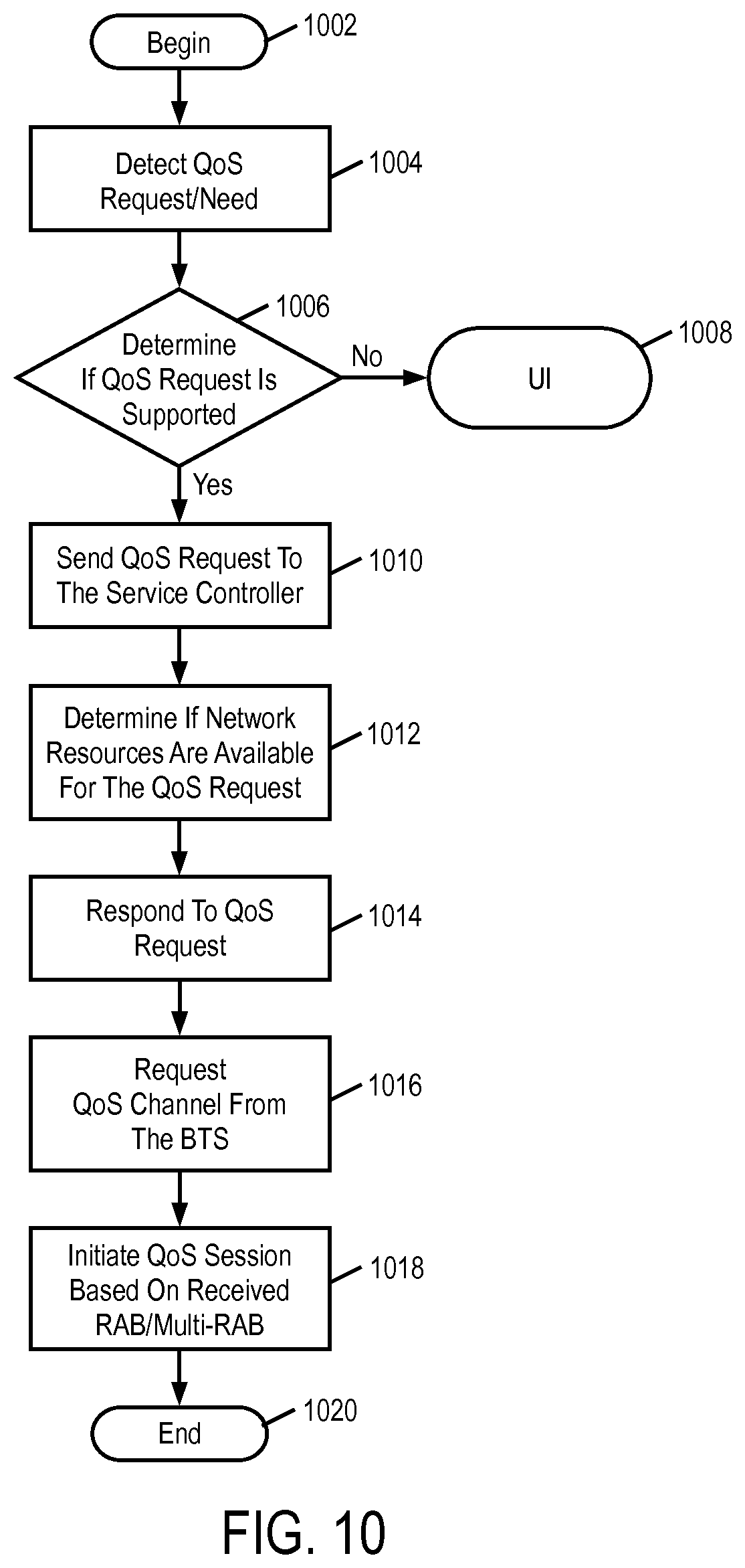
D00013
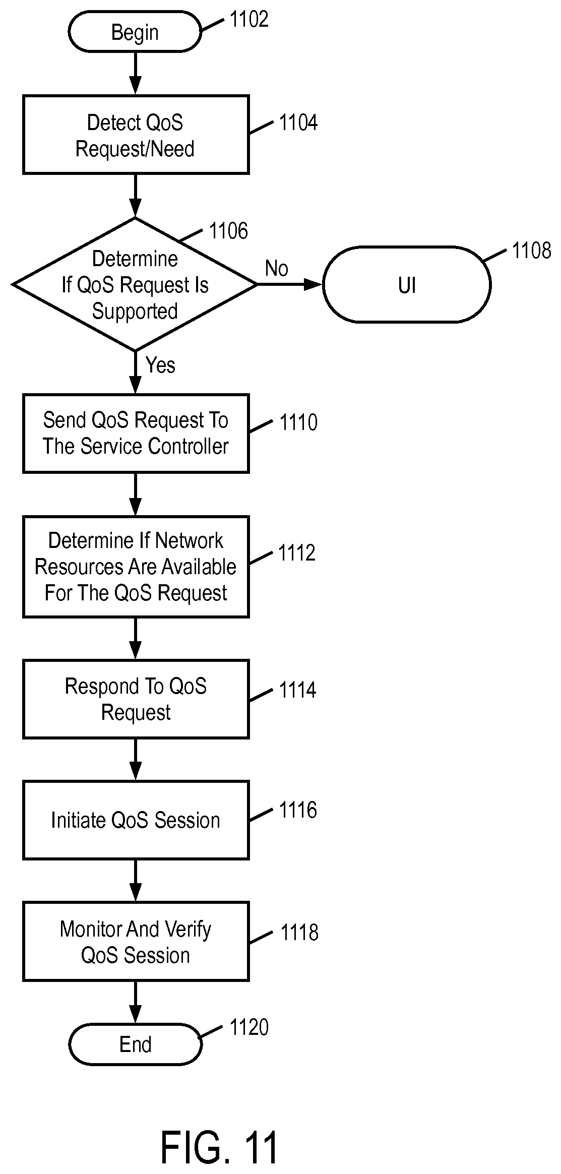
D00014

D00015
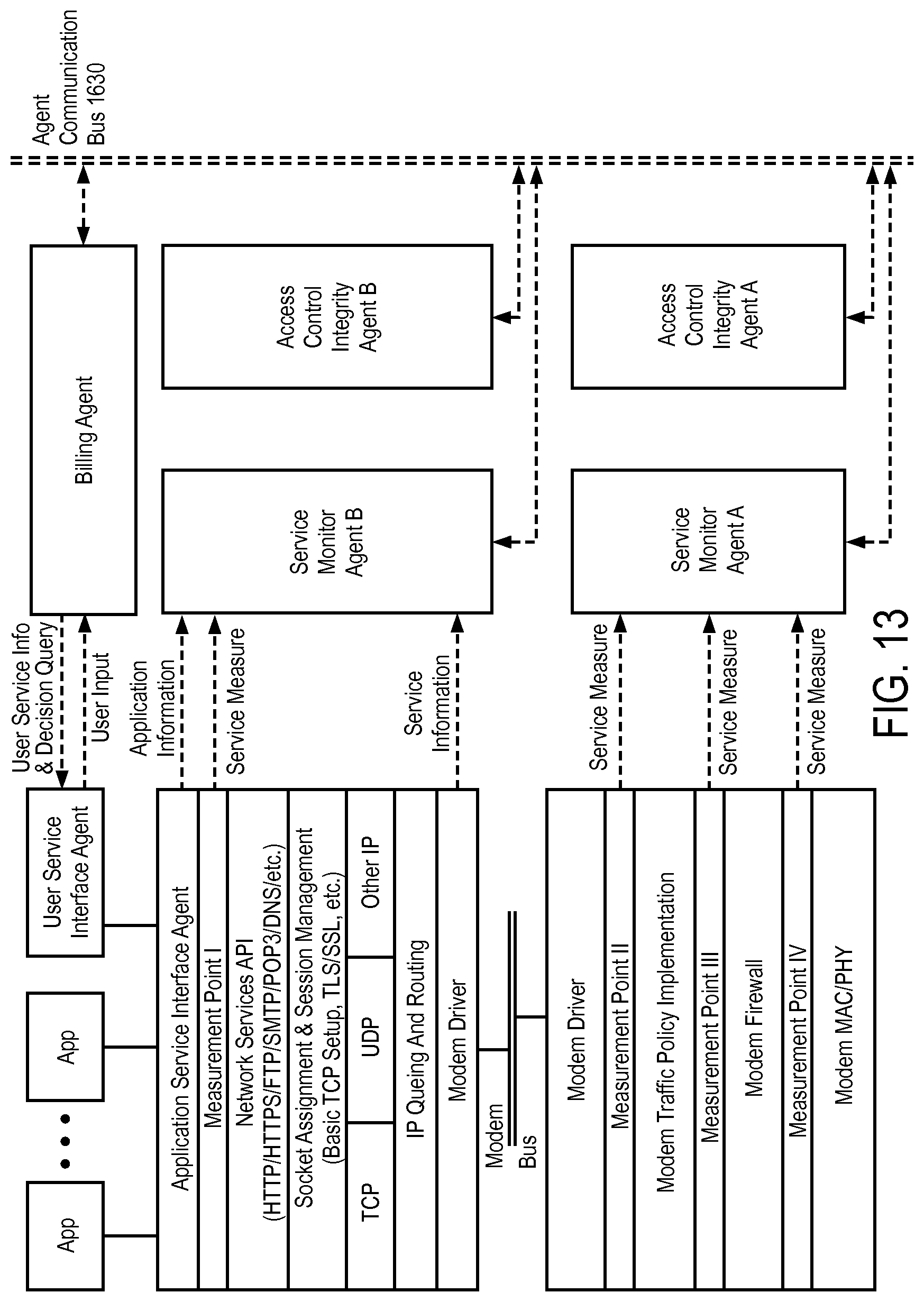
D00016
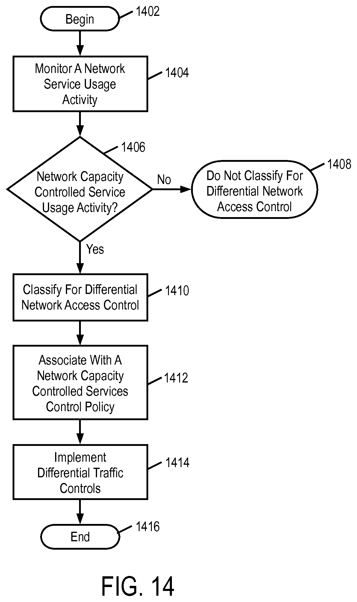
D00017
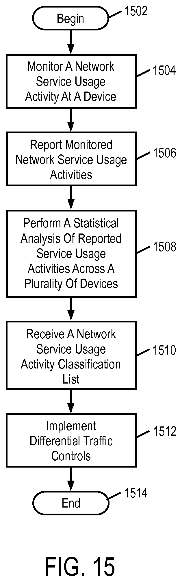
D00018
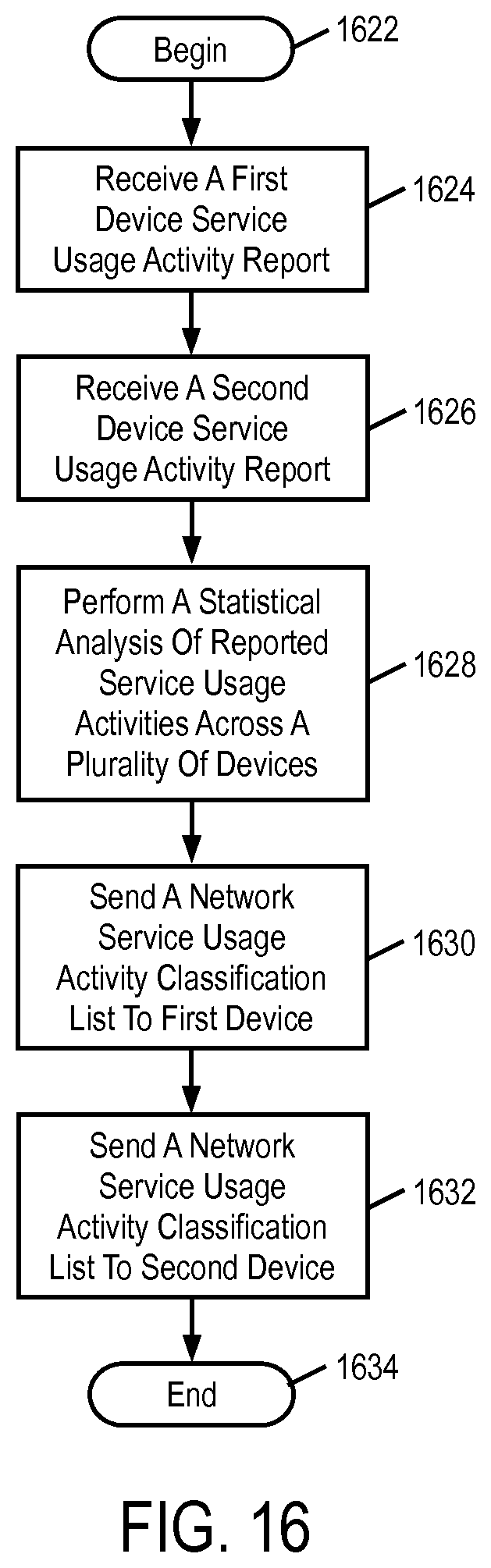
D00019

D00020
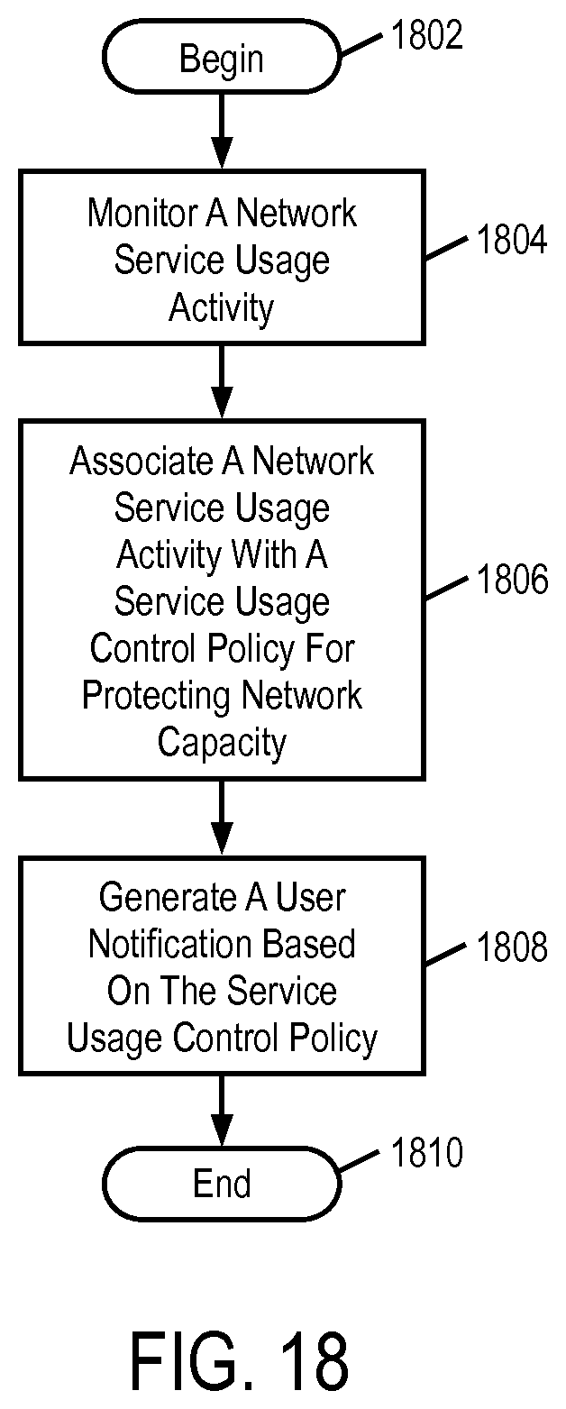
D00021
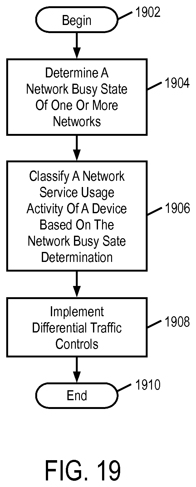
D00022

D00023

D00024
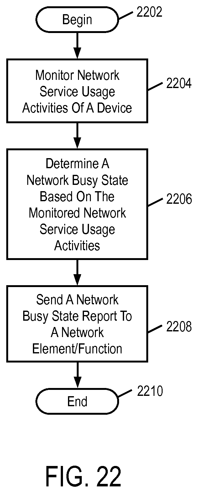
D00025
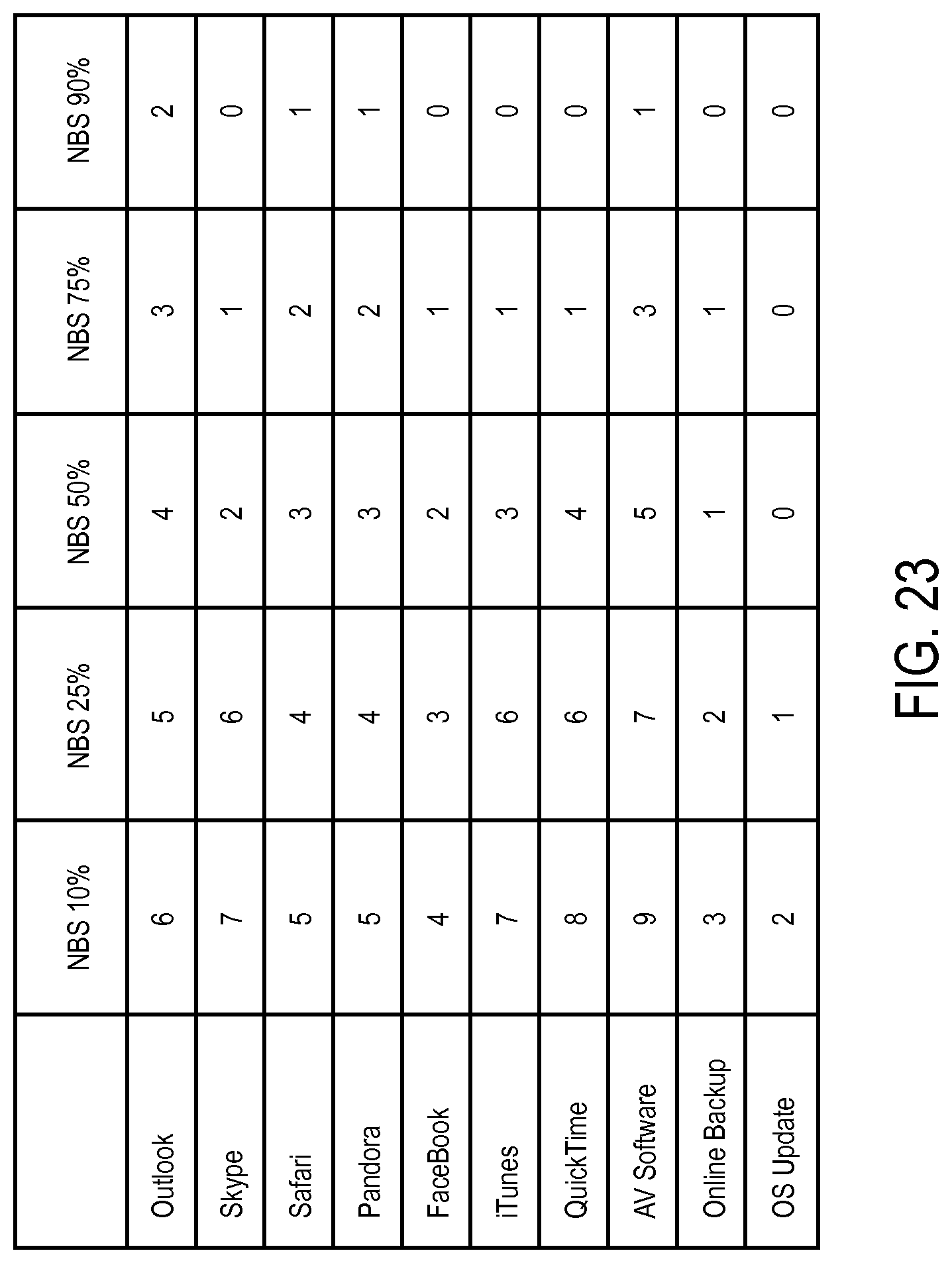
D00026
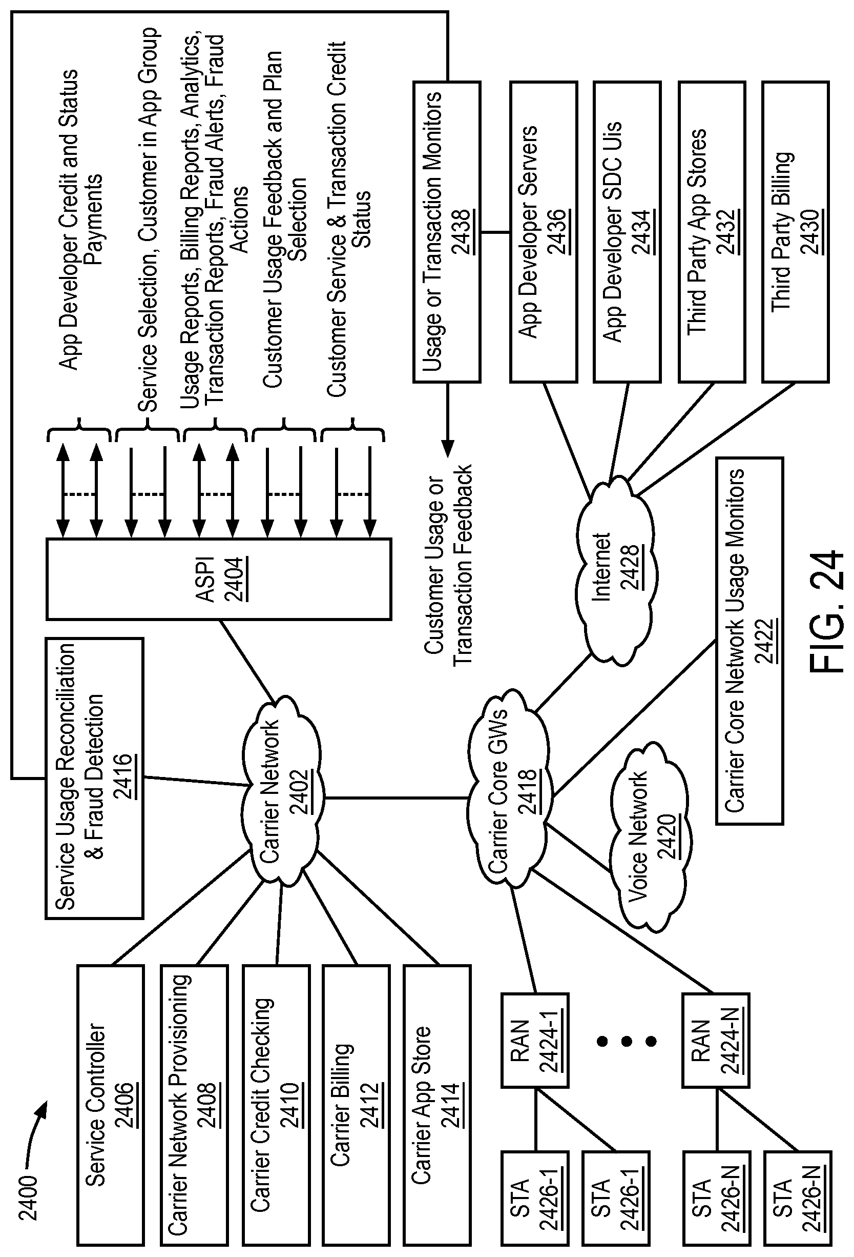
D00027

D00028
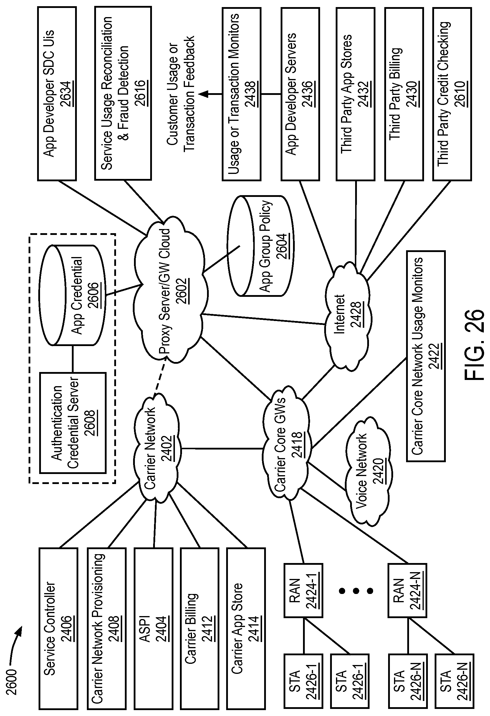
D00029

D00030

D00031
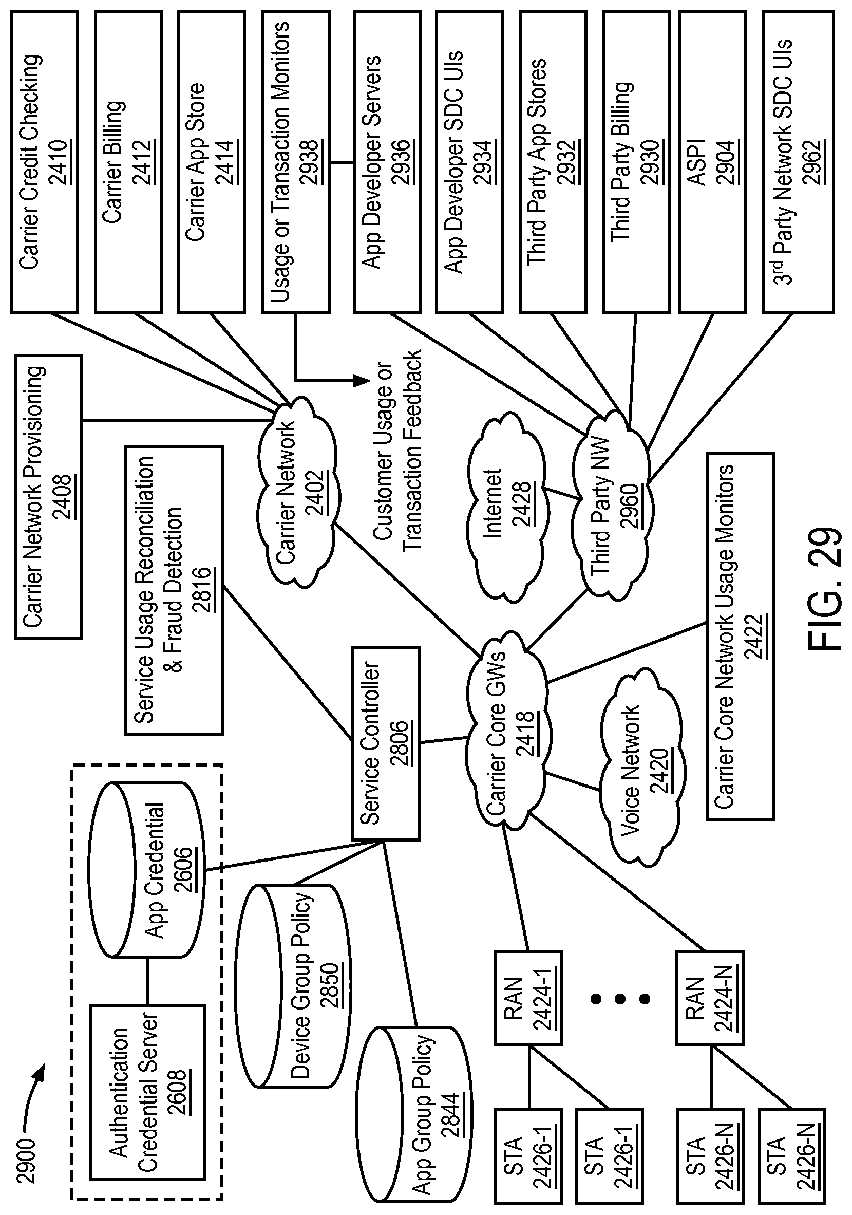
D00032
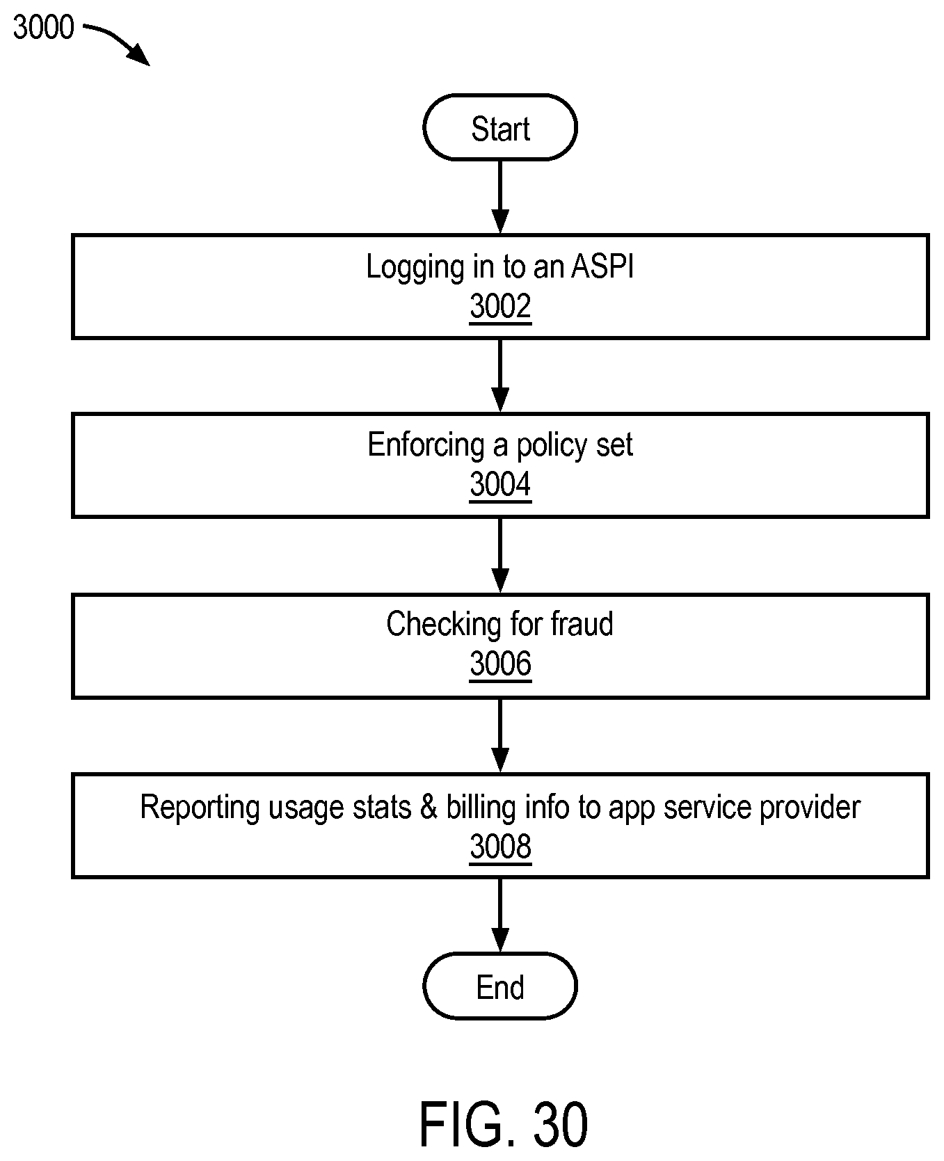
D00033
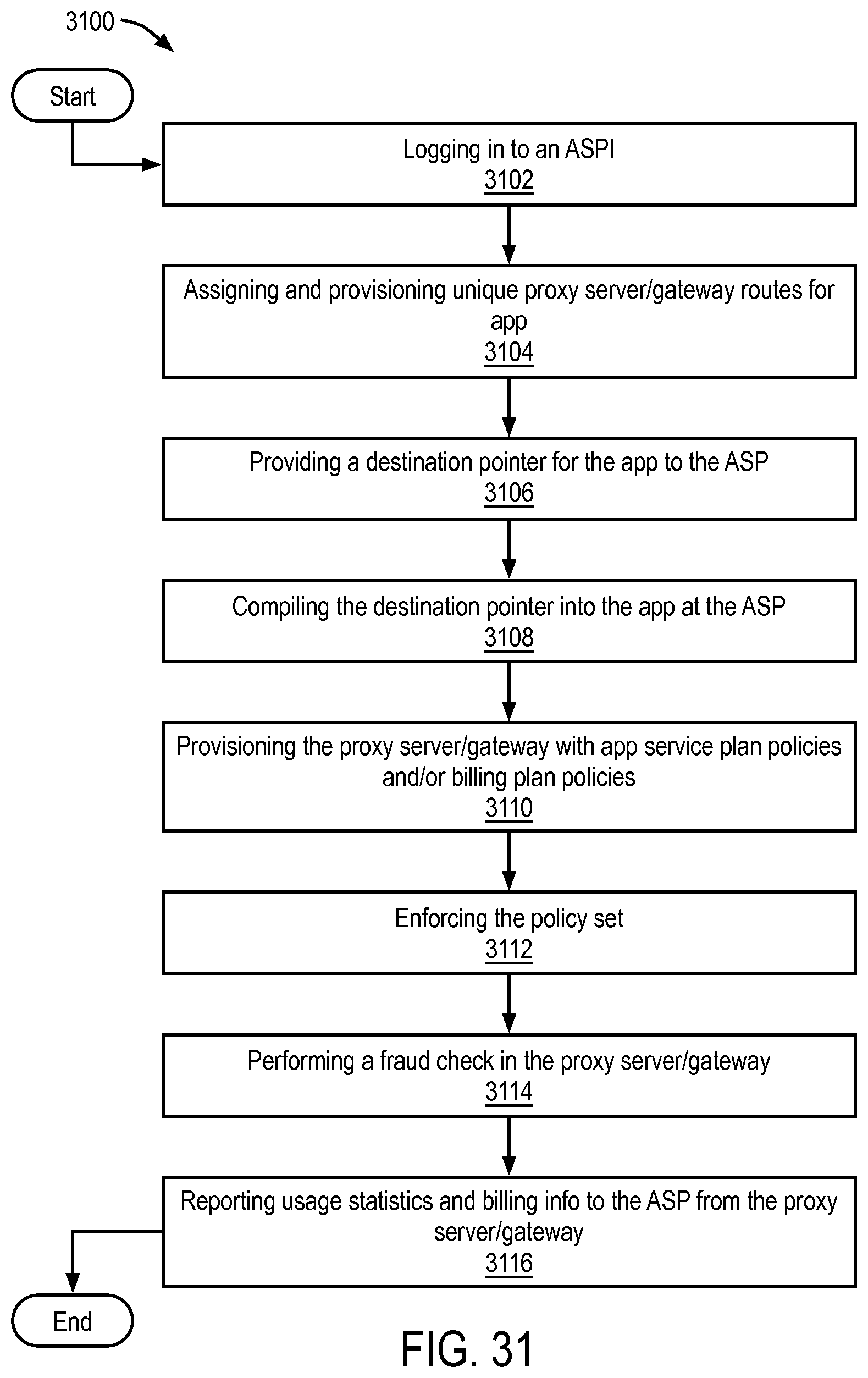
D00034
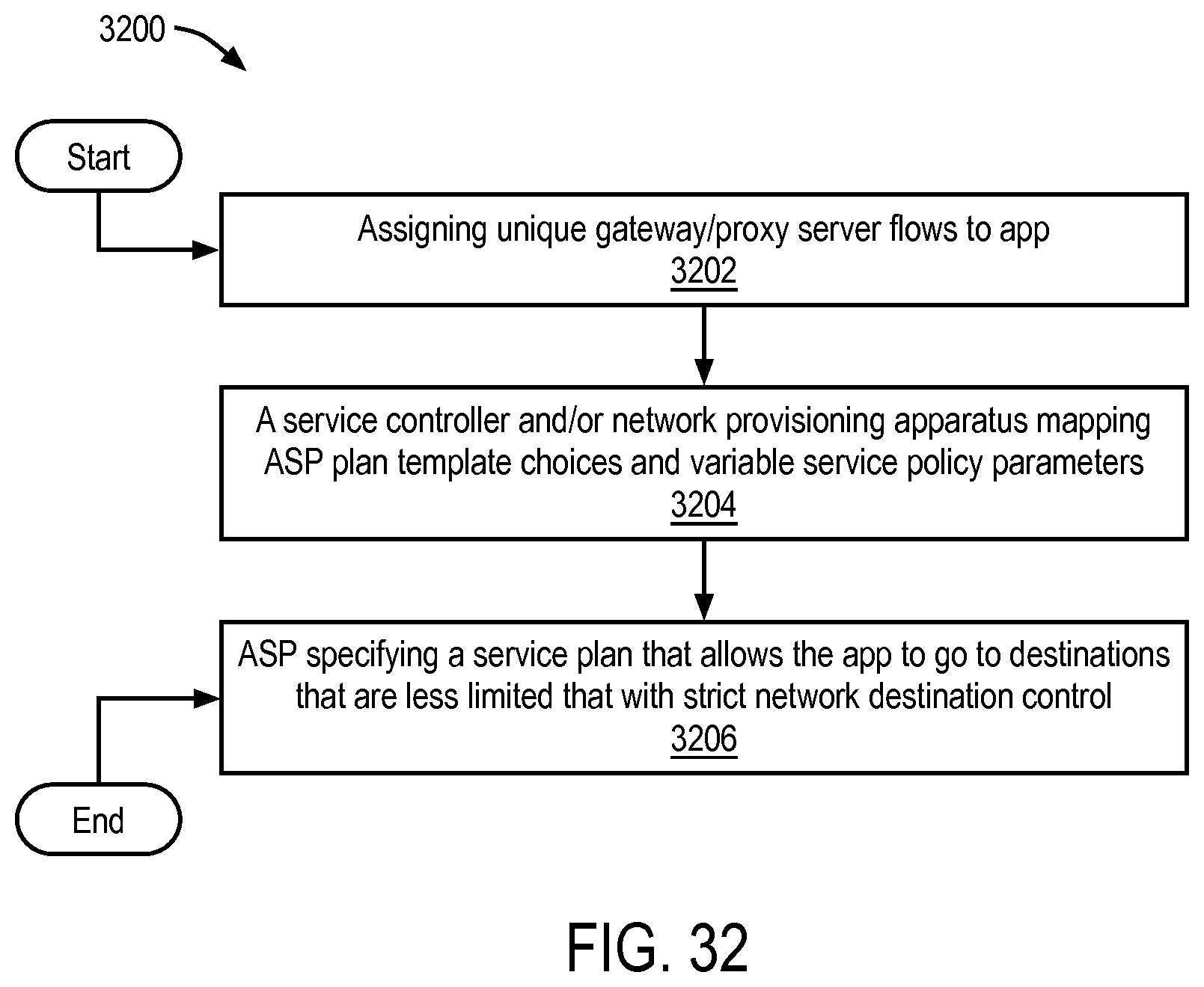
D00035
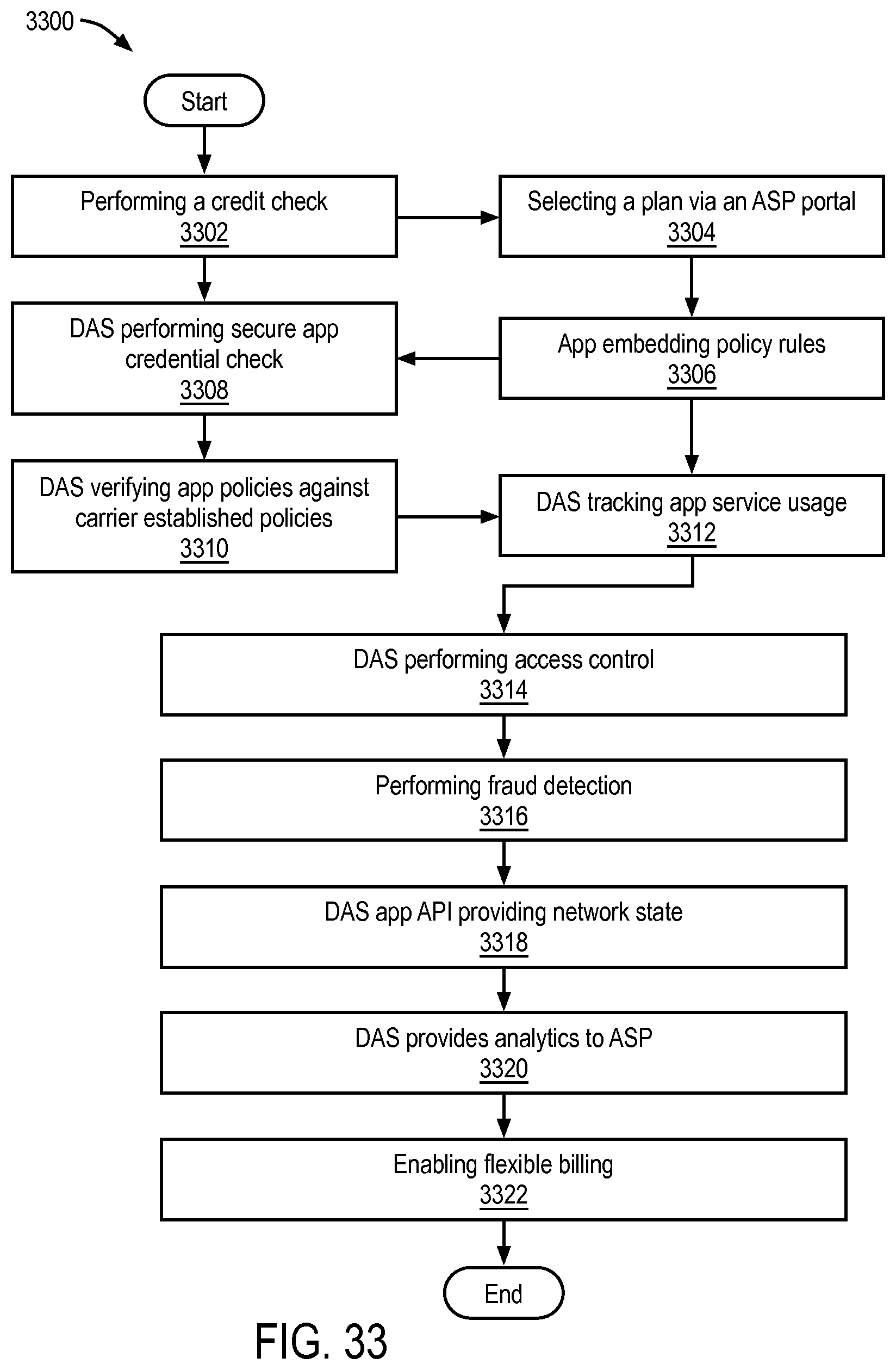
D00036
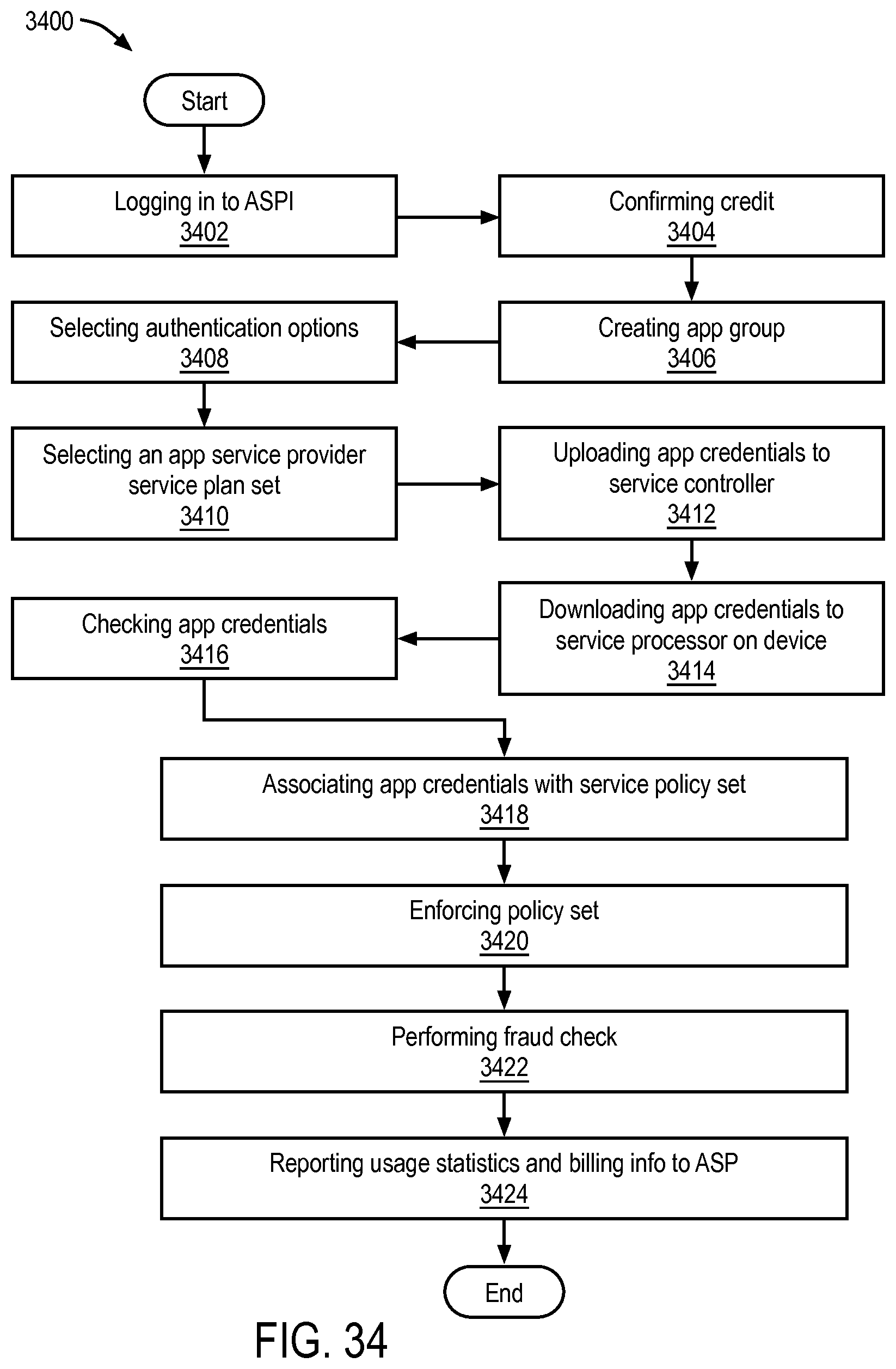
D00037
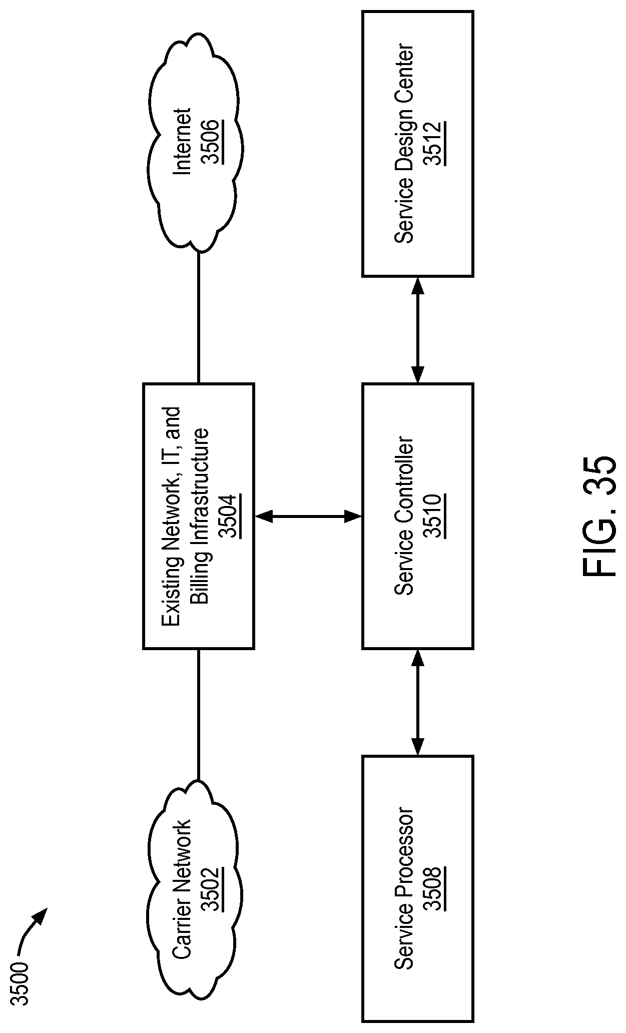
D00038
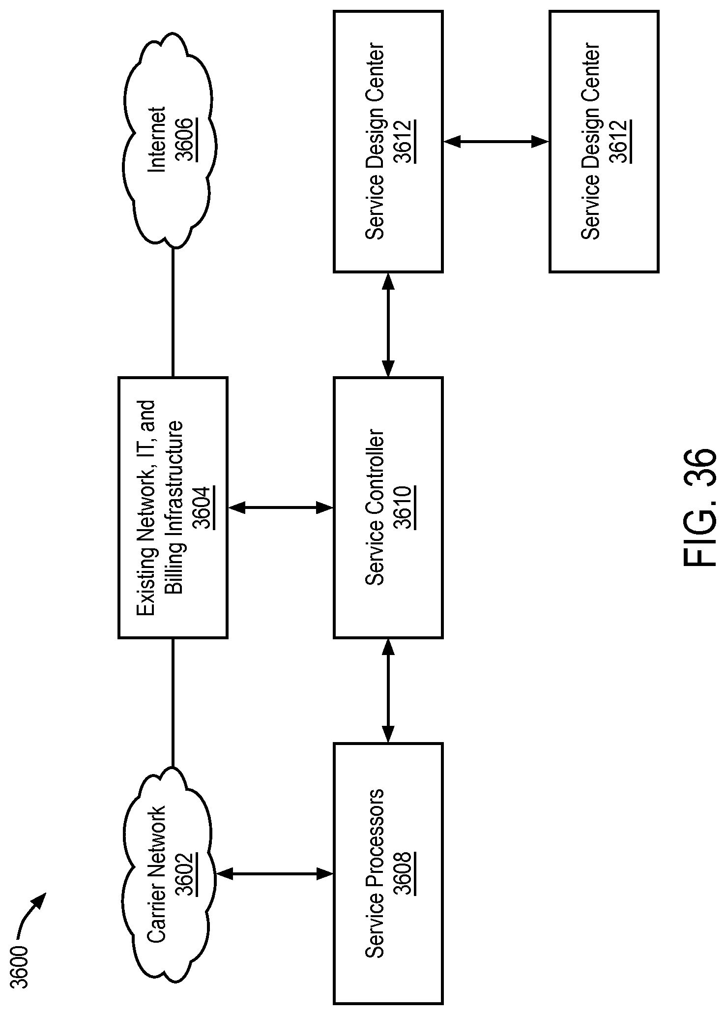
D00039
D00040
D00041

D00042
D00043
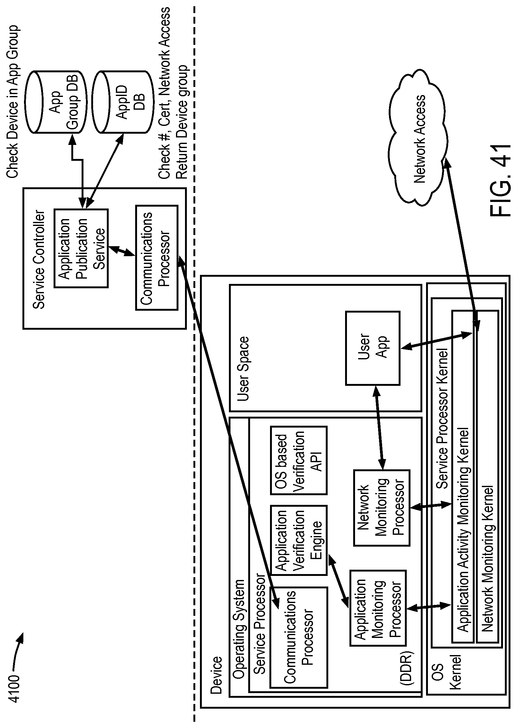
D00044

D00045
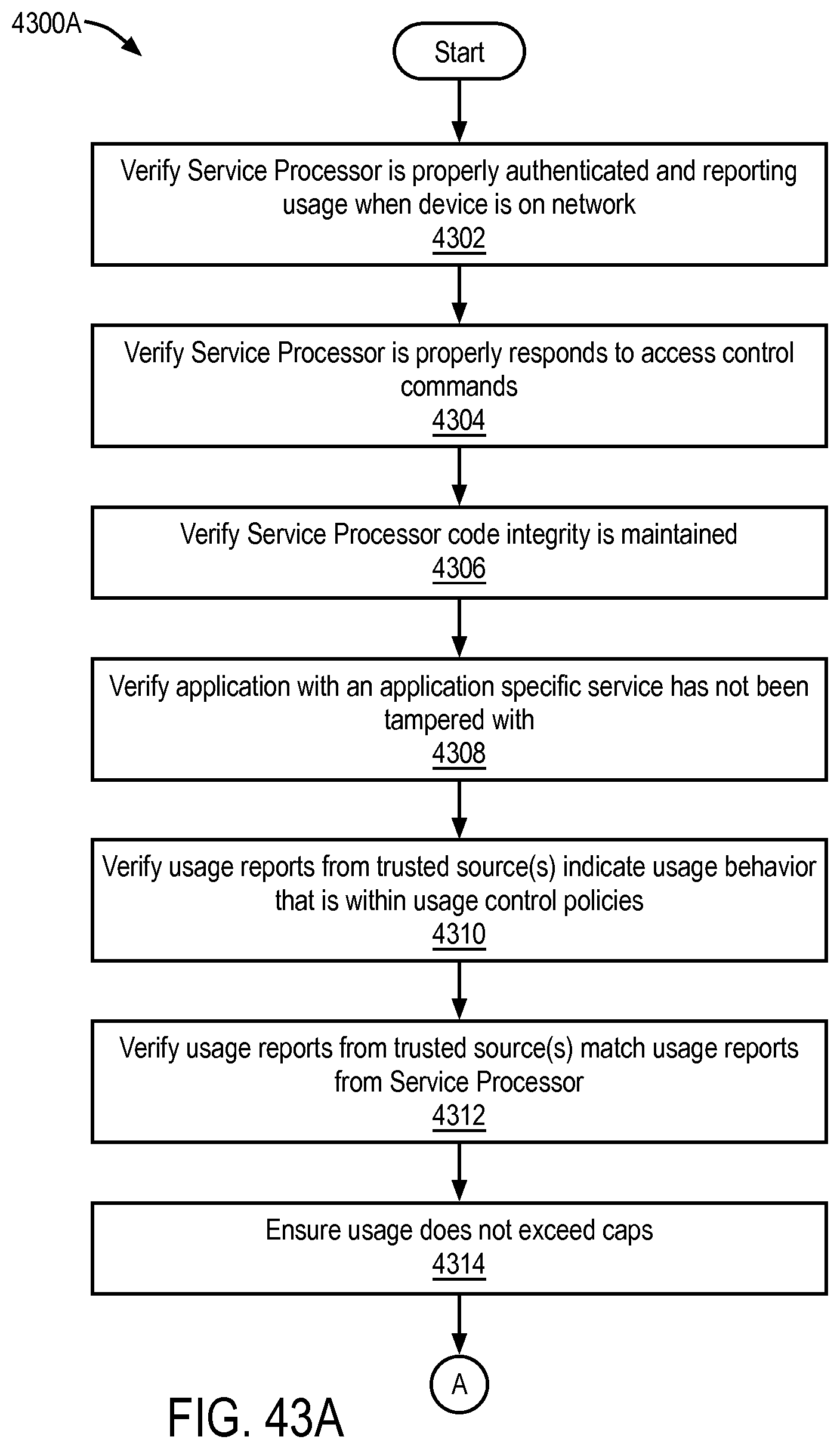
D00046

D00047
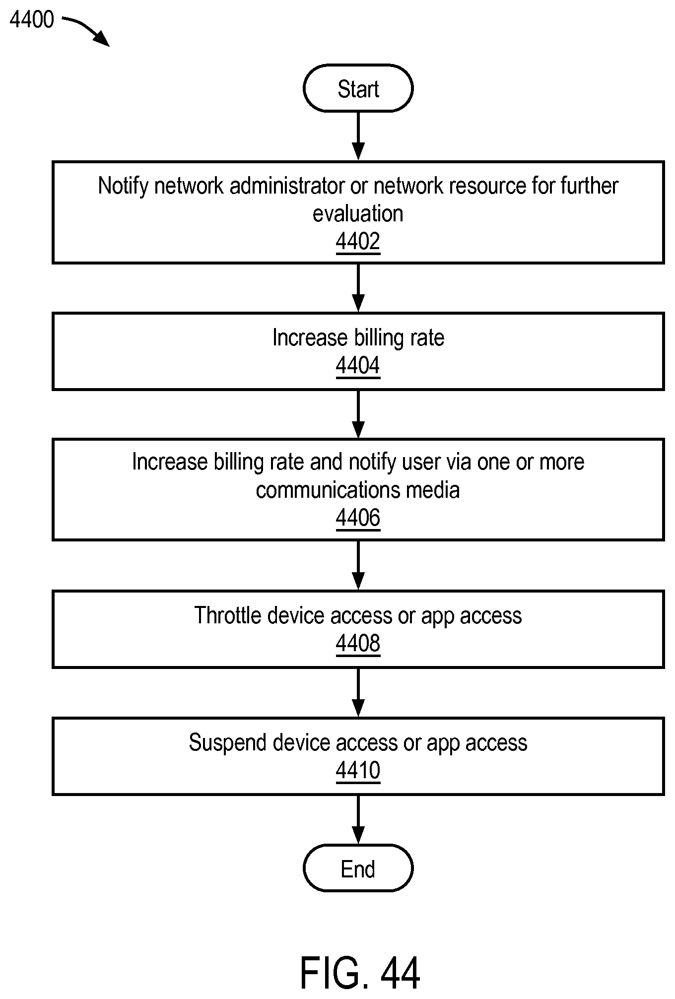
D00048

D00049
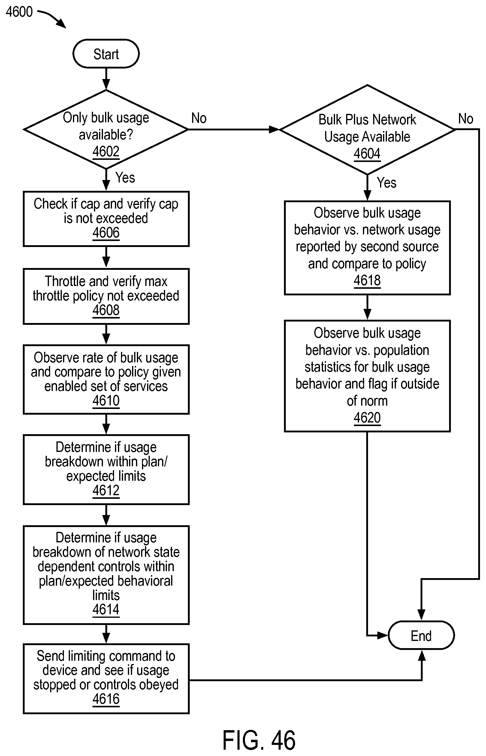
D00050
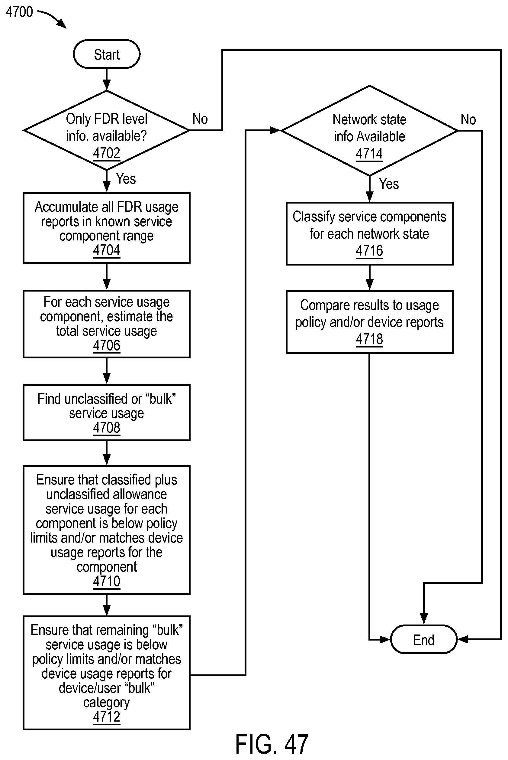
D00051

D00052
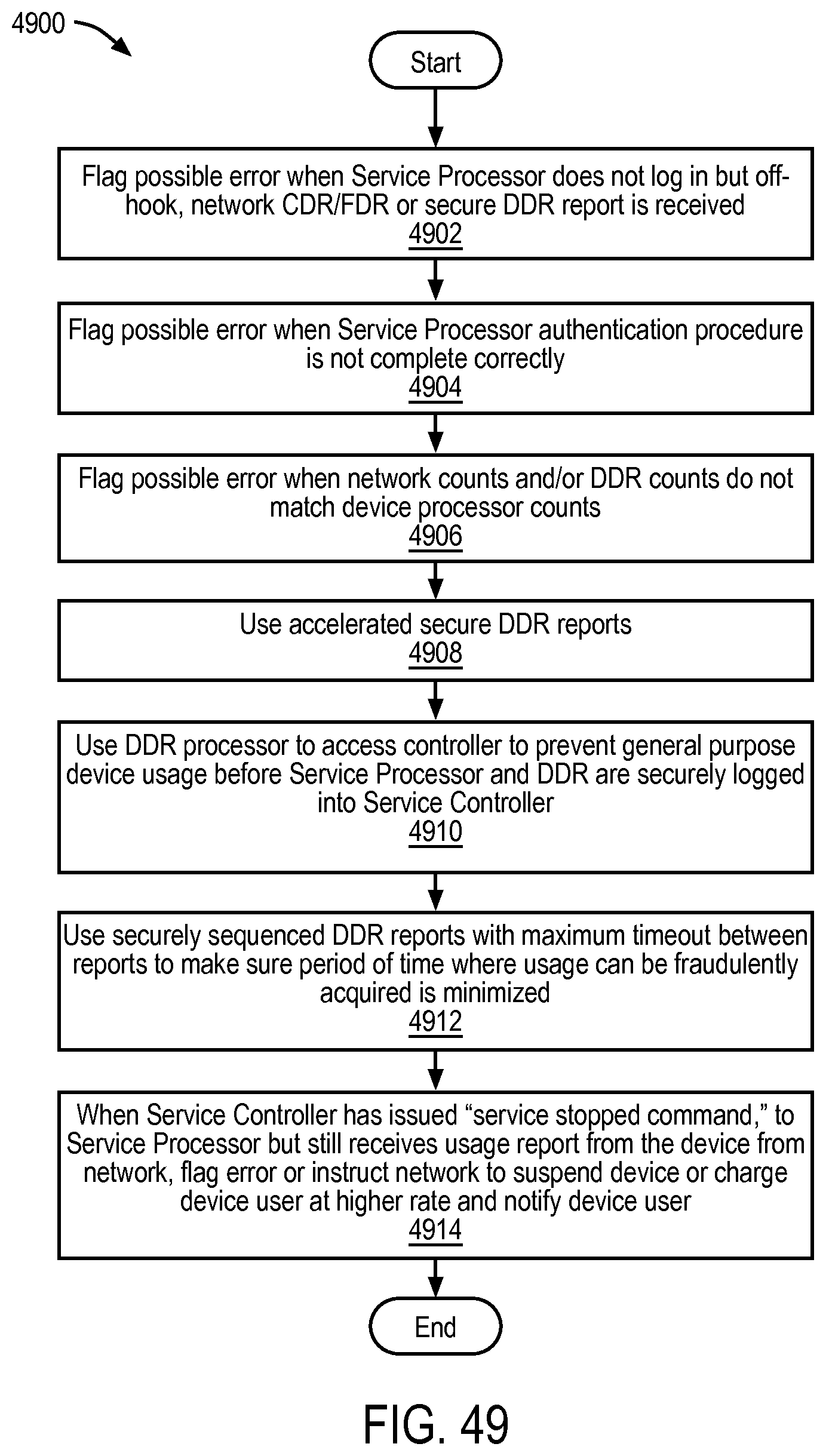
D00053
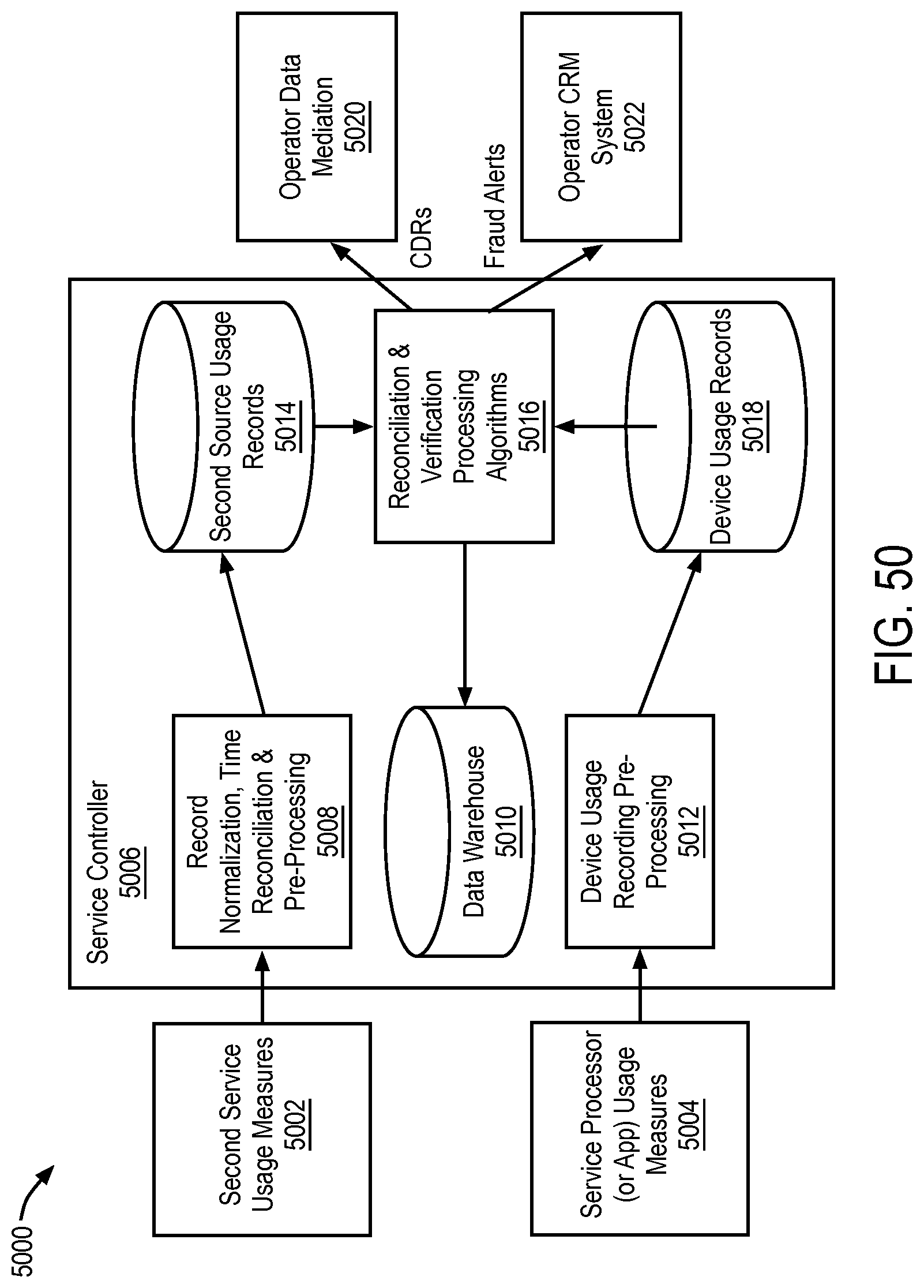
D00054
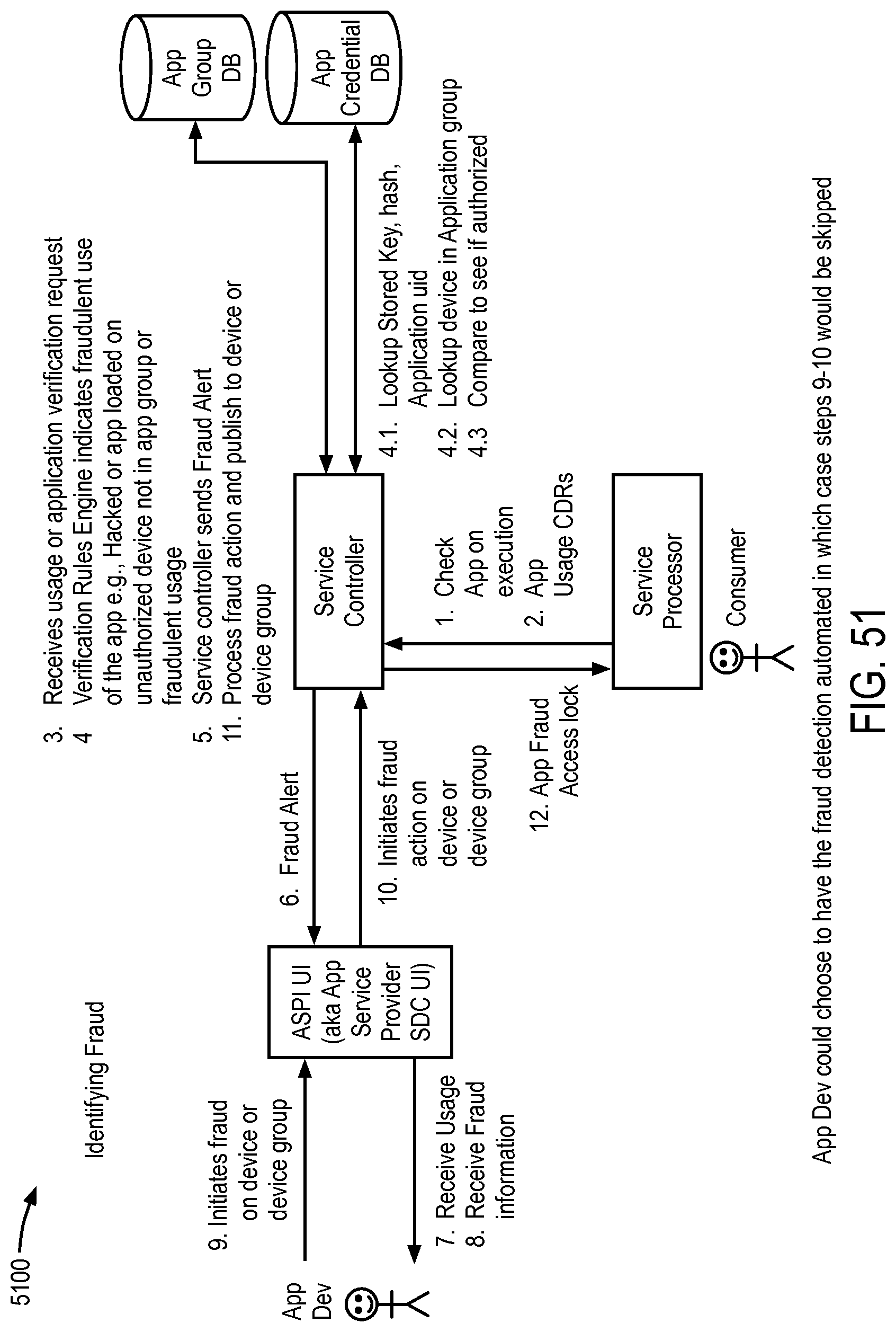
D00055
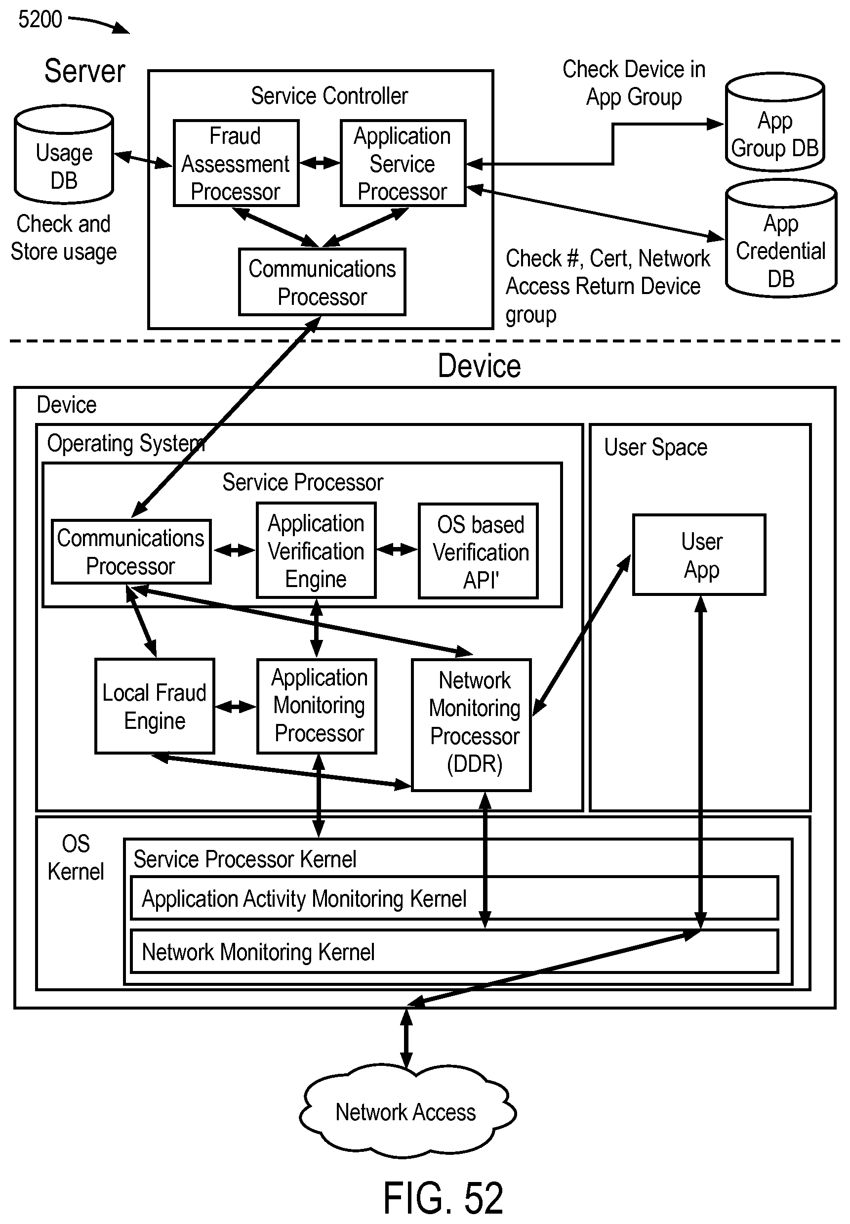
D00056
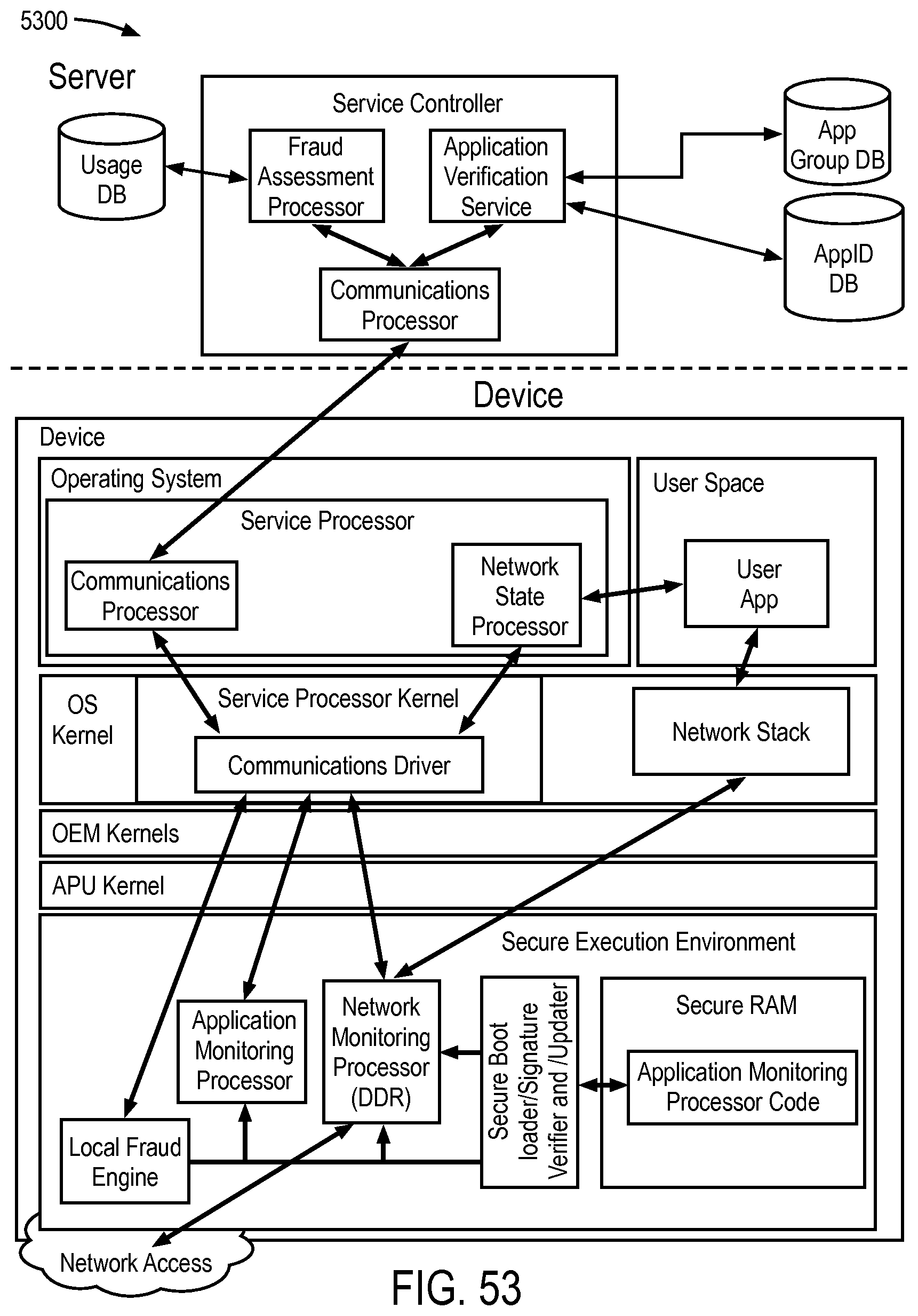
D00057
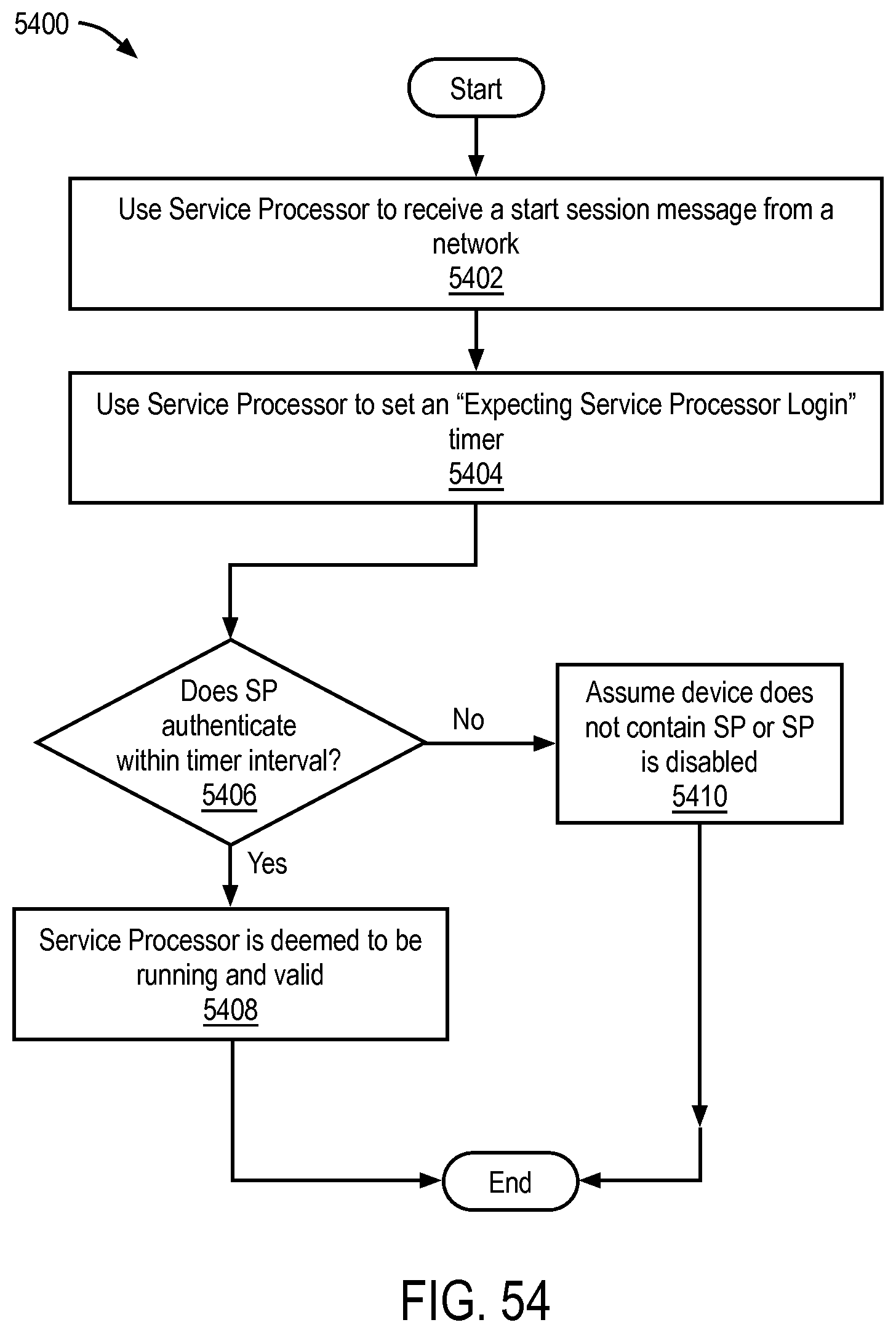
D00058
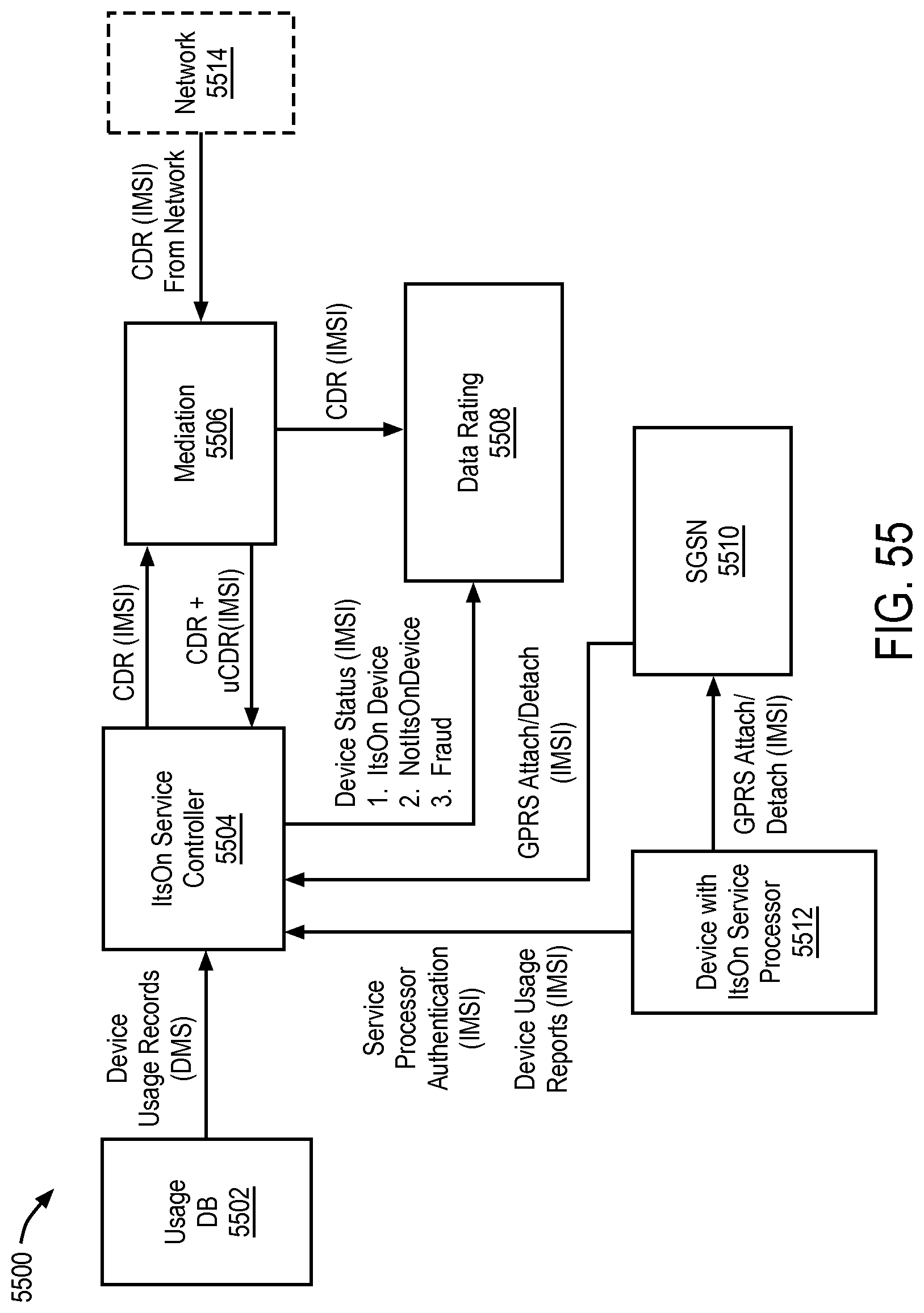
D00059
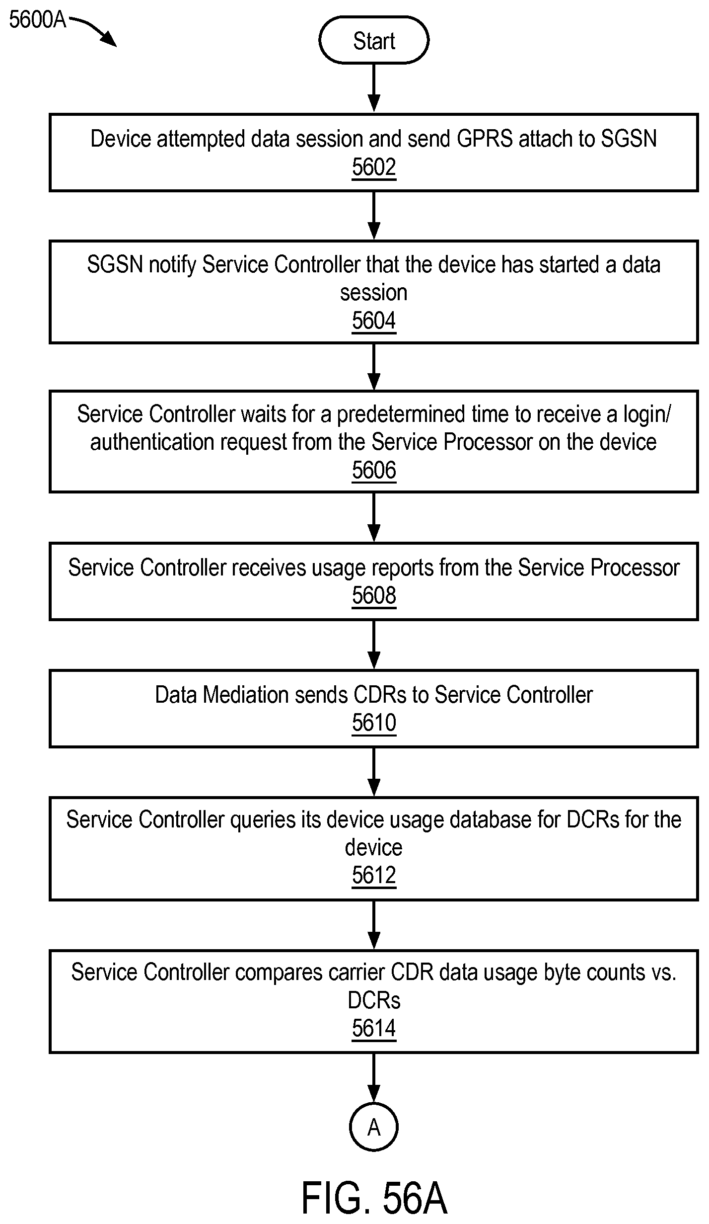
D00060
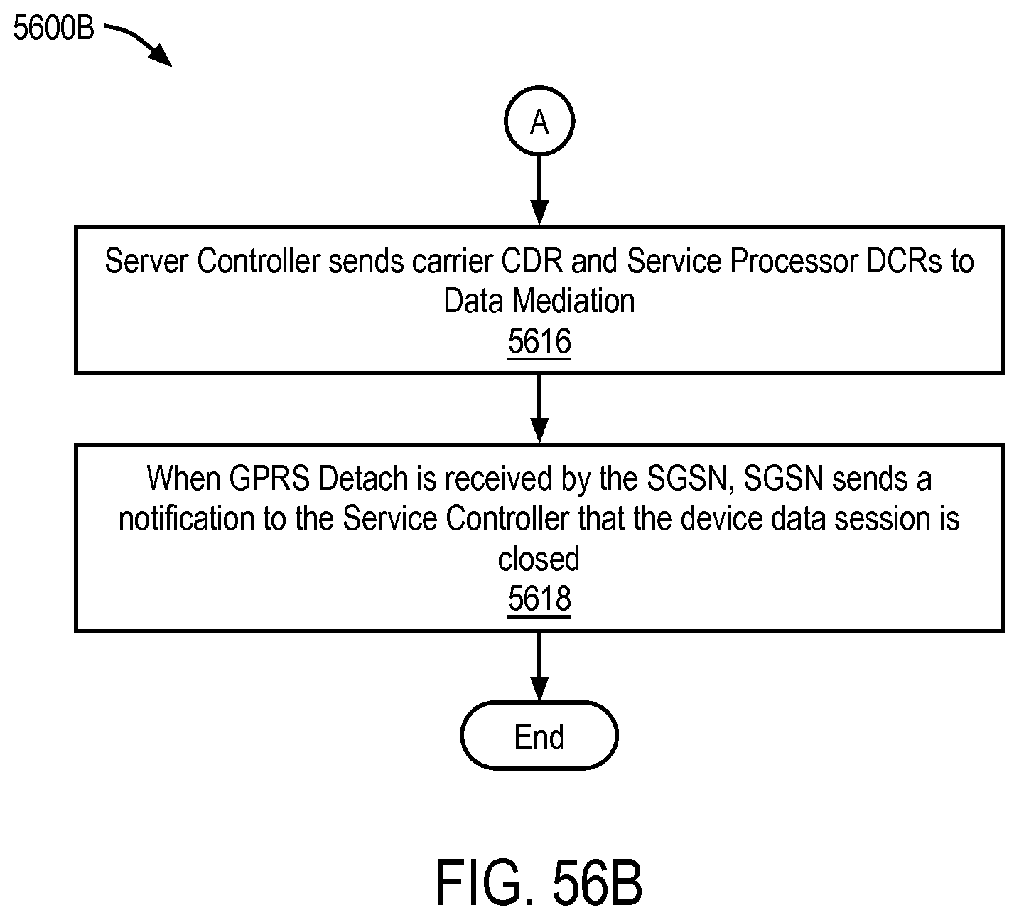
D00061
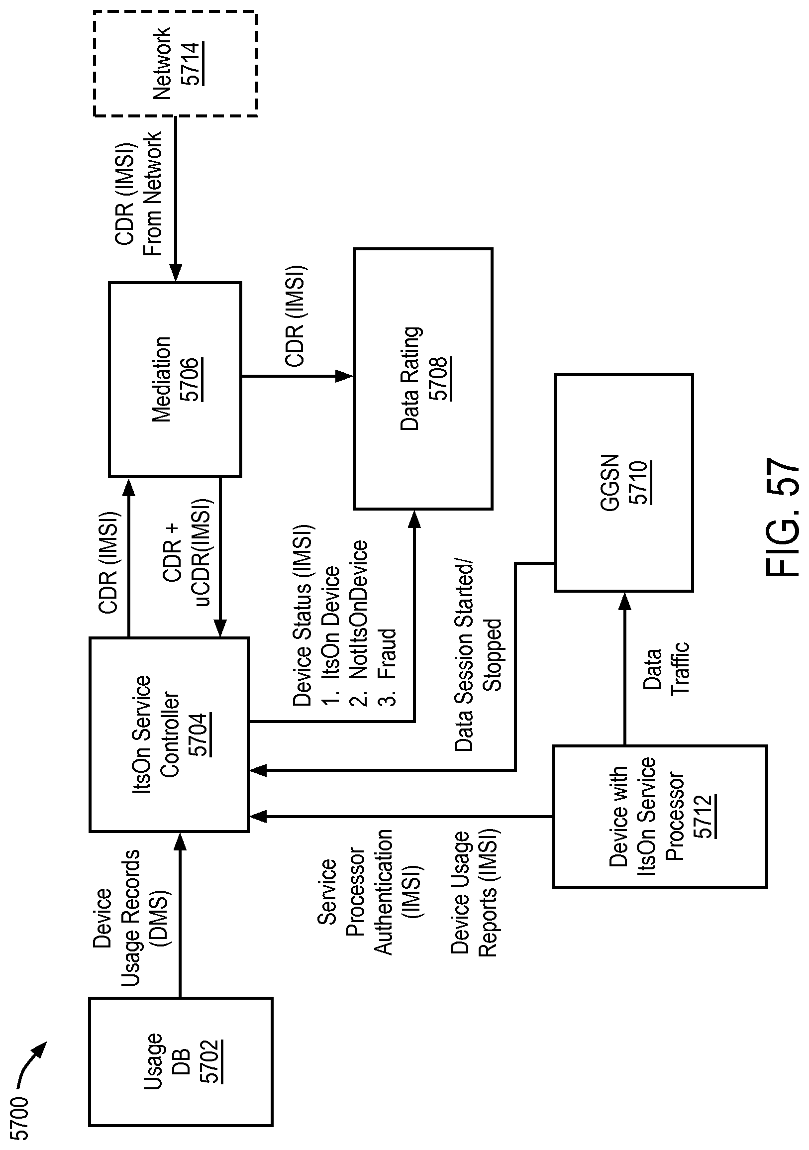
D00062
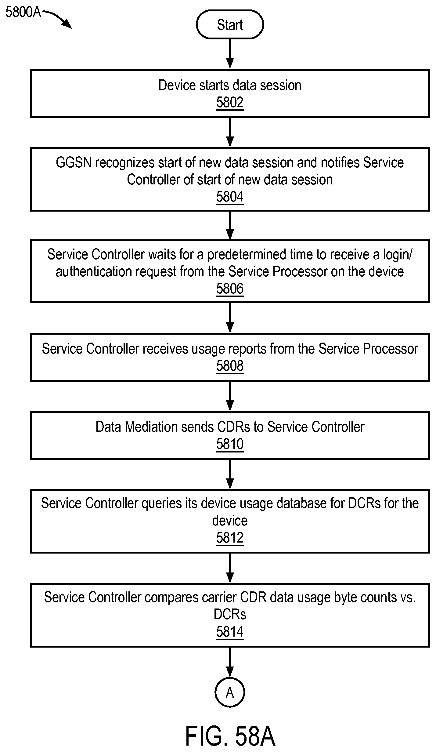
D00063
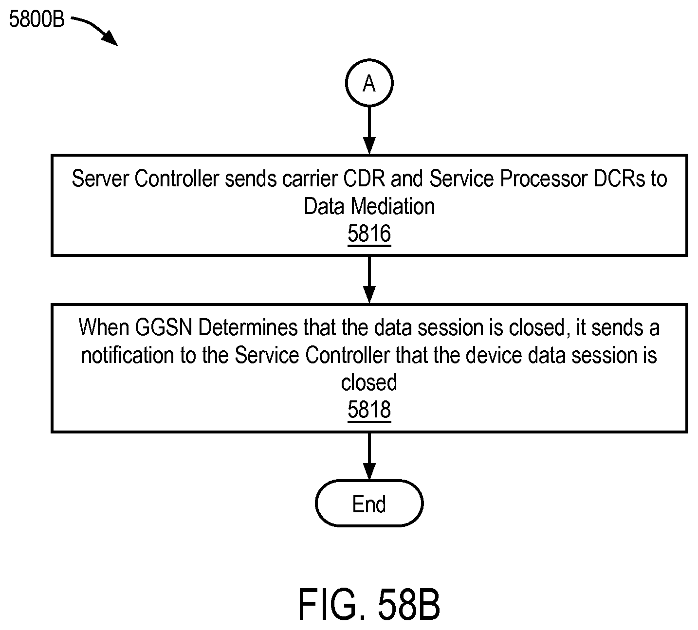
D00064
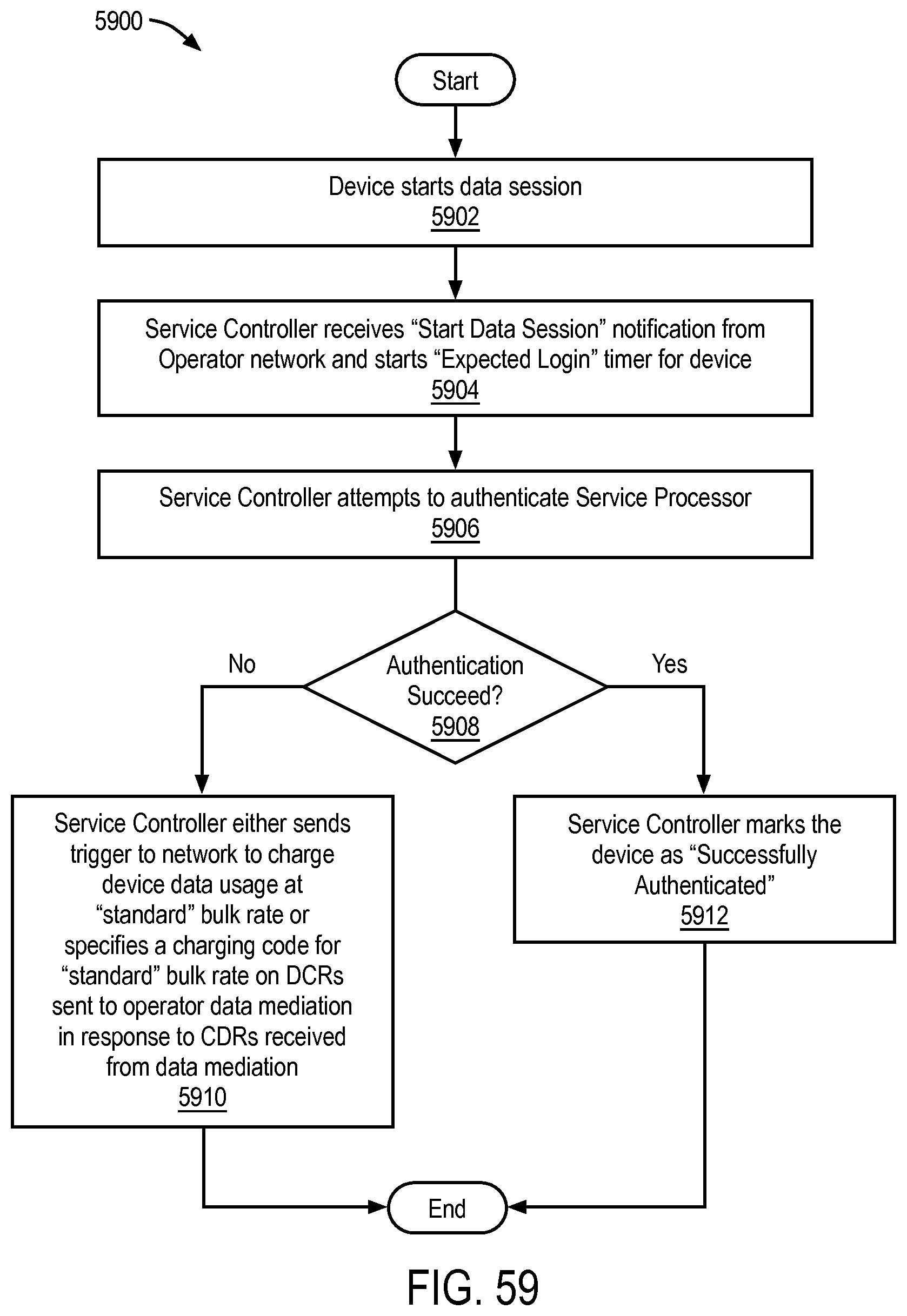
D00065
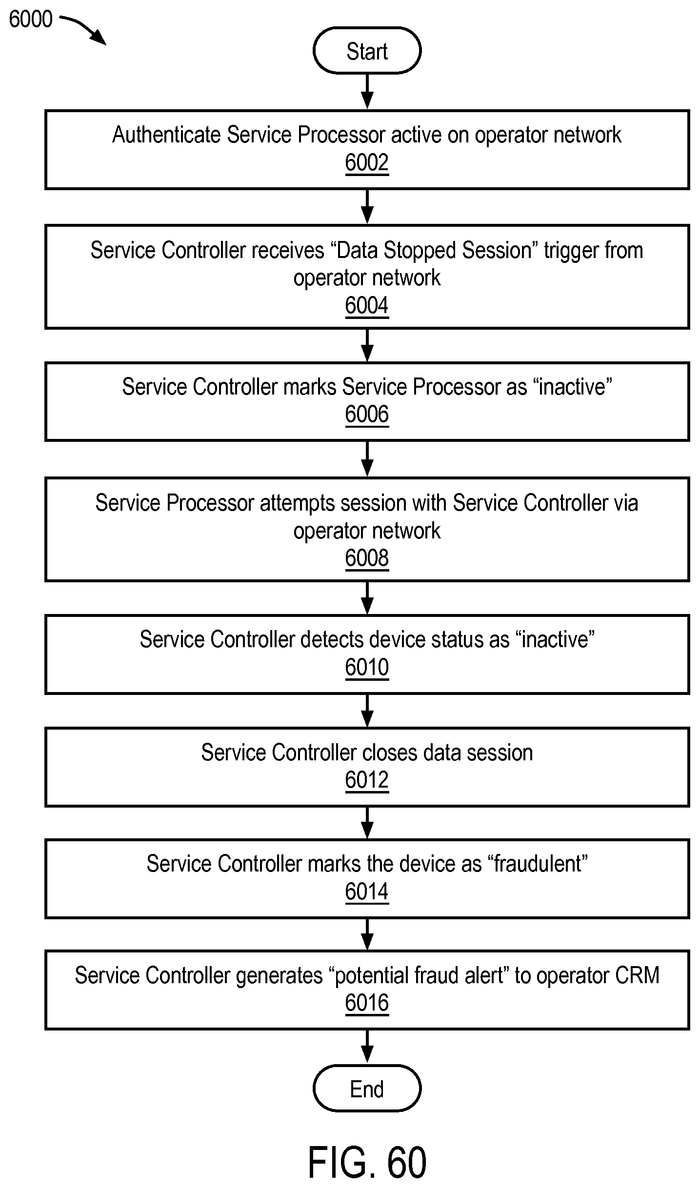
D00066
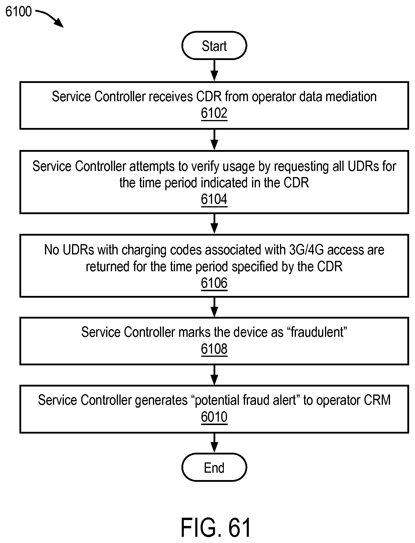
D00067
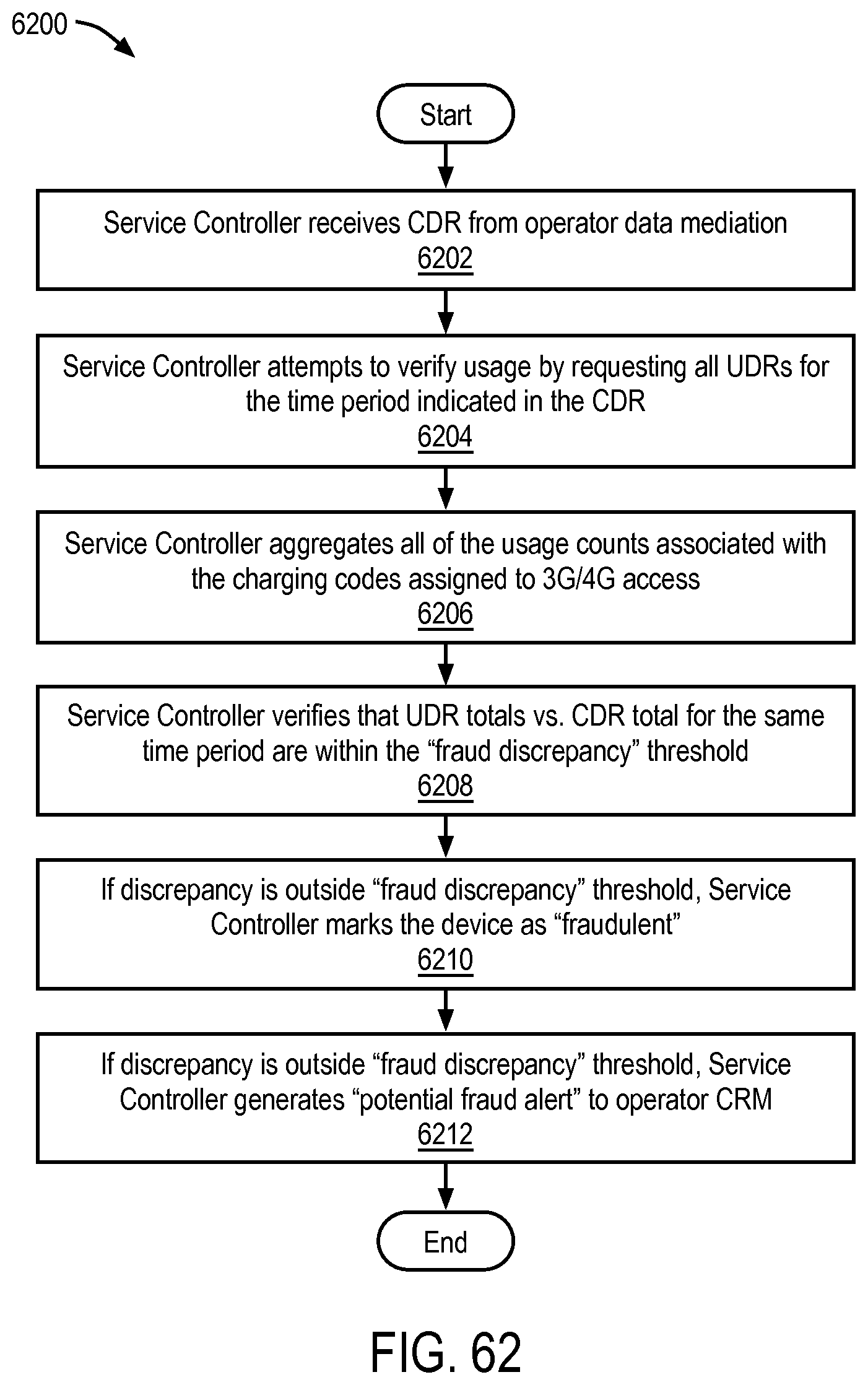
D00068
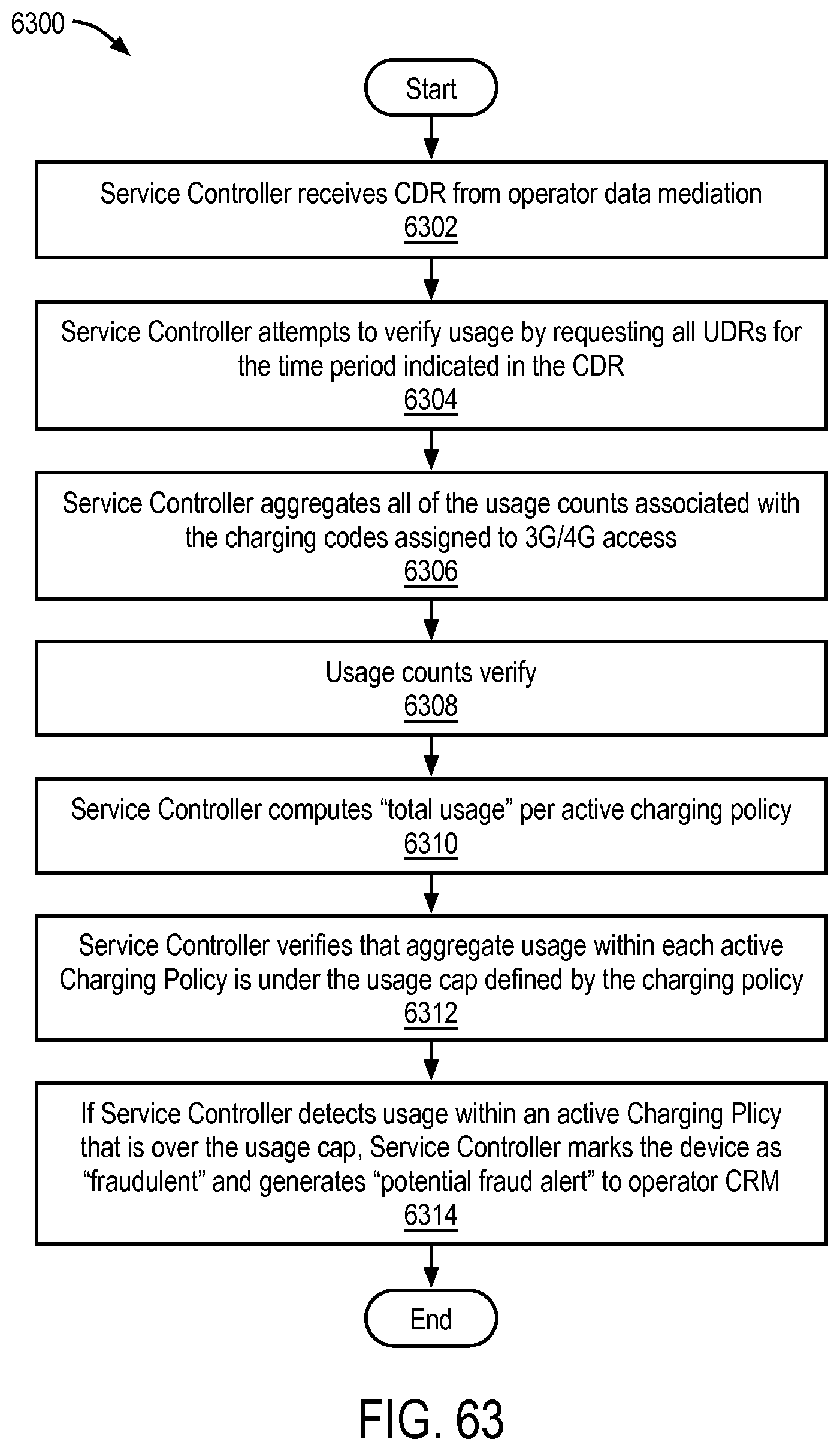
D00069
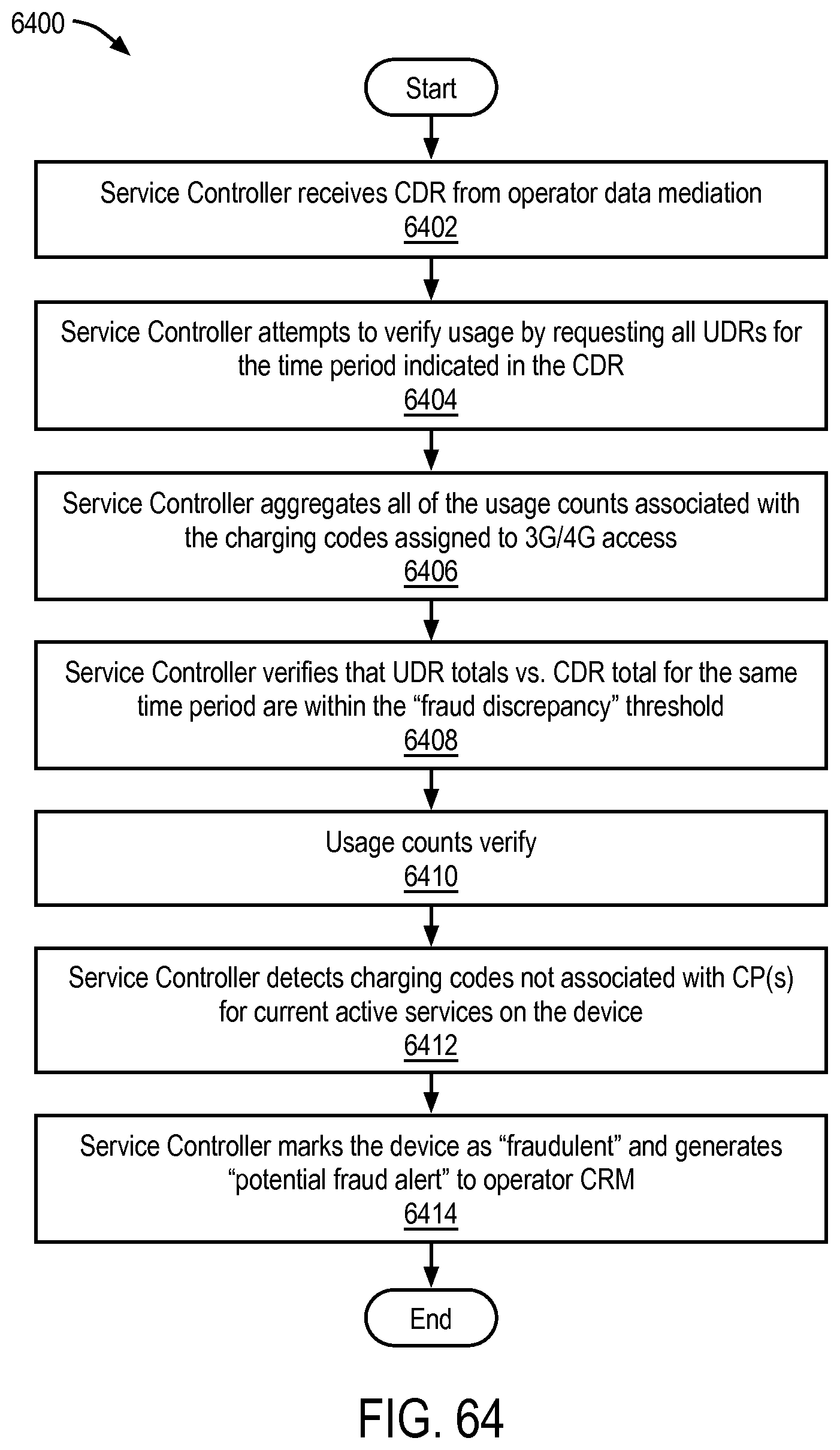
D00070
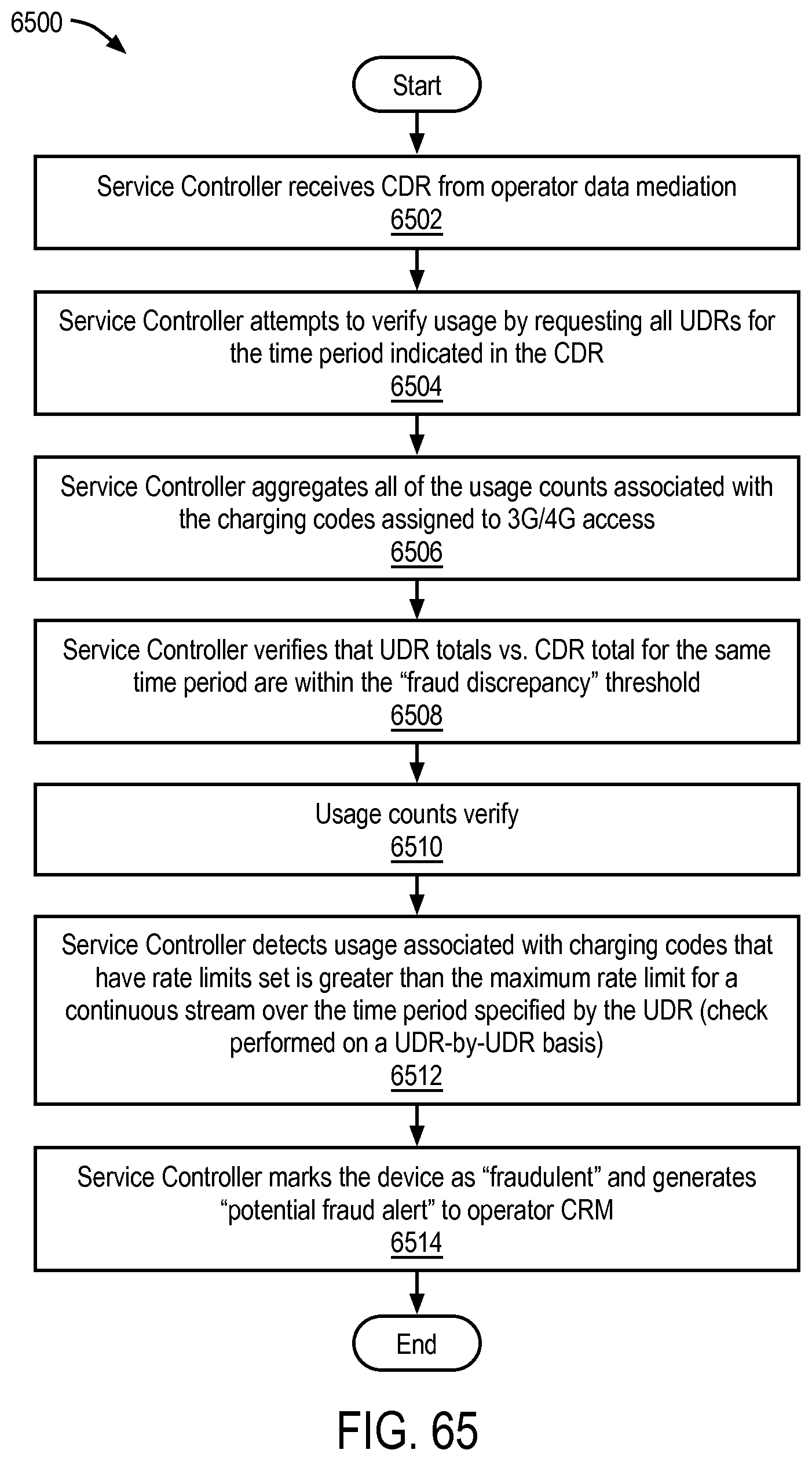
D00071
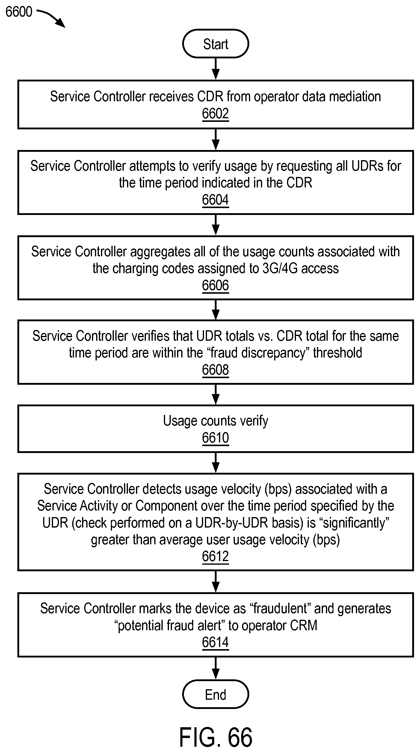
D00072
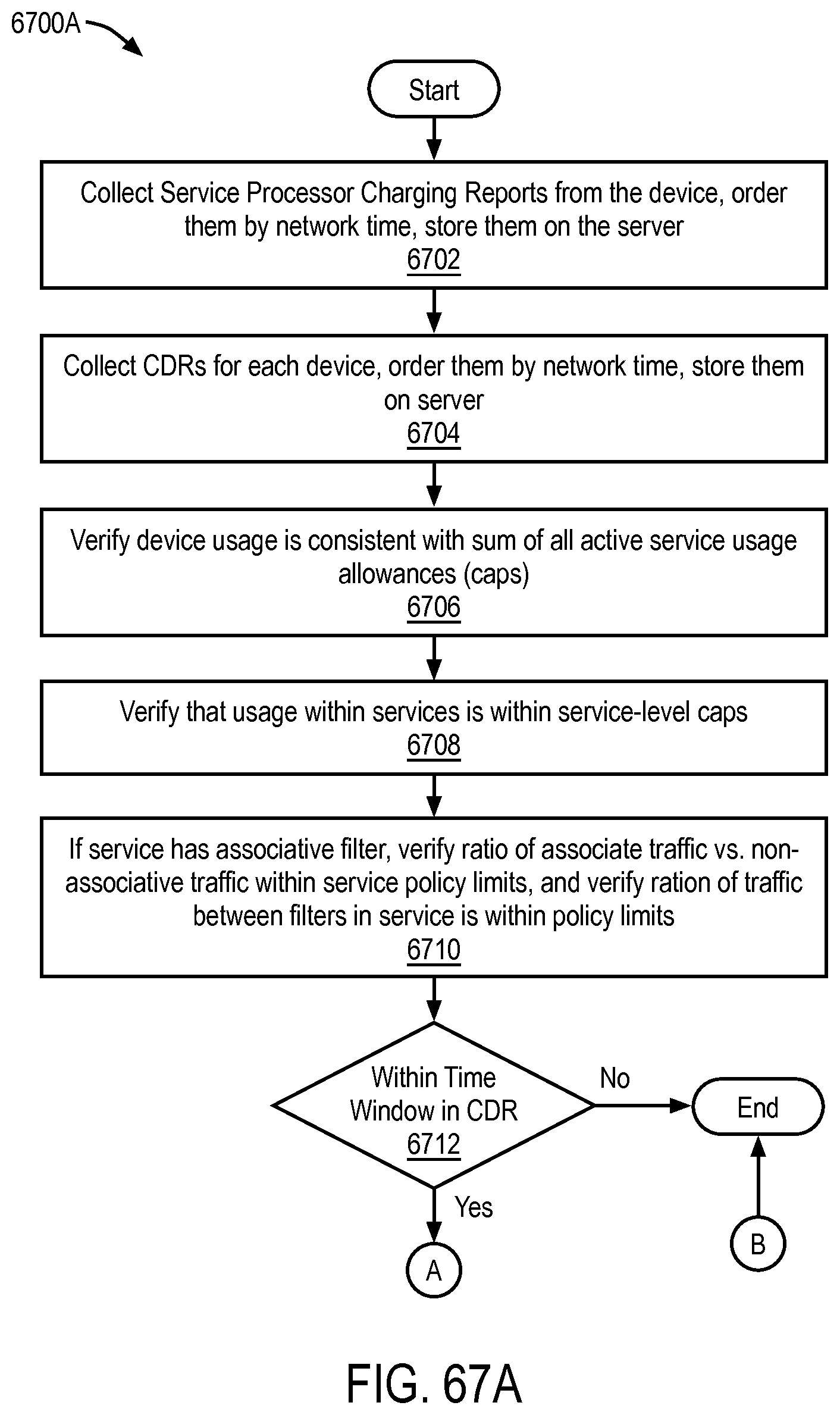
D00073
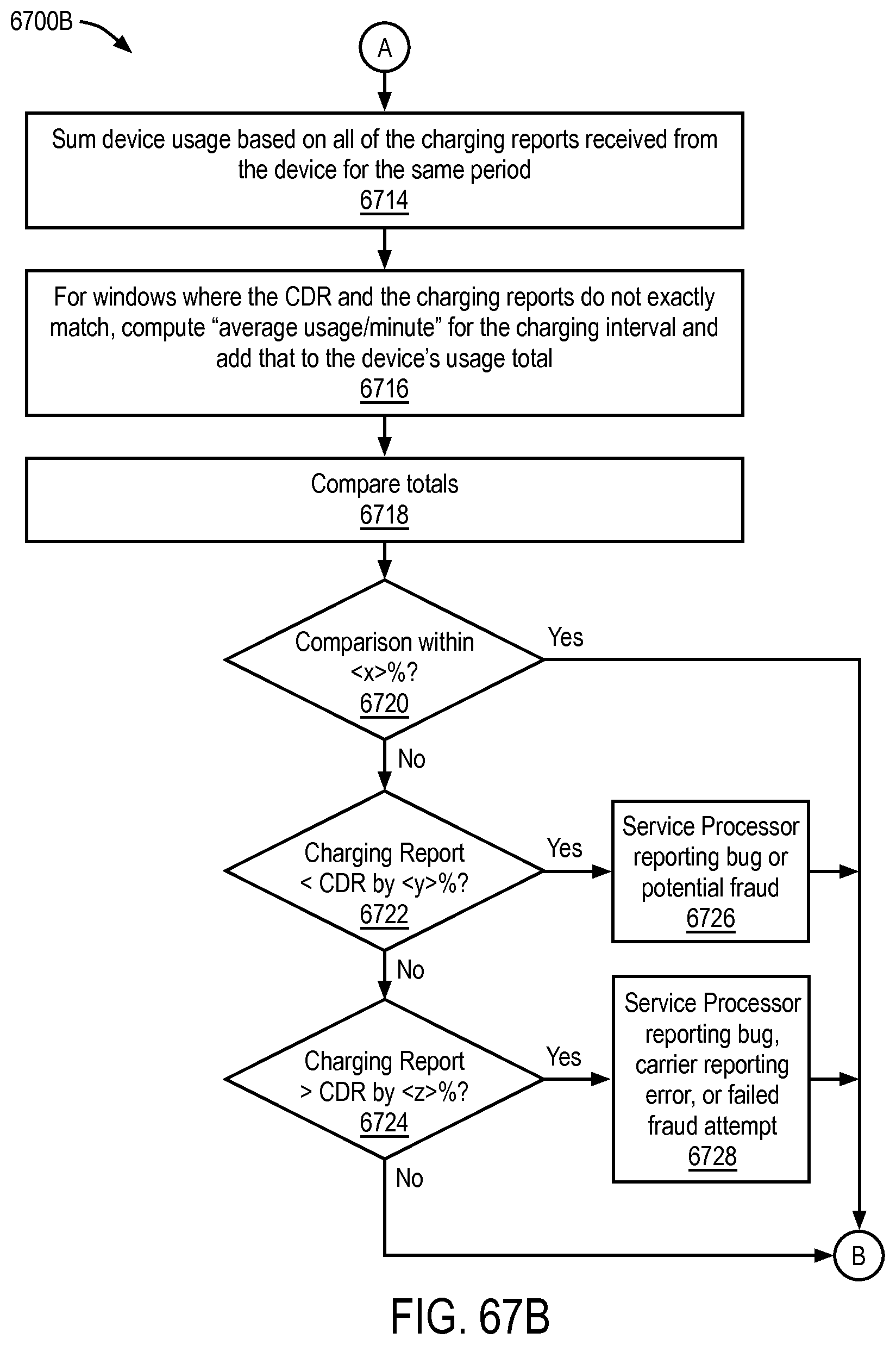
D00074
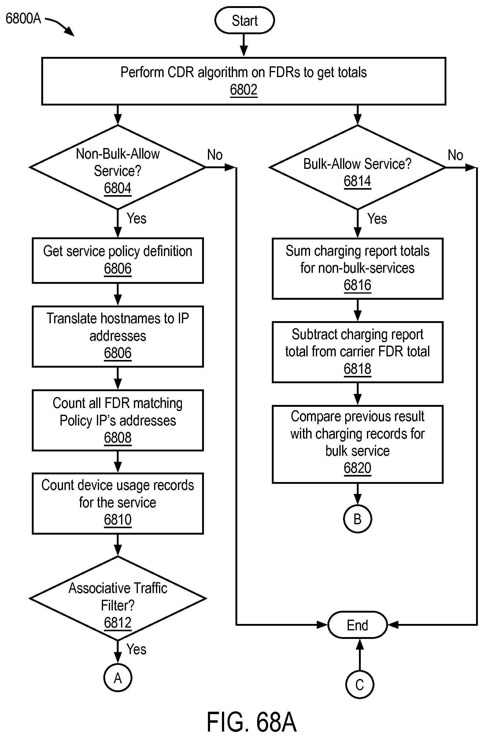
D00075
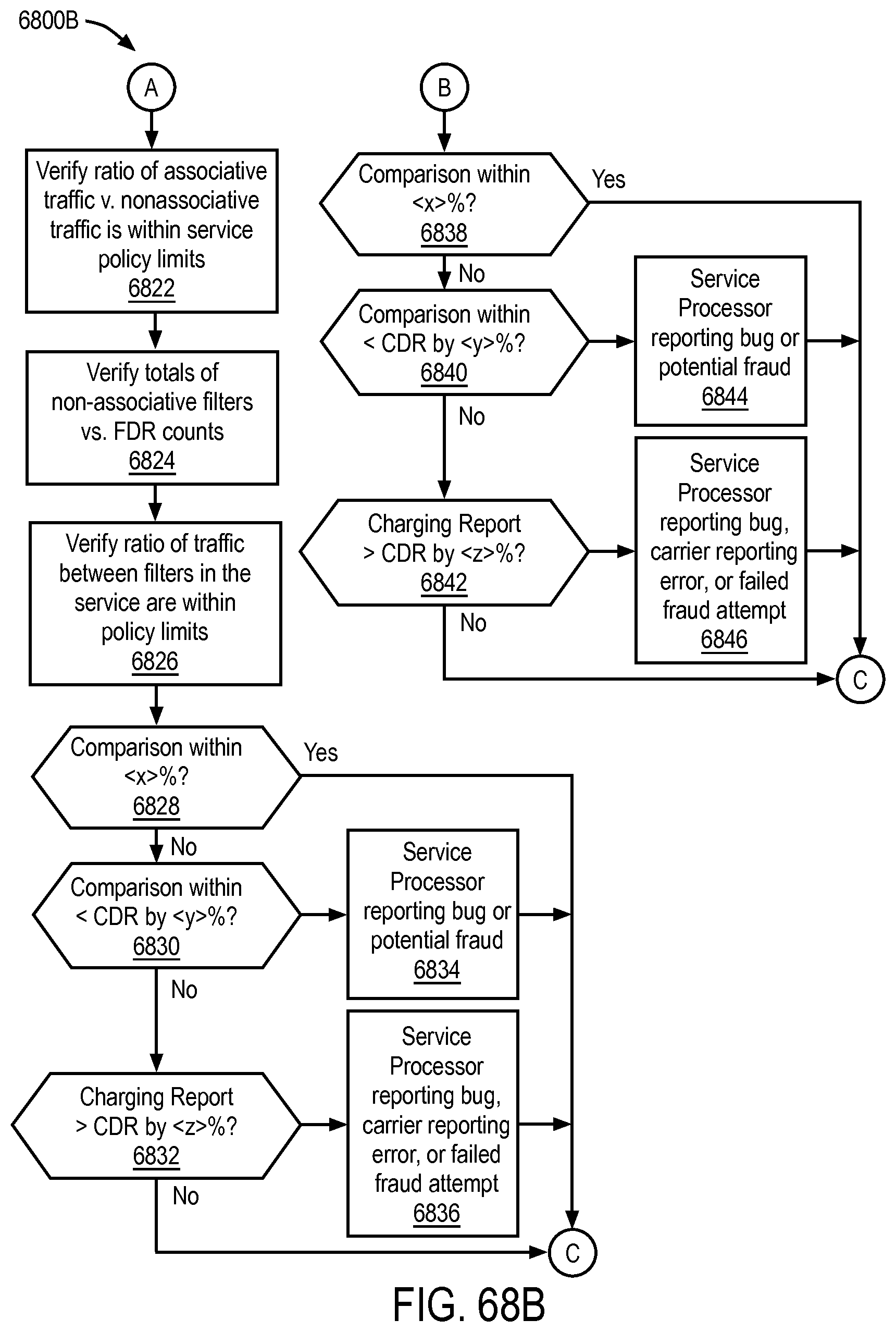
D00076
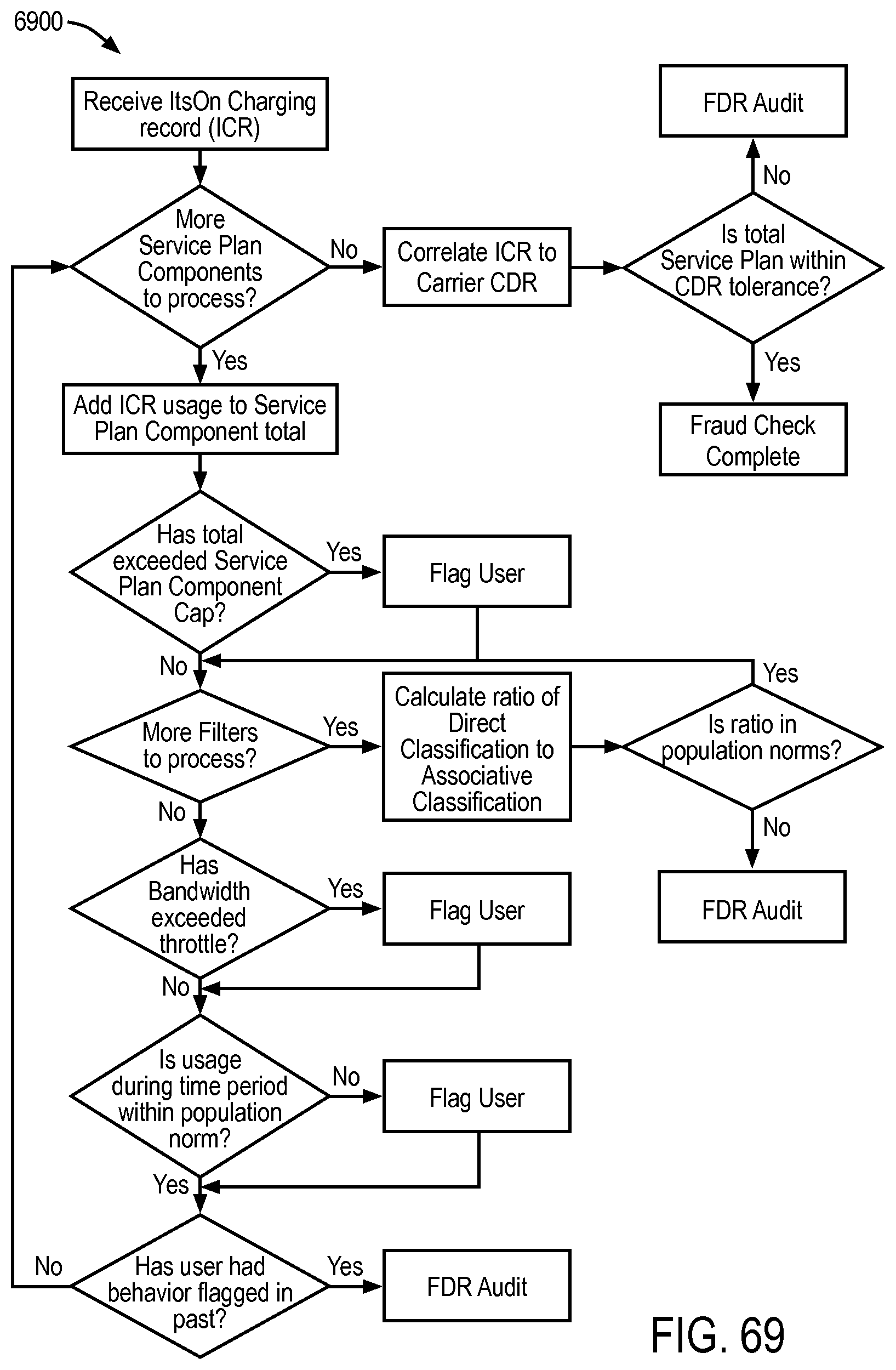
D00077
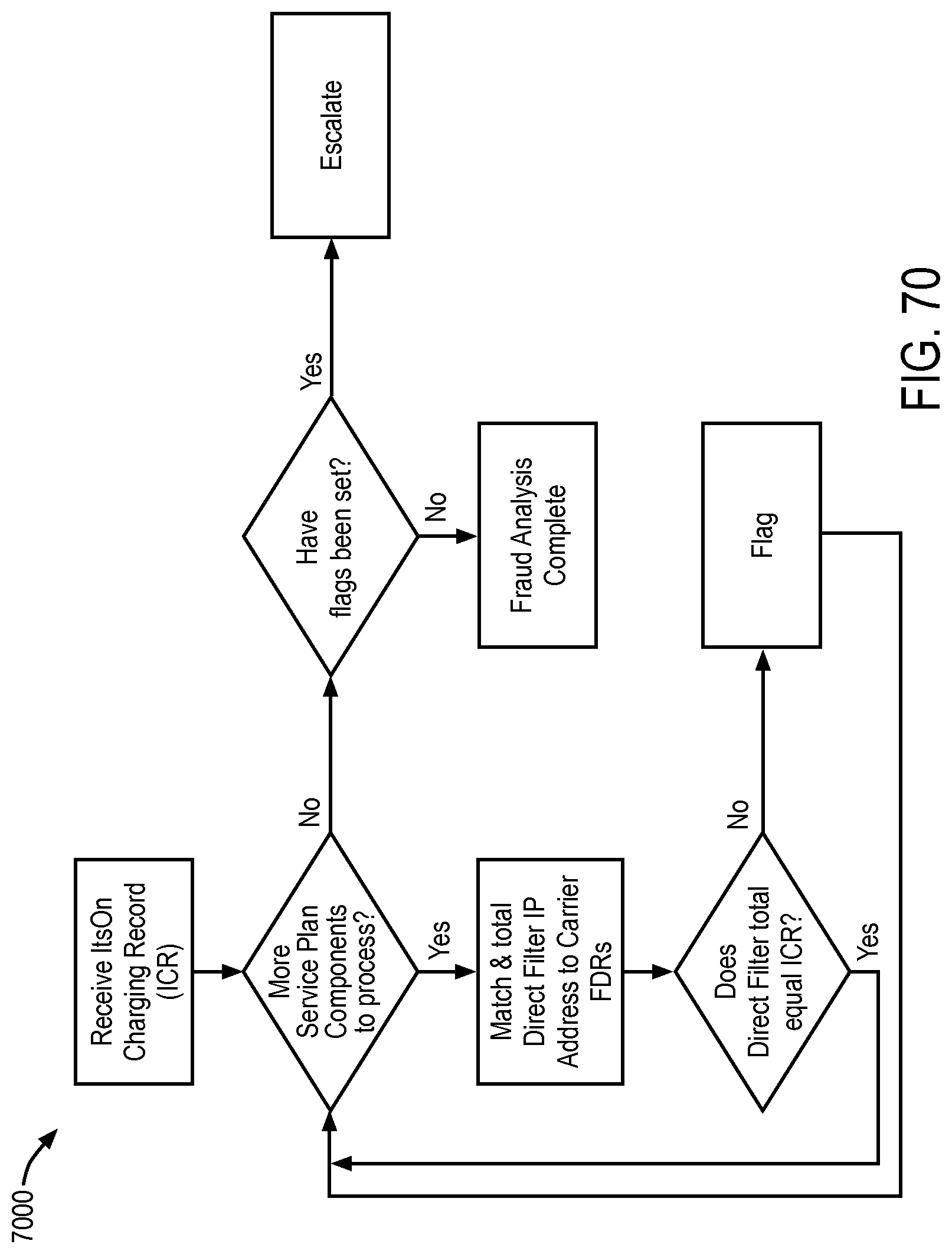
D00078

D00079
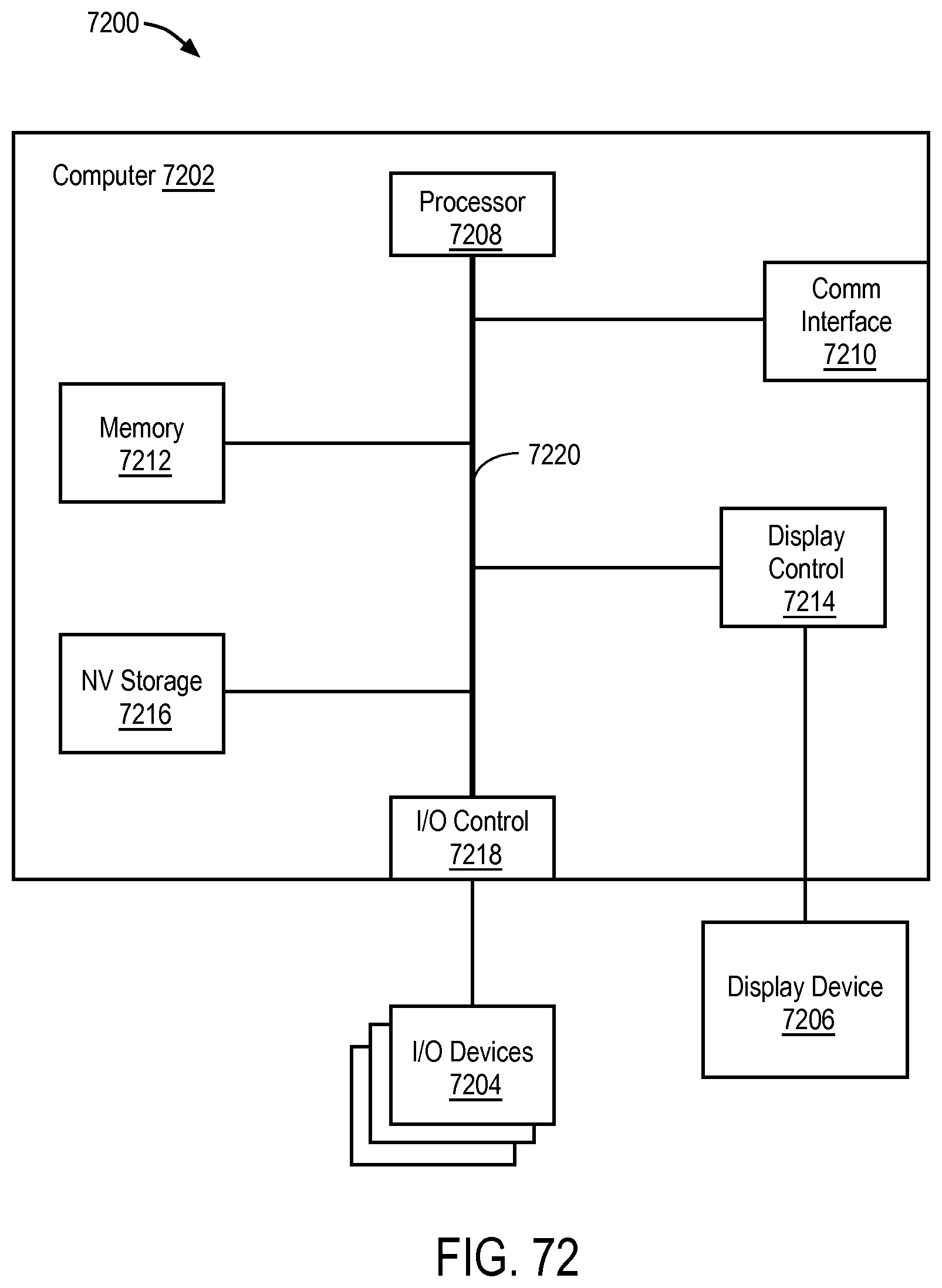
XML
uspto.report is an independent third-party trademark research tool that is not affiliated, endorsed, or sponsored by the United States Patent and Trademark Office (USPTO) or any other governmental organization. The information provided by uspto.report is based on publicly available data at the time of writing and is intended for informational purposes only.
While we strive to provide accurate and up-to-date information, we do not guarantee the accuracy, completeness, reliability, or suitability of the information displayed on this site. The use of this site is at your own risk. Any reliance you place on such information is therefore strictly at your own risk.
All official trademark data, including owner information, should be verified by visiting the official USPTO website at www.uspto.gov. This site is not intended to replace professional legal advice and should not be used as a substitute for consulting with a legal professional who is knowledgeable about trademark law.