Systems, methods, and devices for using a battery as an antenna for receiving wirelessly delivered power from radio frequency power waves
Hosseini , et al.
U.S. patent number 10,714,984 [Application Number 16/182,518] was granted by the patent office on 2020-07-14 for systems, methods, and devices for using a battery as an antenna for receiving wirelessly delivered power from radio frequency power waves. This patent grant is currently assigned to Energous Corporation. The grantee listed for this patent is Energous Corporation. Invention is credited to Alister Hosseini, Michael A. Leabman.


| United States Patent | 10,714,984 |
| Hosseini , et al. | July 14, 2020 |
Systems, methods, and devices for using a battery as an antenna for receiving wirelessly delivered power from radio frequency power waves
Abstract
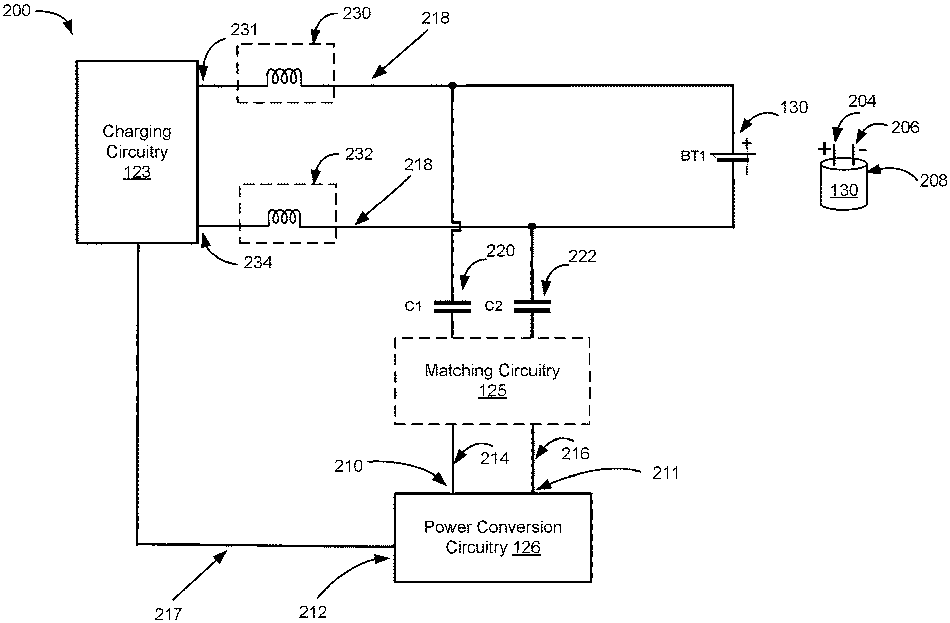
Methods of constructing a wireless power receiver that uses a battery as an antenna are provided. The method includes power conversion circuitry that has a connector, the first end connected to at least a part of a battery, and the part of the battery is configured to act as an antenna and receive radio frequency (RF) power signals. The second end of the connector is opposite to the first end and connected to the power conversion circuitry. The power conversion circuitry converts the RF power signals into a direct current (DC) voltage that is used to charge the battery. Additional, some methods for constructing a wireless power receiver include a different connector between the power conversion circuitry and charging circuitry. The charging circuitry is electrically coupled with at least the part of the battery via another connector and provides DC voltage to charge the battery.
| Inventors: | Hosseini; Alister (Phoenix, AZ), Leabman; Michael A. (San Ramon, CA) | ||||||||||
|---|---|---|---|---|---|---|---|---|---|---|---|
| Applicant: |
|
||||||||||
| Assignee: | Energous Corporation (San Jose,
CA) |
||||||||||
| Family ID: | 63963945 | ||||||||||
| Appl. No.: | 16/182,518 | ||||||||||
| Filed: | November 6, 2018 |
Prior Publication Data
| Document Identifier | Publication Date | |
|---|---|---|
| US 20190173323 A1 | Jun 6, 2019 | |
Related U.S. Patent Documents
| Application Number | Filing Date | Patent Number | Issue Date | ||
|---|---|---|---|---|---|
| 15952097 | Apr 12, 2018 | 10122219 | |||
| 15785324 | Oct 16, 2017 | ||||
| 62570542 | Oct 10, 2017 | ||||
| Current U.S. Class: | 1/1 |
| Current CPC Class: | H02J 7/0068 (20130101); H02J 7/00036 (20200101); H01M 10/425 (20130101); H02J 50/27 (20160201); H01M 10/44 (20130101); H01M 2010/4271 (20130101); H01M 2220/30 (20130101); H01M 2010/4278 (20130101) |
| Current International Class: | H02J 50/27 (20160101); H01M 10/44 (20060101); H02J 7/00 (20060101); H02J 7/02 (20160101); H01M 10/42 (20060101) |
| Field of Search: | ;307/2,104,151 |
References Cited [Referenced By]
U.S. Patent Documents
| 787412 | April 1905 | Tesla |
| 3167775 | January 1965 | Guertler |
| 3434678 | March 1969 | Brown et al. |
| 3696384 | October 1972 | Lester |
| 3754269 | August 1973 | Clavin |
| 4101895 | July 1978 | Jones, Jr. |
| 4360741 | November 1982 | Fitzsimmons et al. |
| 4944036 | July 1990 | Hyatt |
| 4995010 | February 1991 | Knight |
| 5200759 | April 1993 | McGinnis |
| 5211471 | May 1993 | Rohrs |
| 5548292 | August 1996 | Hirshfield et al. |
| 5556749 | September 1996 | Mitsuhashi et al. |
| 5568088 | October 1996 | Dent et al. |
| 5646633 | July 1997 | Dahlberg |
| 5697063 | December 1997 | Kishigami et al. |
| 5712642 | January 1998 | Hulderman |
| 5936527 | August 1999 | Isaacman et al. |
| 5982139 | November 1999 | Parise |
| 6046708 | April 2000 | MacDonald, Jr. et al. |
| 6127799 | October 2000 | Krishnan |
| 6127942 | October 2000 | Welle |
| 6163296 | December 2000 | Lier et al. |
| 6271799 | August 2001 | Rief |
| 6289237 | September 2001 | Mickle et al. |
| 6329908 | December 2001 | Frecska |
| 6400586 | June 2002 | Raddi et al. |
| 6421235 | July 2002 | Ditzik |
| 6437685 | August 2002 | Hanaki |
| 6456253 | September 2002 | Rummeli et al. |
| 6476795 | November 2002 | Derocher et al. |
| 6501414 | December 2002 | Amdt et al. |
| 6583723 | June 2003 | Watanabe et al. |
| 6597897 | July 2003 | Tang |
| 6615074 | September 2003 | Mickle et al. |
| 6650376 | November 2003 | Obitsu |
| 6664920 | December 2003 | Mott et al. |
| 6798716 | September 2004 | Charych |
| 6803744 | October 2004 | Sabo |
| 6853197 | February 2005 | McFarland |
| 6856291 | February 2005 | Mickle et al. |
| 6911945 | June 2005 | Korva |
| 6960968 | November 2005 | Odendaal et al. |
| 6967462 | November 2005 | Landis |
| 6988026 | January 2006 | Breed et al. |
| 7003350 | February 2006 | Denker et al. |
| 7027311 | April 2006 | Vanderelli et al. |
| 7068234 | June 2006 | Sievenpiper |
| 7068991 | June 2006 | Parise |
| 7079079 | July 2006 | JO et al. |
| 7183748 | February 2007 | Unno et al. |
| 7191013 | March 2007 | Miranda et al. |
| 7193644 | March 2007 | Carter |
| 7196663 | March 2007 | Bolzer et al. |
| 7205749 | April 2007 | Hagen et al. |
| 7215296 | May 2007 | Abramov et al. |
| 7222356 | May 2007 | Yonezawa et al. |
| 7274334 | September 2007 | o'Riordan et al. |
| 7274336 | September 2007 | Carson |
| 7351975 | April 2008 | Brady et al. |
| 7359730 | April 2008 | Dennis et al. |
| 7372408 | May 2008 | Gaucher |
| 7392068 | June 2008 | Dayan |
| 7403803 | July 2008 | Mickle et al. |
| 7443057 | October 2008 | Nunally |
| 7451839 | November 2008 | Perlman |
| 7463201 | December 2008 | Chiang et al. |
| 7471247 | December 2008 | Saily |
| 7535195 | May 2009 | Horovitz et al. |
| 7614556 | November 2009 | Overhultz et al. |
| 7639994 | December 2009 | Greene et al. |
| 7643312 | January 2010 | Vanderelli et al. |
| 7652577 | January 2010 | Madhow et al. |
| 7679576 | March 2010 | Riedel et al. |
| 7702771 | April 2010 | Ewing et al. |
| 7786419 | August 2010 | Hyde et al. |
| 7812771 | October 2010 | Greene et al. |
| 7830312 | November 2010 | Choudhury et al. |
| 7844306 | November 2010 | Shearer et al. |
| 7868482 | January 2011 | Greene et al. |
| 7898105 | March 2011 | Greene et al. |
| 7904117 | March 2011 | Doan et al. |
| 7911386 | March 2011 | Ito et al. |
| 7925308 | April 2011 | Greene et al. |
| 7948208 | May 2011 | Partovi et al. |
| 8055003 | November 2011 | Mittleman et al. |
| 8070595 | December 2011 | Alderucci et al. |
| 8072380 | December 2011 | Crouch |
| 8092301 | January 2012 | Alderucci et al. |
| 8099140 | January 2012 | Arai |
| 8115448 | February 2012 | John |
| 8159090 | April 2012 | Greene et al. |
| 8159364 | April 2012 | Zeine |
| 8180286 | May 2012 | Yamasuge |
| 8228194 | July 2012 | Mickle |
| 8234509 | July 2012 | Gioscia et al. |
| 8264101 | September 2012 | Hyde et al. |
| 8264291 | September 2012 | Morita |
| 8276325 | October 2012 | Clifton et al. |
| 8278784 | October 2012 | Cook et al. |
| 8284101 | October 2012 | Fusco |
| 8310201 | November 2012 | Wright |
| 8338991 | December 2012 | Von Novak et al. |
| 8362745 | January 2013 | Tinaphong |
| 8380255 | February 2013 | Shearer et al. |
| 8384600 | February 2013 | Huang et al. |
| 8410953 | April 2013 | Zeine |
| 8411963 | April 2013 | Luff |
| 8432062 | April 2013 | Greene et al. |
| 8432071 | April 2013 | Huang et al. |
| 8446248 | May 2013 | Zeine |
| 8447234 | May 2013 | Cook et al. |
| 8451189 | May 2013 | Fluhler |
| 8452235 | May 2013 | Kirby et al. |
| 8457656 | June 2013 | Perkins et al. |
| 8461817 | June 2013 | Martin et al. |
| 8467733 | June 2013 | Leabman |
| 8497601 | July 2013 | Hall et al. |
| 8497658 | July 2013 | Von Novak et al. |
| 8552597 | August 2013 | Song et al. |
| 8558661 | October 2013 | Zeine |
| 8560026 | October 2013 | Chanterac |
| 8604746 | December 2013 | Lee |
| 8614643 | December 2013 | Leabman |
| 8621245 | December 2013 | Shearer et al. |
| 8626249 | January 2014 | Kuusilinna et al. |
| 8629576 | January 2014 | Levine |
| 8653966 | February 2014 | Rao et al. |
| 8674551 | March 2014 | Low et al. |
| 8686685 | April 2014 | Moshfeghi |
| 8686905 | April 2014 | Shtrom |
| 8712355 | April 2014 | Black et al. |
| 8712485 | April 2014 | Tam |
| 8718773 | May 2014 | Wills et al. |
| 8729737 | May 2014 | Schatz et al. |
| 8736228 | May 2014 | Freed et al. |
| 8760113 | June 2014 | Keating |
| 8770482 | July 2014 | Ackermann et al. |
| 8772960 | July 2014 | Yoshida |
| 8823319 | September 2014 | Von Novak, III et al. |
| 8832646 | September 2014 | Wendling |
| 8854176 | October 2014 | Zeine |
| 8860364 | October 2014 | Low et al. |
| 8897770 | November 2014 | Frolov et al. |
| 8903456 | December 2014 | Chu et al. |
| 8917057 | December 2014 | Hui |
| 8923189 | December 2014 | Leabman |
| 8928544 | January 2015 | Massie et al. |
| 8937408 | January 2015 | Ganem et al. |
| 8946940 | February 2015 | Kim et al. |
| 8963486 | February 2015 | Kirby et al. |
| 8970070 | March 2015 | Sada et al. |
| 8989053 | March 2015 | Skaaksrud et al. |
| 9000616 | April 2015 | Greene et al. |
| 9001622 | April 2015 | Perry |
| 9006934 | April 2015 | Kozakai et al. |
| 9021277 | April 2015 | Shearer et al. |
| 9030161 | May 2015 | Lu et al. |
| 9059598 | June 2015 | Kang et al. |
| 9059599 | June 2015 | Won et al. |
| 9077188 | July 2015 | Moshfeghi |
| 9083595 | July 2015 | Rakib et al. |
| 9088216 | July 2015 | Garrity et al. |
| 9124125 | September 2015 | Leabman et al. |
| 9130397 | September 2015 | Leabman et al. |
| 9130602 | September 2015 | Cook |
| 9142998 | September 2015 | Yu et al. |
| 9143000 | September 2015 | Leabman et al. |
| 9143010 | September 2015 | Urano |
| 9153074 | October 2015 | Zhou et al. |
| 9178389 | November 2015 | Hwang |
| 9225196 | December 2015 | Huang et al. |
| 9240469 | January 2016 | Sun et al. |
| 9242411 | January 2016 | Kritchman et al. |
| 9244500 | January 2016 | Cain et al. |
| 9252628 | February 2016 | Leabman et al. |
| 9270344 | February 2016 | Rosenberg |
| 9282582 | March 2016 | Dunsbergen et al. |
| 9294840 | March 2016 | Anderson et al. |
| 9297896 | March 2016 | Andrews |
| 9318898 | April 2016 | John |
| 9368020 | June 2016 | Bell et al. |
| 9401977 | July 2016 | Gaw |
| 9409490 | August 2016 | Kawashima |
| 9419335 | August 2016 | Pintos |
| 9438045 | September 2016 | Leabman |
| 9438046 | September 2016 | Leabman |
| 9444283 | September 2016 | Son et al. |
| 9450449 | September 2016 | Leabman et al. |
| 9461502 | October 2016 | Lee et al. |
| 9520725 | December 2016 | Masaoka et al. |
| 9520748 | December 2016 | Hyde et al. |
| 9522270 | December 2016 | Perryman et al. |
| 9537354 | January 2017 | Bell et al. |
| 9537357 | January 2017 | Leabman |
| 9537358 | January 2017 | Leabman |
| 9538382 | January 2017 | Bell et al. |
| 9544640 | January 2017 | Lau |
| 9559553 | January 2017 | Bae |
| 9564773 | February 2017 | Pogorelik et al. |
| 9571974 | February 2017 | Choi et al. |
| 9590317 | March 2017 | Zimmerman et al. |
| 9590444 | March 2017 | Walley |
| 9620996 | April 2017 | Zeine |
| 9647328 | May 2017 | Dobric |
| 9706137 | July 2017 | Scanlon et al. |
| 9711999 | July 2017 | Hietala et al. |
| 9723635 | August 2017 | Nambord et al. |
| 9793758 | October 2017 | Leabman |
| 9793764 | October 2017 | Perry |
| 9800172 | October 2017 | Leabman |
| 9806564 | October 2017 | Leabman |
| 9819230 | November 2017 | Petras et al. |
| 9825674 | November 2017 | Leabman |
| 9843229 | December 2017 | Leabman |
| 9847669 | December 2017 | Leabman |
| 9847677 | December 2017 | Leabman |
| 9853361 | December 2017 | Chen et al. |
| 9853692 | December 2017 | Bell et al. |
| 9866279 | January 2018 | Bell et al. |
| 9867032 | January 2018 | Verma et al. |
| 9871301 | January 2018 | Contopanagos |
| 9876380 | January 2018 | Leabman et al. |
| 9876394 | January 2018 | Leabman |
| 9876536 | January 2018 | Bell et al. |
| 9882394 | January 2018 | Bell et al. |
| 9887584 | February 2018 | Bell et al. |
| 9893555 | February 2018 | Leabman et al. |
| 9899844 | February 2018 | Bell et al. |
| 9899861 | February 2018 | Leabman et al. |
| 9917477 | March 2018 | Bell et al. |
| 9923386 | March 2018 | Leabman et al. |
| 9939864 | April 2018 | Bell et al. |
| 9965009 | May 2018 | Bell et al. |
| 9966765 | May 2018 | Leabman |
| 9967743 | May 2018 | Bell et al. |
| 9973008 | May 2018 | Leabman |
| 10003211 | June 2018 | Leabman et al. |
| 10014728 | July 2018 | Leabman |
| 10038337 | July 2018 | Leabman et al. |
| 10050462 | August 2018 | Leabman et al. |
| 10056782 | August 2018 | Leabman |
| 10063064 | August 2018 | Bell et al. |
| 10068703 | September 2018 | Contopanagos |
| 10075008 | September 2018 | Bell et al. |
| 10090699 | October 2018 | Leabman |
| 10090886 | October 2018 | Bell et al. |
| 10122219 | November 2018 | Hosseini et al. |
| 10124754 | November 2018 | Leabman |
| 10128686 | November 2018 | Leabman et al. |
| 10134260 | November 2018 | Bell et al. |
| 10135112 | November 2018 | Hosseini |
| 10135294 | November 2018 | Leabman |
| 10141771 | November 2018 | Hosseini et al. |
| 10153645 | December 2018 | Bell et al. |
| 10153653 | December 2018 | Bell et al. |
| 10153660 | December 2018 | Leabman et al. |
| 10158259 | December 2018 | Leabman |
| 10164478 | December 2018 | Leabman |
| 10170917 | January 2019 | Bell et al. |
| 10186892 | January 2019 | Hosseini et al. |
| 10193396 | January 2019 | Bell et al. |
| 10199835 | February 2019 | Leabman |
| 10199849 | February 2019 | Bell |
| 10205239 | February 2019 | Contopanagos et al. |
| 10223717 | March 2019 | Bell |
| 10224982 | March 2019 | Leabman |
| 2001/0027876 | October 2001 | Tsukamoto et al. |
| 2002/0024471 | February 2002 | Ishitobi |
| 2002/0028655 | March 2002 | Rosener et al. |
| 2002/0034958 | March 2002 | Oberschmidt et al. |
| 2002/0072784 | June 2002 | Sheppard et al. |
| 2002/0103447 | August 2002 | Terry |
| 2002/0123776 | September 2002 | Von Arx |
| 2002/0133592 | September 2002 | Matsuda |
| 2002/0171594 | November 2002 | Fang |
| 2002/0172223 | November 2002 | Stilp |
| 2003/0005759 | January 2003 | Breed et al. |
| 2003/0058187 | March 2003 | Billiet et al. |
| 2003/0076274 | April 2003 | Phelan et al. |
| 2003/0179152 | September 2003 | Watada et al. |
| 2004/0036657 | February 2004 | Forster et al. |
| 2004/0066251 | April 2004 | Eleftheriades et al. |
| 2004/0107641 | June 2004 | Walton et al. |
| 2004/0130425 | July 2004 | Dayan et al. |
| 2004/0130442 | July 2004 | Breed |
| 2004/0142733 | July 2004 | Parise |
| 2004/0145342 | July 2004 | Lyon |
| 2004/0196190 | October 2004 | Mendolia et al. |
| 2004/0203979 | October 2004 | Attar et al. |
| 2004/0207559 | October 2004 | Milosavljevic |
| 2004/0259604 | December 2004 | Mickle et al. |
| 2004/0263124 | December 2004 | Wieck et al. |
| 2005/0007276 | January 2005 | Barrick et al. |
| 2005/0030118 | February 2005 | Wang |
| 2005/0046584 | March 2005 | Breed |
| 2005/0055316 | March 2005 | Williams |
| 2005/0077872 | April 2005 | Single |
| 2005/0093766 | May 2005 | Turner |
| 2005/0116683 | June 2005 | Cheng |
| 2005/0117660 | June 2005 | Vialle et al. |
| 2005/0134517 | June 2005 | Gottl |
| 2005/0171411 | August 2005 | KenKnight |
| 2005/0198673 | September 2005 | Kit et al. |
| 2005/0227619 | October 2005 | Lee et al. |
| 2005/0232469 | October 2005 | Schofield |
| 2005/0237249 | October 2005 | Nagel |
| 2005/0237258 | October 2005 | Abramov et al. |
| 2005/0282591 | December 2005 | Shaff |
| 2006/0013335 | January 2006 | Leabman |
| 2006/0019712 | January 2006 | Choi |
| 2006/0030279 | February 2006 | Leabman et al. |
| 2006/0033674 | February 2006 | Essig, Jr. et al. |
| 2006/0071308 | April 2006 | Tang et al. |
| 2006/0092079 | May 2006 | de Rochemont |
| 2006/0094425 | May 2006 | Mickle et al. |
| 2006/0113955 | June 2006 | Nunally |
| 2006/0119532 | June 2006 | Yun et al. |
| 2006/0136004 | June 2006 | Cowan et al. |
| 2006/0160517 | July 2006 | Yoon |
| 2006/0183473 | August 2006 | Ukon |
| 2006/0190063 | August 2006 | Kanzius |
| 2006/0192913 | August 2006 | Shutou et al. |
| 2006/0199620 | September 2006 | Greene et al. |
| 2006/0238365 | October 2006 | Vecchione et al. |
| 2006/0266564 | November 2006 | Perlman et al. |
| 2006/0266917 | November 2006 | Baldis et al. |
| 2006/0278706 | December 2006 | Hatakayama et al. |
| 2006/0284593 | December 2006 | Nagy et al. |
| 2006/0287094 | December 2006 | Mahaffey et al. |
| 2007/0007821 | January 2007 | Rossetti |
| 2007/0019693 | January 2007 | Graham |
| 2007/0021140 | January 2007 | Keyes |
| 2007/0060185 | March 2007 | Simon et al. |
| 2007/0070490 | March 2007 | Tsunoda et al. |
| 2007/0090997 | April 2007 | Brown et al. |
| 2007/0093269 | April 2007 | Leabman et al. |
| 2007/0097653 | May 2007 | Gilliland et al. |
| 2007/0103110 | May 2007 | Sagoo |
| 2007/0106894 | May 2007 | Zhang |
| 2007/0109121 | May 2007 | Cohen |
| 2007/0139000 | June 2007 | Kozuma |
| 2007/0149162 | June 2007 | Greene et al. |
| 2007/0164868 | July 2007 | Deavours et al. |
| 2007/0173196 | July 2007 | Gallic |
| 2007/0173214 | July 2007 | Mickle et al. |
| 2007/0178857 | August 2007 | Greene et al. |
| 2007/0178945 | August 2007 | Cook et al. |
| 2007/0182367 | August 2007 | Partovi |
| 2007/0191074 | August 2007 | Harrist et al. |
| 2007/0191075 | August 2007 | Greene et al. |
| 2007/0197281 | August 2007 | Stronach |
| 2007/0210960 | September 2007 | Rofougaran et al. |
| 2007/0222681 | September 2007 | Greene |
| 2007/0228833 | October 2007 | Stevens et al. |
| 2007/0257634 | November 2007 | Leschin et al. |
| 2007/0273486 | November 2007 | Shiotsu |
| 2007/0291165 | December 2007 | Wang |
| 2007/0296639 | December 2007 | Hook et al. |
| 2007/0298846 | December 2007 | Greene et al. |
| 2008/0014897 | January 2008 | Cook et al. |
| 2008/0024376 | January 2008 | Norris et al. |
| 2008/0048917 | February 2008 | Achour et al. |
| 2008/0062062 | March 2008 | Borau et al. |
| 2008/0062255 | March 2008 | Gal |
| 2008/0067874 | March 2008 | Tseng |
| 2008/0074324 | March 2008 | Puzella et al. |
| 2008/0089277 | April 2008 | Aledander et al. |
| 2008/0110263 | May 2008 | Klessel et al. |
| 2008/0113816 | May 2008 | Mahaffey et al. |
| 2008/0122297 | May 2008 | Arai |
| 2008/0123383 | May 2008 | Shionoiri |
| 2008/0129536 | June 2008 | Randall et al. |
| 2008/0140278 | June 2008 | Breed |
| 2008/0169910 | July 2008 | Greene et al. |
| 2008/0197802 | August 2008 | Onishi |
| 2008/0204342 | August 2008 | Kharadly |
| 2008/0204350 | August 2008 | Tam et al. |
| 2008/0210762 | September 2008 | Osada et al. |
| 2008/0211458 | September 2008 | Lawther et al. |
| 2008/0233890 | September 2008 | Baker |
| 2008/0248758 | October 2008 | Schedelbeck et al. |
| 2008/0248846 | October 2008 | Stronach et al. |
| 2008/0258993 | October 2008 | Gummalla et al. |
| 2008/0266191 | October 2008 | Hilgers |
| 2008/0278378 | November 2008 | Chang et al. |
| 2008/0309452 | December 2008 | Zeine |
| 2009/0002493 | January 2009 | Kates |
| 2009/0010316 | January 2009 | Rofougaran et al. |
| 2009/0019183 | January 2009 | Wu et al. |
| 2009/0036065 | February 2009 | Siu |
| 2009/0047998 | February 2009 | Alberth, Jr. |
| 2009/0058354 | March 2009 | Harrison |
| 2009/0058361 | March 2009 | John |
| 2009/0058731 | March 2009 | Geary et al. |
| 2009/0060012 | March 2009 | Gresset et al. |
| 2009/0067208 | March 2009 | Martin et al. |
| 2009/0073066 | March 2009 | Jordon et al. |
| 2009/0096412 | April 2009 | Huang |
| 2009/0096413 | April 2009 | Partovi |
| 2009/0102292 | April 2009 | Cook et al. |
| 2009/0102296 | April 2009 | Greene et al. |
| 2009/0108679 | April 2009 | Porwal |
| 2009/0122847 | May 2009 | Nysen et al. |
| 2009/0128262 | May 2009 | Lee et al. |
| 2009/0157911 | June 2009 | Aihara |
| 2009/0200985 | August 2009 | Zane et al. |
| 2009/0206791 | August 2009 | Jung |
| 2009/0207090 | August 2009 | Pettus et al. |
| 2009/0207092 | August 2009 | Nysen et al. |
| 2009/0218884 | September 2009 | Soar |
| 2009/0218891 | September 2009 | McCollough |
| 2009/0219903 | September 2009 | Alamouti et al. |
| 2009/0243397 | October 2009 | Cook et al. |
| 2009/0264069 | October 2009 | Yamasuge |
| 2009/0271048 | October 2009 | Wakamatsu |
| 2009/0280866 | November 2009 | Lo et al. |
| 2009/0281678 | November 2009 | Wakamatsu |
| 2009/0284082 | November 2009 | Mohammadian |
| 2009/0284083 | November 2009 | Karalis et al. |
| 2009/0284220 | November 2009 | Toncich et al. |
| 2009/0284227 | November 2009 | Mohammadian et al. |
| 2009/0284325 | November 2009 | Rossiter et al. |
| 2009/0286475 | November 2009 | Toncich et al. |
| 2009/0286476 | November 2009 | Toncich et al. |
| 2009/0291634 | November 2009 | Saarisalo |
| 2009/0299175 | December 2009 | Bernstein et al. |
| 2009/0308936 | December 2009 | Nitzan |
| 2009/0312046 | December 2009 | Clevenger et al. |
| 2009/0315412 | December 2009 | Yamamoto et al. |
| 2009/0322281 | December 2009 | Kamijo et al. |
| 2010/0001683 | January 2010 | Huang et al. |
| 2010/0007307 | January 2010 | Baarman et al. |
| 2010/0007569 | January 2010 | Sim et al. |
| 2010/0019686 | January 2010 | Gutierrez, Jr. |
| 2010/0019908 | January 2010 | Cho et al. |
| 2010/0026605 | February 2010 | Yang et al. |
| 2010/0027379 | February 2010 | Saulnier et al. |
| 2010/0029383 | February 2010 | Dai |
| 2010/0033021 | February 2010 | Bennett |
| 2010/0033390 | February 2010 | Alamouti et al. |
| 2010/0034238 | February 2010 | Bennett |
| 2010/0041453 | February 2010 | Grimm, Jr. |
| 2010/0044123 | February 2010 | Perlman et al. |
| 2010/0054200 | March 2010 | Tsai |
| 2010/0060534 | March 2010 | Oodachi |
| 2010/0066631 | March 2010 | Puzella et al. |
| 2010/0075607 | March 2010 | Hosoya |
| 2010/0079005 | April 2010 | Hyde et al. |
| 2010/0082193 | April 2010 | Chiappetta |
| 2010/0087227 | April 2010 | Francos et al. |
| 2010/0090524 | April 2010 | Obayashi |
| 2010/0090656 | April 2010 | Shearer et al. |
| 2010/0109443 | May 2010 | Cook et al. |
| 2010/0117926 | May 2010 | DeJean, II |
| 2010/0119234 | May 2010 | Suematsu et al. |
| 2010/0123618 | May 2010 | Martin et al. |
| 2010/0123624 | May 2010 | Minear et al. |
| 2010/0127660 | May 2010 | Cook et al. |
| 2010/0142418 | June 2010 | Nishioka et al. |
| 2010/0142509 | June 2010 | Zhu et al. |
| 2010/0148723 | June 2010 | Cook et al. |
| 2010/0151808 | June 2010 | Toncich et al. |
| 2010/0156721 | June 2010 | Alamouti et al. |
| 2010/0156741 | June 2010 | Vazquez et al. |
| 2010/0164296 | July 2010 | Kurs et al. |
| 2010/0164433 | July 2010 | Janefalker et al. |
| 2010/0171461 | July 2010 | Baarman et al. |
| 2010/0174629 | July 2010 | Taylor et al. |
| 2010/0176934 | July 2010 | Chou et al. |
| 2010/0181961 | July 2010 | Novak et al. |
| 2010/0181964 | July 2010 | Huggins et al. |
| 2010/0194206 | August 2010 | Burdo et al. |
| 2010/0201189 | August 2010 | Kirby et al. |
| 2010/0201201 | August 2010 | Mobarhan et al. |
| 2010/0201314 | August 2010 | Toncich et al. |
| 2010/0207572 | August 2010 | Kirby et al. |
| 2010/0210233 | August 2010 | Cook et al. |
| 2010/0213895 | August 2010 | Keating et al. |
| 2010/0214177 | August 2010 | Parsche |
| 2010/0222010 | September 2010 | Ozaki et al. |
| 2010/0225270 | September 2010 | Jacobs et al. |
| 2010/0227570 | September 2010 | Hendin |
| 2010/0231470 | September 2010 | Lee et al. |
| 2010/0237709 | September 2010 | Hall et al. |
| 2010/0244576 | September 2010 | Hillan et al. |
| 2010/0256831 | October 2010 | Abramo et al. |
| 2010/0259110 | October 2010 | Kurs et al. |
| 2010/0259447 | October 2010 | Crouch |
| 2010/0264747 | October 2010 | Hall et al. |
| 2010/0277003 | November 2010 | Von Novak et al. |
| 2010/0277121 | November 2010 | Hall et al. |
| 2010/0279606 | November 2010 | Hillan et al. |
| 2010/0289341 | November 2010 | Ozaki et al. |
| 2010/0295372 | November 2010 | Hyde et al. |
| 2010/0308767 | December 2010 | Rofougaran et al. |
| 2010/0309079 | December 2010 | Rofougaran et al. |
| 2010/0309088 | December 2010 | Hyvonen et al. |
| 2010/0315045 | December 2010 | Zeine |
| 2010/0316163 | December 2010 | Forenza et al. |
| 2010/0327766 | December 2010 | Recker et al. |
| 2010/0328044 | December 2010 | Waffenschmidt et al. |
| 2010/0332401 | December 2010 | Prahlad et al. |
| 2011/0013198 | January 2011 | Shirley |
| 2011/0018360 | January 2011 | Baarman et al. |
| 2011/0028114 | February 2011 | Kerselaers |
| 2011/0031928 | February 2011 | Soar |
| 2011/0032149 | February 2011 | Leabman |
| 2011/0032866 | February 2011 | Leabman |
| 2011/0034190 | February 2011 | Leabman |
| 2011/0034191 | February 2011 | Leabman |
| 2011/0043047 | February 2011 | Karalis et al. |
| 2011/0043163 | February 2011 | Baarman et al. |
| 2011/0043327 | February 2011 | Baarman et al. |
| 2011/0050166 | March 2011 | Cook et al. |
| 2011/0055037 | March 2011 | Hayashigawa et al. |
| 2011/0056215 | March 2011 | Ham |
| 2011/0057607 | March 2011 | Carobolante |
| 2011/0057853 | March 2011 | Kim et al. |
| 2011/0062788 | March 2011 | Chen et al. |
| 2011/0074342 | March 2011 | MacLaughlin |
| 2011/0074349 | March 2011 | Ghovanloo |
| 2011/0074620 | March 2011 | Wintermantel |
| 2011/0078092 | March 2011 | Kim et al. |
| 2011/0090126 | April 2011 | Szini et al. |
| 2011/0109167 | May 2011 | Park et al. |
| 2011/0114401 | May 2011 | Kanno et al. |
| 2011/0115303 | May 2011 | Baarman et al. |
| 2011/0115432 | May 2011 | El-Maleh |
| 2011/0115605 | May 2011 | Dimig et al. |
| 2011/0121660 | May 2011 | Azancot et al. |
| 2011/0122018 | May 2011 | Tarng et al. |
| 2011/0122026 | May 2011 | DeLaquil et al. |
| 2011/0127845 | June 2011 | Walley et al. |
| 2011/0127952 | June 2011 | Walley et al. |
| 2011/0133655 | June 2011 | Recker et al. |
| 2011/0133691 | June 2011 | Hautanen |
| 2011/0148578 | June 2011 | Aloi et al. |
| 2011/0148595 | June 2011 | Miller et al. |
| 2011/0151789 | June 2011 | Viglione et al. |
| 2011/0154429 | June 2011 | Stantchev |
| 2011/0156494 | June 2011 | Mashinsky |
| 2011/0156640 | June 2011 | Moshfeghi |
| 2011/0163128 | July 2011 | Taguchi et al. |
| 2011/0175455 | July 2011 | Hashiguchi |
| 2011/0175461 | July 2011 | Tinaphong |
| 2011/0181120 | July 2011 | Liu et al. |
| 2011/0182245 | July 2011 | Malkamaki et al. |
| 2011/0184842 | July 2011 | Melen |
| 2011/0188207 | August 2011 | Won et al. |
| 2011/0194543 | August 2011 | Zhao et al. |
| 2011/0195722 | August 2011 | Walter et al. |
| 2011/0199046 | August 2011 | Tsai et al. |
| 2011/0215086 | September 2011 | Yeh |
| 2011/0217923 | September 2011 | Ma |
| 2011/0220634 | September 2011 | Yeh |
| 2011/0221389 | September 2011 | Won et al. |
| 2011/0222272 | September 2011 | Yeh |
| 2011/0243040 | October 2011 | Khan et al. |
| 2011/0243050 | October 2011 | Yanover |
| 2011/0244913 | October 2011 | Kim et al. |
| 2011/0248573 | October 2011 | Kanno et al. |
| 2011/0248575 | October 2011 | Kim et al. |
| 2011/0249678 | October 2011 | Bonicatto |
| 2011/0254377 | October 2011 | Widmer et al. |
| 2011/0254503 | October 2011 | Widmer et al. |
| 2011/0259953 | October 2011 | Baarman et al. |
| 2011/0273977 | November 2011 | Shapira et al. |
| 2011/0278941 | November 2011 | Krishna et al. |
| 2011/0279226 | November 2011 | Chen et al. |
| 2011/0281535 | November 2011 | Low et al. |
| 2011/0282415 | November 2011 | Eckhoff et al. |
| 2011/0285213 | November 2011 | Kowalewski |
| 2011/0286374 | November 2011 | Shin et al. |
| 2011/0291489 | December 2011 | Tsai et al. |
| 2011/0302078 | December 2011 | Failing |
| 2011/0304216 | December 2011 | Baarman |
| 2011/0304437 | December 2011 | Beeler |
| 2011/0304521 | December 2011 | Ando et al. |
| 2012/0007441 | January 2012 | John |
| 2012/0013196 | January 2012 | Kim et al. |
| 2012/0013198 | January 2012 | Uramoto et al. |
| 2012/0013296 | January 2012 | Heydari et al. |
| 2012/0019419 | January 2012 | Prat et al. |
| 2012/0043887 | February 2012 | Mesibov |
| 2012/0051109 | March 2012 | Kim et al. |
| 2012/0051294 | March 2012 | Guillouard |
| 2012/0056486 | March 2012 | Endo et al. |
| 2012/0056741 | March 2012 | Zhu et al. |
| 2012/0068906 | March 2012 | Asher et al. |
| 2012/0074891 | March 2012 | Anderson et al. |
| 2012/0080944 | April 2012 | Recker et al. |
| 2012/0080957 | April 2012 | Cooper et al. |
| 2012/0086284 | April 2012 | Capanella et al. |
| 2012/0086615 | April 2012 | Norair |
| 2012/0095617 | April 2012 | Martin et al. |
| 2012/0098350 | April 2012 | Campanella et al. |
| 2012/0098485 | April 2012 | Kang et al. |
| 2012/0099675 | April 2012 | Kitamura et al. |
| 2012/0103562 | May 2012 | Clayton |
| 2012/0104849 | May 2012 | Jackson |
| 2012/0105252 | May 2012 | Wang |
| 2012/0112532 | May 2012 | Kesler et al. |
| 2012/0119914 | May 2012 | Uchida |
| 2012/0126743 | May 2012 | Rivers, Jr. |
| 2012/0132647 | May 2012 | Beverly et al. |
| 2012/0133214 | May 2012 | Yun et al. |
| 2012/0146426 | June 2012 | Sabo |
| 2012/0146576 | June 2012 | Partovi |
| 2012/0146577 | June 2012 | Tanabe |
| 2012/0147802 | June 2012 | Ukita et al. |
| 2012/0149307 | June 2012 | Terada et al. |
| 2012/0150670 | June 2012 | Taylor et al. |
| 2012/0153894 | June 2012 | Widmer et al. |
| 2012/0157019 | June 2012 | Li |
| 2012/0161531 | June 2012 | Kim et al. |
| 2012/0161544 | June 2012 | Kashiwagi et al. |
| 2012/0169276 | July 2012 | Wang |
| 2012/0169278 | July 2012 | Choi |
| 2012/0173418 | July 2012 | Beardsmore et al. |
| 2012/0179004 | July 2012 | Roesicke et al. |
| 2012/0181973 | July 2012 | Lyden |
| 2012/0182427 | July 2012 | Marshall |
| 2012/0187851 | August 2012 | Huggins et al. |
| 2012/0193999 | August 2012 | Zeine |
| 2012/0200399 | August 2012 | Chae |
| 2012/0201153 | August 2012 | Bharadia et al. |
| 2012/0201173 | August 2012 | Jian et al. |
| 2012/0206299 | August 2012 | Valdes-Garcia |
| 2012/0211214 | August 2012 | Phan |
| 2012/0212071 | August 2012 | Myabayashi et al. |
| 2012/0212072 | August 2012 | Miyabayashi et al. |
| 2012/0214462 | August 2012 | Chu et al. |
| 2012/0214536 | August 2012 | Kim et al. |
| 2012/0228392 | September 2012 | Cameron et al. |
| 2012/0228956 | September 2012 | Kamata |
| 2012/0231856 | September 2012 | Lee et al. |
| 2012/0235636 | September 2012 | Partovi |
| 2012/0242283 | September 2012 | Kim et al. |
| 2012/0248886 | October 2012 | Kesler et al. |
| 2012/0248888 | October 2012 | Kesler et al. |
| 2012/0248891 | October 2012 | Drennen |
| 2012/0249051 | October 2012 | Son et al. |
| 2012/0262002 | October 2012 | Widmer et al. |
| 2012/0265272 | October 2012 | Judkins |
| 2012/0267900 | October 2012 | Huffman et al. |
| 2012/0268238 | October 2012 | Park et al. |
| 2012/0274154 | November 2012 | DeLuca |
| 2012/0280650 | November 2012 | Kim et al. |
| 2012/0286582 | November 2012 | Kim et al. |
| 2012/0292993 | November 2012 | Mettler et al. |
| 2012/0293021 | November 2012 | Teggatz et al. |
| 2012/0293119 | November 2012 | Park et al. |
| 2012/0299389 | November 2012 | Lee et al. |
| 2012/0299540 | November 2012 | Perry |
| 2012/0299541 | November 2012 | Perry |
| 2012/0299542 | November 2012 | Perry |
| 2012/0300588 | November 2012 | Perry |
| 2012/0300592 | November 2012 | Perry |
| 2012/0300593 | November 2012 | Perry |
| 2012/0306705 | December 2012 | Sakurai et al. |
| 2012/0306707 | December 2012 | Yang et al. |
| 2012/0306720 | December 2012 | Tanmi et al. |
| 2012/0309295 | December 2012 | Maguire |
| 2012/0309308 | December 2012 | Kim et al. |
| 2012/0309332 | December 2012 | Liao |
| 2012/0313449 | December 2012 | Kurs |
| 2012/0313835 | December 2012 | Gebretnsae |
| 2012/0326660 | December 2012 | Lu et al. |
| 2013/0002550 | January 2013 | Zalewski |
| 2013/0018439 | January 2013 | Chow et al. |
| 2013/0024059 | January 2013 | Miller et al. |
| 2013/0026981 | January 2013 | Van Der Lee |
| 2013/0026982 | January 2013 | Rothenbaum |
| 2013/0032589 | February 2013 | Chung |
| 2013/0033571 | February 2013 | Steen |
| 2013/0038124 | February 2013 | Newdoll et al. |
| 2013/0038402 | February 2013 | Karalis et al. |
| 2013/0043738 | February 2013 | Park et al. |
| 2013/0044035 | February 2013 | Zhuang |
| 2013/0049471 | February 2013 | Oleynik |
| 2013/0049475 | February 2013 | Kim et al. |
| 2013/0049484 | February 2013 | Weissentern et al. |
| 2013/0057078 | March 2013 | Lee |
| 2013/0057205 | March 2013 | Lee et al. |
| 2013/0057210 | March 2013 | Negaard et al. |
| 2013/0057364 | March 2013 | Kesler et al. |
| 2013/0058379 | March 2013 | Kim et al. |
| 2013/0063082 | March 2013 | Lee et al. |
| 2013/0063143 | March 2013 | Adalsteinsson et al. |
| 2013/0069444 | March 2013 | Waffenschmidt et al. |
| 2013/0077650 | March 2013 | Traxler et al. |
| 2013/0078918 | March 2013 | Crowley et al. |
| 2013/0082651 | April 2013 | Park et al. |
| 2013/0082653 | April 2013 | Lee et al. |
| 2013/0083774 | April 2013 | Son et al. |
| 2013/0088082 | April 2013 | Kang et al. |
| 2013/0088090 | April 2013 | Wu |
| 2013/0088192 | April 2013 | Eaton |
| 2013/0088331 | April 2013 | Cho |
| 2013/0093388 | April 2013 | Partovi |
| 2013/0099389 | April 2013 | Hong et al. |
| 2013/0099586 | April 2013 | Kato |
| 2013/0106197 | May 2013 | Bae et al. |
| 2013/0107023 | May 2013 | Tanaka et al. |
| 2013/0119777 | May 2013 | Rees |
| 2013/0119778 | May 2013 | Jung |
| 2013/0119929 | May 2013 | Partovi |
| 2013/0120217 | May 2013 | Ueda et al. |
| 2013/0132010 | May 2013 | Winger et al. |
| 2013/0134923 | May 2013 | Smith |
| 2013/0137455 | May 2013 | Xia |
| 2013/0141037 | June 2013 | Jenwatanavet et al. |
| 2013/0148341 | June 2013 | Williams |
| 2013/0149975 | June 2013 | Yu et al. |
| 2013/0154387 | June 2013 | Lee et al. |
| 2013/0155748 | June 2013 | Sundstrom |
| 2013/0157729 | June 2013 | Tabe |
| 2013/0162335 | June 2013 | Kim et al. |
| 2013/0169061 | July 2013 | Microshnichenko et al. |
| 2013/0169219 | July 2013 | Gray |
| 2013/0169348 | July 2013 | Shi |
| 2013/0171939 | July 2013 | Tian et al. |
| 2013/0175877 | July 2013 | Abe et al. |
| 2013/0178253 | July 2013 | Karaoguz |
| 2013/0181881 | July 2013 | Christie et al. |
| 2013/0187475 | July 2013 | Vendik |
| 2013/0190031 | July 2013 | Persson et al. |
| 2013/0193769 | August 2013 | Mehta et al. |
| 2013/0197320 | August 2013 | Albert et al. |
| 2013/0200064 | August 2013 | Alexander |
| 2013/0207477 | August 2013 | Nam et al. |
| 2013/0207604 | August 2013 | Zeine |
| 2013/0207879 | August 2013 | Rada et al. |
| 2013/0210357 | August 2013 | Qin et al. |
| 2013/0221757 | August 2013 | Cho et al. |
| 2013/0222201 | August 2013 | Ma et al. |
| 2013/0234530 | September 2013 | Miyauchi |
| 2013/0234536 | September 2013 | Chemishkian et al. |
| 2013/0234658 | September 2013 | Endo et al. |
| 2013/0241306 | September 2013 | Aber et al. |
| 2013/0241468 | September 2013 | Moshfeghi |
| 2013/0241474 | September 2013 | Moshfeghi |
| 2013/0249478 | September 2013 | Hirano |
| 2013/0249479 | September 2013 | Partovi |
| 2013/0250102 | September 2013 | Scanlon et al. |
| 2013/0254578 | September 2013 | Huang et al. |
| 2013/0264997 | October 2013 | Lee et al. |
| 2013/0268782 | October 2013 | Tam et al. |
| 2013/0270923 | October 2013 | Cook et al. |
| 2013/0278076 | October 2013 | Proud |
| 2013/0278209 | October 2013 | Von Novak |
| 2013/0285464 | October 2013 | Miwa |
| 2013/0285477 | October 2013 | Lo et al. |
| 2013/0285606 | October 2013 | Ben-Shalom et al. |
| 2013/0288600 | October 2013 | Kuusilinna et al. |
| 2013/0288617 | October 2013 | Kim et al. |
| 2013/0293423 | November 2013 | Moshfeghi |
| 2013/0307751 | November 2013 | Yu-Juin et al. |
| 2013/0310020 | November 2013 | Kazuhiro |
| 2013/0311798 | November 2013 | Sultenfuss |
| 2013/0328417 | December 2013 | Takeuchi |
| 2013/0334883 | December 2013 | Kim et al. |
| 2013/0339108 | December 2013 | Ryder et al. |
| 2013/0343208 | December 2013 | Sexton et al. |
| 2013/0343251 | December 2013 | Zhang |
| 2014/0001846 | January 2014 | Mosebrook |
| 2014/0001875 | January 2014 | Nahidipour |
| 2014/0001876 | January 2014 | Fujiwara et al. |
| 2014/0006017 | January 2014 | Sen |
| 2014/0008992 | January 2014 | Leabman |
| 2014/0008993 | January 2014 | Leabman |
| 2014/0009108 | January 2014 | Leabman |
| 2014/0009110 | January 2014 | Lee |
| 2014/0011531 | January 2014 | Burstrom et al. |
| 2014/0015336 | January 2014 | Weber et al. |
| 2014/0015344 | January 2014 | Mohamadi |
| 2014/0021907 | January 2014 | Yu et al. |
| 2014/0021908 | January 2014 | McCool |
| 2014/0035524 | February 2014 | Zeine |
| 2014/0035526 | February 2014 | Tripathi et al. |
| 2014/0035786 | February 2014 | Ley |
| 2014/0043248 | February 2014 | Yeh |
| 2014/0049422 | February 2014 | Von Novak et al. |
| 2014/0054971 | February 2014 | Kissin |
| 2014/0055098 | February 2014 | Lee et al. |
| 2014/0057618 | February 2014 | Zirwas et al. |
| 2014/0062395 | March 2014 | Kwon et al. |
| 2014/0082435 | March 2014 | Kitgawa |
| 2014/0086125 | March 2014 | Polo et al. |
| 2014/0086592 | March 2014 | Nakahara et al. |
| 2014/0091756 | April 2014 | Ofstein et al. |
| 2014/0091968 | April 2014 | Harel et al. |
| 2014/0091974 | April 2014 | Desclos et al. |
| 2014/0103869 | April 2014 | Radovic |
| 2014/0111147 | April 2014 | Soar |
| 2014/0113689 | April 2014 | Lee |
| 2014/0117946 | May 2014 | Muller et al. |
| 2014/0118140 | May 2014 | Amis |
| 2014/0128107 | May 2014 | An |
| 2014/0132210 | May 2014 | Partovi |
| 2014/0133279 | May 2014 | Khuri-Yakub |
| 2014/0139034 | May 2014 | Sankar et al. |
| 2014/0139039 | May 2014 | Cook et al. |
| 2014/0139180 | May 2014 | Kim et al. |
| 2014/0141838 | May 2014 | Cai et al. |
| 2014/0142876 | May 2014 | John et al. |
| 2014/0143933 | May 2014 | Low et al. |
| 2014/0145879 | May 2014 | Pan |
| 2014/0145884 | May 2014 | Dang et al. |
| 2014/0152117 | June 2014 | Sanker |
| 2014/0159651 | June 2014 | Von Novak et al. |
| 2014/0159652 | June 2014 | Hall et al. |
| 2014/0159662 | June 2014 | Furui |
| 2014/0159667 | June 2014 | Kim et al. |
| 2014/0169385 | June 2014 | Hadani et al. |
| 2014/0175893 | June 2014 | Sengupta et al. |
| 2014/0176054 | June 2014 | Porat et al. |
| 2014/0176061 | June 2014 | Cheatham, III et al. |
| 2014/0177399 | June 2014 | Teng et al. |
| 2014/0184148 | July 2014 | Van Der Lee et al. |
| 2014/0184155 | July 2014 | Cha |
| 2014/0184163 | July 2014 | Das et al. |
| 2014/0184170 | July 2014 | Jeong |
| 2014/0191568 | July 2014 | Partovi |
| 2014/0194092 | July 2014 | Wanstedt et al. |
| 2014/0194095 | July 2014 | Wanstedt et al. |
| 2014/0197691 | July 2014 | Wang |
| 2014/0206384 | July 2014 | Kim et al. |
| 2014/0210281 | July 2014 | Ito et al. |
| 2014/0217955 | August 2014 | Lin |
| 2014/0217967 | August 2014 | Zeine et al. |
| 2014/0225805 | August 2014 | Pan et al. |
| 2014/0232320 | August 2014 | Ento July et al. |
| 2014/0232610 | August 2014 | Shigemoto et al. |
| 2014/0239733 | August 2014 | Mach et al. |
| 2014/0241231 | August 2014 | Zeine |
| 2014/0245036 | August 2014 | Oishi |
| 2014/0246416 | September 2014 | White |
| 2014/0247152 | September 2014 | Proud |
| 2014/0252813 | September 2014 | Lee et al. |
| 2014/0252866 | September 2014 | Walsh et al. |
| 2014/0265725 | September 2014 | Angle et al. |
| 2014/0265727 | September 2014 | Berte |
| 2014/0265943 | September 2014 | Angle et al. |
| 2014/0266025 | September 2014 | Jakubowski |
| 2014/0266946 | September 2014 | Bily et al. |
| 2014/0273892 | September 2014 | Nourbakhsh |
| 2014/0281655 | September 2014 | Angle et al. |
| 2014/0300452 | October 2014 | Rofe et al. |
| 2014/0312706 | October 2014 | Fiorello et al. |
| 2014/0325218 | October 2014 | Shimizu et al. |
| 2014/0327320 | November 2014 | Muhs et al. |
| 2014/0327390 | November 2014 | Park et al. |
| 2014/0333142 | November 2014 | Desrosiers |
| 2014/0346860 | November 2014 | Aubry et al. |
| 2014/0354063 | December 2014 | Leabman et al. |
| 2014/0354221 | December 2014 | Leabman et al. |
| 2014/0355718 | December 2014 | Guan et al. |
| 2014/0357309 | December 2014 | Leabman et al. |
| 2014/0368048 | December 2014 | Leabman |
| 2014/0368161 | December 2014 | Leabman et al. |
| 2014/0368405 | December 2014 | EK et al. |
| 2014/0375139 | December 2014 | Tsukamoto |
| 2014/0375253 | December 2014 | Leabman et al. |
| 2014/0375255 | December 2014 | Leabman et al. |
| 2014/0375258 | December 2014 | Arkhipenkov |
| 2014/0375261 | December 2014 | Manova-Elssibony et al. |
| 2014/0376646 | December 2014 | Leabman et al. |
| 2015/0001949 | January 2015 | Leabman et al. |
| 2015/0002086 | January 2015 | Matos et al. |
| 2015/0003207 | January 2015 | Lee et al. |
| 2015/0008980 | January 2015 | Kim et al. |
| 2015/0011160 | January 2015 | Uurgovan et al. |
| 2015/0015180 | January 2015 | Miller et al. |
| 2015/0015182 | January 2015 | Brandtman et al. |
| 2015/0015192 | January 2015 | Leabamn |
| 2015/0015194 | January 2015 | Leabman et al. |
| 2015/0015195 | January 2015 | Leabman et al. |
| 2015/0021990 | January 2015 | Myer et al. |
| 2015/0022008 | January 2015 | Leabman et al. |
| 2015/0022009 | January 2015 | Leabman et al. |
| 2015/0022010 | January 2015 | Leabman et al. |
| 2015/0023204 | January 2015 | Wil et al. |
| 2015/0028688 | January 2015 | Masaoka |
| 2015/0028694 | January 2015 | Leabman et al. |
| 2015/0028697 | January 2015 | Leabman et al. |
| 2015/0028875 | January 2015 | Irie et al. |
| 2015/0029397 | January 2015 | Leabman et al. |
| 2015/0035378 | February 2015 | Calhoun et al. |
| 2015/0035715 | February 2015 | Kim et al. |
| 2015/0039482 | February 2015 | Fuinaga |
| 2015/0041459 | February 2015 | Leabman et al. |
| 2015/0042264 | February 2015 | Leabman et al. |
| 2015/0042265 | February 2015 | Leabman et al. |
| 2015/0044977 | February 2015 | Ramasamy et al. |
| 2015/0046526 | February 2015 | Bush et al. |
| 2015/0061404 | March 2015 | Lamenza et al. |
| 2015/0076917 | March 2015 | Leabman et al. |
| 2015/0076927 | March 2015 | Leabman et al. |
| 2015/0077036 | March 2015 | Leabman et al. |
| 2015/0077037 | March 2015 | Leabman et al. |
| 2015/0091520 | April 2015 | Blum et al. |
| 2015/0091706 | April 2015 | Chemishkian et al. |
| 2015/0097663 | April 2015 | Sloo et al. |
| 2015/0102681 | April 2015 | Leabman et al. |
| 2015/0102764 | April 2015 | Leabman et al. |
| 2015/0102769 | April 2015 | Leabman et al. |
| 2015/0102973 | April 2015 | Hand et al. |
| 2015/0108848 | April 2015 | Joehren |
| 2015/0109181 | April 2015 | Hyde et al. |
| 2015/0115877 | April 2015 | Aria et al. |
| 2015/0115878 | April 2015 | Park |
| 2015/0123483 | May 2015 | Leabman et al. |
| 2015/0123496 | May 2015 | Leabman et al. |
| 2015/0128733 | May 2015 | Taylor et al. |
| 2015/0130285 | May 2015 | Leabman et al. |
| 2015/0130293 | May 2015 | Hajimiri et al. |
| 2015/0148664 | May 2015 | Stolka et al. |
| 2015/0155737 | June 2015 | Mayo |
| 2015/0155738 | June 2015 | Leabman et al. |
| 2015/0162751 | June 2015 | Leabman et al. |
| 2015/0162779 | June 2015 | Lee et al. |
| 2015/0171513 | June 2015 | Chen et al. |
| 2015/0171656 | June 2015 | Leabman et al. |
| 2015/0171658 | June 2015 | Manova-Elssibony et al. |
| 2015/0171931 | June 2015 | Won et al. |
| 2015/0177326 | June 2015 | Chakraborty et al. |
| 2015/0180133 | June 2015 | Hunt |
| 2015/0180249 | June 2015 | Jeon et al. |
| 2015/0181117 | June 2015 | Park et al. |
| 2015/0187491 | July 2015 | Yanagawa |
| 2015/0188352 | July 2015 | Peek et al. |
| 2015/0199665 | July 2015 | Chu |
| 2015/0207333 | July 2015 | Baarman et al. |
| 2015/0207542 | July 2015 | Zeine |
| 2015/0222126 | August 2015 | Leabman et al. |
| 2015/0233987 | August 2015 | Von Novak, III et al. |
| 2015/0234144 | August 2015 | Cameron et al. |
| 2015/0236520 | August 2015 | Baarman |
| 2015/0244070 | August 2015 | Cheng et al. |
| 2015/0244080 | August 2015 | Gregoire |
| 2015/0244187 | August 2015 | Horie |
| 2015/0244201 | August 2015 | Chu |
| 2015/0244341 | August 2015 | Ritter et al. |
| 2015/0249484 | September 2015 | Mach et al. |
| 2015/0255989 | September 2015 | Walley et al. |
| 2015/0256097 | September 2015 | Gudan et al. |
| 2015/0263534 | September 2015 | Lee et al. |
| 2015/0263548 | September 2015 | Cooper |
| 2015/0270618 | September 2015 | Zhu et al. |
| 2015/0270741 | September 2015 | Leabman et al. |
| 2015/0280484 | October 2015 | Radziemski et al. |
| 2015/0288074 | October 2015 | Harper et al. |
| 2015/0288438 | October 2015 | Maltsev et al. |
| 2015/0311585 | October 2015 | Church et al. |
| 2015/0312721 | October 2015 | Singh |
| 2015/0318729 | November 2015 | Leabman |
| 2015/0326024 | November 2015 | Bell et al. |
| 2015/0326025 | November 2015 | Bell et al. |
| 2015/0326063 | November 2015 | Leabman et al. |
| 2015/0326068 | November 2015 | Bell et al. |
| 2015/0326069 | November 2015 | Petras et al. |
| 2015/0326070 | November 2015 | Petras et al. |
| 2015/0326072 | November 2015 | Petras et al. |
| 2015/0326142 | November 2015 | Petras et al. |
| 2015/0326143 | November 2015 | Petras et al. |
| 2015/0327085 | November 2015 | Hadani |
| 2015/0333528 | November 2015 | Leabman |
| 2015/0333529 | November 2015 | Leabman |
| 2015/0333573 | November 2015 | Leabman |
| 2015/0333800 | November 2015 | Perry et al. |
| 2015/0340759 | November 2015 | Bridgelall et al. |
| 2015/0340903 | November 2015 | Bell et al. |
| 2015/0340909 | November 2015 | Bell et al. |
| 2015/0340910 | November 2015 | Petras et al. |
| 2015/0340911 | November 2015 | Bell et al. |
| 2015/0341087 | November 2015 | Moore et al. |
| 2015/0349574 | December 2015 | Leabman |
| 2015/0358222 | December 2015 | Berger et al. |
| 2015/0365137 | December 2015 | Miller et al. |
| 2015/0365138 | December 2015 | Miller et al. |
| 2016/0005068 | January 2016 | IM et al. |
| 2016/0012695 | January 2016 | Bell et al. |
| 2016/0013656 | January 2016 | Bell et al. |
| 2016/0013677 | January 2016 | Bell et al. |
| 2016/0013678 | January 2016 | Bell et al. |
| 2016/0013855 | January 2016 | Campos |
| 2016/0020636 | January 2016 | Khlat |
| 2016/0020647 | January 2016 | Leabman et al. |
| 2016/0020649 | January 2016 | Bell et al. |
| 2016/0020830 | January 2016 | Bell et al. |
| 2016/0042206 | February 2016 | Pesavento et al. |
| 2016/0054395 | February 2016 | Bell et al. |
| 2016/0054396 | February 2016 | Bell et al. |
| 2016/0054440 | February 2016 | Younis |
| 2016/0056635 | February 2016 | Bell |
| 2016/0056640 | February 2016 | Mao |
| 2016/0056669 | February 2016 | Bell |
| 2016/0056966 | February 2016 | Bell |
| 2016/0065005 | March 2016 | Won et al. |
| 2016/0079799 | March 2016 | Khlat |
| 2016/0087483 | March 2016 | Hietala et al. |
| 2016/0087486 | March 2016 | Pogorelik et al. |
| 2016/0094091 | March 2016 | Shin et al. |
| 2016/0094092 | March 2016 | Davlantes et al. |
| 2016/0099601 | April 2016 | Leabman et al. |
| 2016/0099602 | April 2016 | Leabman et al. |
| 2016/0099609 | April 2016 | Leabman et al. |
| 2016/0099610 | April 2016 | Leabman et al. |
| 2016/0099611 | April 2016 | Leabman et al. |
| 2016/0099612 | April 2016 | Leabman et al. |
| 2016/0099613 | April 2016 | Leabman et al. |
| 2016/0099614 | April 2016 | Leabman et al. |
| 2016/0099755 | April 2016 | Leabman et al. |
| 2016/0099756 | April 2016 | Leabman et al. |
| 2016/0099757 | April 2016 | Leabman et al. |
| 2016/0099758 | April 2016 | Leabman et al. |
| 2016/0100124 | April 2016 | Leabman et al. |
| 2016/0100312 | April 2016 | Bell et al. |
| 2016/0112787 | April 2016 | Rich |
| 2016/0126752 | May 2016 | Vuori et al. |
| 2016/0126776 | May 2016 | Kim et al. |
| 2016/0141908 | May 2016 | Jakl et al. |
| 2016/0164563 | June 2016 | Khawand et al. |
| 2016/0181849 | June 2016 | Govindaraj |
| 2016/0181854 | June 2016 | Leabman |
| 2016/0181867 | June 2016 | Daniel et al. |
| 2016/0181873 | June 2016 | Mitcheson et al. |
| 2016/0191121 | June 2016 | Bell |
| 2016/0202343 | July 2016 | Okutsu |
| 2016/0204622 | July 2016 | Leabman |
| 2016/0204642 | July 2016 | Oh |
| 2016/0238365 | August 2016 | Wixey et al. |
| 2016/0240908 | August 2016 | Strong |
| 2016/0294225 | October 2016 | Blum et al. |
| 2016/0299210 | October 2016 | Zeine |
| 2016/0323000 | November 2016 | Liu et al. |
| 2016/0336804 | November 2016 | Son et al. |
| 2016/0339258 | November 2016 | Perryman et al. |
| 2016/0359367 | December 2016 | Rothschild |
| 2016/0380464 | December 2016 | Chin et al. |
| 2017/0005481 | January 2017 | Von Novak, III |
| 2017/0005516 | January 2017 | Leabman et al. |
| 2017/0005524 | January 2017 | Akuzawa et al. |
| 2017/0005530 | January 2017 | Zeine et al. |
| 2017/0025903 | January 2017 | Song et al. |
| 2017/0026087 | January 2017 | Tanabe |
| 2017/0040700 | February 2017 | Leung |
| 2017/0043675 | February 2017 | Jones et al. |
| 2017/0047784 | February 2017 | Jung et al. |
| 2017/0187225 | February 2017 | Hosseini |
| 2017/0063168 | March 2017 | Uchida |
| 2017/0077733 | March 2017 | Jeong et al. |
| 2017/0077735 | March 2017 | Leabman |
| 2017/0077736 | March 2017 | Leabman |
| 2017/0077764 | March 2017 | Bell et al. |
| 2017/0077765 | March 2017 | Bell et al. |
| 2017/0077995 | March 2017 | Leabman |
| 2017/0085112 | March 2017 | Leabman et al. |
| 2017/0085120 | March 2017 | Leabman et al. |
| 2017/0085127 | March 2017 | Leabman |
| 2017/0085437 | March 2017 | Condeixa et al. |
| 2017/0092115 | March 2017 | Sloo et al. |
| 2017/0104263 | April 2017 | Hosseini |
| 2017/0110887 | April 2017 | Bell et al. |
| 2017/0110888 | April 2017 | Leabman |
| 2017/0110889 | April 2017 | Bell |
| 2017/0110914 | April 2017 | Bell |
| 2017/0127196 | May 2017 | Blum et al. |
| 2017/0134686 | May 2017 | Leabman |
| 2017/0163076 | June 2017 | Park et al. |
| 2017/0168595 | June 2017 | Sakaguchi et al. |
| 2017/0179763 | June 2017 | Leabman |
| 2017/0179771 | June 2017 | Leabman |
| 2017/0187198 | June 2017 | Leabman |
| 2017/0187222 | June 2017 | Hosseini |
| 2017/0187223 | June 2017 | Hosseini |
| 2017/0187224 | June 2017 | Hosseini |
| 2017/0187228 | June 2017 | Hosseini |
| 2017/0187247 | June 2017 | Leabman |
| 2017/0187248 | June 2017 | Leabman |
| 2017/0187422 | June 2017 | Hosseini |
| 2017/0338695 | November 2017 | Port |
| 2018/0040929 | February 2018 | Chappelle |
| 2018/0048178 | February 2018 | Leabman |
| 2018/0123400 | May 2018 | Leabman |
| 2018/0131238 | May 2018 | Leabman |
| 2018/0159355 | June 2018 | Leabman |
| 2018/0166924 | June 2018 | Hosseini |
| 2018/0166925 | June 2018 | Hosseini |
| 2018/0198199 | July 2018 | Hosseini |
| 2018/0212474 | July 2018 | Hosseini |
| 2018/0226840 | August 2018 | Leabman |
| 2018/0241255 | August 2018 | Leabman |
| 2018/0248409 | August 2018 | Johnston |
| 2018/0262014 | September 2018 | Bell |
| 2018/0262040 | September 2018 | Contopanagos |
| 2018/0262060 | September 2018 | Johnston |
| 2018/0269570 | September 2018 | Hosseini |
| 2018/0287431 | October 2018 | Liu et al. |
| 2018/0331429 | November 2018 | Kornaros |
| 2018/0331581 | November 2018 | Hosseini |
| 2018/0337534 | November 2018 | Bell et al. |
| 2018/0375340 | December 2018 | Bell et al. |
| 2018/0375368 | December 2018 | Leabman |
| 2018/0376235 | December 2018 | Leabman |
| 102292896 | Dec 2011 | CN | |||
| 102860037 | Jan 2013 | CN | |||
| 203826555 | Sep 2014 | CN | |||
| 104090265 | Oct 2014 | CN | |||
| 103380561 | Sep 2017 | CN | |||
| 200216655 | Feb 2002 | DE | |||
| 1028482 | Aug 2000 | EP | |||
| 1081506 | Mar 2001 | EP | |||
| 2397973 | Jun 2010 | EP | |||
| 2346136 | Jul 2011 | EP | |||
| 2545635 | Jan 2013 | EP | |||
| 2404497 | Feb 2005 | GB | |||
| 2006157586 | Jun 2006 | JP | |||
| 2007043432 | Feb 2007 | JP | |||
| 2008167017 | Jul 2008 | JP | |||
| 2015128349 | Jul 2015 | JP | |||
| WO2015177859 | Apr 2017 | JP | |||
| 20060061776 | Jun 2006 | KR | |||
| 20070044302 | Apr 2007 | KR | |||
| 100755144 | Sep 2007 | KR | |||
| 20110132059 | Dec 2011 | KR | |||
| 20110135540 | Dec 2011 | KR | |||
| 20120009843 | Feb 2012 | KR | |||
| 20120108759 | Oct 2012 | KR | |||
| 20130026977 | Mar 2013 | KR | |||
| WO 9952173 | Oct 1999 | WO | |||
| WO 200111716 | Feb 2001 | WO | |||
| WO 2003091943 | Nov 2003 | WO | |||
| WO 2004077550 | Sep 2004 | WO | |||
| WO 2006122783 | Nov 2006 | WO | |||
| WO 2008156571 | Dec 2008 | WO | |||
| WO 2010022181 | Feb 2010 | WO | |||
| WO 2010039246 | Apr 2010 | WO | |||
| WO 2010138994 | Dec 2010 | WO | |||
| WO 2011112022 | Sep 2011 | WO | |||
| WO 2012177283 | Dec 2012 | WO | |||
| WO 2013031988 | Mar 2013 | WO | |||
| WO 2013035190 | Mar 2013 | WO | |||
| WO 2013038074 | Mar 2013 | WO | |||
| WO 2013042399 | Mar 2013 | WO | |||
| WO 2013052950 | Apr 2013 | WO | |||
| WO 2013105920 | Jul 2013 | WO | |||
| WO 2014075103 | May 2014 | WO | |||
| WO 2014132258 | Sep 2014 | WO | |||
| WO 2014182788 | Nov 2014 | WO | |||
| WO 2014182788 | Nov 2014 | WO | |||
| WO 2014197472 | Dec 2014 | WO | |||
| WO 2014209587 | Dec 2014 | WO | |||
| WO 2015038773 | Mar 2015 | WO | |||
| WO 2015097809 | Jul 2015 | WO | |||
| WO 2015161323 | Oct 2015 | WO | |||
| WO 2016024869 | Feb 2016 | WO | |||
| WO 2016048512 | Mar 2016 | WO | |||
| WO 2016187357 | Nov 2016 | WO | |||
Other References
|
Energous Corp., ISRWO, PCT/US2014/037170, Sep. 15, 2014, 11 pgs. cited by applicant . Energous Corp., IPRP, PCT/US2014/037170, Nov. 10, 2015, 8 pgs. cited by applicant . Energous Corp., ISRWO, PCT/US2014/041534, Oct. 13, 2014, 10 pgs. cited by applicant . Energous Corp., IPRP, PCT/US2014/041534, Dec. 29, 2015, 7 pgs. cited by applicant . Energous Corp., ISRWO, PCT/US2014/046956, Nov. 12, 2014, 10 pgs. cited by applicant . Energous Corp., IPRP, PCT/US2014/046956, Jan. 19, 2016, 7 pgs. cited by applicant . Energous Corp., ISRWO, PCT/US2014/037072, Sep. 12, 2014, 8 pgs. cited by applicant . Energous Corp., IPRP, PCT/US2014/037072, Nov. 10, 2015, 6 pgs. cited by applicant . Energous Corp., ISRWO, PCT/US2014/068568, Mar. 20, 2015, 10 pgs. cited by applicant . Energous Corp., IPRP, PCT/US2014/068568, Jun. 14, 2016, 8 pgs. cited by applicant . Energous Corp., ISRWO, PCT/US2014/055195, Dec. 22, 2014, 11 pgs. cited by applicant . Energous Corp., IPRP, PCT/US2014/055195, Mar. 22, 2016, 9 pgs. cited by applicant . Energous Corp., ISRWO, PCT/US2015/067291, Mar. 4, 2016, 10 pgs. cited by applicant . Energous Corp., IPRP, PCT/US2015/067291, Jul. 4, 2017, 4 pgs. cited by applicant . Energous Corp., ISRWO, PCT/US2015/067242, Mar. 16, 2016, 9 pgs. cited by applicant . Energous Corp., IPRP, PCT/US2015/067242, Jun. 27, 2017, 7 pgs. cited by applicant . Energous Corp., ISRWO, PCT/US2015/067243, Mar. 10, 2016, 11 pgs. cited by applicant . Energous Corp., IPRP, PCT/US2015/067243, Jun. 27, 2017, 7 pgs. cited by applicant . Energous Corp., ISRWO, PCT/US2014/037109, Apr. 8, 2016, 12 pgs. cited by applicant . Energous Corp., IPRP, PCT/US2014/037109, Apr. 12, 2016, 9 pgs. cited by applicant . Energous Corp., ISRWO, PCT/US2015/067275, Mar. 3, 2016, 8 pgs. cited by applicant . Energous Corp., IPRP, PCT/US2015/067275, Jul. 4, 2017, 7 pgs. cited by applicant . Energous Corp., ISRWO, PCT/US2015/067245, Mar. 17, 2016, 8 pgs. cited by applicant . Energous Corp., IPRP, PCT/US2015/067245, Jun. 27, 2017, 7 pgs. cited by applicant . Energous Corp., ISRWO, PCT/US2014/041546, Oct. 16, 2014, 12 pgs. cited by applicant . Energous Corp., IPRP, PCT/US2014/041546, Dec. 29, 2015, 9 pgs. cited by applicant . Energous Corp., ISRWO, PCT/US2015/67250, Mar. 30, 2016, 11 pgs. cited by applicant . Energous Corp., IPRP, PCT/US2015/67250, Mar. 30, 2016, 10 pgs. cited by applicant . Energous Corp., ISRWO, PCT/US2015/067325, Mar. 10, 2016, 9 pgs. cited by applicant . Energous Corp., IPRP, PCT/US2015/067325, Jul. 4, 2017, 8 pgs. cited by applicant . Energous Corp., ISRWO, PCT/US2014/040697, Oct. 1, 2014, 12 pgs. cited by applicant . Energous Corp.,IPRP, PCT/US2014/040697, Dec. 8. 2015, 9 pgs. cited by applicant . Energous Corp., ISRWO, PCT/US2014/040705, Sep. 23, 2014, 8 pgs. cited by applicant . Energous Corp., IPRP, PCT/US2014/040705, Dec. 8, 2015, 6 pgs. cited by applicant . Energous Corp., ISRWO, PCT/US2015/067249, Mar. 29, 2016, 8 pgs. cited by applicant . Energous Corp., IPRP, PCT/US2015/067249, Jun. 27, 2017, 7 pgs. cited by applicant . Energous Corp., ISRWO, PCT/US2015/067246, May 11, 2016, 18 pgs. cited by applicant . Energous Corp., IPRP, PCT/US2015/067246, Jun. 27, 2017, 9 pgs. cited by applicant . Energous Corp., ISRWO, PCT/US2014/059317, Feb. 24, 2015, 13 pgs. cited by applicant . Energous Corp., IPRP, PCT/US2014/059317, Apr. 12, 2016, 10 pgs. cited by applicant . Energous Corp., ISRWO, PCT/US2014/049669, Nov. 13, 2014, 10 pgs. cited by applicant . Energous Corp., IPRP, PCT/US2014/049669, Feb. 9, 2016, 8 pgs. cited by applicant . Energous Corp., ISRWO, PCT/US2014/041323, Oct. 1, 2014, 10 pgs. cited by applicant . Energous Corp., IPRP, PCT/US2014/041323, Dec. 22, 2015, 8 pgs. cited by applicant . Energous Corp., ISRWO, PCT/US2014/048002, Nov. 13, 2014, 11 pgs. cited by applicant . Energous Corp., IPRP, PCT/US2014/048002, Feb. 12, 2015 8 pgs. cited by applicant . Energous Corp., ISRWO, PCT/US2014/062682, Feb. 12, 2015, 10 pgs. cited by applicant . Energous Corp., IPRP, PCT/US2014/062682, May 3, 2016, 8 pgs. cited by applicant . Energous Corp., ISRWO, PCT/US2014/049666, Nov. 10, 2014, 7 pgs. cited by applicant . Energous Corp., IPRP, PCT/US2014/049666, Feb. 9, 2016, 5 pgs. cited by applicant . Energous Corp., ISRWO, PCT/US2014/046961, Nov. 24, 2014, 16 pgs. cited by applicant . Energous Corp., IPRP, PCT/US2014/046961, Jan. 19, 2016, 8 pgs. cited by applicant . Energous Corp., ISRWO, PCT/US2015/067279, Mar. 11, 2015, 13 pgs. cited by applicant . Energous Corp., IPRP, PCT/US2015/067279, Jul. 4, 2017, 7 pgs. cited by applicant . Energous Corp., ISRWO, PCT/US2014/041342, Jan. 27, 2015, 10 pgs. cited by applicant . Energous Corp., IPRP, PCT/US2014/041342, Dec. 15, 2015, 8 pgs. cited by applicant . Energous Corp., ISRWO, PCT/US2014/046941, Nov. 6, 2014, 11 pgs. cited by applicant . Energous Corp., IPRP, PCT/US2014/046941, Jan. 19, 2016, 9 pgs. cited by applicant . Energous Corp., ISRWO, PCT/US2014/062661, Jan. 27, 2015, 12 pgs. cited by applicant . Energous Corp., IPRP, PCT/US2014/062661, May 3, 2016, 10 pgs. cited by applicant . Energous Corp., ISRWO, PCT/US2014/059871, Jan. 23, 2015, 12 pgs. cited by applicant . Energous Corp., IPRP, PCT/US2014/059871, Apr. 12, 2016, 9 pgs. cited by applicant . Energous Corp., ISRWO, PCT/US2014/045102, Oct. 28, 2014, 14 pgs. cited by applicant . Energous Corp., IPRP, PCT/US2014/045102, Jan. 12, 2016, 11 pgs. cited by applicant . Energous Corp., ISRWO, PCT/US2014/059340, Jan. 15, 2015, 13 pgs. cited by applicant . Energous Corp., IPRP, PCT/US2014/059340, Apr. 12, 2016, 11 pgs. cited by applicant . Energous Corp., ISRWO, PCT/US2015/067282, Jul. 5, 2016, 7 pgs. cited by applicant . Energous Corp., IPRP, PCT/US2015/067282, Jul. 4, 2017, 6 pgs. cited by applicant . Energous Corp., ISRWO, PCT/US2014/041558, Oct. 10, 2014, 8 pgs. cited by applicant . Energous Corp., IPRP, PCT/US2014/041558, Dec. 29, 2015, 6 pgs. cited by applicant . Energous Corp., ISRWO, PCT/US2014/045119, Oct. 13, 2014, 11 pgs. cited by applicant . Energous Corp., IPRP, PCT/US2014/045119, Jan. 12, 2016, 9 pgs. cited by applicant . Energous Corp., ISRWO PCT/US2014/045237, Oct. 13, 2014, 16 pgs. cited by applicant . Energous Corp., IPRP , PCT/US2014/045237, Jan. 12, 2016, 12 pgs. cited by applicant . Energous Corp., ISRWO , PCT/US2014/054897, Feb. 17, 2015, 10 pgs. cited by applicant . Energous Corp., IPRP , PCT/US2014/054897, Mar. 15, 2016, 8 pgs. cited by applicant . Energous Corp., ISRWO , PCT/US2015/067334, Mar. 3, 2016, 6 pgs. cited by applicant . Energous Corp., IPRP , PCT/US2015/067334, Jul. 4, 2017, 5 pgs. cited by applicant . Energous Corp., ISRWO , PCT/US2014/047963, Nov. 7, 2014, 13 pgs. cited by applicant . Energous Corp., IPRP , PCT/US2014/047963, Jan. 26, 2016, 10 pgs. cited by applicant . Energous Corp., ISRWO , PCT/US2014/054891, Dec. 18, 2014, 12 pgs. cited by applicant . Energous Corp., IPRP , PCT/US2014/054891, Mar. 15, 2016, 10 pgs. cited by applicant . Energous Corp., ISRWO , PCT/US2014/054953, Dec. 4, 2014, 7 pgs. cited by applicant . Energous Corp., IPRP , PCT/US2014/054953, Mar. 22, 2016, 5 pgs. cited by applicant . Energous Corp., ISRWO , PCT/US2015/067294, Mar. 29, 2016, 7 pgs. cited by applicant . Energous Corp., IPRP , PCT/US2015/067294, Jul. 4, 2017, 6 pgs. cited by applicant . Energous Corp., ISRWO , PCT/US2014/062672 Jan. 26, 2015, 11 pgs. cited by applicant . Energous Corp., IPRP , PCT/US2014/062672 May 10, 2016, 8 pgs. cited by applicant . Energous Corp., ISRWO , PCT/US2016/069313 Nov. 13, 2017, 10 pgs. cited by applicant . Energous Corp., IPRP , PCT/US2016/069313 Jul. 3, 2018, 7 pgs. cited by applicant . Energous Corp., ISRWO , PCT/US2014/044810 Oct. 21, 2014, 12 pgs. cited by applicant . Energous Corp., IPRP , PCT/US2014/044810, Jan. 5, 2016, 10 pgs. cited by applicant . Energous Corp., ISRWO , PCT/US2015/067271, Mar. 11, 2016, 6 pgs. cited by applicant . Energous Corp., IPRP , PCT/US2015/067271, Jul. 4, 2017, 5 pgs. cited by applicant . Energous Corp., ISRWO , PCT/US2014/040648, Oct. 10, 2014, 11 pgs. cited by applicant . Energous Corp., IPRP , PCT/US2014/040648, Dec. 8, 2015, 8 pgs. cited by applicant . Energous Corp., ISRWO , PCT/US2014/049673, Nov. 18, 2014, 10 pgs. cited by applicant . Energous Corp., IPRP , PCT/US2014/049673, Feb. 9, 2016, 6 pgs. cited by applicant . Energous Corp., ISRWO , PCT/US2014/068282, Mar. 19, 2015, 13 pgs. cited by applicant . Energous Corp., IPRP, PCT/US2014/068282, Jun. 7, 2016, 10 pgs. cited by applicant . Energous Corp., ISRWO, PCT/US2014/068586, Mar. 20, 2015, 11 pgs. cited by applicant . Energous Corp., IPRP, PCT/US2014/068586, Jun. 14, 2016, 8 pgs. cited by applicant . Energous Corp., ISRWO, PCT/US2016/068504, Mar. 30, 2017, 8 pgs. cited by applicant . Energous Corp., IPRP, PCT/US2016/068504, Jun. 26, 2018, 5 pgs. cited by applicant . Energous Corp., ISRWO, PCT/US2016/068495, Mar. 30, 2017, 9 pgs. cited by applicant . Energous Corp., IPRP, PCT/US2016/068495, Jun. 26, 2018, 7 pgs. cited by applicant . Energous Corp., ISRWO, PCT/US2015/067287, Feb. 2, 2016, 8 pgs. cited by applicant . Energous Corp., IPRP, PCT/US2015/067287, Jul. 4, 2017, 6 pgs. cited by applicant . Energous Corp., ISRWO, PCT/US2016/068551, Mar. 17, 2017, 8 pgs. cited by applicant . Energous Corp., IPRP, PCT/US2016/068551, Jun. 26, 2018, 6 pgs. cited by applicant . Energous Corp., ISRWO, PCT/US2016/068498, May 17, 2017, 8 pgs. cited by applicant . Energous Corp., IPRP, PCT/US2016/068498, Jun. 26, 2018, 6 pgs. cited by applicant . Energous Corp., ISRWO, PCT/US2016/068993, Mar. 13, 2017, 12 pgs. cited by applicant . Energous Corp., IPRP, PCT/US2016/068993, Jul. 3, 2018, 10 pgs. cited by applicant . Energous Corp., ISRWO, PCT/US2016/068565, Mar. 8, 2017, 11 pgs. cited by applicant . Energous Corp., IPRP, PCT/US2016/068565, Jun. 26, 2018, 9 pgs. cited by applicant . Energous Corp., ISRWO, PCT/US2016/068987, May 8, 2017, 10 pgs. cited by applicant . Energous Corp., IPRP, PCT/US2016/068987, Jul. 3, 2018, 7 pgs. cited by applicant . Energous Corp., ISRWO, PCT/US2016/069316 , Mar. 16, 2017, 15 pgs. cited by applicant . Energous Corp., IPRP, PCT/US2016/069316 , Jul. 3, 2018, 12 pgs. cited by applicant . Energous Corp., ISRWO, PCT/US2018/012806 , Mar. 23, 2018, 9 pgs. cited by applicant . Energous Corp., ISRWO, PCT/US2017/046800 , Sep. 11, 2017, 13 pgs. cited by applicant . Energous Corp., ISRWO, PCT/US2017/065886, Apr. 6, 2018, 13 pgs. cited by applicant . Energous Corp., ISRWO, PCT/US2018/031768, Jul. 3, 2018, 9 pgs. cited by applicant . Order Granting Reexamination Request Control No. 90/013,793 Aug. 31, 2016, 23 pgs. cited by applicant . Ossia Inc. vs Energous Corp., PGR2016-00023-Institution Decision, Nov. 29, 2016, 29 pgs. cited by applicant . Ossia Inc. vs Energous Corp., PGR2016-00024-Institution Decision, Nov. 29, 2016, 50 pgs. cited by applicant . Ossia Inc. vs Energous Corp., PGR2016-00024-Judgement-Adverse, Jan. 20, 2017, 3 pgs. cited by applicant . ReExam Ordered Control No. 90/013,793 Feb. 2, 2017, 8 pgs. cited by applicant . Ossia Inc. vs Energous Corp., Declaration of Stephen B. Heppe in Support of Petition for Post-Grant Review of U.S. Pat. No. 9,124,125, PGR2016-00024, May 31, 2016, 122 pgs. cited by applicant . Ossia Inc. vs Energous Corp., Petition for Post-Grant Review of U.S. Pat. No. 9,124,125, May 31, 2016, 92 pgs. cited by applicant . Ossia Inc. vs Energous Corp., Patent Owner Preliminary Response, Sep. 8, 2016, 95 pgs. cited by applicant . Ossia Inc. vs Energous Corp., Petition for Post Grant Review of U.S. Pat. No. 9,124,125, May 31, 2016, 86 pgs. cited by applicant . Ossia Inc. vs Energous Corp., Declaration of Stephen B. Heppe in Support of Petition for Post-Grant Review of U.S. Pat. No. 9,124,125, PGR2016-00023, May, 31, 2016, 144 pgs. cited by applicant . Supplementary European Search Report, EP Patent Application No. EP14818136-5, dated Jul. 21, 2016, 9 pgs. cited by applicant . European Search Report, EP Patent Application No. EP16189052.0, dated Jan. 31, 2017, 11 pgs. cited by applicant . European Search Report, EP Patent Application No. EP16189319-3, dated Feb. 1, 2017, 9 pgs. cited by applicant . European Search Report, EP Patent Application No. EP14822971, dated Feb. 1, 2017, 9 pgs. cited by applicant . European Search Report, EP Patent Application No. EP16189987, dated Feb. 1, 2017, 8 pgs. cited by applicant . European Search Report, EP Patent Application No. 16196205.5, dated Mar. 28, 2017, 7 pgs. cited by applicant . European Search Report, EP Patent Application No. 16189300, dated Feb. 28, 2017, 4 pgs. cited by applicant . European Search Report, EP Patent Application No. 16189988.5, dated Mar. 1, 2017, 4 pgs. cited by applicant . European Search Report, EP Patent Application No. 16189982.8, dated Jan. 27, 2017, 9 pgs. cited by applicant . European Search Report, EP Patent Application No. 16189974, dated Mar. 2, 2017, 5 pgs. cited by applicant . European Search Report, EP Patent Application No. 16193743, dated Feb. 2, 2017, 5 pgs. cited by applicant . European Search Report, EP Patent Application No. 14868901.1, dated Jul. 7, 2017, 5 pgs. cited by applicant . European Search Report. EP15876036, dated May 3, 2018, 8 pgs. cited by applicant . Supplemental European Search Report. EP15874273.4, dated May 11, 2018, 7 pgs. cited by applicant . Supplemental European Search Report. EP15876033.0, dated Jun. 13, 2018, 10 pgs. cited by applicant . Supplemental European Search Report. EP15876043.9, dated Aug. 8, 2018, 9 pgs. cited by applicant . L.H. Hsieh et al. Development of a Retrodirective Wireless Microwave Power Transmission System, IEEE, 2003 pp. 393-396. cited by applicant . B.D. Van Veen et al., Beamforming: A Versatile Approach to Spatial Filtering, IEEE, ASSP Magazine, Apr. 1988, pp. 4-24. cited by applicant . Leabman, Adaptive Band-partitioning for Interference Cancellation in Communication System, Thesis Massachusetts Institute of Technology, Feb. 1997, pp. 1-70. cited by applicant . Panda, SIW based Slot Array Antenna and Power Management Circuit for Wireless Energy Harvesting Applications, IEEE APSURSI, Jul. 2012, 2 pgs. cited by applicant . Singh, Wireless Power Transfer Using Metamaterial Bonded Microstrip Antenna for Smart Grid WSN: In Fourth International Conference on Advances in Computing and Communications (ICACC), Aug. 27-29, 2014, Abstract 299. cited by applicant . T. Gill et al. "A System for Change Detection and Human Recognition in Voxel Space using the Microsoft Kinect Sensor," 2011 IEEE Applied Imagery Pattern Recognition Workshop. 8 pgs. cited by applicant . J. Han et al. Enhanced Computer Vision with Microsoft Kinect Sensor: A Review, IEEE Transactions on Cybernetics vol. 43, No. 5. pp. 1318-1334, Oct. 3, 2013. cited by applicant . Zhai, "A Practical wireless charging system based on ultra-wideband retro-reflective beamforming" 2010 IEEE Antennas and Propagation Society International Symposium, Toronto, ON 2010, pp. 1-4. cited by applicant . Mao: BeamStar: An Edge-Based Approach to Routing in Wireless Sensors Networks, IEEE Transactions on Mobile Computing, IEEE Service Center, Los Alamitos, CA US, vol. 6, No. 11, Nov. 1, 2007, 13 pgs. cited by applicant . Smolders--Institute of Electrical 1-15 and Electronics Engineers: "Broadband microstrip array antennas" Digest of the Antennas and Propagation Society International Symposium. Seattle, WA Jun. 19-24, 1994. Abstract 3 pgs. cited by applicant . Paolo Nenzi et al; "U-Helix: On-chip short conical antenna", 2013 7th European Conference on Antennas and Propagation (EUCAP), ISBN:978-1-4673-2187-7, IEEE, Apr. 8, 2013, 5 pgs. cited by applicant . Adamiuk G et al; "Compact, Dual-Polarized UWB-Antanna, Embedded in a Dielectric" IEEE Transactions on Antenna and Propagation, IEEE Service Center, Piscataway, NJ, US vol. 56, No. 2, ISSN: 0018-926X, abstract; Figure 1, Feb. 1, 2010, 8 pgs. cited by applicant . Mascarenas et al.; "Experimental Studies of Using Wireless Energy Transmission for Powering Embedded Sensor Nodes." Nov. 28, 2009, Journal of Sound and Vibration, pp. 2421-2433. cited by applicant . Li et al. High-Efficiency Switching-Mode Charger System Design Considerations with Dynamic Power Path Management, Mar./Apr. 2012 Issue, 8 pgs. cited by applicant . Energous Corp., ISRWO, PCT/US2018/031786, Aug. 8, 2018, 9 pgs. cited by applicant. |
Primary Examiner: Amrany; Adi
Attorney, Agent or Firm: Morgan, Lewis & Bockius LLP
Parent Case Text
RELATED APPLICATIONS
This application is a continuation of U.S. application Ser. No. 15/952,097, filed Apr. 12, 2018, which is a continuation of U.S. application Ser. No. 15/785,324, filed Oct. 16, 2017, entitled "Systems, Methods, and Devices for Using a Battery as an Antenna for Receiving Wirelessly Delivered Power from Radio Frequency Power Waves," which claims priority to U.S. Provisional Patent Application No. 62/570,542, filed Oct. 10, 2017, entitled "Systems, Methods, And Devices For Using A Battery As An Antenna For Receiving Wirelessly Delivered Power From Radio Frequency Power Waves," each of which is herein fully incorporated by reference in its respective entirety.
Claims
What is claimed is:
1. A method of constructing a wireless power receiver configured to receive wirelessly delivered power, the method comprising: providing power conversion circuitry; providing at least one battery having at least two battery terminals including a battery positive terminal and a battery negative terminal, and at least a part of the battery is configured to act as an antenna that wirelessly receives radio frequency (RF) power signals; coupling at least one of the at least two battery terminals to the power conversion circuitry, wherein the power conversion circuitry is configured to convert an alternating current (AC) generated by reception of the RF power signals received at the at least one battery into a direct current (DC) voltage; and providing charging circuitry having at least two charging circuit terminals, including a charging circuit positive terminal and a charging circuit negative terminal electrically coupling to the battery positive terminal via a first inductor; electrically coupling to the battery negative terminal via a second inductor; and electrically coupling the charging circuitry to the power conversion circuitry, wherein: the first inductor and the second inductor are configured to block the alternating current from being received by the charging circuitry, and the charging circuitry is configured to (i) receive the DC voltage from the power conversion circuitry and (ii) charge the at least one battery using the DC voltage.
2. The method of claim 1, wherein coupling the power conversion circuitry comprises: coupling at least one of the at least two battery terminals to the power conversion circuitry; electrically coupling a power conversion circuitry first terminal with the battery positive terminal via a first electrical connection; and electrically coupling a power conversion circuitry second terminal with the battery negative terminal via a second electrical connection.
3. The method of claim 2, wherein: the charging circuitry drains an additional DC voltage from the at least one battery and provides the additional DC voltage to an electronic device in which the wireless power receiver is embedded, the first electrical connection includes a first capacitor; the second electrical connection includes a second capacitor, and the first and the second capacitors are configured to prevent the additional DC voltage from being received by the power conversion circuitry.
4. The method of claim 3, wherein the charging circuitry is further configured to: measure a charge state of the at least one battery; and based on the charge state of the at least one battery, determine an amount of the DC voltage to provide to the battery during the charging of the battery using the DC voltage.
5. The method of claim 4, further comprising: providing impedance matching circuitry; and coupling the impedance matching circuitry between the power conversion circuitry and the first and the second capacitors, wherein the impedance matching circuitry is configured to adjust, in accordance with a determination that the charge state of the at least one battery indicates that the battery is substantially full, an impedance of the impedance matching circuitry to substantially block flow of the alternating current to the power conversion circuitry.
6. The method of claim 5, wherein, while the charge state of the battery indicates that the at least one battery is not substantially full, the impedance matching circuitry is further configured to dynamically adjust the impedance of the impedance matching circuitry to match an impedance of the at least one battery to ensure that the alternating current flows to the power conversion circuitry.
7. The method of claim 3, wherein the electronic device further includes a communication radio that operates on a first frequency band that is distinct from a second frequency band at which the RF power signals are received by the wireless power receiver.
8. The method of claim 3, wherein the electronic device is (i) an item-finding device that is configured to indicate a location of an associated item to a user, or (ii) a home automation remote that is configured to control features of a user's home.
9. The method of claim 1, wherein coupling at least one of the at least two battery terminals to the power conversion circuitry comprises: electrically coupling a power conversion circuitry terminal via an electrical connection with one of: (i) the battery positive terminal and (ii) the battery negative terminal; the electrical connection includes a capacitor configured to prevent an additional DC voltage from being received by the power conversion circuitry; and the charging circuitry drains the additional DC voltage from the at least one battery and provides the additional DC voltage to an electronic device in which the wireless power receiver is embedded.
10. The method of claim 9, further comprising: providing impedance matching circuitry; and coupling the impedance matching circuitry between the power conversion circuitry and the capacitor, wherein the charging circuitry is further configured to: measure a charge state of the at least one battery; and based on the charge state of the at least one battery, determine an amount of the DC voltage to provide to the battery during the charging of the at least one battery using the DC voltage; and the impedance matching circuitry is configured to adjust, in accordance with a determination that the charge state of the at least one battery is substantially full, an impedance of the impedance matching circuitry to substantially block transfer of the alternating current to the power conversion circuitry.
11. The method of claim 1, wherein the part of the battery that is acting as the antenna comprises at least one of the at least two battery terminals and/or a housing of the at least one battery.
12. A method of constructing a wireless power receiver, comprising: providing power conversion circuitry; providing a first connection with a battery, wherein the first connection is configured to receive an alternating current that is generated by reception of wirelessly delivered radio frequency (RF) power signals, and the RF power signals are received by at least a part of the battery that is acting as an antenna; and coupling the power conversion circuitry to the first connection with the battery, wherein the power conversion circuitry is configured to convert the alternating current into a direct current (DC) voltage that is used to charge the battery.
13. The method of claim 12, further comprising: providing a second connection, distinct from the first connection; coupling the power conversion circuitry and charging circuitry via the second connection; providing a third connection, distinct from the first and second connections; and coupling the charging circuitry with the battery via the third connection, wherein: the third connection includes at least one inductor that is configured to block the alternating current from being received by the charging circuitry, and the charging circuitry is configured to: receive, via the second connection, the DC voltage; and use the third connection to charge the battery using the DC voltage.
14. The method of claim 13, further comprising: providing impedance matching circuitry; and coupling the impedance matching circuitry between the power conversion circuitry and the battery, the impedance matching circuitry configured to adjust, in accordance with a determination that a charge state of the battery indicates that the battery is substantially full, an impedance of the impedance matching circuitry to substantially block flow of the alternating current to the power conversion circuitry.
15. The method of claim 14, wherein the charge state of the battery is determined by the charging circuitry.
16. The method of claim 14, further comprising: providing at least one capacitor; and coupling the at least one capacitor between the impedance matching circuitry and the battery, wherein: the charging circuitry drains an additional DC voltage from the battery to provide power to an electronic device; and the at least one capacitor is configured to substantially prevent the additional DC voltage from flowing to the power conversion circuitry.
17. The method of claim 16, wherein the wireless power receiver is embedded in the electronic device.
18. The method of claim 12, wherein the part of the battery that is acting as the antenna comprises at least one terminal of the battery and/or a housing of the battery.
19. A method of constructing a hearing aid with a wireless power receiving, the method comprising: providing power conversion circuitry; providing at least one battery having at least two battery terminals including a battery positive terminal and a battery negative terminal, and at least a part of the battery is configured to act as an antenna that wirelessly receives radio frequency (RF) power signals; coupling at least one of the at least two battery terminals to the power conversion circuitry, wherein the power conversion circuitry is configured to convert an alternating current (AC) generated by reception of the RF power signals received at the at least one battery into a direct current (DC) voltage; and providing charging circuitry having at least two charging circuit terminals, including a charging circuit positive terminal and a charging circuit negative terminal electrically coupling to the battery positive terminal via a first inductor; electrically coupling to the battery negative terminal via a second inductor; and electrically coupling the charging circuitry to the power conversion circuitry, wherein: the first inductor and the second inductor are configured to block the alternating current from being received by the charging circuitry, and the charging circuitry is configured to (i) receive the DC voltage from the power conversion circuitry and (ii) charge the at least one battery using the DC voltage.
20. The method of claim 19, wherein coupling the power conversion circuitry comprises: coupling at least one of the at least two battery terminals to the power conversion circuitry; electrically coupling a power conversion circuitry first terminal with the battery positive terminal via a first electrical connection; and electrically coupling a power conversion circuitry second terminal with the battery negative terminal via a second electrical connection.
Description
TECHNICAL FIELD
The present disclosure relates generally to wireless power transmission, and more particularly, to systems and methods for using one or more component(s) of a battery as an antenna for receiving wirelessly delivered power from radio frequency (RF) power waves.
BACKGROUND
Portable electronic devices, such as laptop computers, mobile phones, tablets, and other electronic devices, require frequent charging of a power-storing component (e.g., a battery) to operate. Many electronic devices require charging one or more times per day. Often, charging an electronic device requires manually connecting an electronic device to an outlet or other power source using a wired charging cable. In some cases, a power-storing component, e.g., a battery, is removed from an associated electronic device and inserted into charging equipment to charge. Such charging is inefficient because it often requires users to carry around multiple charging cables and/or other charging devices, and requires users to locate appropriate power sources, e.g., wall outlets, to charge their electronic devices. Additionally, conventional charging techniques potentially deprive a user of the ability to use the device while it is charging, and/or require the user to remain next to a wall outlet or other power source to which their electronic device or other charging equipment is connected.
One way to address this issue is to wirelessly transmit power to an electronic device. Building a wireless charging system for consumer devices typically requires complicated, and often, expensive antenna components to receive wirelessly delivered power in the consumer devices. Many of these consumer devices are also very small without any spare space for added antenna components. Further, due to the size of existing antennas and ever decreasing size of consumer electronic devices, the number of antennas that can be included in an array of antennas in such consumer devices is limited. As such, it would be desirable to provide a wireless charging system that addresses the above-mentioned drawbacks by using existing components of consumer electronic devices as antennas for the receipt of wirelessly delivered power.
SUMMARY
There is a need for a wireless charging system, in particular a wireless power receiving system that is compatible with the limited space of the electronic device, to help address the shortcomings of conventional charging systems described above. In particular, there is a need for a wireless power receiving system that can use one or more existing components in the electronic device to receive wireless power waves. As such, repurposing existing components of electronic devices (e.g., metal battery terminal(s) and/or a metal battery housing) in accordance with some of the embodiments described herein helps to lower costs and system complexity while building more effective wireless charging systems. In some cases, utilizing existing components lowers production and manufacturing costs for wireless power receivers, enables development of smaller and more compact wireless power receivers, and is more convenient to users. As one example, one or more components of a battery (e.g., metal components of the battery) that is part of an electronic device may be used as receiving antennas for various wireless applications, such as wireless charging (e.g., far-range, medium-range, and near-field charging systems). As one example, a method of wirelessly charging an electronic device may include repurposing one or more terminal(s) and/or a battery housing of a battery coupled to the electronic device to receive wireless power waves, and energy from those power waves is then harvested and converted by power conversion circuitry into usable electricity for powering or charging the electronic device.
(A1) In some embodiments, a wireless power receiver configured to receive wirelessly delivered power, comprises two terminals of a battery that supplies power to an electronic device that includes the wireless power receiver, the two terminals including a positive terminal and a negative terminal. At least one of the two terminals configured to act as an antenna to wirelessly receive radio frequency (RF) power signals. The wireless power receiver further comprises power conversion circuitry having an input and an output. The input of the power conversion circuitry is electrically coupled to the at least one of the two terminals of the battery. The power conversion circuitry is configured to convert alternating current (AC) generated by reception of the received RF power signals into a direct current (DC) voltage. The wireless power receiver further comprises a first inductor coupled between the positive terminal and charging circuitry of the electronic device, and a second inductor coupled between the negative terminal and the charging circuitry. The first inductor and the second inductor are configured to block alternating current generated by reception of the received RF power signals from being received by the charging circuitry. In some embodiments, the first and second inductors are not included in the wireless power receiver. The charging circuitry is coupled to (a) the positive terminal and the negative terminal of the battery, (b) the output of the power conversion circuitry, and (c) the electronic device. The charging circuitry is configured to (1) charge the battery using the DC voltage received from the output of the power conversion circuitry, and (2) provide usable power received from the battery to the electronic device.
(A2) In some embodiments of the wireless power receiver of A1, the input of the power conversion circuitry is coupled with the positive terminal via a first connection, and the input of the power conversion circuitry is coupled with the negative terminal via a second connection.
(A3) In some embodiments of the wireless power receiver of A2, the first connection includes a first capacitor, the second connection includes a second capacitor, and the first and the second capacitors are configured to collect an additional DC voltage (distinct from the DC voltage that is converted using the AC generated by reception of the RF power signals) that is drained from the battery (e.g., the additional DC voltage is drained by the charging circuitry to provide power to an electronic device) to prevent the additional DC voltage from being received by the power conversion circuitry.
(A4) In some embodiments of the wireless power receiver of any of A1-A3, the charging circuitry is configured to measure a charge state. Based on the charge state of the battery, the charging circuitry is configured to determine an amount of the DC voltage to provide to the battery during the charging of the battery using the DC voltage.
(A5) In some embodiments of the wireless power receiver of any of A1-A4, the wireless power receiver further comprises impedance matching circuitry coupled between the power conversion circuitry and the first and the second capacitors. The impedance matching circuitry is configured adjust, in accordance with a determination that the charge state of the battery indicates that the battery is substantially full, an impedance of the impedance matching circuitry to substantially block transfer of AC generated by reception of the received RF power signals from the battery to the power conversion circuitry.
(A6) In some embodiments of the wireless power receiver of any of A1-A5, while the charge state of the battery indicates that the battery is not full, the impedance matching circuitry is further configured to dynamically adjust the impedance of the impedance matching circuitry to match an impedance of the battery to ensure that energy from the RF power signals flow to the power conversion circuitry.
(A7) In some embodiments of the wireless power receiver of A1, the wireless power receiver further comprises a connection between the at least one terminal and the power conversion circuitry. The connection includes a capacitor configured to block an additional DC voltage (e.g., the additional DC voltage is discharged by the battery and provided to the charging circuitry for use in power an electronic device) from being received by the power conversion circuitry.
(A8) In some embodiments of the wireless power receiver of A7, the wireless power receiver further comprises impedance matching circuitry coupled between the power conversion circuitry and the capacitor. The charging circuitry is further configured to measure a charge state of the battery; and based on the charge state of the battery, determine an amount of the DC voltage to provide to the battery during the charging of the battery using the DC voltage. The impedance matching circuitry is configured to adjust, in accordance with a determination that the charge state of the battery is substantially full (e.g., the battery has a charge level that is 95%-100% of its maximum capacity), an impedance of the impedance matching circuitry to substantially block transfer of alternating current generated by reception of the received RF power signals from the battery to the power conversion circuitry.
(A9) In some embodiments of the wireless power receiver of any of A1-A8, the electronic device further includes a communication radio that operates on a first frequency band that is distinct from a second frequency band at which the RF power signals are received by the wireless power receiver.
(A10) In some embodiments of the wireless power receiver of A9, the first frequency band has a center frequency of approximately 2.4 GHz and the second frequency band has a center frequency of approximately 900 MHz or 5.8 GHz.
(A11) In some embodiments of the wireless power receiver of any of A1-A10, the battery is a Lithium-ion battery.
(A12) In some embodiments of the wireless power receiver of any of A1-A11, the electronic device is (i) an item-finding device that is configured to indicate a location of an associated item to a user, or (ii) a home automation remote that is configured to control features of a user's home.
(A13) In some embodiments of the wireless power receiver of any of A1-A12, the power conversion circuitry includes a rectifier and a converter.
(B1) In one other aspect, a method of receiving wirelessly delivered power is provided. The method is performed at a wireless power receiver includes (1) two terminals of a battery that supplies power to an electronic device that includes the wireless power receiver, the two terminals including a positive terminal and a negative terminal, and (2) power conversion circuitry having an output coupled to charging circuitry of the electronic device and an input coupled to at least one of the terminals of the battery. The wireless power receiver may further include characteristics described above in A1-A13. The method comprises receiving radio frequency (RF) power signals by at least a part of the battery, providing alternating current (AC) generated by reception of the received RF power signals to the power conversion circuitry, converting, at the power conversion circuitry, the alternating current (AC) into direct current (DC) voltage, and providing the DC voltage from the power conversion circuitry to the charging circuitry configured to charge the battery using the DC voltage.
(B2) In some embodiments of the method of B1, the wireless power receiver further comprises a first inductor coupled between the positive terminal and the charging circuitry, and a second inductor coupled between the negative terminal and the charging circuitry. The method further comprises blocking, via the first and the second inductors, alternating current generated by reception of the received RF power signals from being received by the charging circuitry.
(B3) In some embodiments of the method of any of B1-B2, the wireless power receiver further comprises a first capacitor coupled between the positive terminal and the power conversion circuitry, and a second capacitor coupled between the negative terminal and the power conversion circuitry. The method further comprises collecting an additional DC voltage (e.g., the additional DC voltage is discharged by the battery to provide power to an electronic device) to prevent the additional DC voltage from being received by the power conversion circuitry
(B4) In some embodiments of the method of B3, the wireless power receiver further comprises an impedance matching circuitry coupled between the power conversion circuitry and the first and second capacitors. The charging circuitry is further configured to measure a charge state of the battery. The method further comprises adjusting, in accordance with a determination that the charge state of the battery indicates that the battery is substantially full (e.g., the battery has a charge level that is 95%-100% of its maximum capacity), an impedance of the impedance matching circuitry to substantially block transfer of alternating current generated by reception of the received RF power signals from the battery to the power conversion circuitry.
(B5) In some embodiments of the method of B4, the method further comprises adjusting, in accordance with a determination that the charge state of the battery indicates that the battery is not full, the impedance of the impedance matching circuitry to match an impedance of the battery to ensure that energy from the RF power signals flow to the power conversion circuitry.
(B6) In some embodiments of the method of any of B1-B5, the electronic device further includes a communication radio that operates on a first frequency band that is distinct from a second frequency band at which the RF power signals are received by the wireless power receiver.
(B7) In some embodiments of the method of any of B1-B6, the at least a part of the battery acting as an antenna comprises at least one terminal of the battery and/or a battery housing.
(C1) In yet another aspect, an electronic device is provided and the electronic device includes a wireless power receiver as described in any one of A1-A13. The electronic device includes a battery having two terminals including a positive terminal and a negative terminal. The battery is configured to (1) supply power to the electronic device; and (2) act, via at least one of the two terminals, as an antenna to wirelessly receive, radio frequency (RF) power signals. The electronic device further includes power conversion circuitry having an input and an output. The input electrically is coupled to the at least one of the terminals of the battery. The power conversion circuitry is configured to convert energy (e.g., alternating current generated by reception of the RF power signals) of the harvested RF power signals into a direct current (DC) voltage. The electronic device further includes charging circuitry electrically coupled to (a) the positive terminal and the negative terminal of the battery, and (b) the output of the power conversion circuitry. The charging circuitry is configured to: (1) charge the battery using the DC voltage received from the output of the power conversion circuitry; and (2) provide usable power received from the battery to the electronic device. The electronic device further includes a first inductor coupled between the positive terminal and charging circuitry of the electronic device, and a second inductor coupled between the negative terminal and the charging circuitry. The first inductor and the second inductor are configured to block alternating current generated by reception of the received RF power signals from being received by the charging circuitry.
(E1) In some embodiments, a wireless power receiver configured to receive wirelessly delivered power, comprises at least one battery having at least two battery terminals including a battery positive terminal and a battery negative terminal. At least a part of the battery configured to act as an antenna that wirelessly receives radio frequency (RF) power signals. The wireless power receiver further comprises power conversion circuitry having at least one connector electrically coupled to at least one of the at least two battery terminals. The power conversion circuitry is configured to convert an alternating current (AC) generated by reception of RF power signals received at the at least one battery into a direct current (DC) voltage. The wireless power receiver further comprises charging circuitry having at least two charging circuit terminals, including a charging circuit positive terminal electrically coupled to the battery positive terminal via a first inductor, and a charging circuit negative terminal electrically coupled to the battery negative terminal via a second inductor. The first inductor and the second inductor are configured to block alternating current generated by reception of the RF power signals received at the battery from being received by the charging circuitry. The charging circuitry is electrically coupled to the power conversion circuitry and the charging circuitry is configured to (i) receive the DC voltage from the power conversion circuitry and (ii) charge the at least one battery using the DC voltage.
(E2) In some embodiments of the wireless power receiver of E1, the at least one connector of the power conversion circuitry comprises a power conversion circuitry first terminal electrically coupled with the battery positive terminal via a first electrical connection; and a power conversion circuitry second terminal electrically coupled with the battery negative terminal via a second electrical connection.
(E3) In some embodiments of the wireless power receiver of E2, the charging circuitry drains an additional DC voltage from the at least one battery and provides the additional direct current to an electronic device in which the wireless power receiver is embedded. The first electrical connection includes a first capacitor. The second electrical connection includes a second capacitor. The first and the second capacitors are configured to prevent the additional DC voltage from being received by the power conversion circuitry.
(E4) In some embodiments of the wireless power receiver of any of E1-E3, the charging circuitry is configured to measure a charge state of the at least one battery. Based on the charge state of the at least one battery, the charging circuitry is configured to determine an amount of the DC voltage to provide to the battery during the charging of the battery using the DC voltage.
(E5) In some embodiments of the wireless power receiver of any of E1-E4, the wireless power receiver further comprises impedance matching circuitry coupled between the power conversion circuitry and the first and the second capacitors. The impedance matching circuitry is configured to adjust, in accordance with a determination that the charge state of the at least one battery indicates that the battery is substantially full, an impedance of the impedance matching circuitry to substantially block flow of the alternating current generated by reception of the received RF power signals from the battery to the power conversion circuitry.
(E6) In some embodiments of the wireless power receiver of any of E1-E5, while the charge state of the battery indicates that the at least one battery is not substantially full, the impedance matching circuitry is further configured to dynamically adjust the impedance of the impedance matching circuitry to match an impedance of the at least one battery to ensure that the alternating current flows to the power conversion circuitry.
(E7) In some embodiments of the wireless power receiver of E1, the charging circuitry drains an additional DC voltage from the at least one battery and provides the additional direct current to an electronic device in which the wireless power receiver is embedded. The at least one connector of the power conversion circuitry comprises a power conversion circuitry terminal electrically coupled via an electrical connection with one of: (i) the battery positive terminal and (ii) the battery negative terminal. The electrical connection includes a capacitor configured to prevent the additional DC voltage from being received by the power conversion circuitry.
(E8) In some embodiments of the wireless power receiver of E7, the wireless power receiver further comprises impedance matching circuitry coupled between the power conversion circuitry and the capacitor. The charging circuitry is further configured to measure a charge state of the at least one battery; and based on the charge state of the at least one battery, determine an amount of the DC voltage to provide to the battery during the charging of the at least one battery using the DC voltage. The impedance matching circuitry is configured to adjust, in accordance with a determination that the charge state of the at least one battery is substantially full, an impedance of the impedance matching circuitry to substantially block transfer of the alternating current to the power conversion circuitry.
(E9) In some embodiments of the wireless power receiver of any of E1-E8, the electronic device further includes a communication radio that operates on a first frequency band that is distinct from a second frequency band at which the RF power signals are received by the wireless power receiver.
(E10) In some embodiments of the wireless power receiver of any of E1-E9, the electronic device is (i) an item-finding device that is configured to indicate a location of an associated item to a user, or (ii) a home automation remote that is configured to control features of a user's home.
(E11) In some embodiments of the wireless power receiver of any of E1-E10, the at least a part of the battery that is acting as the antenna comprises at least one of the at least two battery terminals, and/or a housing of the at least one battery.
(F1) In some embodiments, a wireless power receiver comprises a first connection with a battery. The first connection is configured to receive an alternating current (AC) that is generated by reception of wirelessly delivered radio frequency (RF) power signals. The RF power signals are received by at least a part of the battery that is acting as an antenna. The wireless power receiver further comprises power conversion circuitry that is electrically coupled to the first connection with the battery, wherein the power conversion circuitry is configured to convert the alternating current into a direct current (DC) voltage that is used to charge the battery.
(F2) In some embodiments of the wireless power receiver of F1, the wireless power receiver further comprises a second connection, distinct from the first connection, between the power conversion circuitry and charging circuitry, wherein the charging circuitry is electrically coupled with the battery via a third connection, distinct from the first and second connections. The third connection includes at least one inductor that is configured to block the alternating current from being received by the charging circuitry. The charging circuitry is configured to receive the DC voltage via the second connection, and use the third connection to charge the battery using the DC voltage.
(F3) In some embodiments of the wireless power receiver of any of F1-F2, the wireless power receiver further comprises impedance matching circuitry coupled between the power conversion circuitry and the battery. The impedance matching circuitry is configured to adjust, in accordance with a determination that a charge state of the battery indicates that the battery is substantially full, an impedance of the impedance matching circuitry to substantially block flow of the alternating current to the power conversion circuitry.
(F4) In some embodiments of the wireless power receiver of any of F1-F3, the charge state of the battery is determined by the charging circuitry.
(F5) In some embodiments of the wireless power receiver of any of F1-F4, at least one capacitor that is situated between the impedance matching circuitry and the battery. The charging circuitry drains an additional DC voltage from the battery to provide power to an electronic device. The at least one capacitor is configured to substantially prevent the additional DC voltage from flowing to the power conversion circuitry.
(F6) In some embodiments of the wireless power receiver of any of F1-F5, the wireless power receiver is embedded in the electronic device.
(F7) In some embodiments of the wireless power receiver of any of F1-F6, the part of the battery that is acting as the antenna comprises at least one terminal of the battery and/or a housing of the battery.
(D1) In still another aspect, a non-transitory computer-readable storage medium is provided. The non-transitory computer-readable storage medium stores executable instructions that, when executed by a wireless power receiver (as described in any one of A1-A13, E1-E11, or F1-F7) with one or more processors/cores, cause the wireless power receiver to perform the method described in any one of B1-B7.
(G1) In yet another aspect, an electronic device that includes a wireless power receiver is provided. The electronic device comprises a battery that is configured to provide power to the electronic device. The electronic device also comprises a wireless power receiver embedded in the electronic device. The wireless power receiver includes a first connection with a battery. The first connection is configured to receive an alternating current that is generated by reception of wirelessly delivered radio frequency (RF) power signals. The RF power signals are received by at least a part of the battery that is acting as an antenna. The wireless power receiver further includes power conversion circuitry that is electrically coupled to the first connection with the battery. The power conversion circuitry is configured to convert the alternating current into a direct current (DC) voltage that is used to charge the battery.
(G2) In some embodiments of the electronic device of G1, the electronic device further comprises charging circuitry that is electrically coupled with the battery. The wireless power receiver also includes a second connection, distinct from the first connection, between the power conversion circuitry and the charging circuitry. The charging circuitry is electrically coupled with the battery via a third connection, distinct from the first and second connections. The third connection includes at least one inductor that is configured to block the alternating current from being received by the charging circuitry. The charging circuitry is configured to receive, via the second connection, the DC voltage, and to use the third connection to charge the battery using the DC voltage.
Note that the various embodiments described above can be combined with any other embodiments described herein. The features and advantages described in the specification are not all inclusive and, in particular, many additional features and advantages will be apparent to one of ordinary skill in the art in view of the drawings, specification, and claims. Moreover, it should be noted that the language used in the specification has been principally selected for readability and instructional purposes, and may not have been selected to delineate or circumscribe the inventive subject matter.
BRIEF DESCRIPTION OF THE DRAWINGS
So that the present disclosure can be understood in greater detail, a more particular description may be had by reference to the features of various embodiments, some of which are illustrated in the appended drawings. The appended drawings, however, merely illustrate pertinent features of the present disclosure and are therefore not to be considered limiting, for the description may admit to other effective features.
FIG. 1 is a block diagram of components of a representative wireless power transmission system or environment, in accordance with some embodiments.
FIG. 2 is a diagram of an example receiver circuitry of a wireless power receiver in accordance with some embodiments.
FIG. 3A is a diagram of an example receiver circuitry of a wireless power receiver in accordance with some embodiments.
FIG. 3B is a diagram of an example receiver circuitry of a wireless power receiver in accordance with some embodiments.
FIG. 4 is a flow diagram showing a method of receiving wireless power using a wireless power receiver, in accordance with some embodiments.
FIG. 5 is a flow diagram showing a method of constructing a wireless power receiver, in accordance with some embodiments.
In accordance with common practice, the various features illustrated in the drawings may not be drawn to scale. Accordingly, the dimensions of the various features may be arbitrarily expanded or reduced for clarity. In addition, some of the drawings may not depict all of the components of a given system, method or device. Finally, like reference numerals may be used to denote like features throughout the specification and figures.
DETAILED DESCRIPTION
Numerous details are described herein in order to provide a thorough understanding of the example embodiments illustrated in the accompanying drawings. However, some embodiments may be practiced without many of the specific details, and the scope of the claims is only limited by those features and aspects specifically recited in the claims. Furthermore, well-known processes, components, and materials have not been described in exhaustive detail so as not to unnecessarily obscure pertinent aspects of the embodiments described herein.
For the sake of brevity, the following detailed description describes embodiments directed at an electronic device that includes a battery for powering the device. The battery includes two or more terminals as electrical contacts configured to conduct electricity that flows into and out of the battery. One or more terminals of the battery are repurposed to also receive energy from wireless power waves (also referred to interchangeably herein as power signals, power waves, or power transmission waves). Repurposing an existing terminal of the battery to serve the additional power receiving function eliminates the need for a separate antenna for receiving wireless power waves. As used herein, "repurposing" of the one or more terminals means using the one or more terminals for an additional purpose, i.e., in addition to its intended purpose (e.g., its intended purpose of conducting electric current into and/or out of the battery).
FIG. 1 is a block diagram of components of wireless power transmission environment 100, in accordance with some embodiments. Wireless power transmission environment 100 includes, for example, transmitters 102 (e.g., transmitters 102a, 102b . . . 102n) and one or more receivers 120 (also referred to interchangeably herein as a wireless power receiver 120). In some embodiments, wireless power transmission environment 100 includes a number of receivers 120, each of which is associated with a respective electronic device 122 (e.g., electronic devices 122a, 122b . . . 122n). In some embodiments, a respective electronic device 122 includes a battery 130 for powering various functions of the respective electronic device 122. Battery 130 includes one or more battery terminals 150 that are repurposed to also operate as receiving antenna(s) for a respective receiver 120.
An example transmitter 102 (e.g., transmitter 102a) includes, for example, one or more processor(s) 104, a memory 106, one or more antenna arrays 110, one or more communications components 112, and/or one or more transmitter sensors 114. In some embodiments, these components are interconnected by way of a communications bus 108. References to these components of transmitters 102 cover embodiments in which one or more than one of each of these components (and combinations thereof) are included.
In some embodiments, memory 106 stores one or more programs (e.g., sets of instructions) and/or data structures, collectively referred to as "modules" herein. In some embodiments, memory 106, or the non-transitory computer readable storage medium of memory 106 stores the following modules 107 (e.g., programs and/or data structures), or a subset or superset thereof: information received from receiver 120 (e.g., generated by receiver sensor(s) 128 and received via communication signals 118); information received from transmitter sensor 114; an adaptive pocket-forming module that adjusts one or more power waves 116 transmitted by one or more transmitters 102; and/or a beacon transmitting module that transmits a communication signal 118 for detecting a receiver 120 (e.g., within a transmission field of the one or more transmitters 102).
The above-identified modules (e.g., data structures and/or programs including sets of instructions) need not be implemented as separate software programs, procedures, or modules, and thus various subsets of these modules may be combined or otherwise re-arranged in various embodiments. In some embodiments, memory 106 stores a subset of the modules identified above. In some embodiments, an external mapping memory 131 that is communicatively connected to communications component 112 stores one or more modules identified above. Furthermore, the memory 106 and/or external mapping memory 131 may store additional modules not described above. In some embodiments, the modules stored in memory 106, or a non-transitory computer readable storage medium of memory 106, provide instructions for implementing respective operations in the methods described below. In some embodiments, some or all of these modules may be implemented with specialized hardware circuits that subsume part or all of the module functionality. One or more of the above-identified elements may be executed by one or more of processor(s) 104. In some embodiments, one or more of the modules described with regard to memory 106 is implemented on memory 104 of a server (not shown) that is communicatively coupled to one or more transmitters 102 and/or by a memory of electronic device 122 and/or receiver 120.
In some embodiments, a single processor 104 (e.g., processor 104 of transmitter 102a) executes software modules for controlling multiple transmitters 102 (e.g., transmitters 102b . . . 102n). In some embodiments, a single transmitter 102 (e.g., transmitter 102a) includes multiple processors 104, such as one or more transmitter processors (configured to, e.g., control transmission of waves 116 by antenna array 110), one or more communications component processors (configured to, e.g., control communications transmitted by communications component 112 and/or receive communications via communications component 112) and/or one or more sensor processors (configured to, e.g., control operation of transmitter sensor 114 and/or receive output from transmitter sensor 114).
In some embodiments, electronic device 122a includes receiver 120 configured to receive transmission power waves 116 and convert the transmission power waves 116 into usable energy. In some embodiments, electronic device 122a further includes battery 130 and charging circuitry 123. In some embodiments, charging circuitry 123 is configured to receive the usable energy from receiver 120 to charge battery 130. Optionally, electronic device 122a further includes processor(s) 132, memory 134, and/or communication component(s) 136 that are interconnected by way of a communications bus 138.
In some embodiments, receiver 120 (e.g., a wireless power receiver of electronic device 122) receives power signals 116 and/or communications 118 transmitted by transmitters 102. In some embodiments, receiver 120 includes a connection 160 (e.g., connection 214 of FIG. 2) to at least a part of battery 130, at least a component of which is acting as one or more antennas for receiving power signals 116. In some embodiments, the one or more antennas include one or more repurposed terminals of a battery (e.g., battery terminal(s) 150 repurposed as receiving antenna(s)). In some embodiments, a battery housing (e.g., a metallic battery housing 208, FIG. 2) may also be repurposed to operate as one or more of the one or more antennas. In some embodiments, upon reception of wirelessly delivered RF power signals at the one or more antennas, electrons in the conductors of the one or more antennas are excited to generate oscillating current (e.g., alternating current) to flow in the receiving circuit.
In some embodiments, receiver 120 further includes power conversion circuitry 126. Optionally, receiver 120 includes matching circuitry 125 (also referred to interchangeably herein as impedance matching circuitry 125), receiver sensor(s) 128 and/or other components or circuitry. In some embodiments, receiver 120 converts energy from received waves 116 (e.g., RF power waves) into electrical energy to power and/or charge electronic device 122. For example, receiver 120 uses power conversion circuitry 126 to convert energy (e.g., alternating current (AC) electricity) generated by reception of captured RF signals from power waves 116 to direct current (DC) electricity (e.g., DC voltage) that is usable to power and/or charge electronic device 122 (e.g., to charge battery 130 of electronic device 122). Non-limiting examples of power conversion circuitry 126 include rectifiers, rectifying circuits, power converters, power management integrated circuits (PMIC), voltage conditioners, among suitable circuitry and devices. References are made herein to RF signals (or RF power signals, or RF power waves), and these references refer to wireless electromagnetic signals used as a form of communication. RF signals are transmitted from a wireless power transmitter, and then received by an antenna of a wireless receiving device. The oscillating electric and magnetic fields of the RF signals exert force on the electrons in the conductors of the antenna to generate oscillating current (e.g., an alternating current) to flow in the receiving circuit.
In some embodiments, receiver 120 is a component of electronic device 122. For example, processor(s) 132 controls functions of electronic device 122 and receiver 120. In some embodiments, receiver 120 is a standalone device that is detachably coupled to one or more electronic devices 122. In this case, receiver antenna(s) may include wires connected to or extended from battery terminal(s) 150 of battery 130 and/or a metal housing of the battery 130. In some embodiments, electronic device 122 has processor(s) 132 for controlling one or more functions of electronic device 122 and receiver 120 has processor(s) (not shown) for controlling one or more functions of receiver 120.
In some embodiments, electronic device 122 includes processor(s) 132, memory 134, communication component(s) 136, battery/batteries 130, and/or charging circuitry 123. In some embodiments, these components are interconnected by way of a communications bus 138. In some embodiments, communications between electronic device 122 and receiver 120 occur via communications component(s) 136 of electronic device 122 and/or communications component(s) (not shown) of receiver 120. In some embodiments, communications between electronic device 122 and receiver 120 occur via a wired connection between communications bus 138 and communications bus 146. In some embodiments, electronic device 122 and receiver 120 share a single communications bus. In some embodiments, communication signals 118 received from transmitter 102 are received by communication component(s) 136 of electronic device 122. In some embodiments, communication component(s) 136 of electronic device 122 operate on a frequency band (e.g., having a center frequency of approximately 2.4 GHz) that is distinct from a frequency band (e.g., having a center frequency of approximately 900 MHz or 5.8 GHz) at which the RF power signals 116 are received by wireless power receiver 120.
In some embodiments, receiver 120 receives one or more power waves 116 directly from transmitter 102. In some embodiments, receiver 120 harvests power waves from one or more pockets of energy created by one or more power waves 116 transmitted by transmitter 102.
In some embodiments, battery 130 of electronic device 122 includes two or more terminal(s) 150 (e.g., a positive terminal and a negative terminal). In some embodiments, one or more terminals of battery 130 are configured to receive one or more wireless power waves 116 from transmitter 102. In some embodiments, at least a part of battery 130, such as the battery housing, is used to receive one or more wireless power waves 116. In some embodiments, battery terminal(s) 150 and/or battery housing are made of metal or other types of conductive materials that are capable of conducting electricity. In some embodiments, battery terminal(s) 150 and/or battery housing are electrically connected to a main printed circuit board (PCB) of electronic device 122.
In some embodiments, battery 130 is a rechargeable battery, such as a Lithium-ion battery, a lead-acid battery, a nickel-cadmium (NiCd) battery, a nickel-metal hydride (NiMH) battery, or a lithium-ion polymer (Li-ion polymer). In some embodiments, battery 130 is a coin cell battery (or a flat battery), a cylindrical battery, a button-shaped battery, or a pouch battery. In some embodiments, the size of battery 130 having at least a part that can be used as an antenna is not limited, from small sized batteries (e.g., batteries for hearing aids) to larger batteries (e.g. batteries for cellphones and/or tablets). In some embodiments, at least a part of battery 130 may be used as receiving antennas for various wireless applications, such as wireless communications (e.g., Wi-Fi, Bluetooth, and GSM) and wireless charging (e.g., far-range, medium-range, and near-field charging systems). In some embodiments, the battery 130 is a rechargeable battery 130.
In some embodiments, matching circuitry 125 comprises any combinations of one or more inductive elements and/or one or more capacitive elements that form a circuit. In some embodiments, by tuning the impedance of matching circuitry 125, power transfer (e.g., transfer of alternating current generated by reception of RF power signals) from battery terminal(s) 150 to power conversion circuitry 126 can be substantially blocked or allowed as needed. In some embodiments, the tuning of the impedance of matching circuitry 125 can be achieved using one or more varactor capacitors and/or one or more variable-inductance inductors.
In some embodiments, when battery 130 is being discharged, charging circuitry 123 receives usable energy (e.g., DC voltage) from battery 130 to power one or more functions (e.g., controlled by processor(s) 132) of electronic device 120. In some embodiments, when battery 130 is being charged, charging circuitry 123 provides DC voltage received from power conversion circuitry 126 to battery 130 for charging battery 130. In some embodiments, charging circuitry 123 is configured to measure a charge state of battery 130. In some examples, charging circuitry 123 measures an open circuit voltage (OCV) of battery 130 to estimate the charge state (e.g., a percentage of current charge state relative to a full charge state) of battery 130. In some other examples, because an impedance of battery 130 changes as the charge state of battery 130 changes, charging circuitry 123 measures the impedance of battery 130 to determine the corresponding charge state of battery 130.
In some embodiments, after power waves 116 are received and/or energy is harvested from a concentration or pocket of energy, circuitry (e.g., integrated circuits, amplifiers, rectifiers, and/or voltage conditioner) of receiver 120 converts the energy of the power waves (e.g., radio frequency (RF) electromagnetic radiation) to usable energy (e.g., electricity), which powers electronic device 122 or is stored to battery 130. In some embodiments, a rectifying circuit (also referred to as a rectifier) of the power conversion circuitry 126 translates the electrical energy from AC to DC for use by electronic device 122. In some embodiments, a voltage conditioning circuit (also referred to as a power converter, not shown) included increases or decreases the voltage of the electrical energy as required by battery 130. In some embodiments, an electrical relay (not shown) conveys electrical energy to battery 130.
In some embodiments, receiver 120 is a component of an electronic device 122. In some embodiments, a receiver 120 is coupled (e.g., detachably coupled) to an electronic device 122. In some embodiments, electronic device 122 is a peripheral device of receiver 120. In some embodiments, electronic device 122 obtains power from multiple transmitters 102 and/or using multiple receivers 120. In other embodiments, each transmitter may be assigned to transmit wireless power to a particular electronic device with repurposed wire antenna. In some embodiments, wireless power transmission environment 100 includes a plurality of electronic devices 122, each having at least one respective receiver 120 that is used to harvest power waves from the transmitters 102 into usable power for charging the electronic devices 122.
In some embodiments, receiver 120 discussed herein may be integrated into consumer devices (or electronic devices 122) such as an item-finding device that is configured to indicate a location of an associated item to a user. In some embodiments, another example of electronic device 122 includes a home automation remote that is configured to control features of a user's home. Other examples of electronic devices 122 include wireless earphones, wireless headsets or glasses, mobile phones, laptops, smart watches or other wearable devices, sound bars, televisions, media entertainment systems, light fixtures, electronic keychains, hearing aids, and other devices, to includes respective receivers that remain compact, and aesthetically appealing, yet still capable of receiving power waves sufficient to charge those electronic devices.
In some embodiments, one or more transmitters generate power waves to form pockets of energy at target locations and adjust power wave generation based on sensed data to provide safe, reliable, and efficient wirelessly-delivered power to receivers (and electronic devices associated therewith). In some embodiments, a controlled "pocket of energy" (e.g., a region in which available power is high or concentrated due to constructive interference of power waves) and/or null spaces (e.g., a region in which available power is low or nonexistent due to destructive interference of power waves) may be formed by convergence of the power waves transmitted into a transmission field of the one or more transmitters. In some embodiments, pockets of energy form at one or more locations in a two- or three-dimensional field due to patterns of constructive interference caused by convergences of transmitted power waves. Energy from the transmitted power waves may be harvested by receivers (i.e., received and converted into usable power) at the one or more locations.
In some instances, constructive interference of power waves occurs when two or more power waves 116 are in phase with each other and converge into a combined wave such that an amplitude of the combined wave is greater than amplitude of a single one of the power waves. For example, the positive and negative peaks of sinusoidal waveforms arriving at a location from multiple antennas "add together" to create larger positive and negative peaks. In some embodiments, a pocket of energy is formed at a location in a transmission field where constructive interference of power waves occurs.
In some embodiments, destructive interference of power waves occurs when two or more power waves are out of phase and converge into a combined wave such that the amplitude of the combined wave is less than the amplitude of a single one of the power waves. For example, the power waves "cancel one another out," thereby diminishing the amount of energy concentrated at a location in the transmission field. In some embodiments, destructive interference is used to generate a negligible amount of energy or "null" at a location within the transmission field where the power waves converge. In some embodiments, the "null" space is created adjacent to the pockets of energy formed by the constructive interference patterns.
In some embodiments, adaptive pocket-forming is performed, e.g., by adjusting power wave transmission to achieve a target power level for at least some of the power waves transmitted by the one or more transmitters. For example, a system for adaptive pocket-forming includes a sensor. In some embodiments, when the sensor detects an object, such as a sensitive object (e.g., a person, an animal, equipment sensitive to the power waves, and the like) within a predetermined distance (e.g., a distance within a range of 1-5 feet) of a pocket of energy, of one or more of the power waves, or of a transmitter, then a respective transmitter of the one or more transmitters adjusts one or more characteristics of transmitted power waves. Non-limiting examples of the one or more characteristics include: frequency, amplitude, trajectory, phase, and other characteristics used by one or more antennas of the one or more transmitters to transmit the power waves. As one example, in response to receiving information indicating that transmission of power waves by a respective transmitter of the one or more transmitters should be adjusted (e.g., a sensor senses a sensitive object within a predetermined distance of a respective target location), the adaptive pocket-forming process adjusts the one or more characteristics accordingly.
In some embodiments, adjusting the one or more characteristics includes reducing a currently generated power level at a location by adjusting one or more transmitted power waves that converge at the target location. In some embodiments, reducing a currently generated power level includes transmitting a power wave that causes destructive interference with at least one other transmitted power wave. For example, a power wave is transmitted with a first phase that is shifted relative to a second phase of at least one other power wave to destructively interfere with the at least one other power wave in order to diminish or eliminate the currently generated power level at the target location.
In some embodiments, adjusting the one or more characteristics includes increasing a power level for some of the transmitted power waves to ensure that the receiver (e.g., with power harvesting circuitry 120) receives adequate energy sufficient to quickly charge a power-storing component of an electronic device that is associated with the receiver.
In some embodiments, an object is "tagged" (e.g., an identifier of the object is stored in memory in association with a flag) to indicate that the detected object is a sensitive object. In response to detection of a particular object within a predetermined distance of a target location, a determination is made as to whether the particular object is a sensitive object. In some embodiments, this determination includes performing a lookup in the memory to check whether the particular object has been previously tagged and is therefore known as a sensitive object. In response to determining that the particular object is a sensitive object, the one or more characteristics use to transmit the power waves are adjusted accordingly.
In some embodiments, sensing a sensitive object includes using a series of sensor readings from one or more sensors to determine motion of an object within a transmission field of the one or more transmitters. In some embodiments, sensor output from one or more sensors is used to detect motion of the object approaching within a predetermined distance of a pocket of energy or of power waves used to form the pocket of energy. In response to a determination that a sensitive object is approaching (e.g., moving toward and/or within a predefined distance of a pocket of energy), the currently generated power level at the location of the pocket of energy is reduced. In some embodiments, the one or more sensors include sensors that are internal to the one or more transmitters, the receiver, and/or sensors that are external to the one or more transmitters and the receiver and may include thermal imaging, optical, radar, and other types of sensors capable to detecting objects within a transmission field.
Although some embodiments herein include the use of Radio Frequency (RF)-based wave transmission technologies as a primary example, it should be appreciated that the wireless charging techniques that might be employed are not be limited to RF-based technologies and transmission techniques. Rather, it should be appreciated that additional or alternative wireless charging techniques may be utilized, including any suitable technology and technique for wirelessly transmitting energy so that a receiver is capable of converting the transmitted energy to electrical power. Such technologies or techniques may transmit various forms of wirelessly transmitted energy including the following non-limiting examples: ultrasound, microwave, resonant and inductive magnetic fields, laser light, infrared, or other forms of electromagnetic energy.
In the case of ultrasound, for example, one or more transducer elements may be disposed so as to form a transducer array that transmits ultrasound waves toward a receiving device that receives the ultrasound waves and converts them to electrical power. In the case of resonant or inductive magnetic fields, magnetic fields are created in a transmitter coil and converted by a receiver coil into electrical power. In addition, although the example receiver system is shown, in some embodiments, as a single unit comprising potentially multiple components, both for RF reception of power and for other power reception methods mentioned in this paragraph, the receiver system can comprise multiple receivers that are physically spread around a room rather than being in a compact regular structure.
In some embodiments, one or more transmitters 102 adjust one or more characteristics (e.g., phase, gain, direction, and/or frequency) of power waves 116. For example, transmitter 102 selects a subset of one or more antenna elements of antenna array 110 to initiate transmission of power waves 116, cease transmission of power waves 116, and/or adjust one or more characteristics used to transmit power waves 116. In some embodiments, the one or more transmitters 102 adjust power waves 116 such that trajectories of power waves 116 converge at a predetermined location within a transmission field (e.g., a location or region in space), resulting in controlled constructive or destructive interference patterns.
In some embodiments, respective antenna arrays 110 of the one or more transmitters 102 may include a set of one or more antennas configured to transmit the power waves 116 into respective transmission fields of the one or more transmitters 102. Integrated circuits (not shown) of the respective transmitter 102, such as a controller circuit and/or waveform generator, may control the behavior of the antennas. For example, based on the information received from the receiver via the communications signal 118, a controller circuit may determine a set of one or more characteristics or waveform characteristics (e.g., amplitude, frequency, trajectory, phase, among other characteristics) used for transmitting the power waves 116 that would effectively provide power to the power harvesting circuitry 120 and electronic device 122. The controller circuit may also identify a subset of antennas from the antenna arrays 110 that would be effective in transmitting the power waves 116. As another example, a waveform generator circuit of the respective transmitter 102 coupled to the processor 104 may convert energy and generate the power waves 116 having the waveform characteristics identified by the controller, and then provide the power waves to the antenna arrays 110 for transmission.
In some embodiments, one or more transmitters 102 transmit power waves 116 that create two or more discrete transmission fields (e.g., overlapping and/or non-overlapping discrete transmission fields). In some embodiments, a first transmission field is managed by a first processor 104 of a first transmitter (e.g. transmitter 102a) and a second transmission field is managed by a second processor 104 of a second transmitter (e.g., transmitter 102b). In some embodiments, the two or more discrete transmission fields (e.g., overlapping and/or non-overlapping) are managed by the transmitter processors 104 as a single transmission field.
In some embodiments, communications component 112 transmits communication signals 118 by way of a wired and/or wireless communication connection to receiver 120. In some embodiments, communications component 112 generates communications signals 118 used for triangulation of receiver 120. In some embodiments, communication signals 118 are used to convey information between transmitter 102 and receiver 120 for adjusting one or more characteristics used to transmit the power waves 116. In some embodiments, communications signals 118 include information related to status, efficiency, user data, power consumption, billing, geo-location, relative location, and other types of information. In some embodiments, receiver 120 includes a transmitter (not shown), or is a part of a transceiver, that transmits communications signals 118 to communications component 112 of transmitter 102.
In some embodiments, communications component 112 (e.g., communications component 112 of transmitter 102a) includes a communications component antenna for communicating with receiver 120 and/or other transmitters 102 (e.g., transmitters 102b through 102n). In some embodiments, these communications signals 118 represent a distinct channel of signals transmitted by transmitter 102, independent from a channel of signals used for transmission of the power waves 116.
In some embodiments, receiver 120 includes a receiver-side communications component 136 configured to communicate various types of data with one or more of the transmitters 102, through a respective communications signal 118 generated by the receiver-side communications component. The data may include location indicators for receiver 120 or electronic device 122 associated therewith; a power status of receiver 120 or electronic device 122 associated therewith; status information for receiver 120 or electronic device 122 associated therewith; status information for receiver 120 or electronic device 122 associated therewith; status information about transmission or reception of the power waves 116; and/or status information for pockets of energy. In other words, receiver 120 may provide data to the transmitter 102, via the communications signals 118, regarding the current operation of the power transmission system 100, including: information identifying a present location of receiver 120 or electronic device 122 associated therewith, an amount of energy received by receiver 120, and an amount of power received and/or used by electronic device 122 associated with receiver 120, among other possible data points containing other types of information. In some embodiments, communications signals 118 sent by receiver 120 or a device associated therewith may include data for, e.g., alerting transmitters 102 that receiver 120 or electronic device 122 associated therewith has entered or is about to enter a transmission field, indicate the effectiveness of received power waves 116, and/or provide updated characteristics or transmission parameters that the one or more transmitters 102 may use to adjust transmission of the power waves 116.
In some embodiments, the data contained within communications signals 118 is used by electronic device 122, receiver 120, and/or transmitters 102 for determining adjustments of the one or more characteristics used by the antenna array 110 to transmit the power waves 116. Using a communications signal 118, the transmitter 102 communicates data that is used, e.g., to identify receivers 120 within a transmission field, identify electronic devices 122, determine safe and effective waveform characteristics for power waves, and/or hone the placement of pockets of energy. In some embodiments, receiver 120 uses a communications signal 118 to communicate data for, e.g., alerting transmitters 102 that the receiver 120 has entered or is about to enter a transmission field, provide information about electronic device 122, provide user information that corresponds to electronic device 122, indicate the effectiveness of received power waves 116, and/or provide updated characteristics or transmission parameters that the one or more transmitters 102 use to adjust transmission of the power waves 116.
As an example, communications component 112 of transmitter 102 communicates (e.g., transmits and/or receives) one or more types of data (including, e.g., authentication data and/or transmission parameters) including various information such as a beacon message, a transmitter identifier, a device identifier for an electronic device 122, a user identifier, a charge level for electronic device 122, a location of receiver 120 in a transmission field, and/or a location of electronic device 122 in a transmission field.
In some embodiments, transmitter sensor 114 and/or receiver sensor 128 detect and/or identify conditions of electronic device 122, receiver 120, transmitter 102, and/or a transmission field. In some embodiments, data generated by transmitter sensor 114 and/or receiver sensor 128 is used by transmitter 102 to determine appropriate adjustments to the one or more characteristics used to transmit the power waves 106. Data from transmitter sensor 114 and/or receiver sensor 128 received by transmitter 102 includes, e.g., raw sensor data and/or sensor data processed by a processor 104, such as a sensor processor. Processed sensor data includes, e.g., determinations based upon sensor data output. In some embodiments, sensor data received from sensors that are external to the receiver 120 and the transmitters 102 is also used (such as thermal imaging data, information from optical sensors, and others).
In some embodiments, receiver sensors 128 include a gyroscope that provides raw data such as orientation data (e.g., tri-axial orientation data), and processing this raw data may include determining a location of receiver 120 and/or a device associated therewith using the orientation data. In some embodiments, receiver sensors 128 include one or more infrared sensors (e.g., that output thermal imaging information), and processing this infrared sensor data includes identifying a person (e.g., indicating presence of the person and/or indicating an identification of the person) or other sensitive object based upon the thermal imaging information. In some embodiments, receiver sensors 128 may further or alternatively include an accelerometer that provides orientation data for receiver 120 and/or a device associated therewith (the received orientation information may be used to determine whether electronic device 122 is lying flat on a table, in motion, and/or in use).
Non-limiting examples of transmitter sensor 114 and/or receiver sensors include, e.g., infrared, pyroelectric, ultrasonic, laser, optical, Doppler, gyro, accelerometer, microwave, millimeter, RF standing-wave sensors, resonant LC sensors, capacitive sensors, and/or inductive sensors. In some embodiments, technologies for transmitter sensor 114 and/or receiver sensors include binary sensors that acquire stereoscopic sensor data, such as the location of a human or other sensitive object.
In some embodiments, transmitter sensor 114 and/or a receiver sensor is configured for human recognition (e.g., capable of distinguishing between a person and other objects, such as furniture). Examples of sensor data output by human recognition-enabled sensors include: body temperature data, infrared range-finder data, motion data, activity recognition data, silhouette detection and recognition data, gesture data, heart rate data, portable devices data, and wearable device data (e.g., biometric readings and output, accelerometer data).
In some embodiments, transmitters 102 adjust one or more characteristics used to transmit the power waves 116 to ensure compliance with electromagnetic field (EMF) exposure protection standards for human subjects. Maximum exposure limits are defined by US and European standards in terms of power density limits and electric field limits (as well as magnetic field limits). These include, for example, limits established by the Federal Communications Commission (FCC) for maximum permissible exposure (MPE), and limits established by European regulators for radiation exposure. Limits established by the FCC for MPE are codified at 47 CFR .sctn. 1.1310. For electromagnetic field (EMF) frequencies in the microwave range, power density can be used to express an intensity of exposure. Power density is defined as power per unit area. For example, power density can be commonly expressed in terms of watts per square meter (W/m.sup.2), milliwatts per square centimeter (mW/cm.sup.2), or microwatts per square centimeter (.mu.W/cm.sup.2). In some embodiments, output from transmitter sensor 114 and/or a receiver sensor is used by transmitter 102 to detect whether a person or other sensitive object enters a power transmission region (e.g., a location within a predetermined distance of a transmitter 102, power waves generated by transmitter 102, and/or a pocket of energy). In some embodiments, in response to detecting that a person or other sensitive object has entered the power transmission region, the transmitter 102 adjusts one or more power waves 116 (e.g., by ceasing power wave transmission, reducing power wave transmission, and/or adjusting the one or more characteristics of the power waves). In some embodiments, in response to detecting that a person or other sensitive object has entered the power transmission region, the transmitter 102 activates an alarm (e.g., by transmitting a signal to a loudspeaker that is a component of transmitter 102 or to an alarm device that is remote from transmitter 102). In some embodiments, in response to detecting that a person or other sensitive object has entered a power transmission region, the transmitter 102 transmits a digital message to a system log or administrative computing device.
In some embodiments, antenna array 110 includes multiple antenna elements (e.g., configurable "tiles") collectively forming an antenna array. Antenna array 110 generates, e.g., RF power waves, ultrasonic power waves, infrared power waves, and/or magnetic resonance power waves. In some embodiments, the antennas of an antenna array 110 (e.g., of a single transmitter, such as transmitter 102a, and/or of multiple transmitters, such as transmitters 102a, 102b, . . . , 102n) transmit two or more power waves that intersect at a defined location (e.g., a location corresponding to a detected location of a power harvesting circuitry 120), thereby forming a pocket of energy at the defined location.
In some embodiments, transmitter 102 assigns a first task to a first subset of antenna elements of antenna array 110, a second task to a second subset of antenna elements of antenna array 110, and so on, such that the constituent antennas of antenna array 110 perform different tasks (e.g., determining locations of previously undetected receivers 120 and/or transmitting power waves 116 to one or more receivers 120). As one example, in an antenna array 110 with ten antennas, nine antennas transmit power waves 116 that form a pocket of energy and the tenth antenna operates in conjunction with communications component 112 to identify new receivers in the transmission field. In another example, an antenna array 110 having ten antenna elements is split into two groups of five antenna elements, each of which transmits power waves 116 to two different power harvesting circuitries 120 in the transmission field.
FIG. 2 is a diagram of an example receiver circuitry 200 of a wireless power receiver 120 in accordance with some embodiments. In some embodiments, one or more components of receiver circuitry 200 as shown in FIG. 2 are included in receiver 120 as shown in FIG. 1. In some embodiments, receiver circuitry 200 includes one or more battery terminals 150 (e.g., a positive terminal 204 and a negative terminal 206) configured to receive RF power signals 116 from transmitter 102. In some embodiments, two battery terminals 150 are used as antennas (e.g., as a dual feed mode or as a parallel plate antenna) configured to receive RF power signals 116 as discussed with reference to FIG. 2. In some alternative embodiments, a single battery terminal (e.g., either the positive terminal 204 or the negative terminal 206) is used as an antenna (as a single feed mode or as a monopole antenna) configured to receive RF power signals 116 as discussed with reference to FIG. 3A (i.e., using negative battery terminal 206 as antenna) and FIG. 3B (i.e., using positive battery terminal 204 as an antenna). In some embodiments, receiver circuitry 200 includes a battery housing 208 configured to receive RF power signals 116. In some embodiments, receiver circuitry 200 includes power conversion circuitry 126 coupled to battery terminals 150.
In some embodiments, receiver circuitry 200 includes matching circuitry 125 coupled between battery terminals 150 and power conversion circuitry 126. In some embodiments, an output 212 of power conversion circuitry 126 is coupled with charging circuitry 123, which is further coupled to battery 130 (e.g., via battery terminals 150). In some embodiments, receiver circuitry 200 comprises one or more capacitors (e.g., capacitors 220 and 222) coupled between matching circuitry 125 and positive and negative terminals 204 and 206 respectively. In some embodiments, receiver circuitry 200 further comprises one or more RF chokes (e.g., inductors) 230 and 232 coupled between charging circuitry 123 and battery 130. In some embodiments, RF chokes 230 and 232 are optional. That is, charging circuitry 123 may not include RF chokes.
In some embodiments, receiver 120 includes at least a part of battery 130 acting as antenna configured to receive RF signals transmitted from transmitter(s) 120. In some embodiments, one or more battery terminals 150 are used as antennas. In some embodiments, battery 130 includes two or more terminals (e.g., a positive terminal 204 and a negative terminal 206) that are connected to other components of receiver circuitry 200. In some embodiments, the two or more terminals are respective components that are used to conduct electricity flowing into and out of battery 130. In some embodiments, other part(s) of battery 130 act as antenna(s), such as metallic holder(s) 208 (used interchangeably herein as case(s)) and/or a metallic housing for battery 130. In some embodiments, the part(s) of battery 130 that are used as antenna(s) are made of metal materials or any other type(s) of electrically conductive material(s).
In some embodiments as shown in FIG. 2, receiver circuitry 200 uses two terminals (e.g., both positive terminal 204 and negative terminal 206) of battery 130 as receiving antennas to receive RF signals. In some embodiments, positive terminal 204 and negative terminal 206 are both electrically coupled to an input (e.g., a power conversion circuitry first terminal 210 and/or a power conversion circuitry second terminal 211) of power conversion circuitry 126.
In some embodiments, power conversion circuitry 126 includes a rectifier and/or a power converter. In some embodiments, the rectifier is configured to rectify alternating current (AC) generated by reception of RF signals at the antenna elements 204 to direct current (DC). After rectifying AC, the resulting DC may be regulated using the power converter (not shown). In some embodiments, a power converter can be a DC-to-DC converter that may help provide a constant voltage output, regardless of input, to an electronic device, or to battery 130. In some embodiments, power conversion circuitry 126 includes a power conversion circuitry first terminal 210 electrically coupled with battery positive terminal 204 via a first electrical connection 214 (e.g., one or more wires), and a power conversion circuitry second terminal 211 electrically coupled with battery negative terminal 206 via a second electrical connection 216 (e.g., one or more wires). In some embodiments, power conversion circuitry first terminal 210 and/or power conversion circuitry second terminal 211 are regarded as a connector of power conversion circuitry 126.
In some embodiments, input (e.g., power conversion circuitry first terminal 210 and/or power conversion circuitry second terminal 211) of power conversion circuitry 126 receives RF power signals received by at least a part of battery 130 as discussed herein. In some embodiments, power conversion circuitry 126 converts alternating current (AC) generated by reception of the RF power signals to usable electricity (e.g., DC voltage) to be provided to charging circuitry 123 to charge battery 130. In some embodiments, positive terminal 204 and negative terminal 206 are capable of operating in frequency bands such as 900 MHz, 2.5 GHz, or 5.8 GHz as these frequency bands conform to Federal Communications Commission (FCC) regulations part 18 (industrial, scientific, and medical equipment). In some embodiments, one of positive terminal 204 and negative terminal 206 is used to receive power waves of a first frequency, and the other one is used to received power waves of a second frequency that is different from the first frequency. In some embodiments, both positive terminal 204 and negative are used to received power waves of the same frequency. In some embodiments, a terminal is used to receive power waves having multiple different frequencies.
In some embodiments, charging circuitry 123 is configured to drain DC voltage from battery 130, and provide such DC voltage to electronic device 122. In some embodiments, receiver circuitry 200 further includes capacitor 220 and capacitor 222 that are used to collect DC voltage that flows out of battery 130 to prevent such DC voltage from being received by power conversion circuitry 126. In some embodiments, capacitor 220 is coupled in series between input 210 of power conversion circuitry 126 and positive terminal 204, and capacitor 222 is coupled in series between input 210 of power conversion circuitry 126 and negative terminal 206. In some embodiments, capacitor 220 and capacitor 222 are also configured to allow alternating current (e.g., generated by reception of RF signals at receiving antenna(s)) at a desired frequency or frequencies to flow to the power conversion circuitry 126.
In some embodiments, matching circuitry 125 (also interchangeably referred to as an impedance matching circuitry) is coupled between power conversion circuitry 126 and capacitors 220 and 222. As discussed with reference to FIG. 1, in some embodiments, matching circuitry 125 includes combinations of inductor and/or capacitors and the matching circuitry 125 is configured to adjust an impedance of matching circuit 125 in accordance with the charging status of battery 130. In some embodiments, when charging circuitry 123 determines that the charge state of battery 130 is substantially full (e.g., the charging circuitry 123 determines that the battery has a charge level that is 95%-100% of its maximum capacity), matching circuit 125 adjusts its own impedance to a first impedance value such that transfer of alternating current (AC) generated by reception of wirelessly delivered RF power signals from battery 130 to power conversion circuitry 126 is substantially blocked (e.g., all of the AC is prevented from flowing to the power conversion circuitry 126), wherein the RF power signals are received via positive terminal 204 and negative terminal 206 of battery 130. In some embodiments, the first impedance value is selected so that there is a substantial mismatch between the first impedance value and the impedance of battery 130 when it is at a substantially fully charged state (e.g., the first impedance value is selected to be different from an impedance created by battery 130 when it is in its substantially fully charged state).
In some embodiments, when battery 130 is in a substantially fully charged state, the matching circuitry 125 is detuned, e.g., the capacitance of matching circuit 125 is adjusted such that a resonant frequency of matching circuit 125 is different from the frequencies of RF power signals received by the receiving antenna of battery 130. In some embodiments, receiver 120 (or communications component(s) 136 of electronic device 122a) sends a signal to transmitter 102 (e.g., through Bluetooth) to notify transmitter 102 that battery 130 is substantially full and/or to instruct transmitter 102 to stop transmitting RF power signals 116. In some embodiments, a flow of current to the battery 130 may also be interrupted by using a control switch (e.g. an operational amplifier) to switch the output 212 of power conversion circuitry 126 to a different resistor so that this current does flow to battery 130.
In some embodiments, when charging circuitry 123 determines that the charge state of battery 130 is not full, such as less than a predetermined threshold (e.g., 99%, 90%, 70%, or 50% charged), matching circuit 125 adjusts its own impedance to a second value such that transfer of AC generated by reception of wirelessly delivered RF power signals from battery 130 to power conversion circuitry 126 is not blocked. In some embodiments, the second impedance value matches the impedance of battery 130 at a corresponding charge state. In some embodiments, charging circuitry 123 detects the charge state of battery 130 periodically and communicates with matching circuitry 125 an up-to-date charge state of battery 130. In some embodiments, matching circuitry 125 adjusts its impedance dynamically in accordance with the received up-to-date charge state of battery 130 to ensure that AC generated by reception of the RF power signals continue to flow to power conversion circuitry 126.
In some embodiments, charging circuitry 123 is coupled to battery 130. In some embodiments, charging circuitry 123 has at least two charging circuit terminals, including a charging circuit positive terminal 231 electrically coupled to battery positive terminal 204, and a charging circuit negative terminal 234 electrically coupled to battery negative terminal 206. In some embodiments, charging circuitry 123 is coupled to battery 130 via electrical connections 218 (e.g., one or more wires). In some embodiments, charging circuitry 123 is further coupled to output 212 of power conversion circuitry 126 via an electrical connection 217 (e.g., one or more wires). In some embodiments, charging circuitry 123 comprises combinations of diodes, resistors, inductors, and/or capacitors. In some embodiments, charging circuitry 123 is configured to receive usable power (e.g., also referred herein as additional DC voltage) from battery 150 when battery 130 discharges. In some embodiments, charging circuitry 123 is configured to charge battery 130 using DC energy (e.g., DC voltage, or DC power signals) received from output 212 of power conversion circuitry 126 when battery 130 charges. In some embodiments, charging circuitry 123 is configured to use electrical connections 218 to charge battery 130.
In some embodiments, charging circuitry 123 is configured to measure a charge state of battery 130 by measuring an OCV and/or an impedance of battery 130. In some embodiments, charging circuitry 123 is further configured to determine an amount of the energy (e.g., in DC voltage) to provide to the battery during the charging of the battery using the DC voltage. For example, when charging circuitry 123 measures that the charge state of battery 130 is at 70%, charging circuitry 123 determines that 30% of a full battery capacity is needed to charge the battery. In some embodiments, charging circuitry 123 is configured to measure the charge state of battery 130 periodically (e.g., once every 10 minutes).
In some embodiments, when the OCV and/or the impedance of battery 130 indicate that an energy level of battery 130 is low (e.g., lower than a predetermined threshold), one or more components of matching circuitry 125 will be adjusted to obtain an impedance value of matching circuitry 125 that substantially matches a current impedance value of battery 130. In this situation, transfer of AC generated by reception of RF power signals from battery 130 to power conversion circuitry 126 will be ensured. More energy from RF power signals (e.g., alternating current generated by reception of RF signals) can be converted to DC power by power conversion circuitry 126, and this DC power is then provided by charging circuitry 123 to charge battery 130.
In some embodiments, when the OCV and/or the impedance of battery 130 indicate the energy level of battery 130 is substantially full, one or more components of matching circuitry 125 will be adjusted to obtain an impedance value of matching circuitry 125 that mismatches an impedance value of battery 130 when it has a substantially fully charged state (e.g., greater than 95% of full battery charge for the battery 130). In this situation, transfer of alternating current generated by reception of RF power signals received via components of the battery 130 that are operating as RF receiving antennas (e.g., battery terminals 204 and 206) from battery 130 to power conversion circuitry 126 can be substantially blocked by adjusting impedance values in this way.
In some embodiments, receiver circuitry 200 further includes RF choke 230 coupled in series between positive terminal 204 and charging circuitry 123, and RF choke 232 coupled in series between negative terminal 206 and charging circuitry 123. In some embodiments, the RF choke 232 includes an inductor configured to block alternating current generated by reception of RF signals from flowing to the charging circuitry 123.
In some embodiments, matching circuitry 125 is optional. When receiver circuitry 200 does not include matching circuitry 125, in some embodiments, battery terminals 204 and 206 are coupled to power conversion circuitry 126 via capacitors 220 and 222. In some embodiments, charging circuitry 123 is configured to control the amount of DC power transferred to battery 130 in accordance with the charge state of battery 130. In some embodiments, power conversion circuitry 126 is configured to control how much of the energy (e.g., AC voltage) from RF signals should be converted to DC power based on the charge state of battery 130. In some embodiments, battery 130 includes suitable components configured to manage battery charging process in accordance with the charge state of battery 130.
FIG. 3A is a diagram of an example receiver circuitry 300 of a wireless power receiver in accordance with some embodiments. In some embodiments, receiver circuitry 300 includes a single battery terminal, e.g., negative terminal 206 of battery 130, as a receiving antenna. In some embodiments, negative terminal 206 is configured to receive RF power signals 116 from transmitter 102. In some embodiments, receiver circuitry 300 includes power conversion circuitry 126 having a power conversion circuitry terminal 210 coupled to negative terminal 206. In some embodiments, power conversion circuitry 126 is configured to convert a voltage (e.g., AC voltage) generated by RF signals received via negative terminal 206 to DC voltage. In some embodiments, receiver circuitry 300 includes matching circuitry 125 coupled between power conversion circuitry 126 and negative terminal 206.
In some embodiments, matching circuitry 125 is configured to control transfer of AC generated by reception of wirelessly delivered RF signals from negative terminal 206 to power conversion circuitry 126 in accordance with a charge state of battery 130. In some embodiments, capacitor 222 is coupled between negative terminal 206 and power conversion circuitry 126. In some embodiments, capacitor 222 is configured to block DC voltage (e.g., drained from battery 130) from being received by power conversion circuitry 126. In some embodiments, receiver circuitry 300 includes charging circuitry 123 coupled to battery 130 (e.g., a charging circuitry terminals 231 and 234 coupled to battery terminals 204 and 206 respectively). In some embodiments, charging circuitry 123 is configured to charge battery 130 using DC voltage received from power conversion circuitry 126. In some embodiments, receiver circuitry 300 includes RF choke 230 (e.g., inductor) coupled between positive terminal 204 and charging circuitry positive terminal 231, and RF choke 232 coupled between negative terminal 206 and charging circuitry negative terminal 234. In some embodiments, RF chokes 230 and 232 are configured to block alternating current generated by reception of RF signals from being received by charging circuitry 123. In some embodiments, matching circuitry 125 is optional in receiver circuitry 300.
In some embodiments, when receiver circuitry 300 does not include matching circuitry 125, negative terminal 206 is coupled to power conversion circuitry 126 via capacitor 222. In some embodiments, battery 130 and battery terminals 204 and 206, matching circuitry 125, power conversion circuitry 126 and its terminal 210, charging circuitry 123 and its terminals 231 and 234, capacitor 222, and RF chokes 230 and 232 are substantially similar to respective components with the same reference numbers as discussed with reference to FIG. 2.
FIG. 3B is a diagram of an example receiver circuitry 350 of a wireless power receiver in accordance with some embodiments. In some embodiments, receiver circuitry 350 includes a single battery terminal, e.g., positive terminal 204 of battery 130, as a receiving antenna. In some embodiments, positive terminal 204 is configured to receive RF power signals 116 from transmitter 102. In some embodiments, receiver circuitry 350 includes power conversion circuitry 126 having a power conversion circuitry terminal 210 coupled to positive terminal 204.
In some embodiments, power conversion circuitry 126 is configured to convert RF signals received from positive terminal 204 to DC voltage. In some embodiments, receiver circuitry 350 includes matching circuitry 125 coupled between power conversion circuitry 126 and positive terminal 204. In some embodiments, matching circuitry 125 is configured to control transfer of AC generated by reception of wirelessly delivered RF signals from positive terminal 204 to power conversion circuitry 126 in accordance with a charge state of battery 130. In some embodiments, capacitor 220 is coupled between positive terminal 204 and power conversion circuitry 126. In some embodiments, capacitor 220 is configured to block DC voltage (e.g., DC energy drained from battery 130) from being received by power conversion circuitry 126.
In some embodiments, receiver circuitry 350 includes charging circuitry 123 coupled to battery 130 (e.g., a charging circuitry terminals 231 and 234 coupled to battery terminals 204 and 206 respectively). In some embodiments, charging circuitry 123 is configured to charge battery 130 using DC voltage received from power conversion circuitry 126. In some embodiments, receiver circuitry 350 includes RF choke 230 (e.g., inductor) coupled between positive terminal 204 and charging circuitry positive terminal 231, and RF choke 232 coupled between negative terminal 206 and charging circuitry negative terminal 234. In some embodiments, RF chokes 230 and 232 are configured to block alternating current generated by reception of RF signals from being received by charging circuitry 123. In some embodiments, matching circuitry 125 is optional in receiver circuitry 350. When receiver circuitry 350 does not include matching circuitry 125, positive terminal 204 is coupled to power conversion circuitry 126 via capacitor 220. In some embodiments, battery 130 and battery terminals 204 and 206, matching circuitry 125, power conversion circuitry 126 and its terminal 210, charging circuitry 123 and its terminals 231 and 234, capacitor 220, and RF chokes 230 and 232 are substantially similar to respective components with the same reference numbers as discussed with reference to FIG. 2.
FIG. 4 is a flow diagram showing a method 400 of receiving wireless power, in accordance with some embodiments. In some embodiments, operations of method 400 are performed by a wireless power receiver (e.g., receiver 120, FIGS. 1-2 and 3A-3B) or by one or more components thereof. In some embodiments, operations (e.g., steps) of method 400 are performed by an electronic device (e.g., electronic device 122, FIG. 1) including a wireless power receiver (e.g., receiver 120, FIGS. 1-2 and 3A-3B) or by one or more components thereof. At least some of the operations shown in FIG. 4 correspond to instructions stored in a computer memory or non-statutory computer-readable storage medium (e.g., memory 134 of electronic device 122 and/or a memory (not shown) of receiver 120, FIG. 1).
In some embodiments, the wireless power receiver (e.g., receiver 120, FIGS. 1-2 and 3A-3B) includes one or more components of a battery (e.g., two terminals of a battery, such as the battery 130 shown in FIGS. 1-2 and 3A-3B)). In some embodiments, the battery 130 supplies power to an electronic device (e.g., electronic device 122, FIG. 1) that includes the wireless power receiver. In some embodiments, the two terminals of battery include a positive terminal (e.g., positive terminal 204, FIGS. 2 and 3A-3B) and a negative terminal (e.g., negative terminal 206, FIGS. 2 and 3A-3B).
In some embodiments, the wireless power receiver comprises power conversion circuitry (e.g., power conversion circuitry 126, FIGS. 1-2 and 3A-3B) having an input (e.g., input 210, FIGS. 2 and 3A-3B) and an output (e.g., output 212, FIGS. 2 and 3A-3B). In some embodiments, the input electrically is coupled to the at least one of the two terminals of the battery. In some embodiments, the power conversion circuitry is configured to convert energy from the received RF power signals into a direct current (DC) voltage.
In some embodiments, the wireless power receiver also comprises a first inductor (e.g., a RF choke 230, FIGS. 2 and 3A-3B) coupled between the positive terminal and charging circuitry (e.g., charging circuitry 123, FIGS. 1-2 and 3A-3B), and a second inductor (e.g., a RF choke 232, FIGS. 2 and 3A-3B) coupled between the negative terminal and the charging circuitry. In some embodiments, the first inductor and the second inductor are configured to block alternating current generated by reception of the received RF power signals from being received by the charging circuitry.
In some embodiments, the electronic device comprises charging circuitry (e.g., charging circuitry 123, FIGS. 1-2 and 3A-3B) that is coupled to the positive terminal and the negative terminal of the battery. In some embodiments, the charging circuitry is also coupled to the output of the power conversion circuitry. In some embodiments, the charging circuitry is further coupled to the electronic device. The charging circuitry is configured to: (1) charge the battery using the DC voltage received from the output of the power conversion circuitry; and (2) provide usable power received from the battery (e.g., an additional DC voltage from the battery) to the electronic device.
Method 400 comprises receiving (402) radio frequency (RF) power signals (e.g., RF power signals 116, FIG. 1) by at least one of the two terminals of the battery. In some embodiments, at least one of the two terminals is configured to act as an antenna to wirelessly receive radio frequency (RF) power signals. In some embodiments, as discussed with reference to FIG. 2, both positive terminal and the negative terminal act as antennas to wirelessly receive RF power signals. In some embodiments as discussed with reference to FIG. 3A, only negative terminal is used as an antenna to wirelessly receive RF power signals. In some embodiments as discussed with reference to FIG. 3B, only positive terminal acts as an antenna to wirelessly receive RF power signals. In some embodiments, the RF power signals are transmitted from one or more wireless transmitters (e.g., transmitter 102, FIG. 1). In some embodiments, a battery housing (e.g., housing 208, FIG. 2) is configured to act as an antenna to wirelessly receive radio frequency (RF) power signals.
Method 400 comprises providing (404) alternating current generated by reception of the received RF power signals to the power conversion circuitry. In some embodiments, the power conversion circuitry is configured to convert alternating current generated by reception of the received RF power signals into direct current (DC) voltage. In some embodiments, the power conversion circuitry has an output (e.g., output 212, FIGS. 2 and 3A-3B) coupled to the charging circuitry and an input (e.g., input 210, FIGS. 2 and 3A-3B) electrically coupled to at least one of the terminals of the battery.
In some embodiments as discussed with reference to FIG. 2, the input of the power conversion circuitry is coupled with the positive terminal via a first connection, and the input of the power conversion circuitry is further coupled with the negative terminal via a second connection. In some embodiments, the first connection includes a first capacitor (e.g., capacitor 220, FIG. 2). In some embodiments, the second connection includes a second capacitor (e.g., capacitor 222, FIG. 2). In some embodiments, the first and the second capacitors are configured to block DC voltage (e.g., DC energy drained from battery 130) from being received by the power conversion circuitry. In some embodiments, the first and the second capacitors are optional.
In some embodiments as discussed with reference to FIG. 3A, the input of the power conversion circuitry is coupled with the negative terminal via a connection. In some embodiments, the connection includes a capacitor (e.g., capacitor 222, FIG. 3A). In some embodiments as discussed with reference to FIG. 3B, the input of the power conversion circuitry is coupled with the positive terminal via a connection. In some embodiments, the connection includes a capacitor (e.g., capacitor 220, FIG. 3B). In some embodiments, the capacitor as discussed with reference to FIGS. 3A-3B is configured to block DC voltage (e.g., an additional DC voltage that is discharged by the battery and provided to the charging circuitry to use for powering the electronic device) from being received by the power conversion circuitry.
Method 400 comprises converting (406) energy from the RF power signals (i.e., an AC voltage that is generated in the receiver after reception of the RF power signals transmitted by a wireless power transmitter) into direct current (DC) voltage by the power conversion circuitry. Method 400 further comprises providing (408) the DC voltage from the power conversion circuitry to the charging circuitry. In some embodiments, the charging circuitry is configured to charge the battery using the DC voltage received from the output of the power conversion circuitry. In some embodiments, the battery is configured to store usable power to power various functions of an electronic device (e.g., electronic device 122, FIG. 1). In some embodiments, the charging circuitry is further configured to receive usable power from the battery.
In some embodiments, the charging circuitry is further configured to measure a charge state of the battery which is used to facilitate charging of the battery. In some embodiments, the charging circuitry is configured to measure an OCV of the battery to determine a current charge state of the battery. In some embodiments, the charging circuitry is configured to measure an impedance of the battery to determine a current charge state of the battery. In some embodiments, the charging circuitry is also configured to determine an amount of the DC voltage to provide to the battery during the charging of the battery using the DC voltage based on the charge state of the battery. For example, when the charge state of the battery is measured to be 70%, the charging circuitry further determines that substantially 30% of a fully charged battery capacity is needed to be provided to the battery. Such information may be provided to the impedance matching circuitry to adjust the impedance of the impedance matching circuitry accordingly such that no less than this amount of energy is transferred from battery terminal(s) (while the battery terminal(s) are receiving the RF power signals) to the power conversion circuitry.
In some embodiments as discussed with reference to FIG. 2, when both positive and negative terminals (e.g., positive terminal 204 and negative terminal 206, FIG. 2) are used as receiving antennas, the wireless power receiver optionally comprises matching circuitry (e.g., matching circuitry 125, FIG. 2) coupled between the power conversion circuitry (e.g., power conversion circuitry 126, FIG. 2) and the first and the second capacitors (e.g., capacitors 220 and 222, FIG. 2). In some embodiments as discussed with reference to FIGS. 3A-3B, when a single terminal (e.g., negative terminal 206 of FIG. 3A, or positive terminal 204 of FIG. 3B) is used as a receiving antenna, the wireless power receiver optionally comprises matching circuitry (e.g., matching circuitry 125, FIGS. 3A-3B) coupled between the power conversion circuitry (e.g., power conversion circuitry 126, FIGS. 3A-3B) and the capacitor (capacitor 222 of FIG. 3A or capacitor 220 of FIG. 3B).
In some embodiments, the matching circuitry comprises combinations of inductors and capacitors. In some embodiments, the matching circuitry is configured to adjust an impedance of the matching circuitry according to a charge state of the battery (e.g., measured by the charging circuitry). In some embodiments, in accordance with a determination that the charge state of the battery is substantially full, the impedance of the matching circuitry is adjusted to mismatch the impedance of the fully charged battery to substantially block transfer of AC generated by reception of wirelessly delivered RF power signals from the battery to the power conversion circuitry. In some embodiments, in accordance with a determination that the charge state of the battery is not full (e.g., less than a predetermined threshold), the impedance of the matching circuitry is adjusted to substantially match the impedance of the battery at current charge state to ensure the transfer of AC generated by reception of wirelessly delivered RF power signals from the battery to the power conversion circuitry. In some embodiments, the matching circuitry is further configured to dynamically adjust the impedance of the matching circuitry in accordance with the charge state of the battery measured by the charging circuitry.
In some embodiments, the electronic device further includes a communication radio (e.g., communication component(s) 136, FIG. 1) that operates on a first frequency band that is distinct from a second frequency band at which the RF power signals are received (e.g., via battery terminal(s) 150) by the wireless power receiver. For example, the first frequency band has a center frequency of approximately 2.4 GHz and the second frequency band has a center frequency of approximately 900 MHz or 5.8 GHz.
FIG. 5 is a flow diagram showing a method 500 of constructing a wireless power receiver, in accordance with some embodiments discussed above. In some embodiments, operations of method 500 are performed by a manufacturer of the wireless power receiver or by a company responsible for assembling and implementing the wireless power receiver in various electronic devices.
In some embodiments, method 500 includes providing (502) a first electrical connection (e.g., connection 214 and/or connection 216, FIG. 2) and a power conversion circuitry (e.g., power conversion circuitry 126, FIGS. 1-2, 3A-3B and 4). Method 500 may also include connecting (504) a first end of the electrical connection to the battery (e.g., battery 130, FIGS. 1-2, 3A-3B and 4). Method 500 further includes connecting (506) a second end of the electrical connection to the power conversion circuitry. The first end of the electrical connection is opposite to the second end of the electrical connection. In some embodiments, method 500 additionally includes connecting (508) the power conversion circuitry with charging circuitry (e.g., charging circuitry 123, FIGS. 1-2, 3A-3B and 4) via a second electrical connection (e.g., connection 217, FIG. 2). The charging circuitry is electrically coupled to the battery to charge the battery.
Optionally providing (510) an impedance matching circuitry (e.g., impedance matching circuitry 125, FIGS. 1-2, 3A-3B and 4) that is coupled between the power conversion circuitry and the battery is another step that may be performed in conjunction with method 500. Further, an additional step of optionally providing (512) a first capacitor (e.g., capacitor 220, FIG. 2) coupled between the positive terminal (e.g., positive terminal 204, FIG. 2) of the battery and the impedance matching circuitry and a second capacitor (e.g., capacitor 222, FIG. 2) coupled between the negative terminal (e.g., negative terminal 206, FIG. 2) of the battery and the impedance matching circuitry is a part of method 500 in accordance with some embodiments.
Features of the present invention can be implemented in, using, or with the assistance of a computer program product, such as a storage medium (media) or computer readable storage medium (media) having instructions stored thereon/in which can be used to program a processing system to perform any of the features presented herein. The storage medium (e.g., memory 106 and/or memory 134) can include, but is not limited to, high-speed random access memory, such as DRAM, SRAM, DDR RAM or other random access solid state memory devices, and may include non-volatile memory, such as one or more magnetic disk storage devices, optical disk storage devices, flash memory devices, or other non-volatile solid state storage devices. Memory 106 and/or memory 134, or alternatively the non-volatile memory device(s) within memory 106 and/or memory 134, comprises a non-transitory computer readable storage medium.
Stored on any one of the machine readable medium (media), features of the present invention can be incorporated in software and/or firmware for controlling the hardware of a processing system (such as the components associated with the transmitters 102 and/or receiver 120), and for enabling a processing system to interact with other mechanisms utilizing the results of the present invention. Such software or firmware may include, but is not limited to, application code, device drivers, operating systems, and execution environments/containers.
Communication systems as referred to herein (e.g., communications component 112 and/or communications component 136, FIG. 1) optionally communicate via wired and/or wireless communication connections. Communication systems optionally communicate with networks, such as the Internet, also referred to as the World Wide Web (WWW), an intranet and/or a wireless network, such as a cellular telephone network, a wireless local area network (LAN) and/or a metropolitan area network (MAN), and other devices by wireless communication. Wireless communication connections optionally use any of a plurality of communications standards, protocols and technologies, including but not limited to radio-frequency (RF), radio-frequency identification (RFID), infrared, radar, sound, Global System for Mobile Communications (GSM), Enhanced Data GSM Environment (EDGE), high-speed downlink packet access (HSDPA), high-speed uplink packet access (HSUPA), Evolution, Data-Only (EV-DO), HSPA, HSPA+, Dual-Cell HSPA (DC-HSPDA), long term evolution (LTE), near field communication (NFC), ZigBee, wideband code division multiple access (W-CDMA), code division multiple access (CDMA), time division multiple access (TDMA), Bluetooth, Wireless Fidelity (Wi-Fi) (e.g., IEEE 102.11a, IEEE 102.11ac, IEEE 102.11ax, IEEE 102.11b, IEEE 102.11g and/or IEEE 102.11n), voice over Internet Protocol (VoIP), Wi-MAX, a protocol for e-mail (e.g., Internet message access protocol (IMAP) and/or post office protocol (POP)), instant messaging (e.g., extensible messaging and presence protocol (XMPP), Session Initiation Protocol for Instant Messaging and Presence Leveraging Extensions (SIMPLE), Instant Messaging and Presence Service (IMPS)), and/or Short Message Service (SMS), or any other suitable communication protocol, including communication protocols not yet developed as of the filing date of this document.
The terminology used in the description of the invention herein is for the purpose of describing particular embodiments only and is not intended to be limiting of the invention. As used in the description of the invention and the appended claims, the singular forms "a," "an," and "the" are intended to include the plural forms as well, unless the context clearly indicates otherwise. It will also be understood that the term "and/or" as used herein refers to and encompasses any and all possible combinations of one or more of the associated listed items. It will be further understood that the terms "comprises" and/or "comprising," when used in this specification, specify the presence of stated features, steps, operations, elements, and/or components, but do not preclude the presence or addition of one or more other features, steps, operations, elements, components, and/or groups thereof.
It will also be understood that, although the terms "first," "second," etc. may be used herein to describe various elements, these elements should not be limited by these terms. These terms are only used to distinguish one element from another. For example, a first region could be termed a second region, and, similarly, a second region could be termed a first region, without changing the meaning of the description, so long as all occurrences of the "first region" are renamed consistently and all occurrences of the "second region" are renamed consistently. The first region and the second region are both regions, but they are not the same region.
The foregoing description, for purpose of explanation, has been described with reference to specific embodiments. However, the illustrative discussions above are not intended to be exhaustive or to limit the claims to the precise forms disclosed. Many modifications and variations are possible in view of the above teachings. The embodiments were chosen and described in order to best explain principles of operation and practical applications, to thereby enable others skilled in the art.
* * * * *
D00000
D00001
D00002
D00003
D00004
D00005
D00006
XML
uspto.report is an independent third-party trademark research tool that is not affiliated, endorsed, or sponsored by the United States Patent and Trademark Office (USPTO) or any other governmental organization. The information provided by uspto.report is based on publicly available data at the time of writing and is intended for informational purposes only.
While we strive to provide accurate and up-to-date information, we do not guarantee the accuracy, completeness, reliability, or suitability of the information displayed on this site. The use of this site is at your own risk. Any reliance you place on such information is therefore strictly at your own risk.
All official trademark data, including owner information, should be verified by visiting the official USPTO website at www.uspto.gov. This site is not intended to replace professional legal advice and should not be used as a substitute for consulting with a legal professional who is knowledgeable about trademark law.