Method and apparatus for three-dimensional fabrication
DeSimone , et al.
U.S. patent number 10,710,305 [Application Number 15/972,729] was granted by the patent office on 2020-07-14 for method and apparatus for three-dimensional fabrication. This patent grant is currently assigned to Carbon, Inc.. The grantee listed for this patent is Carbon, Inc.. Invention is credited to Joseph M. DeSimone, Alexander Ermoshkin, Edward T. Samulski.

| United States Patent | 10,710,305 |
| DeSimone , et al. | July 14, 2020 |
Method and apparatus for three-dimensional fabrication
Abstract
The present invention relates to methods and an apparatus for the fabrication of solid three-dimensional objects from liquid polymerizable materials.
| Inventors: | DeSimone; Joseph M. (Monte Sereno, CA), Ermoshkin; Alexander (Pittsboro, NC), Samulski; Edward T. (Chapel Hill, NC) | ||||||||||
|---|---|---|---|---|---|---|---|---|---|---|---|
| Applicant: |
|
||||||||||
| Assignee: | Carbon, Inc. (Redwood City,
CA) |
||||||||||
| Family ID: | 52004798 | ||||||||||
| Appl. No.: | 15/972,729 | ||||||||||
| Filed: | May 7, 2018 |
Prior Publication Data
| Document Identifier | Publication Date | |
|---|---|---|
| US 20190126547 A1 | May 2, 2019 | |
Related U.S. Patent Documents
| Application Number | Filing Date | Patent Number | Issue Date | ||
|---|---|---|---|---|---|
| 15297511 | Oct 19, 2016 | 9993974 | |||
| 14154700 | Jan 14, 2014 | 9498920 | |||
| 61763746 | Feb 12, 2013 | ||||
| Current U.S. Class: | 1/1 |
| Current CPC Class: | B29C 64/40 (20170801); B29C 64/264 (20170801); B29C 64/124 (20170801); B29C 64/129 (20170801); B29C 64/386 (20170801); B33Y 10/00 (20141201); B33Y 50/02 (20141201); B29C 64/20 (20170801); B33Y 30/00 (20141201); B29K 2105/0058 (20130101) |
| Current International Class: | B29C 35/08 (20060101); B29C 64/264 (20170101); B33Y 10/00 (20150101); B29C 64/40 (20170101); B29C 64/20 (20170101); B33Y 50/02 (20150101); B33Y 30/00 (20150101); B29C 64/386 (20170101); B29C 64/129 (20170101); B29C 64/124 (20170101) |
| Field of Search: | ;425/174.4,375 ;264/308,401 |
References Cited [Referenced By]
U.S. Patent Documents
| 4575330 | March 1986 | Hull |
| 4801477 | January 1989 | Fudini |
| 4961154 | October 1990 | Pomerantz et al. |
| 5031120 | July 1991 | Pomerantz et al. |
| 5059359 | October 1991 | Hull et al. |
| 5122441 | June 1992 | Lawton et al. |
| 5143663 | September 1992 | Leyden et al. |
| 5143817 | September 1992 | Lawton et al. |
| 5171490 | December 1992 | Fudim |
| 5192559 | March 1993 | Hull et al. |
| 5198159 | March 1993 | Nakamura et al. |
| 5236637 | August 1993 | Hull |
| 5247180 | September 1993 | Mitcham et al. |
| 5263130 | November 1993 | Pomerantz et al. |
| 5271882 | December 1993 | Shirahata et al. |
| 5391072 | February 1995 | Lawton et al. |
| 5447822 | September 1995 | Hull et al. |
| 5523193 | June 1996 | Nelson |
| 5529473 | June 1996 | Lawton et al. |
| 5554336 | September 1996 | Hull |
| 5569431 | October 1996 | Hull |
| 5597520 | January 1997 | Smalley et al. |
| 5609812 | March 1997 | Childers et al. |
| 5609813 | March 1997 | Allison et al. |
| 5630981 | May 1997 | Hull |
| 5651934 | July 1997 | Almquist et al. |
| 5762856 | June 1998 | Hull |
| 5772947 | June 1998 | Hull et al. |
| 5779967 | July 1998 | Hull |
| 5785918 | July 1998 | Hull |
| 5814265 | September 1998 | Hull |
| 5824252 | October 1998 | Miyajima |
| 5945058 | August 1999 | Manners et al. |
| 6027682 | February 2000 | Almquist et al. |
| 6391245 | May 2002 | Smith |
| 6500378 | December 2002 | Smith |
| 6547552 | April 2003 | Fudim |
| 6563207 | May 2003 | Shinma |
| 6652799 | November 2003 | Song |
| 6942830 | September 2005 | Mulhaupt et al. |
| 7023432 | April 2006 | Fletcher et al. |
| 7052263 | May 2006 | John |
| 7195472 | March 2007 | John |
| 7318718 | January 2008 | Ueno |
| 7438846 | October 2008 | John |
| 7556490 | July 2009 | Wicker et al. |
| 7573561 | August 2009 | Fries |
| 7636610 | December 2009 | Schillen et al. |
| 7709544 | May 2010 | Doyle et al. |
| 7783371 | August 2010 | John et al. |
| 7790093 | September 2010 | Shkolnik et al. |
| 7831328 | November 2010 | Schillen et al. |
| 7845930 | December 2010 | Shkolnik et al. |
| 7892474 | February 2011 | Shkolnik et al. |
| 7894921 | February 2011 | John et al. |
| 7962238 | June 2011 | Shkolnik et al. |
| 8003040 | August 2011 | El-Siblani |
| 8110135 | February 2012 | El-Siblani |
| 8126580 | February 2012 | El-Siblani et al. |
| 8286236 | October 2012 | Jung et al. |
| 43955 | February 2013 | Shkolnik et al. |
| 8372330 | February 2013 | El-Siblani et al. |
| 8394313 | March 2013 | El-Siblani et al. |
| 8465689 | June 2013 | Sperry et al. |
| 8658076 | February 2014 | El-Siblani |
| 8801418 | August 2014 | El-Siblani et al. |
| 9034568 | May 2015 | McLeod et al. |
| 9205601 | December 2015 | DeSimone et al. |
| 10144181 | December 2018 | DeSimone et al. |
| 2001/0048183 | December 2001 | Fujita |
| 2003/0173713 | September 2003 | Huang |
| 2004/0084520 | May 2004 | Muehl et al. |
| 2006/0066006 | March 2006 | Haraldsson et al. |
| 2007/0063389 | March 2007 | John |
| 2007/0260349 | November 2007 | John et al. |
| 2008/0038396 | February 2008 | John et al. |
| 2008/0063867 | March 2008 | Schlienger et al. |
| 2008/0113293 | May 2008 | Shkolnik et al. |
| 2008/0174050 | July 2008 | Kikuchi |
| 2009/0020901 | January 2009 | Schillen et al. |
| 2009/0130449 | May 2009 | El-Siblani |
| 2009/0132081 | May 2009 | Schillen et al. |
| 2009/0146344 | June 2009 | El-Siblani |
| 2010/0249979 | September 2010 | John et al. |
| 2010/0323301 | December 2010 | Tang |
| 2011/0009992 | January 2011 | Shkolnik et al. |
| 2011/0062633 | March 2011 | Shkolnik et al. |
| 2011/0089610 | April 2011 | El-Siblani et al. |
| 2011/0101570 | May 2011 | John et al. |
| 2011/0196529 | August 2011 | Shkolnik et al. |
| 2011/0260365 | October 2011 | El-Siblani |
| 2013/0292862 | November 2013 | Joyce |
| 2013/0295212 | November 2013 | Chen et al. |
| 2013/0304233 | November 2013 | Dean et al. |
| 2014/0085620 | March 2014 | Lobovsky et al. |
| 2014/0265034 | September 2014 | Dudley |
| 2018/0009162 | January 2018 | Moore |
| 2018/0009163 | January 2018 | Craven et al. |
| 2019/0134888 | May 2019 | DeSimone et al. |
| 103029301 | Apr 2013 | CN | |||
| 203254661 | Oct 2013 | CN | |||
| 103895231 | Jul 2014 | CN | |||
| 4125534 | Feb 1993 | DE | |||
| 9319405 | Mar 1994 | DE | |||
| 9319405.6 | Mar 1994 | DE | |||
| 202013103446 | Aug 2013 | DE | |||
| 274727 | Oct 2011 | IL | |||
| 07299874 | Nov 1995 | JP | |||
| 08-150662 | Jun 1996 | JP | |||
| H08-192469 | Jul 1996 | JP | |||
| 10-249943 | Sep 1998 | JP | |||
| 2001341208 | Dec 2001 | JP | |||
| WO 92/07705 | May 1992 | WO | |||
| WO 01/72501 | Oct 2001 | WO | |||
| WO01/72501 | Oct 2001 | WO | |||
| WO 0172501 | Oct 2001 | WO | |||
| WO2005/110722 | Nov 2005 | WO | |||
| WO2008/055533 | May 2008 | WO | |||
| WO2009/003696 | Jan 2009 | WO | |||
| WO2009/053099 | Apr 2009 | WO | |||
| WO2009/053100 | Apr 2009 | WO | |||
| WO 2010/045147 | Apr 2010 | WO | |||
| WO2010/077097 | Jul 2010 | WO | |||
| WO 2011/015566 | Feb 2011 | WO | |||
| WO2011/086450 | Jul 2011 | WO | |||
| WO2011/111957 | Sep 2011 | WO | |||
| WO2012/024675 | Feb 2012 | WO | |||
| 2013/0026087 | Feb 2013 | WO | |||
| WO2014/165265 | Oct 2014 | WO | |||
Other References
|
3D Printing Forum, 3D Print Board, Kudo3D Titan1, Same Technology as Form 1?, May 30, 2014. cited by applicant. cited by applicant . 3DSYSTEMS, Projet 1200, Micro-SLA, Low-Cost Professional 3D Printer, 2013, 2 pages. cited by applicant. cited by applicant . 3DSYSTEMS, V-Flash, Personal 3D Printer, 2011, 2 pages. cited by applicant. cited by applicant . Adzima, Brian, The Ember Printer: An Open Platform for Software, Hardware, and Materials Development, Adzima.sub.--UV.ebWest2015, printed from the Internet on Mar. 16, 2015 at. cited by applicant . Anderson C. "Dreaming in 3D", Wired, Oct. 2012, p. 136-143 (2012). cited by applicant. cited by applicant . Atala et al. "Engineering Complex Tissues", Science Translational Medicine, Nov. 14, 2012, vol. 4, Issue 160, 11 Pages. cited by applicant. cited by applicant . B9Creator, Topic: PDMS and VAT, Feb. 19, 2013, 3 pages. cited by applicant. cited by applicant . B9Creator, Topic: PDMS replacement advice sough: thanks in advance, Dec. 12, 2012, 2 pages. cited by applicant. cited by applicant . B9Creator, Topic: Resin Technology/Discssion, Nov. 30, 2012, 5 pages. cited by applicant. cited by applicant . BASF, The Chemical Company, Photoacid Generator Selection Guide for the Electronics Industry and Energy Curable Coatings, 2010, 3 pages. cited by applicant. cited by applicant . Bauer et al. "25.sup.th Anniversary Article: A Soft Future: From Robots and Sensor Skin to Energy Harvesters", Adv. Mater., 2014, 26, 149-162. cited by applicant. cited by applicant . Bauer et al. "High-strength cellular ceramic composites with 3D microarchitecture", PNAS, Feb. 18, 2014, vol. 111, No. 7, 2453-2458. cited by applicant. cited by applicant . Bedal B. et al. "Advances in Part Accuracy", Stereolithography and Other RP&M Technologies, from Rapid Prototyping to Rapid Tooling, Paul F. Jacobs, Ph.D., Society of Manu. cited by applicant . Bertsch, A. et al. "Rapid prototyping of small size objects", Rapid Prototyping Journal, 2000, vol. 6, No. 4, pp. 259-266. cited by applicant. cited by applicant . Burns, M. "Automated Fabrication-Improving Productivity in Manufacturing", 1993 (ISBN 0-13-119462-3) pp. 40-49. cited by applicant. cited by applicant . Bylinsky, Gene "Industry's Amazing New Instant Prototypes", Reporter Associate Alicia Hills Moore, Jan. 12, 1998, 12 pages. cited by applicant. cited by applicant . Chakraborty et al. "Coarse-grained foldable, physical model of the polypeptide chain", PNAS, Aug. 13, 2013, vol. 110, No. 33, 13368-13373. cited by applicant. cited by applicant . Chen Y. et al. "A layerless additive manufacturing process based on CNC accumulation", Rapid Prototyping Journal, 2011, vol. 17, No. 3, pp. 218-227. cited by applicant. cited by applicant . Chi Zhou, "Development of a Multi-material Mask-Image-Projection-based Stereolithography for the Fabrication of Digital Materials", Paper, presented at Solid Freeform Fabricat. cited by applicant . Chisholm et al. "3D printed flow plates for the electrolysis of water: an economic and adaptable approach to device manufacture", Energy Environ. Sci, 2014, 7, 3026-3032. cite. cited by applicant . Choi J. et al. "Multiple-material stereolithography", Journal of Materials Processing Technology, 2011, vol. 211, Issue 3, pp. 318-328. cited by applicant. cited by applicant . Choi J.W. et al. "Multi-material microstereolithography", Int. J. Adv. Manuf. Technol., 2010, vol. 49, pp. 543-551. cited by applicant. cited by applicant . Cvetkovic et al. "Three-dimensionally printed biological machines powered by skeletal muscle" PNAS, Jul. 15, 2014, vol. 111, No. 28, 10125-10130. cited by applicant. cited by applicant . DelViscio, Jeff, "Incredible New 3D Printing Technique Looks Like Sci-Fi", Popular Mechanics, Mar. 16, 2015, Retrieved from the internet at URL http://www.popularmechanics.com. cited by applicant . Dendukuri et al. "Continuous-flow lithography for high-throughput microparticle synthesis", Nature Materials, vol. 5, May 2006, 365-369. cited by applicant. cited by applicant . Dendukuri et al. "Modeling of Oxygen-Inhibited Free Radical Photopolymerization in a PDMS Microfluidic Device", Macromolecules, 2008, 41:8547-8556. cited by applicant. cited by applicant . Dendukuri et al. "Stop-flow lithography in a microfluidic device", The Royal Society of Chemistry, Lab on a Chip, 2007, 7:818-828. cited by applicant. cited by applicant . Dendukuri et al. "The Synthesis and Assembly of Polymeric Microparticles Using Microfluidics", Adv. Mater. 2009, 21:4071-4086. cited by applicant. cited by applicant . Dendukuri et al., Continuous-flow lithography for high-throughput microparticle synthesis, Nature Materials, 5:365-369, May 2006, published online on Apr. 9, 2006 by Nature Pu. cited by applicant . Dendukuri et al., Modeling of Oxygen-Inhibited Free Radical Photopolymerization in a PDMS Microfluidic Device, Macromolecules, 2008, 41 (22), 8547-8556, published on Oct. 21. cited by applicant . Dendukuri et al., Stop-flow lithography in a microfluidic device, Lab Chip, 2007, 7, 818-828, first published as an Advance Article on the web on May 21, 2007, by the Royal So. cited by applicant . Derby B. "Printing and Prototyping of Tissues and Scaffolds", Science, vol. 338, Nov. 16, 2012, 921-926. cited by applicant. cited by applicant . Deutsch S. "Plastics for 3D Printing", Make: Ultimate Guide to 3D Printing 2014, p. 36-37 (2014). cited by applicant. cited by applicant . Deutsch S., "3D Printer Prizefight: Makerbot Replicator 2 vs. Formlabs Form 1", Popular Mechanics, Nov. 14, 2012, 7 pages. cited by applicant. cited by applicant . Dougherty D. "A Brief History of Personal 3D Printing", Make: Ultimate Guide to 3D Printing 2014, p. 8 (2014). cited by applicant. cited by applicant . Duoss et al. "Three-Dimensional Printing of Elastomeric, Cellular Architectures with Negative Stiffness", Adv. Funct. Mater., 2014, 24, 4905-4913. cited by applicant. cited by applicant . Envisiontec, Ultra: The Benchmark in 3-Dimensional Desktop Printing, Technical Data Sheet [no date] from envisiontec.com. cited by applicant. cited by applicant . Erkal et al. "3D printed microfluidic devices with integrated versatile and reusable electrodes", Lab Chip, 2014, 14, 2023-2032. cited by applicant. cited by applicant . Feltman, Rachel, "This mind-blowing new 3-D printing technique is inspired by `Terminator 2`", The Washington Post, Mar. 16, 2015, Retrieved from the internet at URL http://ww. cited by applicant . Gibson et al. Additive Manufacturing Technologies: Rapid Prototyping to Direct Digital Manufacturing, Spring, New York 2010, 472 Pages. cited by applicant. cited by applicant . Gonzalez-Meijome et al. "Determination of Oxygen Permeability in Soft Contact Lenses Using a Polarographic Method: Estimation of relevant Physiological Parameters", Ind. Eng. cited by applicant . Greenemeier L. "To Print the Impossible, Will 3-D printing transform conventional manufacturing?", Scientific American, May 2013, vol. 308, No. 5, p. 44-47. cited by applicant. cited by applicant . Gross et al. "Evaluation of 3D Printing and Its Potential Impact on Biotechnology and the Chemical Sciences", Anal. Chem., 2014, 86, 3240-3253. cited by applicant. cited by applicant . Han L. et al. "Fabrication of three-dimensional scaffolds for heterogeneous tissue engineering", Biomed Microdevices, 2010, No. 12, pp. 721-725. cited by applicant. cited by applicant . Han L. et al. "Projection Microfabrication of three-dimensional scaffolds for tissue engineering", Journal of Manufacturing Science and Engineering, 2008, vol. 130, 021005. ci. cited by applicant . Hausmann R. "How to Make the Next Big Thing", Scientific American, May 2013, vol. 308, No. 5, p. 35-36. cited by applicant. cited by applicant . Hornbeck, Larry J. "Digital Light Processing.TM. for High-Brightness, High-Resolution Applications", Texas Instruments, Feb. 1997, 16 Pages. cited by applicant. cited by applicant . Hornbeck, Larry J. From cathode rays to digital micromirrors: A history of electronic projection display technology, Jul.-Sep. 1998, pp. 7-46. cited by applicant. cited by applicant . How It Works--Internet Articles, Texas Instruments, Inc., 1997, 15 Pages. cited by applicant. cited by applicant . Hribar KC et al. Light-assisted direct-write of 3D functional biomaterials. Lab Chip. Jan. 2014; 14(2): 268-275. cited by applicant. cited by applicant . Huang Y.M. et al. "On-line force monitoring of platform ascending rapid prototyping system", Journal of Materials Processing Technology, 2005, vol. 159, pp. 257-264. cited by. cited by applicant . Imamdar A. et al. "Development of an automated multiple material stereolithography machine", Proceedings of Annual Solid Freeform Fabrication Symposium, 2006, Austin, TX, pp. cited by applicant . International Search Report and Written Opinion Corresponding to International Application No. PCT/US2014/015486; dated Sep. 30, 2014; 10 Pages. cited by applicant. cited by applicant . International Search Report and Written Opinion Corresponding to International Application No. PCT/US2014/015497; dated Sep. 24, 2014; 10 Pages. cited by applicant. cited by applicant . International Search Report and Written Opinion Corresponding to International Application No. PCT/US2014/015506; dated Oct. 13, 2014; 10 Pages. cited by applicant. cited by applicant . International Search Report and Written Opinion Corresponding to International Application No. PCT/US2014/065874; dated Feb. 19, 2015; 14 Pages. cited by applicant. cited by applicant . Jacbos, P. "Postprocessing", Rapid Prototyping Manufacturing, Fundamentals of StereoLithography, First Edition, Paul F. Jacobs, Ph.D., Society of Manufacturing Engineers. cited by applicant . Jacobs, P. "Fundamental Process", Rapid Prototyping Manufacturing, Fundamentals of StereoLithography, First Edition, Paul F. Jacobs, Ph.D., Society of Manufacturing Engi. cited by applicant . Jariwala et al. "Exposure controlled projection lithography for microlens fabrication", Proc. SPIE 8249, Advanced Fabrication Technologies for Micro/Nano Optics and Photonics. cited by applicant . Jariwala et al. "Real-Time Interferometric Monitoring System for Exposure Controlled Projection Lithography", Solid Freeform Fabrication Symposium, University of Texas, 2011. cited by applicant . Jeong et al. "UV-assisted capillary force lithography for engineering biomimetic multiscale hierarchical structures: From lotus leaf to gecko foot hairs", Nanoscale, 2009, vol. cited by applicant . Kaziunas France A. "3D Printing Buyer's Guide; Here's how we tested, compared, and rated 30 new 3D printers, scanners, and filament bots", Make: Ultimate Guide to 3D Printing. cited by applicant . Kickstarter, Form 1: An affordable, professional 3D printer, by Formlabs, Oct. 26, 2012, 13 pages. cited by applicant. cited by applicant . Kim H. et al. "Scheduling and process planning for multiple material stereolithography", Rapid Prototyping J., 2010, vol. 16, No. 4, pp. 232-240. cited by applicant. cited by applicant . Kim H. et al. "Slice overlap detection algorithm for the process planning in multiple material stereolithography", Int. J. Adv. Manuf. Technol., 2010, vol. 46, No. 9, pp. 1161. cited by applicant . Kitson et al. "Bringing Crystal Structures to Reality by Three-Dimensional Printing", Crystal Growth Design, 2014, 14, 2720-2724. cited by applicant. cited by applicant . Kudo3D First Print Checklist and PSP Handling Instructions, Version 1.0, 2015. cited by applicant. cited by applicant . Kudo3D Titan 1, (Ruby Diamond Editions), Build Manual, Revision 2.0, 2015. cited by applicant. cited by applicant . Kudo3D Titan 1--Printing Guide, Revision 1.4, 2015. cited by applicant. cited by applicant . Kudo3D, The Titan 1, High Performance DLP SLA 3D Printer, 2014, 5 pages. cited by applicant. cited by applicant . Lemoncurry, Open Source UV Photopolymer DLP 3D Printer, Apr. 30, 2012, 7 pages. cited by applicant. cited by applicant . Lemoncurry, Open Source UV Photopolymer DLP 3D Printer, Mar. 4, 2013, 10 pages. cited by applicant. cited by applicant . Ligon SC et al. Strategies to reduce oxygen inhibition in photoinduced polymerization. Chemical Reviews. 2014; 114: 557-589. cited by applicant. cited by applicant . Lipson H. et al. Fabricated: The New World of 3D Printing, 2013 John Wiley Sons, Indianapolis, Indiana, Chapters 2 5, 50 pages. cited by applicant. cited by applicant . Lockman C. "Meet Your Maker, A New Approach to Product Development", Perspectives, College of Business at the University of Illinois at Urbana-Champaign, p. 2-5, Spring 2013. cited by applicant . Lu et al. "A digital micro-mirror device-based system for the microfabrication of complex, spatially patterned tissue engineering scaffolds", J Biomed Mater Res, 77A:396-405. cited by applicant . Maruo S. et al. "Multi-polymer microstereolithography for hybrid opto-MEMS", Proceedings of the 14.sup.th IEEE International Conference on Micro Electro Mechanical Systems (ME. cited by applicant . Merkel et al. "Gas and Vapor Transport Properties of Perfluoropolymers", Chapter 9, Materials Science of Membranes for Gas and Vapor Separation, John Wiley Sons, Ltd, 20. cited by applicant . Mohammadi G. "Jiving with Jarvis; what would you do with a professional 3D printer", Make: Ultimate Guide to 3D Printing 2014, p. 38-39 (2014). cited by applicant. cited by applicant . Mohammadi G. et al. "Meet seven makers who started their won companies, Faces of 3D printing", Make: Ultimate Guide to 3D Printing 2014, p. 25-27 (2014). cited by applicant. cited by applicant . Newcomb T. "Foot Prints, Your Next Pair of Sneakers Will Be Printed to Order", Popular Science, p. 22, Jul. 2013. cited by applicant. cited by applicant . P.J. De Jong J. "Innovation Lessons From 3-D Printing", MIT Sloan Management Review, Winter 2013, vol. 54, No. 2, p. 43-52 (2013). cited by applicant. cited by applicant . Pan Y et al. A fast mask projection stereolithography process for fabricating digital models in minutes. Journal of Manufacturing Science and Engineering. Oct. 2012; 134: 9 pp. cited by applicant . Pearce J. "Building Research Equipment with Free, Open-Source Hardware", Science, vol. 337, Sep. 14, 2012, 1303-1304. cited by applicant. cited by applicant . Rogers et al. "Materials and Mechanicals for Stretchable Electronics", Science, vol. 327, Mar. 26, 2010, 1603-1607. cited by applicant. cited by applicant . Royte E. "The Printed World, 3-D Printing Promises a Factory in Every Home and a Whole Lot More", Smithsonian, May 2013, p. 50-57 (2013). cited by applicant. cited by applicant . Schaedler et al. "Ultralight Metallic Microlattices", Science, vol. 334, Nov. 18, 2011, 962-965. cited by applicant. cited by applicant . Shi J et al. Spatially controlled oxygen inhibition of acrylate photopolymerization as a new lithography method for high-performance organic thin-film transistors. Chemistry o. cited by applicant . Stern S.A. "The `Barrer` Permeability Unit", Journal of Polymer Science: Part A-2, vol. 6, p. 1933-1934 (1968). cited by applicant. cited by applicant . Stern, S.A. "The `Barrer` Permeability Unit" pp. 1933-1934 (1968) Journal of Polymer Science, Part A-2, vol. 6. cited by third party. cited by applicant . Stultz M. "Metal Madness; Move past plastic--use your 3D printer to cast objects in metal", Make: Ultimate Guide to 3D Printing 2014, p. 48-49 (2014). cited by applicant. cited by applicant . Suh et al. "Using Stop-Flow Lithography to Produce Opaque Microparticles: Synthesis and Modeling", Langmuir, 2011, 27, 13813-13819. cited by applicant. cited by applicant . Sun C.N. et al. "Projection micro-stereolithography using digital micro-mirror dynamic mask", Sensors and Actuators A., 2005, vol. 121, pp. 113-120. cited by applicant. cited by applicant . Sun et al. "3D Printing of Interdigitated Li-Ion Microbattery Architectures", Adv. Mater., 2013, 25, 4539-4543. cited by applicant. cited by applicant . Symes et al. "Integrated 3D-printed reactionware for chemical synthesis and analysis", Nature Chemistry, vol. 4, May 2012, 349-354. cited by applicant. cited by applicant . Thangawng et al. "UV Polymerization of Hydrodynamically Shaped Fibers", ESI Lab on a Chip, Royal Society of Chemistry, 2011. cited by applicant. cited by applicant . Titsch M. "Kudo3D's Titan 1 Approaches $400K on Kickstarter", Jun. 5, 2014, 4 pages. cited by applicant. cited by applicant . Travitzky et al. "Additive Manufacturing of Ceramic-Based Materials", Advanced Engineering Materials, vol. 16, No. 6, 2014, 729-754. cited by applicant. cited by applicant . Tumbleston et al. "Continuous liquid interface production of 3D objects", Science, Mar. 16, 2015, 347, 1349, Accepted Feb. 3, 2015. cited by applicant. cited by applicant . Tumbleston et al. Supplementary Materials for Continuous liquid interface production of 3D objects, Science, Mar. 16, 2015, 347, 1349. cited by applicant. cited by applicant . U.S. Appl. No. 61/614,356, filed Mar. 22, 2012, Robert R. McLeod et al., "Liquid Deposition Photolithography", 28 pages. cited by applicant. cited by applicant . Urness et al. "Liquid deposition photolithography for sub-micron resolution three-dimensional index structuring with large throughput", Supplementary Information, 2013, 10 pag. cited by applicant . Urness et al. "Liquid deposition photolithography for submicrometer resolution three-dimensional index structuring with large throughput", Light: Science & Applications (2. cited by applicant . Urness et al. "Lithographic Fabrication of Multi-Layered Optical Data Storage", NLO/ISOM/ODS, 2011 OSA, OME2, 3 pages. cited by applicant. cited by applicant . Urness, Adam C. (2013) Liquid Deposition Photolithography for Efficient Three Dimensional Structuring, Doctoral Dissertation, University of Colorado. cited by applicant. cited by applicant . Wicker R. et al. "Multiple material micro-fabrication: extending stereo lithography to tissue engineering and other novel applications", Proceedings of Annual Solid Freeform f. cited by applicant . Wohlers, Terry "Eight years of rapid prototyping", RP Direct, 1997 Directory, 9 pages. cited by applicant. cited by applicant . Yagci et al. "Photoinitiated Polymerization: Advances, Challenges, and Opportunities", Macromolecules, 2010, 43, 6245-6260. cited by applicant. cited by applicant . Yasuda H. "Permeability of Polymer Membranes to Dissolved Oxygen", Journal of Polymer Science, vol. 4, p. 1314-1316 (1966). cited by applicant. cited by applicant . Yasuda, et al. "Permeability of Polymer Membranes to Dissolved Oxygen" pp. 1314-1316 (1966) Journal of Polymer Science, vol. 4. cited by third party. cited by applicant . Zheng et al. "Ultralight, Ultrastiff Mechanical Metamaterials", Science, vol. 344, Issue 6190, Jun. 20, 2014, 1373-1377. cited by applicant. cited by applicant. |
Primary Examiner: Del Sole; Joseph S
Assistant Examiner: Nguyen; Thu Khanh T
Attorney, Agent or Firm: Myers Bigel, P.A.
Parent Case Text
RELATED APPLICATIONS
This application is a continuation of U.S. patent application Ser. No. 15/297,511, filed Oct. 19, 2016, now allowed, which is a continuation of U.S. patent application Ser. No. 14/154,700, filed Jan. 14, 2014, now U.S. Pat. No. 9,498,920, and claims the benefit of U.S. Provisional Application No. 61/763,746, filed Feb. 12, 2013, the disclosure of each of which is incorporated by reference herein in its entirety.
Claims
That which is claimed is:
1. A method of forming a three-dimensional object, comprising the steps of: (a) providing a carrier and a rigid stationary build plate, said build plate comprising a fixed semipermeable member, said semipermeable member comprising a build surface and a feed surface separate from said build surface, with said build surface and said carrier defining a build region therebetween, and with said feed surface in fluid contact with a polymerization inhibitor; (b) filing said build region with a polymerizable liquid, said polymerizable liquid contacting said build segment, (c) irradiating said build region through said build plate to produce a solid polymerized region in said build region, with a liquid film release layer comprised of said polymerizable liquid formed between said solid polymerized region and said build surface, the polymerization of which liquid film is inhibited by said polymerization inhibitor; and (d) advancing said carrier with said polymerized region adhered thereto and said build plate away from one another solely in the Z (vertical) direction to create a subsequent build region between said polymerized region and said top zone, wherein: said filling step is carried out by forcing said polymerizable liquid into said build region under pressure, and said advancing step or steps is/are carried out at a cumulative rate of at least 0.1 to 1000 microns per second; and/or said pressure is sufficient to increase the rate of said advancing step(s) at least 2 times as compared to the maximum rate of repetition of said advancing steps in the absence of said pressure.
2. The method of claim 1, further comprising: (e) continuing and/or repeating steps (b) through (d) to produce a subsequent polymerized region adhered to a previous polymerized region until the continued or repeated deposition of polymerized regions adhered to one another forms said three-dimensional object.
3. The method of claim 2, wherein steps (b) through (d) are carried out sequentially.
4. The method of claim 2, wherein steps (b) through (d) are carried out concurrently.
5. The method of claim 1, wherein said both said feed surface and said polymerizable liquid are in fluid contact with the same compressed gas, which compressed gas comprises from 20 to 95 percent by volume of oxygen, said oxygen serving as said polymerization inhibitor.
6. The method of claim 1, wherein said advancing step is carried out in uniform increments.
7. The method of claim 1, wherein said advancing step is carried out in variable increments.
8. The method of claim 1, wherein said advancing step is carried out by advancing said carrier vertically from said build surface.
9. The method of claim 1, wherein said build surface is flat and smooth.
10. The method of claim 1, wherein said build surface is curved, textured, or a combination thereof.
11. The method of claim 1, wherein: said semipermeable member comprises a top surface portion, a bottom surface portion, and an edge surface portion; said build surface is on said top surface portion; and said feed surface is on at least one of said top surface portion, said bottom surface portion, and said edge surface portion.
12. The method of claim 1, wherein said semipermeable member has a thickness of from 0.1 millimeters to 100 millimeters.
13. The method of claim 1, wherein said semipermeable member has a permeability to oxygen of at least 10 Barrers.
14. The method of claim 1, wherein said irradiating step is carried out with actinic radiation.
15. The method of claim 1, wherein said polymerizable liquid comprises a polymerizable monomer.
16. The method of claim 15, wherein said polymerizable liquid further comprises an active agent, a detectable agent, solid particles, or a combination thereof.
17. The method of claim 1, wherein said three-dimensional object comprises an medical device.
18. The method of claim 1, wherein said three-dimensional object comprises a rod or fiber.
19. The method of claim 1, wherein said irradiating step is carried out with patterned irradiation.
Description
FIELD OF THE INVENTION
The present invention concerns methods and apparatus for the fabrication of solid three-dimensional objects from liquid polymerizable materials.
BACKGROUND OF THE INVENTION
In conventional additive or three-dimensional fabrication techniques, construction of a three-dimensional object is performed in a step-wise or layer-by-layer manner. In particular, layer formation is performed through solidification of photo curable resin under the action of visible or UV light irradiation. Two techniques are known: one in which new layers are formed at the top surface of the growing object; the other in which new layers are formed at the bottom surface of the growing object.
If new layers are formed at the top surface of the growing object, then after each irradiation step the object under construction is lowered into the resin "pool," a new layer of resin is coated on top, and a new irradiation step takes place. An example of such a technique is given in U.S. Pat. No. 7,892,474. A disadvantage of such "top down" techniques is the need to submerge the growing object in a (potentially deep) pool of liquid resin and reconstitute a precise overlayer of liquid resin.
If new layers are formed at the bottom of the growing object, then after each irradiation step the object under construction must be separated from the bottom plate in the fabrication well. While such techniques eliminate the need for a deep well in which the object is submerged by instead lifting the object out of a relatively shallow well or pool, a problem with such "bottom up" fabrication techniques is that extreme care must be taken, and additional mechanical elements employed, when separating the solidified layer from the bottom plate due to physical and chemical interactions therebetween. For example, in U.S. Pat. No. 7,438,846, an elastic separation layer is used to facilitate separation of solidified material at the bottom construction plane. Other approaches, such as the B9Creator.TM. 3-dimensional printer marketed by B9Creations of Deadwood, S.D., USA, employ a sliding build plate. Such approaches introduce a mechanical step that complicates the apparatus, slows the method, and potentially distorts the end product. Accordingly, there is a need for alternate methods and apparatus for three-dimensional fabrication that can obviate the need for mechanical separation steps between the fabrication of successive layers.
SUMMARY OF THE INVENTION
A first aspect of the invention is a method of forming a three-dimensional object. In general, the method comprises the steps of: (a) providing a carrier and a rigid stationary build plate, the build plate comprising a fixed semipermeable member, said semipermeable member comprising a build surface and a feed surface separate from said build surface (e.g., on the opposite side, or edge of the semipermeable member, and/or on the top thereof but at location separate from the build region), with the build surface and the carrier defining a build region therebetween, and with the feed surface in fluid contact with a (liquid or gas) polymerization inhibitor; (b) filling the build region with a polymerizable liquid, said polymerizable liquid contacting said build segment, and then, and/or while concurrently; (c) irradiating (e.g., with actinic radiation) the build region through the build plate to produce a solid polymerized region in the build region, with a liquid film release layer comprised of the polymerizable liquid formed between the solid polymerized region and the build surface, the polymerization of which liquid film is inhibited by said polymerization inhibitor; and then, and/or while concurrently; (d) advancing the carrier with the polymerized region adhered thereto away from the build surface on the stationary build plate to create a subsequent build region between the polymerized region and the top zone of the build plate.
Steps (b) through (d) are repeated in a continuous or stepwise fashion (concurrently, sequentially, or in any combination thereof), with the build surface remaining stationary throughout, to produce on each repetition a subsequent polymerized region adhered to a previous polymerized region until the repeated deposition of polymerized regions adhered to one another forms said three-dimensional object.
A second object of the present invention is an apparatus for forming a three-dimensional object from a polymerizable liquid. The apparatus generally comprises: (a) a support; (b) a carrier operatively associated with the support on which carrier the three-dimensional object is formed; (c) a stationary rigid build plate connected to the support, the build plate comprising a fixed semipermeable member, the semipermeable member comprising a build surface and a feed surface separate from the build surface, with the build surface and the carrier defining a build region therebetween; (d) a polymerization inhibitor source in fluid communication with the feed surface; (e) a liquid polymer supply operatively associated with the build plate and configured to supply liquid polymer into the build region for solidification polymerization; (f) a radiation source operatively associated with the build plate and configured to irradiate the build region through the build plate and form a solid polymerized region therein from the liquid polymer; and (g) a controller operatively associated with the carrier and the radiation light source for advancing the carrier away from the build plate during or after polymerization of liquid in the build zone.
In the B9Creator.TM. 3-dimensional printer, a polydimethylsiloxane (PDMS) coating is applied to the sliding build surface. The PDMS coating is said to absorb oxygen and create a thin lubricating film of unpolymerized resin through its action as a polymerization inhibitor. However, the PDMS coated build surface is directly replenished with oxygen by mechanically moving (sliding) the surface from beneath the growing object, while wiping unpolymerized resin therefrom with a wiper blade, and then returning it to its previous position beneath the growing object. Since the PDMS coating may be swollen by the resin, this swelling, along with these mechanical steps, may result in tearing of or damage to the PDMS coating.
Non-limiting examples and specific embodiments of the present invention are explained in greater detail in the drawings herein and the specification set forth below. The disclosure of all United States Patent references cited herein are to be incorporated herein by reference in their entirety.
BRIEF DESCRIPTION OF THE DRAWINGS
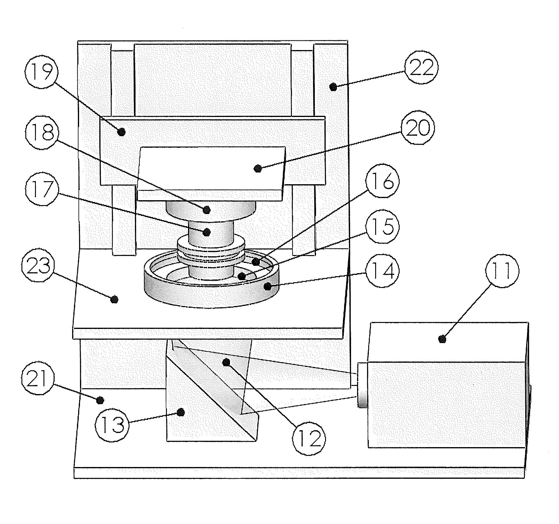
FIG. 1 is a perspective view of one embodiment of an apparatus of the present invention.
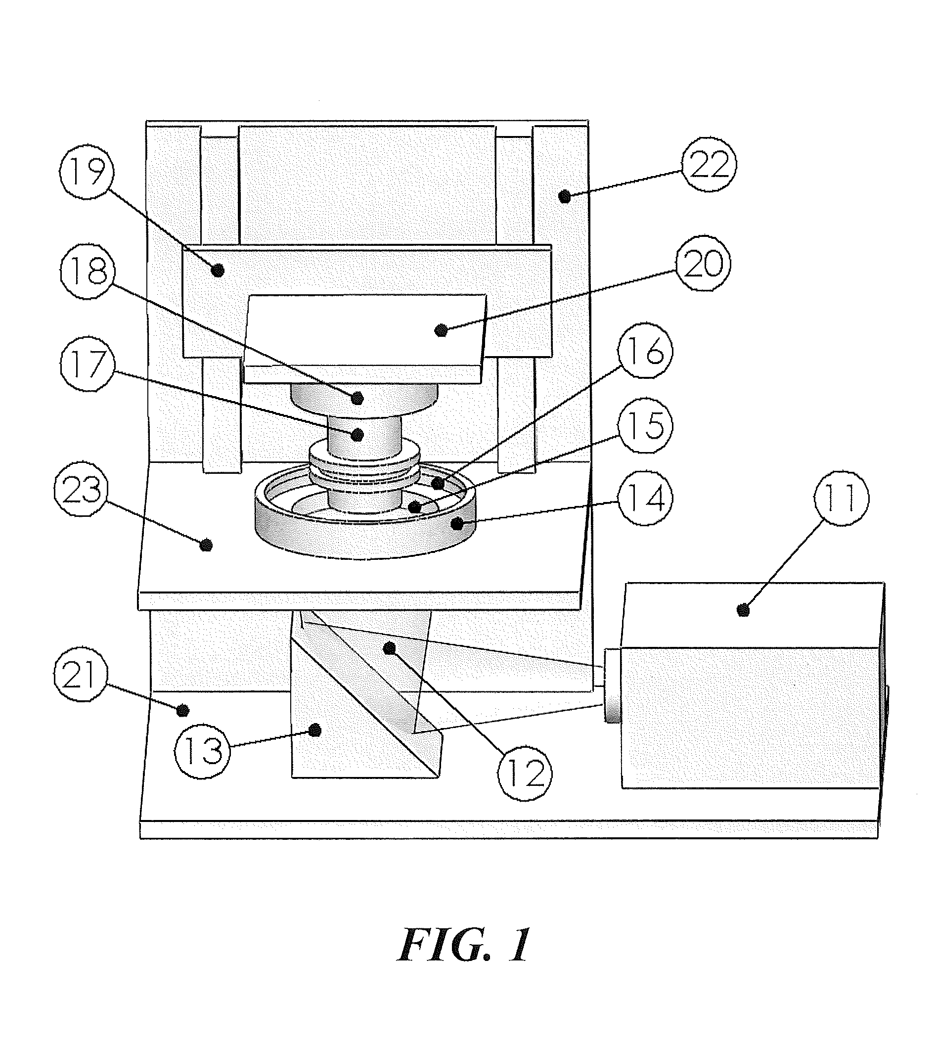
FIGS. 2A-2B provide side sectional views of alternate embodiments of rigid build plates for use in the present invention. FIG. 2A depicts a porous or microporous glass laminated or fixed to a rigid semipermeable member. FIG. 2B depicts a semipermeable member as an upper portion fixed to a transparent lower member having purging channels formed therein for feeding gas carrying the polymerization inhibitor to the semipermeable member.
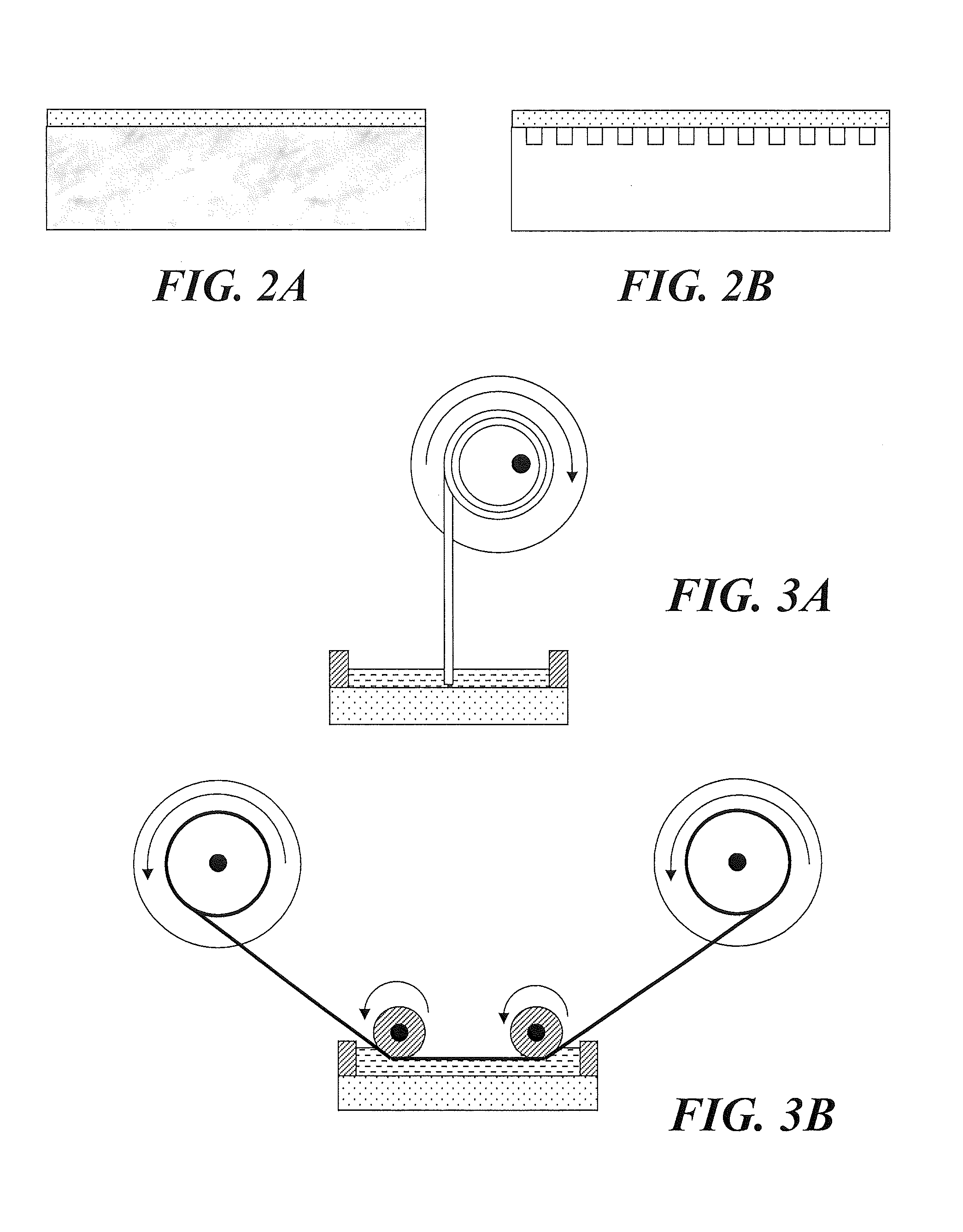
FIGS. 3A-3B illustrate various alternate carriers for use in the present invention. FIG. 3A depicts a carrier/actuator drive arrangement utilizing a take-up reel. FIG. 3B depicts a pair of take-up reels with associated guides.
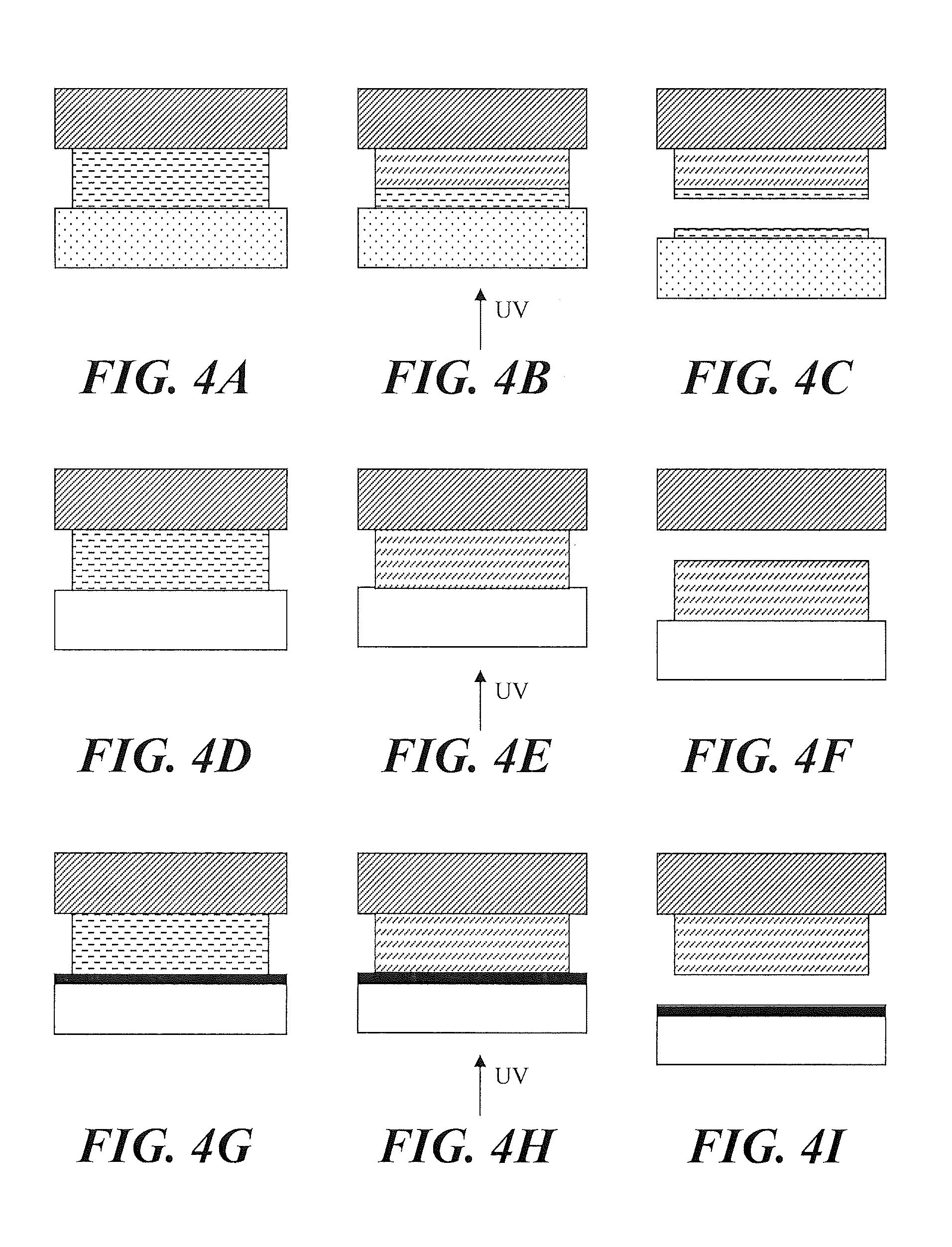
FIGS. 4A-4I illustrate a polymerization inhibitor in a rigid build plate aiding to establish a non-polymerized film on the build surface thereof. A drop of ultraviolet (UV) curable adhesive was placed on a metal plate and covered with 10 mm thick plate of TEFLON.RTM. AF fluoropolymer (FIG. 4A), followed by application of UV radiation to the adhesive from the side of TEFLON.RTM. AF (FIG. 4B). After UV exposure the two plates were separated (FIG. 4C). The resulting non-polymerized film on the build surface was compared to control experiments using clean glass (FIGS. 4D-4F) and glass treated with a release layer (FIGS. 4G-4I)
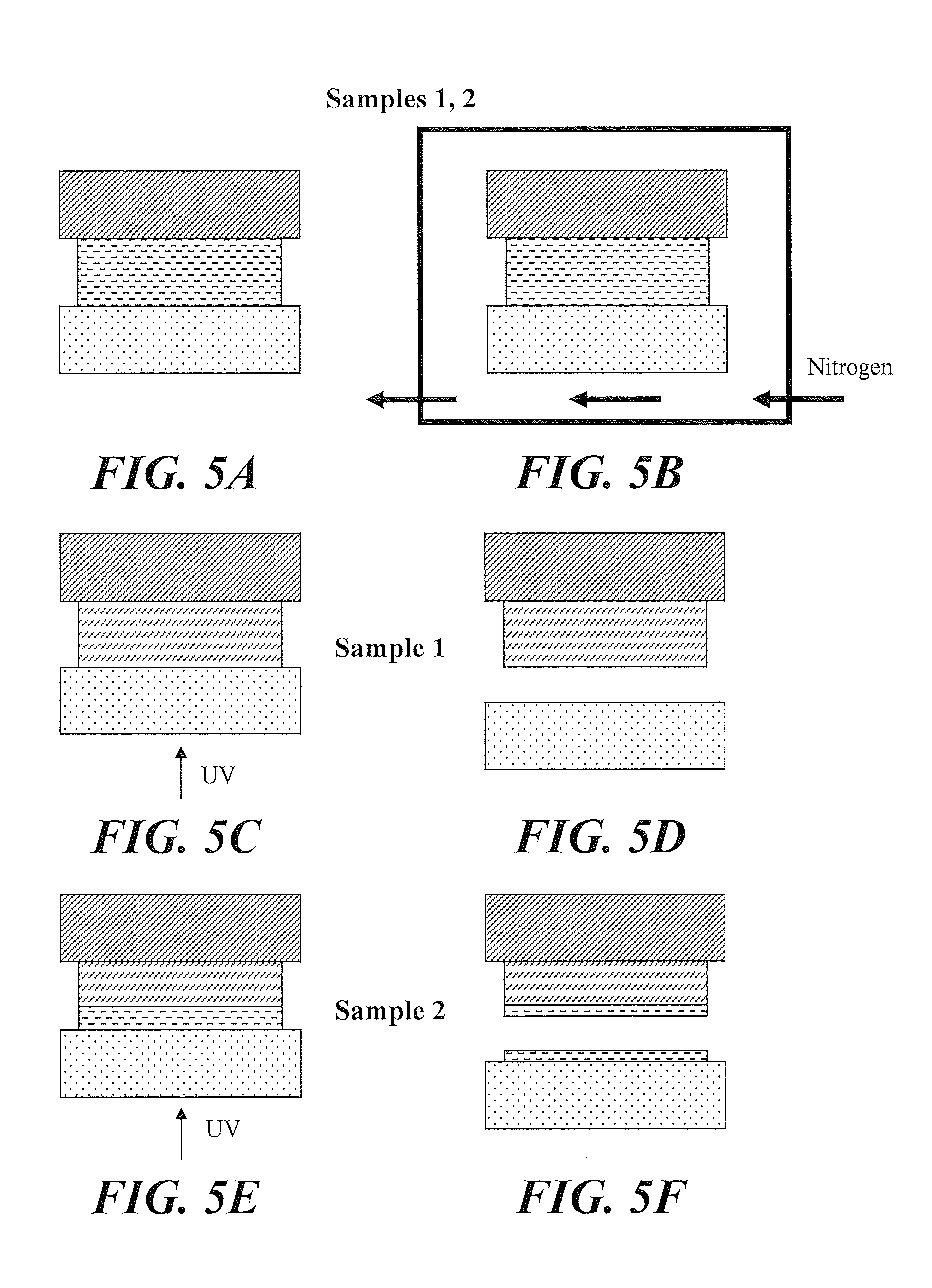
FIGS. 5A-5F illustrate the migration of an inhibitor (in this case oxygen) through a build plate from a feed surface on the back of the plate to a build surface on the front of a plate to aid in establishing a non-polymerized film on the build surface. Samples 1 and 2 were prepared in a similar manner wherein a drop of UV curable adhesive was placed on a metal plate and covered with 10 mm thick plate of TEFLON.RTM. AF fluoropolymer (FIG. 5A) then exposed to a nitrogen environment to eliminate the presence of oxygen (FIG. 5B). Both samples were brought into a standard atmosphere environment and Sample 1 was immediately exposed to UV radiation while Sample 2 was exposed to UV radiation 10 minutes after being in the atmosphere environment. Both samples received the same amount of UV radiation (FIG. 5C and FIG. 5E). The characteristics of the adhesive in both samples are shown in FIG. 5D and FIG. 5F, respectively.
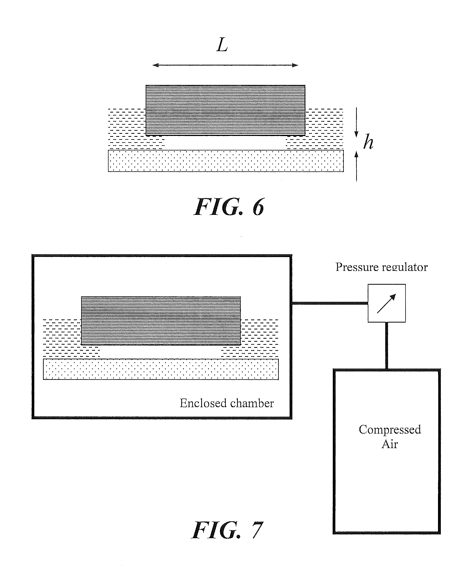
FIG. 6 schematically illustrates a growing three-dimensional object being advanced away from a build surface, and the gap that must be filled therebetween before subsequent polymerization can be carried out.
FIG. 7 schematically illustrates an embodiment of the invention which provides for the application of pressure to speed the filling of the gap shown in FIG. 8.
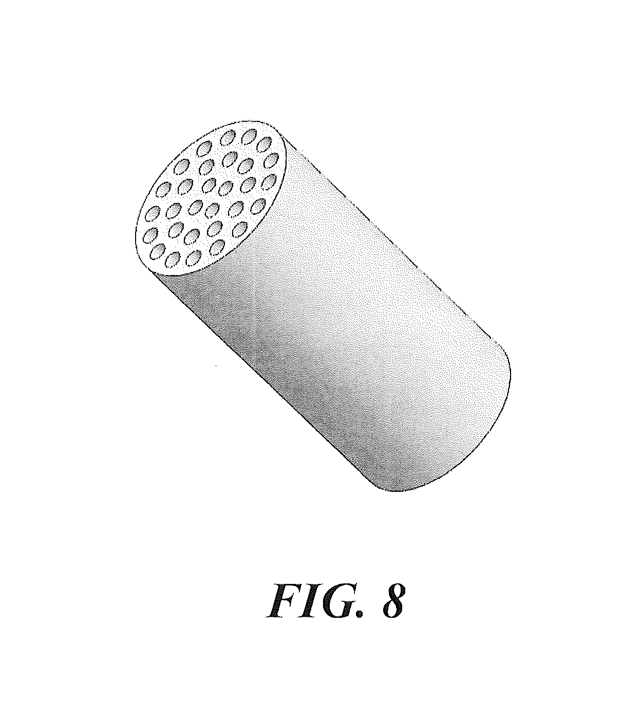
FIG. 8 illustrates a rod or fiber that can be produced by the methods and apparatus of the present invention.
DETAILED DESCRIPTION OF ILLUSTRATIVE EMBODIMENTS
The present invention is now described more fully hereinafter with reference to the accompanying drawings, in which embodiments of the invention are shown. This invention may, however, be embodied in many different forms and should not be construed as limited to the embodiments set forth herein; rather these embodiments are provided so that this disclosure will be thorough and complete and will fully convey the scope of the invention to those skilled in the art.
Like numbers refer to like elements throughout. In the figures, the thickness of certain lines, layers, components, elements or features may be exaggerated for clarity. Where used, broken lines illustrate optional features or operations unless specified otherwise.
The terminology used herein is for the purpose of describing particular embodiments only and is not intended to be limiting of the invention. As used herein, the singular forms "a," "an" and "the" are intended to include plural forms as well, unless the context clearly indicates otherwise. It will be further understood that the terms "comprises" or "comprising," when used in this specification, specify the presence of stated features, integers, steps, operations, elements components and/or groups or combinations thereof, but do not preclude the presence or addition of one or more other features, integers, steps, operations, elements, components and/or groups or combinations thereof.
As used herein, the term "and/or" includes any and all possible combinations or one or more of the associated listed items, as well as the lack of combinations when interpreted in the alternative ("or").
Unless otherwise defined, all terms (including technical and scientific terms) used herein have the same meaning as commonly understood by one of ordinary skill in the art to which this invention belongs. It will be further understood that terms, such as those defined in commonly used dictionaries, should be interpreted as having a meaning that is consistent with their meaning in the context of the specification and claims and should not be interpreted in an idealized or overly formal sense unless expressly so defined herein. Well-known functions or constructions may not be described in detail for brevity and/or clarity.
It will be understood that when an element is referred to as being "on," "attached" to, "connected" to, "coupled" with, "contacting," etc., another element, it can be directly on, attached to, connected to, coupled with and/or contacting the other element or intervening elements can also be present. In contrast, when an element is referred to as being, for example, "directly on," "directly attached" to, "directly connected" to, "directly coupled" with or "directly contacting" another element, there are no intervening elements present. It will also be appreciated by those of skill in the art that references to a structure or feature that is disposed "adjacent" another feature can have portions that overlap or underlie the adjacent feature.
Spatially relative terms, such as "under," "below," "lower," "over," "upper" and the like, may be used herein for ease of description to describe an element's or feature's relationship to another element(s) or feature(s) as illustrated in the figures. It will be understood that the spatially relative terms are intended to encompass different orientations of the device in use or operation in addition to the orientation depicted in the figures. For example, if the device in the figures is inverted, elements described as "under" or "beneath" other elements or features would then be oriented "over" the other elements or features. Thus the exemplary term "under" can encompass both an orientation of over and under. The device may otherwise be oriented (rotated 90 degrees or at other orientations) and the spatially relative descriptors used herein interpreted accordingly. Similarly, the terms "upwardly," "downwardly," "vertical," "horizontal" and the like are used herein for the purpose of explanation only, unless specifically indicated otherwise.
It will be understood that, although the terms first, second, etc., may be used herein to describe various elements, components, regions, layers and/or sections, these elements, components, regions, layers and/or sections should not be limited by these terms. Rather, these terms are only used to distinguish one element, component, region, layer and/or section, from another element, component, region, layer and/or section. Thus, a first element, component, region, layer or section discussed herein could be termed a second element, component, region, layer or section without departing from the teachings of the present invention. The sequence of operations (or steps) is not limited to the order presented in the claims or figures unless specifically indicated otherwise. 1. Polymerizable Liquids.
Any suitable polymerizable liquid can be used to enable the present invention. The liquid (sometimes also referred to as "liquid resin" herein) can include a monomer, particularly photopolymerizable and/or free radical polymerizable monomers, a suitable initiator such as a free radical initiator, and combinations thereof. Examples include, but are not limited to, acrylics, methacrylics, acrylamides, styrenics, olefins, halogenated olefins, cyclic alkenes, maleic anhydride, alkenes, alkynes, carbon monoxide, functionalized oligomers, multifunctional cute site monomers, functionalized PEGs, etc., including combinations thereof. Examples of liquid resins, monomers and initiators include but are not limited to those set forth in U.S. Pat. Nos. 8,232,043; 8,119,214; 7,935,476; 7,767,728; and 7,649,029.
The liquid resin or polymerizable material can have solid particles suspended or dispersed therein. Any suitable solid particle can be used, depending upon the end product being fabricated. The particles can be metallic, organic/polymeric, inorganic, or composites or mixtures thereof. The particles can be of any suitable shape, including spherical, elliptical, cylindrical, etc. The particles can comprise an active agent or detectable compound as described below, though these may also be provided dissolved solubilized in the liquid resin as also discussed below. For example, magnetic or paramagnetic particles or nanoparticles can be employed.
The liquid resin can have additional ingredients solubilized therein, including pigments, dyes, active compounds or pharmaceutical compounds, detectable compounds (e.g., fluorescent, phosphorescent, radioactive), etc., again depending upon the particular purpose of the product being fabricated. Examples of such additional ingredients include, but are not limited to, proteins, peptides, nucleic acids (DNA, RNA) such as siRNA, sugars, small organic compounds (drugs and drug-like compounds), etc., including combinations thereof.
Inhibitors or polymerization inhibitors for use in the present invention may be in the form of a liquid or a gas. In some embodiments, gas inhibitors are preferred. The specific inhibitor will depend upon the monomer being polymerized and the polymerization reaction. For free radical polymerization monomers, the inhibitor can conveniently be oxygen, which can be provided in the form of a gas such as air, a gas enriched in oxygen (optionally but in some embodiments preferably containing additional inert gases to reduce combustibility thereof), or in some embodiments pure oxygen gas. In alternate embodiments, such as where the monomer is polymerized by photoacid generator initiator, the inhibitor can be a base such as trace amines or carbon dioxide. 2. Apparatus.
A non-limiting embodiment of an apparatus of the invention is shown in FIG. 1. It comprises a radiation source 11 such as a digital light processor (DLP) providing electromagnetic radiation 12 which though reflective mirror 13 illuminates a build chamber defined by wall 14 and a rigid build plate 15 forming the bottom of the build chamber, which build chamber is filled with liquid resin 16. The bottom of the chamber 15 is constructed of rigid build plate comprising a rigid semipermeable member as discussed further below. The top of the object under construction 17 is attached to a carrier 18. The carrier is driven in the vertical direction by linear stage 19, although alternate structures can be used as discussed below.
A liquid resin reservoir, tubing, pumps liquid level sensors and/or valves can be included to replenish the pool of liquid resin in the build chamber (not shown for clarity) though in some embodiments a simple gravity feed may be employed. Drives/actuators for the carrier or linear stage, along with associated wiring, can be included in accordance with known techniques (again not shown for clarity). The drives/actuators, radiation source, and in some embodiments pumps and liquid level sensors can all be operatively associated with a suitable controller, again in accordance with known techniques.
Build plates 15 used to carry out the present invention generally comprise or consist of a a rigid semipermeable (or gas permeable) member, alone or in combination with one or more additional supporting substrates. The rigid semipermeable member can be made of any suitable material that is optically transparent at the relevant wavelengths (or otherwise transparent to the radiation source), including but not limited porous or microporous glass, and the rigid gas permeable polymers used for the manufacture of rigid gas permeable contact lenses. See, e.g., Norman G. Gaylord, U.S. Pat. No. RE31,406; see also U.S. Pat. Nos. 7,862,176; 7,344,731; 7,097,302; 5,349,394; 5,310,571; 5,162,469; 5,141,665; 5,070,170; 4,923,906; and 4,845,089. In some embodiments such materials are characterized as glassy and/or amorphous polymers. Preferably the rigid semipermeable member is formed of a material that does not swell when contacted to the liquid resin or material to be polymerized. Suitable materials for the rigid semipermeable member include rigid amorphous fluoropolymers, such as those described in U.S. Pat. Nos. 5,308,685 and 5,051,115. Particular materials include TEFLON AF.RTM. fluoropolymers, commercially available from DuPont. Additional materials include perfluoropolyether polymers such as described in U.S. Pat. Nos. 8,268,446; 8,263,129; 8,158,728; and 7,435,495.
The semipermeable member typically comprises a top surface portion, a bottom surface portion, and an edge surface portion. The build surface is on the top surface portion; and the feed surface may be on one, two, or all three of the top surface portion, the bottom surface portion, and/or the edge surface portion. In the embodiment illustrated in FIG. 1 the feed surface is on the bottom surface portion, but alternate configurations where the feed surface is provided on an edge, and/or on the top surface portion (close to but separate or spaced away from the build surface) can be implemented with routine skill.
The semipermeable member has, in some embodiments, a thickness of from 0.1 or 1 millimeters to 10 or 100 millimeters (depending upon the size of the item being fabricated, whether or not it is laminated to or in contact with an additional supporting plate such as glass, etc.
The permeability of the rigid semipermeable member will depend upon conditions such as the pressure of the atmosphere and/or inhibitor, the choice of inhibitor, the rate or speed of fabrication, etc. In general, when the inhibitor is oxygen, the permeability of the semipermeable member to oxygen may be from 10 or 20 Barrers, up to 1000 or 2000 Barrers, or more. For example, a semipermeable member with a permeability of 10 Barrers used with a pure oxygen, or highly enriched oxygen, atmosphere under a pressure of 150 PSI may perform substantially the same as a semipermeable member with a permeability of 500 Barrers when the oxygen is supplied from the ambient atmosphere under atmospheric conditions.
As shown in FIG. 1, the various components are mounted on a support or frame assembly 20. While the particular design of the support or frame assembly is not critical and can assume numerous configurations, in the illustrated embodiment it is comprised of a base 21 to which the radiation source 11 is securely or rigidly attached, a vertical member 22 to which the linear stage is operatively associated, and a horizontal table 23 to which wall 14 is removably or securely attached (or on which the wall is placed), and with the build plate rigidly fixed, either permanently or removably, to form the build chamber as described above.
As noted above, the build plate can consist of a single unitary and integral piece of a rigid semipermeable member, or can comprise additional materials. For example, as shown in FIG. 2A, a porous or microporous glass can be laminated or fixed to a rigid semipermeable material. Or, as shown in FIG. 2B, a semipermeable member as an upper portion can be fixed to a transparent lower member having purging channels formed therein for feeding gas carrying the polymerization inhibitor to the semipermeable member (through which it passes to the build surface to facilitate the formation of a release layer of unpolymerized liquid material, as noted above and below). Such purge channels may extend fully or partially through the base plate: For example, the purge channels may extend partially into the base plate, but then end in the region directly underlying the build surface to avoid introduction of distortion. Specific geometries will depend upon whether the feed surface for the inhibitor into the semipermeable member is located on the same side or opposite side as the build surface, on an edge portion thereof, or a combination of several thereof.
Any suitable radiation source (or combination of sources) can be used, depending upon the particular resin employed, including electron beam and ionizing radiation sources. In a preferred embodiment the radiation source is an actinic radiation source, such as one or more light sources, and in particular one or more ultraviolet light sources. Any suitable light source can be used, such as a laser, light-emitting diode, etc., including arrays thereof. The light source preferably includes a pattern-forming element operatively associated with a controller, as noted above. In some embodiments, the light source or pattern forming element comprises a digital micromirror device (DMD) with digital light processing (DLP), a spatial modulator (SLM), or a microelectromechanical system (MEMS) mirror array, a mask (aka a reticle), a silhouette, or a combination thereof. See, U.S. Pat. No. 7,902,526.
Alternate carriers and actuator/drive arrangements are shown in FIGS. 3A-3B. Numerous variations can be employed, including a take-up reel, an XYZ drive assembly (e.g., as commonly used on an automated microscope stage), etc. In the embodiment illustrated in FIG. 1 the drive assembly will generally comprise a worm gear and motor, a rack and pinion and motor, a hydraulic, pneumatic, or piezoelectric drive, or the like, adapted to move or advance the carrier away from the build surface in the vertical or "Z" direction only. In the alternative embodiment shown FIG. 3A a spool or take-up real can be utilized, with associated drives or actuators and guides (not shown), particularly when the product being fabricated is an elongated rod or fiber (discussed further below). In the embodiment shown in FIG. 3B, a pair of take-up reels with associated guides, and associated drives or actuators (not shown), can be mounted on linear stage 19 to provide movement in either the X and/or Y direction, in alternative to, or in addition to or in combination with, movement in the Z direction provided by linear stage 19. In still other embodiments, an XYZ drive assembly like that used in an automated microscope can be used in place of linear stage 19 to move or advance the carrier away from the build surface in the X, Y, and/or Z direction, e.g., at an angle, or at changing angles, or combinations of directions at various stages. Thus advancement away from the build plate can be carried out solely in the Z (or vertical) direction, solely in the X and/or Y (horizontal) directions, in at least the Z direction, or in at least the X and/or Y directions, by combining movement in the Z direction with movement in the X and/or Y directions. 3. Methods.
As noted above, the present invention provides a method of forming a three-dimensional object, comprising the steps of: (a) providing a carrier and a build plate, said build plate comprising a f semipermeable member, said semipermeable member comprising a build surface and a feed surface separate from said build surface, with said build surface and said carrier defining a build region therebetween, and with said feed surface in fluid contact with a polymerization inhibitor; then (concurrently and/or sequentially) (b) filing said build region with a polymerizable liquid, said polymerizable liquid contacting said build segment, (c) irradiating said build region through said build plate to produce a solid polymerized region in said build region, with a liquid film release layer comprised of said polymerizable liquid formed between said solid polymerized region and said build surface, the polymerization of which liquid film is inhibited by said polymerization inhibitor; and (d) advancing said carrier with said polymerized region adhered thereto away from said build surface on said stationary build plate to create a subsequent build region between said polymerized region and said top zone. In general the method includes (e) continuing and/or repeating steps (b) through (d) to produce a subsequent polymerized region adhered to a previous polymerized region until the continued or repeated deposition of polymerized regions adhered to one another forms said three-dimensional object.
Since no mechanical release of a release layer is required, or no mechanical movement of a build surface to replenish oxygen is required, the method can be carried out in a continuous fashion, though it will be appreciated that the individual steps noted above may be carried out sequentially, concurrently, or a combination thereof. Indeed, the rate of steps can be varied over time depending upon factors such as the density and/or complexity of the region under fabrication.
In some embodiments, the advancing step is carried out sequentially in uniform increments (e.g., of from 0.1 or 1 microns, up to 10 or 100 microns, or more) for each step or increment. In some embodiments, the advancing step is carried out sequentially in variable increments (e.g., each increment ranging from 0.1 or 1 microns, up to 10 or 100 microns, or more) for each step or increment. The size of the increment, along with the rate of advancing, will depend in part upon the presence or absence of pressure for the introducing step, as discussed further below.
As described further below, in some embodiments the filling step is carried out by forcing said polymerizable liquid into said build region under pressure. In such a case, the advancing step or steps may be carried out at a rate or cumulative or average rate of at least 0.1, 1, 10, 50, 100, 500 or 1000 microns per second, or more. In general, the pressure may be whatever is sufficient to increase the rate of said advancing step(s) at least 2, 4, 6, 8 or 10 times as compared to the maximum rate of repetition of said advancing steps in the absence of said pressure. Where the pressure is provided by enclosing an apparatus such as described above in a pressure vessel and carrying the process out in a pressurized atmosphere (e.g., of air, air enriched with oxygen, a blend of gasses, pure oxygen, etc.) a pressure of 10, 20, 30 or 40 pounds per square inch (PSI) up to, 200, 300, 400 or 500 PSI or more, may be used. For fabrication of large irregular objects higher pressures may be less preferred as compared to slower fabrication times due to the cost of a large high pressure vessel. In such an embodiment, both the feed surface and the polymerizable liquid can be are in fluid contact with the same compressed gas (e.g., one comprising from 20 to 95 percent by volume of oxygen, the oxygen serving as the polymerization inhibitor.
On the other hand, when smaller items are fabricated, or a rod or fiber is fabricated that can be removed or exited from the pressure vessel as it is produced through a port or orifice therein, then the size of the pressure vessel can be kept smaller relative to the size of the product being fabricated and higher pressures can (if desired) be more readily utilized.
As noted above, the irradiating step is in some embodiments carried out with patterned irradiation. The patterned irradiation may be a fixed pattern or may be a variable pattern created by a pattern generator (e.g., a DLP) as discussed above, depending upon the particular item being fabricated.
In some embodiments the build surface is flat; in other the build surface is irregular such as convexly or concavely curved, or has walls or trenches formed therein. In either case the build surface may be smooth or textured. Curved and/or irregular build plates or build surfaces can be used in fiber or rod formation, to provide different materials to a single object being fabricated (that is, different polymerizable liquids to the same build surface through channels or trenches formed in the build surface, each associated with a separate liquid supply, etc. 4. Fabrication Products.
Numerous different products can be made by the methods and apparatus of the present invention, including both large-scale models or prototypes, small custom products, miniature or microminiature products or devices, etc. Examples include, but are not limited to, medical devices and implantable medical devices such as stents, drug delivery depots, functional structures, fibers and rods such as waveguides, micromechanical devices, microfluidic devices, etc.
Thus in some embodiments the product can have a height of from 0.1 or 1 millimeters up to 10 or 100 millimeters, or more, and/or a maximum width of from 0.1 or 1 millimeters up to 10 or 100 millimeters, or more. In other embodiments, the product can have a height of from 10 or 100 nanometers up to 10 or 100 microns, or more, and/or a maximum width of from 10 or 100 nanometers up to 10 or 100 microns, or more. These are examples only: Maximum size and width depends on the architecture of the particular device and the resolution of the light source and can be adjusted depending upon the particular goal of the embodiment or article being fabricated.
In some embodiments, the ratio of height to width of the product is at least 2:1, 10:1, 50:1, or 100:1, or more, or a width to height ratio of 1:1, 10:1, 50:1, or 100:1, or more.
In some embodiments, the product has at least one, or a plurality of, pores or channels formed therein, as discussed further below.
The present invention is explained in greater detail in the following non-limiting Examples.
EXAMPLE 1
Inhibitor Transfer to Build Surface from a Separate Feed Surface
A drop of ultraviolet (UV) curable adhesive was placed on a metal plate and covered with 10 mm thick plate of TEFLON.RTM. AF fluoropolymer (a rigid, amorphous, glassy polymer) as shown in FIG. 4A. UV radiation was supplied to the adhesive from the side of TEFLON.RTM. AF as shown in FIG. 4B. After UV exposure the two plates were separated. It was found that no force was required to separate the two plates. Upon examination of the samples it was discovered that the adhesive was cured only next to the metal plate, and that a thin film of uncured adhesive was present on the Teflon AF fluoropolymer plate and also on the cured portion of the adhesive as shown in FIG. 4C.
Two controlled experiments were also performed where clean glass (FIGS. 4D-4F) and also glass treated with a release layer (FIGS. 4G-4I) was used. It was confirmed that considerable force was needed to separate clean glass from the metal and it was found that adhesive remained on the glass. Less force was needed to separate the treated glass, while adhesive remained on the metal plate.
The chemical phenomenon which describes the observed behavior is oxygen inhibition of the radical polymerization reaction. In particular, Teflon AF has a very high oxygen permeability coefficient. Constant supply of oxygen through 10 mm think Teflon AF is sufficient to prevent a thin layer of acrylate adhesive from polymerization. The thickness of uncured adhesive layer in the above experiment was on the order of 10 microns and it can be increased or decreased by varying the amount of photo initiator present in the adhesive.
EXAMPLE 2
Inhibitor Transfer through Build Plate to Build Surface
Samples 1 and 2 were prepared in a similar manner wherein a drop of UV curable adhesive was placed on a metal plate and covered with 10 mm thick plate of TEFLON.RTM. AF fluoropolymer as shown in FIG. 5A. Both samples were exposed to a nitrogen environment to eliminate any presence of oxygen as shown in FIG. 5B. Next both samples were brought into a standard atmosphere environment and Sample 1 was immediately exposed to UV radiation while Sample 2 was exposed to UV radiation 10 minutes after being in the atmosphere environment. Both samples were exposed to the same amount of UV radiation as shown in FIG. 5C and FIG. 5E. Upon examination of the samples after UV exposure it was discovered that the adhesive was cured completely in Sample 1 as shown in FIG. 5D and only next to the metal plate in Sample 2 as shown in FIG. 5F. A thin film of uncured adhesive was present on the Teflon AF fluoropolymer plate and also on the cured portion of the adhesive for Sample 2. This experiment shows that the inhibitor, oxygen, was transferred through Teflon AF plate to the adhesive during the 10 minute period of being exposed to the atmosphere environment.
EXAMPLE 3
Increasing Fabrication Rate
A highly oxygen permeable, rigid, and UV transparent material is to used as the bottom of a chamber filled with photocurable resin in a device of the invention. During construction, the top of an object is attached to a support plate which is moved up at a substantially constant speed while the bottom portion of the object is constantly being formed just above the bottom of the chamber. The gap between the bottom of the object and the bottom of the chamber is always filled with resin. As the object is being formed and advanced, the resin in the gap is constantly replenished with supply resin contained in the chamber.
The speed of the object's formation depends on the viscosity of the resin .eta., atmospheric pressure P, the height of the gap between the object and the bottom of the chamber h, and the linear dimension L of the object's bottom surface. Simple calculations are performed to estimate this speed using the theory of viscous flow between two parallel plates. The time .tau. which is required to fill the gap shown on FIG. 6 is given by the equation:
.tau..times..about..times..times..eta. ##EQU00001## Assuming: L.about.100 mm h.about.100 microns .eta..about.100 cPoise P.about.1 atm
In this illustrative embodiment, the time .tau. is estimated to be of an order of 1 second, resulting in fabrication speeds of 100 microns per second or 5 minutes per inch. These calculations assume that the thickness of the uncured resin is maintained at about 100 microns. Depending on the chemistry of the resin and permeability of the base plate, this parameter may vary. If, for example, the gap is 25 microns, then fabrication speeds at atmospheric pressure will decrease according to Equation 1 by a factor of 16. However, increasing the ambient pressure to greater than atmospheric pressure, e.g., by applying external pressure on the order of 150 PSI as shown in FIG. 7, may in some embodiments increase fabrication speed by a factor of 10.
When oxygen is the polymerization inhibitor, the gap of uncured resin can be controlled by altering the physical environment in the enclosed chamber contacting feed surface. For example, an atmosphere of pure oxygen, or enriched in oxygen (e.g., 95% oxygen 5% carbon dioxide) can be provided in place of compressed air, order to increase the gap resulting in increase of fabrication time.
EXAMPLE 4
Fabrication of Rods and Fibers
The methods of the present invention can be used to make an elongate rod or fiber as shown in FIG. 8, the rod or fiber having (for example) a width or diameter of 0.01 or 0.1 to 10 or 100 millimeters. While a circular cross-section is shown, any suitable cross-section can be utilized, including elliptical, polygonal (triangular, square, pentagonal, hexagonal, etc.) irregular, and combinations thereof. The rod or fiber can have a plurality of elongated pores or channels formed therein (e.g., 1, 10, 100 1,000, 10,000 or 100,000 or more) of any suitable diameter (e.g., 0.1 or 1 microns, up to 10 or 100 microns or more) and any suitable cross-section as described above. Unpolymerized liquid in the pores or channels can be removed (if desired) by any suitable technique, such as blowing, pressure, vacuum, heating, drying and combinations thereof. The length of the rod or fiber can be increased by utilizing a take-up reel as described above, and the speed of fabrication of the rod or fiber can be increased by carrying out the polymerization under pressure as described above. A plurality of such rods or fibers can be constructed concurrently from a single build plate by providing a plurality of independent carriers or take-up reels. Such rods or fibers can be used for any purpose, such as utilizing each pore or channel therein as an independent channel in a microfluidic system.
The foregoing is illustrative of the present invention, and is not to be construed as limiting thereof. The invention is defined by the following claims, with equivalents of the claims to be included therein.
* * * * *
References
uspto.report is an independent third-party trademark research tool that is not affiliated, endorsed, or sponsored by the United States Patent and Trademark Office (USPTO) or any other governmental organization. The information provided by uspto.report is based on publicly available data at the time of writing and is intended for informational purposes only.
While we strive to provide accurate and up-to-date information, we do not guarantee the accuracy, completeness, reliability, or suitability of the information displayed on this site. The use of this site is at your own risk. Any reliance you place on such information is therefore strictly at your own risk.
All official trademark data, including owner information, should be verified by visiting the official USPTO website at www.uspto.gov. This site is not intended to replace professional legal advice and should not be used as a substitute for consulting with a legal professional who is knowledgeable about trademark law.