Smart mechanical component
Wu , et al.
U.S. patent number 10,704,987 [Application Number 15/455,559] was granted by the patent office on 2020-07-07 for smart mechanical component. This patent grant is currently assigned to INDUSTRIAL TECHNOLOGY RESEARCH INSTITUTE. The grantee listed for this patent is INDUSTRIAL TECHNOLOGY RESEARCH INSTITUTE. Invention is credited to An-Li Chen, Chuan-Sheng Chuang, Wei-Chin Huang, Ching-Chih Lin, De-Yau Lin, Sung-Yueh Wu.


View All Diagrams
| United States Patent | 10,704,987 |
| Wu , et al. | July 7, 2020 |
Smart mechanical component
Abstract
A smart mechanical component has a mechanical part main body; a mechanical part secondary body located inside of the mechanical part main body; a three dimensional three-dimensional (3-D) reserved space located between the mechanical part main body and the mechanical part secondary body; at least one connecting unit connecting the mechanical part main body and the mechanical part secondary body; wherein the mechanical part main body, the mechanical part secondary body and the three dimensional three-dimensional (3-D) reserved space form a capacitor; the connecting unit forms an inductor; the inductor and the capacitor forms an inductor-capacitor circuit.
| Inventors: | Wu; Sung-Yueh (Chiayi County, TW), Lin; De-Yau (Tainan, TW), Chen; An-Li (Tainan, TW), Lin; Ching-Chih (Tainan, TW), Chuang; Chuan-Sheng (Tainan, TW), Huang; Wei-Chin (Tainan, TW) | ||||||||||
|---|---|---|---|---|---|---|---|---|---|---|---|
| Applicant: |
|
||||||||||
| Assignee: | INDUSTRIAL TECHNOLOGY RESEARCH
INSTITUTE (Hsin-Chu, TW) |
||||||||||
| Family ID: | 62107721 | ||||||||||
| Appl. No.: | 15/455,559 | ||||||||||
| Filed: | March 10, 2017 |
Prior Publication Data
| Document Identifier | Publication Date | |
|---|---|---|
| US 20180136153 A1 | May 17, 2018 | |
Foreign Application Priority Data
| Nov 15, 2016 [TW] | 105137318 A | |||
| Current U.S. Class: | 1/1 |
| Current CPC Class: | G01M 13/00 (20130101); F16B 31/06 (20130101); F16B 45/00 (20130101) |
| Current International Class: | F16B 31/06 (20060101); G01M 13/00 (20190101); F16B 45/00 (20060101) |
References Cited [Referenced By]
U.S. Patent Documents
| 3085182 | April 1963 | Napolin |
| 5945892 | August 1999 | Kato |
| 6025725 | February 2000 | Gershenfeld et al. |
| 6910385 | June 2005 | Shkel |
| 7181975 | February 2007 | Bradley et al. |
| 7290454 | November 2007 | Liu |
| 7726199 | June 2010 | Shkel et al. |
| 8104358 | January 2012 | Jia et al. |
| 8259076 | September 2012 | Trent, Jr. et al. |
| 8364419 | January 2013 | Potyrailo et al. |
| 8443676 | May 2013 | Burghardt et al. |
| 8493187 | July 2013 | Rowland et al. |
| 8601880 | December 2013 | Berkcan et al. |
| 8984952 | March 2015 | Barron et al. |
| 9038483 | May 2015 | Nagarajan et al. |
| 9291586 | March 2016 | Neikirk et al. |
| 9305456 | April 2016 | Rowland et al. |
| 9457517 | October 2016 | Cheng et al. |
| 9533350 | January 2017 | Zhuang et al. |
| 2003/0030510 | February 2003 | Sasaki |
| 2009/0009276 | January 2009 | Jidaisho |
| 2010/0259282 | October 2010 | Niwa |
| 2015/0109074 | April 2015 | Son |
| 2015/0147722 | May 2015 | Tsai et al. |
| 2015/0150614 | June 2015 | Tsai et al. |
| 2015/0174822 | June 2015 | Huang et al. |
| 2016/0103084 | April 2016 | Kleczewski |
| 2016/0114531 | April 2016 | Chuang et al. |
| 2016/0128843 | May 2016 | Tsau et al. |
| 2016/0184925 | June 2016 | Huang et al. |
| 102683773 | Sep 2012 | CN | |||
| 103743503 | Apr 2014 | CN | |||
| 204330987 | May 2015 | CN | |||
| 104665905 | Jun 2015 | CN | |||
| 104665906 | Jun 2015 | CN | |||
| 104665913 | Jun 2015 | CN | |||
| 205487870 | Aug 2016 | CN | |||
| I374265 | Oct 2012 | TW | |||
| I414762 | Nov 2013 | TW | |||
| I442903 | Jul 2014 | TW | |||
| 201519852 | Jun 2015 | TW | |||
| I536955 | Jun 2016 | TW | |||
| I545269 | Aug 2016 | TW | |||
| I547258 | Sep 2016 | TW | |||
| I548390 | Sep 2016 | TW | |||
Other References
|
Intellectual Property Office Ministry of Economic Affairs, R.O.C., "Office Action", dated Jul. 26, 2017, Taiwan. cited by applicant . Eric Macdonald et al., 3D Printing for the Rapid Prototyping of Structural Electronics, IEEE Access, 2014, 234-242, vol. 2. cited by applicant . Sung-Yueh Wu et al., 3D-printed microelectronics for integrated circuitry and passive wireless sensors, Microsystems & Nanoengineering, 2015. cited by applicant . Sung-Yueh Wu et al., A wirelessly readable and resettable shock recorder through the integration of LC circuits and MEMS devices, Smart Materials and Structures, 2014, 23. cited by applicant . Jennifer A. Lewis et al., Three-dimensional printed electronics, Nature, 2015, vol. 518. cited by applicant . K.G. Ong et al., Design and application of a wireless, passive, resonant-circuit environmental monitoring sensor, Sensors and Actuators A: Physical, 2001, 33-43, vol. 93. cited by applicant . China Patent Office, "Office Action", dated Jun. 3, 2019, China. cited by applicant. |
Primary Examiner: Zakaria; Akm
Attorney, Agent or Firm: Locke Lord LLP Xia, Esq.; Tim Tingkang
Claims
What is claimed is:
1. A smart mechanical component, comprising: a main body, wherein the main body is a screw or a hook; a secondary body, wherein the secondary body is an inner shaft furnished in the main body, and the main body is not in contact with the secondary body; a three-dimensional (3-D) reserved space, positioned between the main body and the secondary body; and an inductor bridged between the main body and the secondary body and located adjacent to a head part of the main body, wherein the inductor has a spiral shape, a center end of the inductor connects to an end of the inner shaft, and a spiral end of the inductor connects to the screw or the hook, for connecting the main body and the secondary body; wherein, the main body, the secondary body and the three-dimensional (3-D) reserved space form a capacitor, and the inductor and the capacitor to form an inductor-capacitor (LC) circuit; and wherein the secondary body extends from one end of the main body to another end of the main body, and the secondary body is coaxial to the main body.
2. The smart mechanical component of claim 1, wherein the main body, the secondary body and the inductor are integrally formed or are laminated together.
3. The smart mechanical component of claim 1, wherein a film is formed on the surfaces of the main body, the secondary body and the inductor.
4. The smart mechanical component of claim 1, wherein a magnetic material is disposed surrounding the inductor.
5. The smart mechanical component of claim 1, wherein the three-dimensional (3-D) reserved space is filled or partially filled with a dielectric material.
6. The smart mechanical component of claim 1, wherein the three-dimensional (3-D) reserved space is designed to be adjustable by a driving of an external force or by a use of a regulator.
7. The smart mechanical component of claim 1, wherein the LC circuit is provided for allowing its resonance frequency or quality factor of resonance to be readable by a reader.
8. The smart mechanical component of claim 1, wherein the inductor is connected to at least two ends of the main body.
9. The smart mechanical component of claim 1, wherein the main body, the secondary body and the inductor are electrical conductors.
10. The smart mechanical component of claim 1, wherein the inductor is substantially a coil.
11. A smart mechanical component, comprising: a secondary body, wherein the secondary body is a pad with a hole in the center; a main body, wherein the main body is a screw furnished by penetrating through the hole of the secondary body, and the main body is not in contact with the secondary body; and an inductor bridged between the main body and the secondary body and having a spiral shape, wherein a spiral end of the inductor connects to a periphery of the pad, and a center end of the inductor connects to a head part of the screw, for connecting the main body and the secondary body; wherein, a three-dimensional (3-D) reserved space is formed between the main body and the secondary body; the secondary body, the main body and the three-dimensional (3-D) reserved space form a capacitor, and the inductor and the capacitor form an inductor-capacitor (LC) circuit.
12. The smart mechanical component of claim 11, wherein the main body is a component selected from the group consisting of: a screw, a bolt, a screw rod, a slide rail, a peg or a hook.
13. The smart mechanical component of claim 11, wherein the main body, the secondary body and the inductor are integrally formed or are laminated together.
14. The smart mechanical component of claim 11, wherein there is a film is formed on the surfaces of the main body, the secondary body and the inductor.
15. The smart mechanical component of claim 11, wherein the three-dimensional (3-D) reserved space is designed to be adjustable by a driving of an external force or by a use of a regulator.
16. The smart mechanical component of claim 11, wherein the LC circuit is provided for allowing its resonance frequency or quality factor of resonance to be readable by a reader.
17. The smart mechanical component of claim 11, wherein the main body, the secondary body and the inductor are electrical conductors.
18. The smart mechanical component of claim 11, wherein the inductor is substantially a coil.
19. The smart mechanical component of claim 11, wherein magnetic material is disposed surrounding the inductor.
20. The smart mechanical component of claim 11, wherein the three-dimensional (3-D) reserved space is filled or partially filled with a dielectric material.
Description
CROSS REFERENCE TO RELATED APPLICATION
This application also claims priority to Taiwan Patent Application No. 105137318 filed in the Taiwan Patent Office on Nov. 15, 2016, the entire content of which is incorporated herein by reference.
TECHNICAL FIELD
The present disclosure relates to a smart mechanical component, and more particularly, to a mechanical component capable of determining if the mechanical component needs to be replaced by the detection of a resonance effect from an inductor-capacitor (LC) circuit built inside the mechanical component.
BACKGROUND
Screws, bolts, screw rods or hooks are the most basic and most important mechanical parts, which are used in aerospace, medical, heavy industry or people's livelihood industry. However, in the long-term use, they are proned to damage by fatigue, stretching, bending, extrusion or fracture.
Generally, there is no sensor that is designed to build inside those essential parts for damage detection. The most common way used in the industry for achieving such damage detection is by installing an addition sensor, which can be extremely inconvenient to use. In addition, those additional sensors may require to be replaced in a regular base or may not be replaced until themselves are damaged. However, there are some working environments where even a simple condition caused by damaged part is not allowed, such as aircrafts, nuclear power plants, chemical factories, heavy-duty machineries, harbors, or power plants.
SUMMARY
In an embodiment, the present disclosure provides a smart mechanical component, comprising:
a main body;
a secondary body, arranged inside of the main body; a three-dimensional (3-D) reserved space, formed between the main body and the secondary body; and at least one connecting unit, for connecting the main body and the secondary body; wherein, the main body, the secondary body and the three-dimensional (3-D) reserved space form a capacitor, and the at least one connecting unit forms an inductor, while enabling the inductor and the capacitor to form an LC circuit.
In another embodiment, the present disclosure provides a smart mechanical component, comprising: a secondary body; a main body, arranged boring through the second body; and a connecting unit, for connecting the main body and the secondary body; wherein, there is a three-dimensional (3-D) reserved space formed between the main body and the secondary body, while allowing the three-dimensional (3-D) reserved space to be disposed at a position between the connecting unit and the secondary body; and the secondary body, the main body and the three-dimensional (3-D) reserved space form a capacitor, and the connecting unit forms an inductor, while enabling the inductor and the capacitor to form an LC circuit.
Further scope of applicability of the present application will become more apparent from the detailed description given hereinafter. However, it should be understood that the detailed description and specific examples, while indicating exemplary embodiments of the disclosure, are given by way of illustration only, since various changes and modifications within the spirit and scope of the disclosure will become apparent to those skilled in the art from this detailed description.
BRIEF DESCRIPTION OF THE DRAWINGS
The present disclosure will become more fully understood from the detailed description given herein below and the accompanying drawings which are given by way of illustration only, and thus are not limitative of the present disclosure and wherein:
FIG. 1A is a sectional view of a smart mechanical component according to a first embodiment of the present disclosure.
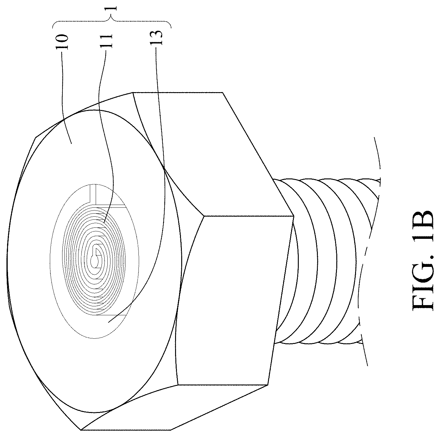
FIG. 1B is a partial view of a connecting unit used in the present disclosure.
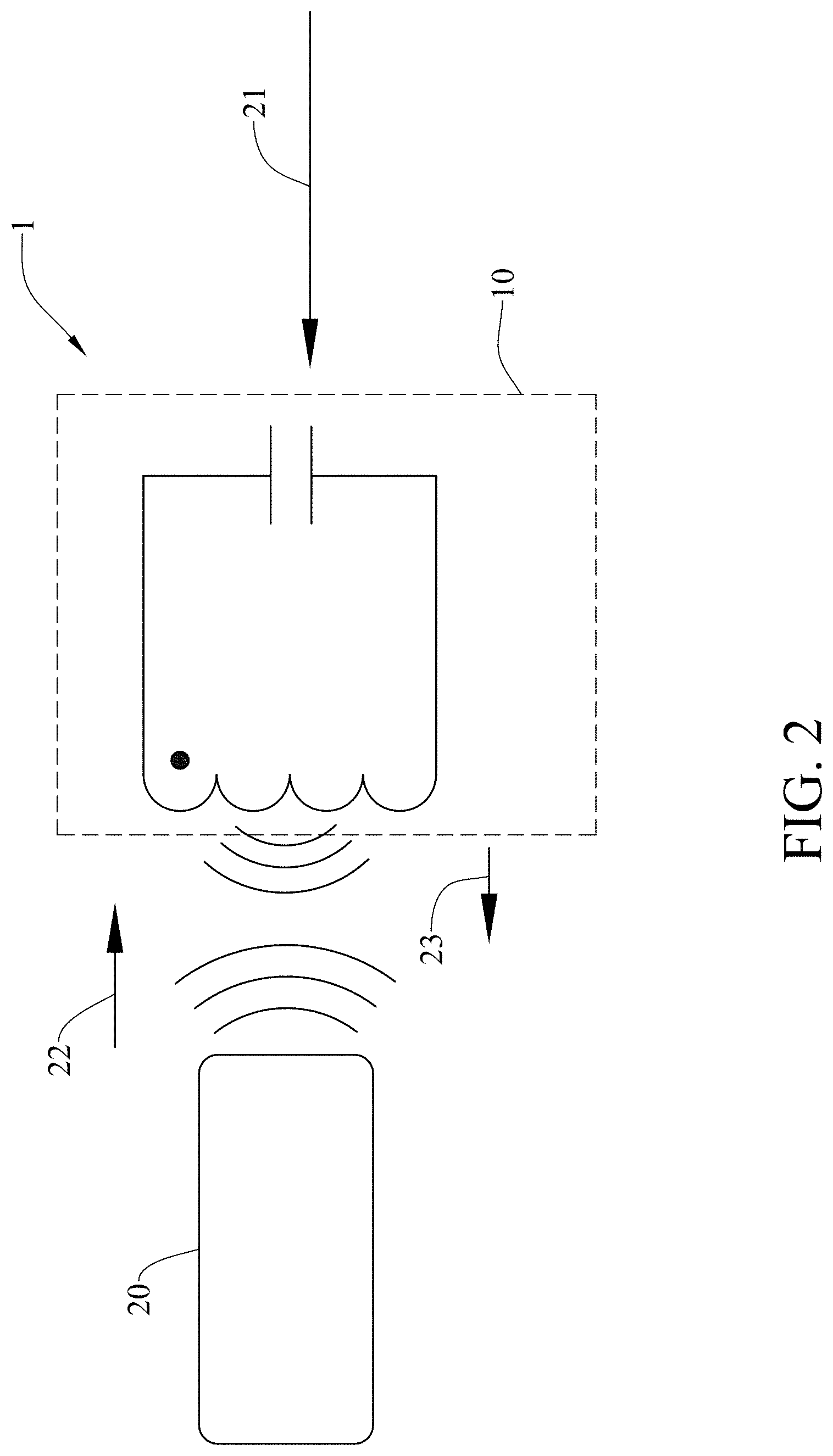
FIG. 2 is a schematic diagram showing the sign communication between a signal reader and a smart mechanical component of the present disclosure.
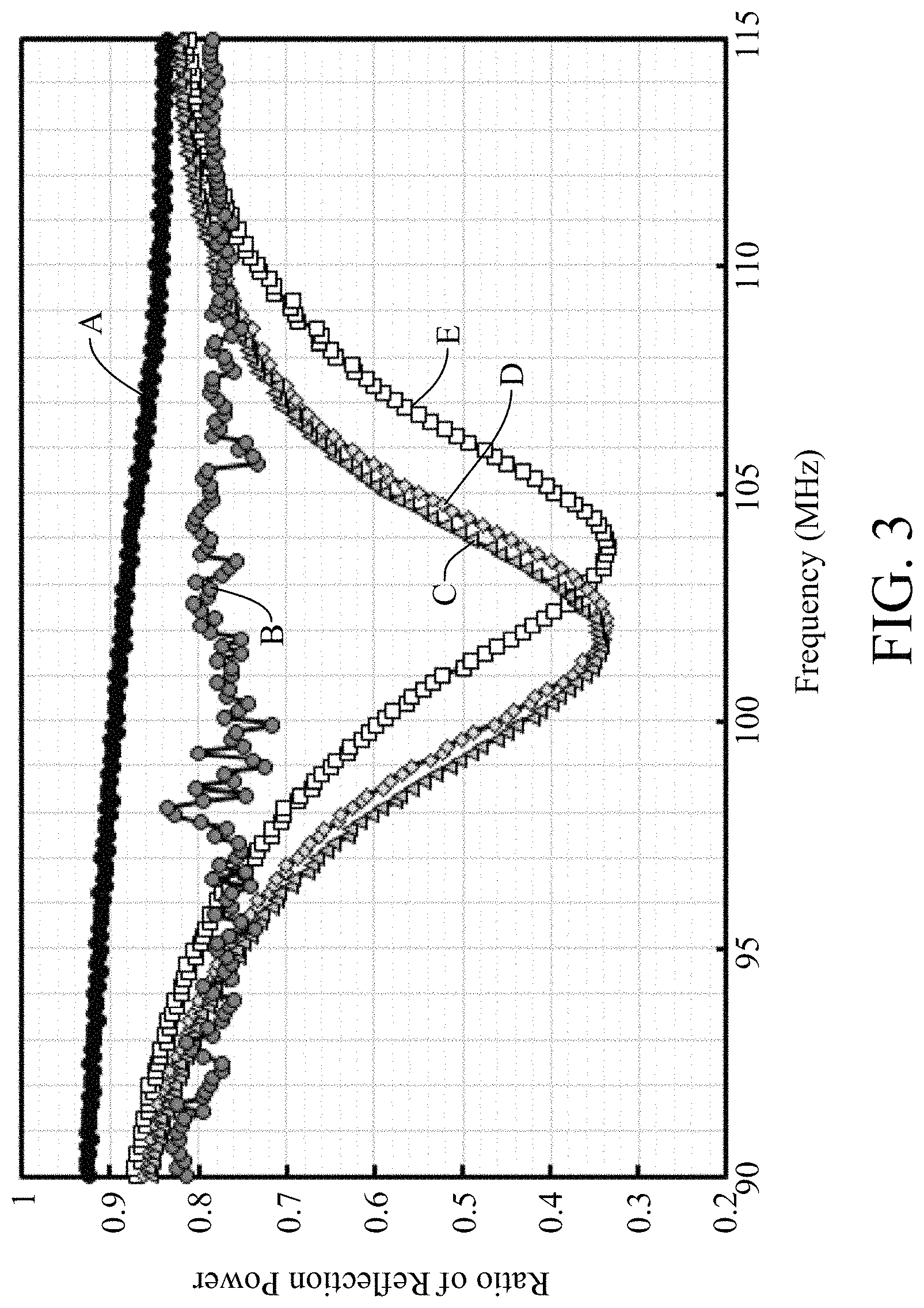
FIG. 3 is a schematic diagram showing the relationship between frequency and magnitude resonance frequency in a smart mechanical component of the present disclosure.
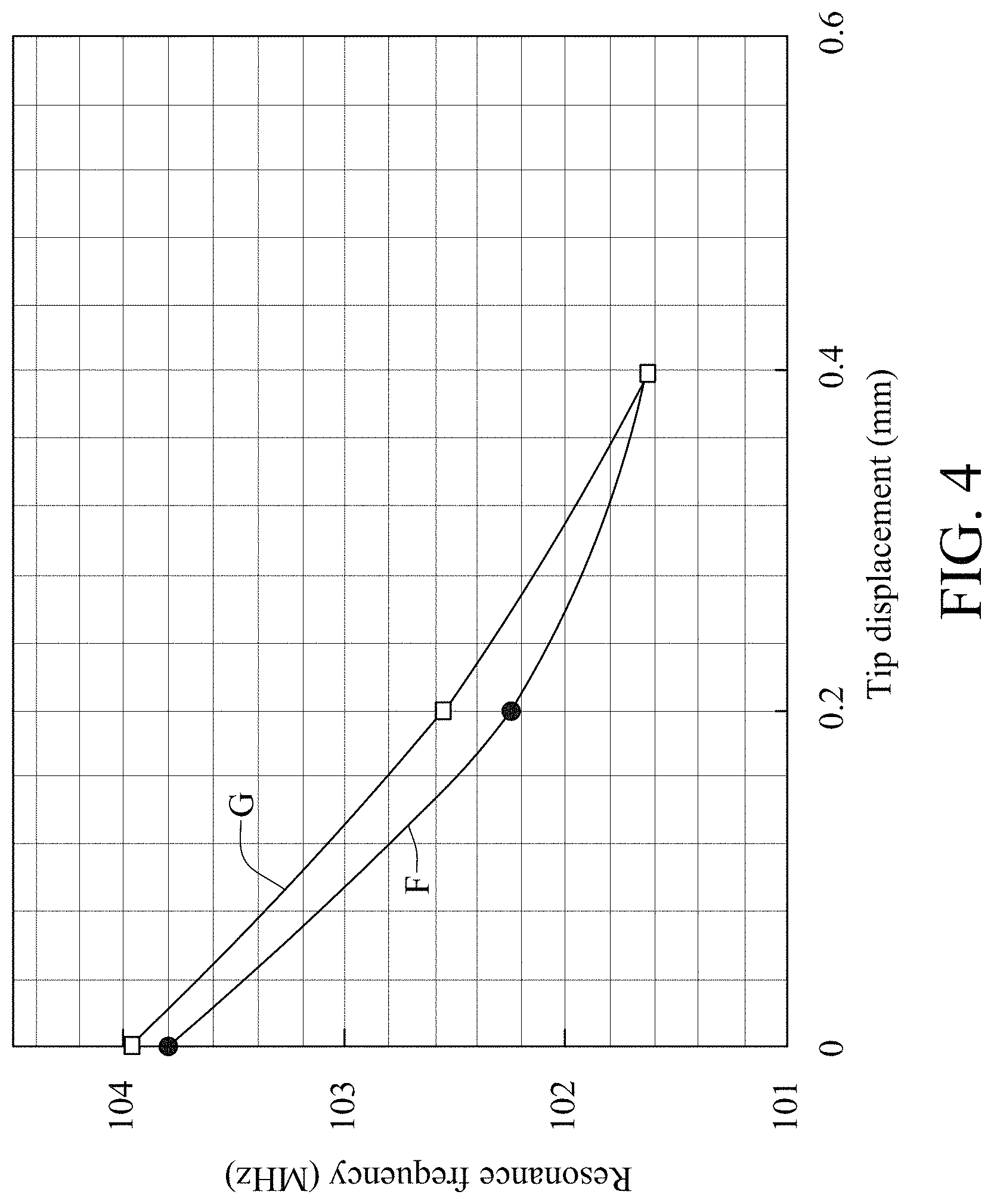
FIG. 4 is a schematic diagram showing the relationship between tip displacement and resonance frequency in a smart mechanical component of the present disclosure.
FIG. 5 is a schematic diagram showing the relationship between compression force and resonance frequency in a smart mechanical component of the present disclosure.
FIG. 6 is a sectional view of a smart mechanical component according to a second embodiment of the present disclosure.
FIG. 7 is a partial sectional view of the smart mechanical component according to the second embodiment of the present disclosure.
FIG. 8 is a schematic diagram showing the sign communication between a signal reader and the smart mechanical component of the second embodiment.
FIG. 9A is a sectional view of a smart mechanical component according to a third embodiment of the present disclosure.
FIG. 9B is a partial sectional view of a connecting unit used in the smart mechanical component of the third embodiment.
FIG. 10 is a schematic diagram showing the sign communication between a signal reader and the smart mechanical component of the third embodiment.
FIG. 11A is a sectional view of a smart mechanical component according to a fourth embodiment of the present disclosure.
FIG. 11B is a partial sectional view of the smart mechanical component according to the fourth embodiment of the present disclosure.
DETAILED DESCRIPTION
In the following detailed description, for purposes of explanation, numerous specific details are set forth in order to provide a thorough understanding of the disclosed embodiments. It will be apparent, however, that one or more embodiments may be practiced without these specific details. In other instances, well-known structures and devices are schematically shown in order to simplify the drawing.
Please refer to FIG. 1A and FIG. 1B, which are schematic diagrams showing a sectional view and a partial view of a smart mechanical component according to a first embodiment of the present disclosure. In FIG. 1A and FIG. 1B, a smart mechanical component is disclosed, which comprises: a main body 10, at least one connecting unit 11, and at least one secondary body 12.
The secondary body 12 is disposed inside the main body 10, while allowing a three-dimensional (3-D) reserved space 13 to be formed between the secondary body 12 and the main body 10. Thereby, the assembly of the main body 10, the secondary body 12 and the three-dimensional (3-D) reserved space 13 forms a capacitor. It is noted that main body 10 can be a screw or a bolt.
The connecting unit 11 is used for connecting the secondary body 12 to the main body 10, while allowing the connecting unit 11 to act like an inductor. By the cooperation between the aforesaid capacitor and the inductor, an LC circuit1 is achieved.
In this embodiment, the main body 10, the secondary body 12 and the connecting unit 11 are integrally formed or are laminated together. In addition, either there can be a film being formed on the surfaces of the main body 10, the secondary body 12 and the connecting unit 11, or it is possible to modify the material of the main body 10, the secondary body 12 and the connecting unit 11 for enhancing the their conductivity or structure strength.
Moreover, there can be a magnetic material disposed surrounding the secondary body 12, and also the three-dimensional (3-D) reserved space 13 can be filled or partially filled with a dielectric material. Operationally, the size of the three-dimensional (3-D) reserved space 13, that is, the distance measured between the secondary body 12 and the main body 10, is designed to be adjustable by the driving of an external force or by the use of an regulator.
In FIG. 2, a reader 20 is provided, which is composed of a frequency scanner and a radiofrequency coil and is used for reading the aforesaid LC circuit1. Operationally, when an external force 21 is exerted upon the main body 10, the reader 20 will be activated to fed an energy 22 to the LC circuit1 for enabling the LC circuit1 to response back a reflection energy 23 to be detected by the reader 20, and then the reader 20 is able to proceed with a signal process operation for obtaining a resonance frequency of the LC circuit1 while accordingly obtaining the deformation of the main body 10 or the magnitude of the external force 21.
In FIG. 3, Curve A represents the signals detected by the reader 20 when the reader 20 is not being positioned near the smart mechanical component, and consequently the corresponding reflection energy 23 may be too minute to be detected so that there can be no resonance frequency being detected and measured.
On the other hand, Curve E represents a situation that there is no external force 21 existed and the reader is positioned within a proper distance near the smart mechanical component with a tip displacement of 0 mm, by that the resonance frequency being detected is about 104 MHz.
Curve D represents another situation that there is an external force 21 existed and the reader is positioned within a proper distance near the smart mechanical component with a tip displacement of 0.2 mm, by that the resonance frequency being detected is about 102 MHz.
Curve C represents another situation that there is an external force 21 existed and the reader is positioned within a proper distance near the smart mechanical component with a tip displacement of 0.4 mm, by that the resonance frequency being detected is about 101.5 MHz.
Curve D represents another situation that there is an external force 21 existed and the reader is positioned within a proper distance near the smart mechanical component with a tip displacement of 0.6 mm, by that the resonance frequency is not detectable as the tip displacement is too large.
As disclosed in the aforesaid Curve A to Curve E, it can be concluded that the main body 10 is engaged with the secondary body 12 when the tip displacement is 0.6 mm as the so-formed capacitor is short-circuited for enabling the resonance frequency of the LC circuit1 to be destroyed. Thereby, the deformation of the smart mechanical component can be determined according to the variation of the resonance frequency or the short-circuit condition.
FIG. 4 is a schematic diagram showing the relationship between tip displacement and resonance frequency in a smart mechanical component of the present disclosure. As shown in the Curve A of FIG. 4, the tip displacement is increase with the increasing of a side-way external force, and correspondingly the resonance frequency is decreasing. On the other hand, Curve G shows that the tip displacement is decrease with the decreasing of the side-way external force, and correspondingly the resonance frequency is increasing.
FIG. 5 is a schematic diagram showing the relationship between compression force and resonance frequency in a smart mechanical component of the present disclosure. As shown in the Curve I of FIG. 5, the tip displacement is subjected to an increasing compression force, and correspondingly the resonance frequency is increasing with the increasing compression force, whereas the Curve H shows the vice versa.
Please refer to FIG. 6 and FIG. 7, which are schematic diagrams showing a sectional view and a partial view of a smart mechanical component according to a second embodiment of the present disclosure. In this second embodiment, the smart mechanical component is comprised of: a main body 30, at least one connecting unit 31 and a secondary body 32.
The secondary body 32 is disposed inside the main body 30 while allowing a three-dimensional (3-D) reserved space 33 to be formed between the main body 30 and the secondary body 32, and thereby a capacitor can be achieved from the assembly of the main body 30, the secondary body 32 and the three-dimensional (3-D) reserved space 33. In the second embodiment, the main body 30 is a hook.
The connecting unit 31 that is provided for connecting the secondary body 32 to the main body 30 is substantially an inductor itself that is to be used cooperatively with the aforesaid capacitor to construct an LC circuit3.
In FIG. 8, a reader is provided, which is composed of a frequency scanner 41 and a radiofrequency coil 42. The frequency scanner 41 is enabled to provide an energy 43 to the main body 30 via the radiofrequency coil 42. Operationally, when an external force 40 is exerted upon the main body 30, the reader 20 will be activated to fed the energy 43 to the LC circuit3 for enabling the LC circuit1 to response back a reflection energy 44 carrying resonance frequency information of the LC circuit3 to be detected by the frequency scanner 41 of the reader. Similar to those disclosed in FIG. 3 to FIG.5, the variation of resonance frequency that is disclosed in FIG. 6 also indicates that the smart mechanical component is deformed by the external force, and when the resonance frequency can no longer be detected, it represents that the deform of the smart mechanical component is too large that the smart mechanical component is damaged.
Please refer to FIG. 9A and FIG. 9B, which are schematic diagrams showing a sectional view and a partial view of a smart mechanical component according to a third embodiment of the present disclosure. In this third embodiment, the smart mechanical component is comprised of: a main body 50, at least one connecting unit 51 and a secondary body 52.
The secondary body 52 is disposed inside the main body 50 while allowing a three-dimensional (3-D) reserved space 53 to be formed between the main body 50 and the secondary body 52, and thereby a capacitor can be achieved from the assembly of the main body 50, the secondary body 52 and the three-dimensional (3-D) reserved space 53. In the third embodiment, the main body 50 is a screw rod or a slide rail.
The at least one connecting unit 51 that is provided for connecting the secondary body 52 to the main body 50 is connected to at least two ends of the main body 50. The reason why there is a need for more than one connecting units 51 is to maintain the overall structural integrity when the main body 50 is too long. Similarly, the at least one connecting unit 51 is substantially an inductor itself that is to be used cooperatively with the aforesaid capacitor to construct an LC circuit5.
In FIG. 10, there are two connecting units so that the so-achieved LC circuit5 is a circuit with two inductors. In FIG. 10, a reader is provided, which is composed of a frequency scanner 61 and a radiofrequency coil 62. The frequency scanner 61 is enabled to provide an energy 63 to the main body 50 via the radiofrequency coil 62. Operationally, when an external force 60 is exerted upon the main body 50, the reader will be activated to fed the energy 63 to the LC circuit5 for enabling the LC circuit5 to response back a reflection energy 64 carrying resonance frequency information of the LC circuit5 to be detected by the frequency scanner 61 of the reader. Similar to those disclosed in FIG. 3 to FIG.5, the variation of resonance frequency that is disclosed in FIG. 6 also indicates that the smart mechanical component is deformed by the external force, and when the resonance frequency can no longer be detected, it represents that the deform of the smart mechanical component is too large that the smart mechanical component is damaged.
Please refer to FIG. 11A and FIG. 11B, which are schematic diagrams showing a sectional view and a partial view of a smart mechanical component according to a fourth embodiment of the present disclosure. In this fourth embodiment, the smart mechanical component is comprised of: a main body 70, a connecting unit 71 and a secondary body 72.
The main body 70 is arranged boring through the secondary body 72, and the connecting unit 71 is provided for connecting the main body 70 to the secondary body 72. Similar, there is a three-dimensional (3-D) reserved space 73 formed at a position between the main body 70 and the secondary body 72, and thereby a capacitor can be achieved from the assembly of the main body 70, the secondary body 72 and the three-dimensional (3-D) reserved space 73. Moreover, the connecting unit 71 is substantially an inductor itself that is to be used cooperatively with the aforesaid capacitor to construct an LC circuit7. In this embodiment, the main body 70 is a peg, while the secondary body 72 can be a pad designed for the peg, and the connecting unit 71 can be a coil.
When the peg, i.e. the main body shown in the fourth embodiment of FIG. 11A, is fastened to the spine of a human body, the secondary body 72 is engaged to the main body 70, and thereby a short-circuit condition is caused for enabling the resonance frequency of the LC circuit7 to be destroyed. On the other hand, when the peg is loosened while allowing the main body 70 to disengage itself from the secondary body 72, the resonance frequency of the LC circuit7 is detectable. Consequently, the status of the peg relating to whether it is fastened or loosened can be detected and determined according to the measurement of the resonance frequency.
To sum up, the present disclosure provides a smart mechanical component capable of determining whether there is any of its parts is required to be replaced by the detection of a resonance effect from an inductor-capacitor (LC) circuit built inside the mechanical component.
With respect to the above description then, it is to be realized that the optimum dimensional relationships for the parts of the disclosure, to include variations in size, materials, shape, form, function and manner of operation, assembly and use, are deemed readily apparent and obvious to one skilled in the art, and all equivalent relationships to those illustrated in the drawings and described in the specification are intended to be encompassed by the present disclosure.
* * * * *
D00000
D00001
D00002
D00003
D00004
D00005
D00006
D00007
D00008
D00009
D00010
D00011
D00012
D00013
D00014

XML
uspto.report is an independent third-party trademark research tool that is not affiliated, endorsed, or sponsored by the United States Patent and Trademark Office (USPTO) or any other governmental organization. The information provided by uspto.report is based on publicly available data at the time of writing and is intended for informational purposes only.
While we strive to provide accurate and up-to-date information, we do not guarantee the accuracy, completeness, reliability, or suitability of the information displayed on this site. The use of this site is at your own risk. Any reliance you place on such information is therefore strictly at your own risk.
All official trademark data, including owner information, should be verified by visiting the official USPTO website at www.uspto.gov. This site is not intended to replace professional legal advice and should not be used as a substitute for consulting with a legal professional who is knowledgeable about trademark law.