Water injector for aviation cooling system
Army, Jr. , et al.
U.S. patent number 10,697,355 [Application Number 15/975,445] was granted by the patent office on 2020-06-30 for water injector for aviation cooling system. This patent grant is currently assigned to HAMILTON SUNSTRAND CORPORATION. The grantee listed for this patent is HAMILTON SUNDSTRAND CORPORATION. Invention is credited to Donald E. Army, Jr., Patrick McCord.

| United States Patent | 10,697,355 |
| Army, Jr. , et al. | June 30, 2020 |
Water injector for aviation cooling system
Abstract
A water injector for an aviation cooling system includes a body having a first end, a second end, and an intermediate portion extending therebetween. A conduit extends through the body from the first end to the second end. A spray nozzle is fluidically connected to the conduit and arranged at one of the first end and the second end. A mounting plate is arranged at the other of the first end and the second end. The mounting plate is configured and disposed to secure the body to an aviation cooling component. A filter is supported at the body and is fluidically exposed to the conduit. The filter is configured and disposed to capture particulate flowing into the water injector towards the spray nozzle.
| Inventors: | Army, Jr.; Donald E. (Enfield, CT), McCord; Patrick (Norwich, CT) | ||||||||||
|---|---|---|---|---|---|---|---|---|---|---|---|
| Applicant: |
|
||||||||||
| Assignee: | HAMILTON SUNSTRAND CORPORATION
(Charlotte, NC) |
||||||||||
| Family ID: | 55080023 | ||||||||||
| Appl. No.: | 15/975,445 | ||||||||||
| Filed: | May 9, 2018 |
Prior Publication Data
| Document Identifier | Publication Date | |
|---|---|---|
| US 20180258837 A1 | Sep 13, 2018 | |
Related U.S. Patent Documents
| Application Number | Filing Date | Patent Number | Issue Date | ||
|---|---|---|---|---|---|
| 14590558 | Jan 6, 2015 | 9988973 | |||
| Current U.S. Class: | 1/1 |
| Current CPC Class: | B05B 1/02 (20130101); B64D 13/08 (20130101); H05K 7/20881 (20130101); H05K 7/20345 (20130101); F02B 29/0462 (20130101); B05B 15/62 (20180201); B64D 2013/0614 (20130101); Y02T 10/146 (20130101); F24F 2006/146 (20130101); B64D 2013/0674 (20130101); B05B 15/40 (20180201); Y02T 10/12 (20130101) |
| Current International Class: | B05B 1/32 (20060101); B64D 13/08 (20060101); B05B 1/02 (20060101); H05K 7/20 (20060101); F02B 29/04 (20060101); B05B 15/62 (20180101); F24F 6/14 (20060101); B64D 13/06 (20060101); B05B 15/40 (20180101) |
| Field of Search: | ;239/541 |
References Cited [Referenced By]
U.S. Patent Documents
| 2385825 | October 1945 | Mathisen |
| 3101918 | August 1963 | Evelyn et al. |
| 3878692 | April 1975 | Steves |
| 4272014 | June 1981 | Halfpenny et al. |
| 4323191 | April 1982 | Chiyoda et al. |
| 4829775 | May 1989 | Defrancesco |
| 5168748 | December 1992 | Flora, Jr. |
| 5261243 | November 1993 | Dunsmore |
| 5299763 | April 1994 | Bescoby et al. |
| 5355670 | October 1994 | Sciocchetti |
| 6065301 | May 2000 | Akazawa |
| 6325362 | December 2001 | Massey et al. |
| 6739400 | May 2004 | Lessi et al. |
| 6921047 | July 2005 | McColgan et al. |
| 6971607 | December 2005 | McColgan et al. |
| 7434628 | October 2008 | Scheidt |
| 7523622 | April 2009 | Zywiak et al. |
| 8608106 | December 2013 | Baumgardt et al. |
| 2003/0082266 | May 2003 | Babin |
| 2003/0209613 | November 2003 | Miyauchi et al. |
| 2005/0139366 | June 2005 | Scheidt |
| 2008/0083543 | April 2008 | Joo |
| 2009/0078794 | March 2009 | Cheng |
| 2011/0247970 | October 2011 | Evingham |
| 2013/0118190 | May 2013 | Bruno et al. |
| 2013/0160472 | June 2013 | Klimpel et al. |
| 2013/0239598 | September 2013 | Barkowsky |
| 2013/0273009 | October 2013 | Bridger et al. |
| 2014/0116966 | May 2014 | Podsadowski |
| 2016/0195004 | July 2016 | Army, Jr. et al. |
| 202667021 | Jan 2013 | CN | |||
| 0035909 | Sep 1981 | EP | |||
| 753194 | Jul 1956 | GB | |||
| 1-218999 | Sep 1989 | JP | |||
| 3-11200 | Feb 1991 | JP | |||
| 4-3195 | Jan 1992 | JP | |||
| 4-227410 | Aug 1992 | JP | |||
| 6-277418 | Oct 1994 | JP | |||
| 2005185835 | Jul 2005 | JP | |||
Other References
|
European Search Report for Application No. 16150146.5-1760 dated Jun. 7, 2016; 7 pages. cited by applicant . Japanese Patent Office, Notice of Reasons for Rejection, for Patent Application No. 2016-000767, dated Jun. 18, 2019 (8 pp). cited by applicant . Japanese Patent Office, Notice of Reasons for Rejection, Patent Application No. JP2016-000767, dated Jan. 7, 2020 (9 pp.). cited by applicant. |
Primary Examiner: Hwu; Davis D
Attorney, Agent or Firm: Cantor Colburn LLP
Claims
What is claimed is:
1. A water injector for an aviation cooling system comprising: a body having a first end, a second end longitudinally spaced along a longitudinal axis from the first end, and an intermediate portion extending therebetween, the intermediate portion extending longitudinally along the longitudinal axis; a conduit extending along the longitudinal axis through the body from the first end to the second end; a spray nozzle fluidically connected to the conduit arranged at one of the first end and the second end, the spray nozzle extending along the longitudinal axis and being threadingly connected to the body in a repeatedly removable manner; a mounting plate arranged at the other of the first end and the second end, the mounting plate being extending substantially perpendicularly to the longitudinal axis and being configured and disposed to secure the body to an aviation cooling component; and a filter supported in a filter body at the body and fluidically exposed to the conduit, the filter being configured and disposed to capture particulate flowing into the water injector towards the spray nozzle, the filter body extending along the longitudinal axis and being threadingly engaged in the other of the first end and the second end in a repeatedly removable manner.
2. The water injector according to claim 1, wherein the spray nozzle includes an orifice having an outlet of less than about 0.120-inches (3.05-mm).
3. The water injector according to claim 1, further comprising: a sealing gasket arranged at the mounting plate, the sealing gasket being configured and disposed to seal an interface between the water injector and the aviation cooling component.
4. The water injector of claim 1, wherein the mounting plate includes a sealing gasket on a side of the mounting plate that faces the one of the first end and the second end.
5. The water injector of claim 1, wherein the filter body includes a threaded end, an outlet longitudinally aligned along the longitudinal axis with the threaded end and an inlet end at an opposing end, the inlet end configured to connect with a fluid line to collect water from a water collector.
6. The water injector of claim 5, wherein the threaded end of the filter body is longitudinally aligned along the longitudinal axis with the mounting plate.
Description
CROSS-REFERENCE TO RELATED APPLICATIONS
This application claims the benefit of U.S. patent application Ser. No. 14/590,558, filed Jan. 6, 2015, which is incorporated herein by reference in its entirety.
BACKGROUND
Exemplary embodiments pertain to the art of aviation cooling systems and, more particularly to a water injector for an aviation cooling system.
Many commercial/military aircraft include cooling systems that are designed to remove heat from various systems such as electronic components. Generally, the cooling systems include multiple components including a heat exchanger, a condenser, a water extractor, and a system for moving a coolant through the components. In some cases, water is channeled from the water extractor to the heat exchanger. The water is directed through an injector onto a surface of the heat exchanger to enhance cooling.
BRIEF DESCRIPTION
Disclosed is a water injector for an aviation cooling system including a body having a first end, a second end, and an intermediate portion extending therebetween. A conduit extends through the body from the first end to the second end. A spray nozzle is fluidically connected to the conduit and arranged at one of the first end and the second end. A mounting plate is arranged at the other of the first end and the second end. The mounting plate is configured and disposed to secure the body to an aviation cooling component. A filter is supported at the body and fluidically exposed to the conduit. The filter is configured and disposed to capture particulate flowing into the water injector towards the spray nozzle.
BRIEF DESCRIPTION OF THE DRAWINGS
The following descriptions should not be considered limiting in any way. With reference to the accompanying drawings, like elements are numbered alike:
FIG. 1 is a schematic view of an aviation cooling system including a water injector, in accordance with an exemplary embodiment; and
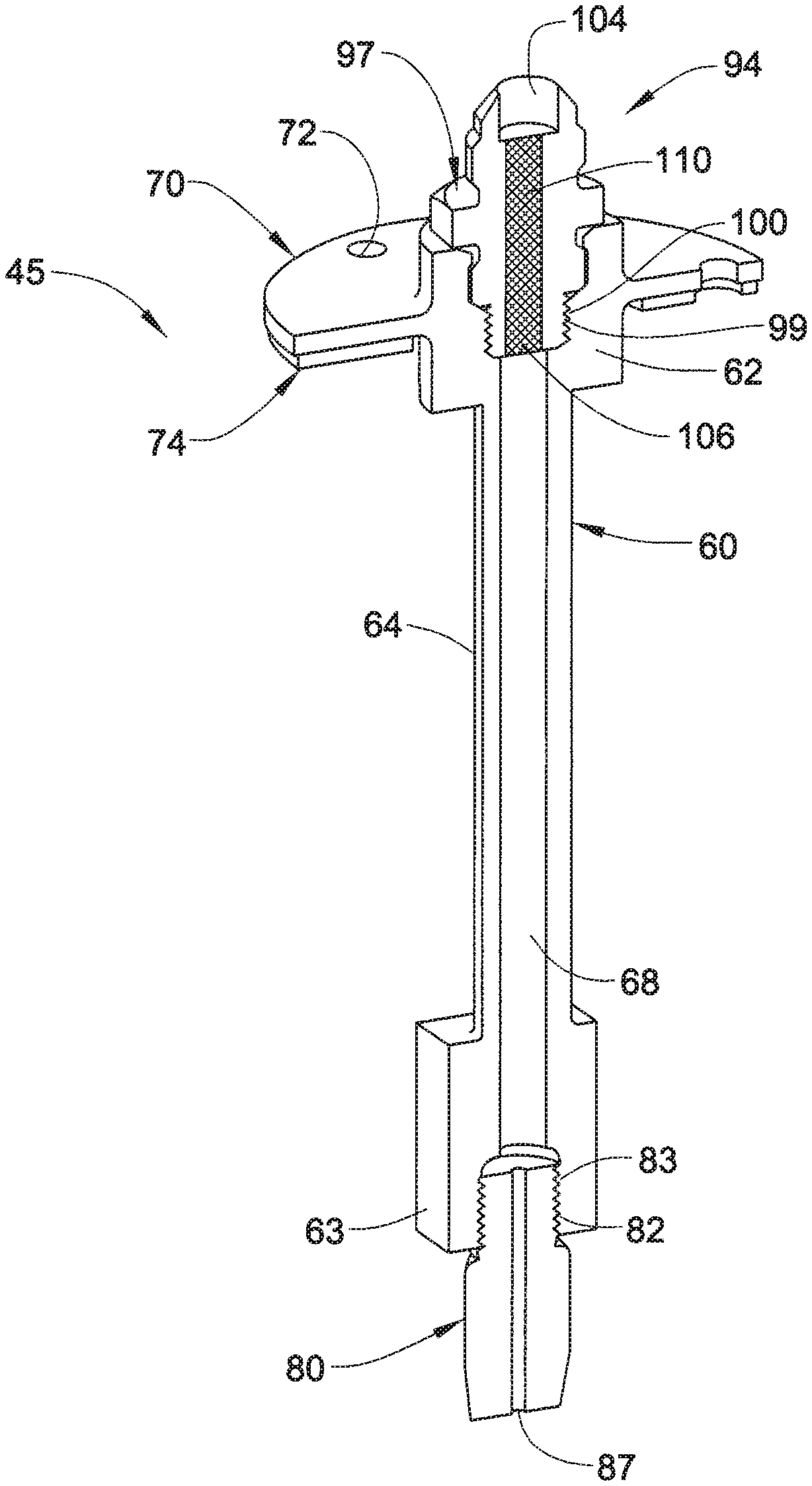
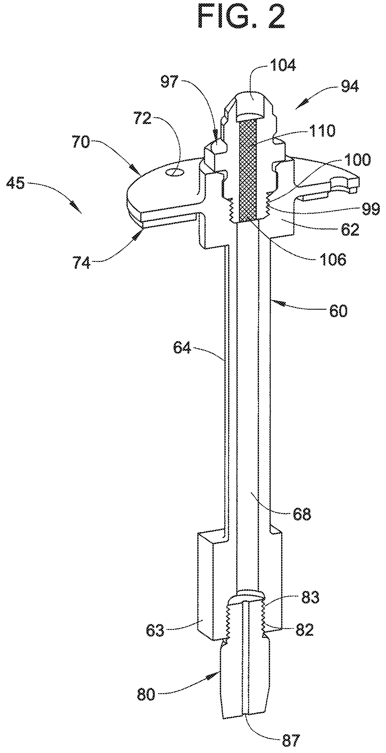
FIG. 2 is a partial cross-sectional view of the water injector of FIG. 1.
DETAILED DESCRIPTION
A detailed description of one or more embodiments of the disclosed apparatus and method are presented herein by way of exemplification and not limitation with reference to the Figures.
An aviation cooling system, in accordance with an exemplary embodiment, is illustrated generally at 2, in FIG. 1. Aviation cooling system 2 includes a bleed air inlet 4 and a conditioned air outlet 6. Aviation cooling system 2 may be employed in a commercial passenger aircraft, a military aircraft, or the like. As such, conditioned air outlet 6 could be directed towards one or more avionics systems. Of course, it should be understood that aviation cooling system 2 may be employed to condition other aviation components as well as cockpit and/or cabin air.
Aviation cooling system 2 includes a ram air heat exchanger 10 including a ram air header 12 having a ram air inlet 14. Ram air heat exchanger 10 also includes a ram air outlet 16. A condenser 30 is operatively connected to ram air heat exchanger 10 through a fluid line 32. Another fluid line 34 operatively connects condenser 30 back to ram air heat exchanger 10. A pump or compressor (not shown) may be fluidically connected to one of fluid lines 32 and 34 to circulate a coolant or refrigerant through aviation cooling system 2. Condenser 30 is also fluidically connected to a water collector 39 via a fluid line 42. Water collector 39 is fluidically connected to a first water injector 45 and a second water injector 47 via a fluid line 50. First and second water injectors 45 and 47 deliver jets of water onto ram air heat exchanger 10 to enhance conditioning of air passing into bleed air inlet 4.
Reference will now follow to FIG. 2 in describing water injector 45 with an understanding that water injector 47 may include similar structure. Water injector 45 includes a body 60 having a first end 62, a second end 63, and an intermediate portion 64 extending therebetween. A conduit 68 extends through body 60 from first end 62 to second end 63. Water injector 45 includes a mounting plate 70 arranged at first end 62. Mounting plate 70 includes a plurality of openings, one of which is indicated at 72, which receive mechanical fasteners (not shown) that secure water injector 45 to ram air header 12. A sealing gasket 74 is arranged at mounting plate 70. Sealing gasket 74 restricts leakage from ram air header 12.
Water injector 45 also includes a spray nozzle 80 arranged at second end 63. Spray nozzle 80 includes a threaded portion 82 that engages with a threaded section 83 formed at second end 63. Spray nozzle 80 includes an orifice 85 having an outlet 87. Outlet 87 includes a diameter of less than about 0.120-inches (3.05-mm). As such, outlet 87 may clog in the event debris may be carried in water from water collector 39. In accordance with an exemplary embodiment, water injector 45 includes a filter 94 arranged at first end 62. Filter 94 includes a filter body 97 having a threaded zone 99 that engages with a threaded section 100 at first end 62. Filter 94 also includes an inlet 104, an outlet 106, and an amount of filter media 110 arranged therebetween. Inlet 104 connects with fluid line 50 to receive water from water collector 39. The water passes through filter media 110 and through outlet 87 of orifice 85 to be sprayed onto ram air heat exchanger 10. The addition of filter media 110 reduces clogs at orifice 85. Further, filter 94 is easily accessed for service and replacement.
The term "about" is intended to include the degree of error associated with measurement of the particular quantity based upon the equipment available at the time of filing the application.
The terminology used herein is for the purpose of describing particular embodiments only and is not intended to be limiting of the present disclosure. As used herein, the singular forms "a", "an" and "the" are intended to include the plural forms as well, unless the context clearly indicates otherwise. It will be further understood that the terms "comprises" and/or "comprising," when used in this specification, specify the presence of stated features, integers, steps, operations, elements, and/or components, but do not preclude the presence or addition of one or more other features, integers, steps, operations, element components, and/or groups thereof.
While the invention has been described with reference to an exemplary embodiment or embodiments, it will be understood by those skilled in the art that various changes may be made and equivalents may be substituted for elements thereof without departing from the scope of the invention. In addition, many modifications may be made to adapt a particular situation or material to the teachings of the invention without departing from the essential scope thereof. Therefore, it is intended that the invention not be limited to the particular embodiment disclosed as the best mode contemplated for carrying out this invention, but that the invention will include all embodiments falling within the scope of the claims.
* * * * *
D00000
D00001
D00002
XML
uspto.report is an independent third-party trademark research tool that is not affiliated, endorsed, or sponsored by the United States Patent and Trademark Office (USPTO) or any other governmental organization. The information provided by uspto.report is based on publicly available data at the time of writing and is intended for informational purposes only.
While we strive to provide accurate and up-to-date information, we do not guarantee the accuracy, completeness, reliability, or suitability of the information displayed on this site. The use of this site is at your own risk. Any reliance you place on such information is therefore strictly at your own risk.
All official trademark data, including owner information, should be verified by visiting the official USPTO website at www.uspto.gov. This site is not intended to replace professional legal advice and should not be used as a substitute for consulting with a legal professional who is knowledgeable about trademark law.