Method and system for service switching using service tags
Jain , et al.
U.S. patent number 10,693,782 [Application Number 15/973,487] was granted by the patent office on 2020-06-23 for method and system for service switching using service tags. This patent grant is currently assigned to NICIRA, INC.. The grantee listed for this patent is Nicira, Inc.. Invention is credited to Jayant Jain, Anirban Sengupta.


| United States Patent | 10,693,782 |
| Jain , et al. | June 23, 2020 |
Method and system for service switching using service tags
Abstract
The disclosure herein describes a system, which provides service switching in a datacenter environment. The system can include a service switching gateway, which can identify a service tag associated with a received packet. During operation, the service switching gateway determines a source client, a requested service, or both for the packet based on the service tag, identifies a corresponding service portal based on the service tag, and forwards the packet toward the service portal. The service switching gateway can optionally maintain a mapping between the service tag and one or more of: a source client, a required service, the service portal, and a tunnel encapsulation. The service switching gateway can encapsulate the packet based on an encapsulation mechanism supported by the service portal and forward the packet based on the mapping.
| Inventors: | Jain; Jayant (Cupertino, CA), Sengupta; Anirban (Saratoga, CA) | ||||||||||
|---|---|---|---|---|---|---|---|---|---|---|---|
| Applicant: |
|
||||||||||
| Assignee: | NICIRA, INC. (Palo Alto,
CA) |
||||||||||
| Family ID: | 50943549 | ||||||||||
| Appl. No.: | 15/973,487 | ||||||||||
| Filed: | May 7, 2018 |
Prior Publication Data
| Document Identifier | Publication Date | |
|---|---|---|
| US 20180262427 A1 | Sep 13, 2018 | |
Related U.S. Patent Documents
| Application Number | Filing Date | Patent Number | Issue Date | ||
|---|---|---|---|---|---|
| 14960441 | Dec 7, 2015 | 9979641 | |||
| 13891025 | Dec 29, 2015 | 9225638 | |||
| Current U.S. Class: | 1/1 |
| Current CPC Class: | H04L 49/20 (20130101); H04L 45/306 (20130101); H04L 67/10 (20130101); H04L 45/74 (20130101); H04L 12/4633 (20130101); H04L 2212/00 (20130101); H04L 12/4641 (20130101) |
| Current International Class: | H04L 12/741 (20130101); H04L 12/725 (20130101); H04L 29/08 (20060101); H04L 12/931 (20130101); H04L 12/46 (20060101) |
| Field of Search: | ;370/389 |
References Cited [Referenced By]
U.S. Patent Documents
| 6006264 | December 1999 | Colby et al. |
| 6104700 | August 2000 | Haddock et al. |
| 6154448 | November 2000 | Petersen et al. |
| 6772211 | August 2004 | Lu et al. |
| 6880089 | April 2005 | Bommareddy et al. |
| 6985956 | January 2006 | Luke et al. |
| 7013389 | March 2006 | Srivastava et al. |
| 7209977 | April 2007 | Acharya et al. |
| 7239639 | July 2007 | Cox et al. |
| 7379465 | May 2008 | Aysan et al. |
| 7406540 | July 2008 | Acharya et al. |
| 7447775 | November 2008 | Zhu et al. |
| 7480737 | January 2009 | Chauffour et al. |
| 7487250 | February 2009 | Siegel |
| 7649890 | January 2010 | Mizutani et al. |
| 7818452 | October 2010 | Matthews et al. |
| 7898959 | March 2011 | Arad |
| 7948986 | May 2011 | Ghosh et al. |
| 8078903 | December 2011 | Parthasarathy et al. |
| 8175863 | May 2012 | Ostermeyer et al. |
| 8190767 | May 2012 | Maufer et al. |
| 8201219 | June 2012 | Jones |
| 8223634 | July 2012 | Tanaka et al. |
| 8230493 | July 2012 | Davidson et al. |
| 8266261 | September 2012 | Akagi |
| 8451735 | May 2013 | Li |
| 8484348 | July 2013 | Subramanian et al. |
| 8521879 | August 2013 | Pena et al. |
| 8615009 | December 2013 | Ramamoorthi |
| 8743885 | June 2014 | Khan et al. |
| 8811412 | August 2014 | Shippy |
| 8830834 | September 2014 | Sharma |
| 8832683 | September 2014 | Heim |
| 8849746 | September 2014 | Candea et al. |
| 8856518 | October 2014 | Sridharan et al. |
| 8862883 | October 2014 | Cherukuri |
| 8868711 | October 2014 | Skjolsvold et al. |
| 8873399 | October 2014 | Bothos et al. |
| 8892706 | November 2014 | Dalal |
| 8914406 | December 2014 | Haugsnes et al. |
| 8971345 | March 2015 | McCanne |
| 8989192 | March 2015 | Foo |
| 8996610 | March 2015 | Sureshchandra et al. |
| 9094464 | July 2015 | Scharber et al. |
| 9104497 | August 2015 | Mortazavi |
| 9148367 | September 2015 | Kandaswamy et al. |
| 9191293 | November 2015 | Iovene et al. |
| 9225638 | December 2015 | Jain et al. |
| 9225659 | December 2015 | McCanne |
| 9232342 | January 2016 | Seed et al. |
| 9264313 | February 2016 | Manuguri et al. |
| 9277412 | March 2016 | Freda et al. |
| 9397946 | July 2016 | Yadav |
| 9407599 | August 2016 | Koponen et al. |
| 9479358 | October 2016 | Klosowski et al. |
| 9503530 | November 2016 | Niedzielski |
| 9531590 | December 2016 | Jain et al. |
| 9602380 | March 2017 | Strassner |
| 9686192 | June 2017 | Sengupta et al. |
| 9686200 | June 2017 | Pettit et al. |
| 9705702 | July 2017 | Foo |
| 9755898 | September 2017 | Jain et al. |
| 9755971 | September 2017 | Wang et al. |
| 9774537 | September 2017 | Jain et al. |
| 9787605 | October 2017 | Zhang et al. |
| 9804797 | October 2017 | Ng et al. |
| 9825810 | November 2017 | Jain et al. |
| 9860079 | January 2018 | Cohn et al. |
| 9900410 | February 2018 | Dalal |
| 9935827 | April 2018 | Jain et al. |
| 9979641 | May 2018 | Jain et al. |
| 9985896 | May 2018 | Koponen et al. |
| 10075470 | September 2018 | Vaidya et al. |
| 10079779 | September 2018 | Zhang et al. |
| 10104169 | October 2018 | Moniz et al. |
| 10129077 | November 2018 | Jain et al. |
| 10129180 | November 2018 | Zhang et al. |
| 10135737 | November 2018 | Jain et al. |
| 10212071 | February 2019 | Kancherla et al. |
| 10225137 | March 2019 | Jain et al. |
| 10257095 | April 2019 | Jain et al. |
| 10320679 | June 2019 | Jain et al. |
| 10341233 | July 2019 | Jain et al. |
| 2002/0097724 | July 2002 | Halme et al. |
| 2002/0194350 | December 2002 | Lu et al. |
| 2003/0065711 | April 2003 | Acharya et al. |
| 2003/0093481 | May 2003 | Mitchell et al. |
| 2003/0097429 | May 2003 | Wu et al. |
| 2003/0105812 | June 2003 | Flowers et al. |
| 2003/0236813 | December 2003 | Abjanic |
| 2004/0066769 | April 2004 | Ahmavaara et al. |
| 2004/0210670 | October 2004 | Anerousis et al. |
| 2004/0215703 | October 2004 | Song et al. |
| 2005/0091396 | April 2005 | Nilakantan et al. |
| 2005/0114429 | May 2005 | Caccavale |
| 2005/0132030 | June 2005 | Hopen et al. |
| 2005/0198200 | September 2005 | Subramanian et al. |
| 2005/0249199 | November 2005 | Albert et al. |
| 2006/0069776 | March 2006 | Shim et al. |
| 2006/0130133 | June 2006 | Andreev et al. |
| 2006/0155862 | July 2006 | Kathi et al. |
| 2006/0233155 | October 2006 | Srivastava |
| 2007/0061492 | March 2007 | Riel |
| 2007/0214282 | September 2007 | Sen |
| 2007/0288615 | December 2007 | Keohane et al. |
| 2008/0005293 | January 2008 | Bhargava et al. |
| 2008/0031263 | February 2008 | Ervin et al. |
| 2008/0046400 | February 2008 | Shi et al. |
| 2008/0049614 | February 2008 | Briscoe et al. |
| 2008/0049619 | February 2008 | Twiss |
| 2008/0049786 | February 2008 | Ram et al. |
| 2008/0072305 | March 2008 | Casado et al. |
| 2008/0084819 | April 2008 | Parizhsky et al. |
| 2008/0104608 | May 2008 | Hyser et al. |
| 2008/0195755 | August 2008 | Lu et al. |
| 2008/0225714 | September 2008 | Denis |
| 2008/0239991 | October 2008 | Applegate et al. |
| 2008/0247396 | October 2008 | Hazard |
| 2008/0276085 | November 2008 | Davidson et al. |
| 2008/0279196 | November 2008 | Friskney et al. |
| 2009/0019135 | January 2009 | Eswaran et al. |
| 2009/0063706 | March 2009 | Goldman et al. |
| 2009/0129271 | May 2009 | Ramankutty et al. |
| 2009/0172666 | July 2009 | Yahalom et al. |
| 2009/0199268 | August 2009 | Ahmavaara et al. |
| 2009/0235325 | September 2009 | Dimitrakos et al. |
| 2009/0265467 | October 2009 | Peles et al. |
| 2009/0299791 | December 2009 | Blake et al. |
| 2009/0300210 | December 2009 | Ferris |
| 2009/0303880 | December 2009 | Maltz et al. |
| 2009/0307334 | December 2009 | Maltz et al. |
| 2009/0327464 | December 2009 | Archer et al. |
| 2010/0031360 | February 2010 | Seshadri et al. |
| 2010/0036903 | February 2010 | Ahmad et al. |
| 2010/0100616 | April 2010 | Bryson |
| 2010/0131638 | May 2010 | Kondamuru |
| 2010/0223364 | September 2010 | Wei |
| 2010/0223621 | September 2010 | Joshi et al. |
| 2010/0235915 | September 2010 | Memon et al. |
| 2010/0265824 | October 2010 | Chao et al. |
| 2010/0281482 | November 2010 | Pike et al. |
| 2010/0332595 | December 2010 | Fullagar et al. |
| 2011/0010578 | January 2011 | Dominguez et al. |
| 2011/0016348 | January 2011 | Pace et al. |
| 2011/0022695 | January 2011 | Dalal et al. |
| 2011/0022812 | January 2011 | Van Der Linden et al. |
| 2011/0035494 | February 2011 | Pandey et al. |
| 2011/0040893 | February 2011 | Karaoguz et al. |
| 2011/0055845 | March 2011 | Nandagopal et al. |
| 2011/0090912 | April 2011 | Shippy |
| 2011/0164504 | July 2011 | Bothos et al. |
| 2011/0211463 | September 2011 | Matityahu et al. |
| 2011/0225293 | September 2011 | Rathod |
| 2011/0235508 | September 2011 | Goel et al. |
| 2011/0261811 | October 2011 | Battestilli et al. |
| 2011/0268118 | November 2011 | Schlansker et al. |
| 2011/0276695 | November 2011 | Maldaner |
| 2011/0283013 | November 2011 | Grosser et al. |
| 2011/0295991 | December 2011 | Aida |
| 2011/0317708 | December 2011 | Clark |
| 2012/0005265 | January 2012 | Ushioda et al. |
| 2012/0014386 | January 2012 | Xiong et al. |
| 2012/0023231 | January 2012 | Ueno |
| 2012/0054266 | March 2012 | Kazerani et al. |
| 2012/0089664 | April 2012 | Igelka |
| 2012/0137004 | May 2012 | Smith |
| 2012/0140719 | June 2012 | Hui et al. |
| 2012/0144014 | June 2012 | Natham et al. |
| 2012/0147894 | June 2012 | Mulligan et al. |
| 2012/0155266 | June 2012 | Patel et al. |
| 2012/0185588 | July 2012 | Error |
| 2012/0207174 | August 2012 | Shieh |
| 2012/0230187 | September 2012 | Tremblay et al. |
| 2012/0239804 | September 2012 | Liu et al. |
| 2012/0246637 | September 2012 | Kreeger et al. |
| 2012/0281540 | November 2012 | Khan et al. |
| 2012/0287789 | November 2012 | Aybay et al. |
| 2012/0303784 | November 2012 | Zisapel et al. |
| 2012/0303809 | November 2012 | Patel et al. |
| 2012/0317260 | December 2012 | Husain et al. |
| 2012/0317570 | December 2012 | Dalcher et al. |
| 2012/0331188 | December 2012 | Riordan et al. |
| 2013/0003735 | January 2013 | Chao et al. |
| 2013/0039218 | February 2013 | Narasimhan et al. |
| 2013/0044636 | February 2013 | Koponen et al. |
| 2013/0058346 | March 2013 | Sridharan et al. |
| 2013/0073743 | March 2013 | Ramasamy et al. |
| 2013/0125120 | May 2013 | Zhang et al. |
| 2013/0136126 | May 2013 | Wang et al. |
| 2013/0142048 | June 2013 | Gross, IV et al. |
| 2013/0148505 | June 2013 | Koponen et al. |
| 2013/0151661 | June 2013 | Koponen et al. |
| 2013/0160024 | June 2013 | Shtilman et al. |
| 2013/0163594 | June 2013 | Sharma et al. |
| 2013/0166703 | June 2013 | Hammer et al. |
| 2013/0170501 | July 2013 | Egi et al. |
| 2013/0201989 | August 2013 | Hu et al. |
| 2013/0227097 | August 2013 | Yasuda et al. |
| 2013/0227550 | August 2013 | Weinstein et al. |
| 2013/0287026 | October 2013 | Davie |
| 2013/0311637 | November 2013 | Kamath et al. |
| 2013/0318219 | November 2013 | Kancherla |
| 2013/0332983 | December 2013 | Koorevaar et al. |
| 2013/0343378 | December 2013 | Veteikis et al. |
| 2014/0059204 | February 2014 | Nguyen et al. |
| 2014/0059544 | February 2014 | Koganty et al. |
| 2014/0068602 | March 2014 | Gember et al. |
| 2014/0092738 | April 2014 | Grandhi et al. |
| 2014/0092914 | April 2014 | Kondapalli |
| 2014/0101226 | April 2014 | Khandekar et al. |
| 2014/0115578 | April 2014 | Cooper et al. |
| 2014/0129715 | May 2014 | Mortazavi |
| 2014/0164477 | June 2014 | Springer et al. |
| 2014/0169168 | June 2014 | Jalan et al. |
| 2014/0169375 | June 2014 | Khan et al. |
| 2014/0195666 | July 2014 | Dumitriu et al. |
| 2014/0207968 | July 2014 | Kumar et al. |
| 2014/0254374 | September 2014 | Janakiraman et al. |
| 2014/0281029 | September 2014 | Danforth |
| 2014/0282526 | September 2014 | Basavaiah et al. |
| 2014/0301388 | October 2014 | Jagadish et al. |
| 2014/0304231 | October 2014 | Kamath et al. |
| 2014/0307744 | October 2014 | Dunbar et al. |
| 2014/0310391 | October 2014 | Sorenson et al. |
| 2014/0310418 | October 2014 | Sorenson et al. |
| 2014/0317677 | October 2014 | Vaidya et al. |
| 2014/0330983 | November 2014 | Zisapel et al. |
| 2014/0334485 | November 2014 | Jain et al. |
| 2014/0351452 | November 2014 | Bosch et al. |
| 2014/0362705 | December 2014 | Pan |
| 2014/0369204 | December 2014 | Anand et al. |
| 2014/0372567 | December 2014 | Ganesh et al. |
| 2014/0372616 | December 2014 | Arisoylu et al. |
| 2014/0372702 | December 2014 | Subramanyam et al. |
| 2015/0003453 | January 2015 | Sengupta et al. |
| 2015/0003455 | January 2015 | Haddad et al. |
| 2015/0009995 | January 2015 | Gross, IV et al. |
| 2015/0026345 | January 2015 | Ravinoothala et al. |
| 2015/0030024 | January 2015 | Venkataswami et al. |
| 2015/0052262 | February 2015 | Chanda et al. |
| 2015/0063364 | March 2015 | Thakkar et al. |
| 2015/0071301 | March 2015 | Dalal |
| 2015/0124840 | May 2015 | Bergeron |
| 2015/0146539 | May 2015 | Mehta et al. |
| 2015/0156035 | June 2015 | Foo |
| 2015/0188770 | July 2015 | Naiksatam et al. |
| 2015/0213087 | July 2015 | Sikri |
| 2015/0215819 | July 2015 | Bosch et al. |
| 2015/0222640 | August 2015 | Kumar et al. |
| 2015/0280959 | October 2015 | Vincent |
| 2015/0281089 | October 2015 | Marchetti |
| 2015/0281098 | October 2015 | Pettit et al. |
| 2015/0281125 | October 2015 | Koponen et al. |
| 2015/0288679 | October 2015 | Ben-Nun et al. |
| 2015/0372840 | December 2015 | Benny et al. |
| 2015/0372911 | December 2015 | Yabusaki et al. |
| 2015/0381494 | December 2015 | Cherian et al. |
| 2015/0381495 | December 2015 | Cherian et al. |
| 2016/0028640 | January 2016 | Zhang et al. |
| 2016/0043901 | February 2016 | Sankar et al. |
| 2016/0057050 | February 2016 | Ostrom et al. |
| 2016/0087888 | March 2016 | Jain et al. |
| 2016/0094384 | March 2016 | Jain et al. |
| 2016/0094389 | March 2016 | Jain et al. |
| 2016/0094451 | March 2016 | Jain et al. |
| 2016/0094452 | March 2016 | Jain et al. |
| 2016/0094453 | March 2016 | Jain et al. |
| 2016/0094454 | March 2016 | Jain et al. |
| 2016/0094455 | March 2016 | Jain et al. |
| 2016/0094456 | March 2016 | Jain et al. |
| 2016/0094457 | March 2016 | Jain et al. |
| 2016/0094631 | March 2016 | Jain et al. |
| 2016/0094632 | March 2016 | Jain et al. |
| 2016/0094633 | March 2016 | Jain et al. |
| 2016/0094642 | March 2016 | Jain et al. |
| 2016/0094643 | March 2016 | Jain et al. |
| 2016/0094661 | March 2016 | Jain et al. |
| 2016/0134528 | May 2016 | Lin et al. |
| 2016/0149816 | May 2016 | Roach et al. |
| 2016/0164787 | June 2016 | Roach et al. |
| 2016/0226700 | August 2016 | Zhang et al. |
| 2016/0226754 | August 2016 | Zhang et al. |
| 2016/0226762 | August 2016 | Zhang et al. |
| 2016/0277210 | September 2016 | Lin et al. |
| 2016/0294612 | October 2016 | Ravinoothala et al. |
| 2016/0294933 | October 2016 | Hong et al. |
| 2016/0294935 | October 2016 | Hong et al. |
| 2016/0308758 | October 2016 | Li et al. |
| 2016/0352866 | December 2016 | Gupta et al. |
| 2016/0366046 | December 2016 | Anantharam et al. |
| 2017/0005920 | January 2017 | Previdi et al. |
| 2017/0005988 | January 2017 | Bansal et al. |
| 2017/0063683 | March 2017 | Li et al. |
| 2017/0063928 | March 2017 | Jain et al. |
| 2017/0126497 | May 2017 | Dubey et al. |
| 2017/0142012 | May 2017 | Thakkar et al. |
| 2017/0149582 | May 2017 | Cohn et al. |
| 2017/0149675 | May 2017 | Yang |
| 2017/0230467 | August 2017 | Salgueiro et al. |
| 2017/0295100 | October 2017 | Hira et al. |
| 2017/0310588 | October 2017 | Zuo |
| 2017/0317954 | November 2017 | Masurekar et al. |
| 2017/0364794 | December 2017 | Mahkonen et al. |
| 2017/0373990 | December 2017 | Jeuk et al. |
| 2018/0091420 | March 2018 | Drake et al. |
| 2018/0124061 | May 2018 | Raman et al. |
| 2018/0145899 | May 2018 | Rao |
| 2018/0159733 | June 2018 | Poon et al. |
| 2018/0159943 | June 2018 | Poon et al. |
| 2018/0198692 | July 2018 | Ansari et al. |
| 2018/0213040 | July 2018 | Pak et al. |
| 2018/0234360 | August 2018 | Narayana et al. |
| 2018/0248986 | August 2018 | Dalal |
| 2018/0262434 | September 2018 | Koponen et al. |
| 2018/0278530 | September 2018 | Connor et al. |
| 2018/0302242 | October 2018 | Hao et al. |
| 2019/0020600 | January 2019 | Zhang et al. |
| 2019/0068500 | February 2019 | Hira |
| 2019/0132220 | May 2019 | Boutros et al. |
| 2019/0132221 | May 2019 | Boutros et al. |
| 2019/0149512 | May 2019 | Sevinc et al. |
| 2019/0229937 | July 2019 | Nagarajan et al. |
| 2019/0238363 | August 2019 | Boutros et al. |
| 2019/0238364 | August 2019 | Boutros et al. |
| 1689369 | Oct 2005 | CN | |||
| 101729412 | Jun 2010 | CN | |||
| 103516807 | Jan 2014 | CN | |||
| 103795805 | May 2014 | CN | |||
| 2426956 | Mar 2012 | EP | |||
| 2005311863 | Nov 2005 | JP | |||
| 9918534 | Apr 1999 | WO | |||
| 2008095010 | Aug 2008 | WO | |||
| 2014182529 | Nov 2014 | WO | |||
| 2016053373 | Apr 2016 | WO | |||
| 2016054272 | Apr 2016 | WO | |||
| 2019084066 | May 2019 | WO | |||
| 2019147316 | Aug 2019 | WO | |||
Other References
|
PCT International Search Report and Written Opinion dated Sep. 25, 2014 for commonly owned International Patent Application PCT/US14/036275, 10 pages, VMware, Inc. cited by applicant . Author Unknown, "Datagram," Jun. 22, 2012, 2 pages, retrieved from https://web.archive.org/web/20120622031055/https://en.wikipedia.org/wiki/- datagram. cited by applicant . Author Unknown, "AppLogic Features," Jul. 2007, 2 pages. 3TERA, Inc. cited by applicant . Author Unknown, "Enabling Service Chaining on Cisco Nexus 1000V Series," Month Unknown, 2012, 25 pages, Cisco. cited by applicant . Dixon, Colin, et al., "An End to the Middle," Proceedings of the 12th Conference on Hot Topics in Operating Systems, May 2009, 5 pages, USENIX Association, Berkeley, CA, USA. cited by applicant . Dumitriu, Dan Mihai, et al., U.S. Appl. No. 61/514,990, filed Aug. 4, 2011. cited by applicant . Greenberg, Albert, et al., "VL2: A Scalable and Flexible Data Center Network," SIGCOMM '09, Aug. 17-21, 2009, 12 pages, ACM, Barcelona, Spain. cited by applicant . Guichard, J., et al., "Network Service Chaining Problem Statement," Network Working Group, Jun. 13, 2013, 14 pages, Cisco Systems, Inc. cited by applicant . Halpern, J., et al., "Service Function Chaining (SFC) Architecture," draft-ietf-sfc-architecture-02, Sep. 20, 2014, 26 pages, IETF. cited by applicant . Joseph, Dilip Anthony, et al., "A Policy-aware Switching Layer for Data Centers," Jun. 24, 2008, 26 pages, Electrical Engineering and Computer Sciences, University of Califomia, Berkeley, CA, USA. cited by applicant . Kumar, S., et al., "Service Function Chaining Use Cases in Data Centers," draft-ietf-sfc-dc-use-cases-01, Jul. 21, 2014, 23 pages, IETF. cited by applicant . Liu, W., et al., "Service Function Chaining (SFC) Use Cases," draft-liu-sfc-use-cases-02, Feb. 13, 2014, 17 pages, IETF. cited by applicant . Non-Published Commonly Owned U.S. Appl. No. 16/005,628, filed Jun. 11, 2018, 44 pages, Nicira, Inc. cited by applicant . Non-Published Commonly Owned U.S. Appl. No. 16/005,636, filed Jun. 11, 2018, 45 pages, Nicira, Inc. cited by applicant . Salsano, Stefano, et al., "Generalized Virtual Networking: An Enabler for Service Centric Networking and Network Function Virtualization," 2014 16th International Telecommunications Network Strategy and Planning Symposium, Sep. 17-19, 2014, 7 pages, IEEE, Funchal, Portugal. cited by applicant . Sekar, Yvas, et al., "Design and Implementation of a Consolidated Middlebox Architecture," 9th USENIX Symposium on Networked Systems Design and Implementation, Apr. 25-27, 2012, 14 pages, USENIX, San Jose, CA, USA. cited by applicant . Sherry, Justine, et al., "Making Middleboxes Someone Else's Problem: Network Processing as a Cloud Service," Proc. of SIGCOMM '12, Aug. 13-17, 2012, 12 pages, Helsinki, Finland. cited by applicant. |
Primary Examiner: Phan; Man U
Attorney, Agent or Firm: Adeli LLP
Parent Case Text
CLAIM OF BENEFIT TO PRIOR APPLICATIONS
This application is a continuation application of U.S. patent application Ser. No. 14/960,441, filed Dec. 7, 2015, now issued as U.S. Pat. No. 9,979,641. U.S. patent application Ser. No. 14/960,441 is a continuation application of U.S. patent application Ser. No. 13/891,025 filed May 9, 2013, now issued as U.S. Pat. No. 9,225,638. U.S. Pat. Nos. 9,979,641 and 9,225,638 are incorporated herein by reference.
Claims
What is claimed is:
1. A non-transitory machine readable medium storing a program for specifying a service to perform on a received packet, the program for execution by at least one hardware processing unit, the program comprising sets of instructions for: identifying a source client and a requested service associated with the received packet; generating a service tag that identifies the source client and the requested service; storing the service tag in an encapsulation header, and using the encapsulation header with the stored service tag to encapsulate the packet; and forwarding the encapsulated packet to a service switching gateway that extracts the service tag from the encapsulation header and directs the packet to a service machine by using the extracted service tag to identify the service machine from a mapping structure that maps different service tags to different service machines.
2. The non-transitory machine readable medium of claim 1, wherein as the service tag identifies both the source client and the requested service, the service switching gateway identifies the service machine based on the source client and the requested service associated with the packet.
3. The non-transitory machine readable medium of claim 1, wherein the packet originates from a virtual machine executing on a host computer, and the program is executed by a device that is different than the host computer.
4. The non-transitory machine readable medium of claim 1, wherein the packet originates from a virtual machine executing on a host computer, and the program executes on the host computer.
5. The non-transitory machine readable medium of claim 1, wherein the packet is sent by a machine operating in a multi-tenant datacenter, and the identified source client is a tenant.
6. The non-transitory machine readable medium of claim 1, wherein the service tag comprises one or more of: a GRE key, an IPSec Security Parameter Index (SPI), a VLAN tag, and IP header options.
7. The non-transitory machine readable medium of claim 1, wherein the service switching gateway directs the packet to the service machine by further using the extracted service tag to select an encapsulation mechanism for encapsulating the packet to send to the service machine.
8. The non-transitory machine readable medium of claim 7, wherein the service switching gateway selects the encapsulation mechanism from a group of encapsulation mechanisms that includes two or more of: Generic Routing Encapsulation (GRE) tunneling; Internet Protocol Security (IPsec) tunneling; Virtual Local Area Network (VLAN) encapsulation; and Internet Protocol (IP) encapsulation.
9. A non-transitory machine readable medium storing a service-switching program for directing a packet to a service machine to perform a service on the packet, the program for execution by at least one hardware processing unit, the program comprising sets of instructions for: receiving an encapsulated packet comprising an encapsulation header that includes a service tag that identifies (i) a source identifier identifying a source machine for the packet and (ii) a service identifier identifying the requested service; extracting, from the encapsulated packet, the service tag; from a plurality of service policies, selecting a particular service policy by using a mapping structure that maps service tags to service policies to select the particular service policy associated with the extracted service tag; using the selected service policy to select a particular service machine to perform a service operation on the packet; and forwarding the packet to the selected particular service machine.
10. The non-transitory machine readable medium of claim 9, wherein the set of instructions for selecting the particular service policy comprises a set of instructions for selecting an encapsulation mechanism for encapsulating the packet to send to the selected particular service machine.
11. The non-transitory machine readable medium of claim 10, wherein the service-switching program selects the encapsulation mechanism from a group of encapsulation mechanisms that includes two or more of: Generic Routing Encapsulation (GRE) tunneling; Internet Protocol Security (IPsec) tunneling; Virtual Local Area Network (VLAN) encapsulation; and Internet Protocol (IP) encapsulation.
12. The non-transitory machine readable medium of claim 9, wherein the received encapsulated packet is a first received packet, the program further comprising sets of instructions for: receiving a second packet from the particular service machine to which the first packet was forwarded; and reconstructing the service identifier and the source identifier for the second packet based on the selected service policy.
13. The non-transitory machine readable medium of claim 9, wherein the service tag comprises one or more of: a GRE key, an IPSec Security Parameter Index (SPI), a VLAN tag, and IP header options.
14. The non-transitory machine readable medium of claim 9, wherein the packet originates from a machine that executes on a host computer and the packet is encapsulated by a service-originating switch executing on the host computer.
15. The non-transitory machine readable medium of claim 9, wherein the packet originates from a machine that executes on a host computer and the packet is encapsulated by a service originating service-originating switch operating outside of the host computer.
16. A non-transitory machine readable medium storing a service-switching program for directing a packet to a service machine to perform a service on the packet, the program for execution by at least one hardware processing unit, the program comprising sets of instructions for: receiving an encapsulated packet comprising an encapsulation header that includes a source identifier identifying a source machine for the packet and a service identifier identifying the requested service; extracting, from the encapsulated packet, the source and service identifiers; from a plurality of service policies, selecting a particular service policy based on the extracted source and service identifiers, said selected service policy specifying a particular forwarding operation to perform; and based on the particular forwarding operation, forwarding the packet to a service machine, wherein at least two different service policies for two different source clients specify the same forwarding operation, and at least two different service policies for two other different source clients specify different forwarding operations.
17. The non-transitory machine readable medium of claim 16, wherein the program further comprises a set of instructions for maintaining a mapping between the service machine and one or more of: a source machine; a requested service; the service identifier; and a tunnel encapsulation.
18. The non-transitory machine readable medium of claim 16, wherein the service identifier comprises one or more of: a GRE key, an IPSec Security Parameter Index (SPI), a VLAN tag, and IP header options.
Description
BACKGROUND
The exponential growth of the Internet has made it a ubiquitous delivery medium for a variety of applications. Such applications, in turn, have brought with them an increasing demand for bandwidth. As a result, service providers race to build larger and faster data centers with versatile capabilities. Meanwhile, advances in virtualization technologies have made it possible to implement a large number of virtual machines (VMs) in a data center. These virtual machines can essentially operate as physical hosts and perform a variety of functions such as Web or database servers. Because virtual machines are implemented in software, virtual machines for different customer can coexist in the same physical host. This multi-tenancy capability allows service providers to partition and isolate physical resources (e.g., computing power and network capacity) according to customer needs, and to allocate such resources dynamically.
While virtualization brings unprecedented flexibility to service providers, the conventional multi-tenancy tends to be rigid and cannot readily accommodate the dynamic nature of traffic generated by virtual machines. For example, efficiently addressing diverse service requirements of traffic from a plurality of multi-tenant customers (or clients) with different service requirements can be challenging. To obtain service for its traffic, a virtual machine typically interacts with one or more physical or virtual equipments (can be referred to as service portals). A service portal can provide specific networking services, such as load balancing and firewall service etc, and application services, such as web proxy, mail proxy, authentication proxy, web caching, content proxy etc. In conventional datacenter environments, this interaction can be enabled by configuring the services at several management stations in the network.
One or more service portals can provide a service within or outside of the datacenter environment. Consequently, the network infrastructure comprising switches and routers in the datacenter environment requires service switching for multiple services to reach the desired portals. Service switching refers to the switching of a packet based on its service requirements to a service portal. With today's dynamic nature of the datacenter service and policy deployment, such service switching is an increasingly difficult task.
Because of multi-tenancy, the same network infrastructure is used for forwarding traffic flow belonging to different clients. Traffic for a respective client can be originated from a number of applications running on different virtual machines. Furthermore, different clients may require the network infrastructure to forward traffic belonging to the same application differently. For example, in a multi-tenant environment, the network infrastructure may need to forward web traffic from one client to a web filtering service portal while bypassing web filtering for a second client. In a conventional datacenter, the ability to switch traffic based on the corresponding requested services is typically based on static routing policies toward appliances dedicated for services in the network infrastructure. Consequently, managing and extensive provisioning of individual devices in a network infrastructure to accommodate such diverse service requirements can be tedious and error-prone.
SUMMARY
The disclosure herein describes a system, which provides service switching in a datacenter environment. During operation, the system identifies a source client and a requested service of a received packet and generates a service tag indicating the source client, the requested service, or both. The system forwards the packet and the service tag toward a service switching gateway, thereby allowing the service switching gateway to switch the packet based on the service tag. The system can encapsulate the packet based on the identified source client and the requested service of the packet, incorporates the service tag in the packet encapsulation, and forwards the packet is based on the encapsulation.
The system can include a service switching gateway, which can identify a service tag associated with a received packet. During operation, the service switching gateway determines a source client, a requested service, or both for the packet based on the service tag, identifies a corresponding service portal based on the service tag, and forwards the packet toward the service portal. The service switching gateway can optionally maintain a mapping between the service tag and one or more of: a source client, a requested service, the service portal, and a tunnel encapsulation. The service switching gateway can encapsulate the packet based on an encapsulation mechanism supported by the service portal and forward the packet based on the mapping.
Additionally, upon providing the service to the packet, the service portal can forward the packet back to the service switching gateway. The service switching gateway receives the packet, reconstructs the service tag for the packet, and forwards the packet back to its origination switch. The system can use Generic Routing Encapsulation (GRE) tunneling, Internet Protocol Security (IPsec) tunneling, Virtual Local Area Network (VLAN) encapsulation, and/or Internet Protocol (IP) for encapsulation. The system uses a GRE key, an IPsec Security Parameter Index (SPI), a VLAN tag, and/or IP header options as the corresponding service tag.
BRIEF DESCRIPTION OF FIGURES
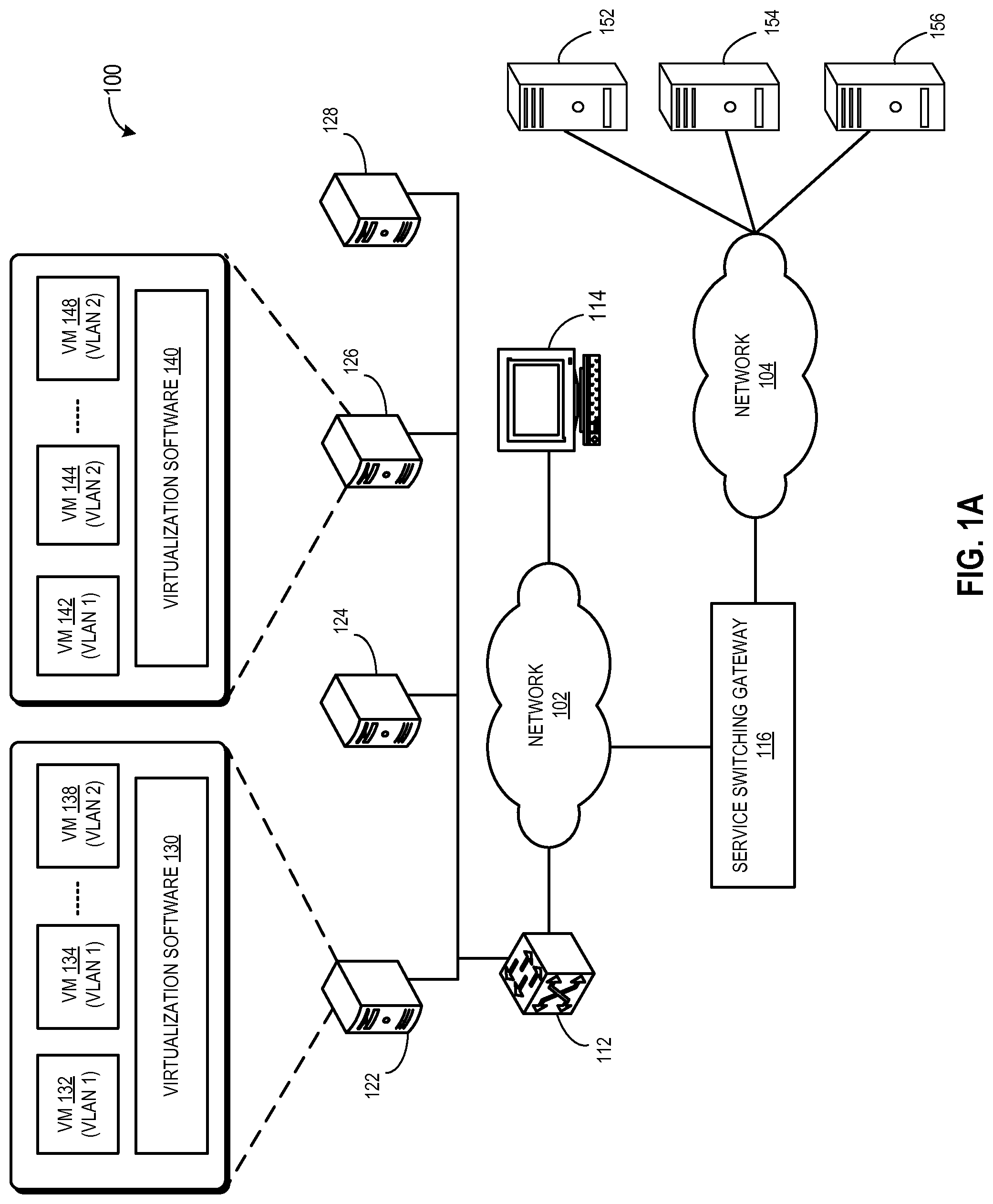
FIG. 1A illustrates an exemplary datacenter environment that facilitates dynamic service switching.
FIG. 1B illustrates encapsulation-based dynamic service switching in conjunction with the example in FIG. 1A.
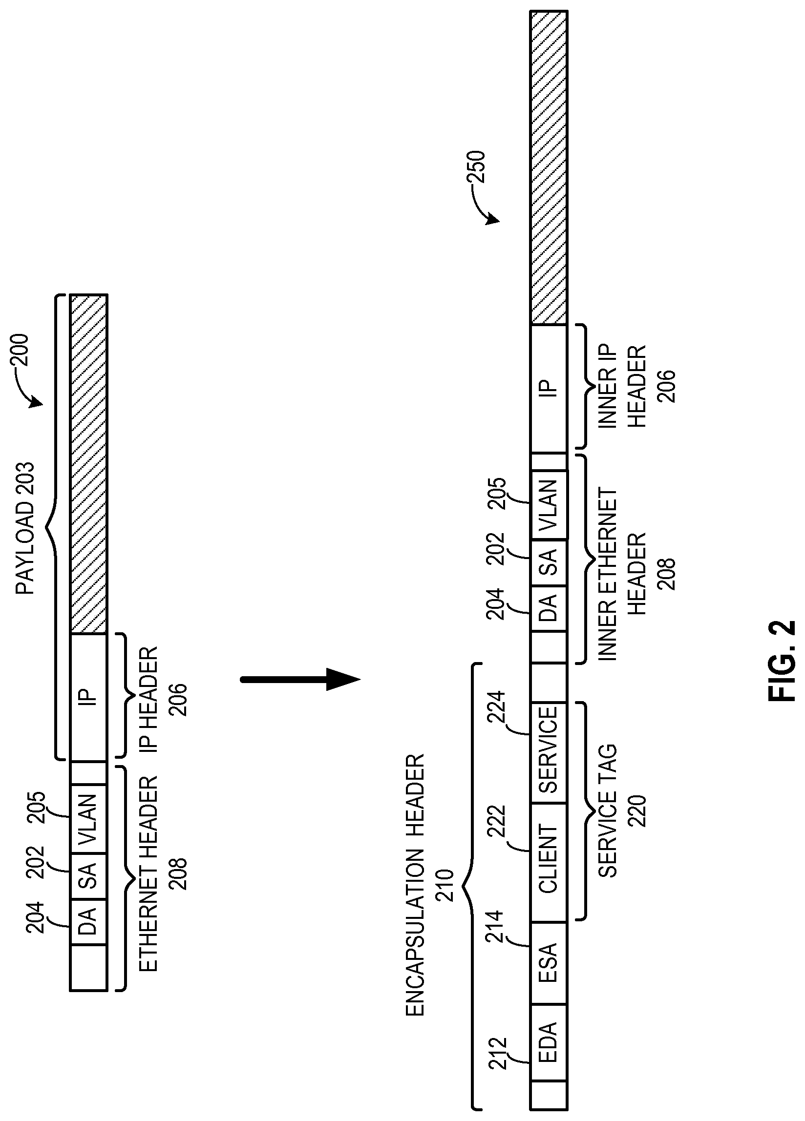
FIG. 2 illustrates header format for a conventional packet and its tunnel encapsulation of dynamic service switching.
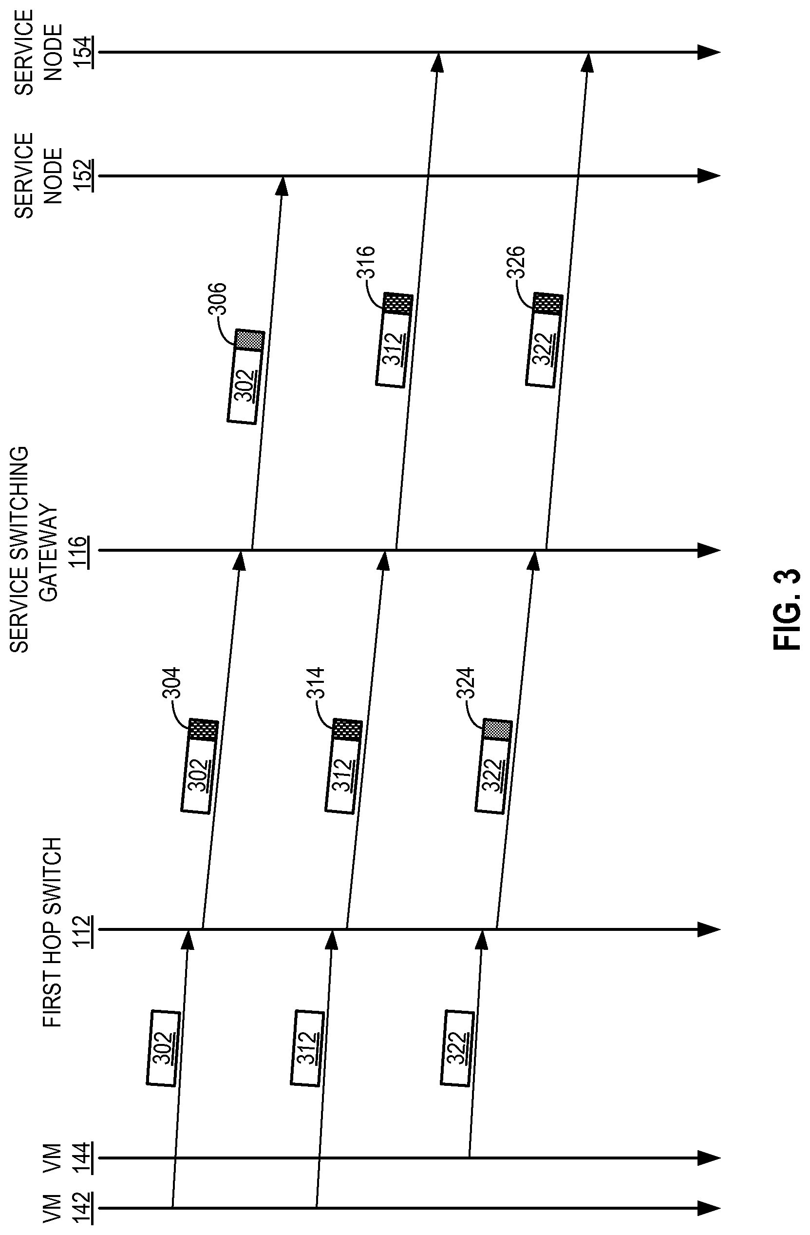
FIG. 3 presents a time-space diagram illustrating an exemplary dynamic service switching process in a datacenter environment.
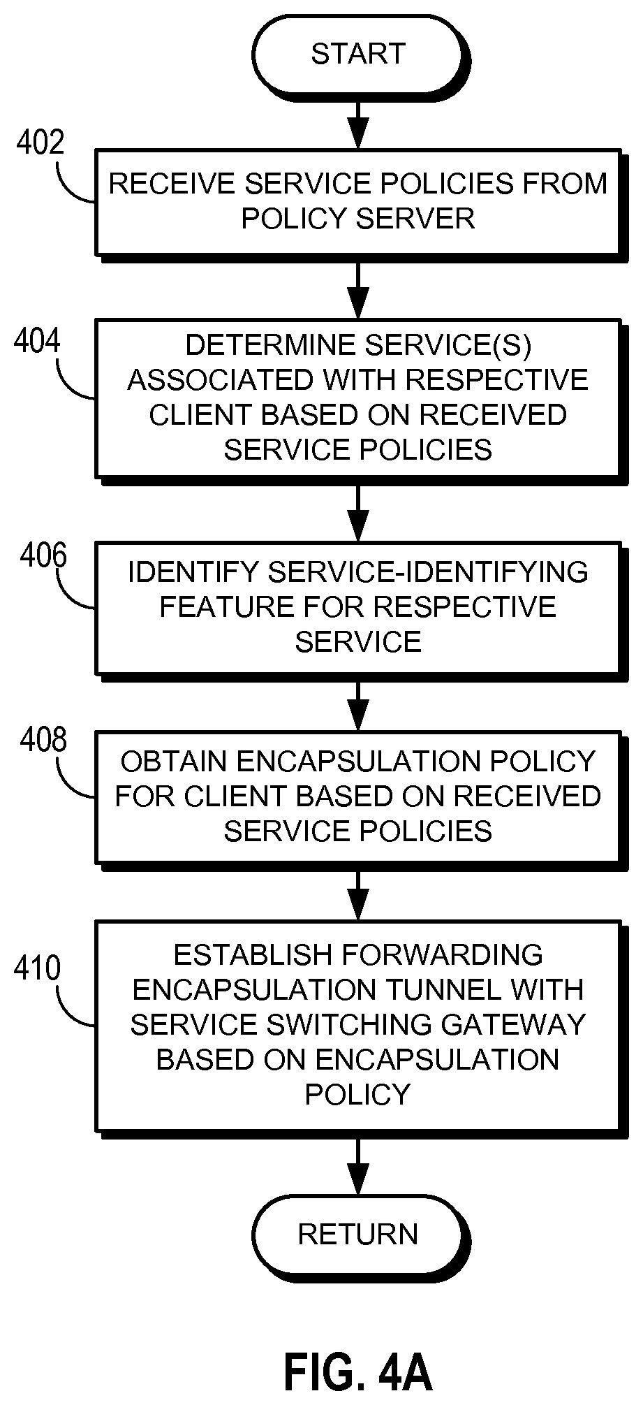
FIG. 4A presents a flow chart illustrating an exemplary process of an origination switch configuring forwarding policies in a datacenter environment based on service requirements.
FIG. 4B presents a flow chart illustrating an exemplary process of an origination switch forwarding a packet in a datacenter environment.
FIG. 5A presents a flow chart illustrating an exemplary process of a service switching gateway configuring service switching policies in a datacenter environment.
FIG. 5B presents a flow chart illustrating an exemplary process of a service switching gateway forwarding a packet in a datacenter environment based on service requirements.
FIG. 6 illustrates an exemplary service switching gateway.
In the figures, like reference numerals refer to the same figure elements.
DETAILED DESCRIPTION
The following description is presented to enable any person skilled in the art to make and use the embodiments, and is provided in the context of a particular application and its requirements. Various modifications to the disclosed embodiments will be readily apparent to those skilled in the art, and the general principles defined herein may be applied to other embodiments and applications without departing from the spirit and scope of the present disclosure. Thus, the present invention is not limited to the embodiments shown, but is to be accorded the widest scope consistent with the principles and features disclosed herein.
Embodiments of the system disclosed herein solve the problem of dynamically facilitating services to a packet in a multitenant datacenter environment by attaching a service tag to the packet based on its service requirements and switching the packet using the service tag. Because of multi-tenancy, the same network infrastructure of the datacenter environment is used to forward traffic flow belonging to different clients. With existing technologies, standard network protocol stack (e.g., layer-2 and layer-3 of the stack) is typically used by a client in a multi-tenant datacenter environment. For example, the client typically uses its own virtual local area network (VLAN) and Internet Protocol (IP) sub-network (subnet) corresponding to a specific range of IP addresses. As a result, the network protocol stack may not be available for associating virtual machines of different clients with different service requirements. Because different services can be provided from different service portals within or outside of the datacenter, the network infrastructure of the datacenter is burdened with selecting the appropriate service portal. Managing individual devices in the network infrastructure to accommodate such diverse service provisioning can be tedious and error-prone.
To solve this problem, a respective packet in a datacenter environment is associated with a service tag which indicates the source client of the packet and/or the service the packet requires. The client to which the originating virtual machine of the packet belongs is the source client of the packet. In some embodiments, upon receiving the packet, a switch, which can be the first-hop switch, determines the source client, and the requested service and creates the service tag. The switch then encapsulates the packet, includes the service tag as a part of the encapsulation, and sends the encapsulated packet to a service switching gateway. Because this switch originates the service switching in the datacenter environment, the switch can be referred to as the origination switch. The service switching gateway uses the service tag to identify service portal capable of providing the requested service to the packet. In some embodiments, the encapsulation is based on a generic encapsulation mechanism. Upon receiving the packet and the service tag, the service switching gateway decapsulates the packet, identifies the source client and the requested service from the service tag, and forwards the packet to a service portal based on the determination. In some embodiments, the service switching gateway can use a generic encapsulation mechanism to forward the packet to a service portal.
FIG. 1A illustrates an exemplary datacenter environment that facilitates dynamic service switching. Datacenter environment 100 includes a number of host machines 122, 124, 126, and 128. A respective host machine can host a plurality of virtual machines running on virtualization software. For example, host machine 122 and 126 run virtualization software 130 and 140, respectively. A number of virtual machines 132, 134, and 138 run on virtualization software 130, and a number of virtual machines 142, 144, and 148 run on virtualization software 140. In this example, virtual machines 132, 134, and 142 belong to VLAN 1, which is associated with one customer, and virtual machines 138, 144, and 148 belong to VLAN 2, which is associated with another customer.
Datacenter environment 100 also includes a policy server 114, which allows a network administrator to provide service policies regarding different clients and the requested services for different traffic flow type from a respective client. Policy server 114 sends these service policies to an origination switch 112 and a service switching gateway 116 via network 102. In this example, originating switch 112 operates as the origination point of service switching in datacenter environment 100. Note that virtualization software 130 and 140, and/or any networking device in network 102 can operate as an origination point of service switching in datacenter environment 100. Service switching gateway 116 is coupled to service portals 152, 154, and 156 via network 104.
Networks 102 and 104 can be local or wide area networks comprising layer-2 (e.g., Ethernet), layer-3 (e.g., IP), and/or any other networking layers. In some embodiments, networks 102 and 104 are parts of the same network (e.g., same local or wide area network). Based on the service policies received from policy server 114, switch 112 configures forwarding policies by determining which traffic flow type (e.g., web, mail, file transfer, etc) from a client requires which service. Similarly, based on the service policies, service switching gateway 116 configures service switching policies by determining which service portal should the traffic flow be directed to.
During operation, virtual machine 132 generates a packet. The term "packet" refers to a group of bits that can be transported together across a network. "Packet" should not be interpreted as limiting embodiments of the present invention to any specific networking layer. "Packet" can be replaced by other terminologies referring to a group of bits, such as "frame," "message," "cell," or "datagram." Switch 112 receives the packet and determines the source client (i.e., the client to which virtual machine 132 belong) of the packet. Switch 112 can detect the source client based on membership to VLAN 1, an associated subnet and a corresponding IP address range, a source (physical or virtual) port, or any point of attachment between virtual machine 132 and switch 112. Switch 112 also detects the traffic flow type of the packet. Switch 112 can inspect headers of one or more layers (e.g., Ethernet and IP) to determine the traffic flow type. For example, if the packet includes a destination Transmission Control Protocol (TCP) port 80, the packet can be considered as part of a web traffic flow.
Based on the identified source client and the traffic flow type, switch 112 determines the requested service for the packet. Not all clients may require all services. For example, one client may require a web filtering service for all packets while another client may not require any web filtering service. If the packet from virtual machine 132 requires any service, switch 112 creates a service tag, which indicates the source client, the requested service for the packet, or both. Switch 112 then attaches the service tag with the packet and sends the packet to service switching gateway 116 via one or more hops through network 102. In some embodiments, switch 112 encapsulates the packet using a generic encapsulation mechanism and attaches the service tag as a part of the encapsulation. Examples of packet encapsulation include, but are not limited to, Generic Routing Encapsulation (GRE) tunneling, Internet Protocol Security (IPsec) tunneling, VLAN encapsulation, and IP encapsulation. Examples of corresponding service tag include, but are not limited to, a GRE key, Security Parameter Index (SPI), VLAN tag, and IP header options. If the packet does not require any service, switch 112 forwards the packet based on the destination information in the header of the packet.
Service switching gateway 116 terminates packet encapsulation from switch 112. Because the networking devices in network 102 forwards the packet based on the encapsulation, these devices do not need any modification to assist service switching. Upon receiving the packet and the service tag, service switching gateway 116 extracts the service tag and identifies the source client, the requested service, or both from the service tag. Suppose that service portal 152 can provide the requested service to the packet. Based on the identification, service switching gateway 116 selects service portal 152 for providing the service to the packet. Service switching gateway 116 then sends the packet to service portal 152 via one or more hops through network 104. In some embodiments, service switching gateway 116 encapsulates the packet based on a generic encapsulation mechanism supported by both service switching gateway 116 and service portal 152. After providing the service, service portal 152 can either forward the packet based on the destination information of the packet or send the packet back to service switching gateway 116. Upon receiving the packet back, service switching gateway 116 attaches the tag back to the packet and sends the packet back to switch 112.
Note that service switching gateway 116 can have packet encapsulation with switch 112 and service 152 using different encapsulation mechanisms. Service switching gateway 116 uses the service tag in the tunnel encapsulation to switch/steer the packet to corresponding service portal 152. FIG. 1B illustrates encapsulation-based dynamic service switching in conjunction with the example in FIG. 1A. In the example in FIG. 1B, during operation, switch 112 receives packets from virtual machines 142 and 144, which belong to different clients (denoted by different VLANs). Switch 112 establishes one or more forwarding encapsulation tunnels 160 with service switching gateway 116 for forwarding packets from virtual machines 142 and 144. An encapsulation tunnel encapsulates a packet between the origination and termination points of the tunnel.
In some embodiments, based on the customer requirements, service policies specify whether to use the same tunnel for multiple clients or use different tunnels for different clients. Consequently, switch 112 and service switching gateway 116 can have different tunnels for different clients based on the service policies. For example, switch 112 forwards packets from virtual machine 142 via tunnel 162 while forwards packets from virtual machine 144 via tunnel 164. Tunnel 162 and 164 can be based on different encapsulation mechanisms, wherein the service tag formats for tunnel 162 and 164 correspond to the respective encapsulation mechanism. For example, if tunnel 162 is an IPSec tunnel while tunnel 164 is a GRE tunnel, the service tags for all packets forwarded via tunnel 162 are IPSec SPIs and for all packets forwarded via tunnel 164 are GRE keys.
On the other hand, service switching gateway 116 establishes one or more service encapsulation tunnels 170 with service portals 152, 154, and 156 for forwarding packets based on their service requirements. In some embodiments, based on the encapsulation mechanisms supported by a respective service portal, service policies specify which encapsulation mechanism to use for establishing an encapsulation tunnel with a service portal. Service switching gateway 116 and service portals 152, 154, and 156 have tunnels 172, 174, and 176, respectively, between them. Tunnels 172, 174, and 176 can be based on different encapsulation mechanism. For example, tunnel 172 can be a GRE tunnel while tunnels 174 and 176 can be IPSec tunnels.
During operation, switch 112 receives a packet, which requires a service from service portal 152, from virtual machine 142. Switch 112 creates a service tag, which is an IPSec SPI, specifying the source client to which virtual machine 142 belongs. The service tag can also include a requested service, which is the service provided by service portal 152. Switch 112 then encapsulates the packet in IPSec tunneling format, includes the generated IPSec SPI in the encapsulation, and forwards the encapsulated packet to service switching gateway 116 via tunnel 162. Intermediate networking devices in network 102 forwards the packet based on the encapsulation. Upon receiving the encapsulated packet, service switching gateway 116 decapsulates the packet, extracts the IPSec SPI (i.e., the service tag), and identifies the source client and/or the requested service.
In some embodiments, service switching gateway 116 maintains a service mapping between the requested service and/or the source client, and the associated service portal 152. Based on the service mapping, identified the source client, and/or requested service, service switching gateway 116 determines service portal 152 as the service destination. Service switching gateway 116 then encapsulates the packet in GRE tunneling format and forwards the encapsulated packet to service portal 152 via tunnel 172. Upon receiving the encapsulated packet, service portal 152 decapsulates the packet and provides the requested service to the packet. In some embodiments, service switching gateway 116 specifies the requested service by regenerating the service tag as a GRE key and incorporates the GRE key in the packet encapsulation. Upon receiving the packet, service portal 152 extracts the service tag and identifies the requested service for the packet. This can be useful when service portal 152 can provide multiple services.
FIG. 2 illustrates header format for a conventional packet and its tunnel encapsulation of dynamic service switching. In this example, a conventional Ethernet packet 200 typically includes a payload 203 and an Ethernet header 208. Typically, payload 203 can include an IP packet which includes an IP header 206. Ethernet header 208 includes a media access control (MAC) destination address (DA) 204, a MAC source address (SA) 202, and optionally a VLAN tag 205.
In one embodiment, switch 112 can encapsulate conventional packet 200 into an encapsulated packet 250. Encapsulated packet 250 typically includes an encapsulation header 210, which corresponds to the encapsulation mechanism. Encapsulation header 210 contains an encapsulation DA 212 and an encapsulation SA 214. The encapsulated packet is forwarded via network 102 based on encapsulation DA 212. Encapsulation header 210 also includes a service tag 220, which indicates the source client 222, a requested service 224 for packet 200, or both. For example, if encapsulation header 210 corresponds to an IPSec tunnel, a GRE tunnel, or a VLAN encapsulation, service tag 220 is an IPSec SPI, a GRE key, or a VLAN tag, respectively.
Take, for example, packet 200 is a web request to a web server generated by virtual machine 142. Typically, an upper layer application in virtual machine 142 generates an IP packet destined for the web server, using web server's IP address. This IP packet becomes payload 203, and the web server's IP address becomes the destination IP address in IP header 206. In addition, virtualization software 140's IP address becomes the source IP address in IP header 206. The layer-2 in virtual machine 142 then generates Ethernet header 208 to encapsulate payload 203. MAC DA 204 of Ethernet header 208 is assigned the default gateway router's MAC address. For example, if switch 112 is the gateway router, MAC DA 204 of Ethernet header 208 is switch 112's MAC address. MAC SA 202 of Ethernet header 208 is virtual machine 142's MAC address. Virtual machine 142 then sends Ethernet packet 200 to switch 112.
When switch 112 receives Ethernet packet 200 from virtual machine 142, switch 112 inspects the Ethernet MAC DA 204, MAC SA 202, VLAN tag 205, and optionally IP header 206 and its payload (e.g., the layer-4 header). Based on this information, switch 112 determines that Ethernet packet 200 is associated with web service and requires a service from service portal 152. Subsequently, switch 112 assembles the encapsulation header 210, attaches service tag 220 (corresponding to an encapsulation mechanism), and forwards packet 220 to service switching gateway 116. Upon receiving packet 220, service switching gateway 116 removes encapsulation header 210 and extracts service tag 220. Service switching gateway 116 then assembles another encapsulation header for the packet and forwards the encapsulated packet to service portal 152.
As mentioned above, when virtual machine 142 sends a packet to the web server, the packet is switched to a service portal. FIG. 3 presents a time-space diagram illustrating an exemplary dynamic service switching process in a datacenter environment. During operation, switch 112 receives packet 302, which requires a service from service portal 152, from virtual machine 142. Switch 112 creates a service tag specifying the source client to which virtual machine 142 belongs and a requested service, which is the service provided by service portal 152. Switch 112 then encapsulates packet 302 in encapsulation header 304, includes the generated service tag in encapsulation header 304, and forwards encapsulated packet 302 to service switching gateway 116. Upon receiving encapsulated packet 302, service switching gateway 116 decapsulates packet 302, extracts the service tag from encapsulation header 304, and identifies the source client and/or the requested service. Based on the identified the source client and/or the requested service, service switching gateway 116 determines service portal 152 as the service destination. Service switching gateway 116 then encapsulates packet 302 in another encapsulation header 306 and forwards encapsulated packet 302 to service portal 152. Note that encapsulation headers 304 and 306 can be based on different encapsulation mechanism.
Switch 112 can receive another packet 312, which requires a service from service portal 154, from virtual machine 142. Switch 112 encapsulates packet 312 in encapsulation header 314, includes a corresponding service tag in encapsulation header 314, and forwards encapsulated packet 312 to service switching gateway 116. However, based on the service policies associated with a client, switch 112 can use a different encapsulation mechanism for that client. In this example, when switch 112 receives packet 322, which requires a service from service portal 154, from virtual machine 144 belonging to a different client, switch 112 encapsulates packet 322 in encapsulation header 324, which is based on a different encapsulation mechanism than encapsulation headers 304 and 314. Switch 112 then includes a corresponding service tag in encapsulation header 324, and forwards encapsulated packet 322 to service switching gateway 116.
Upon receiving encapsulated packets 312 and 322, service switching gateway 116 decapsulates packets 312 and 322, extracts the service tag from encapsulation headers 314 and 324, respectively, and identifies the source client and/or the requested service. Based on the identified the source client and/or the requested service and a service mapping, service switching gateway 116 determines service portal 154 as the service destination. Service switching gateway 116 then encapsulates packets 312 and 322 in encapsulation headers 316 and 326, respectively, and forwards encapsulated packets 312 and 322 to service portal 154. Encapsulation headers 304 and 306 can be based on the same encapsulation mechanism even though they are generated at different locations.
FIG. 4A presents a flow chart illustrating an exemplary process of an origination switch configuring forwarding policies in a datacenter environment based on service requirements. During operation, the switch receives service policies from a policy server (operation 402), as described in conjunction with FIG. 1A. The switch then determines the service(s) associated with a respective client based on the received service policies (operation 404). The switch also identifies service-identifying features of a respective service (operation 406). For example, service-identifying feature of web filtering can be determining whether a packet includes a destination TCP port 80. The switch obtains encapsulation policy for a respective client based on the received service policies (operation 408). An encapsulation policy dictates the supported encapsulation mechanisms, and which mechanism should be used under which circumstance
References
D00000
D00001
D00002
D00003
D00004
D00005
D00006
D00007
D00008
D00009
XML
uspto.report is an independent third-party trademark research tool that is not affiliated, endorsed, or sponsored by the United States Patent and Trademark Office (USPTO) or any other governmental organization. The information provided by uspto.report is based on publicly available data at the time of writing and is intended for informational purposes only.
While we strive to provide accurate and up-to-date information, we do not guarantee the accuracy, completeness, reliability, or suitability of the information displayed on this site. The use of this site is at your own risk. Any reliance you place on such information is therefore strictly at your own risk.
All official trademark data, including owner information, should be verified by visiting the official USPTO website at www.uspto.gov. This site is not intended to replace professional legal advice and should not be used as a substitute for consulting with a legal professional who is knowledgeable about trademark law.