Mirror having an integrated electronic display
Dunn , et al.
U.S. patent number 10,692,407 [Application Number 15/636,813] was granted by the patent office on 2020-06-23 for mirror having an integrated electronic display. This patent grant is currently assigned to Manufacturing Resources International, Inc.. The grantee listed for this patent is Manufacturing Resources International, Inc.. Invention is credited to William Dunn, Michael LeCave.


| United States Patent | 10,692,407 |
| Dunn , et al. | June 23, 2020 |
Mirror having an integrated electronic display
Abstract
An apparatus for presenting an image on a mirrored display includes an electronic display having backlight and a viewing area. A cover glass has a surface area is positioned in front of and substantially parallel with the electronic display such that the surface area substantially covers the viewing area. A reflective layer located on and substantially coextensive with said cover glass is partially silvered where the reflective layer is located above the viewing area and substantially fully silvered on the remaining surface thereof.
| Inventors: | Dunn; William (Alpharetta, GA), LeCave; Michael (Gainesville, GA) | ||||||||||
|---|---|---|---|---|---|---|---|---|---|---|---|
| Applicant: |
|
||||||||||
| Assignee: | Manufacturing Resources
International, Inc. (Alpharetta, GA) |
||||||||||
| Family ID: | 60911073 | ||||||||||
| Appl. No.: | 15/636,813 | ||||||||||
| Filed: | June 29, 2017 |
Prior Publication Data
| Document Identifier | Publication Date | |
|---|---|---|
| US 20180012526 A1 | Jan 11, 2018 | |
Related U.S. Patent Documents
| Application Number | Filing Date | Patent Number | Issue Date | ||
|---|---|---|---|---|---|
| 62360175 | Jul 8, 2016 | ||||
| Current U.S. Class: | 1/1 |
| Current CPC Class: | G09F 9/33 (20130101); G03B 21/56 (20130101); G09F 13/14 (20130101); G09F 13/08 (20130101); G09F 13/0404 (20130101); G09F 23/00 (20130101); G09F 13/12 (20130101); G09F 13/18 (20130101); G09F 27/005 (20130101); G09F 9/35 (20130101); G09F 2027/001 (20130101) |
| Current International Class: | G09F 13/12 (20060101); G09F 13/18 (20060101); G09F 9/33 (20060101); G09F 13/08 (20060101); G09F 13/04 (20060101); G03B 21/56 (20060101); G09F 13/14 (20060101); G09F 23/00 (20060101) |
References Cited [Referenced By]
U.S. Patent Documents
| 3629972 | December 1971 | Rehberg et al. |
| 4040726 | August 1977 | Paca |
| 4299092 | November 1981 | Ibrahim |
| 4371870 | February 1983 | Biferno |
| 4738042 | April 1988 | Corden et al. |
| 4853678 | August 1989 | Bishop, Jr. et al. |
| 7413233 | August 2008 | Jung |
| 7455412 | November 2008 | Rottcher |
| 7513637 | April 2009 | Kelly et al. |
| 7922381 | April 2011 | Han et al. |
| 8254121 | August 2012 | Lee et al. |
| 8417376 | April 2013 | Smolen |
| 8578081 | November 2013 | Fils |
| 8683745 | April 2014 | Artwohl et al. |
| 8982013 | March 2015 | Sako et al. |
| 8988635 | March 2015 | Dunn et al. |
| 9052536 | June 2015 | Artwohl et al. |
| 9155405 | October 2015 | Artwohl et al. |
| 9173509 | November 2015 | Mischel, Jr. |
| 9500801 | November 2016 | Dunn |
| 9500896 | November 2016 | Dunn et al. |
| 9514661 | December 2016 | Riegel |
| 9519185 | December 2016 | Dunn et al. |
| 9526352 | December 2016 | Dunn et al. |
| 9535293 | January 2017 | Dunn |
| 9633366 | April 2017 | Dunn |
| 9661939 | May 2017 | Dunn et al. |
| 9684124 | June 2017 | Dunn |
| 9733420 | August 2017 | Dunn et al. |
| 10052026 | August 2018 | Tran |
| 2002/0064037 | May 2002 | Lee |
| 2002/0075552 | June 2002 | Poll et al. |
| 2002/0187575 | December 2002 | Maruyama et al. |
| 2003/0117790 | June 2003 | Lee et al. |
| 2004/0160388 | August 2004 | O'Keeffe |
| 2005/0195972 | September 2005 | Barr |
| 2005/0265019 | December 2005 | Sommers et al. |
| 2006/0215958 | September 2006 | Yeo et al. |
| 2006/0284788 | December 2006 | Robinson et al. |
| 2007/0151274 | July 2007 | Roche et al. |
| 2007/0171647 | July 2007 | Artwohl et al. |
| 2007/0195535 | August 2007 | Artwohl et al. |
| 2007/0214812 | September 2007 | Wagner et al. |
| 2007/0288332 | December 2007 | Naito |
| 2008/0024047 | January 2008 | Juo et al. |
| 2008/0055534 | March 2008 | Kawano |
| 2008/0094854 | April 2008 | Coleman et al. |
| 2008/0284942 | November 2008 | Mahama et al. |
| 2008/0295033 | November 2008 | Lee et al. |
| 2009/0002990 | January 2009 | Becker et al. |
| 2009/0015400 | January 2009 | Breed |
| 2009/0097227 | April 2009 | Kim et al. |
| 2009/0121970 | May 2009 | Ozbek |
| 2009/0225519 | September 2009 | Mischel, Jr. |
| 2009/0278766 | November 2009 | Sako et al. |
| 2009/0298547 | December 2009 | Kim et al. |
| 2009/0300953 | December 2009 | Frisch et al. |
| 2010/0026912 | February 2010 | Ho |
| 2010/0058628 | March 2010 | Reid |
| 2010/0118200 | May 2010 | Gelman et al. |
| 2010/0162747 | July 2010 | Hamel et al. |
| 2010/0189571 | July 2010 | Coonrod |
| 2010/0238394 | September 2010 | Dunn |
| 2010/0293827 | November 2010 | Suss et al. |
| 2010/0309687 | December 2010 | Sampsell et al. |
| 2011/0056102 | March 2011 | Reid |
| 2011/0083460 | April 2011 | Thomas et al. |
| 2011/0116000 | May 2011 | Dunn et al. |
| 2011/0116231 | May 2011 | Dunn et al. |
| 2011/0302944 | December 2011 | Howington et al. |
| 2012/0020560 | January 2012 | Zarubinsky |
| 2012/0062080 | March 2012 | Maslen |
| 2012/0105424 | May 2012 | Lee et al. |
| 2012/0105428 | May 2012 | Fleck et al. |
| 2012/0206500 | August 2012 | Koprowski et al. |
| 2012/0206941 | August 2012 | He |
| 2012/0275477 | November 2012 | Berendt et al. |
| 2012/0287368 | November 2012 | Que et al. |
| 2013/0016296 | January 2013 | Fujita et al. |
| 2013/0063326 | March 2013 | Riegel |
| 2013/0120815 | May 2013 | Aspnes et al. |
| 2013/0151006 | June 2013 | Garson et al. |
| 2013/0158703 | June 2013 | Lin et al. |
| 2013/0208447 | August 2013 | Maslen |
| 2013/0211583 | August 2013 | Borra |
| 2013/0265525 | October 2013 | Dunn et al. |
| 2013/0271696 | October 2013 | Dunn |
| 2014/0062316 | March 2014 | Tischler et al. |
| 2014/0078407 | March 2014 | Green et al. |
| 2014/0085564 | March 2014 | Hendren et al. |
| 2014/0104538 | April 2014 | Park et al. |
| 2014/0137065 | May 2014 | Feng et al. |
| 2014/0144083 | May 2014 | Artwohl et al. |
| 2014/0204452 | July 2014 | Branson |
| 2014/0285732 | September 2014 | Tanabe et al. |
| 2014/0300979 | October 2014 | Tomida |
| 2014/0320950 | October 2014 | Saxe et al. |
| 2014/0333541 | November 2014 | Lee et al. |
| 2015/0035432 | February 2015 | Kendall et al. |
| 2015/0177480 | June 2015 | Bullock et al. |
| 2015/0250021 | September 2015 | Stice et al. |
| 2015/0253612 | September 2015 | Hasegawa et al. |
| 2015/0300628 | October 2015 | Dunn et al. |
| 2015/0309263 | October 2015 | Abovitz et al. |
| 2015/0338715 | November 2015 | Schaefer et al. |
| 2015/0362667 | December 2015 | Dunn |
| 2015/0362768 | December 2015 | Dunn |
| 2015/0362792 | December 2015 | Dunn et al. |
| 2015/0363819 | December 2015 | Dunn |
| 2015/0366083 | December 2015 | Dunn et al. |
| 2016/0037657 | February 2016 | Yoshizumi |
| 2016/0061514 | March 2016 | Seo et al. |
| 2016/0091755 | March 2016 | Dunn |
| 2016/0095450 | April 2016 | Trulaske, Sr. |
| 2016/0103275 | April 2016 | Diaz et al. |
| 2016/0106231 | April 2016 | Dunn et al. |
| 2016/0192451 | June 2016 | Dunn et al. |
| 2017/0046991 | February 2017 | Riegel |
| 2017/0053456 | February 2017 | Cho |
| 2017/0068042 | March 2017 | Dunn et al. |
| 2017/0068044 | March 2017 | Dunn |
| 2017/0099960 | April 2017 | Dunn et al. |
| 2017/0108735 | April 2017 | Dunn |
| 2017/0228770 | August 2017 | Dunn |
| 2017/0256115 | September 2017 | Diaz |
| 2815355 | May 2012 | CA | |||
| 101949526 | Jan 2011 | CN | |||
| 202815379 | Mar 2013 | CN | |||
| 3023975 | May 2016 | EP | |||
| 3155607 | Apr 2017 | EP | |||
| 2232520 | Dec 1990 | GB | |||
| 2005-224267 | Aug 2005 | JP | |||
| 2006-126379 | May 2006 | JP | |||
| 3158578 | Apr 2010 | JP | |||
| 2010171010 | Aug 2010 | JP | |||
| 2010-273935 | Dec 2010 | JP | |||
| 5173088 | Mar 2013 | JP | |||
| 2015-231454 | Dec 2015 | JP | |||
| 1020040045939 | Jun 2004 | KR | |||
| 10-2011-0040909 | Apr 2011 | KR | |||
| 20120044874 | May 2012 | KR | |||
| 10-2012-0081330 | Jul 2012 | KR | |||
| 10-2013-0003384 | Jan 2013 | KR | |||
| 10-2015-0128134 | Nov 2015 | KR | |||
| WO2006055873 | May 2006 | WO | |||
| WO2010116202 | Oct 2010 | WO | |||
| WO2013056109 | Apr 2013 | WO | |||
| WO2015195681 | Dec 2015 | WO | |||
| WO2017151934 | Sep 2017 | WO | |||
Other References
|
A Vogler & H. Kunkley, Photochemistry and Beer, Jan. 1982, 3 Pages, vol. 59, No. 1. cited by applicant . Dave Ross, How Transmissive Film Works, 2008, 9 Pages. cited by applicant . Pilkington Tec Glass, For the Refrigeration Market, 2002, 2 Pages. cited by applicant. |
Primary Examiner: Davis; Cassandra
Attorney, Agent or Firm: Standley Law Group LLP Standley; Jeffrey S. Smith; Adam J.
Parent Case Text
CROSS REFERENCE TO RELATED APPLICATIONS
This application claims the benefit of U.S. Provisional Patent Application No. 62/360,175 filed Jul. 8, 2016, the disclosure of which is hereby incorporated by reference in its entirety.
Claims
What is claimed is:
1. An apparatus for presenting an image on a mirrored display comprising: an electronic display assembly having a viewing area and comprising a backlight; a cover glass having a surface area, wherein said cover glass is positioned in front of and parallel with the electronic display assembly such that the surface area covers the viewing area; a reflective layer positioned on and coextensive with said cover glass, wherein said reflective layer is partially silvered where the reflective layer is located above the viewing area and is fully silvered on the remaining surface thereof; a sensor configured to detect the presence of a person in front of said mirrored display; a processor electrically connected with said sensor and said electronic display assembly, wherein said processor is configured to alter the image displayed on the electronic display assembly if the sensor detects the presence of a person in front of said mirrored display; and said processor is configured to alter the image displayed on the electronic display assembly by operating said electronic display assembly in a lower power mode until the sensor detects the presence of the person and then operating the electronic display assembly in a normal power mode.
2. The apparatus of claim 1 wherein: said electronic display comprises a liquid crystal stack.
3. The apparatus of claim 1 further comprising: a housing surrounding at least the back, sides, top, and bottom of said electronic display, said cover glass, and said reflective layer.
4. The apparatus of claim 1 wherein: said reflective layer is half slivered where the reflective layer is located above the viewing area.
5. The apparatus of claim 1 further comprising: a touch screen layer positioned in front of and parallel with said viewing area, wherein said touch screen layer is configured to receive touch input from a person; and a processor electrically connected with said touch screen layer and configured to alter the image displayed on the electronic display assembly based upon the received touched input.
6. The apparatus of claim 1 further comprising: a timing and control board electrically connected with said electronic display assembly; and a video player electrically connected with said processor.
7. The apparatus of claim 1 further comprising: a network interface controller electrically connected with said electronic display assembly.
8. The apparatus of claim 1 further comprising: a first optical film positioned below, parallel to, and coextensive with said cover glass; and a second optical film positioned below, parallel to, and coextensive with said first optical layer.
9. The apparatus of claim 1 wherein: the surface area is at least twice the size of the viewing area.
10. The apparatus of claim 1 further comprising: an opaque layer located below the fully silvered portions of the reflective layer.
11. The system of claim 1 wherein: the lower power mode comprises a non-zero power level.
12. A system for presenting an image on a mirrored display comprising: an electronic display having a viewing area; a transparent cover having a surface area and positioned in front of and parallel with the electronic display assembly such that the surface area covers the viewing area; a reflective layer positioned parallel to and coextensive with said transparent panel, wherein said reflective layer is partially silvered where the reflective layer is located above the viewing area and fully silvered on the remainder thereof; a timing and control board electrically connected to said electronic display; a video player electrically connected to said timing and control board; a sensor positioned and configured to detect the presence of a person at the mirrored display; a touch screen located between said reflective layer and said electronic display, wherein said touch screen is coextensive with at least a portion of said electronic display; and a processor in electrical connection with said video player and said sensor, wherein said processor is configured to alter the image if the sensor detects the presence of the person by increasing the power supplied to the electronic display, and wherein said processor is configured to alter the image based upon user input received at the touch screen.
13. The system of claim 12 wherein: the processor is configured to increase the power supplied to the electronic display from a non-zero power level to a higher, non-zero power level.
14. A method for presenting an image on a mirrored display comprising the steps of: providing an electronic display located behind and parallel with a transparent panel and a reflective layer, wherein said reflective layer is located on and is coextensive with the transparent panel and said reflective layer is partially silvered where said reflective layer is located above the electronic display and at fully silvered over the remainder thereof, a touch screen layer located above and coextensive with said electronic display, and a sensor configured to detect the presence of a person near the mirrored display; displaying the image on the electronic display, wherein the image displayed is an article of clothing; monitoring for the presence of a person near the mirrored display; operating the electronic display in a low power mode when a person is not detected; operating the electronic display in a normal mode when a person is detected; detecting touch input from a person; and adjusting the image in response to the touch input, wherein the image is changed to a different article of clothing in response to the touch input.
15. The method of claim 14 further comprising the steps of: providing a network interface controller; receiving instructions regarding the image via the network interface controller; and adjusting the image based upon the instructions received.
16. The method of claim 14 wherein: the low power mode comprises a non-zero power level.
Description
TECHNICAL FIELD
Embodiments of the present invention generally relate to electronic displays.
BACKGROUND AND SUMMARY OF THE INVENTIVE CONCEPT
Mirrors are used for utilitarian and decorative purposes and are often placed in retail locations for both purposes. For example, mirrors are placed in dressing rooms or near retail items so that a person may view the fit and look of the product on themselves before purchasing. Two way mirrors (sometimes also referred to as one way mirrors) present a semi-transparent view from one side of the mirror and a semi-reflective view from the other side of the mirror. These mirrors are used by police in interrogation rooms, for example, so that the investigators or witnesses may observe the person being interrogated but the person being interrogated cannot view the observers. These mirrors are also used, for example, by stores to mask the direction of a security camera lens, as well as many other applications.
Advertising displays have long been used in retail locations to promote various products and services. These advertising displays may be static posters or images displayed on electronic displays.
Exemplary embodiments of the mirrored display relate to an optical stack having an intergrated electronic display. The optical stack may be a two way mirror with the electronic display mounted therebehind such that the image displayed on the electronic display can be shown through the optical stack when the electronic display is illuminated. When the electronic display is not illuminated, the optical stack may appear as a reflective surface. The mirrored display may also comprise a video player, a timing and control board, and other components that are electrically connected to the electronic display and configured control static or video images displayed on the electronic display.
In other exemplary embodiments, the electronic display may be a capacitive touch screen display. The mirrored display may further comprise a processor that receives a user's input and updates the displayed image based on the user's input. For example and not to serve as a limitation, the user may select various clothing items for display on the mirrored display such that the user can see a visual depiction of the clothing item on the user without having to actually wear the clothing item. The mirrored display may include a sensor that detects when a person is in view of the mirrored display and operate the electronic display accordingly.
BRIEF DESCRIPTION OF THE DRAWINGS
In addition to the features mentioned above, other aspects of the present invention will be readily apparent from the following descriptions of the drawings and exemplary embodiments, wherein like reference numerals across the several views refer to identical or equivalent features, and wherein:
FIG. 1 is a simplified block diagram of an exemplary embodiment of the mirrored display also indicating section line A-A;
FIG. 2 is a detailed sectional view taken along section line A-A of FIG. 1;
FIG. 3 is a simplified block diagram of another exemplary embodiment of the mirrored display also indicating section lines B-B and C-C;
FIG. 4 is a detailed sectional view taken along section line B-B of FIG. 3;
FIG. 5 is a detailed sectional view taken along section line C-C of FIG. 3; and
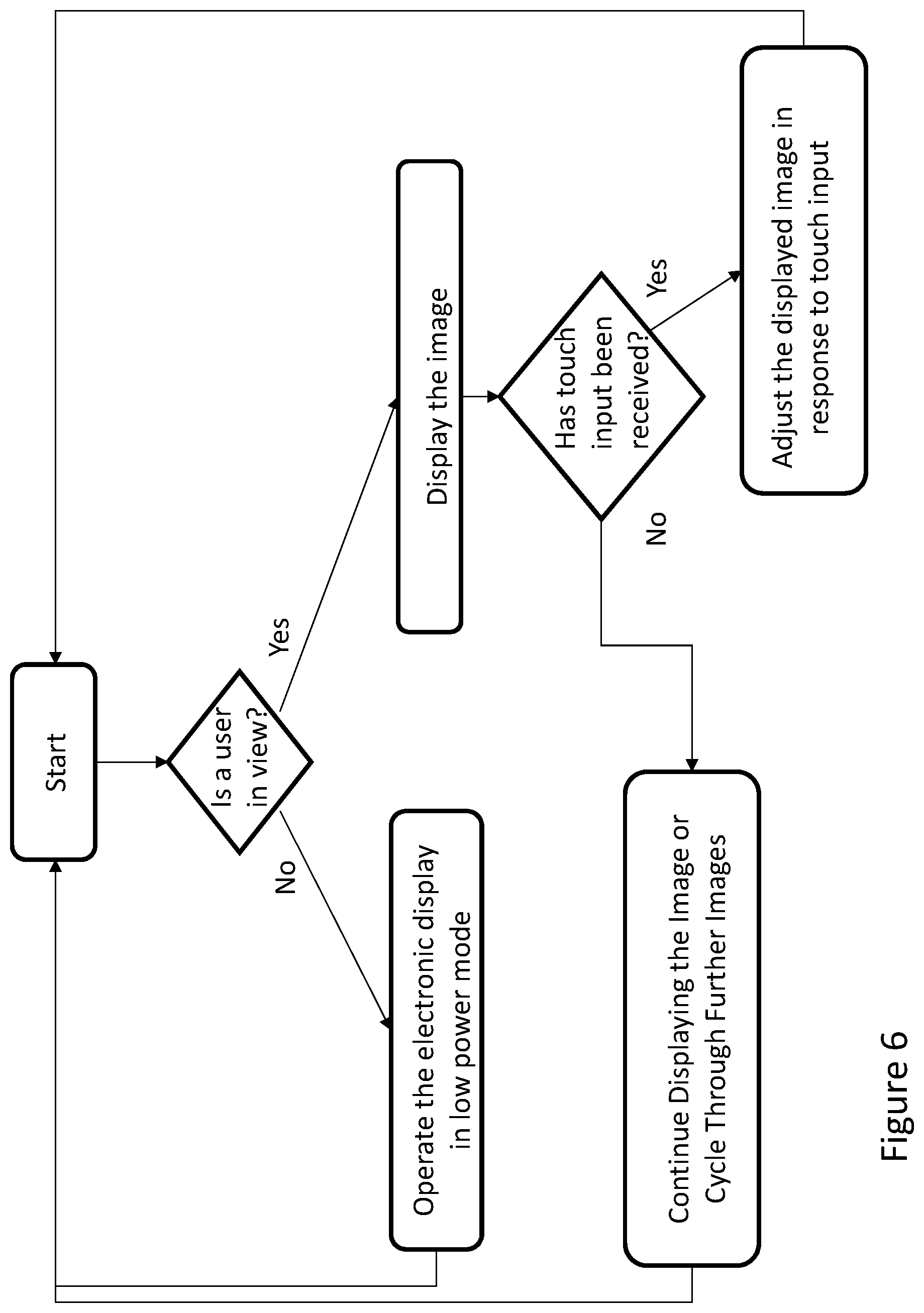
FIG. 6 is an exemplary logical flowchart for operating the mirrored display of either FIG. 1 or FIG. 3.
DETAILED DESCRIPTION OF EXEMPLARY EMBODIMENT(S)
The invention is described more fully hereinafter with reference to the accompanying drawings, in which exemplary embodiments of the invention are shown. This invention may, however, be embodied in many different forms and should not be construed as limited to the exemplary embodiments set forth herein. Rather, these embodiments are provided so that this disclosure will be thorough and complete, and will fully convey the scope of the invention to those skilled in the art. In the drawings, the size and relative sizes of layers and regions may be exaggerated for clarity.
The terminology used herein is for the purpose of describing particular embodiments only and is not intended to be limiting of the invention. As used herein, the singular forms "a", "an" and "the" are intended to include the plural forms as well, unless the context clearly indicates otherwise. It will be further understood that the terms "comprises" and/or "comprising," when used in this specification, specify the presence of stated features, integers, steps, operations, elements, and/or components, but do not preclude the presence or addition of one or more other features, integers, steps, operations, elements, components, and/or groups thereof.
Embodiments of the invention are described herein with reference to illustrations that are schematic illustrations of idealized embodiments (and intermediate structures) of the invention. As such, variations from the shapes of the illustrations as a result, for example, of manufacturing techniques and/or tolerances, are to be expected. Thus, embodiments of the invention should not be construed as limited to the particular shapes of regions illustrated herein but are to include deviations in shapes that result, for example, from manufacturing.
Unless otherwise defined, all terms (including technical and scientific terms) used herein have the same meaning as commonly understood by one of ordinary skill in the art to which this invention belongs. It will be further understood that terms, such as those defined in commonly used dictionaries, should be interpreted as having a meaning that is consistent with their meaning in the context of the relevant art and will not be interpreted in an idealized or overly formal sense unless expressly so defined herein.
It is well known that electronic display such as the ones described herein are capable of displaying static images as well as video. As used herein, the terms are interchangeable, since the functionality of the device is the same as it relates to the exemplary embodiments.
FIG. 1 In an exemplary embodiment the mirrored display 100 comprises an optical stack 102 and an electronic display 104. The mirrored display 100 may comprise a cabinet or housing that frames and secures the optical stack 102 such that the reflective surface faces a user/viewer, the cabinet may also secure other components of the mirrored display 100. The mirrored display 100 and the optical stack 102 may be any size and shape relative to one another. The optical stack 102 may contain one or more reflective materials such as, but not limited to, silver, tin, nickel, mercury, aluminum, aluminum oxides, gold, chrome, silicon oxides, silicon nitrides, some combination thereof, or the like. The partially silver or half silvered mirror may also be accomplished by organizing the die-electric optical coating components in such an order to result non-conductive "silvered" appearing mirror.
The optical stack 102 may be a two-way (aka and hereinafter also one-way) mirror design. To accomplish the two-way mirror design, the optical stack 102 may be partially silvered. In exemplary embodiments, the optical stack 102 may be substantially half silvered. In this way, when some or all of the electronic display 104 is illuminated, the image displayed thereon may appear through the optical stack 102 and the unilluminated portions of the electronic display 104 and the optical stack 102 may appear as a reflective surface.
The electronic display 104 may be mounted inside the mirrored display 100 behind the optical stack 102. In exemplary embodiments, the electronic display 102 has a smaller surface area than the total surface area of the mirrored display 100, though any size and shape electronic display 104 is contemplated. The electronic display 104 may be any type of electronic display 104 such as, but not limited to, a Liquid Crystal Display (LCD), a Light Emitting Diode (LED), Organic LED (OLED), electroluminescent polymer display, or the like. In exemplary embodiments, only the portion of the optical stack 102 having the electronic display 104 located thereunder may be of the two-way design, while the remaining portions of the optical stack 102 may be of a normal mirrored (i.e., substantially fully silvered) surface. In other exemplary embodiments, the entire optical stack 102 may be of the two-way design.
In exemplary embodiments, the optical stack 102 may comprise a reflective layer 205. The reflective layer 205 may be substantially coextensive with the optical stack 102. The reflective layer 205 may be comprised of reflective materials such that it is partially silvered or half silvered. In exemplary embodiments, the reflective layer 205 is partially silvered where the reflective layer 205 is located above the electronic display 104 or the viewing area and substantially fully silvered on the remaining surface thereof.
The electronic display 104 may be in electrical connection with a timing and control board (TCON) 106 which may be in electrical connection with a video player 108. The TCON 106 and video player 108 may be mounted in the cabinet for the optical stack 102 or may be located remotely. The TCON 106 and video player 108 may control the images displayed on the electronic display 104. For example, and not intended to be limiting, a general advertising image can be displayed anywhere on the electronic display 104. Alternatively, the image of a clothing item may be displayed on the mirrored display 100, and sized/positioned over the reflection of the viewer such that the viewer can see a visual depiction of how the clothing item would fit and appear on their body without having to actually try the clothing item on.
FIG. 2 A detailed sectional view taken along section line A-A of FIG. 1 reveals the various layers that comprise the optical stack 102 and the electronic display 104 of the mirrored display 100. The section line A-A preferably cuts horizontally through the indicated portion of the mirrored display 100. A glass panel 204 may form the outermost layer of the optical stack 102. A first optical film 206 is preferably bonded to the rear surface of the glass panel 204, preferably with index-matching optical adhesive. A second optical film 207 may be bonded to the rear surface of the first optical film 206, again preferably using an index-matched optical adhesive. In an exemplary embodiment, the second optical film 207 may contain an anti-reflective coating on one or both sides. In some alternative embodiments, one or both sides of the first optical film 206 may contain an anti-reflective coating. Additionally, the outermost face of the glass panel 204 may also contain an anti-reflective coating. Preferably, the first optical film 206 may be a zero retardation film such as TAC, or a XENOR zero retardation film, or a linear polarizer. Also preferably, the second optical film 207 would be a linear polarizer. However, in some embodiments, the second optical film 207 would instead be a projective capacitance touch screen, comprising one or two layers of low birefringent or zero retardation films.
The reflective layer 205 may be integrally formed with, positioned on, or located adjacent to the glass panel 204, and may be partially silvered on the portions that are located above the electronic display 104 and substantially full silvered on the portions where the electronic display 104 is not located thereunder. In other exemplary embodiments, the entire optical stack 102 is partially silvered or the reflective layer 205 may be located anywhere in the optical stack 102. The rear surface of the glass panel 204 may be painted black or backed with or otherwise mounted above a fully or partially opaque layer in the locations where the electronic display 104 is not located thereunder. This may improve reflectivity of the optical stack 102.
The electronic display 104 may be located below the optical stack 102 and may be comprised of a series of layers, the specifics being dependent upon the type of electronic display 104 chosen. In an exemplary embodiment, the electronic display 104 comprises a liquid crystal stack with a backlight positioned to illuminate the liquid crystal stack.
FIG. 3 In another exemplary embodiment, a mirrored display 200 may be similar to the mirrored display 100 of FIG. 1 with the addition of several features to increase interactivity and provide other desirable benefits. A sensor 116 may be mounted to the cabinet of the mirrored display 200 or be located behind the two-way portion of the optical stack 102. The sensor 116 may be a motion sensor, proximity sensor, or the like and may be configured to detect if a user/viewer is standing in front of, or in close proximity with, the mirrored display 200. In other exemplary embodiments, the sensor 116 may further comprise an ambient light sensor and may adjust the illumination level of the electronic display 104. Regardless, the sensor 116 may be in electrical connection (wired or wireless) with a processor 112, which may be in electrical connection (wired or wireless) with the video player 108.
In exemplary embodiments the electronic display 104 may include touch screen technology, preferably a capacitive touch screen, and the processor 112 may also be in electrical communication with a plurality of touch inputs 114. The touch inputs 114 may receive the user's input and the processor 112 may determine the location, type, duration, or the like of the user's touch and direct the video player 108 to make appropriate changes to the image being displayed on the electronic display 104.
Additionally, the mirrored display 200 may comprise a network interface controller 110. The network interface controller 110 may be in electrical connection (wired or wireless) with the video player 108 or another component of the mirrored display 200. The network interface controller 110 may connect the mirrored display 200 to a communications network such as an internet, intranet, satellite communications network, cellular network, the world wide web, or the like. In this way, the mirrored display 200 may receive remote updates for the images to be displayed or the operation of the mirrored display 200 generally.
FIG. 4 A detailed sectional view taken along section line B-B of FIG. 3 reveals the various layers that comprise the optical stack 102 and the electronic display 104 of the mirrored display 200. These layers may be the same as those illustrated and described with respect to FIG. 2 with the addition of a touch screen layer 216 located below the glass panel 204. The touch screen layer 216 may comprise a grid of wires and electrodes configured to detect the location of a user's finger or other appendage. The touch screen layer 216 may be electrically connected to the touch inputs 114.
FIG. 5 A detailed sectional view taken along section line C-C of FIG. 3 reveals the internal structure and various layers of the mirrored display 200 in the areas where the electronic display 104 is not located below the optical stack 102. In these areas, only the optical stack 102, comprising of the layers shown and described above, may be present. This may result in a cavernous area where the electronic display 104 would other reside. In exemplary embodiments, various electronic components 220 such as, but not limited to, power supplies, cooling or thermal management systems, the processor 112, TCON 106, video player 108, and network interface controller 110 could be secured in this area, though such is not required. In other embodiments, the various electronic components 220 could be positioned above or below the optical stack 102, rather than behind it as shown in this Figure.
FIG. 6 The mirrored display 200 may be in communication with the sensor 116 such that it detects whether the user/viewer is in view of the mirrored display 200. If the user is not in view, the mirrored display 200 may be driven in a low power mode (little or no luminance produced by the display). In exemplary embodiments, the lower power mode may include driving the backlight (if used) for the electronic display 104 at a reduced level or a level where no power is applied. The lower power mode may continue until the user is in view or within the proximity of viewing the mirrored display 200.
If the user is in view, the mirrored display 200 may display an image, such as advertising image, a retail item, or the like. In exemplary embodiments, the mirrored display 200 may also display a menu selection or other interactive element for the viewer to engage with and provide touch input. The mirrored display 200 may monitor the touch inputs 114 to determine if touch input from the user has been received. If no touch input has been received, the mirrored display 200 may continue to display the same or different images, including interactive elements, based on pre-programmed instructions. If touch input has been received, the processor 112 may interpret the touch input and direct the video player 108 to adjust the displayed image accordingly. The video player 108 may send the adjusted images to the TCON 106 for display on the electronic display 104.
Having shown and described a preferred embodiment of the invention, those skilled in the art will realize that many variations and modifications may be made to affect the described invention and still be within the scope of the claimed invention. Additionally, many of the elements indicated above may be altered or replaced by different elements which will provide the same result and fall within the spirit of the claimed invention. It is the intention, therefore, to limit the invention only as indicated by the scope of the claims.
* * * * *
D00000
D00001
D00002
D00003
D00004
D00005
D00006
XML
uspto.report is an independent third-party trademark research tool that is not affiliated, endorsed, or sponsored by the United States Patent and Trademark Office (USPTO) or any other governmental organization. The information provided by uspto.report is based on publicly available data at the time of writing and is intended for informational purposes only.
While we strive to provide accurate and up-to-date information, we do not guarantee the accuracy, completeness, reliability, or suitability of the information displayed on this site. The use of this site is at your own risk. Any reliance you place on such information is therefore strictly at your own risk.
All official trademark data, including owner information, should be verified by visiting the official USPTO website at www.uspto.gov. This site is not intended to replace professional legal advice and should not be used as a substitute for consulting with a legal professional who is knowledgeable about trademark law.