Radio frequency identification smart inspection assurance cap
Fremont
U.S. patent number 10,690,277 [Application Number 15/460,837] was granted by the patent office on 2020-06-23 for radio frequency identification smart inspection assurance cap. This patent grant is currently assigned to Oetiker NY, Inc.. The grantee listed for this patent is Jiffy-tite Co., Inc.. Invention is credited to Bradley C. Fremont.


View All Diagrams
| United States Patent | 10,690,277 |
| Fremont | June 23, 2020 |
Radio frequency identification smart inspection assurance cap
Abstract
A radio frequency identification (RFID) smart inspection assurance cap, including a body having a through-bore, an outer surface, and an inner surface and, an RFID circuit including an RFID chip a first circuit lead connected to the RFID chip, and a second circuit lead connected to the RFID chip, the first circuit lead and the second circuit lead electrically disconnected from one another, deactivating the RFID chip wherein the RFID smart inspection assurance cap is operatively arranged on a fluid connector, the first circuit lead is arranged to contact the fluid connector, the second circuit lead is arranged to contact the fluid connector, wherein the RFID circuit is completed when the first circuit lead and the second circuit lead simultaneously contact the fluid connector.
| Inventors: | Fremont; Bradley C. (Tonawanda, NY) | ||||||||||
|---|---|---|---|---|---|---|---|---|---|---|---|
| Applicant: |
|
||||||||||
| Assignee: | Oetiker NY, Inc. (Lancaster,
NY) |
||||||||||
| Family ID: | 63519912 | ||||||||||
| Appl. No.: | 15/460,837 | ||||||||||
| Filed: | March 16, 2017 |
Prior Publication Data
| Document Identifier | Publication Date | |
|---|---|---|
| US 20180266602 A1 | Sep 20, 2018 | |
| Current U.S. Class: | 1/1 |
| Current CPC Class: | F16L 37/0985 (20130101); G06K 19/0716 (20130101); G06K 19/07758 (20130101); F16L 35/00 (20130101); F16L 2201/10 (20130101) |
| Current International Class: | F16L 35/00 (20060101); G06K 19/077 (20060101); F16L 37/098 (20060101); G06K 19/07 (20060101) |
References Cited [Referenced By]
U.S. Patent Documents
| 5604681 | February 1997 | Koeninger |
| 6271753 | August 2001 | Shukla |
| 6649829 | November 2003 | Garber |
| 7061382 | June 2006 | Claessens et al. |
| 7298274 | November 2007 | Chen et al. |
| 7400247 | July 2008 | Hopman et al. |
| 7541932 | June 2009 | Lee et al. |
| 7696886 | April 2010 | Lai |
| 7839288 | November 2010 | Wang et al. |
| 8120484 | February 2012 | Chrisholm |
| 8297661 | October 2012 | Proulx |
| 8485359 | July 2013 | Anderson |
| 9107820 | August 2015 | Mintchev et al. |
| 9283334 | March 2016 | Mantell |
| 2006/0076419 | April 2006 | Johnson |
| 2008/0073906 | March 2008 | Turner |
| 2008/0238675 | October 2008 | Yang |
| 2009/0137887 | May 2009 | Shariati |
| 2010/0057296 | March 2010 | Ryman |
| 2010/0286467 | November 2010 | Pesach |
| 2012/0000858 | January 2012 | Butler et al. |
| 2015/0032253 | January 2015 | O'Dougherty et al. |
| 2015/0061282 | March 2015 | Faldt |
| 2015/0238673 | August 2015 | Gerber |
| 2016/0178101 | June 2016 | Blake |
| 2016/0186906 | June 2016 | Blake |
| 2016/0229680 | August 2016 | Cornett |
| 2016/0332452 | November 2016 | Begeal |
| 2016/0369922 | December 2016 | Blake |
| 2018/0073670 | March 2018 | Wolfgang |
| 2019/0049049 | February 2019 | Ignaczak |
| 2521857 | Jul 2015 | GB | |||
| 100927464 | Nov 2009 | KR | |||
Attorney, Agent or Firm: Simpson & Simpson, PLLC Vranjes; Michael Nicholas
Claims
What is claimed is:
1. A radio frequency identification (RFID) smart inspection assurance cap operatively arranged to communicate whether a tubular connector is fully seated in a fluid connector, comprising: a body comprising: a through-bore; radially outward facing surface; and, an inner surface; and, a RFID circuit comprising: a RFID chip; a first circuit lead connected to said RFID chip; and, a second circuit lead connected to said RFID chip, said first circuit lead and said second circuit lead electrically disconnected from one another, deactivating said RFID chip; wherein: said RFID smart inspection assurance cap is operatively arranged to connect to said fluid connector; said first circuit lead is arranged to contact said fluid connector; said second circuit lead is arranged to contact said fluid connector; and, said RFID circuit is completed when said first circuit lead and said second circuit lead simultaneously contact said fluid connector.
2. The RFID smart inspection assurance cap as recited in claim 1, wherein said RFID circuit is embedded within said body of said assurance cap.
3. The RFID smart inspection assurance cap as recited in claim 1, wherein said RFID circuit is arranged on said radially outward facing surface of said body of said assurance cap.
4. The RFID smart inspection assurance cap as recited in claim 1, wherein said fluid connector comprises an electrical conducting section to complete said RFID circuit.
5. The RFID smart inspection assurance cap as recited in claim 1, wherein said fluid connector is made of an electrical conducting material.
6. The RFID smart inspection assurance cap as recited in claim 1, wherein said RFID smart inspection assurance cap is fully seated on said fluid connector when said first circuit lead and said second circuit lead contact said fluid connector.
7. The RFID smart inspection assurance cap as recited in claim 1, wherein said RFID chip activates when said RFID smart inspection assurance cap is fully seated on said fluid connector.
8. A fluid connector assembly, comprising: a fluid connector comprising a first through-bore; a tubular connector arranged in said first through-bore; and, a radio frequency identification (RFID) smart inspection assurance cap operatively arranged to connect to said fluid connector and communicate whether the tubular connector is fully seated in the fluid connector, the RFID smart inspection assurance cap, comprising: a body comprising: a second through-bore; a radially outward facing surface; and, an inner surface; and, a RFID circuit comprising: a RFID chip; a first circuit lead connected to said RFID chip; and, a second circuit lead connected to said RFID chip, said first circuit lead and said second circuit lead electrically disconnected from one another, deactivating said RFID chip; wherein: said RFID smart inspection assurance cap is operatively arranged on said tubular connector; said first circuit lead is arranged to contact said fluid connector; said second circuit lead is arranged to contact said fluid connector; and, said RFID circuit is completed when said first circuit lead and said second circuit lead simultaneously contact said fluid connector.
9. The RFID smart inspection assurance cap as recited in claim 8, wherein said RFID circuit is embedded within said body of said assurance cap.
10. The RFID smart inspection assurance cap as recited in claim 8, wherein said RFID circuit is arranged on said outer radially outward facing surface of said body of said assurance cap.
11. The RFID smart inspection assurance cap as recited in claim 8, wherein said fluid connector comprises an electrical conducting section to complete said RFID circuit.
12. The RFID smart inspection assurance cap as recited in claim 8, wherein said fluid connector is made of an electrical conducting material.
13. The RFID smart inspection assurance cap as recited in claim 8, wherein said RFID smart inspection assurance cap is fully seated on said fluid connector when said first circuit lead and said second circuit lead contact said fluid connector.
14. A radio frequency identification (RFID) smart inspection assurance cap, comprising: a body comprising: a through-bore axially arranged within said body; an inner surface formed by said through-bore; and, an aperture arranged within said body, the aperture extending radially outward from the through-bore to a radially outward facing surface of said body; and, a sensor ring slidably arranged within said through-bore and in contact with said inner surface.
15. The RFID smart inspection assurance cap as recited in claim 14, wherein said sensor ring comprises a RFID chip.
16. The RFID smart inspection assurance cap as recited in claim 15, wherein in a first state, said RFID chip is prevented from communication by said body.
17. The RFID smart inspection assurance cap as recited in claim 16, wherein in a second state, said sensor ring is operatively arranged to allow communication of said RFID chip via said aperture.
18. The RFID smart inspection assurance cap as recited in claim 17, wherein said RFID smart inspection assurance cap is fully seated on said fluid connector when said sensor ring is in said second state.
19. The RFID smart inspection assurance cap as recited in claim 15, further comprising a tubular connector arranged within said through-bore.
20. The RFID smart inspection assurance cap as recited in claim 14, wherein said RFID smart inspection assurance cap is operatively arranged to connect to a fluid connector.
Description
FIELD
This disclosure relates generally to a fluid connector, and, more specifically, to a fluid connector including a radio frequency identification (RFID) chip arranged on or within an assurance cap to allow position testing of the cap with RFID detection means to reduce possible leak paths of the fluid connector.
BACKGROUND
Fluid connectors are integral components for many applications, and especially for automotive applications. Since an automotive system is made up of various components such as a radiator, transmission, and engine, fluid must be able to travel not only within each component but also between components. An example of fluid traveling between components is the transmission fluid traveling from the transmission to the transmission oil cooler in order to lower the temperature of the transmission fluid. Fluid predominantly moves between components via flexible or rigid hoses which connect to each component by fluid connectors.
When fluid connectors are secured to devices such as radiators, tubular connectors inserted into these fluid connectors may not be fully seated and allow leak paths to form once the assembly is pressurized. Current tubular connectors include a witness bead which is used as a visual indicator of proper sealing, but these witness beads are not always reliable as it is dependent on a human user to check.
In addition to a witness bead, an assurance cap may be used to further secure and verify the tubular connector is properly inserted into the fluid connector. The assurance cap is installed concentrically about the tubular connector and snaps over an outer circumference of the fluid connector. In some instances, the assurance cap may only partially secure to the fluid connector since these fluid connectors are typically installed in the confined spaces of an engine bay of an automobile. Moreover, a user may not be able to hear the audible "click" sound when the assurance cap fully secures to the fluid connector, leading to the tubular connector blowing out of the fluid connector since it was not fully installed.
Thus, there has been a long-felt need for an assurance cap which can be secured to a fluid connector which allows a user to positively ensure that the assurance cap is properly seated such that the tubular connector is secured within the fluid connector and that the assurance cap is secured to the fluid connector.
BRIEF SUMMARY
The present disclosure broadly includes a radio frequency identification (RFID) smart inspection assurance cap, including a body having a through-bore, an outer surface, and an inner surface and, an RFID circuit including an RFID chip, a first circuit lead connected to the RFID chip, and a second circuit lead connected to the RFID chip, the first circuit lead and the second circuit lead electrically disconnected from one another, deactivating the RFID chip
wherein the RFID smart inspection assurance cap is operatively arranged on a fluid connector, the first circuit lead is arranged to contact the fluid connector, the second circuit lead is arranged to contact the fluid connector, wherein the RFID circuit is completed when the first circuit lead and the second circuit lead simultaneously contact the fluid connector.
Additionally, the present disclosure broadly includes a fluid connector assembly including a fluid connector having a through-bore, a tubular connector arranged in the through-bore of the fluid connector, and an RFID smart inspection assurance cap operatively arranged to connect to the fluid connector, the RFID smart inspection assurance cap including a body having a through-bore, an outer surface, and an inner surface and, an RFID circuit including an RFID chip a first circuit lead connected to the RFID chip, and a second circuit lead connected to the RFID chip, the first circuit lead and the second circuit lead electrically disconnected from one another, deactivating the RFID chip wherein the RFID smart inspection assurance cap is operatively arranged on a fluid connector, the first circuit lead is arranged to contact the fluid connector, the second circuit lead is arranged to contact the fluid connector, wherein the RFID circuit is completed when the first circuit lead and the second circuit lead simultaneously contact the fluid connector.
Even further, the present disclosure broadly includes an RFID smart inspection assurance cap, including a body having a through-bore axially arranged within the body, an outer surface, an inner surface, and an aperture arranged radially within the body, and a sensor ring arranged within the through-bore and in contact with the inner surface, the sensor ring comprising an RFID chip.
These and other objects, features and advantages of the present disclosure will become readily apparent upon a review of the following detailed description, in view of the drawings and appended claims.
BRIEF DESCRIPTION OF THE DRAWINGS
The nature and mode of operation of the present disclosure will now be more fully described in the following detailed description of the disclosure taken with the accompanying figures, in which:
FIG. 1 is a perspective view of a fluid connector and a first example embodiment of an assurance cap assembly;
FIG. 2A is a front perspective view of the fluid connector;
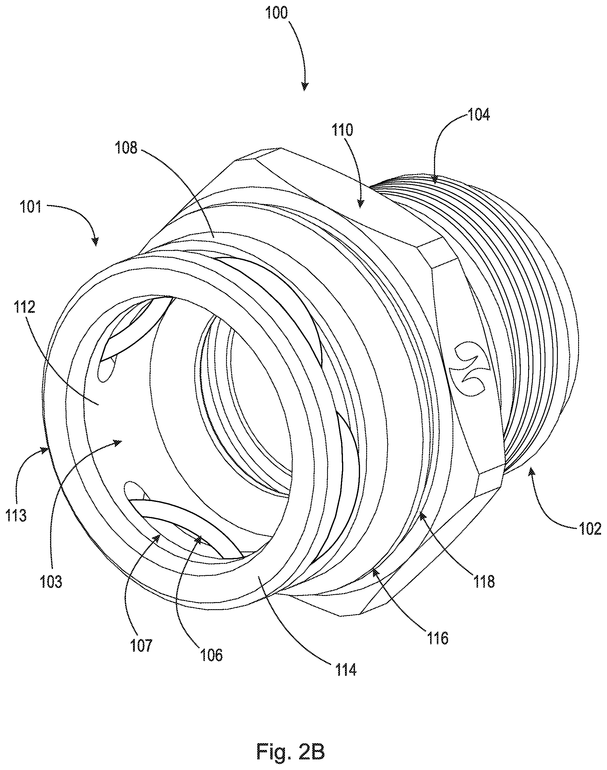
FIG. 2B is a rear perspective view of the fluid connector;
FIG. 3A is a front perspective view of the first example embodiment of the assurance cap assembly;
FIG. 3B is a rear perspective view of the first example embodiment of the assurance cap assembly;
FIG. 4 is a cross-sectional view of the fluid connector and the first example embodiment of the assurance cap assembly taken generally along line 4-4 in FIG. 1;
FIG. 5 is a perspective view of a fluid connector and a second example embodiment of an assurance cap assembly;
FIG. 6A is a front perspective view of the second example embodiment of the assurance cap assembly;
FIG. 6B is a rear perspective view of the second example embodiment of the assurance cap assembly;
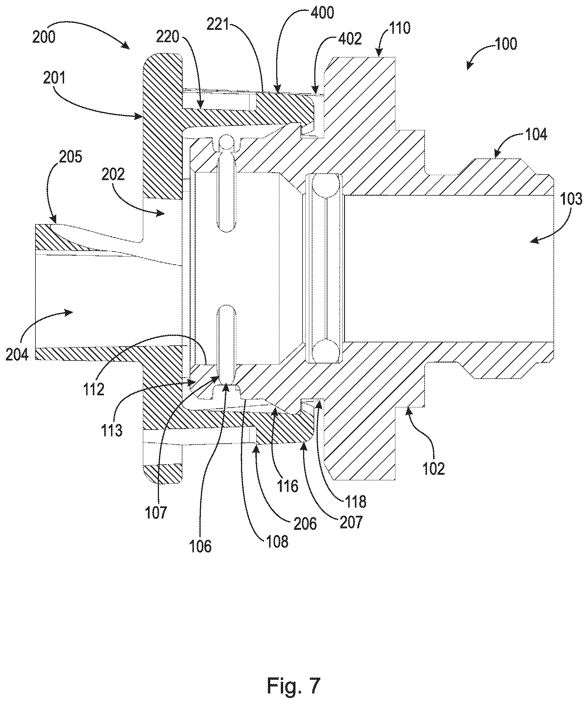
FIG. 7 is a cross-sectional view of the fluid connector and the second example embodiment of the assurance cap assembly taken generally along line 7-7 in FIG. 5;
FIG. 8 is a perspective view of a fluid connector and a third example embodiment of an assurance cap assembly;
FIG. 9A is a front perspective view of the third example embodiment of the assurance cap assembly;
FIG. 9B is a rear perspective view of the third example embodiment of the assurance cap assembly;
FIG. 10 is a cross-sectional view of the fluid connector and the third example embodiment of the assurance cap assembly taken generally along line 10-10 in FIG. 8;
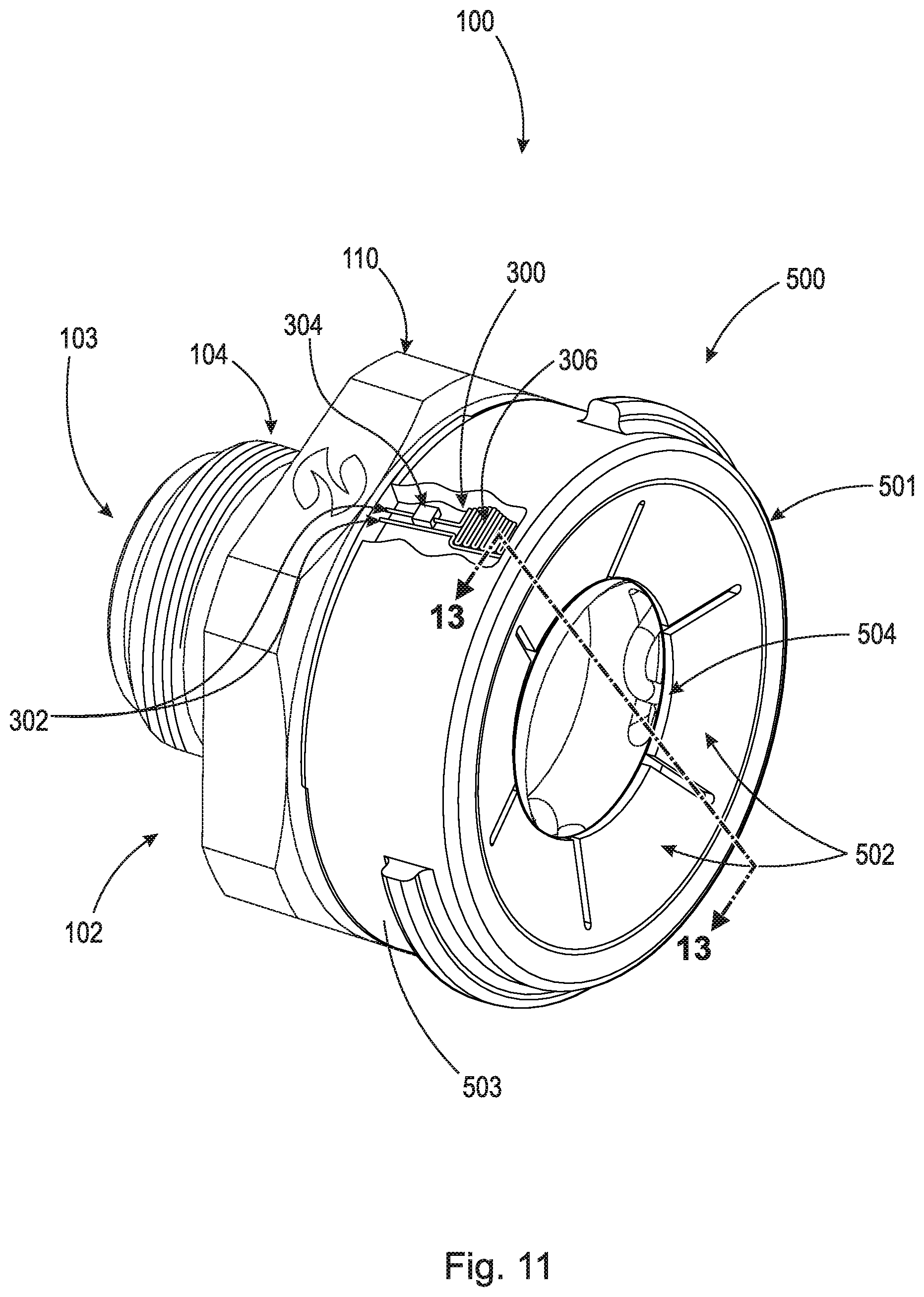
FIG. 11 is a perspective view of a fluid connector and a fourth example embodiment of the assurance cap assembly;
FIG. 12A is a front perspective view of the fourth example embodiment of the assurance cap assembly;
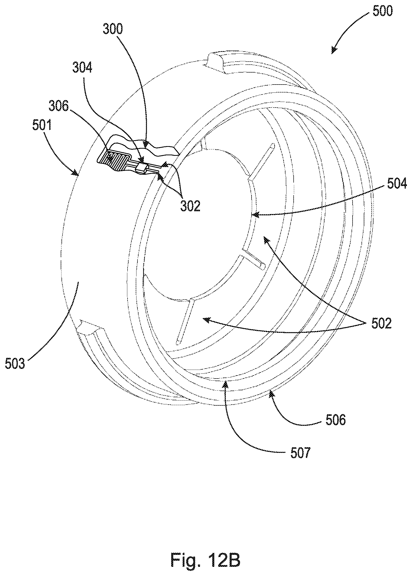
FIG. 12B is a rear perspective view of the fourth example embodiment of the assurance cap assembly;
FIG. 13 is a cross-sectional view of the fluid connector and the fourth example embodiment of the assurance cap assembly taken generally along line 13-13 in FIG. 11;
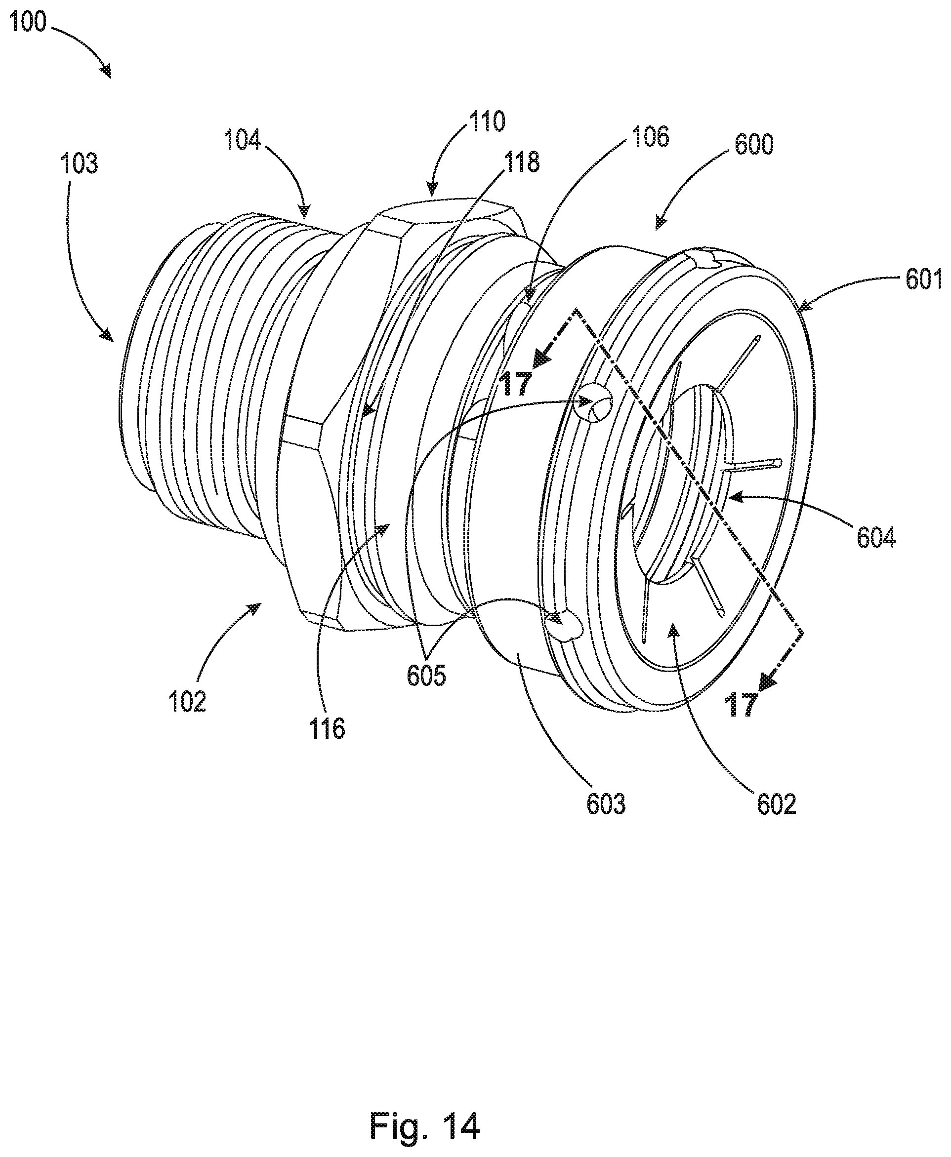
FIG. 14 is a perspective view of a fluid connector and a fifth example embodiment of an assurance cap assembly;
FIG. 15A is a front perspective view of the fifth example embodiment of the assurance cap assembly;
FIG. 15B is a rear perspective view of the fifth example embodiment of the assurance cap assembly;
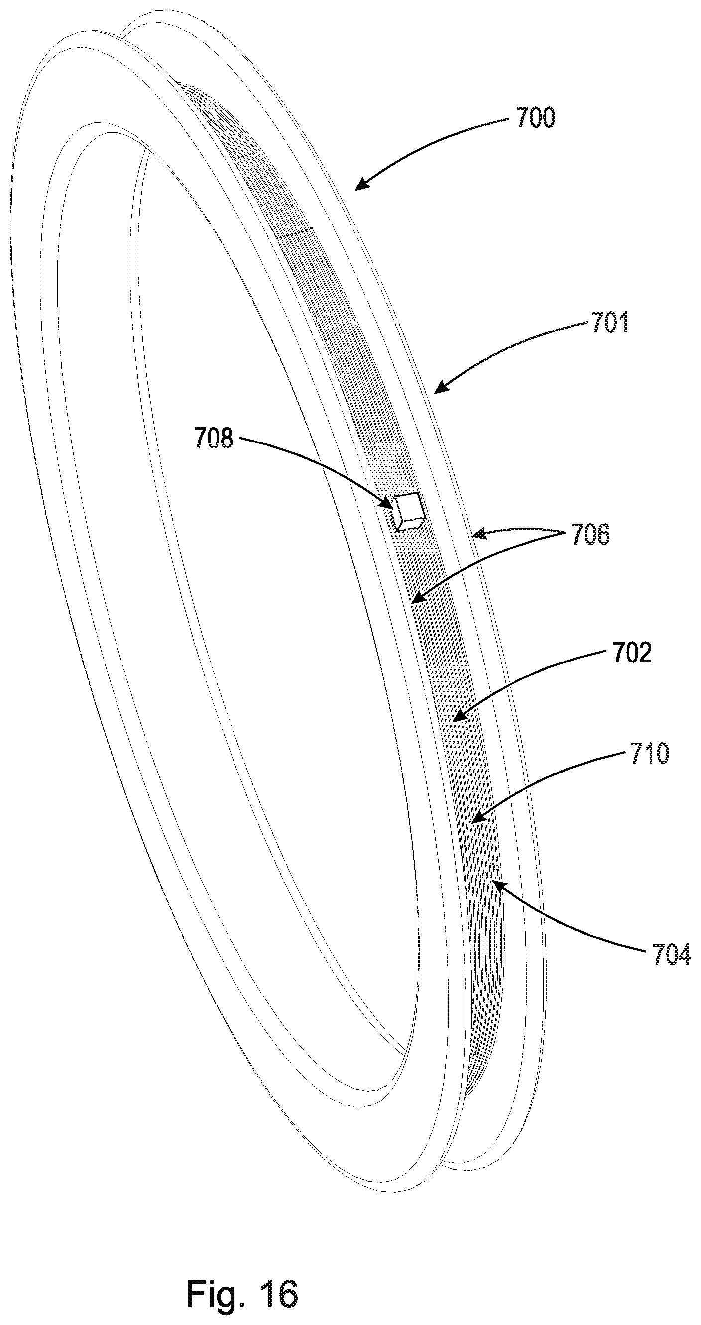
FIG. 16 is a perspective view of a sensor ring;
FIG. 17A is a cross-sectional view of the fluid connector and the fifth example embodiment of the assurance cap assembly not fully seated on the fluid connector taken generally along line 17-17 in FIG. 14; and,
FIG. 17B is a cross-sectional view of the fluid connector and the fifth example embodiment of the assurance cap assembly fully seated on the fluid connector taken generally along line 17-17 in FIG. 14.
DETAILED DESCRIPTION
At the outset, it should be appreciated that like drawing numbers on different drawing views identify identical, or functionally similar, structural elements of the disclosure. It is to be understood that this disclosure is not limited to the disclosed aspects.
Furthermore, it is understood that this disclosure is not limited to the particular methodology, materials and modifications described and, as such, may, of course, vary. It is also understood that the terminology used herein is for the purpose of describing particular aspects only, and is not intended to limit the scope of the claims.
Unless defined otherwise, all technical and scientific terms used herein have the same meaning as commonly understood to one of ordinary skill in the art to which this disclosure pertains.
Furthermore, as used herein, "and/or" is intended to mean a grammatical conjunction used to indicate that one or more of the elements or conditions recited may be included or occur. For example, a device comprising a first element, a second element and/or a third element, is intended to be construed as any one of the following structural arrangements: a device comprising a first element; a device comprising a second element; a device comprising a third element; a device comprising a first element and a second element; a device comprising a first element and a third element; a device comprising a first element, a second element and a third element; or, a device comprising a second element and a third element.
Adverting now to the figures, FIG. 1 is a perspective view of fluid connector 100 and a first example embodiment of assurance cap assembly 200. Assurance cap assembly 200 secures to fluid connector 100 on section 101 (shown in FIG. 2). Section 102 of fluid connector 100 comprises threads 104 which allow fluid connector 100 to secure to an apparatus such as a transmission, radiator, oil cooler, etc. Fluid connector 100 also includes head 110 which allows a user to use a tool such as a wrench to screw fluid connector 100 into a corresponding apparatus (not shown). Through-bore 103 (shown in FIG. 2) is arranged in the center of fluid connector 100 and passes through the whole body of fluid connector 100.
FIG. 2A and FIG. 2B are a front perspective view and a rear perspective view, respectively, of fluid connector 100. Fluid connector 100 comprises section 101 and section 102. Section 101 includes snap ring 106, outer surface 108, inner surface 112, shoulder 113, shoulder surface 114, shoulder 116, and channel 118. Snap ring 106 is arranged within apertures 107 of fluid connector 100 and secures tubular connector 800 (shown in FIG. 4) within through-bore 103 of fluid connector 100.
FIG. 3A and FIG. 3B are a front perspective view and a rear perspective view, respectively, of the first example embodiment of assurance cap assembly 200. Assurance cap assembly 200 broadly comprises body 201, channel 202, through-bore 204, lips 205, arms 206, tabs 207, sensor arm 210, surface 211, and sensor circuit 300. Channel 202 is arranged to allow tubular connector 800 (shown in FIG. 4) and a hose to be concentrically arranged within body 201. Tubular connector 800 (shown in FIG. 4) is arranged within channel 202 and then pressed into through-bore 204, deforming lips 205. Once tubular connector 800 (shown in FIG. 4) is arranged within through-bore 204, lips 205 return to their original position to further secure tubular connector 800 within through-bore 204. Arms 206 extend axially from body 201 and are operatively arranged to secure assurance cap assembly 200 to fluid connector 100. Tabs 207 are operatively arranged on the distal ends of arms 206. The geometry of arms 206 and tabs 207 allow for tabs 207 to deform around shoulder 116 and secure within channel 118 of fluid connector 100. This interaction between channel 118 and tabs 207 secure assurance cap assembly 200 to fluid connector 100. Sensor arm 210 houses sensor circuit 300, with sensor circuit 300 embedded within sensor arm 210. Sensor arm 210 is show as a cutaway in order to improve clarity of sensor circuit 300. Sensor circuit 300 comprises circuit leads 302, RFID chip 304, and antenna 306. Circuit leads 302 axial extend and protrude from surface 211 of sensor arm 210. Additionally, circuit leads 302 are operatively arranged to not engage one another in such a way which would complete and allow electricity to flow through sensor circuit 300.
FIG. 4 is a cross-sectional view of fluid connector 100 and the first example embodiment of assurance cap assembly 200 taken generally along line 4-4 in FIG. 1. As shown in the figure, sensor circuit 300 only activates when circuit leads 302 are in contact with fluid connector 100. In an example embodiment, fluid connector 100 is made of an electrical conducting material such as metal. However, it should be appreciated that fluid connector 100 only requires an electrical conducting section to complete sensor circuit 300. The electrical conducting section only needs to be arranged on fluid connector 100 in such a way as to allow circuit leads 302 to complete sensor circuit 300. An example of an electrical conducting section of fluid connector 100 comprises head 110 made of an electrical conducting material, while the remainder of fluid connector 100 is made of a non-conducting material such as plastic. In order for circuit leads 302 to reach fluid connector 100, tabs 207 must be arranged within channel 118. If tabs 207 are not arranged within channel 118, assurance cap assembly 200 is not properly seated on fluid connector 100. If assurance cap assembly 200 is not properly seated on fluid connector 100, then sensor circuit 300 will not be completed and RFID chip 304 will be unable to be scanned by an RFID reader by a technician during installation of assurance cap assembly 200. This lack of a reading is an indication to the technician that assurance cap assembly 200 is not properly seated on fluid connector 100 and must be reset. The completion of sensor circuit 300 due to the contact of circuit leads 302 with fluid connector 100 is due to the geometry of shoulder 116, channel 118, arms 206, tabs 207, sensor arm 210 and sensor circuit 300. Tubular connector 800 is represented in FIG. 4 as a dashed outline for clarity. It should be understood that tubular connector 800 is a solid body arranged within the assembly. Additionally, it should be understood that tubular connector 800 is arranged in each and every embodiment of an assurance cap assembly contained within this disclosure.
FIG. 5 is a perspective view of fluid connector 100 and a second example embodiment of assurance cap assembly 200. The second example embodiment of assurance cap assembly 200 is structurally substantially identical to the first example embodiment of assurance cap assembly 200 except for the sensor which is placed on the assurance cap assembly. The second example embodiment of assurance cap assembly 200 includes sensor circuit 400. Sensor circuit 400 comprises circuit leads 402, RFID chip 404, and antenna 406. Circuit leads 402 axially extend and protrude from sensor arm 220. Additionally, circuit leads 402 are operatively arranged to not engage one another in such a way which would complete sensor circuit 400 and allow electricity to flow through sensor circuit 400.
FIG. 6A and FIG. 6B are a front perspective view and a rear perspective view, respectively, of the second example embodiment of assurance cap assembly 200. Sensor circuit 400 is operatively arranged on surface 221 of sensor arm 220. In an example embodiment, sensor circuit 400 is arranged on a substrate prior to being placed on sensor arm 220, similar to a sticker or the like. However, it should be appreciated that sensor circuit 400 can be integral with sensor arm 220 or arranged directly on surface 221 of sensor arm 220.
FIG. 7 is a cross-sectional view of fluid connector 100 and the second example embodiment of assurance cap assembly 200 taken generally along line 7-7 in FIG. 5. As shown in the figure, sensor circuit 400 only activates when circuit leads 402 are in contact with fluid connector 100. In an example embodiment, fluid connector 100 is made of an electrical conducting material such as metal. However, it should be appreciated that fluid connector 100 only requires an electrical conducting section to complete sensor circuit 400. The electrical conducting section only needs to be arranged on fluid connector 100 in such a way as to allow circuit leads 402 to complete sensor circuit 400. An example of an electrical conducting section of fluid connector 100 comprises head 110 made of an electrical conducting material while the remainder of fluid connector 100 is made of a non-conducting material, such as plastic. In order for circuit leads 402 to reach fluid connector 100, tabs 207 must be arranged within channel 118. If tabs 207 are not arranged within channel 118, assurance cap assembly 200 is not properly seated on fluid connector 100. If assurance cap assembly 200 is not properly seated on fluid connector 100, then sensor circuit 400 will not be completed and RFID chip 404 will be unable to be scanned by an RFID reader by a technician during installation of assurance cap assembly 200. This lack of a reading is an indication to the technician that assurance cap assembly 200 is not properly seated on fluid connector 100 and must be reset. The completion of sensor circuit 400 due to the contact of circuit leads 402 with fluid connector 100 is due to the geometry of shoulder 116, channel 118, arms 206, tabs 207, sensor arm 220 and sensor circuit 400.
FIG. 8 is a perspective view of fluid connector 100 and a third example embodiment of assurance cap assembly 500.
FIG. 9A and FIG. 9B are a front perspective view and a rear perspective view, respectively, of the third example embodiment of assurance cap assembly 500. Assurance cap assembly 500 broadly includes body 501, tabs 502, surface 503, through-bore 504, edge 506, tab 507, and sensor circuit 400. Tabs 502 further secure tubular connector 800 and/or hose concentrically within through-bore 504. Sensor circuit 400 is operatively arranged on surface 503 of body 501. In an example embodiment, sensor circuit 400 is arranged on a substrate prior to being placed on surface 503, similar to a sticker or the like. However, it should be appreciated that sensor circuit 400 can be integral with body 501 or arranged directly on surface 503 of body 501.
FIG. 10 is a cross-sectional view of fluid connector 100 and the third example embodiment of assurance cap assembly 500 taken generally along line 10-10 in FIG. 8. Assurance cap assembly 500 secures to fluid connector 100 via tab 507 operatively arranged on edge 506. Tab 507 extends radially inward and secures within channel 118 of fluid connector 100. Assurance cap assembly 500 is manufactured from a material which allows tab 507 to deform enough to move past shoulder 116 of fluid connector 100 when assurance cap assembly 500 is assembled on fluid connector 100. As shown in the figure, sensor circuit 400 only activates when circuit leads 402 are in contact with fluid connector 100. In order for circuit leads 402 to reach fluid connector 100, tab 507 must be arranged within channel 118. If tab 507 is not arranged within channel 118, assurance cap assembly 500 is not properly seated on fluid connector 100. If assurance cap assembly 500 is not properly seated on fluid connector 100, then sensor circuit 400 will not be completed and will be unable to be scanned by an RFID reader by a technician during installation of assurance cap assembly 500. This lack of a reading is an indication to the technician that assurance cap assembly 500 is not properly seated on fluid connector 100 and must be reset. The completion of sensor circuit 400 due to the contact of circuit leads 402 with fluid connector 100 is due to the geometry of shoulder 116, channel 118, edge 506, tab 507, and sensor circuit 400.
FIG. 11 is a perspective view of fluid connector 100 and a fourth example embodiment of assurance cap assembly 500. The fourth example embodiment of assurance cap assembly 500 is structurally substantially identical to the third example embodiment of assurance cap assembly 500 except for the sensor which is placed on the assurance cap assembly. The fourth example embodiment of assurance cap assembly 500 includes sensor circuit 300.
FIG. 12A and FIG. 12B are a front perspective view and a rear perspective view, respectively, of the fourth example embodiment of assurance cap assembly 500. Surface 503 is show as a cutaway in order to improve clarity of sensor circuit 300. Sensor circuit 300 comprises circuit leads 302, RFID chip 304, and antenna 306. Circuit leads 302 axial extend and protrude from edge 506 of body 501. Additionally, circuit leads 302 are operatively arranged to not engage one another in such a way which would complete sensor circuit 300 and allow electricity to flow through sensor circuit 300.
FIG. 13 is a cross-sectional view of fluid connector 100 and the fourth example embodiment of assurance cap assembly 500 taken generally along line 13-13 in FIG. 11. As shown in the figure, sensor circuit 300 only activates when circuit leads 302 are in contact with fluid connector 100. The electrical conducting section only needs to be arranged on fluid connector 100 in such a way as to allow circuit leads 302 to complete sensor circuit 300. In order for circuit leads 302 to reach fluid connector 100, tab 507 must be arranged within channel 118. If tabs 507 are not arranged within channel 118, assurance cap assembly 500 is not properly seated on fluid connector 100. If assurance cap assembly 500 is not properly seated on fluid connector 100, then sensor circuit 300 will not be completed and RFID chip 304 will be unable to be scanned by an RFID reader by a technician during installation of assurance cap assembly 500. This lack of a reading is an indication to the technician that assurance cap assembly 500 is not properly seated on fluid connector 100 and must be reset. The completion of sensor circuit 400 due to the contact of circuit leads 302 with fluid connector 100 is due to the geometry of shoulder 116, channel 118, edge 506, tab 507, and sensor circuit 300.
FIG. 14 is a perspective view of fluid connector 100 and a fifth example embodiment of assurance cap assembly 600. The fifth example embodiment of assurance cap assembly 600 is structurally substantially identical to the third example embodiment of assurance cap assembly 500 except for addition of apertures 605 and the sensor which is corresponding to the assurance cap assembly. The fifth example embodiment of assurance cap assembly 600 includes sensor ring 700 operatively arranged in through-bore 604 of assurance cap assembly 600.
FIG. 15A and FIG. 15B are a front perspective view and a rear perspective view, respectively, of the fifth example embodiment of assurance cap assembly 600. Assurance cap assembly 600 broadly includes body 601, tabs 602, surface 603, through-bore 604, apertures 605, edge 606, tab 607, and sensor ring 700. Tabs 602 further secure tubular connector 800 and/or a hose concentrically within through-bore 604. Sensor ring 700 is slidably arranged on surface 608 of body 601. Tab 607 extends radially inward from edge 606 and secures within channel 118 of fluid connector 110 (shown in FIG. 17B) when assurance cap assembly 600 is properly seated on fluid connector 100.
FIG. 16 is a perspective view of sensor ring 700. Sensor ring 700 broadly includes body 701, sensor circuit 702, channel 704, and shoulders 706. Sensor circuit 702 includes RFID chip 708 and antenna 710. Unlike the previous assurance cap example embodiments, sensor circuit 702 is a completed and connected RFID circuit which allows for scanning of sensor circuit 702 with an RFID scanner.
FIG. 17A is a cross-sectional view of fluid connector 100 and the fifth example embodiment of assurance cap assembly 600 not fully seated on fluid connector 100 taken generally along line 17-17 in FIG. 14. When body 601 is not fully seated on fluid connector 100, sensor ring 700 is axially displaced from apertures 605. In an example embodiment, fluid connector 100 is manufactured from a metallic material which prevents the transfer of electromagnetic waves through its body. However, it should be appreciated that any material which sufficiently blocks electromagnetic waves can be used to manufacture fluid connector 100. Due to this electromagnetic signal blockage by fluid connector 100, sensor circuit 702 of sensor ring 700 cannot be scanned by a technician, giving the technician notice that assurance cap assembly 600 is not fully seated on fluid connector 100 and must be reseated.
FIG. 17B is a cross-sectional view of fluid connector 100 and the fifth example embodiment of assurance cap assembly 600 fully seated on fluid connector 100 taken generally along line 17-17 in FIG. 14. Once assurance cap assembly is placed on fluid connector 100, a technician then axially slides assurance cap assembly 600 towards fluid connector 100. This sliding motion causes on of shoulders 706 of sensor ring 700 to abut against surface 114 of shoulder 113 of fluid connector 100. This interaction between shoulder 113 and shoulder 706 causes sensor ring 700 to axially remain in place as body 601 is axially displaced towards fluid connector 100. In a final assembled state, sensor ring 700 is axially aligned with apertures 605 to allow sensor circuit to interact with an RFID scanner. Apertures 605 allow for electromagnetic waves to reach sensor circuit 702 once sensor ring is in the correct axial position. Once sensor ring 700 is in the correct axial position and sensor ring 702 can be scanned, this indicates to a technician that assurance cap assembly 600 is fully seated on fluid connector 100.
In the foregoing description, example embodiments are described. The specification and drawings are accordingly to be regarded in an illustrative rather than a restrictive sense.
It will be appreciated that various aspects of the above-disclosed disclosure and other features and functions, or alternatives thereof, may be desirably combined into many other different systems or applications. Various presently unforeseen or unanticipated alternatives, modifications, variations, or improvements therein may be subsequently made by those skilled in the art which are also intended to be encompassed by the following claims.
LIST OF REFERENCE NUMERALS
100 Fluid connector 101 Section 102 Section 103 Through-bore 104 Threads 106 Snap ring 107 Aperture 108 Outer surface 110 Head 112 Inner surface 113 Shoulder 114 Surface 116 Shoulder 118 Surface 200 Assurance cap assembly 201 Body 202 Channel 204 Through-bore 205 Lips 206 Arms 207 Tabs 210 Sensor arm 211 Surface 220 Sensor arm 221 Surface 300 Sensor circuit 302 Circuit leads 304 Radio frequency identification (RFID) chip 306 Antenna 400 Sensor circuit 402 Circuit leads 404 Radio frequency identification (RFID) chip 406 Antenna 500 Assurance cap assembly 501 Body 502 Tabs 503 Surface 504 Through-bore 506 Edge 507 Tab 600 Assurance cap assembly 601 Body 602 Tabs 603 Surface 604 Through-bore 605 Apertures 606 Edge 607 Tab 608 Surface 700 Sensor ring 701 Body 702 Sensor circuit 702A Radio frequency identification (RFID) chip 702B Antenna 704 Channel 706 Shoulders 708 surface Radio frequency identification (RFID) chip 710 Antenna 712 Surface 800 Tubular connector
* * * * *
D00000
D00001
D00002
D00003
D00004
D00005
D00006
D00007
D00008
D00009
D00010
D00011
D00012

D00013

D00014

D00015
D00016

D00017
D00018

D00019
D00020

D00021

D00022
D00023

D00024

XML
uspto.report is an independent third-party trademark research tool that is not affiliated, endorsed, or sponsored by the United States Patent and Trademark Office (USPTO) or any other governmental organization. The information provided by uspto.report is based on publicly available data at the time of writing and is intended for informational purposes only.
While we strive to provide accurate and up-to-date information, we do not guarantee the accuracy, completeness, reliability, or suitability of the information displayed on this site. The use of this site is at your own risk. Any reliance you place on such information is therefore strictly at your own risk.
All official trademark data, including owner information, should be verified by visiting the official USPTO website at www.uspto.gov. This site is not intended to replace professional legal advice and should not be used as a substitute for consulting with a legal professional who is knowledgeable about trademark law.