Expandable intervertebral cage
Jimenez , et al.
U.S. patent number 10,687,963 [Application Number 15/999,514] was granted by the patent office on 2020-06-23 for expandable intervertebral cage. This patent grant is currently assigned to EX TECHNOLOGY, LLC. The grantee listed for this patent is Ex Technology, LLC. Invention is credited to Omar F. Jimenez, Yefim Safris.


View All Diagrams
| United States Patent | 10,687,963 |
| Jimenez , et al. | June 23, 2020 |
Expandable intervertebral cage
Abstract
An expandable intervertebral cage device includes a first base plate and a second base plate, a proximal block with internal threading that mechanically couples the first base plate and the second base plate, and a distal block comprising an internal passage. The device has exactly two arm assemblies, one on each side. Each arm assembly includes a first arm mechanically coupled to the first base plate and the distal block, and a second arm is mechanically coupled to the second base plate and the distal block. A screw is arranged partially within the internal threading of the proximal block and passes through the internal passage of the distal block, such that rotation of the screw relative to the proximal block causes a change in distance between the proximal block and the distal block, and a corresponding change in the spacing and lordosis of the device.
| Inventors: | Jimenez; Omar F. (Gering, NE), Safris; Yefim (Golden Valley, MN) | ||||||||||
|---|---|---|---|---|---|---|---|---|---|---|---|
| Applicant: |
|
||||||||||
| Assignee: | EX TECHNOLOGY, LLC (Gering,
NE) |
||||||||||
| Family ID: | 54188761 | ||||||||||
| Appl. No.: | 15/999,514 | ||||||||||
| Filed: | August 20, 2018 |
Prior Publication Data
| Document Identifier | Publication Date | |
|---|---|---|
| US 20190021870 A1 | Jan 24, 2019 | |
Related U.S. Patent Documents
| Application Number | Filing Date | Patent Number | Issue Date | ||
|---|---|---|---|---|---|
| 15591214 | May 10, 2017 | 10052214 | |||
| 15164498 | Jun 6, 2017 | 9668879 | |||
| 14585544 | Nov 8, 2016 | 9486328 | |||
| 14242451 | Jan 27, 2015 | 8940049 | |||
| Current U.S. Class: | 1/1 |
| Current CPC Class: | A61F 2/447 (20130101); A61F 2250/0009 (20130101); A61F 2002/30556 (20130101); A61F 2002/30507 (20130101); A61F 2002/30471 (20130101); A61F 2002/30593 (20130101); A61F 2250/0006 (20130101); A61F 2002/30538 (20130101) |
| Current International Class: | A61F 2/44 (20060101); A61F 2/30 (20060101) |
References Cited [Referenced By]
U.S. Patent Documents
| 283218 | August 1883 | Rycke |
| 703251 | June 1902 | Haire |
| 811344 | January 1906 | Wands |
| 1388836 | August 1921 | Ripsch et al. |
| 1500859 | July 1924 | Wright |
| 1547946 | July 1925 | Myers |
| 2106088 | January 1938 | De Tar |
| 2231221 | February 1941 | Rector |
| 2453656 | November 1948 | Bullard, III |
| 2666334 | January 1954 | Nalle |
| 2711105 | June 1955 | Williams |
| 2842976 | July 1958 | Young |
| 2891408 | June 1959 | Burt, Jr. |
| 3386128 | June 1968 | Vyvyan |
| 3449971 | June 1969 | Posh |
| 3575475 | April 1971 | Boerner |
| 3596863 | August 1971 | Kaspareck |
| 3597938 | August 1971 | Hellen |
| 3700289 | October 1972 | Bilinski et al. |
| 3700290 | October 1972 | Ensinger |
| 3708925 | January 1973 | Ainoura |
| 3709132 | January 1973 | Farrell et al. |
| 3916596 | November 1975 | Hawley |
| 3985000 | October 1976 | Hartz |
| 3988906 | November 1976 | Smith |
| 4261211 | April 1981 | Haberland |
| 4396047 | August 1983 | Balkus |
| 4478109 | October 1984 | Kobelt |
| 4516303 | May 1985 | Kloster |
| 4528864 | July 1985 | Craig |
| 4559717 | December 1985 | Scire et al. |
| 4630495 | December 1986 | Smith |
| 4691586 | September 1987 | van Leijenhorst et al. |
| 4694703 | September 1987 | Routson |
| 4869552 | September 1989 | Tolleson et al. |
| 5133108 | July 1992 | Esnault |
| 5172442 | December 1992 | Bartley et al. |
| 5181371 | January 1993 | Deworth |
| 5196857 | March 1993 | Chiappetta et al. |
| 5198932 | March 1993 | Takamura |
| 5222986 | June 1993 | Wright |
| 5313852 | May 1994 | Arena |
| 5374556 | December 1994 | Bennett et al. |
| 5439377 | August 1995 | Milanovich |
| 5445471 | August 1995 | Wexler et al. |
| 5554191 | September 1996 | Lahille et al. |
| 5645599 | July 1997 | Samani |
| 5653763 | August 1997 | Errico et al. |
| 5664457 | September 1997 | Nejati |
| 5904479 | May 1999 | Staples |
| 5960670 | October 1999 | Iverson et al. |
| 5980252 | November 1999 | Samchukov et al. |
| 5988006 | November 1999 | Fleytman |
| 6039761 | March 2000 | Li et al. |
| 6045579 | April 2000 | Hochshuler et al. |
| 6056491 | May 2000 | Hsu |
| 6080193 | June 2000 | Hochshuler et al. |
| 6136031 | October 2000 | Middleton |
| 6175989 | January 2001 | Carpentar et al. |
| 6190414 | February 2001 | Young |
| 6315797 | November 2001 | Middleton |
| 6350317 | February 2002 | Hao et al. |
| 6378172 | April 2002 | Schrage |
| 6395035 | May 2002 | Bresina et al. |
| 6454806 | September 2002 | Cohen et al. |
| 6454807 | September 2002 | Jackson |
| 6484608 | November 2002 | Ziavras |
| 6517772 | February 2003 | Woolf |
| 6554526 | April 2003 | Egelandsdal |
| 6616695 | September 2003 | Crozet et al. |
| 6641614 | November 2003 | Wagner et al. |
| 6719796 | April 2004 | Cohen et al. |
| 6752832 | June 2004 | Neumann |
| 6772479 | August 2004 | Hinkley et al. |
| 6802229 | October 2004 | Lambert |
| 6808537 | October 2004 | Michelson |
| 6863673 | March 2005 | Gerbec et al. |
| 6932844 | August 2005 | Ralph et al. |
| 6953477 | October 2005 | Berry |
| 7018415 | March 2006 | McKay |
| 7051610 | May 2006 | Stoianovici et al. |
| 7070598 | July 2006 | Lim et al. |
| 7087055 | August 2006 | Lim et al. |
| 7201751 | April 2007 | Zucherman et al. |
| 7273373 | September 2007 | Horiuchi |
| 7308747 | December 2007 | Smith et al. |
| 7316381 | January 2008 | Hacker et al. |
| 7410201 | August 2008 | Wilson et al. |
| 7425103 | September 2008 | Perez-Sanchez |
| 7431735 | October 2008 | Liu et al. |
| 7435032 | October 2008 | Murphey et al. |
| 7547325 | June 2009 | Biedermann et al. |
| 7584682 | September 2009 | Hsiao |
| 7611538 | November 2009 | Belliard et al. |
| 7632281 | December 2009 | Errico et al. |
| 7674296 | March 2010 | Rhoda et al. |
| 7682376 | March 2010 | Trieu |
| 7708779 | May 2010 | Edie et al. |
| 7712389 | May 2010 | Wang |
| 7753958 | July 2010 | Gordon et al. |
| 7758645 | July 2010 | Studer |
| 7758648 | July 2010 | Castleman et al. |
| 7892285 | February 2011 | Viker |
| 7896919 | March 2011 | Belliard et al. |
| 7901409 | March 2011 | Canaveral et al. |
| 7947078 | May 2011 | Siegal |
| 7985256 | July 2011 | Grotz et al. |
| 8057549 | November 2011 | Butterman et al. |
| 8070813 | December 2011 | Grotz et al. |
| 8088163 | January 2012 | Kleiner |
| 8192495 | June 2012 | Simpson et al. |
| 8303663 | November 2012 | Jimenez et al. |
| 8496706 | July 2013 | Ragab et al. |
| 8523944 | September 2013 | Jimenez et al. |
| 8540452 | September 2013 | Jimenez et al. |
| 8628577 | January 2014 | Jimenez |
| 8636746 | January 2014 | Jimenez et al. |
| 8771360 | July 2014 | Jimenez et al. |
| 8795366 | August 2014 | Varela |
| 8894712 | November 2014 | Varela |
| 8906100 | December 2014 | Jimenez |
| 8932302 | January 2015 | Jimenez et al. |
| 8940049 | January 2015 | Jimenez et al. |
| 9358125 | June 2016 | Jimenez et al. |
| 9381092 | July 2016 | Jimenez et al. |
| 9445917 | September 2016 | Jimenez et al. |
| 9474626 | October 2016 | Jimenez |
| 9486328 | November 2016 | Jimenez |
| 9498270 | November 2016 | Jimenez |
| 9668879 | June 2017 | Jimenez |
| 9801734 | October 2017 | Stein |
| 9820865 | November 2017 | Sharabani |
| 9867717 | January 2018 | Jimenez |
| 10052214 | August 2018 | Jimenez |
| 10060469 | August 2018 | Jimenez et al. |
| 10117757 | November 2018 | Jimenez et al. |
| 10363142 | July 2019 | McClintock |
| 10369008 | August 2019 | Jimenez et al. |
| 2002/0128716 | September 2002 | Cohen et al. |
| 2002/0138146 | September 2002 | Jackson |
| 2003/0077110 | April 2003 | Knowles |
| 2003/0233145 | December 2003 | Landry et al. |
| 2004/0049271 | March 2004 | Biedermann et al. |
| 2004/0111157 | June 2004 | Ralph et al. |
| 2004/0153156 | August 2004 | Cohen et al. |
| 2004/0193158 | September 2004 | Lim |
| 2004/0225364 | November 2004 | Richelsoph et al. |
| 2005/0000228 | January 2005 | De Sousa et al. |
| 2005/0033431 | February 2005 | Gordon et al. |
| 2005/0095384 | May 2005 | Wittmeyer, Jr. |
| 2005/0113921 | May 2005 | An et al. |
| 2005/0113924 | May 2005 | Buttermann |
| 2005/0175406 | August 2005 | Perez-Sanchez |
| 2005/0182416 | August 2005 | Lim et al. |
| 2005/0261769 | November 2005 | Moskowitz et al. |
| 2006/0004447 | January 2006 | Mastrorio et al. |
| 2006/0004455 | January 2006 | Leonard et al. |
| 2006/0025862 | February 2006 | Villiers et al. |
| 2006/0058878 | March 2006 | Michelson |
| 2006/0129244 | June 2006 | Ensign |
| 2006/0149385 | July 2006 | McKay |
| 2006/0184171 | August 2006 | Biedermann et al. |
| 2006/0247781 | November 2006 | Francis |
| 2006/0253201 | November 2006 | McLuen |
| 2006/0293752 | December 2006 | Mounmene et al. |
| 2007/0032791 | February 2007 | Greenhalgh et al. |
| 2007/0049943 | March 2007 | Moskowitz et al. |
| 2007/0083267 | April 2007 | Miz et al. |
| 2007/0093901 | April 2007 | Grotz et al. |
| 2007/0129730 | June 2007 | Woods et al. |
| 2007/0173826 | July 2007 | Canaveral |
| 2007/0185577 | August 2007 | Malek |
| 2007/0191954 | August 2007 | Hansell et al. |
| 2007/0191958 | August 2007 | Abdou |
| 2007/0198089 | August 2007 | Moskowitz et al. |
| 2007/0219634 | September 2007 | Greenhalgh et al. |
| 2007/0222100 | September 2007 | Husted et al. |
| 2007/0250171 | October 2007 | Bonin, Jr. |
| 2007/0255415 | November 2007 | Edie et al. |
| 2007/0282449 | December 2007 | de Villiers et al. |
| 2007/0288092 | December 2007 | Bambakidis |
| 2007/0293329 | December 2007 | Glimpel et al. |
| 2007/0293948 | December 2007 | Bagga et al. |
| 2008/0026903 | January 2008 | Flugrad et al. |
| 2008/0077246 | March 2008 | Fehling et al. |
| 2008/0091211 | April 2008 | Gately |
| 2008/0100179 | May 2008 | Ruggeri et al. |
| 2008/0103601 | May 2008 | Biro et al. |
| 2008/0114367 | May 2008 | Meyer |
| 2008/0140207 | June 2008 | Olmos |
| 2008/0147194 | June 2008 | Grotz et al. |
| 2008/0154266 | June 2008 | Protopsaltis et al. |
| 2008/0161920 | July 2008 | Melkent |
| 2008/0161931 | July 2008 | Perez-Cruet et al. |
| 2008/0168855 | July 2008 | Giefer et al. |
| 2008/0183204 | July 2008 | Greenhalgh et al. |
| 2008/0188941 | August 2008 | Grotz |
| 2008/0210039 | September 2008 | Brun |
| 2008/0221694 | September 2008 | Warnick et al. |
| 2008/0234736 | September 2008 | Trieu et al. |
| 2008/0281423 | November 2008 | Sheffer et al. |
| 2008/0292392 | November 2008 | Voellmer |
| 2008/0319487 | December 2008 | Fielding et al. |
| 2009/0012564 | January 2009 | Chirico et al. |
| 2009/0076614 | March 2009 | Arramon |
| 2009/0099568 | April 2009 | Lowry et al. |
| 2009/0164017 | June 2009 | Sommerich et al. |
| 2009/0210061 | August 2009 | Sledge |
| 2009/0222100 | September 2009 | Cipoletti et al. |
| 2009/0234362 | September 2009 | Blain et al. |
| 2009/0259316 | October 2009 | Ginn et al. |
| 2009/0299478 | December 2009 | Carls et al. |
| 2009/0306672 | December 2009 | Reindel et al. |
| 2010/0004688 | January 2010 | Maas et al. |
| 2010/0076557 | March 2010 | Miller |
| 2010/0082109 | April 2010 | Greenhalgh et al. |
| 2010/0094305 | April 2010 | Chang et al. |
| 2010/0161062 | June 2010 | Foley et al. |
| 2010/0185291 | July 2010 | Jimenez et al. |
| 2010/0192715 | August 2010 | Vauchel et al. |
| 2010/0209184 | August 2010 | Jimenez et al. |
| 2011/0015638 | January 2011 | Pischl et al. |
| 2011/0054616 | March 2011 | Kamran et al. |
| 2011/0093075 | April 2011 | Duplessis et al. |
| 2011/0112644 | May 2011 | Zilberstein et al. |
| 2011/0138948 | June 2011 | Jimenez et al. |
| 2011/0160861 | June 2011 | Jimenez et al. |
| 2011/0172774 | July 2011 | Varela |
| 2011/0270398 | November 2011 | Grotz et al. |
| 2012/0010653 | January 2012 | Seifert et al. |
| 2012/0029636 | February 2012 | Ragab et al. |
| 2012/0116518 | May 2012 | Grotz et al. |
| 2012/0158071 | June 2012 | Jimenez et al. |
| 2012/0185049 | July 2012 | Varela |
| 2012/0226357 | September 2012 | Varela |
| 2012/0271419 | October 2012 | Marik |
| 2012/0290094 | November 2012 | Lim et al. |
| 2012/0303124 | November 2012 | McLuen et al. |
| 2012/0323329 | December 2012 | Jimenez et al. |
| 2013/0053966 | February 2013 | Jimenez et al. |
| 2013/0144388 | June 2013 | Emery et al. |
| 2013/0158664 | June 2013 | Palmatier |
| 2013/0197642 | August 2013 | Ernst |
| 2013/0317615 | November 2013 | Jimenez et al. |
| 2014/0012383 | January 2014 | Triplett et al. |
| 2014/0018924 | January 2014 | McManus et al. |
| 2014/0039622 | February 2014 | Glerum et al. |
| 2014/0088714 | March 2014 | Miller et al. |
| 2014/0140757 | May 2014 | Jimenez et al. |
| 2014/0156007 | June 2014 | Pabst et al. |
| 2014/0194991 | July 2014 | Jimenez |
| 2014/0236296 | August 2014 | Wagner et al. |
| 2014/0249629 | September 2014 | Moskowitz et al. |
| 2014/0343608 | November 2014 | Whiton et al. |
| 2015/0018951 | January 2015 | Loebl |
| 2015/0088258 | March 2015 | Jimenez et al. |
| 2015/0100128 | April 2015 | Glerum et al. |
| 2015/0148908 | May 2015 | Marino et al. |
| 2015/0272743 | October 2015 | Jimenez et al. |
| 2015/0272745 | October 2015 | Jimenez et al. |
| 2015/0272746 | October 2015 | Jimenez et al. |
| 2015/0351925 | December 2015 | Emerick et al. |
| 2016/0166396 | June 2016 | McClintock |
| 2016/0262907 | September 2016 | Jimenez |
| 2016/0356368 | December 2016 | Jimenez et al. |
| 2016/0377113 | December 2016 | Jimenez et al. |
| 1342456 | Sep 2003 | EP | |||
| 1552797 | Jul 2005 | EP | |||
| 1881209 | Jan 2008 | EP | |||
| 2372998 | Dec 1976 | FR | |||
| 05-81194 | Apr 1993 | JP | |||
| 2004-301135 | Oct 2004 | JP | |||
| 2008-208932 | Sep 2008 | JP | |||
| WO 2004/026188 | Apr 2004 | WO | |||
| WO 2004/109155 | Dec 2004 | WO | |||
| WO 2005/081330 | Sep 2005 | WO | |||
| WO 2005/096975 | Oct 2005 | WO | |||
| WO 2006/094535 | Sep 2006 | WO | |||
| WO 2006/116052 | Nov 2006 | WO | |||
| WO 2006/125329 | Nov 2006 | WO | |||
| WO 2007/002583 | Jan 2007 | WO | |||
| WO 2007/009107 | Jan 2007 | WO | |||
| WO 2007/028140 | Mar 2007 | WO | |||
| WO 2007/076377 | Jul 2007 | WO | |||
| WO 2007/111979 | Oct 2007 | WO | |||
| WO 2008/137192 | Nov 2008 | WO | |||
| WO 2009/018349 | Feb 2009 | WO | |||
| WO 2010/078468 | Jul 2010 | WO | |||
| WO 2010/078520 | Jul 2010 | WO | |||
| WO 2011/011609 | Jan 2011 | WO | |||
| WO 2011/011626 | Jan 2011 | WO | |||
| WO 2014/066890 | May 2014 | WO | |||
Other References
|
PCT/US2010/042941, filed Jul. 22, 2010, International Search Report and Written Opinion, dated Apr. 25, 2011. cited by applicant . PCT/US2010/042915, filed Jul. 22, 2010, Search Report and Written Opinion dated Apr. 22, 2011. cited by applicant . PCT/US2009/069876, filed Dec. 30, 2009, International Search Report and Written Opinion dated Sep. 27, 2010, 10 pages. cited by applicant . PCT/US2009/069958, filed Dec. 31, 2009, International Search Report and Written Opinion dated Nov. 29, 2010, 7 pages. cited by applicant . PCT/US2015/055449, filed Oct. 14, 2015, International Search Report and Written Opinion dated Dec. 11, 2015, 9 pages. cited by applicant . PCT/US2015/032977, filed May 28, 2015, International Search Report and Written Opinion dated Sep. 21, 2015, 10 pages. cited by applicant . European Application No. EP 09837185, European Search Report dated May 14, 2013, 7 pages. cited by applicant . Japanese Application No. 2012-521784, JP Office Action dated Feb. 18, 2014, 8 pages. cited by applicant . PCT/US2013/067070, PCT Written Opinion/Search Report dated Feb. 27, 2014, 14 pages. cited by applicant . PCT/US2014/052913, PCT Written Opinion/Search Report dated Dec. 22, 2014, 10 pages. cited by applicant . European Application No. EP 10802916.6, Examination Report dated May 12, 2016, 4 pages. cited by applicant . Canadian Application No. 2,768,867, Office Action dated Aug. 4, 2016, 4 pages. cited by applicant . Canadian Application No. 2,768,867, Office Action dated Apr. 19, 2017, 4 pages. cited by applicant . Wenzel Spine, Inc., VariLift.RTM.-L Expandable Interbody Fusion Device: A proven solution for stand-alone fusion, Product Overview, 12 pages, 2010. cited by applicant . Peter A. Halverson, et. al., Tension-based Multi-stable Compliant: Rolling-contact Elements, Department of Mechanical Engineering, Brigham Young University, Provo UT, USA 84602, 34 pages, 2007. cited by applicant . Just L. Herder, Force Directed Design of Laparoscopic Forceps, ASME Design Engineering Technical Conference, 8 pages, 1998. cited by applicant . Alexander H. Slocum, Fundamentals of Design, 2005. cited by applicant . W. Kusswetter, A Supplementary Instrumentation for Posterior Fusion of Spine in Scoliosis, Archives of Orthopedic Traumatic Surgery, 1980, 1 page. cited by applicant . Chou et al., Efficacy of Anterior Cervical Fusion: Comparison of Titanium Cages, polyetheretherketone (PEEK) cages and autogenous bone grafts, Journal of Clinical Neuroscience, 2008, pp. 1240-1245. cited by applicant . Amelie Jeanneau, et. al., A Compliant Rolling Contact Joint and its Application in a 3-DOF Planar Parallel Mechanism with Kinematic Analysis, ASME, Design Engineering Technical Conferences, 9 pages, 2004. cited by applicant . Hunter et al., Overview of Medical Devices, Department of Radiology, University of Arizona, Aug. 2001, pp. 89-140, vol. 30, No. 4, ISSN: 0363-0188. cited by applicant . Medtronic Sofamor Danek USA, Inc., CAPSTONE Instrument Set Technique, http://www.mtortho.com/public/capstone.pdf, .COPYRGT. 2005, 25 pages. cited by applicant . Medtronic, CAPSTONE PEEK Spinal System Surgical Technique, http://www.mtortho.com/public/capstone_peek_st.pdf, .COPYRGT. 2009, 36 pages. cited by applicant . Website printout from https://seelio.com/w/fgf/omnilif-the-new-standard-in-spinal-deformity-cor- rection-and-fusion?student=lumbarjax; dated Nov. 27, 2014, 5 pages. cited by applicant . Printout from Video for OmniLIF Anterior Insertion Approach from Lumber Jax; https://seelio.com/w/fgf/omnilif-the-new-standard-in-spinal-deformit- y-correction-and-fusion?student=lumbarjax; dated Nov. 27, 2014, 7 pages. cited by applicant . Printout from Video for OmniLIF Features from Lumber Jax; https://seelio.com/w/fgf/omnilif-the-new-standard-in-spinal-deformity-cor- rection-and-fusion?student=lumbarjax; dated Nov. 27, 2014, 11 pages. cited by applicant . Application and File History for U.S. Appl. No. 12/407,608, filed Mar. 19, 2009, now U.S. Pat. No. 8,628,577, Inventors Jimenez et al. cited by applicant . Application and File History for U.S. Appl. No. 12/650,994, filed Dec. 31, 2009, now U.S. Pat. No. 8,523,944, Inventors Jimenez et al. cited by applicant . Application and File History for U.S. Appl. No. 12/651,266, filed Dec. 31, 2009, now U.S. Pat. No. 8,540,452, Inventors Jimenez et al. cited by applicant . Application and File History for U.S. Appl. No. 12/841,465, filed Jul. 22, 2010, now U.S. Pat. No. 8,303,663, Inventors Jimenez et al. cited by applicant . Application and File History for U.S. Appl. No. 12/841,869, filed Jul. 22, 2010, now U.S. Pat. No. 9,358,125, Inventors Jimenez et al. cited by applicant . Application and File History for U.S. Appl. No. 12/118,767, filed May 12, 2008, Inventor Jimenez. cited by applicant . Application and File History for U.S. Appl. No. 13/189,410, filed Jul. 22, 2011, now U.S. Pat. No. 8,636,746, Inventor Jimenez. cited by applicant . Application and File History for U.S. Appl. No. 13/661,534, filed Oct. 26, 2012, now U.S. Pat. No. 8,932,302, Inventor Jimenez. cited by applicant . Application and File History for U.S. Appl. No. 13/591,463, filed Aug. 22, 2012, now U.S. Pat. No. 8,771,360, Inventor Jimenez. cited by applicant . Application and File History for U.S. Appl. No. 13/891,356, filed May 10, 2013, now U.S. Pat. No. 8,906,100, Inventor Jimenez et al. cited by applicant . Application and File History for U.S. Appl. No. 14/024,764, filed Sep. 12, 2013, now U.S. Pat. No. 9,381,092, Inventor Jimenez et al. cited by applicant . Application and File History for U.S. Appl. No. 14/153,281, filed Jan. 13, 2014, now U.S. Pat. No. 9,867,717, Inventor Jimenez. cited by applicant . Application and File History for U.S. Appl. No. 14/563,660, filed Dec. 8, 2014, now U.S. Pat. No. 9,445,917, Inventor Jimenez et al. cited by applicant . Application and File History for U.S. Appl. No. 14/242,451, filed Apr. 1, 2014, now U.S. Pat. No. 8,940,049, Inventor Jimenez et al. cited by applicant . Application and File History for U.S. Appl. No. 14/318,196, filed Jun. 27, 2014, now U.S. Pat. No. 9,474,626. Inventor Jimenez et al. cited by applicant . Application and File History for U.S. Appl. No. 14/592,507, filed Jan. 8, 2015, now U.S. Pat. No. 9,498,270. Inventor Jimenez et al. cited by applicant . Application and File History for U.S. Appl. No. 14/585,544, filed Dec. 30, 2014, now U.S. Pat. No. 9,486,328. Inventor Jimenez et al. cited by applicant . Application and File history for U.S. Appl. No. 15/164,498, filed May 25, 2016, now U.S. Pat. No. 9,668,879. Inventors: Jimenez et al. cited by applicant . Application and File history for U.S. Appl. No. 15/174,454, filed Jun. 6, 2016, now U.S. Pat. No. 10,117,757. Inventors: Jimenez et al. cited by applicant . Application and File history for U.S. Appl. No. 15/332,066, filed Oct. 24, 2016, now U.S. Pat. No. 10,369,008. Inventors: Jimenez et al. cited by applicant . Application and File history for U.S. Appl. No. 15/198,557, filed Jun. 30, 2016, now U.S. Pat. No. 10,060,469. Inventors: Jimenez et al. cited by applicant . Application and File history for U.S. Appl. No. 15/591,214, filed May 10, 2017, now U.S. Pat. No. 10,052,214. Inventor(s): Jimenez et al. cited by applicant . European Application No. EP14887838.2, Extended European Search Report, dated Oct. 25, 2017, 8 pages. cited by applicant . European Application No. 15875858.1, Extended European Search Report, dated Jun. 22, 2018, 9 pages. cited by applicant. |
Primary Examiner: Plionis; Nicholas J
Attorney, Agent or Firm: Patterson Thuente Pedersen, P.A.
Parent Case Text
RELATED APPLICATIONS
The present application is a Continuation of U.S. patent application Ser. No. 15/591,214 entitled "EXPANDABLE INTERVERTEBRAL CAGE", filed May 10, 2017, which is a Continuation of U.S. patent application Ser. No. 15/164,498 entitled "EXPANDABLE INTERVERTEBRAL CAGE", filed May 25, 2016, which is a Continuation of U.S. patent application Ser. No. 14/585,544 entitled "EXPANDABLE INTERVERTEBRAL CAGE", filed Dec. 30, 2014, which is a Continuation in Part of U.S. patent application Ser. No. 14/242,451 entitled "EXPANDABLE INTERVERTEBRAL CAGE", filed Apr. 1, 2014, all of which are incorporated herein by reference in their entireties. This application is also related to PCT Application No. PCT/US2014/052913 entitled "EXPANDABLE INTERVERTEBRAL CAGE," filed Aug. 27, 2014.
Claims
What is claimed is:
1. An expandable intervertebral cage device adapted to be implanted into an intervertebral disc space in a patient's body, comprising: a first base plate having a first outer bearing surface configured to interface with a first vertebra of the intervertebral disc space, the first base plate including a first rod extending through a proximal pivot structure and a proximal end of the first base plate; a second base plate having a second outer bearing surface configured to interface with a second vertebra of the intervertebral disc space, the second base plate including a second rod extending through the proximal pivot structure and a proximal end of the second base plate; only a single arm assembly extending between the first base plate and the second base plate on each of a first side of the device and a second side of the device, each arm assembly including only a pair of arms, a first arm of the pair of arms pivotally coupled to the first base plate and not coupled to the second base plate and a second arm of the pair of arms pivotally coupled to the second base plate and not coupled to the first base plate, wherein each of the first arm and the second arm is pivotally coupled to a distal pivot structure distinct from the proximal pivot structure, the distal pivot structure disposed between the first base plate and the second base plate; and an actuation member extending longitudinally within a space between the first base plate and the second base plate, wherein rotation of the actuation member in a first direction causes the arm assemblies to expand and the rotation of the actuation member in a second direction causes the arm assemblies to contract, and wherein expansion of the arm assemblies causes the first base plate to pivot about the first rod and the second base plate to pivot about the second rod to cause the first base plate and the second base plate to be angled relative to one another.
2. The device of claim 1, wherein a distance between the proximal end of the first base plate and the proximal end of the second base plate remains generally constant as the arm assemblies are expanded.
3. The device of claim 1, wherein at a maximum expansion of the arm assemblies each base plate defines an angle of 23 degrees.
4. The device of claim 1, wherein the first base plate and the second base plate each have an opening defined therein configured to allow bone growth into an open space defined by the device.
5. The device of claim 1, wherein the actuation member includes a first portion having a first diameter and a second portion having a second diameter different from the first diameter.
6. The device of claim 1, wherein each arm comprises only a single rigid member.
7. The device of claim 1, wherein the distal pivot structure defines an internal passage into which the actuation member extends.
8. The device of claim 7, wherein the actuation member is longitudinally fixed with respect to the distal pivot structure such that longitudinal movement of the actuation member causes a corresponding longitudinal movement of the distal pivot structure.
9. The device of claim 1, wherein the distal pivot structure is not directly connected to either the first base plate or the second base plate.
10. The device of claim 1, wherein the actuation member is not connected to the first arm or the second arm of either arm assembly.
11. An expandable intervertebral cage device adapted to be implanted into an intervertebral disc space in a patient's body, comprising: a first member having a first outer bearing surface configured to interface with a first vertebra of the intervertebral disc space, and further including a first fixed pivot where a proximal end of the first member is pivotally coupled to a proximal pivot structure a second member having a second outer bearing surface configured to interface with a second vertebra of the intervertebral disc space, and further including a second fixed pivot point where a proximal end of the second member is pivotally coupled to the proximal pivot structure; only a single arm assembly extending between the first member and the second member on each of a first side of the device and a second side of the device, each arm assembly including only a pair of arms each comprising only a single rigid member, a first arm of the pair of arms pivotally coupled to the first member and a second arm of the pair of arms pivotally coupled to the second member, wherein each of the first arm and the second arm is pivotally coupled to a distal pivot structure distinct from the proximal pivot structure, the distal pivot structure disposed between the first member and the second member; and an actuation member extending longitudinally within a space between the first member and the second member, wherein rotation of the actuation member in a first direction causes the arm assemblies to expand and rotation of the actuation in a second direction causes the arm assemblies to contract, and wherein expansion of the arm assemblies causes the first member to pivot about the first fixed pivot point and the second member to pivot about the second fixed pivot point to cause the first member and the second member to be angled relative to one another.
12. The device of claim 11, wherein the distal pivot structure defines an internal passage into which the actuation member extends.
13. The device of claim 12, wherein the actuation member is longitudinally fixed with respect to the distal pivot structure such that longitudinal movement of the actuation member causes a corresponding longitudinal movement of the distal pivot structure.
14. The device of claim 11, wherein the distal pivot structure is not directly connected to either the first member or the second member.
15. The device of claim 11, wherein a distance between the proximal end of the first member and the proximal end of the second member remains generally constant as the arm assemblies are expanded.
16. The device of claim 11, wherein at a maximum expansion of the arm assemblies each member defines an angle of 23 degrees.
17. The device of claim 11, wherein the first member and the second member each have an opening defined therein configured to allow bone growth into an open space defined by the device.
18. The device of claim 11, wherein the actuation member includes a first portion having a first diameter and a second portion having a second diameter different from the first diameter.
19. The device of claim 11, wherein the first arm is not coupled to the second member and the second arm is not coupled to the first member.
20. The device of claim 11, wherein the actuation member is not connected to the first arm or the second arm of either arm assembly.
Description
TECHNICAL FIELD
The present invention relates to the distraction and fusion of vertebral bodies. More specifically, the present invention relates to devices and associated methods for distraction and fusion of vertebral bodies that remain stable when implanted and facilitate fusion following their use for distraction to aid in the correction of spinal deformity by reducing a collapsed disc and establishing sagittal alignment, lordosis, or kyphosis.
BACKGROUND
The concept of intervertebral fusion for the cervical and lumbar spine following a discectomy was generally introduced in the 1960s. It involved coring out a bone graft from the hip and implanting the graft into the disc space. The disc space was prepared by coring out the space to match the implant. The advantages of this concept were that it provided a large surface area of bone to bone contact and placed the graft under loading forces that allowed osteoconduction and induction enhancing bone fusion. However, the technique is seldom practiced today due to numerous disadvantages including lengthy operation time, destruction of a large portion of the disc space, high risk of nerve injury, and hip pain after harvesting the bone graft.
Presently, at least two devices are commonly used to perform the intervertebral portion of an intervertebral body fusion: the first is the distraction device and the second is the intervertebral body fusion device, often referred to as a cage. Cages can be implanted as standalone devices or as part of a circumferential fusion approach with pedicle screws and rods. The concept is to introduce an implant that will distract a collapsed disc and decompress the nerve root, allow load sharing to enhance bone formation and to implant a device that is small enough to allow implantation with minimal retraction and pulling on nerves.
In a typical intervertebral body fusion procedure, a portion of the intervertebral disc is first removed from between the vertebral bodies. This can be done through either a direct open approach or a minimally invasive approach. Disc shavers, pituitary rongeours, curettes, and/or disc scrapers can be used to remove the nucleus and a portion of either the anterior or posterior annulus to allow implantation and access to the inner disc space. The distraction device is inserted into the cleared space to enlarge the disc space and the vertebral bodies are separated by actuating the distraction device. Enlarging the disc space is important because it also opens the foramen where the nerve root exists. It is important that during the distraction process one does not over-distract the facet joints. An intervertebral fusion device is next inserted into the distracted space and bone growth factor, such as autograft, a collagen sponge with bone morphogenetic protein, or other bone enhancing substance may be inserted into the space within the intervertebral fusion device to promote the fusion of the vertebral bodies.
Intervertebral fusion and distraction can be performed through anterior, posterior, oblique, and lateral approaches. Each approach has its own anatomical challenges, but the general concept is to fuse adjacent vertebra in the cervical thoracic or lumbar spine. Devices have been made from various materials. Such materials include cadaveric cancellous bone, carbon fiber, titanium, and polyetheretherketone (PEEK). Devices have also been made into different shapes such as a bean shape, football shape, banana shape, wedge shape, and a threaded cylindrical cage.
U.S. Pat. Nos. 7,070,598 and 7,087,055 to Lim et al. disclose minimally invasive devices for distracting the disc space. The devices include scissor-jack-like linkages that are used to distract a pair of endplates associated with adjacent vertebra from a first collapsed orientation to a second expanded orientation. A pull arm device is used to deliver and distract the device in the disc space. However, the device is primarily used for distraction and not subsequent vertebral fusion. The device would not work as a fusion device, because once the pull arm is disconnected from the device, the device will not be stable enough to maintain proper spacing of the vertebrae until fusion can occur. The endplates of the device are also solid and do not permit bone growth for successful fusion.
U.S. Patent Publication No. 2008/0114367 to Meyer discloses a device that uses a scissor-jack-like arrangement to distract a disc space. To solve the instability problem of the scissor-jack arrangement, a curable polymer is injected to fill the disc space and the distraction device is disabled from attempting to support the load. The curable polymer and disabling of the device are necessary because the device could not adequately support the distracted disc space. The base plates of the device have at least two or more degrees of freedom, collectively, in a distracted position and are therefore not stable under the loads encountered supporting the disc space. Absent injection of the polymer, and the support and control supplied by the implanting physician via the removable distraction tool, the base plates would collapse, which could cause severe damage to the vertebral bodies.
Accordingly, there is a need in the art for a device that can distract adjacent vertebral bodies in a minimally invasive manner while providing stable support for the disc space during fusion; particularly, a device that would allow for angular orientation of the base plates to be matched exactly to the unique alignment, or desired alignment, of a patient's spine.
SUMMARY OF THE DISCLOSURE
According to an embodiment, an expandable intervertebral cage device adapted to be implanted into an intervertebral disc space in a patient's body. The device includes a first base plate having a first outer bearing surface configured to interface with a first vertebra of the intervertebral disc space, a second base plate having a second outer bearing surface configured to interface with a second vertebra of the intervertebral disc space, a proximal block mechanically coupled to the first base plate and the second base plate, wherein the proximal block comprises internal threading, a distal block comprising an internal passage, and exactly two arm assemblies, wherein a first one of the two arm assemblies is arranged on a first side of the device and a second one of the two arm assemblies is arranged on a second side of the device, wherein each of the exactly two arm assemblies comprises a first arm mechanically coupled to the first base plate and the distal block and a second arm is mechanically coupled to the second base plate and the distal block. A screw is arranged partially within the internal threading of the proximal block and passing through the internal passage of the distal block, such that rotation of the screw relative to the proximal block causes a change in distance between the proximal block and the distal block, and a corresponding change in the spacing and lordosis of the device.
BRIEF DESCRIPTION OF THE DRAWINGS
The invention may be more completely understood in consideration of the following detailed description of various embodiments of the invention in connection with the accompanying drawings, in which:
FIGS. 1A-1B are perspective views of an expandable intervertebral cage device according to an aspect of the present invention.
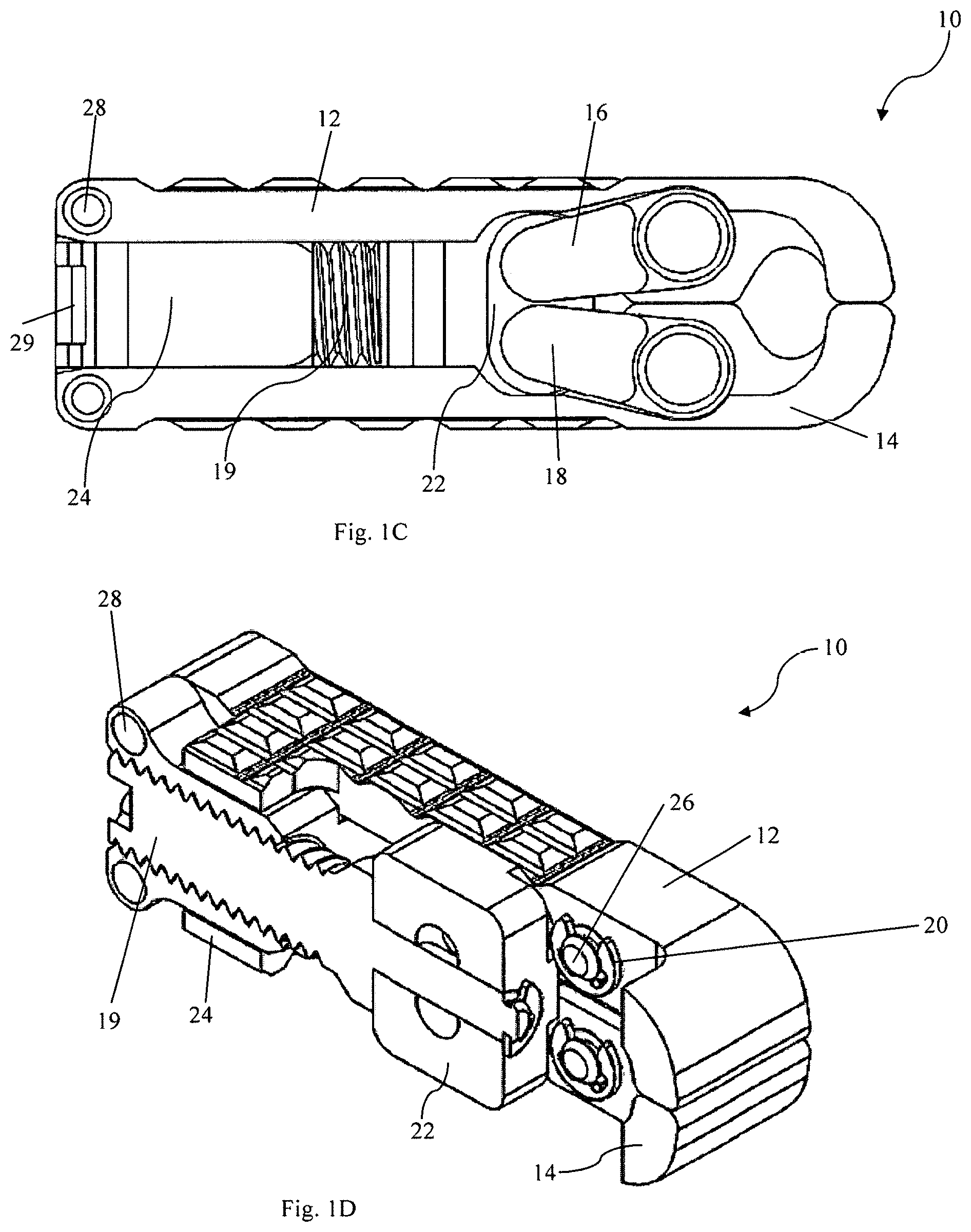
FIG. 1C is a side view of the expandable intervertebral cage device according to the embodiment of FIGS. 1A-1B.
FIG. 1D is a cross-sectional view of the intervertebral cage device according to the embodiment of FIGS. 1A-1C, taken along line 1D-1D of FIG. 1A.
FIGS. 2A-2B are perspective views of an expanded intervertebral cage device according to an embodiment.
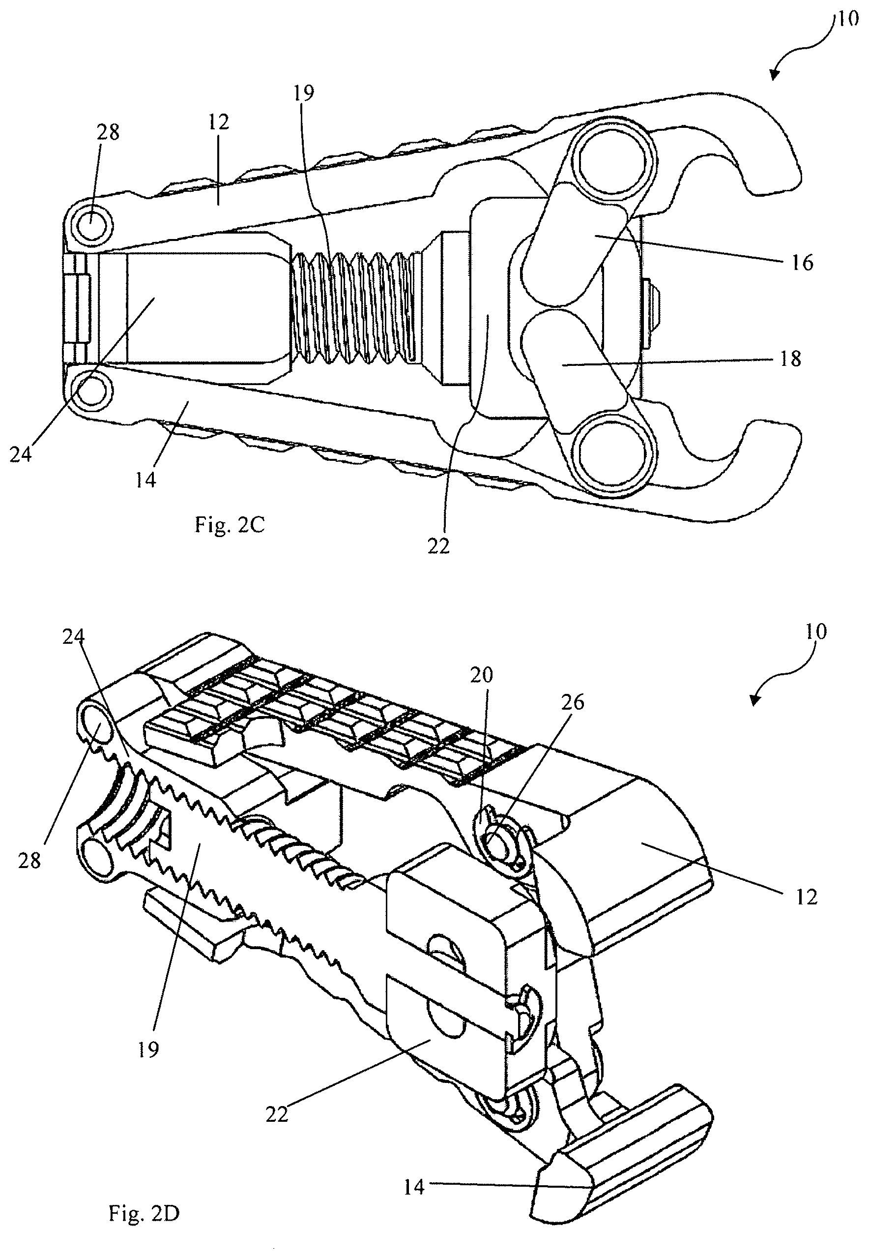
FIG. 2C is a side view of the expanded intervertebral cage device of FIGS. 2A-2B.
FIG. 2D is a cross-sectional view of the intervertebral cage device according to the embodiment of FIGS. 2A-2C, taken along line 2D-2D of FIG. 2A.
FIG. 3 is a perspective view of an end plate, according to an embodiment.
FIG. 4 is a perspective view of a side arm, according to an embodiment.
FIG. 5 is a perspective view of a ring pin, according to an embodiment.
FIG. 6 is a perspective view of a proximal block, according to an embodiment.
FIG. 7 is a perspective view of a distal block, according to an embodiment.
FIG. 8 is a perspective view of a pin, according to an embodiment.
FIG. 9 is a perspective view of a rod, according to an embodiment.
FIG. 10A is a rear view of an embodiment of an expandable intervertebral cage device according to an aspect of the present invention;
FIG. 10B is a side view of an embodiment of an expandable intervertebral cage device according to an aspect of the present invention;
FIG. 10C is a top view of an embodiment of an expandable intervertebral cage device according to an aspect of the present invention;
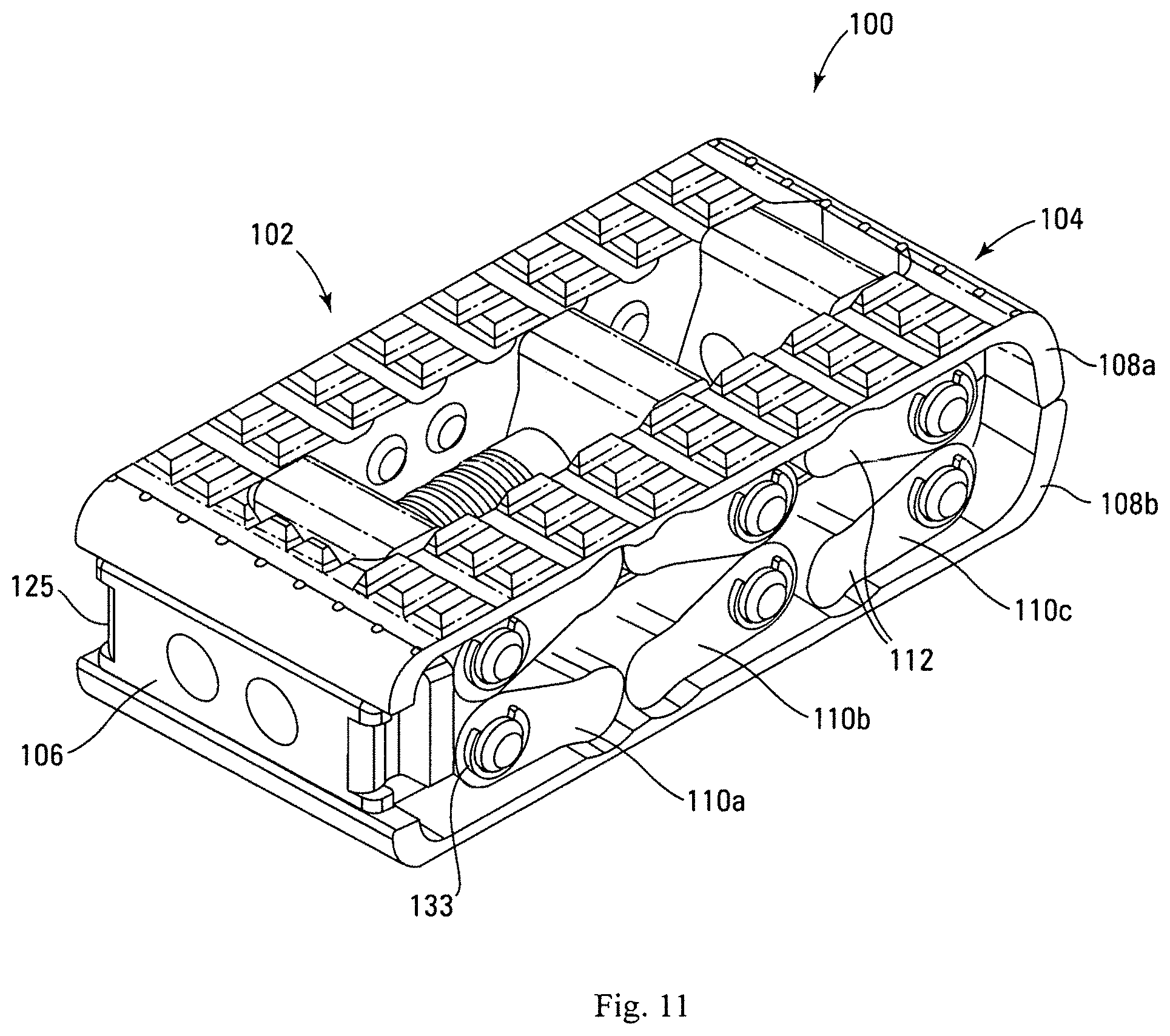
FIG. 11 is a perspective view of an embodiment of an expandable intervertebral cage device according to an aspect of the present invention;
FIG. 12A is a perspective view of an embodiment of a first base plate according to an aspect of the present invention;
FIG. 12B is a perspective view of an embodiment of a second base plate according to an aspect of the present invention;
FIG. 12C is a side view of an embodiment of a base plate according to an aspect of the present invention;
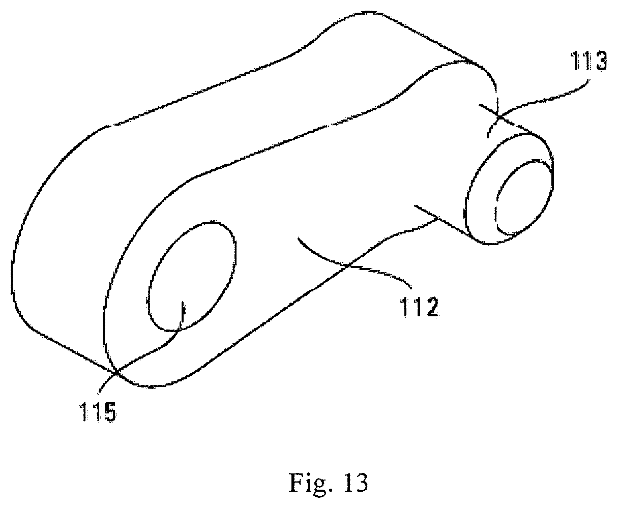
FIG. 13 is a perspective view of an embodiment of an arm according to an aspect of the present invention;
FIG. 14 is a perspective view of an embodiment of first, second and third blocks according to an aspect of the present invention;
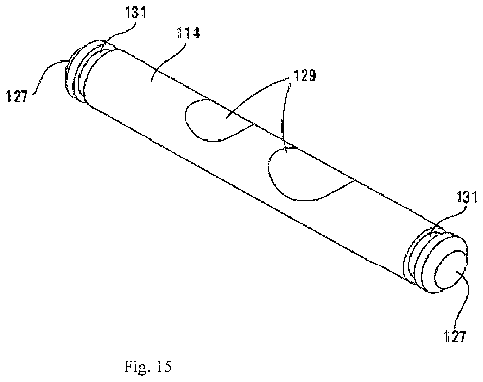
FIG. 15 is a perspective view of an embodiment of a pin according to an aspect of the present invention;
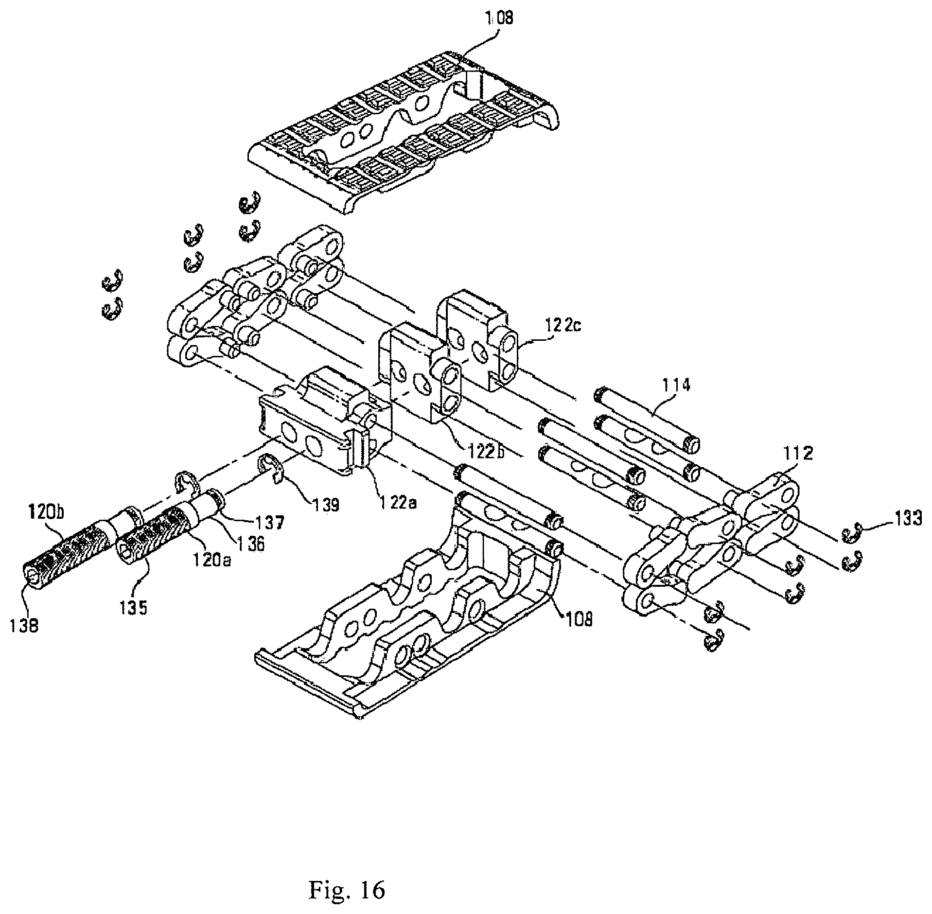
FIG. 16 is an exploded view of an embodiment of an expandable intervertebral cage device according to an aspect of the present invention;
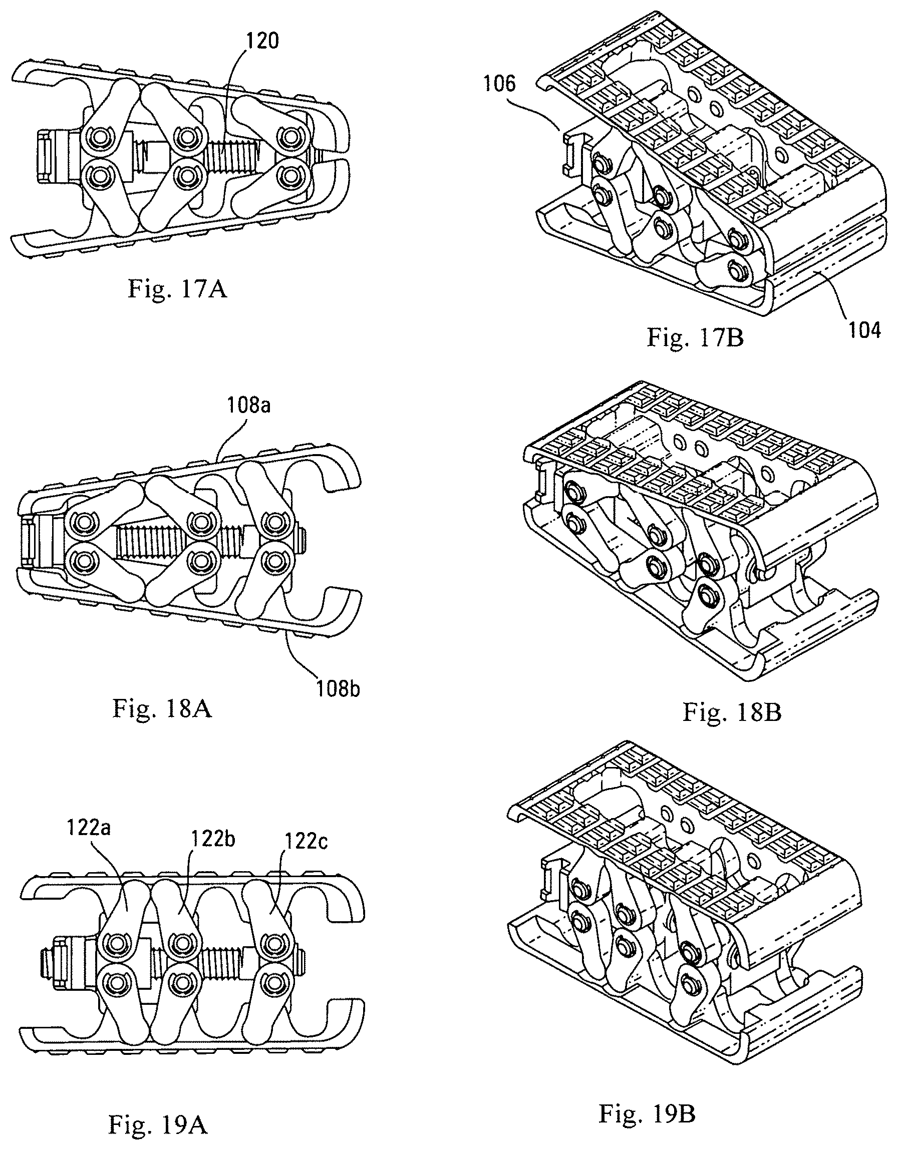
FIGS. 17A-17B are side and perspective views an embodiment of an expandable intervertebral cage device according to an aspect of the present invention in a distracted state, wherein the nose portion is further distracted that the rear portion;
FIGS. 18A-18B are side and perspective views an embodiment of an expandable intervertebral cage device according to an aspect of the present invention in a distracted state, wherein the rear portion is further distracted that the nose portion;
FIGS. 19A-19B are side and perspective views of an embodiment of an expandable intervertebral cage device according to an aspect of the present invention in a distracted state, wherein the rear portion and nose portion are substantially equally distracted;
FIG. 20 is a simplified view of an embodiment of an expandable intervertebral cage device according to an aspect of the present invention.
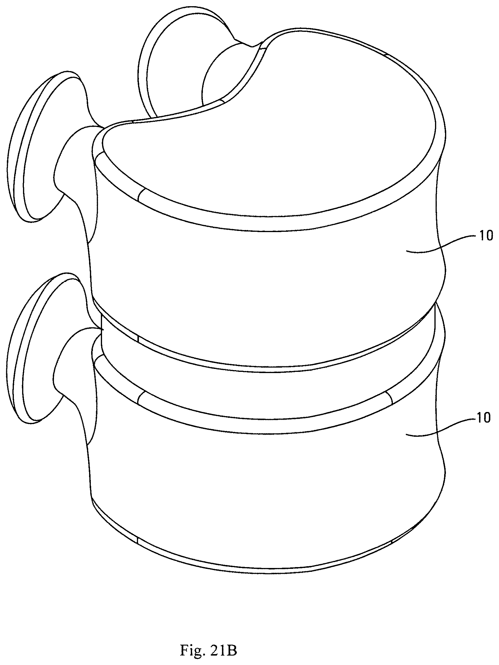
FIGS. 21A-21B are schematic representations of a pair of adjacent vertebral bodies.
While the invention is amenable to various modifications and alternative forms, specifics thereof have been shown by way of example in the drawings and will be described in detail. It should be understood, however, that the intention is not to limit the invention to the particular embodiments described. On the contrary, the intention is to cover all modifications, equivalents, and alternatives falling within the spirit and scope of the invention.
DETAILED DESCRIPTION
In the following detailed description of the present invention, numerous specific details are set forth in order to provide a thorough understanding of the present invention. However, one skilled in the art will recognize that the present invention may be practiced without these specific details. In other instances, well-known methods, procedures, and components have not been described in detail so as to not unnecessarily obscure aspects of the present invention. U.S. Pat. No. 8,628,577, invented by the inventor of the present application, discloses a stable intervertebral body fusion and distraction device. This patent is hereby incorporated herein by reference in its entirety other than the summary of the invention, claims and any express definitions set forth therein.
FIG. 1A is a perspective view of expandable intervertebral cage device 10, as seen from a distal end. FIG. 1B shows the same intervertebral cage device 10 from an opposite, proximal end. As shown in FIGS. 1A and 1B, intervertebral cage device 10 is in a collapsed position. FIG. 1C is a side view of the intervertebral cage device 10 in the collapsed position, and FIG. 1D is a cross-sectional view of the intervertebral cage device 10 taken across the cross-section line 1D-1D shown in FIG. 1A. FIGS. 2A-2D are counterparts to FIGS. 1A-1D showing the same intervertebral cage device 10. However, in FIGS. 2A-2D, while the views of intervertebral cage device 10 are the same as their respective counterparts in FIGS. 1A-1D, device 10 is in a fully expanded configuration rather than the collapsed position. FIGS. 3-9 depict individual elements or parts of device 10 in isolation and in more detail.
Intervertebral cage device 10 includes first base plate 12 and second base plate 14. On each side (i.e., each edge perpendicular to both the base plates 12 and 14 and the proximal/distal axis), intervertebral cage device 10 includes a first arm 16, second arm 18, screw 19, several rings 20, distal block 22, proximal block 24, pins 26, and rods 28. The hidden side of the device 10, not visible in the perspective views herein, comprises many substantially similar structures to those described with reference to the numbered elements. Intervertebral cage device 10 is a device that can be used to hold two structures, such as the vertebrae of a spine, in a fixed spatial relationship with respect to one another. As will be described with respect to subsequent figures, device 10 can be expanded to hold structures in any fixed spatial relationship with a range of distances and angles with respect to one another. Device 10 provides desirable spacing and lordosis and can be operated using a single screw, as described below, to achieve commonly used intervertebral spacing and lordosis levels. In contrast to the multiple-screw devices described above, the user of a single screw device reduces the complexity and increases the mechanical strength of the device. In some embodiments, at full extension the device 10 can exhibit about 23.degree. of lordosis, for example, which is greater than a commonly used angle for many intervertebral devices.
As shown in more detail with respect to FIG. 3, first base plate 12, which is substantially similar to second base plate 14, comprises textured surface 30, arm socket 32, and rod passage 34. First base plate 12 is a portion of device 10 that comprises a bearing surface. As used throughout this disclosure, "bearing surface" refers to the outside surface of a base plate (e.g., 12, 14) that interfaces with the endplate of a vertebra, other bone, or other structures that are to be held in a fixed spatial relationship from one another. Textured surface 30 can comprise, for example, any texture that promotes bone growth to hold the base plate 12, or which provides grip or traction when compressed against bone. Arm socket 32 is usable to provide a mechanical connection between base plate 12 and a corresponding structure, such as first arm 16, as depicted in FIGS. 1A-1D and 2A-2D. Similarly, rod passage 34 can be used to facilitate a mechanical connection between base plate 12 and a corresponding structure, such as proximal block 24, as described in more detail below.
As shown in FIGS. 1A-1D and 2A-2D, base plates 12 and 14 are arranged on opposite from one another in device 10, and can be positioned within a range of distances and angles relative to one another, depending on the extent of the expansion of device 10. For example, as shown with respect to FIGS. 1A-1D, the device 10 is in a collapsed position, and base plates 12 and 14 are relatively close to one another, and arranged substantially parallel to one another. In the configuration shown with respect to FIGS. 2A-2D, the base plates 12 and 14 are relatively further away from one another on the distal end, and are angled relative to one another (this angle is sometimes referred to as lordosis). In embodiments, the extent of lordosis and/or distance between various parts of the base plates 12 and 14 can vary. In some embodiments, base plates can each be angled at 23 degrees. In this embodiment, a proximal end of each base plate can remain at a generally constant distance from each other as the device is expanded about pins 28 (with perhaps a slight change in distance as the plates rotate about pins).
Referring now to FIG. 4, the mechanism by which device 10 is expanded or collapsed is shown, and in particular first arm 16. First arm 16, which is substantially similar to second arm 18, includes body portion 36, first connector 38, and second connector 40. A substantially similar pair of arms to first arm 16 and second arm 18 are included in device 10 on the side that is not depicted in the perspective views previously shown. Body portion 36 extends between first connector 38 and second connector 40. The distance between first connector 38 and second connector 40 determines in part the extent to which the base plates 12 and 14 of FIGS. 2A-2D can be distanced from one another, and the angle between them. First connector 38 and second connector 40 can each be rotatably connected to an adjoining structure. So, for example, as shown with respect to FIGS. 1A-1D and 2A-2D, first connector 38 can be connected to first plate 12 or second plate 14 via a pin 26. Likewise, second connector 40 can be connected to distal block 22. The connections space the parts from one another, while allowing relative rotation between them.
Referring now to FIG. 5, ring 20 is depicted, which can also support interconnection between the base plate 12 and the distal block 22 via any of the arms. In particular, ring 20 holds pin 26 (shown in more detail with respect to FIG. 8) such that it passes through both first base plate 12 and first connector 38 of first arm 16. In operation, the effects of lateral forces (i.e., forces perpendicular to the proximal-distal directions previously described) are mitigated by ring 20. Ring 20 can prevent some types of relative lateral movement between first base plate 12, first arm 16, and pin 26. Ring 20 does this by snapping into groove 52 of pin 26, as described in more detail with respect to FIG. 8.
Referring now to FIG. 6, distal block 22 is shown in perspective. Distal block 22 includes internal passage 42, first bearing 44, and second bearing 46. Internal passage 42 is configured to provide a passage for a portion of screw 19, as shown previously with respect to FIG. 1D and FIG. 2D. In some embodiments, the portion of screw 19 that passes through internal passage 42 is a shank (i.e., unthreaded), or else the internal passage 42 itself is unthreaded, or both, such that there is not co-rotation between distal block 22 and screw 19. Screw 19 passes through internal passage 42 in the embodiment shown in FIGS. 1A-1D and 2A-2D, and as such the distal block 22 and screw 19 are fixed relative to one another in the proximal/distal directions. As described in more detail below with respect to FIG. 7, rotation of screw 19 can cause screw 19 to advance in either the proximal or distal direction, which thereby causes a corresponding movement of the distal block 22 in the same direction. As can be seen in the figures, screw 19 can define a first diameter at proximal block that is greater than a second diameter at distal block. The diameter of screw at the interface with distal block can be the same or greater than that at proximal block to prevent the screw from advancing distally through distal block. A ring 20 can prevent the screw 19 from being pulled proximally through the distal block.
First bearing 44 and second bearing 46 can receive a portion of another object, such as first arm 16 and second arm 18 as shown in FIGS. 1A-1D and 2A-2D. First arm 16 and/or second arm 16 can rotate relative to first bearing 44 and/or second bearing 46, while remaining mechanically fixed to one another. As described above, rotation of screw 19 can cause movement of distal block 22 in the proximal or distal direction. This results in corresponding displacement of the second connector 40 of the first arm 16 (and the corresponding structure in the second arm 18).
FIG. 7 is a perspective depiction of proximal block 24. Proximal block 24 includes internal threads 48 and rod passage 50. Internal threads 48 can be configured to interact with an adjacent component, such as screw 19 as shown in FIGS. 1D and 2D. Proximal block 24 is connected to first base plate 12 and second base plate 14 by rods 28. As shown in FIGS. 1A-1D and 2A-2D, rod 28 connects first base plate 12 with proximal block 24. Rod 28 can pass through rod passages 50 and 34 so that the proximal block 24 is mechanically coupled to first base plate 12 while allowing the base plates (12, 14) to rotate relative to the blocks (22, 24).
FIGS. 8 and 9 depict the connection structures between the first base plate 12 and adjoining structures. In particular, FIG. 8 depicts a pin 26 that connects the first base plate 12 to the distal block 22 via the arms, and FIG. 9 depicts a rod 28 that connects the first base plate 12 to the proximal block 24. Pin 26 further includes groove 52 which can hold ring 20, as previously described.
In operation, first arm 16 and second arm 18 are rotatable and are connected to first base plate 12 and second base plate 14, respectively. Because the structural connection between first base plate 12 and screw 19 is substantially similar to the structural connection between second base plate 14 and screw 19, only the former will be described herein in detail. First base plate 12 is mechanically coupled via pins 26 to first arm 16 via arm socket 32. First arm 16 and second arm 18 are also each mechanically coupled to screw 19 through distal block 22. In all, this connection permits for first base plate 12 to be indirectly connected to the screw 19 while still permitting relative rotation between them. Together with rings 20, distal block 22, proximal block 24, and pins 26, a mechanical interconnection is formed between each of the base plates 12 and 14 that can be adjusted by an external tool (not shown). Rods 28 provide a pivot point that results in a specific relationship between the amount of extension of the device 10 and a relative angle between the first base plate 12 and the second base plate 14.
An external tool (not shown) can be used to turn screw 19, via head 29. Because proximal block 24 is internally threaded (as shown in more detail with respect to FIG. 7), rotation of screw 19 causes relative movement of the screw 19 with respect to the proximal block 24. By contrast, distal block 22 is not internally threaded. Rather, distal block 22 and screw 19 are connected such that movement of screw 19 in either the proximal or distal directions (i.e., the direction in which screw 19 moves relative to proximal block 24 when rotated) causes a corresponding movement of the distal block 22. This can be accomplished as shown, for example, in FIG. 2D, where distal block 22 is pushed and/or pulled by screw 19, and the interconnection is made by a spring or clamp on one side holding the distal block 22 against a flange on the screw 19. In alternative embodiments, various other interconnections between the screw and block can be made, which will result in co-movement in the proximal or distal direction without co-rotation. As distal block 22 is moved by screw 19, it forces movement of first arm 16 and second arm 18.
As screw 19 is rotated, due to the internal threading of proximal block 24, the distance between the distal block 22 and proximal block 24 changes. As the distance between distal block 22 and proximal block 24 increases, the arms 16 and 18 are caused to rotate. First arm 16 and second arm 18 rotate as the device 10 is converted from a collapsed configuration, such as that shown in FIGS. 1A-1D, to an expanded configuration, such as that shown with respect to FIGS. 2A-2D. This rotation results in increased distance between the first base plate 12 and the second base plate 14, as well as increased lordosis. As described with respect to other embodiments below, rotating screw 19 to change the distance between first base plate 12 and second base plate 14, as well as changing the amount of lordosis, can be useful to provide intervertebral support.
The embodiment shown in FIGS. 1A-1D, 2A-2D, and 3-9 provides such intervertebral spacing, support, and lordosis with a relatively straightforward mechanical structure. The device 10 can be implanted in a compact configuration, then expanded to the appropriate size and angle by rotating screw 19, causing the changes in angle and spacing previously described, as desired.
Referring to FIGS. 10A-10C and FIG. 11, there can be seen an expandable intervertebral cage device 100 according to an aspect of the present invention. Device 100 includes a device body 102. Device body 102 can include a nose portion 104, a rear portion 106, a pair of opposed base plates 108 having outer bearing surfaces 107, and a plurality of arm assemblies 110. Schematic representations of a pair of adjacent vertebral bodies 10 are depicted in FIGS. 21A-21B. Each arm assembly 110 can include a pair of opposed arms 112 hingedly attached to each other, with each opposing arm 112 hingedly attached to one of the base plates 108. In one embodiment, device 100 can include three arm assemblies 110a, 110b, and 110c, extending crosswise from first side 116 of device 100 to second side 118 of device 100. In one embodiment, opposing arms 112 of arm assemblies 110a, 110b, and 110c are pivotally coupled to a blocks 122a, 122b, and 122c with pins 114. Block 122a can be positioned nearest the rear portion 106, block 122c can be positioned nearest the nose portion 104, and block 122b can be positioned between blocks 122a and 122c.
Referring to FIGS. 12A-12C, in one embodiment, base plates 108 can include a first, or top, base plate 108a, with a top bearing surface 107a configured to interface with an end plate of a superior vertebra of the intervertebral disc space, and a second, or bottom, base plate 108b having a bottom bearing surface 107b configured to interface with an end plate of an inferior vertebra of the intervertebral disc space. In one embodiment, each base plate 108 can include one or more openings 124 to facilitate bone growth through the device 100. Openings 124 promote vertebral fusion because bone can grow directly through the device 100. Although depicted as being generally rectangular, opening 124 can comprise any shape. Alternatively, a generally solid surface or a surface with multiple openings can be provided on each base plate 108.
Base plates 108 can have a rough surface or teeth 109 to create friction with the base plates of the vertebra to prevent accidental extrusion of the device 100 or to promote bone growth for successful fusion. Base plates 108 or other elements of the device can also in some embodiments be made compliant for exaggerated non-uniform distraction while maintaining the stability of the device 100. Nose portion 104 can be tapered to facilitate insertion of the device 100 into the disc space. Rear portion 106 can also be tapered. In one embodiment, base plate 108 can include a plurality of bores 105. Each bore 105 can be sized to accept a portion of opposing arm 112 to facilitate a hinged coupling.
In one embodiment, device 100 can have a total of twelve arms 112 (four arms for each arm assembly 110a, 110b, and 110c, with two arms of each assembly on each side of the device). In one embodiment, all of the arms 112 can be substantially identical. Referring to FIG. 13, each arm 112 can include a protrusion 113 sized to fit into one of the bores 105 of base plate 108 to facilitate a hinged coupling. In one embodiment, arms 112 can be welded to base plates to prevent failure. Each arm 112 can include a bore 115 sized to accept a pin 114 for coupling the arm 112 to a block 122.
In one embodiment, device can have a total of three blocks--a first or proximal block 122a, a second or central block 122b and a third or distal block 122c. Referring to FIG. 14, in one embodiment, central and distal blocks 122b and 122c can be substantially identical. Each block 122 can be defined by two side bores 128 sized to accept pin 114 for the purpose of coupling two arms 112 to block 122. In one embodiment, side bores 128 can be substantially parallel to one another. Each block 122 can also be defined by two longitudinal bores 126, each sized to accept an actuation member 120. In one embodiment, each longitudinal bore 126 can be threaded. In another embodiment, only one longitudinal bore 126 of each block 122 is threaded. In one embodiment, longitudinal bores 126 can be substantially parallel to one another. In one embodiment, longitudinal bores 126 can be orthogonal to side bores 128. Proximal block 122a can be adapted to attach to an insertion device for inserting device 100 into the disc space. In one embodiment, side slots 125 of proximal block 122a can be configured to receive portions of insertion device.
In one embodiment, device 100 can include a total of six pins 114. Referring to FIG. 15, each pin 114 can be substantially cylindrical in shape and have opposing ends 127 sized to fit into bore 115 of arms 112 on opposing sides 116, 118 of device 100. Pins can be sized to extend through side bore 128 of block 122 between opposing arms 112, for the purpose of pivotably coupling two arms 112 to a given block 122. In one embodiment, pin 114 can include notches 129. Notches 129 can be sized to allow clearance for actuation members 120 through longitudinal bores 126, thereby allowing each arm assembly 110 to be more compact. In one embodiment, pin 114 can include a slot 131 proximate each end 127 of pin 114 sized to accept a snap ring 133 (shown in FIG. 16) that sits outside of arms to lock pins in place. In one embodiment, a distal portion of one or more actuation members 120 can have a larger diameter than the remainder of actuation member. Longitudinal bores 126 would therefore be larger to accommodate this larger section of the screw.
Referring to FIG. 16, in one embodiment, device 100 can include a first actuation member 120a and a second actuation member 120b. In one embodiment, actuation members 120a and 120b can be substantially identical. In one embodiment, actuation member 120 can include a threaded portion 135 of a diameter sized to threadedly couple with longitudinal bore 126 of one or more blocks 122. Actuation member 120 can include a second non-threaded portion 136 having a smaller diameter than threaded portion 135. One end of actuation member 120 can be defined by a slot or socket 138 structured to receive a tool for driving actuation device 120. In one embodiment, socket 138 can be capable of receiving a hex key or Allen wrench, for example, for rotatably driving actuation device 120. In one embodiment, actuation member 120 can include a slot 137 proximate one end of actuation member 120 sized to accept snap ring 139 that can lock actuation members in axial position relative to blocks. Alternatively, snap ring 139 can be located at the proximal end of block 122c, which provides further stability to the screw and reduces the stress on the snap ring.
In one embodiment, first actuation member 120a can extend through first arm assembly 110a into second arm assembly 110a. For example, first actuation member 120a can be threadedly coupled to first arm assembly 110a and rotationally coupled to second arm assembly 110b. Second actuation member 120b can extend through second arm assembly 110a into third arm assembly 110c. For example, second actuation member 120a can be threadedly coupled to second arm assembly 110b and rotationally coupled to third arm assembly 110c.
As shown in FIGS. 17A-17B, in one embodiment, actuation of first actuation member 120a in a first direction drives blocks 122a and 122b closer together, which causes expansion of arm assemblies 110a and 110b and distraction of base plates 108. As shown in FIGS. 17A-17B, actuation of second actuation member 120b in a first direction drives blocks 122b and 122c closer together, which causes expansion of arm assemblies 110a and 110b and distraction of base plates 108.
First actuation member 120a and second actuation member 120b are capable of being actuated independently of each other. This independent actuation allows for angular orientation of the base plates 108 to be matched exactly to the unique alignment, or desired planar alignment, of adjacent vertebrae of a patient's spine. Examples of various possible angular orientations of base plates 108 in the distracted state can be seen at FIGS. 17A-17B. Such angulations can be done when the device is expanded within the disc space, enabling the device to go between lordotic and kyphotic angles while in the disc space so that the surgeon can adjust as needed to correct the deformity based on observations made during the procedure.
Conversely, actuation of first actuation member 120a in the opposite direction drives blocks 122a and 122b apart, thereby bringing base plates 108 closer together. Likewise, actuation of second actuation member 120b in the opposite direction drives blocks 122b and 122c apart, thereby bringing base plates 108 closer together. This back-drivability of the device 100 is helpful for sizing the device 100 and removing the device 100 if necessary, such as in the event of post-surgical infection, trauma, or failure to fuse.
Referring again to FIG. 16, non-threaded portion 136 of actuation member 120 and its respective rotational coupling to block 122 enable device 100 to allow for additional distraction due to in-vivo axial tension. For example, the rotational coupling can be constructed with sufficient clearance to allow block 122b to temporarily slide closer to 122a, or block 122c to temporarily slide closer to block 122b. However, having distracted slightly under tensile loading the device would return to the original height as compressive loading is returned. The parallelism would remain unchanged, while lordotic endplates may undergo a small angular displacement that would return to the set lordosis with the reapplication of the normal compressive loading. This extensibility of device 100 could offer great benefits to the fusion process as the endplates, which may be growing into the endplates of the vertebral bodies, would not be pulled away from the endplates by motion of the patient's spine, damaging early bone growth.
In another embodiment, in place of non-threaded portion 136 and snap ring 139, portions of the actuation member 120 can be reverse threaded to allow distraction without changing the position of the threaded members along the respective axes of the threaded members helping to keep the device from adversely interacting with the anatomy of the patient.
In various embodiments, device body 102 is shaped to be ergonomic. Device body 102 can have various shapes, such as, for example, rectangular or kidney-shaped. A kidney-shaped device body 102 maximizes contact between the device and the vertebral bodies because the base plates of vertebrae tend to be slightly concave. One or both ends of the device may also be tapered to facilitate insertion. This minimizes the amount of force needed to initially separate the vertebral bodies. In addition, the device may be convex along both its length and its width, or bi-convex. Device body can also be comprised of various materials. Such materials can include, for example, titanium, steel, PEEK, carbon fiber and cobalt chromium. The device can also be constructed in various sizes depending on the type of vertebra and size of patient with which it is being used, for example, specifically for an anterior lumbar interbody fusion, oblique or a laterlal interbody fusion. In some embodiments, the threaded member 120 can be micro-machined or split along its length and reconnected using a bellows or flexible torque transmission device, to be able to operate through an angle that may be necessitated by the shape of the device.
In one embodiment, a locking mechanism can be utilized to prevent rotation of the threaded members to ensure the device remains in the distracted state. In one embodiment, the locking mechanism can be activated with the insertion device. In one embodiment, locking may be enhanced by tightening a threaded nut (not shown) against one or more of the blocks 122.
As is demonstrated by a simplified form of device 100 shown in FIG. 20, device 100 can stably support the disc space because it has negative one degree of freedom once locked in the distracted position with actuation members 120 in place. From Gruebler's equation, the number of degrees of freedom=3*(n-1)-2f, where n is the number of links in the linkage and f is the number of one degree of freedom kinematic pairs in the linkage. As is shown in FIG. 20, the device 100 has 10 links and 14 kinematic pairs, so 3*(10-1)-2*14=-1 degrees of freedom. The device is therefore actually over constrained (meaning that there are additional constraints beyond the minimum necessary to make it stable), and stable under loading conditions. This allows device 100 to stably support the disc space upon distraction. In some embodiments, a crush surface or compliant materials may be used in concert with structure to minimize hysteresis that may be present in the device and due to clearance in arm assemblies 112 necessary for overcoming the over-constraint in devices having fewer than zero degrees of freedom due to redundant constraints.
In operation, device 100 can be placed between adjacent vertebrae or vertebral bodies and used to distract the endplates of the adjacent vertebral bodies and subsequently serve as a fusion device. One or more insertion tools (not depicted) can be used to insert and distract device 100. Referring to FIGS. 10A, 10B and 11, the device body 102 can be seen in its initial compressed configuration. In FIGS. 17A-19B, device body 102 is in various expanded configurations. The insertion tool can be connected to actuation members 120 with the proximal block 122a and first used to insert device 100 into a desired location. Device 100 can be inserted with tapered nose portion 104 first. One device 100 can be inserted, or, for additional support, two devices 100 can be inserted. Two devices 100, each sized to be inserted within one-half of the evacuated disc space, can be especially useful for treating larger patients in which the device may encounter higher loads. In another embodiment, three or more small devices can be inserted into the disc space in order to very accurately control the orientation and distance between the discs. Three or more distraction mechanisms may be positioned circumferentially between two circular endplates to result in very accurate control and orientation of the base plates. Such a device would resemble a hexapod.
To distract device 100, an insertion tool can be used to rotate actuation members 120 in a first direction. Actuation of threaded member 120a in a first direction drives blocks 122a and 122b closer together, which causes distraction of base plates 108. Likewise, actuation of threaded member 120b in a first direction drives blocks 122b and 122c closer together, which causes distraction of base plates 108. Actuation of threaded members 120a and 120b in the opposite direction respectively drives blocks 122a and 122b and blocks 122b and 122c apart, thereby bringing base plates 108 closer together.
Once base plates 108 are distracted to a desired degree, insertion tools can be disconnected from threaded members 120 and the device 100 can remain within the body. In one embodiment, a locking mechanism can be utilized to prevent rotation of the threaded members to ensure the device remains in the distracted state.
Once device is inserted and supporting the adjacent vertebral bodies, it can be utilized to promote vertebral fusion. Following distraction, a bone growth stimulant, such as autograft, bone morphogenic protein, or bone enhancing material, can be delivered into an open area defined within the device. In one embodiment, bone growth stimulant is delivered after insertion tools are disconnected. In another embodiment, bone growth stimulant is delivered through an open area between insertion tools. In a further embodiment, bone growth stimulant can be delivered through a hollow chamber within the insertion tools. Device is capable of supporting in-vivo loads during the 6 to 12 weeks that fusion occurs between the vertebral bodies. In one embodiment, openings 124 in base plates 108 promote and allow for bone growth into and through the device 100.
In some embodiments, when the device is implanted and in the process of being expanded, as blocks come closer together the blocks compress the bone graft or bone fusion material that can be inserted inside device to force the material out of the internal chamber of the device an in the adjacent vertebral end plates. This will enhance bone integration into the end plates. Some bone material will remain within the cage, which will integrate and fuse the center of the cage to the top and bottom of the end plates. In certain embodiments, the bone material can be injected into the device through one of the longitudinal holes in the proximal block of the device that does not have an actuation member therethrough. This could be done with the inserter device or separate extended syringe. In some embodiments, the top and bottom base plates of the device can be coated to enhance bone integration.
In an alternative embodiment, a pin can extend vertical through the device to stabilize the proximal end of the device. Such a device could be expanded utilizing only a distal set of arm assemblies and would provide only lordotic angles. Alternatively the pin could stabilize the distal end of the device, which could then be expanded with a single screw and one or more proximally located arm assemblies to provide kyphotic angles.
Although the various devices described herein are described as being brought from a compressed configuration to an expanded configuration by rotation of a threaded member, the devices can be distracted by any other type of actuation member. In some embodiments, mechanisms other than threaded members can be used to distract the device. Such mechanisms include, for example, a pop-rivet mechanism, a sardine key and ribbon, a tourniquet and wire, a saw blade/ratchet, a zip-tie-like mechanism, piezo-electric inch worm motors and shape changing materials such as a shape member alloy or a conducting polymer actuator. These alternative locking mechanisms could be designed to make the device behave as if it were locked with a threaded member, preventing the device from being compressed as well as extended, or these mechanisms could afford the device the capability to ratchet upwards post implantation if such action would benefit the patient or provide additional therapy.
Various embodiments of implantation procedures for the disclosed embodiments of expandable intervertebral cage devices may be as follows:
Lumbar: A lumbar implant can be 8 mm in height, expandable to 14 mm in height, with a length of 25-30 mm and a width of 10-12 mm. The implant can be inserted through a minimally invasive tubular port that goes through the muscle of the lumbar spine and into the lumbar disc space. Prior to inserting the implant, the lumbar disc should be completely removed. Other embodiments for the lumbar spine include larger sizes for anterior, posterior, transforaminal, oblique lateral, and lateral interbody fusions.
Cervical: A cervical implant can be 6 mm in height, expandable to 10 mm in height, with a length of 10 mm and a width of 6 mm. The implant can be inserted after anterior cervical surgical exposure. The cervical disc should be completely removed prior to insertion of the implant.
Various embodiments of systems, devices, and methods have been described herein. These embodiments are given only by way of example and are not intended to limit the scope of the present invention. It should be appreciated, moreover, that the various features of the embodiments that have been described may be combined in various ways to produce numerous additional embodiments. Moreover, while various materials, dimensions, shapes, implantation locations, etc. have been described for use with disclosed embodiments, others besides those disclosed may be utilized without exceeding the scope of the invention.
* * * * *
References
D00000
D00001
D00002
D00003
D00004
D00005
D00006
D00007
D00008
D00009
D00010
D00011
D00012

D00013
D00014
D00015
D00016

D00017

D00018
XML
uspto.report is an independent third-party trademark research tool that is not affiliated, endorsed, or sponsored by the United States Patent and Trademark Office (USPTO) or any other governmental organization. The information provided by uspto.report is based on publicly available data at the time of writing and is intended for informational purposes only.
While we strive to provide accurate and up-to-date information, we do not guarantee the accuracy, completeness, reliability, or suitability of the information displayed on this site. The use of this site is at your own risk. Any reliance you place on such information is therefore strictly at your own risk.
All official trademark data, including owner information, should be verified by visiting the official USPTO website at www.uspto.gov. This site is not intended to replace professional legal advice and should not be used as a substitute for consulting with a legal professional who is knowledgeable about trademark law.