Battery with aluminum-containing cathode
Angell , et al.
U.S. patent number 10,686,224 [Application Number 15/956,630] was granted by the patent office on 2020-06-16 for battery with aluminum-containing cathode. This patent grant is currently assigned to Arizona Board of Regents on behalf of Arizona State University. The grantee listed for this patent is C. Austen Angell, Leigang Xue. Invention is credited to C. Austen Angell, Leigang Xue.


| United States Patent | 10,686,224 |
| Angell , et al. | June 16, 2020 |
Battery with aluminum-containing cathode
Abstract
A battery includes an anode chamber configured to contain an anolyte and including an anode, a cathode chamber configured to contain a catholyte including a cathode, and a separator between the anode chamber and the cathode chamber. The anode includes sodium, and the cathode includes aluminum. The battery is configured to be operated above a melting point of the anolyte and the catholyte, such that the anolyte is a molten anolyte and the catholyte is a molten catholyte.
| Inventors: | Angell; C. Austen (Mesa, AZ), Xue; Leigang (Austin, TX) | ||||||||||
|---|---|---|---|---|---|---|---|---|---|---|---|
| Applicant: |
|
||||||||||
| Assignee: | Arizona Board of Regents on behalf
of Arizona State University (Scottsdale, AZ) |
||||||||||
| Family ID: | 63854650 | ||||||||||
| Appl. No.: | 15/956,630 | ||||||||||
| Filed: | April 18, 2018 |
Prior Publication Data
| Document Identifier | Publication Date | |
|---|---|---|
| US 20180309170 A1 | Oct 25, 2018 | |
Related U.S. Patent Documents
| Application Number | Filing Date | Patent Number | Issue Date | ||
|---|---|---|---|---|---|
| 62487406 | Apr 19, 2017 | ||||
| Current U.S. Class: | 1/1 |
| Current CPC Class: | H01M 10/399 (20130101); H01M 2/1686 (20130101); H01M 2/1646 (20130101); H01M 4/381 (20130101); H01M 2300/0057 (20130101) |
| Current International Class: | H01M 10/39 (20060101); H01M 2/16 (20060101); H01M 4/38 (20060101) |
References Cited [Referenced By]
U.S. Patent Documents
| 5484670 | January 1996 | Angell et al. |
| 5506073 | April 1996 | Angell et al. |
| 5786110 | July 1998 | Angell et al. |
| 5824433 | October 1998 | Angell et al. |
| 5849432 | December 1998 | Angell et al. |
| 5855809 | January 1999 | Angell et al. |
| 5962169 | October 1999 | Angell et al. |
| 6245465 | June 2001 | Angell et al. |
| 7012124 | March 2006 | Angell et al. |
| 7504473 | March 2009 | Angell et al. |
| 7527899 | May 2009 | Angell et al. |
| 7833643 | November 2010 | Angell et al. |
| 7833666 | November 2010 | Angell et al. |
| 7867658 | January 2011 | Angell et al. |
| 8273477 | September 2012 | Angell et al. |
| 9647288 | May 2017 | Angell et al. |
| 9768462 | September 2017 | Angell et al. |
| 2006/0189776 | August 2006 | Angell et al. |
| 2008/0226989 | September 2008 | Angell et al. |
| 2009/0226817 | September 2009 | Angell et al. |
| 2011/0020712 | January 2011 | Angell et al. |
| 2011/0143212 | June 2011 | Angell et al. |
| 2015/0318586 | November 2015 | Rahmane |
| 2016/0043431 | February 2016 | Angell et al. |
| 2016/0308253 | October 2016 | Robins |
| 2017/0309943 | October 2017 | Angell |
| 2019/0020060 | January 2019 | Angell et al. |
| 2098870 | Dec 1993 | CA | |||
| 0576225 | Dec 1998 | EP | |||
| 183199 | Nov 1996 | MX | |||
| 1996039725 | Dec 1996 | WO | |||
| 1997016862 | May 1997 | WO | |||
| 1997018159 | May 1997 | WO | |||
| 1997018595 | May 1997 | WO | |||
| 1999019932 | Apr 1999 | WO | |||
| 2001096446 | Dec 2001 | WO | |||
| 2001098396 | Dec 2001 | WO | |||
| 2001099209 | Dec 2001 | WO | |||
| 2004114445 | Dec 2004 | WO | |||
| 2006078866 | Jul 2006 | WO | |||
| 2008118210 | Oct 2008 | WO | |||
| 2009042958 | Apr 2009 | WO | |||
| 2014028894 | Feb 2014 | WO | |||
| 2014153146 | Sep 2014 | WO | |||
| 2016044324 | Mar 2016 | WO | |||
Other References
|
Benato et al, "Sodium Nickel Chloride Battery Technology for Large-Scale Stationary Storage in the High Voltage Network," Journal of Power Sources. 293, pp. 127-136, Oct. 20, 2015. cited by applicant . Berg et al, "Phase-Diagram of the NaCl--AlCl3 System Near Equimolar Composition, With Determination of the Cryoscopic Constant, the Enthalpy of Melting, and Oxide Contaminations," Inorganic Chemistry, 23, 5, pp. 557-565, 1984. cited by applicant . Bones et al, "Development of a Ni,NiCl2 Positive Electrode for a Liquid Sodium (ZEBRA) Battery Cell," J. Electrochem. Soc., 136, 5, pp. 1274-1277, May 1989. cited by applicant . Dewing, "Thermodynamics of the System NaCl--AlCl3," Metallurgical Transactions B-Process Metallurgy 12, 4, pp. 105-719, Dec. 1981. cited by applicant . Dustmann, "Advances in ZEBRA batteries," Journal of Power Sources, 127, 1, pp. 85-92, Mar. 2004. cited by applicant . Ellis et al, "Sodium and Sodium-Ion Energy Storage Batteries," Current Opinion in Solid State and Materials Science, 16, 4, pp. 168-177, Aug. 2012. cited by applicant . Li et al, "Liquid Metal Electrodes for Energy Storage Batteries," Advanced Energy Materials, 2016, 6, pp. 1-19, May 2016. cited by applicant . Lu et al, "Liquid-metal electrode to enable ultra-lowtemperature sodium-beta alumina batteries for renewable energy storage," Nature Communications, 5, 8, pp. 1-8, Aug. 2014. cited by applicant . Mohandas et al, "An Electrochemical Investigation of the Thermodynamic Properties of the NaCl--AlCl3 System at SubliquidusTemperatures," Metallurgical and Materials Transactions B, 32, 4, pp. 669-677 Aug. 2001. cited by applicant . Tucker et al, "Approaches to, and Problems with, Ionic Liquid Electrolytes for Alkali Metal Electrochemical Devices: The Case ofLow-Melting Chloroaluminate Binary Solutions," J. Electrochem Soc., 161, 12, pp. H796-H801, Sep. 4, 2014. cited by applicant . Wang et al, "Lithium-antimony-lead liquid metal battery forgrid-level energy storage," Nature 514, pp. 348-350, Oct. 16, 2014. cited by applicant . Xue et al, "Ionic Liquid Redox Catholyte for High Energy Efficiency,Low-Cost Energy Storage," Advanced Energy Materials, 5, 12, pp. 1-8, Apr. 17, 2015. cited by applicant. |
Primary Examiner: Fraser; Stewart A
Attorney, Agent or Firm: Fish & Richardson P.C.
Government Interests
STATEMENT OF GOVERNMENT INTEREST
This invention was made with government support under 1111357 awarded by the Department of Energy. The government has certain rights in the invention.
Parent Case Text
CROSS-REFERENCE TO RELATED APPLICATION
This application claims the benefit of U.S. Patent Application No. 62/487,406 entitled "BATTERY WITH ALUMINUM CATHODE" and filed on Apr. 19, 2017, which is incorporated by reference herein in its entirety.
Claims
What is claimed is:
1. A battery comprising: an anode chamber comprising an anode, wherein the anode comprises sodium; a cathode chamber comprising a cathode, wherein the cathode comprises aluminum; and a separator between the anode chamber and the cathode chamber, wherein: the anode chamber contains an anolyte, the cathode chamber contains a catholyte, wherein the catholyte comprises a 4:1 molar ratio of NaAl.sub.2Cl.sub.7 and 1-ethyl-3-methylimidazolium chloride (EMIAlCl.sub.4), and the battery is configured to be operated above a melting point of the anolyte and the catholyte, such that the anolyte is a molten anolyte and the catholyte is a molten catholyte.
2. The battery of claim 1, wherein the anolyte comprises sodium.
3. The battery of claim 1, wherein the separator comprises a solid sodium super ion conductor.
4. The battery of claim 3, wherein the solid sodium ion conductor comprises a porous coating of an electronically conductive metal oxide proximate the anode chamber.
5. The battery of claim 4, wherein the electronically conductive metal oxide comprises indium tin oxide.
6. The battery of claim 1, wherein the cathode chamber comprises aluminum wool in direct contact with the separator, and the catholyte is in direct contact with the aluminum wool and the separator.
7. The battery of claim 1, wherein charging the battery results in the formation of sodium.
8. The battery of claim 1, wherein discharging the battery results in the formation of aluminum.
9. The battery of claim 1, wherein the anode comprises molten sodium.
10. The battery of claim 1, wherein the cathode comprises molten NaAl.sub.2Cl.sub.7.
11. A battery comprising: an anode chamber comprising an anode, wherein the anode comprises sodium; a cathode chamber comprising a cathode, wherein the cathode comprises aluminum; and a separator between the anode chamber and the cathode chamber, wherein: the anode chamber contains an anolyte, the cathode chamber contains a catholyte, wherein the catholyte comprises a 4:1 molar ratio of Na.sub.2Al.sub.2Cl.sub.7 and 1-ethyl-3-methylimidazolium chloride (EMIAlCl.sub.4), the cathode chamber comprises aluminum wool in direct contact with the separator, and the catholyte is in direct contact with the aluminum wool and the separator, and the battery is configured to be operated above a melting point of the anolyte and the catholyte, such that the anolyte is a molten anolyte and the catholyte is a molten catholyte.
Description
TECHNICAL FIELD
This disclosure relates to batteries having an aluminum-containing cathode.
BACKGROUND
When a cathode including aluminum is used in a battery with an aqueous electrolyte, hydroxide and oxide anions generated at the anode can react with the aluminum to form a passivating aluminum oxide layer. In some cases, an electric field can draw anions through an aluminum oxide layer on the cathode, growing the oxide layer into as well as away from the surface of an electrode. Thus, the use of aluminum in cathodes can be hindered by the inability of cathodes to provide reversible insertion of aluminum ions.
SUMMARY
In a first general aspect, a battery includes an anode chamber configured to contain an anolyte and including an anode, a cathode chamber configured to contain a catholyte including a cathode, and a separator between the anode chamber and the cathode chamber. The anode includes sodium, and the cathode includes aluminum. The battery is configured to be operated above a melting point of the anolyte and the catholyte, such that the anolyte is a molten anolyte and the catholyte is a molten catholyte.
Implementations of the first general aspect may include one or more of the following features.
The anode may consist of sodium or consist essentially of sodium. The anolyte includes sodium, consists of sodium, or consists essentially of sodium. During operation of the battery, the anode and the anolyte may both be molten sodium.
In some cases, the cathode includes NaAl.sub.2Cl.sub.7. The catholyte typically includes NaAl.sub.2Cl.sub.7. The catholyte may include AlCl.sub.3. In some cases, the catholyte includes EMIAlCl.sub.4, where EMIAlCl.sub.4 is a compound of 1-ethyl-3-methylimidazolium chloride and AlCl.sub.3.
The separator includes a solid sodium super ionic conductor. In some cases, the solid sodium ion conductor includes a porous coating of an electronically conductive metal oxide (e.g., indium tin oxide) proximate the anode chamber.
The cathode chamber may include aluminum wool. The aluminum wool is in direct contact with the separator, and the catholyte is in direct contact with the aluminum wool and the separator.
Charging the battery typically results in the formation of sodium, and discharging the battery typically results in the formation of aluminum.
BRIEF DESCRIPTION OF THE DRAWINGS
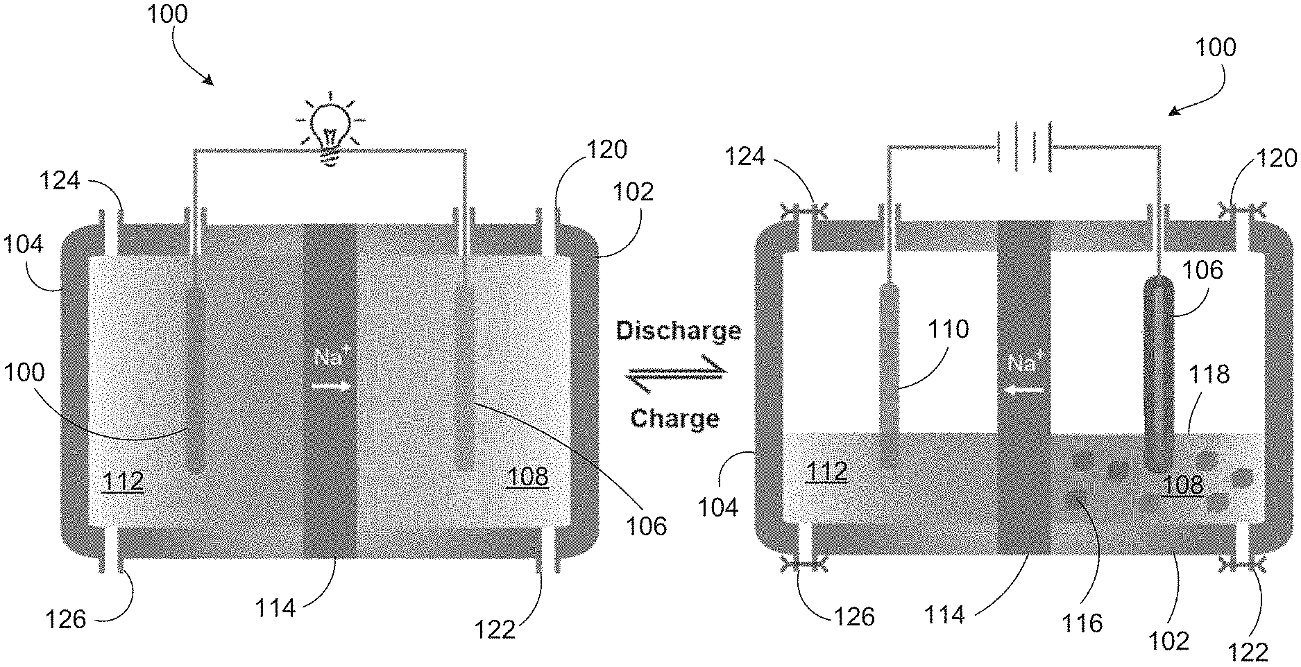
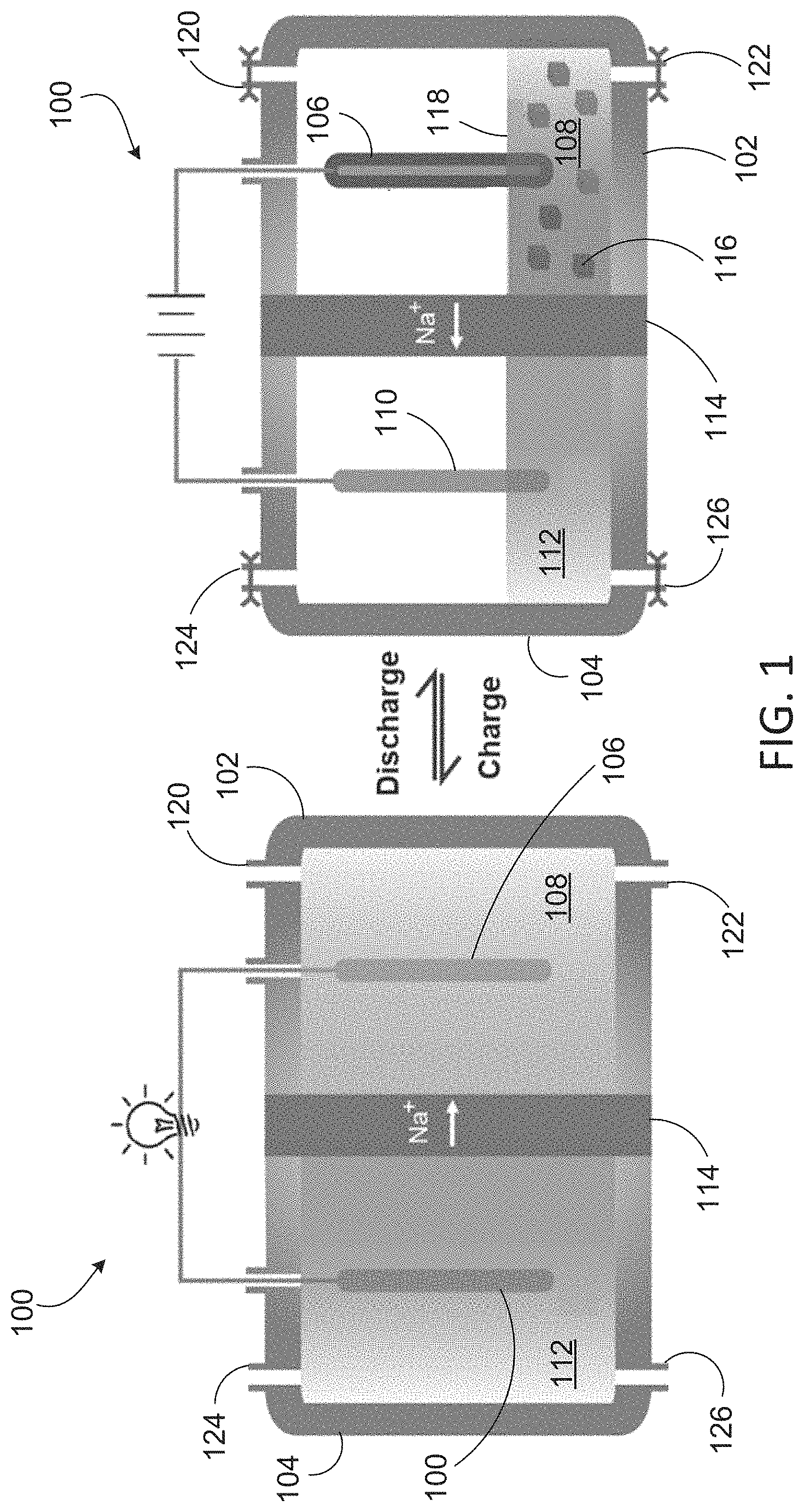
FIG. 1 depicts charging and discharging of a Na--Al battery with an aluminum cathode.
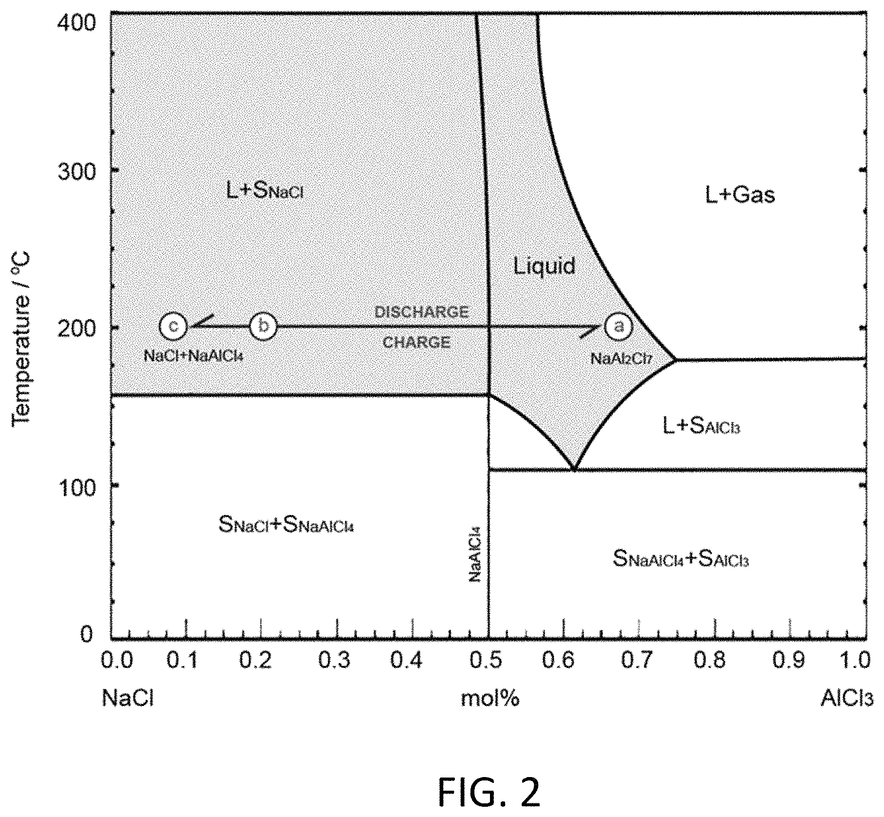
FIG. 2 depicts a NaCl--AlCl.sub.3 phase diagram.
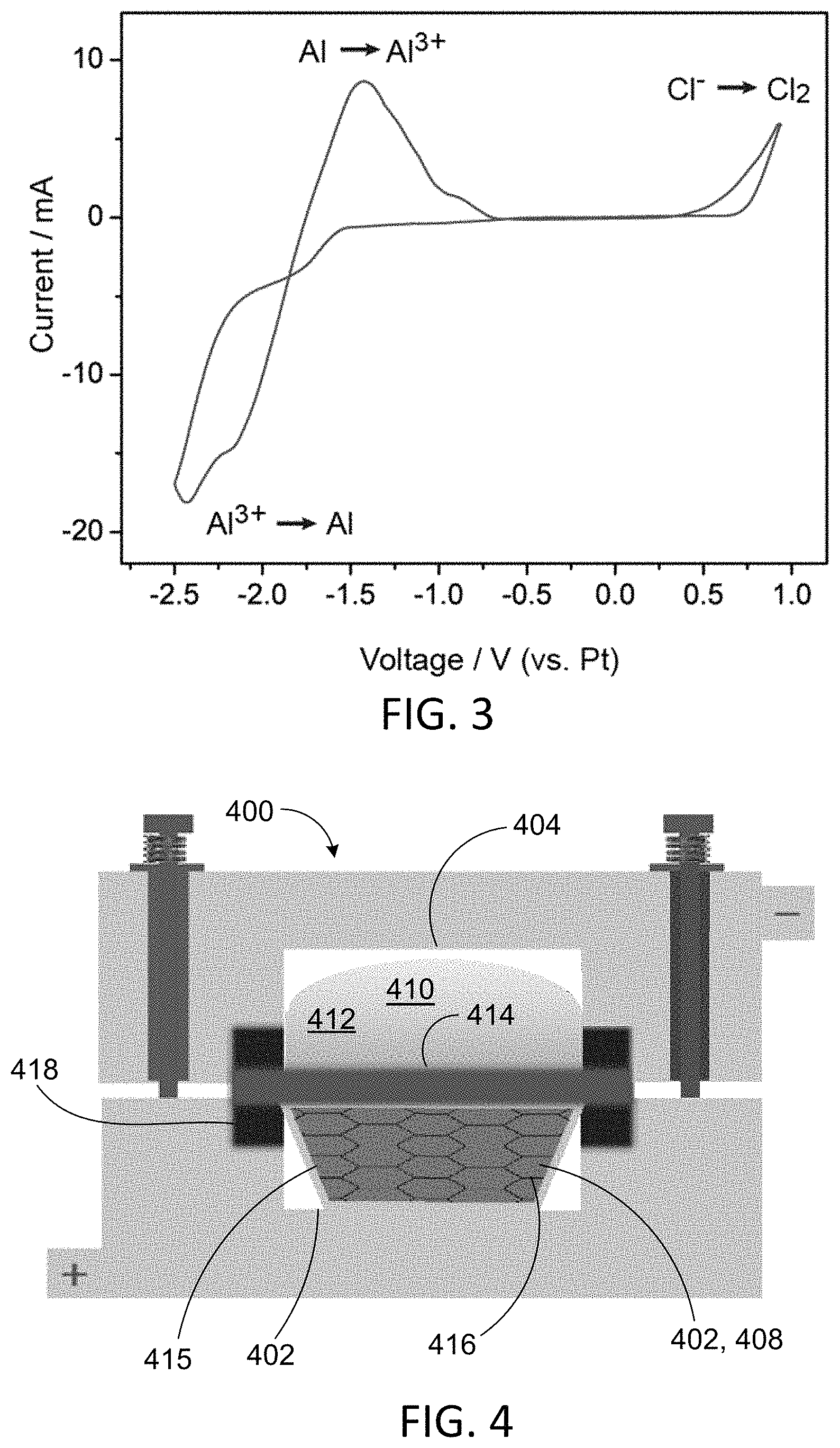
FIG. 3 shows cyclic voltammograms of NaAl.sub.2Cl.sub.7 catholyte.
FIG. 4 depicts a battery with an aluminum-containing cathode.
FIG. 5A shows discharge and charge curves of a Na--Al battery at 0.1 C with NaAl.sub.2Cl.sub.7 catholyte. FIG. 5B shows discharge and charge curves of a Na--Al battery at 0.2 C with NaAl.sub.2Cl.sub.7-EMIAlCl.sub.4 (4:1 mole ratio) catholyte.
FIG. 6 shows specific conductivities of NaAl.sub.2Cl.sub.7, EMIAlCl.sub.4 and their mixtures.
DETAILED DESCRIPTION
FIG. 1 depicts charging and discharging of a sodium (Na)-aluminum (Al) battery with an aluminum-containing cathode. Battery 100 includes cathode chamber 102 and anode chamber 104. Cathode chamber 102 includes cathode 106 and catholyte 108. Anode chamber 104 includes anode 110 and anolyte 112. Cathode 102 includes aluminum. In one example, cathode 102 and catholyte 108 include NaAl.sub.2Cl.sub.7, and anode 106 and anolyte 112 include molten sodium. In some cases (e.g., during discharge), at least one of cathode 102 and catholyte 108 includes NaAl.sub.2Cl.sub.7 and NaAlCl.sub.4. Cathode chamber 102 and anode chamber 104 are separated by solid sodium ion conductor 114. In one example, sodium ion conductor 114 is a sodium super ionic conductor (NaSICON), which typically refers to a family of solids with the chemical formula Na.sub.1+xZr.sub.2Si.sub.xP.sub.3-xO.sub.12, 0<x<3.
Non-aqueous media such as ionic liquids and molten salts can be free of oxygen, such that cathode 106 in battery 100 does not form a surface oxide film during operation. Aluminum has relatively low electropositivity compared to alkali metal anodes. For an aluminum-containing material to be suitable as a cathode, it should be capable of supporting reversible plating and stripping of aluminum metal, and a compatible electrolyte is needed to support alkali ion migration to and from anode chamber 102 to maintain charge balance. NaAl.sub.2Cl.sub.7 (mole ratio of AlCl.sub.3:NaCl=2:1), a combination of AlCl.sub.3 and NaCl, may be used as catholyte 108. In one example, catholyte 108 is NaAl.sub.2Cl.sub.7 and anolyte 112 is molten sodium. At least one of NaAlCl.sub.4 and NaCl may be present in catholyte as solids 116 and 118, respectively. In the charged state, both the catholyte and the anolyte are liquid. During the discharge, the liquid volume of anolyte 112 and catholyte 108 decreases, as solid NaCl and Al metal are produced. In the recharge process, solid NaCl and Al metal return to the molten sodium and molten NaAl.sub.2Cl.sub.7 respectively. Battery 100 may be recharged with fresh catholyte 108 and fresh anolyte 112 via inlet and outlet valves 120, 122 and 124, 126, respectively.
The voltage output of a Na--Al battery such as that depicted in FIG. 1 was found to be 1.55 V in a molten salt medium. This is close to, but smaller than, the value calculated from the standard free energy change for the process 3Na+AlCl.sub.3=3NaCl+Al of 1.80 V at 25.degree. C. The battery can be operated at 200.degree. C. to overcome ceramic separator kinetics and to keep sodium and NaAl.sub.2Cl.sub.7 in the molten state. The sodium anolyte and NaAl.sub.2Cl.sub.7 catholyte together showed a high energy density of 366 Whkg.sup.-1, with a voltage of about 1.55 V. The high energy density, low-cost and internal safety make this chemistry applicable to the large scale energy storage market.
According to the NaCl--AlCl.sub.3 phase diagram depicted in FIG. 2, NaCl and AlCl.sub.3 can combine in the solid state up to 158.degree. C. as NaAlCl.sub.4, while the homogeneous liquid state can persist down to about 110.degree. C., a eutectic temperature, near the composition NaAl.sub.2Cl.sub.7. Beyond the eutectic composition, it is pure AlCl.sub.3 (solid at low temperatures and vapor above 185.degree. C.) that is the phase in equilibrium with the liquid. NaAl.sub.2Cl.sub.7 as catholyte provides for a higher capacity than NaAlCl.sub.4 because of a higher Al content, so is typically preferable. To ensure that the aluminum in NaAlCl.sub.4, T.sub.m=158.degree. C., participates in the cell reaction, the cell was tested at 200.quadrature. in initial experiments, as suggested by the line "abc" on the phase diagram. At this temperature, NaAl.sub.2Cl.sub.7 is maintained in liquid state and no AlCl.sub.3 gas will be produced. FIG. 2 depicts the composition and state change of the NaAl.sub.2Cl.sub.7 catholyte during discharge and charge at 200.degree. C. Overcharge, to the right of point a (NaAl.sub.2Cl.sub.7), produces AlCl.sub.3 at pressures greater than 1 atm.
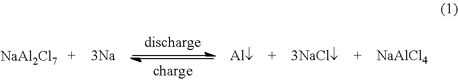
Battery 100 is typically assembled in a charged state, thus the first stage of a cycle is a discharge. NaAl.sub.2Cl.sub.7 will transform to NaAlCl.sub.4 first (point "a" to point "b" in FIG. 2), as shown in equation (1).
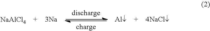
##STR00001## after which the composition on the phase diagram is NaCl:AlCl.sub.3=4:1 or 20 mol % AlCl.sub.3. NaAlCl.sub.4 then becomes the catholyte, which can continue the discharge as shown in equation (2).
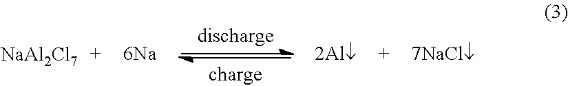
##STR00002## Therefore, the total cell reaction is:
##STR00003##
The theoretical capacity of the NaAl.sub.2Cl.sub.7 catholyte can be expressed as the number of coulombs generated per gram (g) of active material C=nF/M (M the molecular weight in g), but is more commonly reported as the time needed to pass this charge as a current (1 amp=1 coulomb/second) in units, such as hours of time at mA current, so that: C=nF/M coulombs g.sup.-1=nF/M Amp-sec g.sup.-1=nF/M.times.1000/3600 mAhg.sup.-1 (4) Substitution of n=6, F=96,500, and M=325.5 g, yields C=494 mAhg.sup.-1.
It may be preferable that the aluminum in the NaAl.sub.2Cl.sub.7 catholyte not be fully deposited, such that liquid NaAlCl.sub.4 is present to serve as the electrolyte for Na.sup.+ flux in the subsequent re-charge process. That is, according to the phase diagram in FIG. 2, this second step discharge does not reach pure NaCl, but can stop at point "c." Therefore, the practical capacity of this catholyte is understood to be lower than 494 mAhg.sub.-1.
FIG. 3 shows electrochemical behavior of NaAl.sub.2Cl.sub.7 in the form of cyclic voltammograms taken at T=200.degree. C., with a platinum reference electrode, and a scan rate of 10 mVs.sup.-1. The scan covers the potential range that includes the reduction to metallic aluminum at the negative extreme and the oxidation of chloride ion to chlorine gas at the positive extreme. The redox process for the Al/Al(III) couple is reversible.
A Na--Al battery was constructed as depicted in FIG. 4. Battery 400 includes cathode chamber 402 and anode chamber 404. Cathode chamber 402 includes cathode 406 and catholyte 408. Anode chamber 404 includes anode 410 and anolyte 412, both of which are molten. Sodium ion conductor 414 separates cathode chamber 402 and anode chamber 404. Cathode 402 and catholyte 408, initially NaAl.sub.2Cl.sub.7, were contained with aluminum foil 415. Anolyte 412 was placed above sodium ion conductor (separator) 414, which was optionally coated with an electronically conductive metal oxide (e.g., indium tin oxide) to improve wettability, and catholyte 408 (NaAl.sub.2Cl.sub.7), absorbed in aluminum wool 416, was placed below the sodium ion conductor. Aluminum wool 416 served as a current collector and also has wicking effect to allow catholyte 408 to contact sodium ion conductor 414. Cathode chamber 402 and anode chamber 404 were sealed with gasket 418.
Working at 200.degree. C., discharge and charge behaviors at 0.1 C were recorded and are shown in FIGS. 5A and 5B for a Na--Al battery at 0.1 C with NaAl.sub.2Cl.sub.7 catholyte and NaAl.sub.2Cl.sub.7-EMIAlCl.sub.4 (4:1 mole ratio) catholyte, respectively, where EMIAlCl.sub.4 is a mixture of 1-ethyl-3-methylimidazolium chloride and AlCl.sub.3. The capacity is calculated on the basis of the mass of NaAl.sub.2Cl.sub.7. After a short initial high voltage stage, the discharge voltage dropped and stabilized at about 1.5 V. When 296 mAhg.sup.-1 had been delivered, corresponding to 59.9% of the available Al being used, the discharge voltage dropped to about 1.3 V. At this point, the composition in the cathode chamber was NaAlCl.sub.4, NaCl, and Al. After the battery was recharged, the voltage was about 1.63 V. The solid NaCl that formed during discharge did not establish sufficient contact with the remaining NaAlCl.sub.4 for the charging process to regenerate all the initial liquid NaAl.sub.2Cl.sub.7. A second discharge curve yielded a smaller capacity.
In some implementations, a low-melting component such as the "ionic liquid" EMIAlCl.sub.4 is added to the electrolyte to increase the liquid volume and improve wetting. EMIAlCl.sub.4 is inactive in the charge/discharge process and the aluminum in it generally cannot be deposited. It is in the liquid state, but causes the conductivity of the NaAl.sub.2Cl.sub.7-EMIAlCl.sub.4 (mole ratio 4:1) mixture to become lower than for pure NaAl.sub.2Cl.sub.7 due at least in part to an alkali cation trapping phenomenon, as shown in FIG. 6. FIG. 6 shows specific conductivities of NaAl.sub.2Cl.sub.7, EMIAlCl.sub.4, and their mixtures. All data from three consecutive runs coincided within measurement uncertainty. The addition of EMIAlCl.sub.4 contributes toward a lower melting point of NaAl.sub.2Cl.sub.7.
An improved charge/discharge profile with this catholyte is shown in FIG. 5B. The voltage during the initial discharge is around 1.3 V, but in the following charge-discharge, the discharge and charge voltages are 1.56 V and 1.63 V, respectively, which are the same as with the pure NaAl.sub.2Cl.sub.7 battery (FIG. 5A), and the capacity is higher (>300 mAhg.sup.-1, >61% Al usage) for the second and third cycles. The energy efficiency (product of Coulomb and voltage efficiencies) is high, about 95.7%.
In some implementations, the discharge is limited to a shallow value such that the cell process can be described by the equation
##STR00004## in which no solid NaCl is generated.
Some implementations include, in the cathode chamber, a supply of an adduct of AlCl.sub.3 with some appropriate (molecular) base chosen to maintain the activity of AlCl.sub.3 at about the same value as that in liquid NaAl.sub.2Cl.sub.7. This effectively buffers the electrolyte against NaCl precipitation and removes the volume change in the electrolyte from cell design consideration. The cell design can be modified to use a minimum electrolyte volume, and the capacity can be determined by the amount of AlCl.sub.3 in the adduct. The AlCl.sub.3 adduct, unlike NaCl, would be a soft solid that would readily release AlCl.sub.3 to the electrolyte to maintain an optimum activity for Al deposition. To minimize the effect on the capacity, the base may have a low molecular weight, and may be inorganic. The cell reaction may reduce to the transfer of AlCl.sub.3 to the electrolyte as NaAl.sub.2Cl.sub.7 to accommodate the in-migration of Na.sup.+, effectively making the cell reaction 3Na+AlCl.sub.3=Al+3NaCl (6) coupled with the acid-base process using AlCl.sub.3 from the bank, viz., 3NaCl+6AlCl.sub.3=3NaAl.sub.2Cl.sub.7 (7) to maintain the liquid state of the electrolyte at 110.degree. C., and give an overall cell reaction 3Na+7AlCl.sub.3=Al+3NaAl.sub.2Cl.sub.7 (8) Alternatively, it could be 3Na+4AlCl.sub.3=Al+3NaAlCl.sub.4 (9) if a higher operating temperature (T>158.degree. C.) is used.
The mass of AlCl.sub.3 needed to keep the NaCl in the low temperature (chloroaluminate) liquid state at constant AlCl.sub.3 activity is included in the cell capacity calculation. Using an AlCl.sub.3 storage bank can simplify the cell design because the volume change (formerly entirely residing in the electrolyte) is shared with the volume change in the AlCl.sub.3 bank.
Table 1 provides a comparison with the lithium-ion battery and Na--NiCl.sub.2 (ZEBRA) battery. The theoretical energy density can be obtained as the product of cell capacity in Coulombs per gram of active material from the cell equation and cell voltage, E=QV/M=nF/M.times.V, where the units will be Jg.sup.-1, but is usually expressed in units of Whkg.sup.-1, and obtained from the product of cell voltage and capacity, the latter expressed in the practical units of mAhg.sup.-1. Thus the theoretical energy density, assuming the cell voltage remains steady at the observed value of 1.6 V until all Al is consumed, would be 494 mAhg.sup.-1.times.1.60 V (the average of charge and discharge voltages) or 790 Whkg.sup.-1. However, as seen in FIG. 5B, only 60% of the theoretical capacity is realized. Thus, the experimental energy density is 790.times.0.6=480 Whkg.sup.-1, which is close to that of the lithium ion battery (608 Whkg.sup.-1, based on active cathode mass alone). The ZEBRA battery has a high theoretical capacity (787 Whkg.sup.-1), but this value would be lower if one were to take the liquid NaAlCl.sub.4 electrolyte into account in the calculation. Moreover, because of slow diffusion within the solid NiCl.sub.2 formed on the nickel surface, only a part of Ni can be utilized.
TABLE-US-00001 TABLE 1 Comparisons among three kinds of batteries. Li-ion battery Na--NiCl.sub.2 battery Na--Al battery Cathode LiFePO.sub.4 NiCl.sub.2 NaAl.sub.2Cl.sub.7 (capacity) (170 mAhg.sup.-1) (414 mAhg.sup.-1) (296 .ltoreq. C < 494 mAhg.sup.-1) Anode graphite sodium sodium (capacity) (372 mAhg.sup.-1) (1165 mAhg.sup.-1) (1165 mAhg.sup.-1) Electrolyte LiFP.sub.6 in NaAlCl.sub.4 NaAl.sub.2Cl.sub.7 and organic solvent NaAlCl.sub.4 Separator polymer Na.sup.+ solid Na.sup.+ solid conductor conductor Theoretical capacity 117 mAhg.sup.-1 305 mAhg.sup.-1 236 .ltoreq. C < 347 mAhg.sup.-1 (based on cathode and anode) Voltage 3.4 V 2.58 V 1.55 V Energy density 398 Whkg.sup.-1 787 Whkg.sup.-1 366 .ltoreq. E < 538 Whkg.sup.-1 Working room temperature 270-350.degree. C. about 200.degree. C. temperature Safety dendrite problem Safe Safe and organic electrolyte Cost of materials cheap cheaper cheapest Replenishable no no yes
For the Na--Al cell, both the sodium and aluminum are earth-abundant and inexpensive. It should therefore be much cheaper than the lithium-ion battery, and in view of the greater cost of Ni over Al, it should also be cheaper than the ZEBRA battery. In the charged state, both the catholyte and the anolyte are liquid, so they can be replaced after the performance degrades without discarding the whole battery. This would offer a further cost advantage over other battery types. Concerning safety, if the Na.sup.+ conducting separator should crack, sodium would react with NaAl.sub.2Cl.sub.7, to form NaCl and Al, being in this respect as safe as the ZEBRA battery.
In summary, molten NaAl.sub.2Cl.sub.7 can serve as a catholyte and can deliver a high capacity of 296.4 mAhg.sup.-1 at 60% depth of discharge; a 1.55 V discharge voltage, which is higher than expected from aqueous solution potential data, can be obtained with the molten salt medium. NaAl.sub.2Cl.sub.7 as catholyte and molten sodium as anolyte yields a high energy efficiency Na--Al battery. Its high energy density, low cost, high safety, and replenishable reserves make the Na--Al battery particularly promising in the grid-storage market.
Experimental
Materials and catholyte preparation: NaCl, anhydrous AlCl.sub.3 and 1-ethyl-3-methylimidazolium chloride (EMICl), were purchased from Sigma-Aldrich. Al wool was purchased from Lustersheen. NaSICON was supplied gratis by Ceramatec. The preparation of the NaAl.sub.2Cl.sub.7 and EMIAlCl.sub.4 mixed electrolyte was achieved by mixing of NaCl, AlCl.sub.3 and EMICl according to the molar ratio needed. The mixing of AlCl.sub.3 and NaCl cannot produce a liquid NaAl.sub.2Cl.sub.7 until the temperature is raised above the liquidus temperature, about 158.degree. C. After cooling down, solid NaAl.sub.2Cl.sub.7 (a mixture of NaAlCl.sub.4 and AlCl.sub.3 according to the phase diagram) was obtained and ground into powder for later use.
The electrochemical property of the catholyte was investigated by cyclic voltammetry (CV) using a potentiostat/galvanostat (Princeton Applied Research, VMP2). A three-electrode cell was employed with platinum as the working and counter electrodes, as well as the reference electrode. The scan was made at 200.degree. C. with a scan rate of 10 mV s.sup.-1.
Conductivity determinations: Conductivities of NaAl.sub.2Cl.sub.7, EMIAlCl.sub.4, and their mixtures were surveyed using twin platinum wire dip-type electrodes sealed into a stainless steel threaded caps that were screwed onto glass vials containing the samples loaded under argon in a drybox. Data were taken using a PAR VMP2 potentiostat (Princeton Applied Research) in the frequency range 10-100K Hz, during slow heating from ambient to 200.degree. C.
The battery depicted in FIG. 4 is a planar design utilizing flat viton gaskets to seal the anode and cathode chambers. To overcome the problems of ceramic wetting by liquid alkali metal, a light sputtering of indium-tin oxide (ITO) was used to reduce the surface tension and allow spreading of the sodium anode on the separator during an initial exposure of the anode compartment to 300.degree. C. The sodium was placed on the top to get good wetting of the NaSICON. Al wool, to serve as the current collector, was pressed into a pellet to fill in the cathode chamber. It also provides a wicking effect that ensures effective catholyte contact with the NaSICON separator. During the assembly, solid NaAl.sub.2Cl.sub.7 and liquid EMIAlCl.sub.4 at room temperature were placed on the top of the Al pellet and heated to 200.degree. C. to melt NaAl.sub.2Cl.sub.7 and allow them to be absorbed into the wool. An Al foil bowl was used to keep the liquid in place. The anode and cathode compartments were then joined and sealed, via insulated bolts and a second viton gasket, and the unit mounted in a controlled temperature oven for testing. After the temperature stablized at 200.degree. C., the battery test was commenced, using a battery test system from LAND Electronics Co.
Only a few implementations are described and illustrated. Variations, enhancements and improvements of the described implementations and other implementations can be made based on what is described and illustrated in this document.
* * * * *
C00001
C00002
C00003
C00004
D00000
D00001
D00002
D00003
D00004
D00005
XML
uspto.report is an independent third-party trademark research tool that is not affiliated, endorsed, or sponsored by the United States Patent and Trademark Office (USPTO) or any other governmental organization. The information provided by uspto.report is based on publicly available data at the time of writing and is intended for informational purposes only.
While we strive to provide accurate and up-to-date information, we do not guarantee the accuracy, completeness, reliability, or suitability of the information displayed on this site. The use of this site is at your own risk. Any reliance you place on such information is therefore strictly at your own risk.
All official trademark data, including owner information, should be verified by visiting the official USPTO website at www.uspto.gov. This site is not intended to replace professional legal advice and should not be used as a substitute for consulting with a legal professional who is knowledgeable about trademark law.