Decorative lighting control
Chen
U.S. patent number 10,683,974 [Application Number 16/216,800] was granted by the patent office on 2020-06-16 for decorative lighting control. This patent grant is currently assigned to Willis Electric Co., Ltd.. The grantee listed for this patent is Willis Electric Co., Ltd.. Invention is credited to Johnny Chen.


View All Diagrams
| United States Patent | 10,683,974 |
| Chen | June 16, 2020 |
Decorative lighting control
Abstract
A multi-sectional artificial tree with internal and external power wiring for distributing and controlling power to a network of lights. The tree includes multiple tree sections, each tree section with a set of power wires inside a tree trunk, and a network of lighting wires outside the trunk. The network of lighting wires includes a tree-section wire network with a large gauge wire supplying power to groups of lights strings on branches on the tree trunk. Each group of branches has a branch-level lighting network with multiple connectors in series, and that connects to one connector of the tree-section wire network. Each branch-level lighting network powers multiple light strings connected in series, one light string per branch. The wires of the light strings are small gauge, and are connected by the branch-level connectors by a small-wire-to-large-wire connector.
| Inventors: | Chen; Johnny (Taipei, TW) | ||||||||||
|---|---|---|---|---|---|---|---|---|---|---|---|
| Applicant: |
|
||||||||||
| Assignee: | Willis Electric Co., Ltd.
(Taipei, TW) |
||||||||||
| Family ID: | 71074972 | ||||||||||
| Appl. No.: | 16/216,800 | ||||||||||
| Filed: | December 11, 2018 |
Related U.S. Patent Documents
| Application Number | Filing Date | Patent Number | Issue Date | ||
|---|---|---|---|---|---|
| 62597358 | Dec 11, 2017 | ||||
| Current U.S. Class: | 1/1 |
| Current CPC Class: | A47G 33/08 (20130101); F21V 23/06 (20130101); A47G 33/06 (20130101); F21S 4/10 (20160101); F21S 4/15 (20160101); A47G 33/0863 (20130101); F21S 4/22 (20160101); A47G 2033/0827 (20130101); A47G 2200/08 (20130101); F21W 2121/04 (20130101) |
| Current International Class: | F21S 4/15 (20160101); A47G 33/08 (20060101); F21S 4/22 (20160101); F21V 23/06 (20060101); F21S 4/10 (20160101); A47G 33/06 (20060101) |
References Cited [Referenced By]
U.S. Patent Documents
| 377953 | February 1888 | Mills |
| 438310 | October 1890 | Edison |
| 735010 | July 1903 | Zahl |
| 860406 | July 1907 | McGahan |
| 1314008 | August 1919 | McWilliams |
| 1372777 | March 1921 | Samuel et al. |
| 1495695 | May 1924 | Karr |
| 1536332 | May 1925 | Dam |
| 1590220 | June 1926 | Wurts |
| 1694974 | December 1928 | Glover |
| 2025189 | December 1935 | Yanchenko |
| 2050364 | August 1936 | Morton |
| 2072337 | March 1937 | Kamm |
| 2112281 | March 1938 | Ferris |
| 2186351 | January 1940 | Stojaneck |
| 2188529 | January 1940 | Corina |
| 2201045 | May 1940 | Lundstrom |
| 2229211 | January 1941 | Korengold |
| 2679911 | August 1948 | Bhend |
| 2466499 | April 1949 | Sokolik |
| 2484596 | October 1949 | Waltz |
| 2533374 | December 1950 | Hyland |
| 2563713 | August 1951 | Frei et al. |
| 2570751 | October 1951 | Benander |
| 2636069 | April 1953 | Gilbert |
| 2782296 | February 1957 | Walter |
| 2806938 | September 1957 | Henry |
| 2857506 | October 1958 | Minteer |
| 2863037 | December 1958 | Johnstone |
| 2910842 | November 1959 | Sensenig |
| 2932811 | April 1960 | Abraham et al. |
| 2969456 | January 1961 | Raymaley |
| 2973546 | March 1961 | Roche |
| 2984813 | May 1961 | Bossi |
| 3107966 | October 1963 | Bonhomme |
| 3115435 | December 1963 | Abramson |
| 3118617 | January 1964 | Hellrich |
| 3120351 | February 1964 | Kirsten |
| 3131112 | April 1964 | Abramson |
| 3214579 | October 1965 | Pacini |
| 3233207 | February 1966 | Ahroni et al. |
| 3286088 | November 1966 | Ahroni |
| 3296430 | January 1967 | Eckert |
| 3345482 | October 1967 | Lou |
| 3398260 | August 1968 | Martens |
| 3409867 | November 1968 | Lessner |
| 3470527 | September 1969 | Bonhomme |
| 3504169 | March 1970 | Freeburger |
| 3513063 | March 1970 | Sloane |
| 3521216 | July 1970 | Tolegian |
| 3522579 | August 1970 | Matsuya |
| 3571586 | March 1971 | Duckworth |
| 3574102 | April 1971 | Hermanson |
| 3585564 | June 1971 | Skjervoll |
| 3594260 | July 1971 | Dieffenbach |
| 3603780 | September 1971 | Lu |
| 3616107 | October 1971 | Kershner |
| 3617732 | November 1971 | Fisher |
| 3640496 | February 1972 | Duncan |
| 3663924 | May 1972 | Gerlat |
| 3704366 | November 1972 | Korb et al. |
| 3715708 | February 1973 | Lloyd et al. |
| 3728787 | April 1973 | McDonough |
| 3748488 | July 1973 | David, Jr. |
| 3764862 | October 1973 | Jankowski |
| 3783437 | January 1974 | Graff et al. |
| 3806399 | April 1974 | Cocjin |
| 3808450 | April 1974 | Davis, Jr. |
| 3812380 | May 1974 | Davis, Jr. |
| 3819457 | June 1974 | Mottel |
| 3819459 | June 1974 | Wren |
| 3834976 | September 1974 | Mottel |
| 3862434 | January 1975 | Davis, Jr. |
| 3864580 | February 1975 | Davis, Jr. |
| 3914786 | October 1975 | Grossi |
| 3970834 | July 1976 | Smith |
| 3971619 | July 1976 | Rohrssen |
| 3985924 | October 1976 | Pritza |
| 4012631 | March 1977 | Creager |
| 4020201 | April 1977 | Miller |
| 4045868 | September 1977 | Ammon et al. |
| 4057735 | November 1977 | Davis, Jr. |
| 4097917 | June 1978 | McCaslin |
| 4109345 | August 1978 | Sargent et al. |
| 4125781 | November 1978 | Davis, Jr. |
| 4140823 | February 1979 | Weskamp |
| 4153860 | May 1979 | Vonick |
| 4161768 | July 1979 | Gauthier et al. |
| 4215277 | July 1980 | Weiner et al. |
| 4245875 | January 1981 | Shaffer et al. |
| 4248916 | February 1981 | Chase |
| 4273814 | June 1981 | Koehler |
| 4291075 | September 1981 | Puleo |
| 4305980 | December 1981 | Koehler |
| 4340841 | July 1982 | Schupp |
| 4343842 | August 1982 | Chase |
| 4437782 | March 1984 | Geisthoff |
| 4447279 | May 1984 | Boisvert et al. |
| 4451510 | May 1984 | Boisvert et al. |
| 4462065 | July 1984 | Rhodes |
| 4493523 | January 1985 | Leong et al. |
| 4496615 | January 1985 | Huang |
| 4516193 | May 1985 | Murphy |
| 4519666 | May 1985 | Williams et al. |
| 4546041 | October 1985 | Keane et al. |
| 4573102 | February 1986 | Norwood |
| 4590105 | May 1986 | Shaffer |
| 4620270 | October 1986 | Laasko |
| 4631650 | December 1986 | Ahroni |
| 4636106 | January 1987 | Waisbrod |
| 4659597 | April 1987 | Lau |
| 4662775 | May 1987 | Faul |
| 4675575 | June 1987 | Smith et al. |
| 4678926 | July 1987 | Davis |
| 4712299 | December 1987 | Loewen et al. |
| 4720272 | January 1988 | Durand |
| 4727449 | February 1988 | Fleck |
| 4753600 | June 1988 | Williams |
| 4759729 | July 1988 | Kemppainen et al. |
| 4761720 | August 1988 | Solow |
| 4769579 | September 1988 | Jou |
| 4772215 | September 1988 | Falk |
| 4774113 | September 1988 | Shaffer |
| 4775922 | October 1988 | Engel |
| 4777573 | October 1988 | Liao |
| 4779177 | October 1988 | Ahroni |
| 4789570 | December 1988 | Maddock |
| 4799902 | January 1989 | Laudig et al. |
| 4805075 | February 1989 | Damore |
| 4807098 | February 1989 | Ahroni |
| 4808885 | February 1989 | Bausch et al. |
| 4812956 | March 1989 | Chen |
| 4855880 | August 1989 | Mancusi, Jr. |
| 4859205 | August 1989 | Fritz |
| 4867690 | September 1989 | Thumma |
| 4870547 | September 1989 | Crucefix |
| 4870753 | October 1989 | Pfeffer et al. |
| 4885664 | December 1989 | Hermanson |
| 4890000 | December 1989 | Chou |
| 4894019 | January 1990 | Howard |
| 4899266 | February 1990 | Ahroni |
| 4908743 | March 1990 | Miller |
| 4921426 | May 1990 | Kawasaki et al. |
| 4934964 | June 1990 | Mazelle |
| 5015510 | May 1991 | Smith |
| 5033976 | July 1991 | Sarian et al. |
| 5051877 | September 1991 | Liao |
| 5071362 | December 1991 | Martens et al. |
| 5073132 | December 1991 | Nottrott |
| 5088669 | February 1992 | Zinnbauer |
| 5091834 | February 1992 | Kao et al. |
| 5104608 | April 1992 | Pickering |
| 5109324 | April 1992 | Ahroni |
| 5121310 | June 1992 | Ahroni |
| 5128595 | July 1992 | Hara |
| 5139343 | August 1992 | Lin |
| 5149282 | September 1992 | Donato et al. |
| 5150964 | September 1992 | Tsui |
| 5154508 | October 1992 | Ahroni |
| 5213407 | May 1993 | Eisenbraun |
| 5217382 | June 1993 | Sparks |
| 5218233 | June 1993 | Takahashi |
| 5281158 | January 1994 | Lin |
| 5300864 | April 1994 | Allen, Jr. |
| 5334025 | August 1994 | Fohl |
| 5342661 | August 1994 | Wilcox, II |
| 5349780 | September 1994 | Dyke |
| 5350315 | September 1994 | Cheng et al. |
| 5366386 | November 1994 | Liao |
| 5376752 | December 1994 | Limeris et al. |
| 5380215 | January 1995 | Huang |
| 5389008 | February 1995 | Cheng et al. |
| 5390463 | February 1995 | Sollner |
| D356246 | March 1995 | Adams |
| 5409403 | April 1995 | Falossi et al. |
| 5422766 | June 1995 | Hack et al. |
| 5438154 | August 1995 | Segan et al. |
| 5442258 | August 1995 | Shibata |
| 5453664 | September 1995 | Harris |
| 5455750 | October 1995 | Davis et al. |
| 5456620 | October 1995 | Kaminski |
| 5481444 | January 1996 | Schulz |
| D367257 | February 1996 | Buelow et al. |
| 5492429 | February 1996 | Hodges |
| 5495147 | February 1996 | Lanzisera |
| 5517390 | May 1996 | Zins |
| 5518425 | May 1996 | Tsai |
| 5536538 | July 1996 | Hartung |
| 5541818 | July 1996 | Ng et al. |
| 5550720 | August 1996 | Carroll |
| 5559681 | September 1996 | Duarte |
| 5560975 | October 1996 | Casper |
| D375483 | November 1996 | Tashiro |
| 5580159 | December 1996 | Liu |
| 5586905 | December 1996 | Marshall et al. |
| 5605395 | February 1997 | Peng |
| 5607328 | March 1997 | Joly |
| 5624283 | April 1997 | Hotea |
| 5626419 | May 1997 | Lin |
| 5629587 | May 1997 | Gray et al. |
| 5639157 | June 1997 | Yeh |
| 5652032 | July 1997 | Kaczor et al. |
| 5653616 | August 1997 | Hotea |
| 5695279 | December 1997 | Sonnleitner et al. |
| 5702262 | December 1997 | Brown et al. |
| 5702268 | December 1997 | Lien et al. |
| 5707136 | January 1998 | Byers |
| 5709457 | January 1998 | Hara |
| 5712002 | January 1998 | Reilly, III |
| 5720544 | February 1998 | Shu |
| 5722766 | March 1998 | Shu |
| 5727872 | March 1998 | Liou |
| 5758545 | June 1998 | Fevre et al. |
| 5759062 | June 1998 | Chen |
| 5775933 | July 1998 | Chen |
| 5776559 | July 1998 | Woolford |
| 5776599 | July 1998 | Haluska et al. |
| 5785412 | July 1998 | Wu et al. |
| 5788361 | August 1998 | Lee |
| 5791765 | August 1998 | Lin |
| 5791940 | August 1998 | Chen et al. |
| 5807134 | September 1998 | Hara |
| 5816849 | October 1998 | Schmidt |
| 5816862 | October 1998 | Tseng |
| 5820248 | October 1998 | Ferguson |
| 5822855 | October 1998 | Szczesny et al. |
| 5828183 | October 1998 | Wang et al. |
| 5829865 | November 1998 | Ahroni |
| 5834901 | November 1998 | Shen |
| 5839819 | November 1998 | Pan |
| 5848838 | December 1998 | Presta |
| 5852348 | December 1998 | Lin |
| 5854541 | December 1998 | Chou |
| 5855705 | January 1999 | Gauthier |
| 5860731 | January 1999 | Martinez |
| 5860830 | January 1999 | Wu |
| 5869151 | February 1999 | Chong |
| 5878989 | March 1999 | Allman |
| 5893634 | April 1999 | Wang |
| 5908238 | June 1999 | Huang |
| 5921806 | July 1999 | Shuey |
| 5934793 | August 1999 | Rahman |
| 5937496 | August 1999 | Benoit et al. |
| 5938168 | August 1999 | Adams |
| 5957723 | September 1999 | Gort-Barten |
| 5966393 | October 1999 | Hide et al. |
| 5971810 | October 1999 | Taylor |
| 5979859 | November 1999 | Vartanov et al. |
| 6004006 | December 1999 | Wang |
| 6007362 | December 1999 | Davis et al. |
| 6030670 | February 2000 | Chang |
| 6042418 | March 2000 | Cummings |
| 6053774 | April 2000 | Lin |
| 6056427 | May 2000 | Kao |
| 6065233 | May 2000 | Rink |
| 6079848 | June 2000 | Ahroni |
| 6084357 | July 2000 | Janning |
| 6086395 | July 2000 | Lloyd et al. |
| 6091204 | July 2000 | Chen |
| 6095874 | August 2000 | Quaranta |
| 6099920 | August 2000 | Kao |
| 6102740 | August 2000 | Murakami et al. |
| 6111201 | August 2000 | Drane et al. |
| 6113430 | September 2000 | Wu |
| 6116563 | September 2000 | Tsai |
| 6117503 | September 2000 | Lee et al. |
| 6120312 | September 2000 | Shu |
| 6123433 | September 2000 | Chen |
| 6139376 | October 2000 | Ooya et al. |
| 6147367 | November 2000 | Yang et al. |
| 6149448 | November 2000 | Haller et al. |
| 6155697 | December 2000 | Ahroni |
| 6162515 | December 2000 | Hill |
| 6203169 | March 2001 | Coushaine et al. |
| 6217191 | April 2001 | Wu et al. |
| 6217199 | April 2001 | Lo |
| 6228442 | May 2001 | Coco |
| 6241559 | June 2001 | Taylor |
| 6245425 | June 2001 | McCullough et al. |
| 6257736 | July 2001 | Fehrenbach |
| 6257740 | July 2001 | Gibboney, Jr. |
| 6257793 | July 2001 | Lin |
| 6261119 | July 2001 | Green |
| 6273584 | August 2001 | Wang et al. |
| 6276120 | August 2001 | Adriaensen et al. |
| 6283797 | September 2001 | Wu |
| 6285140 | September 2001 | Ruxton |
| 6292901 | September 2001 | Lys et al. |
| 6320327 | November 2001 | Lavatelli et al. |
| 6328593 | December 2001 | Chang et al. |
| 6347965 | February 2002 | Pan |
| D454110 | March 2002 | Andre et al. |
| 6354719 | March 2002 | Pan |
| 6361186 | March 2002 | Slayden |
| 6361368 | March 2002 | Tseng |
| 6363607 | April 2002 | Chen et al. |
| 6368130 | April 2002 | Fukuda |
| 6394623 | May 2002 | Tsui |
| 6407411 | June 2002 | Wojnarowski et al. |
| 6452317 | September 2002 | Tseng |
| 6457839 | October 2002 | Grandoit |
| 6458435 | October 2002 | Lai |
| 6497496 | December 2002 | Wang |
| 6511206 | January 2003 | Fan Wong |
| 6514581 | February 2003 | Gregory |
| 6533437 | March 2003 | Ahroni |
| 6541800 | April 2003 | Barnett et al. |
| 6544070 | April 2003 | Radliff |
| 6547584 | April 2003 | Myer et al. |
| 6566824 | May 2003 | Panagotacos et al. |
| 6571340 | May 2003 | Lee |
| 6576844 | June 2003 | Kamata |
| 6580182 | June 2003 | Janning |
| 6582094 | June 2003 | Liu |
| 6588914 | July 2003 | Tang |
| 6592094 | July 2003 | Kao |
| 6592238 | July 2003 | Cleaver et al. |
| 6595657 | July 2003 | Shieh |
| D478310 | August 2003 | Andre et al. |
| 6601971 | August 2003 | Ko |
| 6604841 | August 2003 | Liu |
| 6609814 | August 2003 | Ahroni |
| 6619831 | September 2003 | Kanesaka |
| 6623291 | September 2003 | Tsai |
| 6634766 | October 2003 | Gordon |
| 6641417 | November 2003 | Tanaka |
| 6644836 | November 2003 | Adams |
| 6653797 | November 2003 | Puleo, Sr. et al. |
| D483721 | December 2003 | Kim et al. |
| 6666734 | December 2003 | Fukatsu |
| 6672750 | January 2004 | Kao |
| D486385 | February 2004 | Smith-Kielland et al. |
| 6733167 | May 2004 | Kao |
| 6752512 | June 2004 | Pan |
| 6774549 | August 2004 | Tsai et al. |
| 6794825 | September 2004 | Kao |
| 6805463 | October 2004 | Shieh |
| 6824293 | November 2004 | Chang |
| 6830358 | December 2004 | Allen |
| 6840655 | January 2005 | Shen |
| 6840802 | January 2005 | Shepherd |
| 6866394 | March 2005 | Hutchins et al. |
| 6869316 | March 2005 | Hinkle et al. |
| 6883951 | April 2005 | Wu |
| 6884083 | April 2005 | Shepherd |
| 6908215 | June 2005 | Wu |
| 6914194 | July 2005 | Fan |
| 6929383 | August 2005 | Janning |
| D509797 | September 2005 | Milan |
| 6942355 | September 2005 | Castiglia |
| 6951405 | October 2005 | Yao |
| 6957971 | October 2005 | Wu |
| 6962498 | November 2005 | Kohen |
| 7000999 | February 2006 | Ryan, Jr. |
| 7021598 | April 2006 | Kao |
| 7029145 | April 2006 | Frederick |
| 7045965 | May 2006 | Li et al. |
| 7052156 | May 2006 | Primeau |
| 7055980 | June 2006 | Wu |
| 7055981 | June 2006 | Yao |
| 7066628 | June 2006 | Allen |
| 7066739 | June 2006 | McLeish |
| 7088904 | August 2006 | Ryan, Jr. |
| 7108514 | September 2006 | Chen et al. |
| D530277 | October 2006 | Lin |
| 7132139 | November 2006 | Yang |
| 7144610 | December 2006 | Estes et al. |
| 7145105 | December 2006 | Gaulard |
| 7147518 | December 2006 | Marechal et al. |
| 7160140 | January 2007 | Mrakovich et al. |
| 7186050 | March 2007 | Dean et al. |
| 7192303 | March 2007 | Kohen |
| 7204720 | April 2007 | Shiu |
| 7207844 | April 2007 | Peng |
| 7235815 | June 2007 | Wang |
| 7253556 | August 2007 | Gibboney |
| 7253714 | August 2007 | Tsui |
| 7264392 | September 2007 | Massabki et al. |
| 7270450 | September 2007 | Chan |
| 7311566 | December 2007 | Dent |
| 7315692 | January 2008 | Chow |
| 7318744 | January 2008 | Kuo |
| 7326091 | February 2008 | Nania et al. |
| 7371115 | May 2008 | Hsieh et al. |
| 7393019 | July 2008 | Taga et al. |
| 7422489 | September 2008 | Tseng |
| D580355 | November 2008 | Hussaini et al. |
| 7445824 | November 2008 | Leung et al. |
| 7453194 | November 2008 | Gibboney |
| D582846 | December 2008 | Lett |
| 7462066 | December 2008 | Kohen |
| D585384 | January 2009 | Andre et al. |
| 7473024 | January 2009 | Gibboney |
| 7481555 | January 2009 | Huang |
| 7527508 | May 2009 | Lee et al. |
| 7554266 | June 2009 | Chen |
| D598374 | August 2009 | Sasada |
| 7575362 | August 2009 | Hsu |
| 7581870 | September 2009 | Massabki et al. |
| 7585187 | September 2009 | Daily et al. |
| 7585552 | September 2009 | Meseke |
| 7609006 | October 2009 | Gibboney |
| D608685 | January 2010 | Krize |
| 7652210 | January 2010 | White |
| D609602 | February 2010 | Krize |
| D611409 | March 2010 | Green et al. |
| 7695298 | April 2010 | Arndt et al. |
| 7893627 | February 2011 | Li |
| 7926978 | April 2011 | Tsai |
| D638355 | May 2011 | Chen |
| 8007129 | August 2011 | Yang |
| 8047700 | November 2011 | Massabki et al. |
| 8053042 | November 2011 | Loomis |
| 8062718 | November 2011 | Schooley |
| 8092255 | January 2012 | Wang |
| 8096833 | January 2012 | Tobey |
| 8100546 | January 2012 | Lutz et al. |
| 8113889 | February 2012 | Zhang et al. |
| 8132360 | March 2012 | Jin et al. |
| 8132649 | March 2012 | Rogers |
| 8203275 | June 2012 | Ruxton |
| 8235737 | August 2012 | Cheng et al. |
| 8298633 | October 2012 | Chen |
| 8348466 | January 2013 | Plumb et al. |
| D678211 | March 2013 | Chen |
| 8390306 | March 2013 | Hamann et al. |
| 8397381 | March 2013 | Tsai |
| 8450950 | May 2013 | McRae |
| 8454186 | June 2013 | Chen |
| 8454187 | June 2013 | Chen |
| 8469734 | June 2013 | Chen |
| 8469750 | June 2013 | Chen |
| D686523 | July 2013 | Chen |
| 8491323 | July 2013 | Ishibashi |
| 8534186 | September 2013 | Glucksman et al. |
| 8562175 | October 2013 | Chen |
| 8568015 | October 2013 | Chen |
| 8569960 | October 2013 | Chen |
| 8573548 | November 2013 | Kuhn et al. |
| 8592845 | November 2013 | Chen |
| D696153 | December 2013 | Chen |
| 8599108 | December 2013 | Kline et al. |
| 8608342 | December 2013 | Chen |
| 8641229 | February 2014 | Li |
| 8777648 | July 2014 | Kitajima et al. |
| 8853721 | October 2014 | Chen |
| 8863416 | October 2014 | Leung et al. |
| 8870404 | October 2014 | Chen |
| 8876321 | November 2014 | Chen |
| 8916242 | December 2014 | Fu et al. |
| 8959810 | February 2015 | Leung et al. |
| 8974072 | March 2015 | Chen |
| 9044056 | June 2015 | Chen |
| 9055777 | June 2015 | Chen |
| 9057493 | June 2015 | Simon et al. |
| 9066617 | June 2015 | Chen |
| 9119495 | September 2015 | Leung et al. |
| 9140438 | September 2015 | Chen |
| 9157587 | October 2015 | Chen |
| 9157588 | October 2015 | Chen |
| 9179793 | November 2015 | Chen |
| 9220361 | December 2015 | Chen |
| 9222656 | December 2015 | Chen |
| 9243788 | January 2016 | Chen |
| 9291318 | March 2016 | Benson |
| 9402498 | August 2016 | McRae |
| 9439528 | September 2016 | Chen |
| 9441800 | September 2016 | Chen |
| 9441823 | September 2016 | Chen |
| 9526286 | December 2016 | Chen |
| 9572446 | February 2017 | Chen |
| 9593831 | March 2017 | Chen |
| 9648919 | May 2017 | Chen |
| 9617074 | June 2017 | Chen |
| 9671097 | June 2017 | Chen |
| 9677748 | June 2017 | Chen |
| 9677749 | June 2017 | Chen |
| 9700169 | July 2017 | Wong |
| 9883556 | January 2018 | Chen |
| 10184654 | January 2019 | Chen |
| 10288235 | May 2019 | Chen |
| 10288236 | May 2019 | Chen |
| 2002/0002015 | January 2002 | Mochizuki et al. |
| 2002/0097573 | July 2002 | Shen |
| 2002/0109989 | August 2002 | Chuang |
| 2002/0118540 | August 2002 | Ingrassia |
| 2002/0149936 | October 2002 | Mueller et al. |
| 2003/0063463 | April 2003 | Sloan et al. |
| 2003/0096542 | May 2003 | Kojima |
| 2003/0121781 | July 2003 | Prohaska et al. |
| 2003/0142494 | July 2003 | Ahroni |
| 2003/0198044 | October 2003 | Lee |
| 2003/0198048 | October 2003 | Frederick |
| 2003/0206412 | November 2003 | Gordon |
| 2003/0218412 | November 2003 | Shieh |
| 2003/0231779 | December 2003 | Billington |
| 2004/0004435 | January 2004 | Hsu |
| 2004/0012950 | January 2004 | Pan |
| 2004/0080281 | April 2004 | Pan |
| 2004/0090770 | May 2004 | Primeau |
| 2004/0096596 | May 2004 | Palmer, III et al. |
| 2004/0105270 | June 2004 | Shieh |
| 2004/0115984 | June 2004 | Rudy et al. |
| 2004/0145916 | July 2004 | Wu |
| 2004/0161552 | August 2004 | Butts, Jr. |
| 2004/0182597 | September 2004 | Smith et al. |
| 2004/0246718 | December 2004 | Fan |
| 2005/0048226 | March 2005 | Gary et al. |
| 2005/0077525 | April 2005 | Lynch et al. |
| 2005/0122723 | June 2005 | Frederick |
| 2005/0201068 | September 2005 | Kramer et al. |
| 2005/0239308 | October 2005 | Cummings et al. |
| 2005/0249892 | November 2005 | Rocheleau |
| 2005/0286267 | December 2005 | Wang |
| 2006/0000634 | January 2006 | Arakawa |
| 2006/0048397 | March 2006 | King et al. |
| 2006/0093308 | May 2006 | Ryan, Jr. |
| 2006/0146578 | July 2006 | Kuo |
| 2006/0158138 | July 2006 | Walter |
| 2006/0164834 | July 2006 | Kao |
| 2006/0221609 | October 2006 | Ryan, Jr. |
| 2006/0270250 | November 2006 | Allen |
| 2006/0274556 | December 2006 | Massabki et al. |
| 2007/0091606 | April 2007 | Reed |
| 2007/0092664 | April 2007 | Chun |
| 2007/0159109 | July 2007 | Gibboney |
| 2007/0177402 | August 2007 | Wu |
| 2007/0230174 | October 2007 | Hicks et al. |
| 2007/0253191 | November 2007 | Chin et al. |
| 2007/0273296 | November 2007 | Janning |
| 2008/0007951 | January 2008 | Chan |
| 2008/0025024 | January 2008 | Yu |
| 2008/0049424 | February 2008 | Wang |
| 2008/0094828 | April 2008 | Shao |
| 2008/0107840 | May 2008 | Leung et al. |
| 2008/0149791 | June 2008 | Bradley |
| 2008/0186731 | August 2008 | Graham |
| 2008/0186740 | August 2008 | Huang et al. |
| 2008/0205020 | August 2008 | Vich |
| 2008/0218092 | September 2008 | Chang |
| 2008/0283717 | November 2008 | Kim et al. |
| 2008/0296604 | December 2008 | Chou et al. |
| 2008/0303446 | December 2008 | Ding |
| 2008/0307646 | December 2008 | Zaderej et al. |
| 2009/0002991 | January 2009 | Huang |
| 2009/0003012 | January 2009 | Hsu |
| 2009/0023315 | January 2009 | Pfeiffer |
| 2009/0059578 | March 2009 | Lau |
| 2009/0213620 | August 2009 | Lee |
| 2009/0260852 | October 2009 | Schaffer |
| 2009/0289560 | November 2009 | Oliva |
| 2010/0000065 | January 2010 | Cheng et al. |
| 2010/0053991 | March 2010 | Boggs |
| 2010/0067242 | March 2010 | Fung |
| 2010/0072747 | March 2010 | Krize |
| 2010/0099287 | April 2010 | Colburn et al. |
| 2010/0136808 | June 2010 | Vanzo |
| 2010/0159713 | June 2010 | Nishihira et al. |
| 2010/0195332 | August 2010 | Wasem |
| 2010/0196628 | August 2010 | Shooley |
| 2010/0263911 | October 2010 | Watanabe |
| 2011/0062875 | March 2011 | Altamura |
| 2011/0076425 | March 2011 | Cheng et al. |
| 2011/0228535 | September 2011 | Shao |
| 2011/0256750 | October 2011 | Chen |
| 2012/0002407 | January 2012 | Li et al. |
| 2012/0009360 | January 2012 | Fu et al. |
| 2012/0076957 | March 2012 | Chen |
| 2012/0098465 | April 2012 | Rothschild |
| 2013/0093334 | April 2013 | Lin et al. |
| 2013/0107514 | May 2013 | McNabb et al. |
| 2013/0108808 | May 2013 | Leung et al. |
| 2013/0119893 | May 2013 | Chen |
| 2013/0120971 | May 2013 | Chen |
| 2013/0163231 | June 2013 | Chen |
| 2013/0301245 | November 2013 | Chen |
| 2013/0301246 | November 2013 | Chen |
| 2013/0301247 | November 2013 | Chen |
| 2013/0308301 | November 2013 | Chen |
| 2013/0309908 | November 2013 | Sandoval et al. |
| 2014/0087094 | March 2014 | Leung et al. |
| 2014/0215864 | August 2014 | Fischer, Jr. et al. |
| 2014/0268689 | September 2014 | Chen |
| 2014/0287618 | September 2014 | Chen |
| 2014/0334134 | November 2014 | Loomis |
| 2015/0029703 | January 2015 | Chen |
| 2015/0070878 | March 2015 | Yu |
| 2015/0157159 | June 2015 | Leung et al. |
| 2015/0272250 | October 2015 | Chen |
| 2016/0007430 | January 2016 | Kidakarn |
| 2016/0021957 | January 2016 | Chen |
| 2016/0021958 | January 2016 | Chen |
| 2016/0033097 | February 2016 | Chen |
| 2016/0341408 | November 2016 | Altamura |
| 1182513 | Feb 1985 | CA | |||
| 2102058 | Apr 1992 | CN | |||
| 2242654 | Dec 1996 | CN | |||
| 1181693 | May 1998 | CN | |||
| 2332290 | Aug 1999 | CN | |||
| 2484010 | Apr 2002 | CN | |||
| 1509670 | Jul 2004 | CN | |||
| 2631782 | Aug 2004 | CN | |||
| 2751226 | Jan 2006 | CN | |||
| 100409504 | Sep 2007 | CN | |||
| 200982547 | Nov 2007 | CN | |||
| 100409506 | Aug 2008 | CN | |||
| 201121811 | Sep 2008 | CN | |||
| 201187701 | Jan 2009 | CN | |||
| 201829727 | May 2011 | CN | |||
| 201897194 | Jul 2011 | CN | |||
| 201898147 | Jul 2011 | CN | |||
| 201966240 | Sep 2011 | CN | |||
| 102224645 | Oct 2011 | CN | |||
| 202473314 | Oct 2012 | CN | |||
| 202613183 | Dec 2012 | CN | |||
| 203703878 | Jul 2014 | CN | |||
| 32 40 446 | Jul 1983 | DE | |||
| 8436328 | Apr 1985 | DE | |||
| 10235081 | Feb 2004 | DE | |||
| 434425 | Jun 1991 | EP | |||
| 0552741 | Jul 1993 | EP | |||
| 0342050 | Aug 1995 | EP | |||
| 0727842 | Aug 1996 | EP | |||
| 895742 | Feb 1999 | EP | |||
| 0920826 | Jun 1999 | EP | |||
| 1 049 206 | Nov 2000 | EP | |||
| 1763115 | Mar 2007 | EP | |||
| 2533374 | Dec 2012 | EP | |||
| 1215214 | Apr 1960 | FR | |||
| 1150390 | Apr 1969 | GB | |||
| 1245214 | Sep 1971 | GB | |||
| 2112281 | Jul 1983 | GB | |||
| 2137086 | Oct 1984 | GB | |||
| 2 169 198 | Jul 1986 | GB | |||
| 2172135 | Sep 1986 | GB | |||
| 2178910 | Feb 1987 | GB | |||
| 2208336 | Mar 1989 | GB | |||
| 2221104 | Jan 1990 | GB | |||
| 2396686 | Jun 2004 | GB | |||
| 2 454 546 | May 2009 | GB | |||
| H11121123 | Apr 1999 | JP | |||
| WO 91/10093 | Jul 1991 | WO | |||
| WO 96/24966 | Aug 1996 | WO | |||
| WO 96/26661 | Sep 1996 | WO | |||
| WO 2002/075862 | Sep 2002 | WO | |||
| WO 2004/008581 | Jan 2004 | WO | |||
| WO 2007/140648 | Dec 2007 | WO | |||
| WO 2009/115860 | Sep 2009 | WO | |||
| WO 2010/082049 | Feb 2010 | WO | |||
Other References
|
Holtek, "HT2040A Christmas Light Controller" (Mar. 26, 1997) 9 pgs. cited by applicant . Mosdesign Semiconductor Corp. "8 Functions Xmas Light Control" (May 14, 2002) (2 pgs.). cited by applicant. |
Primary Examiner: Garlen; Alexander K
Attorney, Agent or Firm: Christensen, Fonder, Dardi & Herbert PLLC
Parent Case Text
PRIORITY CLAIM
This application claims the benefit of U.S. Provisional Patent Application No. 62/597,358, filed Dec. 11, 2017, which is incorporated herein in its entirety.
Claims
What is claimed is:
1. A multi-sectional artificial tree with internal and external power wiring for distributing and controlling power to a network of lights, the tree comprising: a first tree section configured to be oriented along a first lengthwise axis, comprising: a first tree trunk portion extending axially and defining a first internal cavity; a first plurality of branches distributed about a circumference of the first tree trunk portion such that each branch of the first plurality of branches is located at a same first axial level on the first tree trunk portion; a second plurality of branches distributed about the circumference of the first tree trunk portion such that each branch of the second plurality of branches is located at a same second axial level on the first tree trunk portion; a set of first internal trunk wires extending within the first internal cavity of the first tree trunk portion; a first tree trunk electrical connector located in the first internal cavity of the first tree trunk portion and in electrical connection with the set of first internal trunk wires; a first tree-section wiring network located external to the first tree trunk portion and in electrical connection with the set of first internal trunk wires, the first tree-section wiring network comprising a first plurality of tree-section wires, a first branch-level connector, and a second branch-level connector, each of the plurality of first tree-section wires comprising a multi-strand conductor and defining a first wire diameter size, the first branch-level connector located adjacent the first plurality of branches at the first axial level, the second branch-level connector located adjacent the second plurality of branches at the second axial level, the first branch-level connector electrically connected to the second branch-level connector in parallel; a first branch-level wiring network located at the first axial level and in electrical connection with the first branch-level connector, the first branch-level wiring network including a first plurality of light-string connectors connected to one another in series, the first plurality of light-string connectors comprising one light string connector per one branch of the first plurality of branches such that a quantity of branches of the first plurality of branches is the same as a quantity of the plurality of first light-sting connectors; a second branch-level wiring network located at the second axial level and in electrical connection with the second branch-level connector, the second branch-level wiring network including a second plurality of light-string connectors electrically connected to one another in series, the second plurality of light-string connectors comprising one light string connector per one branch of the second plurality of branches such that a quantity of branches of the second plurality of branches is the same as a quantity of the plurality of second light-sting connectors; a first plurality of light strings connected to the first plurality of branches and the first branch-level wiring network at the first axial level of the first tree trunk portion, each of the first plurality of light strings connected to only one of the first plurality of branches and to only one of the first plurality of light-string connectors, each of the first plurality of light strings including a pair of single-strand conductors and a plurality of light-emitting diodes electrically connected in parallel, each conductor of the pair of single-strand conductors defining a second wire diameter size that is smaller than the first wire diameter size; a second plurality of light strings connected to the second plurality of branches and the second branch-level wiring network at the second axial level of the first tree trunk portion, each of the second plurality of light strings connected to only one of the second plurality of branches and to only one of the second plurality of light-string connectors, each of the second plurality of light strings including a pair of single-strand conductors and a plurality of light-emitting diodes electrically connected in parallel, each conductor of the pair of single-strand conductors defining the second wire diameter size that is smaller than the first wire diameter size; and a second tree section, comprising: a second tree trunk portion defining a second internal cavity; a set of second internal trunk wires extending within the second internal cavity of the second tree trunk; a second tree trunk electrical connector located in the second internal cavity of the second tree trunk and in electrical connection with the set of second trunk wires; wherein the first tree section is configured to couple to the second tree section such that the first and second tree trunk portions are mechanically coupled, the first and second trunk electrical connectors are in electrical connection, and the sets of first and second internal trunk wires are in electrical connection.
2. The multi-sectional artificial tree of claim 1, further comprising a connector mounted in a sidewall of the first tree trunk portion, the connector in electrical connection with the set of first internal trunk wires and the first tree section wiring network.
3. The multi-sectional artificial tree of claim 1, wherein the first plurality of tree-section wires comprises 22 AWG wires and the conductors of the first and second plurality of light strings comprise wires that are in the range of 26 AWG to 30 AWG.
4. The multi-sectional artificial tree of claim 3, wherein each of the first plurality of light string connectors connects a 22 AWG wire to the wires that are in the range of 26 AWG to 30 AWG.
5. The multi-sectional artificial tree of claim 1, wherein the quantity of the first plurality of branches is more than the quantity of the second plurality of branches, the quantity of the plurality of the first plurality of light string connectors is more than the quantity of the second plurality of light string connectors, and the second branch-level wiring network further comprises a load resistor electrically connected in series to the plurality of second light string connectors such that a voltage at each of the first plurality of light string connectors is substantially the same as a voltage at each of the second plurality of light string connectors.
6. The multi-sectional artificial tree of claim 1, further comprising a controller assembly electrically connected to the set of first internal trunk wires.
7. The multi-sectional artificial tree of claim 6, wherein the controller assembly is releasably connected to the first tree trunk portion.
8. The multi-sectional artificial tree of claim 6, wherein the controller assembly comprises a timer.
9. The multi-sectional artificial tree of claim 1, further comprising an alternating current (AC) to direct current (DC) converter.
10. The multi-sectional artificial tree of claim 9, further comprising a controller assembly, and wherein the AC to DC converter is housed independently of the controller assembly, and is mechanically connected to the first tree trunk portion at a point independent of a connection of the controller assembly to the first tree trunk portion.
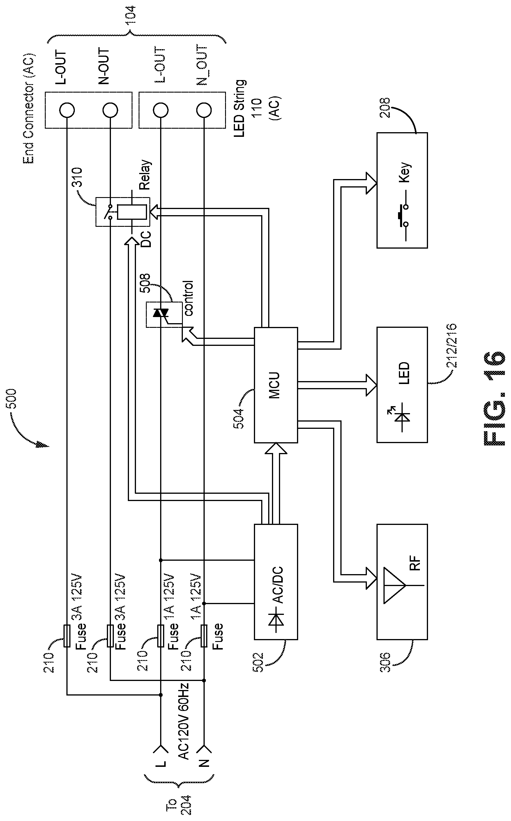
11. The multi-sectional artificial tree of claim 9, further comprising an end connector for providing AC power, and wherein the AC to DC converter is in electrical connection with the first and second plurality of light strings.
12. The multi-sectional artificial tree of claim 11, wherein the connector mounted to the sidewall of the first tree portion comprises a four-terminal connector, each terminal of the four-terminal connector being connected electrically with a fuse in series.
Description
FIELD OF THE DISCLOSURE
The present disclosure relates to decorative lighting control. More specifically, the present disclosure relates to devices, systems and methods of efficiently powering and controlling power and data of decorative lighting systems.
BACKGROUND OF THE DISCLOSURE
Basic control of lights of decorative lighting products, such as light strings, artificial lighted trees (pre-lit trees), net lights, icicle lights, to create lighting effects such as flashing, color changing, and so on, is well known. However, known systems and methods for controlling such lights remain deficient, as do wiring networks to selectively power and control the lights.
SUMMARY OF THE DISCLOSURE
Various embodiments of the disclosure include devices, systems and methods relating to control of decorative lighting. Embodiments include a variety of decorative lighting devices and systems that may be used for decoration, including holiday decoration, such as strings of lights, pre-lit or lighted artificial Christmas trees, icicle lights, net lights, and other such types of decorative lighting applications and apparatuses that may include LEDs, incandescent or other types of light elements. In some embodiments, a power source may provide an incoming alternating-current (AC) power, such as that provided to most homes and businesses. A decorative lighting device or system of the disclosure, such as one that includes light elements that comprise LEDs, may convert incoming AC power to direct-current (DC) power for use with control electronics and to power LEDs. In other embodiments, AC power may be used to power light elements that comprise incandescent or LED light elements.
In embodiments, both AC and DC power are utilized, for example, by providing AC power to a power receptacle of the decorative lighting device or system, and DC power to light elements. In an embodiment, a power receptacle transmitting AC power may be used to power an additional decorative lighting device or system, for example, a second string of lights, an AC-powered tree-top ornament, or another AC-powered device.
Embodiments of the disclosure include devices, systems and methods of controlling decorative lighting that utilizes AC power, DC power, or both. "Control" may include, but not be limited to methods for achieving light element color selection, brightness control, fading, flashing and other functions for selectively powering light elements on and off. While control systems and methods for achieving basic functions are known, embodiments of the present disclosure go further and incorporate system timing and control functions for both DC light elements and AC accessory power receptacles.
In one embodiment, the invention comprises a multi-sectional artificial tree with internal and external power wiring for distributing and controlling power to a network of lights. The tree includes multiple tree sections, each tree section with a set of power wires inside a tree trunk, and a network of lighting wires outside the trunk. The network of lighting wires includes a tree-section wire network with a large gauge wire supplying power to groups of lights strings on branches on the tree trunk. Each group of branches has a branch-level lighting network with multiple connectors in series, and that connects to one connector of the tree-section wire network. Each branch-level lighting network powers multiple light strings connected in series, one light string per branch. The wires of the light strings are small gauge, and are connected by the branch-level connectors by a small-wire-to-large-wire connector.
BRIEF DESCRIPTION OF THE DRAWINGS
The drawings included in the present application are incorporated into, and form part of, the specification. They illustrate embodiments of the present disclosure and, along with the description, serve to explain the principles of the disclosure. The drawings are only illustrative of certain embodiments and do not limit the disclosure.
FIG. 1 is a front view of a pre-lit tree controller, according to an embodiment;
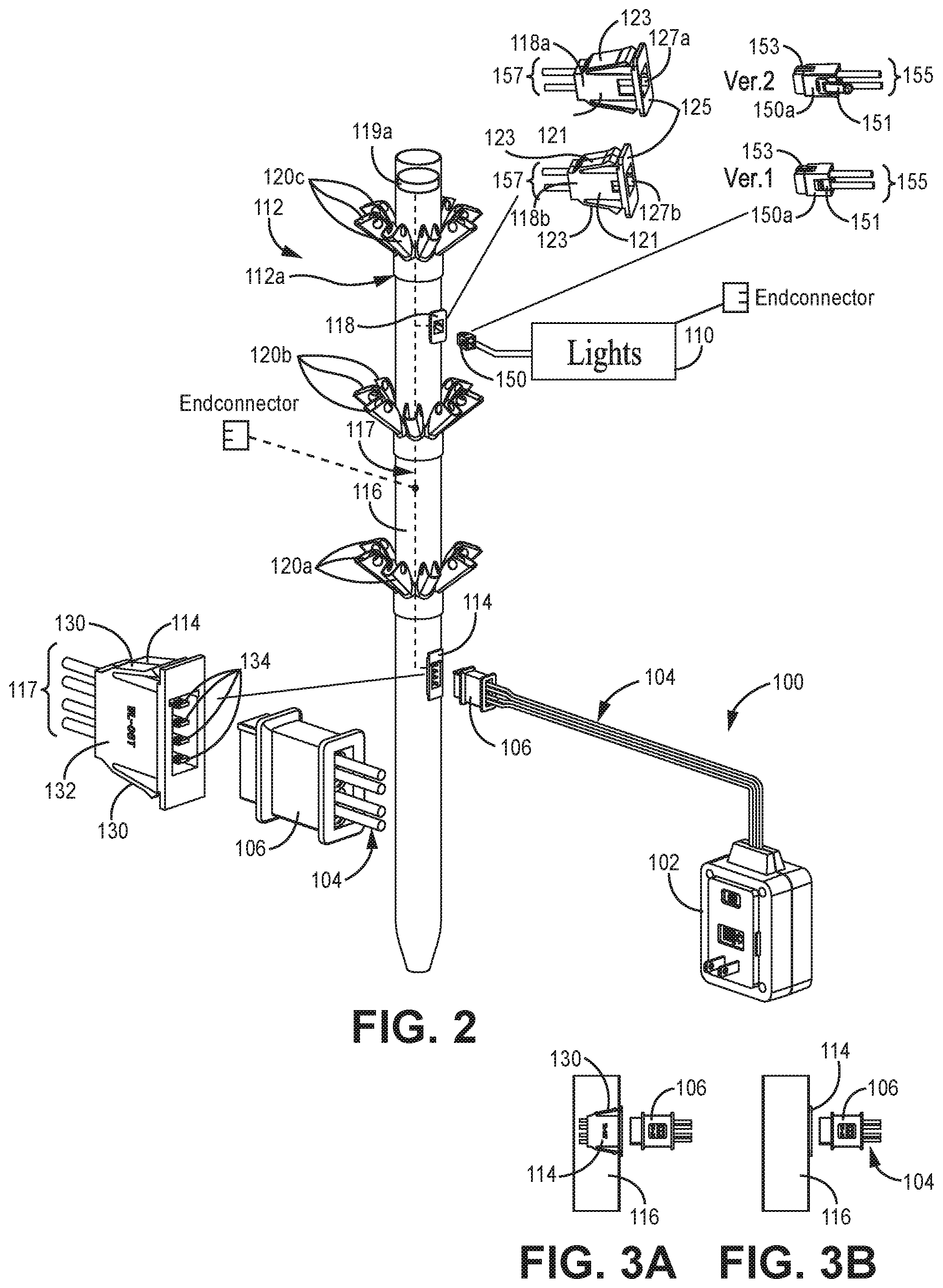
FIG. 2 is a perspective view of a pre-lit tree, according to an embodiment;
FIG. 3A is a partial sectional view of a trunk of the pre-lit tree of FIG. 2 with a pair of connectors;
FIG. 3B is a front view of a portion of the trunk and connectors of the pre-lit tree of FIG. 2;
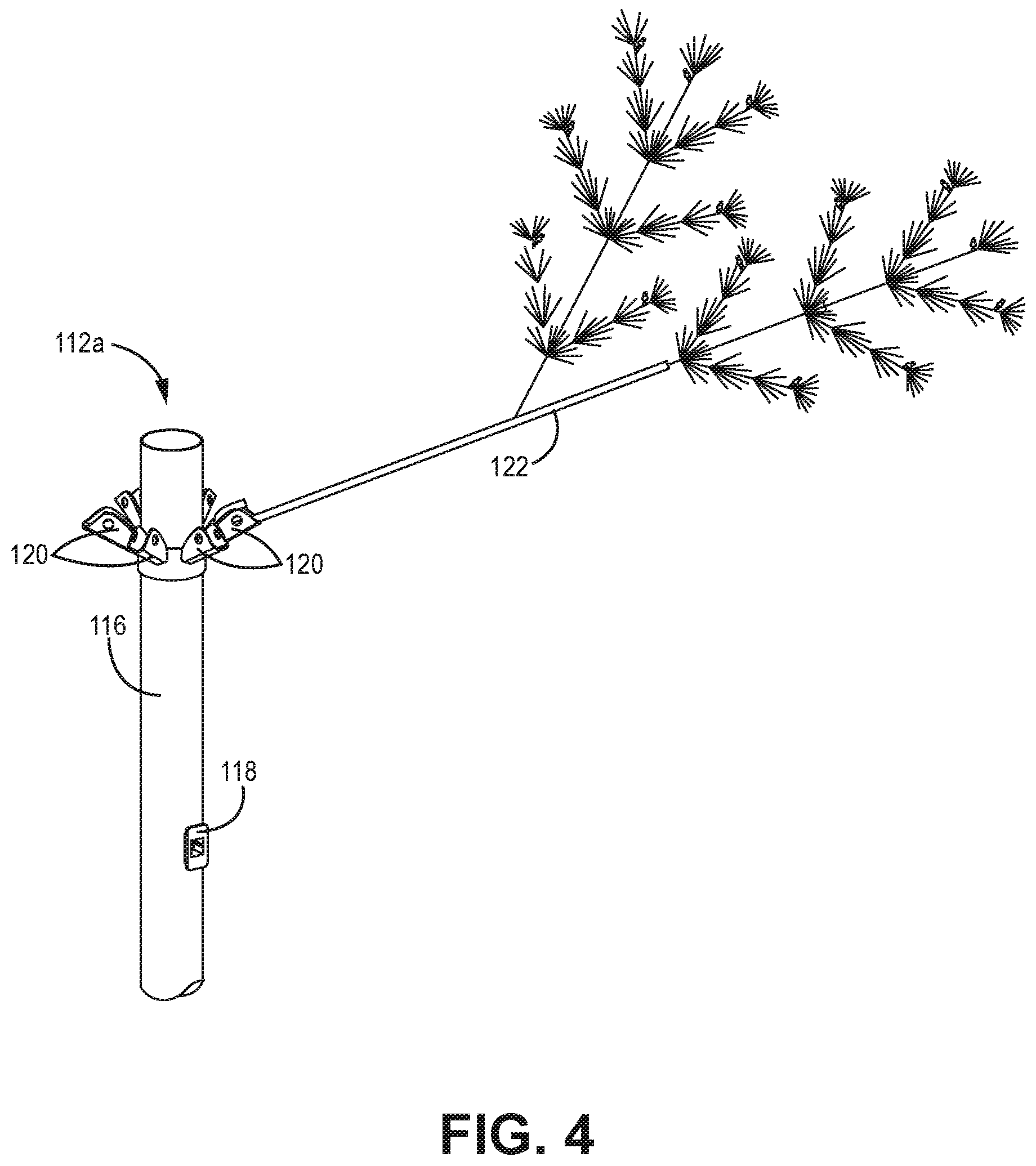
FIG. 4 is perspective view of a portion the pre-lit tree of FIG. 2, depicting a trunk with branch supports, branch, and a connector;
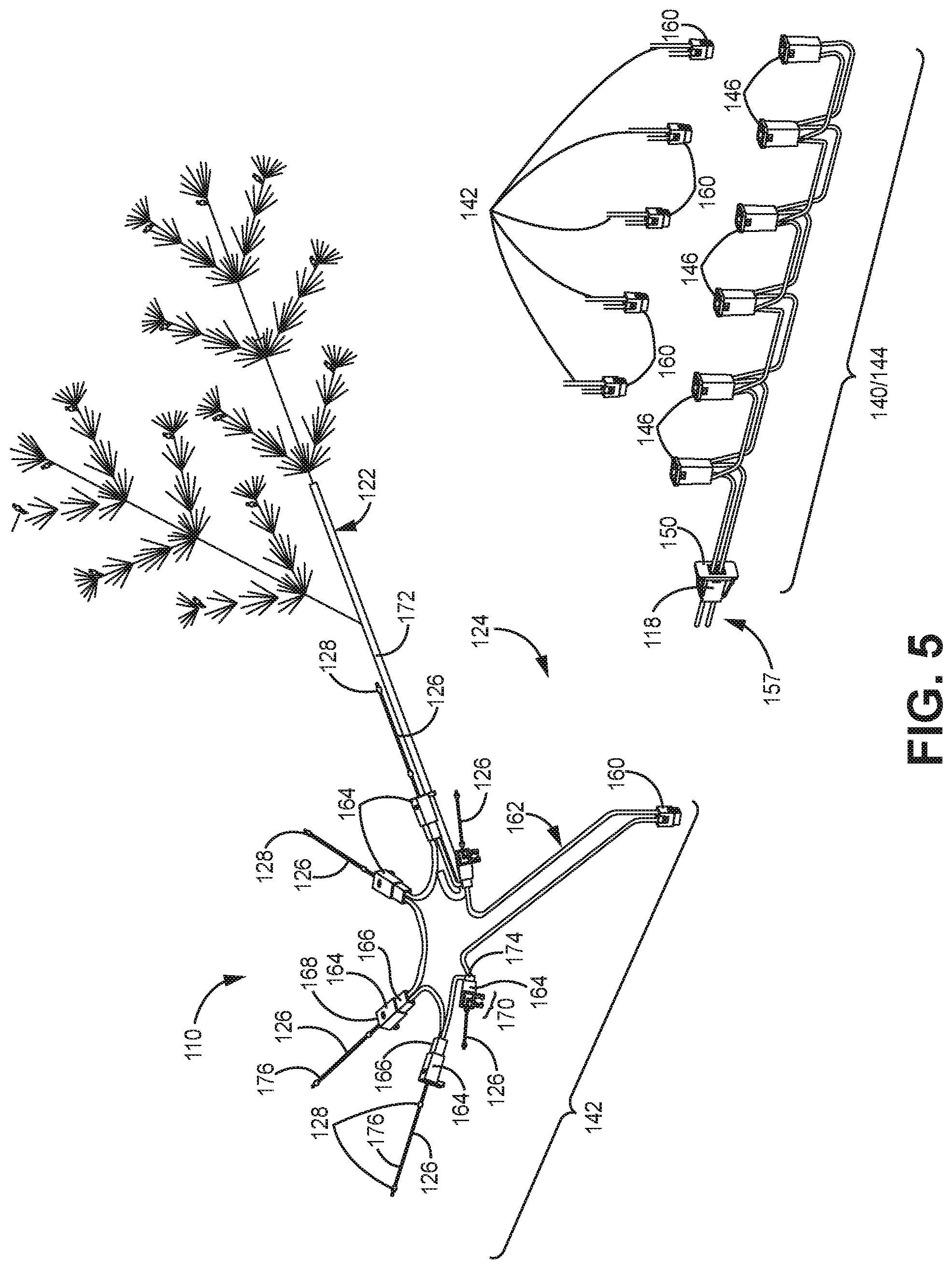
FIG. 5 is an exploded view of a light network, according to an embodiment;
FIG. 6 is perspective view of the portion of the pre-lit tree according to FIG. 4 with the light network of FIG. 5;
FIG. 7 is another perspective view of the portion of the pre-lit tree of FIG. 6, with additional branches and light network detail;
FIG. 8 is a front perspective view of a controller-timer, according to an embodiment;
FIG. 9 is a rear perspective view of the controller-timer of FIG. 8;
FIG. 10A is a rear view of the controller-timer of FIG. 8, in an embodiment that includes two fuses;
FIG. 10B is a rear view of the controller-timer of FIG. 8, in an embodiment that includes four fuses;
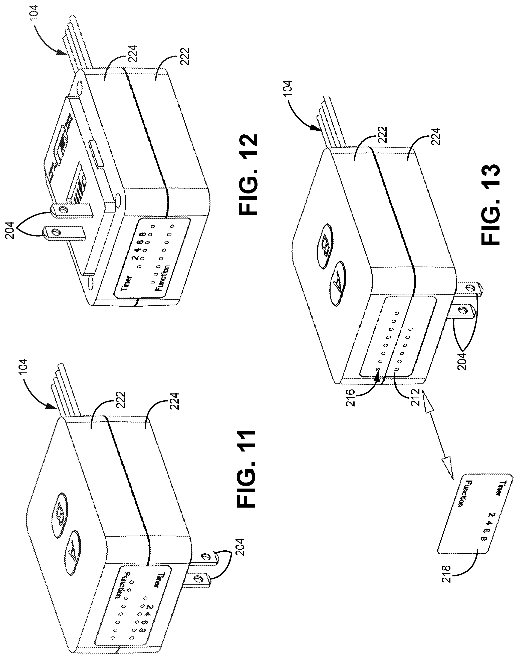
FIG. 11 is a left-side perspective view of the controller-timer of FIG. 8;
FIG. 12 is a right-side perspective view of the controller-timer of FIG. 8;
FIG. 13 is a left-side, partially exploded perspective view of the controller-timer of FIG. 8, with a film of function indicia;
FIG. 14 is a block diagram of a power and control circuit of a controller-timer for DC lights and an AC power receptacle, according to an embodiment;
FIG. 15 is a another block diagram of a power and control circuit of a controller-timer for DC lights and an AC power receptacle, according to an embodiment;
FIG. 16 is a block diagram of a power and control circuit of a controller-timer for AC lights and an AC power receptacle, according to an embodiment;
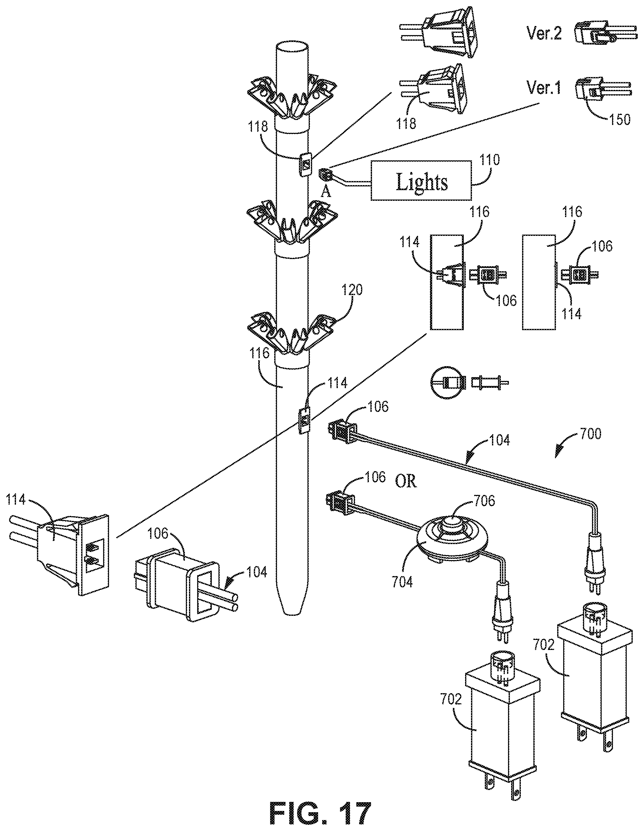
FIG. 17 is a perspective view of a pre-lit tree with a 2-pin DC controller, according to an embodiment;
FIG. 18 is a perspective view of a pre-lit tree with a 2-pin AC controller, according to an embodiment;
FIG. 19 is a block diagram of a 2-pin controller-timer for use with multiple light networks; and
FIG. 20 is a block diagram of a 4-pin controller-timer for use with multiple light networks.
While the embodiments of the disclosure are amenable to various modifications and alternative forms, specifics thereof have been shown by way of example in the drawings and will be described in detail. It should be understood, however, that the intention is not to limit the disclosure to the particular embodiments described. On the contrary, the intention is to cover all modifications, equivalents, and alternatives falling within the spirit and scope of the disclosure.
DETAILED DESCRIPTION OF THE FIGURES
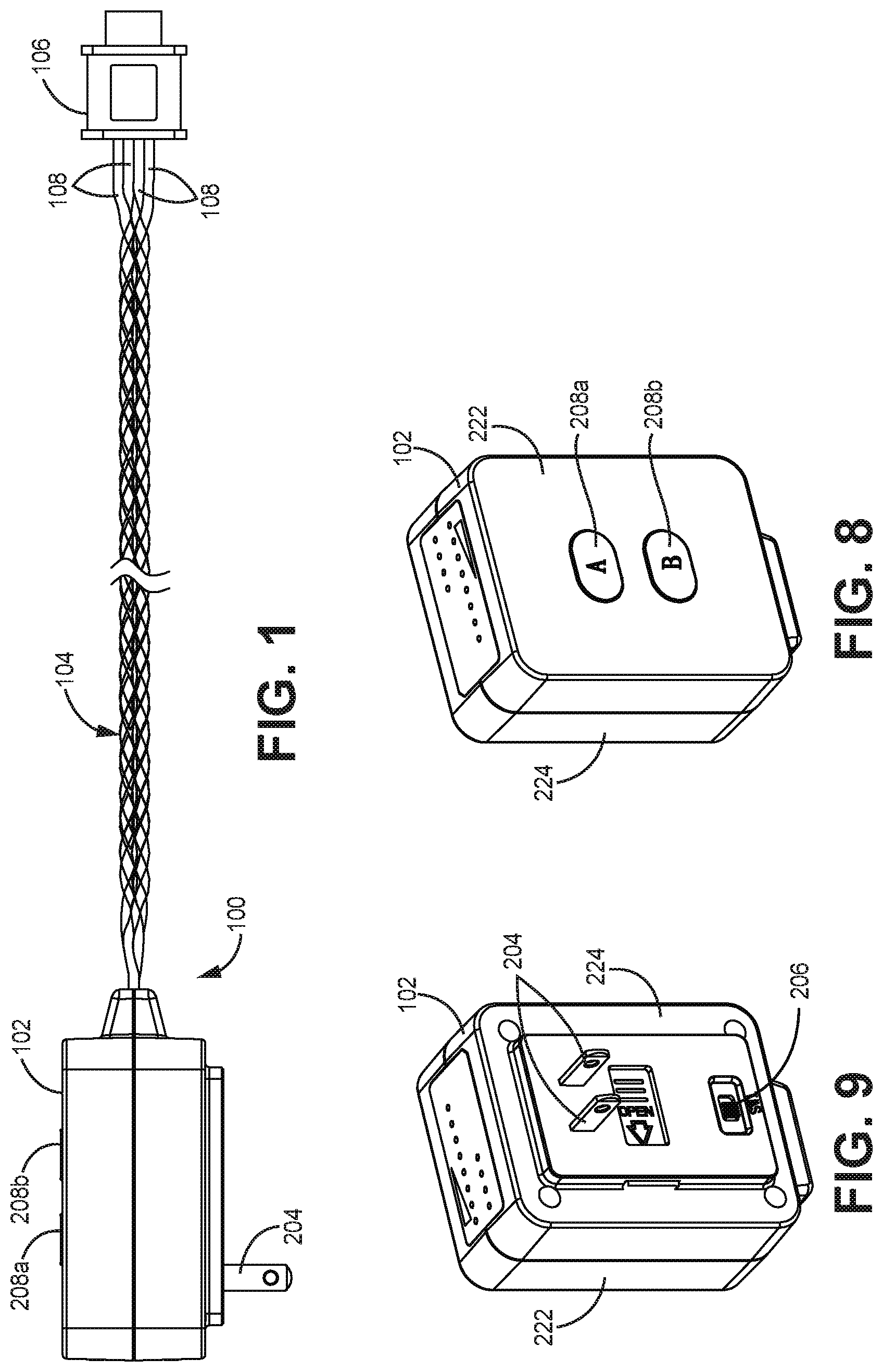
Referring to FIG. 1, an embodiment of a pre-lit tree controller 100 is depicted. In the embodiment depicted, pre-lit tree controller 100 includes controller-timer 102, wire bundle 104 and trunk connector 106 is depicted. Although the depicted embodiment of controller 100 is configured to mechanically and electrically connect to an artificial tree so as to control light elements of the artificial tree, it will be understood that other embodiments of controller 100 may be configured to connect to, and operate with, other types of decorative lighting and decorative lighting applications, such as light strings, net lights, icicle lights, and so on.
As depicted, wire bundle 104 includes a plurality of wires 108, each wire comprising an insulated conductor. In the embodiment depicted, wire bundle 104 includes four wires 108 connected to controller-timer 102. In other embodiments, wire bundle 104 may include more of fewer wires 108 depending on one or more considerations, such as functions of controller-timer 102, number and type of light elements controlled, tree design and so on.
Connector 106 receives wires 108 such that connector 106 is in electrically connected to controller-timer 102. As described further below, connector 106 may include multiple conductive electrical terminals. In an embodiment, each wire 108 is electrically connected to one of the multiple electrical terminals of connector 106. In on such embodiment, connector 106 includes four terminals connected to four wires 108 (as depicted); in another embodiment, connector 106 includes two terminals connected to two wires 108; in yet another embodiment, connector 106 includes six terminals connected to six wires 108.
Referring also to FIG. 2, in the embodiment depicted, controller-timer 102 comprises a controller that selectively controls light elements or lights of a light network 110 of an artificial tree 112, also referred to herein as a "pre-lit tree", such as pre-lit tree 112, to create various lighting effects.
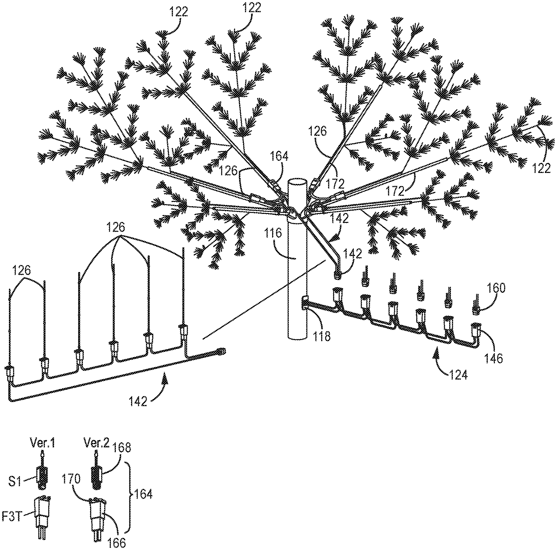
Referring to FIGS. 2-7, an embodiment of the disclosure includes pre-lit tree 112. In an embodiment, pre-lit tree 112 comprises pre-lit tree controller 100, controller connector 114, trunk portion 116, trunk wires 117, light connector 118, trunk connector 119, branch supports 120, branches 122, and light network 110. In an embodiment, and as depicted, branch supports 120 may comprise a plurality of sets of branch supports 120, each set having individual branches supports 120 being distributed uniformly about a circumference of trunk portion 116 at a particular point along a length of trunk portion 116. Three sets of branch supports 120 are depicted in FIG. 2, comprising a set "a" of branch supports 120a, set b of branch supports 120b, and a set c of branch supports 120c. In an embodiment, lights 110 may be distributed about and on branches 122. As described further below, in an embodiment, light network 110 comprises light-wiring network 124 with light strings 126 having light elements 128.
Referring specifically to FIG. 2, only a single section of tree 112 is depicted, first tree section 112a. However, it will be understood that pre-lit tree 112 may include a single tree section, such as tree section 112a only, or may include a plurality of tree sections. In an embodiment, pre-lit tree 112 includes two tree sections, such as first tree section 112a, and a second tree section that mechanically and electrically couples with first tree section 112a. In another embodiment, pre-lit tree 112 includes three tree sections, a first tree section, which may be a lower tree section, a second tree section, which may be a middle tree section, and third tree section, which may be an upper tree section. Other embodiments may include four or more tree sections. The various tree sections are configured to mechanically couple to each other such that the tree sections are aligned along a central vertical axis.
One or more of the tree sections are configured to also electrically couple to one another via trunk connectors, such as connector 119a of first tree section 112a, which may be configured to electrically connect to a corresponding electrical connector of a second tree section, and so on. Embodiments of lighted artificial trees, or pre-lit trees that include multiple tree sections or portions, each tree section electrically and mechanically connecting to another tree section, are described in: U.S. Pat. No. 8,454,186, entitled Modular Lighted Tree with Trunk Electrical Connectors; U.S. Pat. No. 9,677,749, entitled Conformal Power Adapter for Lighted Artificial Tree; U.S. Pat. No. 8,876,321, entitled Modular Lighted Artificial Tree; and U.S. Pat. No. 9,044,05, entitled Modular Tree with Electrical Connector, all of which are incorporated by reference herein in their entireties.
In an embodiment, trunk connector 119a (FIG. 1) may be located within trunk portion 116, but in other embodiments, may be located external to, or on an exterior of, trunk portion 116, though still connectable to a trunk connector of another tree section. In an embodiment, additional tree sections, such as second or third tree sections may be substantially the same as tree section 112a, though in an embodiment, the additional tree sections may not include an additional controller 100 with connector 114, but rather, a single controller 100 may be used to control and time powering of lights throughout the entire tree 112 and is multiple tree sections.
In an embodiment, trunk portion 116 of tree section 112a comprises a generally cylindrical, hollow tube such that power and control wires 117 may extend within trunk portion 116 from connector 114 to connector 118 so as to transmit power and in some embodiments, communication signals, from pre-lit tree controller 100 to connector 118 and light network 110. As depicted, wires 117 extend within trunk portion 116, but it will be understood that in other embodiments, wires 117 may extend from connector 114 to connector 118 outside of trunk portion 116, may extend partially inside and partially outside of trunk portion 116.
Further, in an embodiment wherein pre-lit tree 112 includes multiple tree sections, wires 117 may also electrically connect trunk connector 119a to controller 100, such that controller 100 is in electrical connection and communication with the other tree sections and other light networks of pre-lit tree 112.
In an embodiment, controller connector 114 includes a pair of flexible arms 130, body portion 132, a plurality of conductive electrical terminals 134, and flanged face portion 136. Body portion 132 defines receiving portion 140. In an embodiment, terminals 134 are located within receiving portion 140, as depicted. In another embodiment, terminals 134 extend outside of body portion 132.
Referring also to FIG. 3A, which depicts connector 114 positioned onto trunk portion 116 in a partial cutaway, and FIG. 3B, which depicts connector 114 positioned onto trunk portion 116, without trunk portion 116 in cutaway, body portion 132 and arms 130 may be inserted and fit into an opening in trunk portion 116. Flexible arms pivot about a connection point on body 132, bending inward toward body portion 132 upon insertion into trunk portion 116, forming a snap fit with trunk portion 116, so that connector 113 cannot easily be removed from trunk portion 116. As such, assembly of connector 114 to trunk portion 116 is simple and quick, and provides a useful locking feature that prevents a user from removing connector 114 after tree assembly, and potentially exposing wires transmitting power.
Two embodiments of light-string connector 118 are depicted in FIG. 2, connector 118a and connector 118b. Both connectors 118a and 118b are similar, and in an embodiment, each include body portion 121, flexible arms 123 for forming a snap fit into trunk portion 116, and flanged face portion 125. Body portion 121 of connector 118a defines a receiving portion 127a configured to receive a corresponding light network 110 connector 150a, while body portion 121 of connector 118b defines a different receiving portion 127b, configured to receive a corresponding light network connector 110 connector 150b. In an embodiment, connectors 118 comprise female connectors, and connectors 150 comprise male connectors.
In an embodiment, body portion 121 may also include one or more locking-tab-receiving apertures for receiving a locking tab 151 of connector 150. In the embodiment of connector 150a, locking tab 151 may include a lever portion that may be pressed to unlock connector 150a from connector 118a after insertion. In an embodiment, connector 150b is also releasably locked, but not as conveniently unlocked from connector 118b due to the shorter profile and accessibility of the locking tab.
Connectors 150, in an embodiment, include multiple conductive electrical terminals 153 connected to wires 155, terminals 153 being configured to electrically connect to conductive electrical terminals of connector 118, which are electrically connected to wires 157, thereby making an electrical connection between wires 153 and 157. Wires 157 may comprise a portion of wires 117, and are in electrical connection with pre-lit tree controller 100.
Referring to FIG. 4, a partial portion of tree section 112a, which may be a top portion, is depicted. Branch supports 120 are coupled to trunk portion 116, light connector 118 is fit into trunk portion 116, and branches 122 (only one depicted) are pivotally connected to branch supports 120.
Referring to FIG. 5, an embodiment of light network 110 with a branch 122 is depicted. In an embodiment, light network 100 includes light-wiring network 124 with light strings 126 that include individual light elements 128.
Referring also to FIG. 6, in an embodiment, light-wiring network 124 includes a plurality of wires and connectors. More specifically, in an embodiment, light-wiring network 124 includes tree-section wiring assembly 140 and a plurality of branch-level wiring assemblies 142.
In an embodiment, tree-section wiring 140 includes connector 150, which in an embodiment comprises a male connector and is configured to be connected to, and received by a connector 118. Tree-section wiring 140, in an embodiment also includes tree-section wiring 144, and a plurality of branch-level connectors 146 electrically and mechanically connected to tree-section wiring 144. Tree section wiring 144 is electrically connected to connector 150 and its electrical terminals, and when connector 150 is plugged into, or received by connector 118, an electrical connection between wires 157 and wiring 144 is made, such that power and communication signals send from pre-lit tree controller 100 are transmitted via wiring 144 to each of connectors 146, and as described further below, to each wiring assembly 142 and its respective light strings 126.
As depicted, connectors 146 are electrically connected in parallel, though in other embodiments, may be electrically connected in series or in a series-parallel connection.
For the sake of simplicity, only one branch-level wiring assembly 142 is depicted in full. However, it will be understood, that in an embodiment, each tree section of pre-lit tree 112 may include a plurality of branch-level wiring assemblies 142. In one such embodiment, a tree section includes one branch-level wiring assembly 142 for each set of branch supports 120 and set of branches 122 located at a particular location, or "level" of trunk portion 116.
Referring to FIGS. 5-7, in an embodiment, each branch-level wiring assembly 142 includes branch-level connector 160, branch-level wiring 162, light string connectors 164, and light string assemblies 126.
Two different branch-level connectors 160 are depicted, connector 160a and 160b, configured to mechanically couple and electrically connect to connectors 146a and 146b, respectively. Connectors 160a and 160b are substantially similar, with some differences in the way that their respective locking tabs 161 fit into their respective lock apertures 163. Connector 160b includes a locking tab 161b with a lever that can be used to more-easily release connector 160b from connector 146b by an end user activating the lever, as opposed to requiring a tool to release the locking mechanism formed by connectors 160a and 146a.
As depicted, branch-level wiring 162 electrically connects connector 160 to each of light string connectors 164. As depicted, light string connectors 164 are electrically connected to one another in a series configuration, though in other embodiments, all light string connectors 164 of a particular branch-level wiring assembly 142 may be electrically connected to one another in parallel, or in another embodiments, connectors 164 may be electrically connected to one another in a series-parallel configuration.
Light-string connectors 164 may comprise various structures, and in an embodiment, include first portion 166 connected to wiring 162 and a second portion 168 connected to wires of a light string 126. In an embodiment, first portion 166 may include a plurality of conductive electrical terminals (not shown) that electrically connect to the conductors of wiring 162, and second portion 168 may also include a plurality of conductive electrical terminals (not shown) that electrically connect to the conductors of a light string 126. When first portion 166 is coupled to second portion 168, an electrical connection between a light string 126 and branch-level wiring 162 is made. As such, each light string 126 is in electrical connection with pre-lit tree controller 100, and thereby controlled by controller 100 in operation.
In an embodiment, each light string connector connects a relatively large-diameter wire 162 of a branch-level wiring network 142 to a relatively small-diameter wire of light string 126.
In an embodiment, light string connector 164 may also include branch-connecting portion 170. Branch-connecting portion 170, in an embodiment, includes a pair of opposing arms configured to grasp or receive a portion of a branch 122, such as a shaft portion 172, thereby coupling a connector 164 to a branch 122. In an embodiment, when light string connector 164 is connected to shaft portion 172, an end opening 174 faces a direction that is parallel to a shaft portion 172 such that connector 164 and light string 126 are "pointed" in a direction parallel to, or aligned with, branch shaft portion 172 when light string 126 is connected to connector 164. In such a configuration, wires 176 of light string 126 immediately extend parallel to branch shaft 172, such that wires 176 are not bent at or near connector 164. Avoiding bending wires 176 may be beneficial when light string wires 176 comprise small gauge or single-strand conductors.
In an embodiment, the number of connectors 164 and light strings 126 matches the number of branch supports 120 in a set of branch supports at a particular trunk level, and the number of branches 122, such that there is one light string per branch. As depicted, a set of branch supports 120 includes six branch supports 120 and six branches 122 (only one branch 122 depicted). In an embodiment, for a given tree section 112a, the number of branch supports 120 in a set, and therefore the number of connectors 164 and light strings 126 per branch level, is the same for each set of branch supports. In other words, in the depicted embodiment, for example, each set of branch supports always has six branch supports 120, six branches 122, and six light strings 126. In other embodiments, the number of branch supports 120, branches 122, and light strings 126 may be greater or fewer for a particular branch level. In other words, for example, a set of branches below or above the depicted set having six light strings may have eight or four branch supports 120, branches 122 and light strings 126. In an embodiment, all branch levels or sets of branch supports, branches and light strings at a particular branch level of the trunk portion 116, or position on the trunk portion 116 is the same for any particular tree sections, but each tree section may have a different number of supports, branches and light strings. In one such example, a lower tree section 112a has six branch supports 120, six branches 122, and six light strings 126 per branch level for all branch levels, however, a middle tree section or upper tree section may have four branch supports 120, four branches 122 and four light strings per branch level.
When light strings 126 of a light-wiring assembly 142 are connected in parallel (not depicted), the number of light strings 126 per branch level can vary from branch level to branch level without consequence, because connector 160 delivers a voltage that is applied to all light strings 126. In one such embodiment, each connector 160 supplies 3 VDC to each connector 164 and each light string 126.
However, when light strings 126 are connected in series, such as is depicted, the number of light strings 126 per branch level need be considered. In the embodiment depicted, a DC voltage is delivered via connector 100 to each connector 146, and therefore to each light-wiring network 142. In the depicted embodiment, there are six light strings 126 per branch level, or per wiring network 142. The six light strings 126 are electrically connected in series in the depicted embodiment, such that each light string receives 1/6.sup.th of the voltage at connector 146. In one embodiment, controller 100 provides 18 VDC to each connector 146, such that each light string 126 receives 3 VDC. If each wiring assembly 124 and each branch level includes the same number of light strings 126, then each light string 126 receives the same voltage, e.g., 3 VDC.
However, if a different number of light strings 126 are applied to one branch level as compared to another, e.g., six light strings 126 at one level, and four light strings at another level, while still delivering the same 18 VDC voltage, then light strings 126 at one level would receive 3 VDC each (18 VDC divided by 6 light strings), and light strings at another level would receive 4.5 VDC (18 VDC divided by 4 light strings). To avoid such a situation, and thereby avoid having to configure light strings to operate on different voltages, a load resistor may be added in series to the light strings such that an appropriate voltage may be applied to each light string. Continuing with the embodiment described, a set of six light strings 126 may be connected in series with one another and each receive 3 VDC without the use of a load resistor, and a set of four light strings may be connected in series with each other and with one or more resistors, the one or more resistors selected to drop 6 VDC so that each of the four light strings 126 of the set receives 3 VDC, and light strings 126 having the same operating voltage may be used throughout tree 112.
In an embodiment, it may be useful to have more branches and light strings per branch level for lower branches, e.g., eight or six, as compared to higher branches, e.g., six or four, to provide tree 112 with a more natural look.
In an embodiment, each light string 126 may comprise a set of parallel conductors of wires 176 and a plurality of light elements 128 electrically connected in parallel. In an embodiment, light elements 128 may comprise LEDs.
In an embodiment, light strings 126 may be manufactured from a very long, continuous set of lights comprising a pair of single-strand or multi-strand conductors and LEDs. In such an embodiment, the spacing between LEDs is uniform, and portions of the continuous light set are cut to a desired length or LED count from the longer, continuous set of lights as part of the manufacturing process. In an embodiment, the conductors of light strings 126 are insulated, such as with a PVC insulation.
In an embodiment, wires and conductors of light strings 126 may comprise a relatively small diameter size or wire gauge as compared to a diameter size of branch-level wires 162. In an embodiment, wires of branch-level wiring 162 may comprise 25 AWG wires or larger diameter, including 22 AWG wires, while wires of light strings 126 may comprise wires that are smaller than 25 AWG, such as 26 AWG, 28 AWG, or 30 AWG. Other smaller sizes may be used for light string 126 wires.
As described further below, pre-lit tree controller 100 selectively powers and may communicate with light strings 126 to create lighting effects, and to time when light strings 126 will be powered on or off via a timing function. Such lighting effects may include simple on-off control, brightness control, fading, flashing, sequential powering, color selection or changing, and other lighting effects. In an embodiment, controller-timer 102 also includes a "timer" function, which provides timing control. Timing control may be applied to not only light elements of the pre-lit tree, but also to an accessory power receptacle which may provide AC power to another device other than a light string 126.
Features of pre-lit tree controller 100 and controller-timer 102 are described further below, starting with a detailed description of the mechanical features, followed by a detailed description of electrical features of several embodiments of controller 100 and controller-timer 102.
Referring to FIGS. 8-13, various views of assembled controller-timer 102 are depicted.
Referring also and specifically to FIGS. 1-2, in an embodiment, and as depicted, controller-timer 102 includes enclosure 200, one or more printed circuit boards with electronics (PCBs), source-power terminals 204, optional store-home switch 206, one or more user-input switches 208 (push-button switches 208a and 208b depicted), one or more fuses 210, timer setting indicators 212 (e.g., LEDs), light function indicators 216 (e.g., LEDs), and indicia 218 (depicted as "Timer", "Function", and numbers 2, 4, 6, and 8 indicating hours or time intervals).
In an embodiment, and as depicted, enclosure 200 forms a rectangular cuboid, though enclosure 200 may form other shapes, and in an embodiment comprises a non-conductive plastic material. In an embodiment, enclosure 200 includes first portion 222 and second portion 224, which may be held together by fasteners 226, or by other means, including adhesives, or by means of mechanical fitments of the two portions, including snap fit, friction fit, and so on.
First portion 222, which may comprise a front portion, in an embodiment, includes switch covers, depicted as A and B, for user-input switches 208, including switches 208a and 208b. In an embodiment, switch covers A and B may comprise buttons to be pushed by a user so as to activate switches 208a and 208b, which in an embodiment, are used to select timer and light effect functions, as described further below. First portion 222 also includes internal walls and other mechanical structures to support PCBs, switches 208, and other controller hardware, as depicted.
Second portion 224, which in an embodiment may comprise a rear portion of enclosure 200, includes switch cover 230, fuse cover 232 and fuse enclosure 234. Second portion 224 is configured to couple to first portion 222.
Printed circuit boards include various electrical components as described further below, including one or more processors or microcontrollers, memory, switches, power-conditioning components and other such components.
Source-terminals 204, in an embodiment, comprise conductive electrical terminals, such as the "blade" terminals depicted, and are configured to be received by, and connected to, an external power source, such as, but not limited to, a power outlet providing alternating-current (AC) power.
Optional switch 206, when present, and in an embodiment, is configured to allow a user to switch between multiple primary settings. In an embodiment, a first setting, which may be a setting utilized by retailers, causes controller-timer 102 to default to a single standard timer and function setting after a predetermined period of time. In such an embodiment, if a user is operating buttons A and B to change timer and function settings, after the predetermined period of time, controller-timer 102 will revert to a default setting. Such a default setting might be one that is determined to be most beneficial for the sale of the product in a retail store environment. In an embodiment, such a default or store setting might include a setting where the controller-timer 102 setting includes a power-on setting, and a predetermined light-effect function, such as a color-changing effect, e.g., fading in and out from red to green.
In a regular setting, operation of buttons A and B will simply facilitate selection and operation of the selected functions, without reverting back to a default setting.
Input switches 208 may comprise push-button switches as depicted and described below, though it will be understood that other types of switches may be used.
Fuses 210, in an embodiment, are connected in line with terminals 204 to provide overcurrent protection.
Timer setting indicators 212, in an embodiment, and as depicted, comprise a series of LEDs. In an embodiment, each LED corresponds to a predetermined period of time; the predetermined period of time may be a duration of time during which controller-timer 102 outputs power and control signals. In an embodiment, when a particular LED is lit, it indicates that a particular duration has been selected. In the depicted embodiment, indicia 218 indicate time duration options, which may be in hours, e.g., 2 hours.
Function indicators 216, in an embodiment, and as depicted, comprise LEDs. In an embodiment, each LED corresponds to a particular function, and lighting of the LED indicates that the particular function has been selected.
As described further below, in operation, button A may correspond to timer functions, and button B may correspond to light functions. In an embodiment, pushing and holding button A, corresponding to switch 208a, turns controller-timer 102 on and off, while pressing and holder button A cycles through the various time duration options available. In an embodiment, initially holding button A, followed by releasing button A when the selected indicator LED 212 is lighted, will select the time duration corresponding to that indicator LED 212 as indicated by indicia 218.
In an embodiment, pressing and releasing button B will control brightness and various light effect functions.
As described in part above, pre-lit tree controller 100 with controller-timer 102, and controller-timer 102 as applied to other non-tree decorative lighting applications, may include a number of features, including: brightness adjustment; selectable timer durations; remote control, including radio-frequency (RF) remote control; end connector (AC accessory receptacle) on/off control; store/display setting; color-changing; and various light effect functions, including flashing, chasing, fade in and out, twinkling and so on (often referred to as "8-function" control). Embodiments of the disclosure include various combinations of the above features.
Table 1 describes five different embodiments:
TABLE-US-00001 TABLE 1 Output type End connector Fuse Functions Light-type 120 V + LV(SP) DC 12 2 A AC 120 V 3 A Fuse .times.2 pcs Brightness adjustment Single-polarity LED lamp string Timer 2/4/6/8/10/12 Low Voltage 12 V RF Remote control End Connector ON/OFF Display switch 120 V + LV(DP) DC 12 2 A AC 120 V 3 A Fuse .times.2 pcs 8 Function Double polarity LED lamp string Color change Low Voltage 12 V Timer 2/4/6/8 RF Remove control Display switch 120 V + LV(DP) DC 12 2 A AC 120 V 3 A Fuse .times.2 pcs Drive 64 Hz Forward Double polarity LED lamp string and reverse >6400 pcs LED (>24 W Led string) Timer 2/4/6/8 RF Remote control Low Voltage 12 V Display switch 120 V + 120 V(SP) AC120 V 1 A AC 120 V 3 A Fuse .times.4 pcs Brightness adjustment Single-polarity LED lamp string Timer 2/4/6/8 AC120 V RF Remove control Display switch 120 V + 120 V(DP) AC120 V 1 A AC 120 V 3 A Fuse .times.4 pcs 8 Function Double polarity LED lamp string Color change AC120 V Timer 2/4/6/8 RF Remote control Display switch
In Table 1 above, low voltage is abbreviated as "L.V.", double polarity is abbreviated as "DP", single polarity is abbreviated as "SP".
While embodiments include more than the five exemplary embodiments of Table 1, the five above embodiments will be further described below. The five embodiments will be referred to as Embodiments 1 to 5, corresponding to the respective first (top) through fifth row (bottom row) of Table 1.
Each of Embodiments 1-5 provide and control AC power to an end connector (power receptacle) and provide either AC or DC power to light network 110 and its light elements.
In Embodiment 1 of controller-timer 1-2, input voltage is 120 VAC, output voltage to an end connector is 120 VAC (3 amp maximum rating, in an embodiment), and output to a light network 110 is 12 VDC (2 A maximum rating, in an embodiment). Two fuses 210 are included. Light strings include LED light elements 328 and are "single polarity" in that the light string is provided with only a forward or reverse voltage, and is not intended to be switched back and forth, such as might be the case for light elements 328 that include multiple LEDs configured in opposite polarities. In this version of Embodiment 1, functions include brightness adjustment, selectable timer durations, RF remote control, and end connector that can be selectively powered on and off, and an optional display (store) switch.
Referring to FIG. 14, an electrical block diagram of a power and control circuit 300 of Embodiment 1 of controller-timer 102 is depicted. In an embodiment, circuit 300 includes a pair of fuses 210 at incoming power lines L and N, power conditioning circuitry 302, microcontroller unit (MCU) 304, RF circuit 306, indicator LEDs 212 and 216, input switches 208, switching control circuit 308, relay or switch 310, AC power out lines L (line/live/hot) and N (neutral) for an end connector, and + and - lines or terminals for DC power out to a light network 110.
In operation, power is received by incoming lines L and N, and is conditioned and converted from AC power to DC power for use by MCU 304. Optional RF circuit 306 is in electrical communication with MCU 304, and may receive input from an RF remote control device operated by a user, said input being transmitted to MCU 304 for processing. MCU 304 is in communication with switches 208, which are operated by a user. Activation of the switches, which may be momentary push button switches, are recognized by MCU 304, which may include software or firmware saved in a memory unit. In an embodiment, MCU 304 is configured to retain a control or function setting in memory after power to a light network 110 is turned off due to expiration of a selected predetermined time duration via the timer function.
MCU 304, based on inputs from a user, selectively controls relay 310 to turn AC power for an end connector on and off, and independently and selectively controls control circuit 308 to deliver power, which may include data, in the form of low voltage DC output power to a light network 110. Unlike typical decorative lighting controllers, control system 300 controls both a light network, such as light network 110, and AC power to a power receptacle.
Refer
D00000
D00001
D00002
D00003
D00004
D00005
D00006
D00007
D00008
D00009
D00010
D00011
D00012
D00013

D00014

XML
uspto.report is an independent third-party trademark research tool that is not affiliated, endorsed, or sponsored by the United States Patent and Trademark Office (USPTO) or any other governmental organization. The information provided by uspto.report is based on publicly available data at the time of writing and is intended for informational purposes only.
While we strive to provide accurate and up-to-date information, we do not guarantee the accuracy, completeness, reliability, or suitability of the information displayed on this site. The use of this site is at your own risk. Any reliance you place on such information is therefore strictly at your own risk.
All official trademark data, including owner information, should be verified by visiting the official USPTO website at www.uspto.gov. This site is not intended to replace professional legal advice and should not be used as a substitute for consulting with a legal professional who is knowledgeable about trademark law.