Nodes with integrated adhesive ports and channels for construction of complex structures
Czinger , et al.
U.S. patent number 10,668,965 [Application Number 15/716,217] was granted by the patent office on 2020-06-02 for nodes with integrated adhesive ports and channels for construction of complex structures. This patent grant is currently assigned to DIVERGENT TECHNOLOGIES, INC.. The grantee listed for this patent is Divergent Technologies, Inc.. Invention is credited to William Bradley Balzer, Kevin Robert Czinger, Matthew M. O'Brien, Zachary Meyer Omohundro, Praveen Varma Penmetsa.


| United States Patent | 10,668,965 |
| Czinger , et al. | June 2, 2020 |
Nodes with integrated adhesive ports and channels for construction of complex structures
Abstract
A joint design to connect tubes for a space frame, where a space frame may be a vehicle chassis, is provided. The joint may connect carbon fiber tubes and may be designed with different shapes and configurations. The joint may include acceptor ports that may mate with a tube and simultaneously contact an inner surface and outer surface of the tube for a strong connection. The joint may also include centering features which may create a space between a surface of the tube and a surface of the joint through which adhesive may flow.
| Inventors: | Czinger; Kevin Robert (Santa Monica, CA), Balzer; William Bradley (Santa Monica, CA), Penmetsa; Praveen Varma (Long Beach, CA), Omohundro; Zachary Meyer (Hermosa Beach, CA), O'Brien; Matthew M. (Hermosa Beach, CA) | ||||||||||
|---|---|---|---|---|---|---|---|---|---|---|---|
| Applicant: |
|
||||||||||
| Assignee: | DIVERGENT TECHNOLOGIES, INC.
(Los Angeles, CA) |
||||||||||
| Family ID: | 54480747 | ||||||||||
| Appl. No.: | 15/716,217 | ||||||||||
| Filed: | September 26, 2017 |
Prior Publication Data
| Document Identifier | Publication Date | |
|---|---|---|
| US 20180037282 A1 | Feb 8, 2018 | |
Related U.S. Patent Documents
| Application Number | Filing Date | Patent Number | Issue Date | ||
|---|---|---|---|---|---|
| 14713272 | May 15, 2015 | 9884663 | |||
| 61994781 | May 16, 2014 | ||||
| Current U.S. Class: | 1/1 |
| Current CPC Class: | B62D 65/02 (20130101); B62D 23/005 (20130101); B62D 27/023 (20130101) |
| Current International Class: | B60K 37/00 (20060101); B62D 65/02 (20060101); B62D 27/02 (20060101); B62D 23/00 (20060101) |
References Cited [Referenced By]
U.S. Patent Documents
| 2421351 | May 1947 | Page |
| 3100555 | August 1963 | Ashton |
| 3292969 | December 1966 | Eggert, Jr. |
| 3881830 | May 1975 | Kato |
| 4145068 | March 1979 | Toyomasu |
| 4339123 | July 1982 | Rich |
| 4478252 | October 1984 | McLoughlin |
| 4489659 | December 1984 | Kamohara |
| 4509879 | April 1985 | Pearce |
| 4648616 | March 1987 | Diekman |
| 4660345 | April 1987 | Browning |
| 4721407 | January 1988 | Liu |
| 4735355 | April 1988 | Browning |
| 4804209 | February 1989 | Fischer |
| 4900049 | February 1990 | Tseng |
| 4902160 | February 1990 | Jeng |
| 5100162 | March 1992 | Lo |
| 5116071 | May 1992 | Calfee |
| 5129666 | July 1992 | Lai |
| 5203226 | April 1993 | Hongou et al. |
| 5271784 | December 1993 | Chen |
| 5272805 | December 1993 | Akeel et al. |
| 5346237 | September 1994 | Wang |
| 5404630 | April 1995 | Wu |
| 5435110 | July 1995 | Stol |
| 5458393 | October 1995 | Benedyk |
| 5466086 | November 1995 | Goto |
| 5720092 | February 1998 | Ni |
| 5742385 | April 1998 | Champa |
| 5848853 | December 1998 | Clenet |
| 5917726 | June 1999 | Pryor |
| 5937496 | August 1999 | Benoit |
| 5944441 | August 1999 | Schutze |
| 5990444 | November 1999 | Costin |
| 6010155 | January 2000 | Rinehart |
| 6010182 | January 2000 | Townsend |
| 6096249 | August 2000 | Yamaguchi |
| 6140602 | October 2000 | Costin |
| 6170596 | January 2001 | Triarsi et al. |
| 6199916 | March 2001 | Klinger |
| 6247869 | June 2001 | Lichvar |
| 6250533 | June 2001 | Otterbein et al. |
| 6252196 | June 2001 | Costin et al. |
| 6270104 | August 2001 | Nelson |
| 6287042 | September 2001 | Eriksson |
| 6318642 | November 2001 | Goenka et al. |
| 6349237 | February 2002 | Koren et al. |
| 6365057 | April 2002 | Whitehurst et al. |
| 6389697 | May 2002 | Benoit |
| 6391251 | May 2002 | Keicher et al. |
| 6409930 | June 2002 | Whitehurst et al. |
| 6468439 | October 2002 | Whitehurst et al. |
| 6554345 | April 2003 | Jonsson |
| 6585151 | July 2003 | Ghosh |
| 6591871 | July 2003 | Smith |
| 6644721 | November 2003 | Miskech et al. |
| 6665935 | December 2003 | Nguyen |
| 6733047 | May 2004 | Stieler |
| 6811744 | November 2004 | Keicher et al. |
| 6866497 | March 2005 | Saiki |
| 6902208 | June 2005 | Mobley |
| 6919035 | July 2005 | Clough |
| 6926970 | August 2005 | James et al. |
| 7036707 | May 2006 | Aota |
| 7152292 | December 2006 | Hohmann et al. |
| 7270346 | September 2007 | Rowe et al. |
| 7300078 | November 2007 | Yamamoto |
| 7322106 | January 2008 | Marando |
| 7341285 | March 2008 | McPherson |
| 7344186 | March 2008 | Hausler et al. |
| 7500373 | March 2009 | Quell |
| 7500802 | March 2009 | Patberg |
| 7586062 | September 2009 | Heberer |
| 7637134 | December 2009 | Burzlaff et al. |
| 7665800 | February 2010 | Werner |
| 7710347 | May 2010 | Gentilman et al. |
| 7712828 | May 2010 | Julliard |
| 7716802 | May 2010 | Stern et al. |
| 7745293 | June 2010 | Yamazaki et al. |
| 7766123 | August 2010 | Sakurai et al. |
| 7837233 | November 2010 | Johnston |
| 7852388 | December 2010 | Shimizu et al. |
| 7908922 | March 2011 | Zarabadi et al. |
| 7951324 | May 2011 | Naruse et al. |
| 7967522 | June 2011 | Goad |
| 7971887 | July 2011 | Dorr |
| 8070216 | December 2011 | Defoy et al. |
| 8094036 | January 2012 | Heberer |
| 8163077 | April 2012 | Eron et al. |
| 8163116 | April 2012 | Riley |
| 8276771 | October 2012 | Schuetz |
| 8286236 | October 2012 | Jung et al. |
| 8289352 | October 2012 | Vartanian et al. |
| 8297096 | October 2012 | Mizumura et al. |
| 8317257 | November 2012 | Rolfe et al. |
| 8349122 | January 2013 | Castaneda |
| 8354170 | January 2013 | Henry et al. |
| 8383028 | February 2013 | Lyons |
| 8397463 | March 2013 | Allred, III |
| 8408036 | April 2013 | Reith et al. |
| 8429754 | April 2013 | Jung et al. |
| 8437513 | May 2013 | Derakhshani et al. |
| 8444903 | May 2013 | Lyons et al. |
| 8452073 | May 2013 | Taminger et al. |
| 8528291 | September 2013 | Allred, III |
| 8544587 | October 2013 | Holroyd et al. |
| 8590654 | November 2013 | Kerner et al. |
| 8599301 | December 2013 | Dowski, Jr. et al. |
| 8606540 | December 2013 | Haisty et al. |
| 8610761 | December 2013 | Haisty et al. |
| 8631996 | January 2014 | Quell et al. |
| 8675925 | March 2014 | Derakhshani et al. |
| 8678060 | March 2014 | Dietz et al. |
| 8686314 | April 2014 | Schneegans et al. |
| 8686997 | April 2014 | Radet et al. |
| 8694284 | April 2014 | Berard |
| 8720876 | May 2014 | Reith et al. |
| 8752166 | June 2014 | Jung et al. |
| 8755923 | June 2014 | Farahani et al. |
| 8777994 | July 2014 | Triplett |
| 8787628 | July 2014 | Derakhshani et al. |
| 8818771 | August 2014 | Gielis et al. |
| 8873238 | October 2014 | Wilkins |
| 8961026 | February 2015 | Re |
| 8978535 | March 2015 | Ortiz et al. |
| 9006605 | April 2015 | Schneegans et al. |
| 9071436 | June 2015 | Jung et al. |
| 9101979 | August 2015 | Hofmann et al. |
| 9104921 | August 2015 | Derakhshani et al. |
| 9126365 | September 2015 | Mark et al. |
| 9128476 | September 2015 | Jung et al. |
| 9138924 | September 2015 | Yen |
| 9149988 | October 2015 | Mark et al. |
| 9156205 | October 2015 | Mark et al. |
| 9186848 | November 2015 | Mark et al. |
| 9244986 | January 2016 | Karmarkar |
| 9248611 | February 2016 | Divine et al. |
| 9254535 | February 2016 | Buller et al. |
| 9266566 | February 2016 | Kim |
| 9269022 | February 2016 | Rhoads et al. |
| 9327452 | May 2016 | Mark et al. |
| 9329020 | May 2016 | Napoletano |
| 9332251 | May 2016 | Haisty et al. |
| 9346127 | May 2016 | Buller et al. |
| 9375836 | June 2016 | Su |
| 9389315 | July 2016 | Bruder et al. |
| 9399256 | July 2016 | Buller et al. |
| 9403235 | August 2016 | Buller et al. |
| 9418193 | August 2016 | Dowski, Jr. et al. |
| 9457514 | October 2016 | Schwarzler |
| 9469057 | October 2016 | Johnson et al. |
| 9476538 | October 2016 | Kim |
| 9478063 | October 2016 | Rhoads et al. |
| 9481402 | November 2016 | Muto et al. |
| 9486878 | November 2016 | Buller et al. |
| 9486960 | November 2016 | Paschkewitz et al. |
| 9488303 | November 2016 | Stefani |
| 9502993 | November 2016 | Deng |
| 9525262 | December 2016 | Stuart et al. |
| 9533526 | January 2017 | Nevins |
| 9555315 | January 2017 | Aders |
| 9555580 | January 2017 | Dykstra et al. |
| 9557856 | January 2017 | Send et al. |
| 9566742 | February 2017 | Keating et al. |
| 9566758 | February 2017 | Cheung et al. |
| 9573193 | February 2017 | Buller et al. |
| 9573225 | February 2017 | Buller et al. |
| 9586290 | March 2017 | Buller et al. |
| 9595795 | March 2017 | Lane et al. |
| 9597843 | March 2017 | Stauffer et al. |
| 9600929 | March 2017 | Young et al. |
| 9609755 | March 2017 | Coull et al. |
| 9610737 | April 2017 | Johnson et al. |
| 9611667 | April 2017 | Gangarao et al. |
| 9616623 | April 2017 | Johnson et al. |
| 9626487 | April 2017 | Jung et al. |
| 9626489 | April 2017 | Nilsson |
| 9643361 | May 2017 | Liu |
| 9662840 | May 2017 | Buller et al. |
| 9665182 | May 2017 | Send et al. |
| 9672389 | June 2017 | Mosterman et al. |
| 9672550 | June 2017 | Apsley et al. |
| 9676145 | June 2017 | Buller et al. |
| 9684919 | June 2017 | Apsley et al. |
| 9688032 | June 2017 | Kia et al. |
| 9690286 | June 2017 | Hovsepian et al. |
| 9700966 | July 2017 | Kraft et al. |
| 9703896 | July 2017 | Zhang et al. |
| 9713903 | July 2017 | Paschkewitz et al. |
| 9718302 | August 2017 | Young et al. |
| 9718434 | August 2017 | Hector, Jr. et al. |
| 9724877 | August 2017 | Flitsch et al. |
| 9724881 | August 2017 | Johnson et al. |
| 9725178 | August 2017 | Wang |
| 9731730 | August 2017 | Stiles |
| 9731773 | August 2017 | Gami et al. |
| 9741954 | August 2017 | Bruder et al. |
| 9747352 | August 2017 | Karmarkar |
| 9764415 | September 2017 | Seufzer et al. |
| 9764520 | September 2017 | Johnson et al. |
| 9765226 | September 2017 | Dain |
| 9770760 | September 2017 | Liu |
| 9773393 | September 2017 | Velez |
| 9776234 | October 2017 | Schaafhausen et al. |
| 9782936 | October 2017 | Glunz et al. |
| 9783324 | October 2017 | Embler et al. |
| 9783977 | October 2017 | Alqasimi et al. |
| 9789548 | October 2017 | Golshany et al. |
| 9789922 | October 2017 | Dosenbach et al. |
| 9796137 | October 2017 | Zhang et al. |
| 9802108 | October 2017 | Aders |
| 9809977 | November 2017 | Carney et al. |
| 9817922 | November 2017 | Glunz et al. |
| 9818071 | November 2017 | Jung et al. |
| 9821339 | November 2017 | Paschkewitz et al. |
| 9821411 | November 2017 | Buller et al. |
| 9823143 | November 2017 | Twelves, Jr. et al. |
| 9829564 | November 2017 | Bruder et al. |
| 9846933 | December 2017 | Yuksel |
| 9854828 | January 2018 | Langeland |
| 9858604 | January 2018 | Apsley et al. |
| 9862833 | January 2018 | Hasegawa et al. |
| 9862834 | January 2018 | Hasegawa et al. |
| 9863885 | January 2018 | Zaretski et al. |
| 9870629 | January 2018 | Cardno et al. |
| 9879981 | January 2018 | Dehghan Niri et al. |
| 9884663 | February 2018 | Czinger et al. |
| 9898776 | February 2018 | Apsley et al. |
| 9914150 | March 2018 | Pettersson et al. |
| 9919360 | March 2018 | Buller et al. |
| 9931697 | April 2018 | Levin et al. |
| 9933031 | April 2018 | Bracamonte et al. |
| 9933092 | April 2018 | Sindelar |
| 9957031 | May 2018 | Golshany et al. |
| 9958535 | May 2018 | Send et al. |
| 9962767 | May 2018 | Buller et al. |
| 9963978 | May 2018 | Johnson et al. |
| 9971920 | May 2018 | Derakhshani et al. |
| 9976063 | May 2018 | Childers et al. |
| 9987792 | June 2018 | Flitsch et al. |
| 9988136 | June 2018 | Tiryaki et al. |
| 9989623 | June 2018 | Send et al. |
| 9990565 | June 2018 | Rhoads et al. |
| 9994339 | June 2018 | Colson et al. |
| 9996890 | June 2018 | Cinnamon et al. |
| 9996945 | June 2018 | Holzer et al. |
| 10002215 | June 2018 | Dowski et al. |
| 10006156 | June 2018 | Kirkpatrick |
| 10011089 | July 2018 | Lyons et al. |
| 10011685 | July 2018 | Childers et al. |
| 10012532 | July 2018 | Send et al. |
| 10013777 | July 2018 | Mariampillai et al. |
| 10015908 | July 2018 | Williams et al. |
| 10016852 | July 2018 | Broda |
| 10016942 | July 2018 | Mark et al. |
| 10017384 | July 2018 | Greer et al. |
| 10018576 | July 2018 | Herbsommer et al. |
| 10022792 | July 2018 | Srivas et al. |
| 10022912 | July 2018 | Kia et al. |
| 10027376 | July 2018 | Sankaran et al. |
| 10029415 | July 2018 | Swanson et al. |
| 10040239 | August 2018 | Brown, Jr. |
| 10046412 | August 2018 | Blackmore |
| 10048769 | August 2018 | Selker et al. |
| 10052712 | August 2018 | Blackmore |
| 10052820 | August 2018 | Kemmer et al. |
| 10055536 | August 2018 | Maes et al. |
| 10058764 | August 2018 | Aders |
| 10058920 | August 2018 | Buller et al. |
| 10061906 | August 2018 | Nilsson |
| 10065270 | September 2018 | Buller et al. |
| 10065361 | September 2018 | Susnjara et al. |
| 10065367 | September 2018 | Brown, Jr. |
| 10068316 | September 2018 | Holzer et al. |
| 10071422 | September 2018 | Buller et al. |
| 10071525 | September 2018 | Susnjara et al. |
| 10072179 | September 2018 | Drijfhout |
| 10074128 | September 2018 | Colson et al. |
| 10076875 | September 2018 | Mark et al. |
| 10076876 | September 2018 | Mark et al. |
| 10081140 | September 2018 | Paesano et al. |
| 10081431 | September 2018 | Seack et al. |
| 10086568 | October 2018 | Snyder et al. |
| 10087320 | October 2018 | Simmons et al. |
| 10087556 | October 2018 | Gallucci et al. |
| 10099427 | October 2018 | Mark et al. |
| 10100542 | October 2018 | GangaRao et al. |
| 10100890 | October 2018 | Bracamonte et al. |
| 10107344 | October 2018 | Bracamonte et al. |
| 10108766 | October 2018 | Druckman et al. |
| 10113600 | October 2018 | Bracamonte et al. |
| 10118347 | November 2018 | Stauffer et al. |
| 10118579 | November 2018 | Lakic |
| 10120078 | November 2018 | Bruder et al. |
| 10124546 | November 2018 | Johnson et al. |
| 10124570 | November 2018 | Evans et al. |
| 10137500 | November 2018 | Blackmore |
| 10138354 | November 2018 | Groos et al. |
| 10144126 | December 2018 | Krohne et al. |
| 10145110 | December 2018 | Carney et al. |
| 10151363 | December 2018 | Bracamonte et al. |
| 10152661 | December 2018 | Kieser |
| 10160278 | December 2018 | Coombs et al. |
| 10161021 | December 2018 | Lin et al. |
| 10166752 | January 2019 | Evans et al. |
| 10166753 | January 2019 | Evans et al. |
| 10171578 | January 2019 | Cook et al. |
| 10173255 | January 2019 | TenHouten et al. |
| 10173327 | January 2019 | Kraft et al. |
| 10178800 | January 2019 | Mahalingam et al. |
| 10179640 | January 2019 | Wilkerson |
| 10183330 | January 2019 | Buller et al. |
| 10183478 | January 2019 | Evans et al. |
| 10189187 | January 2019 | Keating et al. |
| 10189240 | January 2019 | Evans et al. |
| 10189241 | January 2019 | Evans et al. |
| 10189242 | January 2019 | Evans et al. |
| 10190424 | January 2019 | Johnson et al. |
| 10195693 | February 2019 | Buller et al. |
| 10196539 | February 2019 | Boonen et al. |
| 10197338 | February 2019 | Melsheimer |
| 10200677 | February 2019 | Trevor et al. |
| 10201932 | February 2019 | Flitsch et al. |
| 10201941 | February 2019 | Evans et al. |
| 10202673 | February 2019 | Lin et al. |
| 10204216 | February 2019 | Nejati et al. |
| 10207454 | February 2019 | Buller et al. |
| 10209065 | February 2019 | Estevo, Jr. et al. |
| 10210662 | February 2019 | Holzer et al. |
| 10213837 | February 2019 | Kondoh |
| 10214248 | February 2019 | Hall et al. |
| 10214252 | February 2019 | Schellekens et al. |
| 10214275 | February 2019 | Goehlich |
| 10220575 | March 2019 | Reznar |
| 10220881 | March 2019 | Tyan et al. |
| 10221530 | March 2019 | Driskell et al. |
| 10226900 | March 2019 | Nevins |
| 10232550 | March 2019 | Evans et al. |
| 10234342 | March 2019 | Moorlag et al. |
| 10237477 | March 2019 | Trevor et al. |
| 10252335 | April 2019 | Buller et al. |
| 10252336 | April 2019 | Buller et al. |
| 10254499 | April 2019 | Cohen et al. |
| 10257499 | April 2019 | Hintz et al. |
| 10259044 | April 2019 | Buller et al. |
| 10268181 | April 2019 | Nevins |
| 10269225 | April 2019 | Velez |
| 10272860 | April 2019 | Mohapatra et al. |
| 10272862 | April 2019 | Whitehead |
| 10275564 | April 2019 | Ridgeway et al. |
| 10279580 | May 2019 | Evans et al. |
| 10285219 | May 2019 | Fetfatsidis et al. |
| 10286452 | May 2019 | Buller et al. |
| 10286603 | May 2019 | Buller et al. |
| 10286961 | May 2019 | Hillebrecht et al. |
| 10289263 | May 2019 | Troy et al. |
| 10289875 | May 2019 | Singh et al. |
| 10291193 | May 2019 | Dandu et al. |
| 10294552 | May 2019 | Liu et al. |
| 10294982 | May 2019 | Gabrys et al. |
| 10295989 | May 2019 | Nevins |
| 10303159 | May 2019 | Czinger et al. |
| 10307824 | June 2019 | Kondoh |
| 10310197 | June 2019 | Droz et al. |
| 10313651 | June 2019 | Trevor et al. |
| 10315252 | June 2019 | Mendelsberg et al. |
| 10336050 | July 2019 | Susnjara |
| 10337542 | July 2019 | Hesslewood et al. |
| 10337952 | July 2019 | Bosetti et al. |
| 10339266 | July 2019 | Urick et al. |
| 10343330 | July 2019 | Evans et al. |
| 10343331 | July 2019 | McCall et al. |
| 10343355 | July 2019 | Evans et al. |
| 10343724 | July 2019 | Polewarczyk et al. |
| 10343725 | July 2019 | Martin et al. |
| 10350823 | July 2019 | Rolland et al. |
| 10356341 | July 2019 | Holzer et al. |
| 10356395 | July 2019 | Holzer et al. |
| 10357829 | July 2019 | Spink et al. |
| 10357957 | July 2019 | Buller et al. |
| 10359756 | July 2019 | Newell et al. |
| 10369629 | August 2019 | Mendelsberg et al. |
| 10382739 | August 2019 | Rusu et al. |
| 10384393 | August 2019 | Xu et al. |
| 10384416 | August 2019 | Cheung et al. |
| 10389410 | August 2019 | Brooks et al. |
| 10391710 | August 2019 | Mondesir |
| 10392097 | August 2019 | Pham et al. |
| 10392131 | August 2019 | Deck et al. |
| 10393315 | August 2019 | Tyan |
| 10400080 | September 2019 | Ramakrishnan et al. |
| 10401832 | September 2019 | Snyder et al. |
| 10403009 | September 2019 | Mariampillai et al. |
| 10406750 | September 2019 | Barton et al. |
| 10412283 | September 2019 | Send et al. |
| 10416095 | September 2019 | Herbsommer et al. |
| 10421496 | September 2019 | Swayne et al. |
| 10421863 | September 2019 | Hasegawa et al. |
| 10422478 | September 2019 | Leachman et al. |
| 10425793 | September 2019 | Sankaran et al. |
| 10427364 | October 2019 | Alves |
| 10429006 | October 2019 | Tyan et al. |
| 10434573 | October 2019 | Buller et al. |
| 10435185 | October 2019 | Divine et al. |
| 10435773 | October 2019 | Liu et al. |
| 10436038 | October 2019 | Buhler et al. |
| 10438407 | October 2019 | Pavanaskar et al. |
| 10440351 | October 2019 | Holzer et al. |
| 10442002 | October 2019 | Benthien et al. |
| 10442003 | October 2019 | Symeonidis et al. |
| 10449696 | October 2019 | Elgar et al. |
| 10449737 | October 2019 | Johnson et al. |
| 10461810 | October 2019 | Cook et al. |
| 2001/0037795 | November 2001 | Stieler |
| 2001/0048223 | December 2001 | Campbell |
| 2003/0102668 | June 2003 | Tarbutton et al. |
| 2003/0230443 | December 2003 | Cramer et al. |
| 2004/0134592 | July 2004 | Johnson |
| 2005/0127668 | June 2005 | Mobley et al. |
| 2005/0280185 | December 2005 | Russell et al. |
| 2006/0108783 | May 2006 | Ni et al. |
| 2009/0014121 | January 2009 | McPherson |
| 2010/0288569 | November 2010 | Fish |
| 2011/0167758 | July 2011 | Daadoush |
| 2011/0227331 | September 2011 | Church |
| 2014/0241790 | August 2014 | Woleader et al. |
| 2014/0277669 | September 2014 | Nardi et al. |
| 2015/0052025 | February 2015 | Apsley et al. |
| 2016/0016229 | January 2016 | Czinger |
| 2016/0061381 | March 2016 | Kotliar |
| 2017/0001368 | January 2017 | Czinger |
| 2017/0050677 | February 2017 | Czinger |
| 2017/0057558 | March 2017 | Hillebrecht et al. |
| 2017/0113344 | April 2017 | Schonberg |
| 2017/0341309 | November 2017 | Piepenbrock et al. |
| 2818928 | Jun 2012 | CA | |||
| 201400267 | Feb 2010 | CN | |||
| 201484210 | May 2010 | CN | |||
| 103341625 | Oct 2013 | CN | |||
| 203887169 | Oct 2014 | CN | |||
| 105501299 | Apr 2016 | CN | |||
| 10309631 | Sep 2004 | DE | |||
| 201620105052 | Apr 2017 | DE | |||
| 0373858 | Jun 1990 | EP | |||
| 0450358 | Oct 1991 | EP | |||
| 2301826 | Mar 2011 | EP | |||
| 15182959.5 | Aug 2015 | EP | |||
| 1114386 | Apr 1956 | FR | |||
| 2049567 | Dec 1980 | GB | |||
| S63-6990 | Jan 1988 | JP | |||
| H2-107589 | Aug 1990 | JP | |||
| H2-258490 | Oct 1990 | JP | |||
| 2004216425 | Aug 2004 | JP | |||
| 2011-213312 | Oct 2011 | JP | |||
| 2011213312 | Oct 2011 | JP | |||
| 20160056634 | May 2016 | KR | |||
| 1996036455 | Nov 1996 | WO | |||
| 1996036525 | Nov 1996 | WO | |||
| 1996038260 | Dec 1996 | WO | |||
| 199949150 | Sep 1999 | WO | |||
| 20010129143 | Apr 2001 | WO | |||
| 2002090146 | Nov 2002 | WO | |||
| 2003024641 | Mar 2003 | WO | |||
| 2004108343 | Dec 2004 | WO | |||
| 2005093773 | Oct 2005 | WO | |||
| 2007003375 | Jan 2007 | WO | |||
| 2007110235 | Oct 2007 | WO | |||
| 2007110236 | Oct 2007 | WO | |||
| 2008019847 | Feb 2008 | WO | |||
| 2007128586 | Jun 2008 | WO | |||
| 2008068314 | Jun 2008 | WO | |||
| 2008086994 | Jul 2008 | WO | |||
| 2008087024 | Jul 2008 | WO | |||
| 2008107130 | Sep 2008 | WO | |||
| 2008138503 | Nov 2008 | WO | |||
| 2008145396 | Dec 2008 | WO | |||
| 2009083609 | Jul 2009 | WO | |||
| 2009098285 | Aug 2009 | WO | |||
| 2009112520 | Sep 2009 | WO | |||
| 2009135938 | Nov 2009 | WO | |||
| 2009140977 | Nov 2009 | WO | |||
| 2010125057 | Nov 2010 | WO | |||
| 2010125058 | Nov 2010 | WO | |||
| 2010142703 | Dec 2010 | WO | |||
| 2011032533 | Mar 2011 | WO | |||
| 2014016437 | Jan 2014 | WO | |||
| 2014187720 | Nov 2014 | WO | |||
| 2014195340 | Dec 2014 | WO | |||
| 2015193331 | Dec 2015 | WO | |||
| 2016116414 | Jul 2016 | WO | |||
| 2017036461 | Mar 2017 | WO | |||
| 2019030248 | Feb 2019 | WO | |||
| 2019042504 | Mar 2019 | WO | |||
| 2019048010 | Mar 2019 | WO | |||
| 2019048498 | Mar 2019 | WO | |||
| 2019048680 | Mar 2019 | WO | |||
| 2019048682 | Mar 2019 | WO | |||
Other References
|
US 9,202,136 B2, 12/2015, Schmidt et al. (withdrawn) cited by applicant . US 9,809,265 B2, 11/2017, Kinjo (withdrawn) cited by applicant . US 10,449,880 B2, 10/2019, Mizobata et al. (withdrawn) cited by applicant . First Office Action dated Apr. 2, 2018, regarding China Application No. 201580038194.7. cited by applicant . 3D Printing Transforms the Automotive Industry. Published Jan. 20, 2016; Accessed Dec. 27, 2016. https://www.sculpteo.com/blog/2016/01/20/3d-printing-transforms-the-autom- otive-industry. cited by applicant . Design Democracy: Drones Meet 3D Printed Cars for a Self-Driven Future. Published Nov. 9, 2016; Accessed Dec. 27, 2016. https://3dprintingindustry.com/news/design-democracy-drones-meet-3d-print- ed-cars-self-driven-future-98125/. cited by applicant . LM3D Home Page. Published 2015; Accessed Dec. 27, 2016. https://localmotors.com/3d-printed-car/. cited by applicant . Stratasys Automotive Website, Published 2016, Accessed Dec. 27, 2016, http://www.stratasys.com/industries/automotive. cited by applicant . International search report and written opinion dated Sep. 20, 2016 for PCT Application No. PCT/US2016/035893. cited by applicant . Architecture>Grasshopper (online), Andrea Springer, 2013, Accessed Oct. 21, 2015, Retrieved from the internet: http://www.andreaspringerstudio.com/architecture/grasshopper/. cited by applicant . International search report and written opinion dated Oct. 6, 2015 for PCT Application No. US2015/038449. cited by applicant . Pottish; Nancy., Carbon fiber race car technology hits the streets, Published online Jul. 1, 2005, Accessed Oct. 5, 2015, http://www.compositesworld.com/articles/carbon-fiber-race-car-technolobv-- hits-the-streets. cited by applicant . International search report and written opinion dated Aug. 24, 2015 for PCT Application No. US2015/030996. cited by applicant . "3D Prints of the World" Website, Accessed Jul. 8, 2015, http://3dprintsoftheworld.com/object/vrz-1-tack-bike-frame-3d-printed-lug- s. cited by applicant . Androole., Custom 3D Printed Carbon Fiber Bike Frame. Accessed Jul. 8, 2015. http://m/vw.instructables.com/id/Custom-3D-Printed-Carbon-Fiber-Bik- e-Framer. cited by applicant . Chalcraft; E, "Road-ready 3D-printed car on the way. Published Mar. 7, 2013; Accessed Jul. 8, 2015. http://wym.dezeen.com/2013/03/07/road-ready-3d-printed-car-on-the-way/". cited by applicant . Coldewey; D., Fine Ride: World's First 3-D Printed Bike Frame Weighs Just 3 Pounds. Published Feb. 14, 2014; Accessed Jul. 8, 2015, http://www.nbcnews.com/tech/innovation/fine-ride-worlds-first-3-d-printed- -bike-frame-weighs-in 30761. cited by applicant . Flying; Machine Website., "3D Printed Titanium: Bike of the Future. Accessed Jul. 8, 2015. http://wwitt.flyingmachine.com.au/3d-printed-titanium-bike-of-the-future/- ". cited by applicant . George; A., "3-D Printed Car Is as Strong as Steel, Half the Weight, and Nearing Production. Published Feb. 27, 2013; Accessed Jul. 8, 2015. http://wywv.wired.com/2013/02/3d-printed-car/". cited by applicant . George; A., "The Germans Have Figured Out How to 3-D Print Cars. Published Mar. 19, 2014; Accessed Jul. 8, 2015. http://www.wired.com/2014/03/edag-3-d-printed-car/". cited by applicant . Supplementary European Search Report dated Jan. 18, 2018, regarding EP15793557 (associated with PCT/US2015/030996). cited by applicant . Notice of Reasons for Rejection dated Mar. 26, 2019, regarding Japanese Application No. JP2016-567968. cited by applicant . Extended European Search Report received in European Patent Application No. 19208705.4, dated Mar. 11, 2020. cited by applicant. |
Primary Examiner: Patel; Kiran B
Attorney, Agent or Firm: Arent Fox LLP
Parent Case Text
CROSS-REFERENCE TO RELATED APPLICATIONS
This application is a divisional of, and claims priority to, U.S. patent application Ser. No. 14/713,272, filed May 15, 2015, now allowed, which claims priority to U.S. Provisional Patent Application Ser. No. 61/994,781 filed May 16, 2014, both of which are entirely incorporated by reference as if fully set forth herein.
Claims
What is claimed is:
1. A joint member comprising: a central hub; at least one acceptor port extending from the central hub and comprising (i) an inner protrusion with an outer diameter less than an inner diameter of a connecting tube, said inner protrusion sized and shaped to be inserted into an end of the connecting tube, (ii) an outer protrusion concentric with the inner protrusion and configured to fit over the end of the connecting tube; and one or more fluid ports connected to the at least one acceptor port, the one or more fluid ports in fluid communication with an internal channel inside of a wall of the inner protrusion.
2. The joint member of claim 1, wherein the internal channel is in fluid communication with a space between an outer surface of the inner protrusion and an inner surface of the connecting tube when the connecting tube is fitted on the inner protrusion.
3. The joint member of claim 1, wherein at least one of the one or more fluid ports is connected to an adhesive source.
4. The joint member of claim 3, wherein adhesive is provided from the adhesive source to the space between an outer surface of the inner protrusion and an inner surface of the connecting tube through the one or more fluid ports in fluid communication with the internal channel.
5. The joint member of claim 1, wherein at least one of the one or more fluid ports is connected to a negative pressure source.
Description
BACKGROUND
Tube frame chassis construction is used extensively in low volume and high performance vehicle design with the advantages of low tooling costs, design flexibility, and the ability to produce high efficiency structures. Existing fabrication methods for tube frame chassis require a significant amount of labor to cut and notch all tubes to the correct length, also a skilled welder is needed to bind each tube connection joint. The use of carbon fiber as the material for the tubes in the chassis frame reduces the labor and tooling cost of construction. However, challenges arise with connecting the carbon fiber tubes at intersections because these tubes cannot be welded.
SUMMARY
A need exists for a joint system to connect carbon fiber tubes. A joint design is provided that may join carbon fiber tubes to form a structurally rigid three-dimensional space frame, where an example of a space frame may be a vehicle chassis. The space frame formed by the disclosed joint system in connection with carbon fiber tubes may advantageously provide a low-cost high-efficiency space frame fabrication process suitable for vehicle or other structural manufacture processes.
The joints described in this disclosure may comprise various tube engagement protrusions that can engage both the inner and outer diameter of a connecting tube. An advantage of engagement of the inside and outside surfaces of the connecting tube may be increased structural rigidity. Furthermore the joints described in this disclosure may comprise centering features to force the center of a connecting tube and the center of an adjoining joint protrusion to be co-axial. The centering features may provide a gap between an outer surface of inner region of a joint and an inner surface of a connecting tube, through which adhesive may be applied.
Additional aspects and advantages of the present disclosure will become readily apparent to those skilled in this art from the following detailed description, wherein only illustrative embodiments of the present disclosure are shown and described. As will be realized, the present disclosure is capable of other and different embodiments, and its several details are capable of modifications in various obvious respects, all without departing from the disclosure. Accordingly, the drawings and description are to be regarded as illustrative in nature, and not as restrictive.
INCORPORATION BY REFERENCE
All publications, patents, and patent applications mentioned in this specification are herein incorporated by reference to the same extent as if each individual publication, patent, or patent application was specifically and individually indicated to be incorporated by reference.
BRIEF DESCRIPTION OF THE DRAWINGS
The novel features of the invention are set forth with particularity in the appended claims. A better understanding of the features and advantages of the present invention will be obtained by reference to the following detailed description that sets forth illustrative embodiments, in which the principles of the invention are utilized, and the accompanying drawings (also "figure" and "FIG." herein), of which:
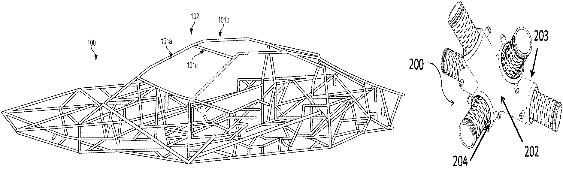
FIG. 1 shows a vehicle chassis including connecting tubes connected by one or more joint, in accordance with an embodiment of the invention.
FIG. 2a shows an example of a joint having a plurality of acceptor ports in accordance with an embodiment of the invention.
FIG. 2b shows another example of a joint having a plurality of acceptor ports in accordance with an embodiment of the invention.
FIG. 2c shows another example of a joint having a plurality of acceptor ports with different diameters in accordance with an embodiment of the invention.
FIG. 2d shows a cross-sectional view of a joint connecting a plurality of connecting tubes.
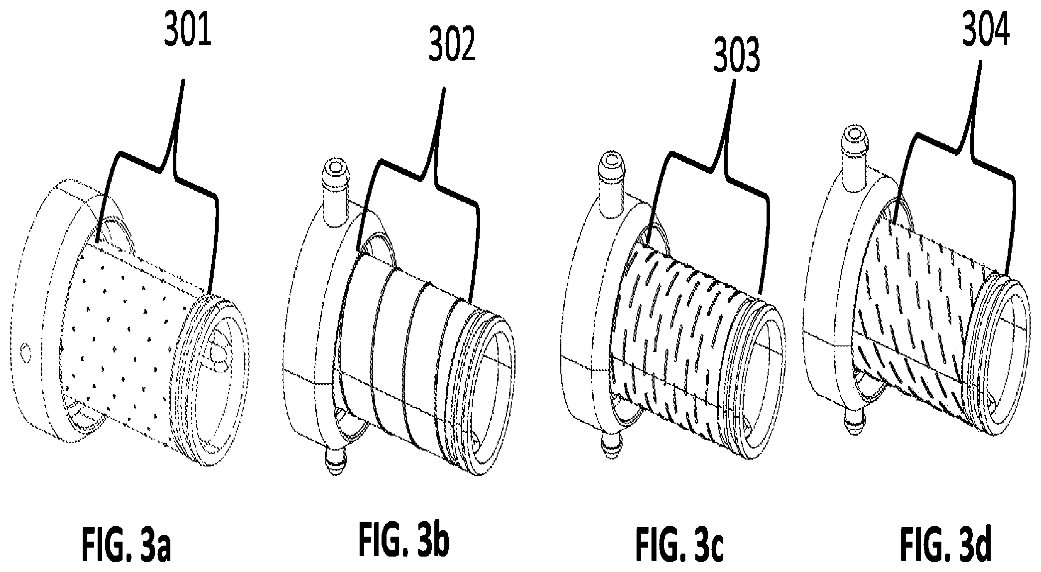
FIG. 3a shows an example of a joint protrusion with a small nubs centering feature.
FIG. 3b shows an example of a joint protrusion with a spiral path centering feature.
FIG. 3c shows an example of a joint protrusion with a labyrinth centering feature.
FIG. 3d shows an example of a joint protrusion with an interrupted helix centering feature.
FIG. 4 shows a magnified cross sectional view of an example of a connected tube and joint showing the role of centering features and the space created between a joint protrusion surface and the inner surface of a tube.
FIG. 5a shows an example of a joint with an injection orifice.
FIG. 5b shows a magnified cross sectional view of an example of an adhesive injection pathway.
FIG. 6a shows an example of a joint with a flange for integration with other construction components.
FIG. 6b shows an example of a joint with openings for routing of fluid and/or electrical components.
FIG. 6c shows a cross sectional view of an example of a joint with openings for routing of fluid and/or electrical components.
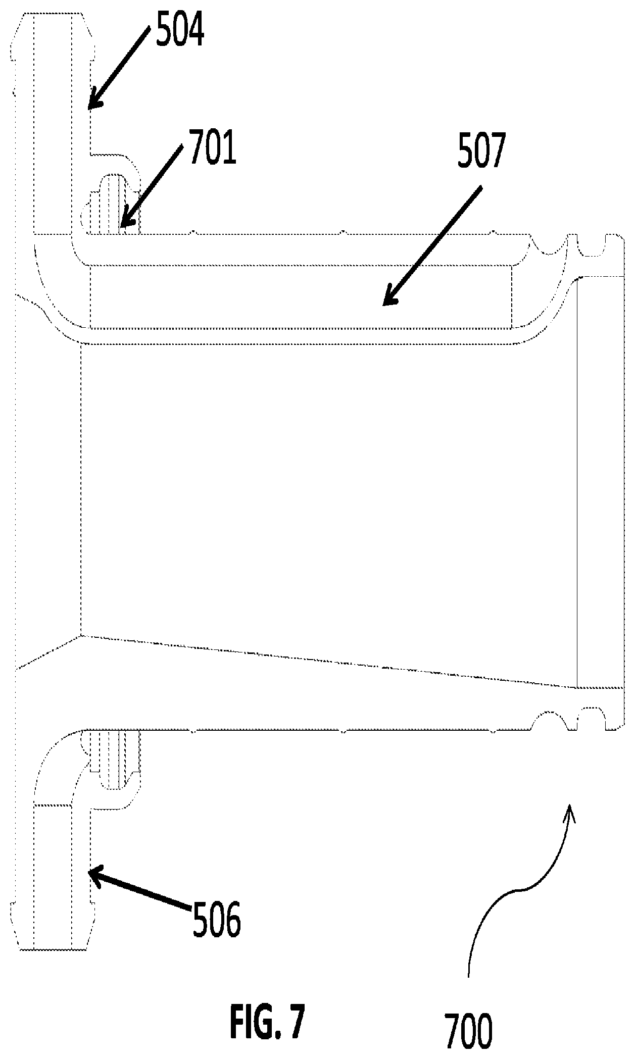
FIG. 7 shows a cross section of a joint inner protrusion that includes a seal.
DETAILED DESCRIPTION
While various embodiments of the invention have been shown and described herein, it will be obvious to those skilled in the art that such embodiments are provided by way of example only. Numerous variations, changes, and substitutions may occur to those skilled in the art without departing from the invention. It should be understood that various alternatives to the embodiments of the invention described herein may be employed.
This disclosure provides a joint member for connection of a plurality of connecting tubes, which may be used for the forming of a light weight space frame. An example of a space frame may be a vehicle chassis. Various aspects of the described disclosure may be applied to any of the applications identified here in addition to any other structures comprising a joint/tube frame construction. It shall be understood that different aspects of the invention may be appreciated individually, collectively, or in combination with each other.
FIG. 1 shows a vehicle chassis 100 including connecting tubes 101a, 101b, 101c connected by one or more nodes 102, in accordance with an embodiment of the invention. A multi-port node, or joint member, may be provided to connect carbon fiber tubes to form a two or three-dimensional structure. The structure may be a frame. In one example, a two dimensional structure may be a planar frame, while a three dimensional structure may be space frame. A space frame may enclose a volume therein. In some examples, a three dimensional space frame structure may be a vehicle chassis. The vehicle chassis may have a length, width, and height that may enclose a space therein. The length, width, and height of the vehicle chassis may be greater than a thickness of a connecting tube. Any description herein of a vehicle chassis or any type of chassis may be applied to any type of space frame, and vice versa.
A vehicle chassis may form the framework of a vehicle. A vehicle chassis may provide the structure for placement of body panels of a vehicle, where body panels may be door panels, roof panels, floor panels, or any other panels forming the vehicle enclosure. Furthermore the chassis may be the structural support for the wheels, drive train, engine block, electrical components, heating and cooling systems, seats, or storage space. A vehicle may be a passenger vehicle capable of carrying at least about 1 or more, 2 or more, 3 or more, 4 or more, 5 or more, 6 or more, 7 or more, 8 or more, ten or more, twenty or more, or thirty or more passengers. Examples of vehicles may include, but are not limited to sedans, trucks, buses, vans, minivans, station wagons, RVs, trailers, tractors, go-carts, automobiles, trains, or motorcycles, boats, spacecraft, or airplanes. A space frame may be provided for a vehicle, or for any other type of structure including, but no limited to, towers, buildings, bicycles, tricycles, bridges, lighting structures, furniture, stages, trusses, or walls. Any description herein of a chassis or vehicle chassis may apply to any type of space frame. Similarly, any description herein of nodes that may be used to connect tubes in a vehicle chassis may be applied to any type of space frame.
The vehicle chassis may provide a form factor that matches the form factor of the type of vehicle. Depending on the type of vehicle, the vehicle chassis may have varying configurations. The vehicle chassis may have varying levels of complexity. In some instances, a three-dimensional space frame may be provided that may provide an outer framework for the vehicle. The outer framework may have body panels to form a three-dimensional enclosure. Optionally, inner supports or components may be provided. Different layouts of multi-port nodes and connecting tubes may be provided to accommodate different vehicle chassis configurations. Nodes may be able to support tubes in a two or three-dimensional plane. For example, a multi-prong node may be configured to connect tubes that do not all fall within the same plane. The tubes connected to a multi-prong node may be provided in a three-dimensional fashion and may span three orthogonal axes. In alternate embodiments, some nodes may connect tubes that may share a two-dimensional plane.
The connecting tubes 101a, 101b, 101c of the vehicle may be formed from a carbon fiber material. Examples of composite materials may include high modulus carbon fiber composite, high strength carbon fiber composite, plain weave carbon fiber composite, harness satin weave carbon composite, low modulus carbon fiber composite, or low strength carbon fiber composite. In alternate embodiments, the tubes may be formed from other materials, such as plastics, polymers, metals, or metal alloys. The connecting tubes may be formed from rigid materials. The connecting tubes may have varying dimensions. For example, different connecting tubes may have different lengths. For example, the connecting tubes may have lengths on the order of about 1 inch, 3 inches, 6 inches, 9 inches, 1 ft, 2 ft, 3 ft, 4 ft, 5 ft, 6 ft, 7 ft, 8 ft, 9 ft, 10 ft, 11 ft, 12 ft, 13 ft, 14 ft, 15 ft, 20 ft, 25 ft, or 30 ft. In some instances, the tubes may have the same diameter, or varying diameters. In some instances, the tubes may have diameters on the order of about 1/16'', 1/8'', 1/4'', 1/2'', 1'', 2'', 3'', 4'', 5'', 10'', 15'', or 20''.
The connecting tubes may have any cross-sectiona shape. For example, the connecting tubes may have a substantially circular shape, square shape, oval shape, hexagonal shape, or any irregular shape. The connecting tube cross-section could be an open cross section, such as a C-channel, I-beam, or angle.
The connecting tubes 101a, 101b, 101c may be hollow tubes. A hollow portion may be provided along the entire length of the tube. In some cases, the connecting tubes may have an inner surface and an outer surface. An inner diameter for the tube may correspond to an inner surface of the connecting tube. An outer diameter of the tube may correspond to an outer surface of the tube. In some embodiments, the difference between the inner diameter and the outer diameter may be less than or equal to about 1/32'', 1/16'', 1/8'', 1/4'', 1/2'', 1'', 2'', 3'', 4, or 5''. A connecting tube may have two ends. The two ends may be opposing one another. In alternative embodiments, the connecting tubes may have three, four, five, six or more ends. The vehicle chassis frame may comprise carbon fiber tubes connected with joints 102.
The multi-port nodes 102 (e.g., joint members, joints, connectors, lugs) presented in this disclosure may be suitable for use in a vehicle chassis frame such as the frame shown in FIG. 1. The nodes in the chassis frame (100) may be designed to fit the tube angles dictated by the chassis design. The nodes may be pre-formed to desired geometries to permit rapid and low cost assembly of the chassis. The nodes can be reusable. In some cases, a first chassis can be built using a set of nodes and tubes. The first chassis can be disassembled and a second chassis can be built using at least a subset of the set of nodes and tubes. The first chassis and the second chassis can correspond to different types of vehicles. For example, the first chassis and the second chassis can be different size (e.g., volume, weight, carrying capacity) vehicles. In some cases, the first chassis and the second chassis can correspond to vehicles with different functions. Vehicle functions can include military use, commercial use, hauling, transporting one or more humans, and/or travel on a specified type of terrain.
A joint or node may be composed of a metallic material (e.g. aluminum, titanium, or stainless steel, brass, copper, chromoly steel, or iron), a composite material (e.g. carbon fiber), or a polymeric material (e.g. plastic). The joint can be formed from a thermally insulating material. The joint can be formed from a thermally conductive material. The joint may be formed of a substantially rigid material. The joint may be fabricated by 3D-printing, casting, by use of a mold, by machining, or by some combination of these processes.
FIG. 2a and FIG. 2b show examples of joints (a.k.a. nodes). FIG. 2a shows a joint, or multi-prong node, 200 with five protruding acceptor ports, or prongs, for connecting with tubes. FIG. 2b shows a joint 201 with three protruding acceptor ports for connecting tubes. A joint (i.e., multi-prong node) may have any number of protruding acceptor ports to mate with a connecting tube. For example, the joint may have at least one, two, three, four, five, six, seven, eight, nine, ten, twelve, fifteen, twenty, thirty, or fifty acceptor ports, or prongs. The joint may have less than any of the number of acceptor ports described herein. The joint may have a number of acceptor ports falling into a range between any two of the values described herein.
The joint may have a central region or hub 202. Acceptor ports 203, 204 may protrude from the central region. The central region or hub may be the portion of the joint where the acceptor ports meet. The central region or hub may have an inner protrusion. In some cases, the central region or hub may be hollow. An acceptor port may have a proximal end closer to the central region or hub. The acceptor port may have a distal end further from the central region or hub. Each acceptor port may be configured to engage with a connecting tube. An end of a connecting tube may be connected to a single acceptor port. In some examples, the connecting tube may have multiple ends. Each end may be connected to a joint. A joint may connect multiple connecting tubes to one another. In some examples, a joint may connect two, three, four, five, six, seven, eight, nine, ten or more connecting tubes to one another.
The protruding acceptor ports may have any angle relative to each other in three dimensional space, for example the angle between any two ports may be at least 1.degree., 5.degree., 10.degree., 15.degree., 20.degree., 30.degree., 45.degree., 60.degree., 75.degree., 90.degree., 105.degree., 120.degree., 135.degree., 150.degree., 165.degree., or 180.degree.. In some instances, three or more ports may be provided. The three or more ports may or may not be coplanar. The ports may be able to accept round, square, oval, or irregularly shaped tubes. Different cross-sectional shapes/dimensions for connecting tubes, ports may be configured to accommodate the different shapes/dimensions of tubes, the ports themselves may have different cross-sectional shapes/dimensions. The ports may be round, square, oval, or irregularly shaped.
A joint may have an inner protrusion designed to fit inside of a connecting tube. The inner protrusion may be a portion of an acceptor port. The inner protrusion may be tapered to provide a smooth stiffness transition when inserted in a connecting tube. For example, the diameter of the inner protrusion may increase slightly closer to the central region or hub. The diameter of the inner protrusion at a distal end of the protrusion may be less than a diameter of the protrusion at a proximal end of the protrusion. The ports have dimensions such that the inner protrusion of the ports can fit inside of a connecting tube for the purpose of engagement with the inner surface area of a connecting tube.
The joint may also have a lip designed to fit over a portion of the connecting tube. The lip may be a portion of the acceptor port. The lip can be sized and shaped such that the connecting tube can fit inside the lip for purpose of engagement of the outer surface of the connecting tube. A snug fit of the tube inside of the lip may be provided.
In the case of carbon tubes, engagement on the inside surface of a tube may be tighter because carbon tubes are fabricated by winding of composite material over a mandrel. The fabrication method of winding over a mandrel allows for higher precision of the inside tube diameter than the outer diameter. Therefore the joint protrusion for engagement with the inner surface of the tube may be designed with a narrower tolerance.
The diameter of the inner protrusion designed to fit inside of a connecting tube may be at least about 1/16'', 1/8'', 1/4'', 1/2'', 1'', 2'', 3'', 4'', 5'', 10'', 15'', or 20''. Alternatively, the diameter of the inner protrusion may be less than any of the values described herein. The diameter of inner protrusion may be tapered so that its diameter varies along its length.
A single joint may have two or more acceptor ports with non-equal diameters. For example, the joint shown in FIG. 2c shows a joint 205 designed to accept tubes of different diameters with a smaller tube being accepted at the upper port 206 and larger tubes accepted at the lower ports 207. In another example, different ports on the same joint may be able to accept tubes with a diameter ratio between different tubes of 1:2, 1:3, 1:4, 1:5, 1:6, 2:3, 2:5, 2:7, 3:5, or 3:7. Furthermore, tubes with different cross sectional shapes may be able to fit on to different ports on the same joint. For example, a joint may have a port with an inner protrusion with all or any combination of round, oval, square, rectangular, or irregularly shapes. In other implementations, a single joint may have protrusions with equal diameters and/or the same shape.
Furthermore, the joint may be configured to fit over a connecting tube as well as inside the tube. For example, an acceptor port 207 of the joint may include an inner protrusion 208 (e.g., the protrusion) and an outer protrusion 209. The inner protrusion may be capable of being inserted into the connecting tube while the outer protrusion may overlie a portion of the connecting tube. In some cases, the lip described elsewhere herein can comprise the outer protrusion. The inner protrusion of the acceptor port may contact an inner surface of a connecting tube while the outer protrusion may contact an outer surface of the connecting tube. The inner protrusion and the outer protrusion may simultaneously contact the inner and outer surfaces of the connecting tube at the same end. In this design, the connecting tube can be surrounded on both sides by the joint when the tube and joint are connected so that the joint engages both the inner and outer diameter of the connecting tube. Both an inner and outer surface of an end of the tube may contact a portion of the joint. The contact may include a full surface contact, or a partial contact.
In the joint design configured to engage both the inner and outer diameter of the tube, the joint may have an inner protrusion that extends from the central hub, or body of the joint. The inner protrusion may be inside of the outer protrusion, with an annular region or groove separating the inner protrusion and the outer protrusion. The outer protrusion may not extend from the central hub as far as the inner protrusion. The outer protrusion can be shorter than the inner protrusion. The inner protrusion may be an inner region of the joint and the second protrusion may be an outer region of the joint. The two protrusions may be co-axial or concentric such that the radial thickness of the annular region may be uniform around the circumference of the inner protrusion. The two protrusions may form substantially concentric shapes (e.g., concentric cylinders, or any other shape).
The inner protrusion may extend further (away from the body of the joint) than the outer protrusion within which the inner protrusion is located. The inner protrusion may thus have a greater length than the outer protrusion. In some instances, the ratio of lengths between the outer protrusion and the inner protrusion may be less than or equal to about 1:1, 1:2, 1:3, 1:4, 1:5, 1:6, 1:7, 1:8, 1:10, 1:12, 1:15, 1:20, 1:25, 1:30, or 1:50. The inner protrusion may be solid. Alternatively the inner protrusion may be hollow with a wall thickness of about 1/16'', 1/8'', 1/4'', 1/2'', 1'', 2'', 3'', 4'', or 5''. The outer protrusion may have a wall thickness of 1/16'', 1/8'', 1/4'', 1/2'', 1'', 2'', 3'', 4'', or 5''. The outer protrusion may be a lip that only covers a small portion of the connecting tube.
FIG. 2d shows a cross sectional view of a joint/tube assembly 211 comprising a joint 212 and connecting tubes 213. In this embodiment the protrusion designed to fit inside of a connecting tube 213 is inside of the tube and protrusion designed to fit over the outer diameter of a connecting tube 213 mates over the connecting tube. The diameter of the region designed to fit over the outer diameter of a connecting tube may be at least 1/16'', 1/8'', 1/4'', 1/2'', 1'', 2'', 3'', 4'', 5'', 10'', 15'', or 20''.
A snug fit may be provided between the inner protrusion 214 and the connecting tube 213. Similarly, a snug fit may be provided between the outer protrusion 215 and the connecting tube. A portion of the end of the connecting tube may be sandwiched between the inner protrusion and the outer protrusion. The inner and outer protrusions may pinch over the terminal end of the connecting tube.
An annular space 210 may be provided between the inner and outer protrusions 214, 215. The annular space may form a groove or channel between the inner and outer protrusions. The annular region may provide a space for insertion of a connecting tube. When the tubes and joints are assembled the tube may be pushed some distance into the annular space between the inner and outer protrusions. The tube may be pushed into the annular region only part of the way or the tube may be pushed in such that the end of the tube contacts the back of the annular region (joint body).
The joint may mate with the inside of the tube and the outside of the tube. Each end of a tube may be accepted by an acceptor port of a joint that may simultaneously contact the inner and outer surfaces of the tube at the respective end. Engagement with both the inside and outside of the tube may result in greater structural strength. The joint protrusion may enter into a connecting tube at least 1/2'', 1'', 2'', 3'', 4'', or 5''. The region of the joint that covers over the outer diameter of the tube may cover a tube length of at least 1/2'', 1'', 2'', 3'', 4'', or 5''. The ratio of the length of the tube that is engaged on the outer diameter surface compared to the engagement of the inner diameter surface may be about 1:1, 1:2, 2:3, 1:3, 1:4, 1:5, 2:1, 3:2, 3:1, 4:1, or 5:1. The joint dimensions may be determined by the adhesive volume required to bind the joint/tube assembly with sufficient structural rigidity for the intended use.
The joint may be fabricated from a single integral piece of metallic material (e.g. aluminum, titanium, or stainless steel, brass, copper, chromoly steel, or iron), a composite material (e.g. carbon fiber), or a polymeric material (e.g. plastic). For example the joint body, inner protrusion, and outer protrusion may all be formed from a single piece of material. Alternatively the joint body, inner protrusion, and outer protrusion could be machined separately and connected after fabrication. The joint protrusion and body may be permanently affixed to each other. Portions of the joint may be immovable relative to the rest of the joint. When a joint/tube assembly is formed, the structure may be rigid and joints may prevent tubes from moving relative to each other.
The inner protrusion 214 of the joint, designed to enter into a connecting tube 213, may have centering features. Centering features may be a raised pattern on the joint protrusion designed to fit inside of a connecting tube. The centering feature may be raised from an outer surface of an inner protrusion of the acceptor port. Optionally, centering features may be on the inside region of the outer protrusion. In some implementations, the centering features may be raise from both an outer surface of the inner protrusion and an inner surface of the outer protrusion of the acceptor port. The height of a raised centering feature may be at least 0.001'', 0.005'', 0.006'', 0.007'', 0.008'', 0.009'', 0.010'', 0.020'', 0.030'', 0.040'', or 0.050''.
FIGS. 3a-d show detailed views of four possible joint centering feature embodiments. FIG. 3a shows a small nub centering feature 301, this feature comprises a pattern of raised dots on a tube engagement region of the joint protrusion. A tube engagement region of the joint protrusion may be a portion of the joint protrusion configured to come into contact with a surface of the tube. The tube engagement region may be configured to be inserted into the tube. The dots may be provided in one or more row or column, or in staggered rows and/or columns. The raised dots may have a diameter of at least 0.001'', 0.005'', 0.006'', 0.007'', 0.008'', 0.009'', 0.010'', 0.020'', 0.030'', 0.040'', or 0.050''.
FIG. 3b shows a spiral path centering feature 302, this feature comprises a continuous raised line that winds around the full length of the tube engagement region of the joint protrusion. The continuous raised line may wrap around the tube joint protrusion a single time or multiple times. Alternative designs may comprise centering features with a raised spiral centering feature that does not wrap around the full diameter of the tube engagement region. In alternative embodiments the spiral centering feature may wind around 10.degree., 20.degree., 30.degree., 40.degree., 50.degree., 60.degree., 70.degree., 80.degree., 90.degree., 100.degree., 110.degree., 120.degree., 130.degree., 140.degree., 150.degree., 180.degree., 190.degree., 200.degree., 210.degree., 220.degree., 230.degree., 240.degree., 250.degree., 260.degree., 270.degree., 280.degree., 290.degree., 300.degree., 310.degree., 320.degree., 330.degree., 340.degree., 350.degree., or the full 360.degree. of the circumference of the engagement region. The centering feature may further comprise multiple raised lines that wind around the full length of the tube without intersecting in a fashion similar to multi-start screw threads.
FIG. 3c shows a labyrinth centering feature 303, this feature comprises raised dashed lines circumscribing the tube engagement region of the joint at a 90 degree angle to the direction of the length of the joint protrusion. Adjacent dashed lines in the labyrinth centering feature are organized in a staggered pattern. Multiple rows of dashed lines may be provided. The dashed lines may be substantially parallel to one another. Alternatively, varying angles may be provided.
FIG. 3d shows an interrupted helix centering feature 304, this feature comprises raised dashed lines circumscribing the tube engagement region of the joint at a 45 degree angle to the direction of the length of the tube engagement region. In another example, the centering feature could have a raised line circumscribing the tube engagement region at an angle of 1.degree., 5.degree., 10.degree., 15.degree., 20.degree., 30.degree., 45.degree., 60.degree., 75.degree., 90.degree., 105.degree., 120.degree., 135.degree., 150.degree., 165.degree., or 180.degree.. The dashed lines in the centering features shown in FIG. 3c and FIG. 3d may have a length of at least 0.005'', 0.006'', 0.007'', 0.008'', 0.009'', 0.010'', 0.020'', 0.030'', 0.040'', 0.050'' or 0.100''.
Other patterns in addition to those described in FIG. 3a-FIG. 3d may be used. Alternative patterns may include dashed lines at irregular angles or spacing, a combination of lines and dots, or a group of solid lines winding around the engagement region with uniform or non-uniform spacing between the lines. In some instances, the centering features may be patterned so a direct straight line may not be drawn from a distal end of an inner protrusion to the proximal end without intersecting one or more centering feature. This may force adhesive to take a more roundabout path and encourage spreading of the adhesive, as described further elsewhere herein. Alternatively, a straight line may be provided from a distal end to a proximal end of the inner protrusion without intersecting one or more centering feature.
The centering features may be added to the joint protrusion with different densities. For example, a joint protrusion may be fabricated such that 90% of the protrusion is covered with raised centering features. In the case with 90% centering feature coverage the features may be very closely spaced. Alternatively the centering features may cover at least 5%, 10%, 15%, 20%, 25%, 30%, 40%, 45%, 50%, 55%, 60%, 65%, 70%, 75%, 80%, 85%, 90%, or 95% of the protrusion. The centering features may cover less than any of the percentages described herein. The centering features may fall within a range between any two of the percentage values described herein.
The centering features may be raised such that a joint/tube assembly comprises space between an inner surface of the connecting tube and the surface of the joint protrusion designed to enter into a connecting tube. The tolerance between the inner tube diameter and the protrusion may be such that the joint and tube form a force fit connection. In the case of a force fit connection, centering features may or may not deform upon tube insertion in to the joint. The centering features may center the joint protrusion inside of a connecting tube such that the distance between the inner surface of the connecting tube and the surface of the joint protrusion may have a uniform radial thickness. Alternatively the centering features may encourage non-uniform distribution of the space between the joint protrusion and the connecting tube.
In some cases, a seal can be provided on the joint protrusion. FIG. 7 shows a cross section of a joint inner protrusion that includes a seal 701. The seal can be a rubber seal. The seal can be a metal seal. The seal can be a plastic seal. The seal can be formed from a polymer material. The seal can be formed from Teflon. The seal can be provided on an end of an inner protrusion closest to the joint body. In some cases, a seal can additionally or alternatively be provided on an end of the inner protrusion that is farthest from the joint body. When a tube is fitted on the inner protrusion the seal can form an air tight, dust tight, and/or liquid tight seal between the inner protrusion and the tube. In some cases, an additional seal can be provided on the inner diameter of the tube that is connected to the inner protrusion. The tube and the joint protrusion can be sealed completely by the seal on the protrusion and/or on the tube such that an additional sealing mechanism can be omitted.
FIG. 4 shows a detailed cross sectional view of a connecting tube 401 engaged with a joint 402 with centering features 403. The joint may have an inner protrusion that may be a small diameter engagement region of the joint. The centering features center the inner protrusion inside of a connecting tube such that the center of the connecting tube and the center of the join protrusion are co-axial. The centering features create a space 404 between an outer surface of the small diameter engagement region of the joint and the inner surface of the connecting tube. Said space may be filled with adhesive to bind the tube and joint assembly. The adhesive may be confined to the space between the outer surface of the inner protrusion of the joint and the inner surface of the connecting tube. This may be the case when the centering features are provided on the outer surface of the inner protrusion.
In some alternative embodiments, a space may be provided between an outer surface of the connecting tube and an inner surface of an outer protrusion 405 of the joint. Optionally, one or more centering features may be provided on an inner surface of the outer protrusion of the joint, which may create the space. Adhesive may fill the space between the inner surface of the outer protrusion and the outer surface of the tube. Either or both of the joint and the adhesive can be heated prior to injecting the adhesive into the space to achieve a desired flowability or viscosity of the adhesive. The centering features may have any configuration, such as those described elsewhere herein. The centering features may provide a uniform, or non-uniform space around the circumference of the tube. In some instances, stopping features may be provided, that may prevent adhesive from leaking outside the portion of the outer surface of the tube that is covered by the outer protrusion.
Adhesive may contact only the tube inner surface, only the tube outer surface, or both. In some implementations, centering features may be provided on both an outer surface of an inner protrusion of a joint and an inner surface of an outer protrusion of the joint. A space may be formed between an inner surface of the tube and an outer surface of the inner protrusion, as well as an outer surface of the tube and an inner surface of the outer protrusion. Adhesive may be used to fill both the space between an inner surface of the tube and an outer surface of the inner protrusion, and the space between an outer surface of the tube and an inner surface of the outer protrusion.
An adhesive may be used to bind the joint and tube together to form a rigid structure. The adhesive may firmly affix the joint and tube to one another in forming a vehicle chassis. The adhesive may be any flowable adhesive, such as an epoxy, glue, resin, or cement. The joint may comprise specific passages and openings to enable post-assembly injection of adhesive to specific locations.
FIG. 5a and FIG. 5b show features of the joints designed for adhesive injection into the space between the surface of the inner protrusion of the joint and the inner surface of the connecting tube. FIG. 5a shows a joint 501, the joint has an orifice for adhesive injection or vacuum attachment 502.
FIG. 5b shows a magnified cross sectional view of a joint 503 with a vacuum port 504 mated to a connecting tube 505. An injection port 506 may be provided opposite the vacuum port. The injection port may be provided on the joint. A vacuum port may be connected to a negative pressure source, such as a vacuum pump. An injection port may be connected to an adhesive reservoir. In some instances, a positive pressure may be exerted on or by the adhesive reservoir. The cross-sectional view in FIG. 5b shows the fluid pathway (e.g., channel) 507 inside of a wall of the inner joint protrusion 507. The fluid pathway may pull injected adhesive from an adhesive source (connected reservoir) at the injection port 506 into the space between the surface of the joint protrusion and the surface of the inner diameter of the connecting tube. Vacuum ports 504 and injection ports 506 may be positioned on opposite sides of the joint to distribute adhesive uniformly. For example, they may be provided circumferentially opposing one another on an acceptor port of a joint. They may be provided at or near a proximal end of an acceptor port for a joint. Alternatively, they may be provided at or near a distal end of an acceptor port of the joint, or any combinations thereof. A joint may have at least about 1, 2, 3, 4, 5, 10, 15, or 20 vacuum ports or injection ports on each protrusion. Vacuum and injection ports can be positioned far from, in close proximity to, or co-axially with an internal joint feature such as the fluid pathway inside of a wall of the inner joint protrusion, which may provide uniform adhesive coating. Optionally, the vacuum and injections ports may be alternatingly positioned in close proximity or co-axially with the internal node features. Vacuum and injection ports can be optimally positioned on a node to enable usage of a combined vacuum/injection tool with set vacuum/injection port spacing and geometry. The number of vacuum ports and injection ports may not necessarily have to be equal. Implementations with one vacuum port and a plethora of injection ports, or one injection port and a plethora of vacuum ports may be possible.
The distribution of the adhesive in the space may be influenced by the centering features. For example, a nub centering feature may permit maximum bond area between the joint and tube. In another case, a spiral path centering feature may generate a long path for the adhesive to flow. A spiral path centering feature may be preferable in embodiments where the adhesive needs to fill a space far from the injection site. In another case, a labyrinth centering feature may force uniform distribution of the adhesive around the tube. A labyrinth centering feature may be preferable in embodiments where uniform distribution of the adhesive is desired for structural stability. Labyrinth and interrupted helix centering features may force the adhesive to uniformly distribute upon injection by creating an internal fluid path for the adhesive which may traverse the space uniformly. In some instances, the centering features may be configured to force the adhesive to travel circumferentially around the tube. The centering features may also be configured to force the adhesive to travel along the length of the tube. Preferably, centering features may be configured to cause the adhesive to spread evenly along the surface of the tube, which may include both the circumferential and lengthwise spreading of the adhesive.
Adhesive may be injected into the space by vacuum or pressure injection. In the case of vacuum injection at least one port may be connected to a low pressure source and at least one other port may be connected to an adhesive reservoir, upon engagement of the low pressure source adhesive may be sucked into the space from the reservoir. Alternatively a port may be connected to a pressure source and adhesive may be pushed into the space.
Joints may be fabricated with nipples attached to the injection port or vacuum port 504. The nipples may connect to the pressure source, vacuum source, and/or adhesive reservoir. The nipples may be protrusions that may stick out of the joint (see, e.g., 606 of FIG. 6). Alternatively, the nipples need not protrude from the joint. The nipples may include an opening that may be fluidically connected to an internal space between a tube and one or more protrusions of the joint. The nipples may be in fluid communication with a fluid pathway 507. A nipple may be formed with an internal channel that is in fluid communication with an annular region of the acceptor port and/or a surface of the acceptor port. The internal channel may be in fluid communication with an exterior surface of an inner protrusion of the acceptor port. The internal channel may or may not be in fluid communication with an interior surface of an outer protrusion of an acceptor port. The use of nipples may simplify the injection process by removing the need for specific hardware or tools; for example fittings, nozzles, or syringes. The nipples may be removed after assembly of a structure. For example, after the adhesive has been inserted and/or hardened, the nipples may be removed. Nipples may have the form of 216 in FIG. 2c. The nipples may extend from the protrusion 1/16'', 1/8'', 1/4'', 1/2'', 1'', 2'', 3'', 4'', 5'', or 10''. Similarly they may have a diameter of 1/16'', 1/8'', 1/4'', 1/2'', 1'', 2'', 3'', 4'', 5'', or 10''.
Joints may comprise integrated structural features. Integrated structural features may include fluid plumbing, electrical wiring, electrical buses, panel mounts, suspension mounts, or locating features. Integrated structural features may simplify the chassis design and decrease the time, labor, parts, and cost needed to construct the chassis structure.
Joints may comprise mounting features for shear panels or body panels of a vehicle. Mounting features on the joints may allow panels to be connected directly to a vehicle chassis frame. Mounting features on the joints may be designed to mate with complimentary mating features on the panels. For example mounting features on the joints may be flanges with holes for hardware (e.g. screws, bolts, nuts, or rivets), snaps, or flanges designed for welding or adhesive application. FIGS. 6a-c show features of the joints designed for integration with other systems on-board a structure, such as a vehicle. Joints may be designed to integrate with shear panels or body panels of a structure.
FIG. 6a shows a joint 601 with a flange 602. The flange 602 may be used to connect to a shear panel or body panel (not shown). In the case of use of the joint members to construct a vehicle chassis, joint member may be integrated with a suspension system. A suspension system may comprise hydraulic, air, rubber, or spring loaded shock absorbers. The suspension system may connect to the joint member by an attachment to a flange 602.
Joints may include electrical connections. Electrical connections integrated into the joints may be electrically insulated. Electrical connections integrated into the joints may be in communication with wiring routed through the tubes connected to the joint. The electrical wiring may be used to provide power to systems on board a vehicle and/or to provide power to a battery to start or run the vehicle engine. Systems on board a vehicle that use power from the integrated joints may include, navigation, audio, video display, power windows, or power seat adjustment. Power distribution within a vehicle may travel exclusively through a tube/joint network. FIG. 6b shows a possible joint embodiment for routing of electrical wires throughout a structure 603. The joint shown in FIG. 6b has with an inlet region 604; this inlet could be used for insertion of electrical connections or wires. Electrical wires may be inserted into the inlet region and routed from the joint to the tube for transmission throughout the chassis. One or more system that may be powered using the electrical wires may connect with the wire through the inlet region.
Joints may comprise an integrated heating and cooling fluid system to provide heat and air conditioning in the vehicle chassis. Other applications may include cooling and/or heating various components of the vehicle. Integration of fluid (e.g. gas or liquid) systems into the joint/tube construction may partially or fully eliminate the need for conventional air ducts and plumbing from vehicle design. Joints may route hot or cold fluid from a production source (e.g. electric heating element, engine block heat exchanger, refrigerator, air conditioning unit, or boiler) to a location in the chassis where a passenger or vehicle operator may wish to heat or cool the interior. Joints may contain integrated components to intake hot or cold fluid from a source, distribute hot or cold fluid, and vent hot or cold fluid at a location away from the source. Joints and tubes in the assembly may be thermally insulated using fiberglass, foam insulation, cellulose, or glass wool. The joint and tube assembly may be fluid tight. In the case of a joint comprising an integrated fluid system the joint embodiment shown in FIG. 6b may be used. An inlet such as the one illustrated in the FIG. 604 may be used to route fluid for heating or cooling throughout a structure by means piping the fluid between a plurality of joints through the connector tubes. A cross sectional view of a joint 605 used for routing of fluid or electricity is shown in FIG. 6c. The passageways used for routing of fluid and electricity may be the same passageways or they may be separate. Internal node routing may keep two or more fluids separate within a node while still providing desired routing between tubes, or from tube to node-mounted connectors or features.
Joints may include integrated locating or identifying features. The features may enable automated identification or handling of the joints during assembly and processing. Examples of locating features may include a cylindrical boss (e.g. a boss with a flat and radial groove), an extruded C-shape with a cap, a bayonet or reverse bayonet fitting with a non-symmetric pin pattern, a hook feature, or other features with geometry that may uniquely define the feature orientation and position when examined. The orientation and/or position of the joint may be determined to a 6 axis pose when the locating features are examined. For example, the position of the joint in three dimensions of space and/or orientation of the joint about three or more axes may be determined.
These locating features may be interfaced to or grasped by robotic grippers or work holding tools. The interface of the joint may be fully defined once the grasping motion begins, is partially finished, or is complete. The locating features may enable repeatable and optionally automated positioning of the joints prior to and during space frame assembly. The defining geometry of the features may also enable automated systems to coordinate the motion of multiple joints along defined paths in space during insertion of tubes into the joints. At least two tubes may be inserted into multiple joints in parallel without resulting in geometric binding during assembly.
The integrated locating feature may further comprise integral identifying features. For example identifying features may be a one dimensional bar code, a two dimensional QR code, a three dimensional geometric pattern, or a combination of these elements. The identifying feature may encode information about the joint to which it is attached. This joint information may include: geometry of the joint, including the orientation of the tube entries relative to the identifying/location feature; material of the joint; positioning of adhesive injection and vacuum ports relative to the identifying/locating features; adhesive required by the joint; and joint tube diameters. The combined identifying/locating feature may enable automated positioning of joints for assembly without requiring external information to be supplied to the automated assembly cell.
While preferred embodiments of the present invention have been shown and described herein, it will be obvious to those skilled in the art that such embodiments are provided by way of example only. It is not intended that the invention be limited by the specific examples provided within the specification. While the invention has been described with reference to the aforementioned specification, the descriptions and illustrations of the embodiments herein are not meant to be construed in a limiting sense. Numerous variations, changes, and substitutions will now occur to those skilled in the art without departing from the invention. Furthermore, it shall be understood that all aspects of the invention are not limited to the specific depictions, configurations or relative proportions set forth herein which depend upon a variety of conditions and variables. It should be understood that various alternatives to the embodiments of the invention described herein may be employed in practicing the invention. It is therefore contemplated that the invention shall also cover any such alternatives, modifications, variations or equivalents. It is intended that the following claims define the scope of the invention and that methods and structures within the scope of these claims and their equivalents be covered thereby.
* * * * *
References
-
sculpteo.com/blog/2016/01/20/3d-printing-transforms-the-automotive-industry
-
3dprintingindustry.com/news/design-democracy-drones-meet-3d-printed-cars-self-driven-future-98125
-
localmotors.com/3d-printed-car
-
stratasys.com/industries/automotive
-
andreaspringerstudio.com/architecture/grasshopper
-
compositesworld.com/articles/carbon-fiber-race-car-technolobv-hits-the-streets
-
3dprintsoftheworld.com/object/vrz-1-tack-bike-frame-3d-printed-lugs
-
m/vw.instructables.com/id/Custom-3D-Printed-Carbon-Fiber-Bike-Framer
-
wym.dezeen.com/2013/03/07/road-ready-3d-printed-car-on-the-way
-
nbcnews.com/tech/innovation/fine-ride-worlds-first-3-d-printed-bike-frame-weighs-in30761
-
wwitt.flyingmachine.com.au/3d-printed-titanium-bike-of-the-future
-
wywv.wired.com/2013/02/3d-printed-car
-
wired.com/2014/03/edag-3-d-printed-car
D00000
D00001
D00002
D00003
D00004
D00005
D00006
D00007
XML
uspto.report is an independent third-party trademark research tool that is not affiliated, endorsed, or sponsored by the United States Patent and Trademark Office (USPTO) or any other governmental organization. The information provided by uspto.report is based on publicly available data at the time of writing and is intended for informational purposes only.
While we strive to provide accurate and up-to-date information, we do not guarantee the accuracy, completeness, reliability, or suitability of the information displayed on this site. The use of this site is at your own risk. Any reliance you place on such information is therefore strictly at your own risk.
All official trademark data, including owner information, should be verified by visiting the official USPTO website at www.uspto.gov. This site is not intended to replace professional legal advice and should not be used as a substitute for consulting with a legal professional who is knowledgeable about trademark law.